

Page 1
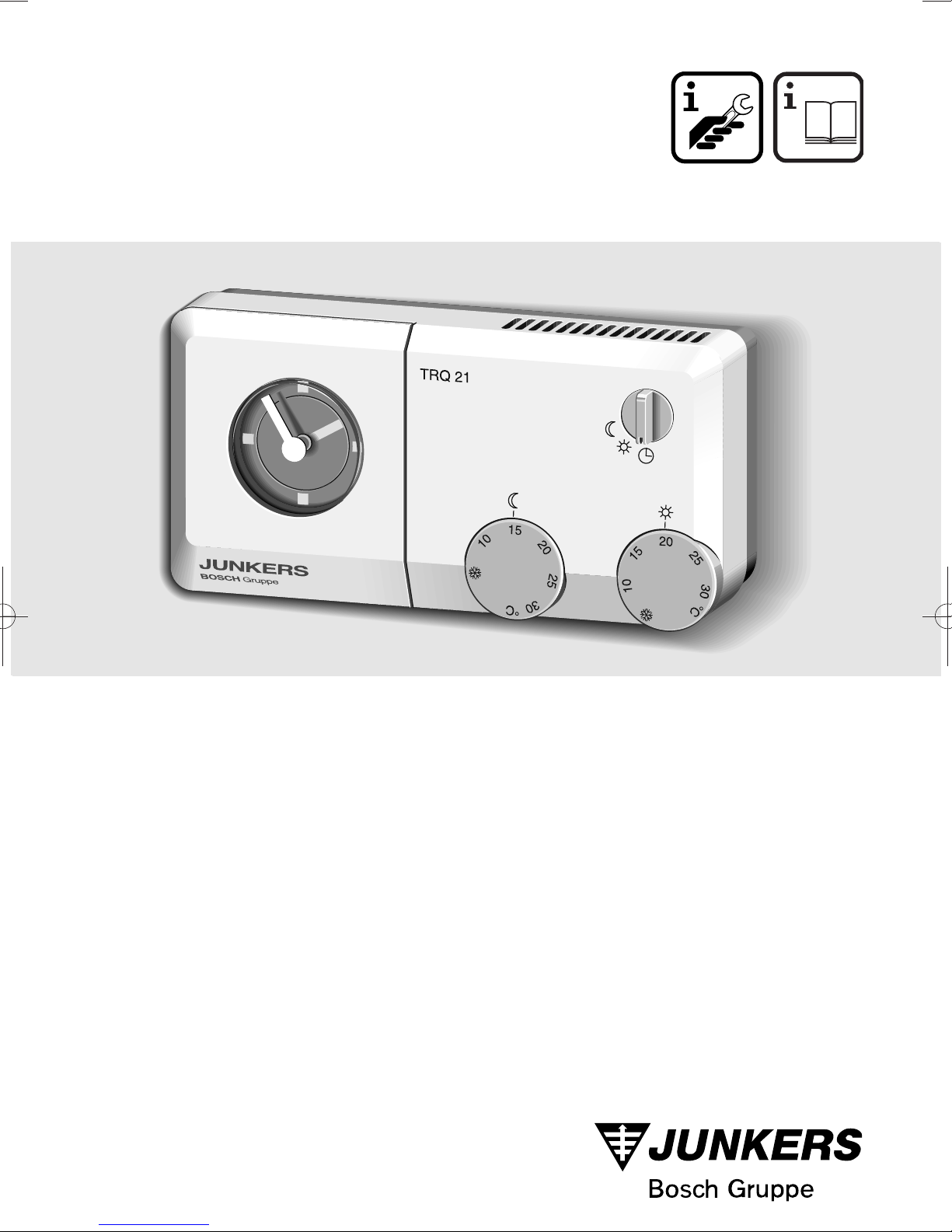
TRQ 21 W
7744901055
JU 1008/1
6720602434(02.95)
OSW
Page 2
TRQ 21 W
Deutsch
1 Anwendung..................................4
2 Technische Daten........................4
3 Sicherheitshinweise.....................4
4 Montage.......................................4
5 Bedienung ..................................5
6 Tips zum Energiesparen.................6
7 Fehlersuche.................................6
English
1 Application...................................7
2 Technical data .............................7
3 Safety Instructions.......................7
4 Installation ...................................7
5 Operation.....................................8
6 Tips for Saving Energy....................9
7 Error Localisation.........................9
Italiano
1 Applicazione ..............................16
2 Dati tecnici.................................16
3 Indicazioni di sicurezza..............16
4 Montaggio..................................16
5 Comando...................................17
6 Consigli per risparmiare energia ..18
7 Ricerca di anomali.....................18
Nederlands
1 Gebruik......................................19
2 Technische gegevens................19
3 Veiligheidsvoorschriften.............19
4 Montage.....................................19
5 Bediening...................................20
6 Tips voor energiebesparing..........21
7 Opsporen van storingen ............21
Français
1 Utilisation...................................10
2 Caractéristiques techniques ......10
3 Conseils de sécurité ..................10
4 Montage.....................................10
5 Utilisation...................................11
6 Conseils d’économie d’énergie ....12
7 Pannes - Causes - Rèmedes ....12
Español
1 Utilización ..................................13
2 Datos técnicos...........................13
3 Indicaciones de seguridad.........13
4 Montaje......................................13
5 Manejo.......................................14
6 Consejos para el ahorro
de energía .....................................15
7 Búsqueda de averías.................15
Dansk
1 Anvendelse................................22
2 Tekniske data ............................22
3 Sikkerhedsforskrifter..................22
4 Montering...................................22
5 Betjening....................................23
6 Energispareråd..............................24
7 Fejlsøgning................................24
Porto
1 Utilização...................................25
2 Dados técnicas..........................25
3 Indicações de segurança...........25
4 Montagem..................................25
5 Comando...................................26
6 Instruções sobre economia
de energia......................................27
7 Localização de defeitos.............27
2
Page 3
min.
0,3m
0,3m
0,6m
1,2 - 1,5m
6 mm 6 mm3,5 mm
1234
BOSCH Gruppe
QUARTZ
6
7
8
9
10
11
12
13
14
15
16
17
18
19
20
21
22
23
24
1
2
3
4
5
0
1
1
Ø 55 mm
3,5 mm
1
1
0
0
1
2 3
54
TRQ 21 W
b
e
n
f
a
g
h
m
j
i
l
k
d
b
d
c
b
3
Page 4

D
TRQ 21 W
1 Anwendung
Der TRQ 21 W ist ein Raumtemperaturregler
mit Stetigausgang zum Ansteuern der in
11
bis aufgeführten Junkers-Gasheizgeräte.
Dieser Raumtemperaturregler mit Zeit-
schaltuhr hat sich bei Etagenheizungen bis
Deutsch
Deutsch
ca. 80 m
2
Wohnfläche bewährt und ent-
spricht den gesetzlichen Vorschriften.
Für Anlagen mit Fußbodenheizungen oder
Klimaböden ist der TRQ 21 W nicht geeignet.
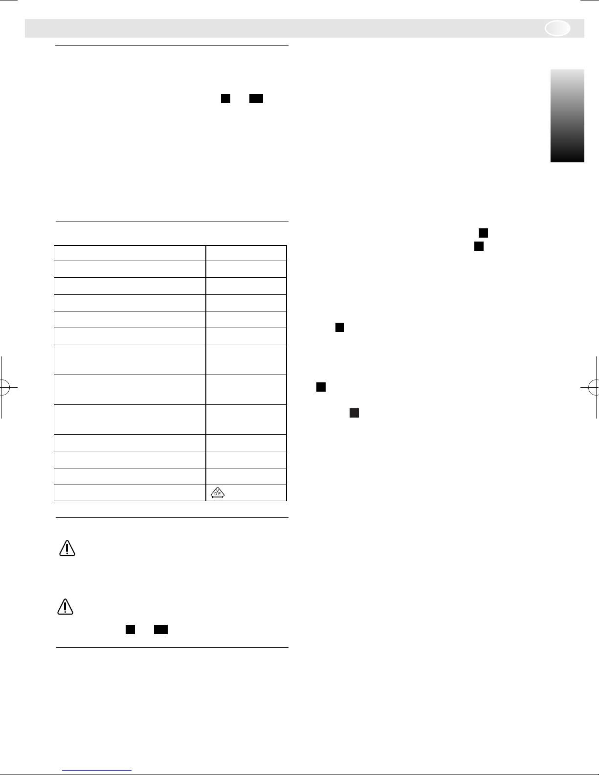
2 Technische Daten
Höhe 82 mm
Breite 165 mm
Tiefe 42 mm
Nennspannung DC 24 V
Nennstrom 0,01 A
Regelbereich 6 °C … 30 °C
minimale Temperatur- 0,05 K/min
änderungs-Geschwindigkeit
Reglerausgang stetig,
2,5 V … 24 V
zulässige
Umgebungstemperatur 0 °C … 35 °C
Gangreserve 50 h
Schutzklasse III
Schutzart IP 20
VDE-Zeichen erteilt
3 Sicherheitshinweise
Der Raumtemperaturregler TRQ 21 W
wird direkt an das Gasheizgerät angeschlossen. Schließen Sie den Regler
nicht an das 230-V-Netz an.
Verwenden Sie den TRQ 21 W nur in
Verbindung mit den in bis aufge-
116
führten Junkers-Gasheizgeräten.
4 Montage
zungsanlage geeignet sein. An den dort installierten Heizkörpern dürfen keine Thermostatventile montiert sein.
6
Besser ist es Handventile mit Voreinstellung
einzubauen, damit die Leistung der Heizkörper im Montageraum des TRQ 21 W so
knapp wie möglich einstellbar ist.
Wählen Sie als Montageort möglichst eine
Innenwand und achten Sie darauf, daß weder Zugluft noch Wärmestrahlung auf den
Regler einwirken können. Unterhalb des
Reglers muß ausreichend Platz vorhanden
sein, damit die Raumluft ungehindert durch
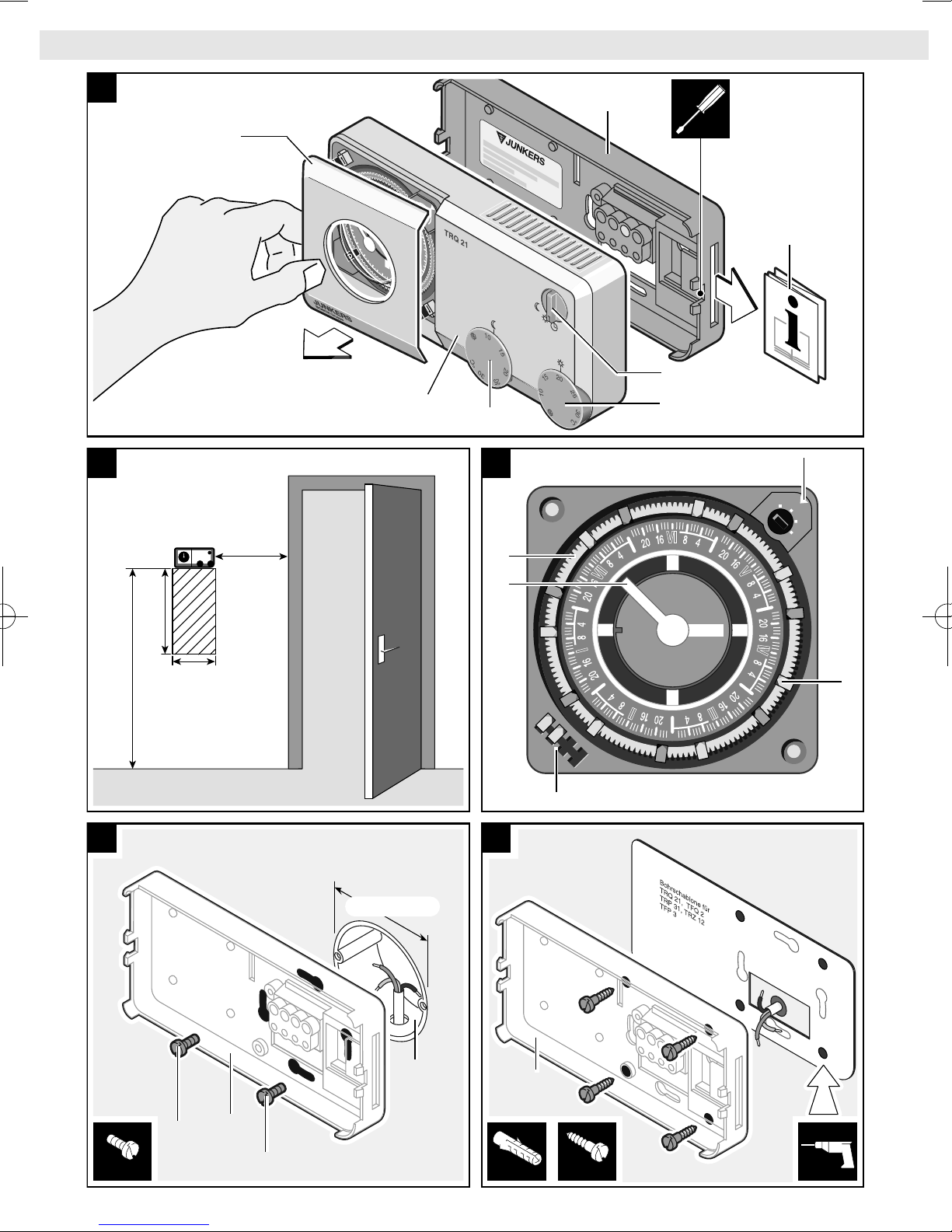
die Lüftungsöffnung zirkulieren kann (Schraffierter Bereich in ). Beachten Sie die empfohlenen Abstandsmaße in .
2
2
4.2 Befestigung des Reglers
Ziehen Sie zur Montage das Oberteil des
Reglers (a) vom Sockel (b) ab. Hebeln Sie
dazu das Gehäuse mit einem Schraubendreher auf ( ).
1
Der Sockel (b) des TRQ 21 W kann entweder mit zwei Schrauben (d) auf eine
handelsübliche Unterputzdose (c) mit
Ø55mm montiert ( ) oder aber mit Dübeln
4
(6 mm) und Schrauben (Ø 3,5 mm, Linsenkopf) direkt in der Wand verankert werden
5
( ). Verwenden Sie hierfür die beigepackte
Bohrschablone.
4.3 Elektrischer Anschluß
Der Raumtemperaturregler TRQ 21 W wird
mit einer Gleichspannung von 24 V betrieben, die vom Gasheizgerät über eine dreiadrige Verbindungsleitung bereitgestellt
wird. Über diese Leitung wird auch das Steuersignal zum Heizgerät geführt.
Zur Vermeidung von Störungen muß diese
Leitung von 230 V bzw. 400 V führenden
Leitungen getrennt verlegt werden. Sind induktive äußere Einflüsse z. B. durch Starkstromkabel, o. ä. zu erwarten, so muß die
Leitung geschirmt ausgeführt werden.
4.1 Allgemeines
Wichtig für die Regelqualität des Raumtemperaturreglers ist die Wahl eines geeigneten
Montageortes. Der Montageraum muß für
die Temperaturregelung der gesamten Hei-
4
Page 5
TRQ 21 W
D
Verwenden Sie Elektrokabel der Bauart
NYM mit folgenden Leitungsquerschnitten:
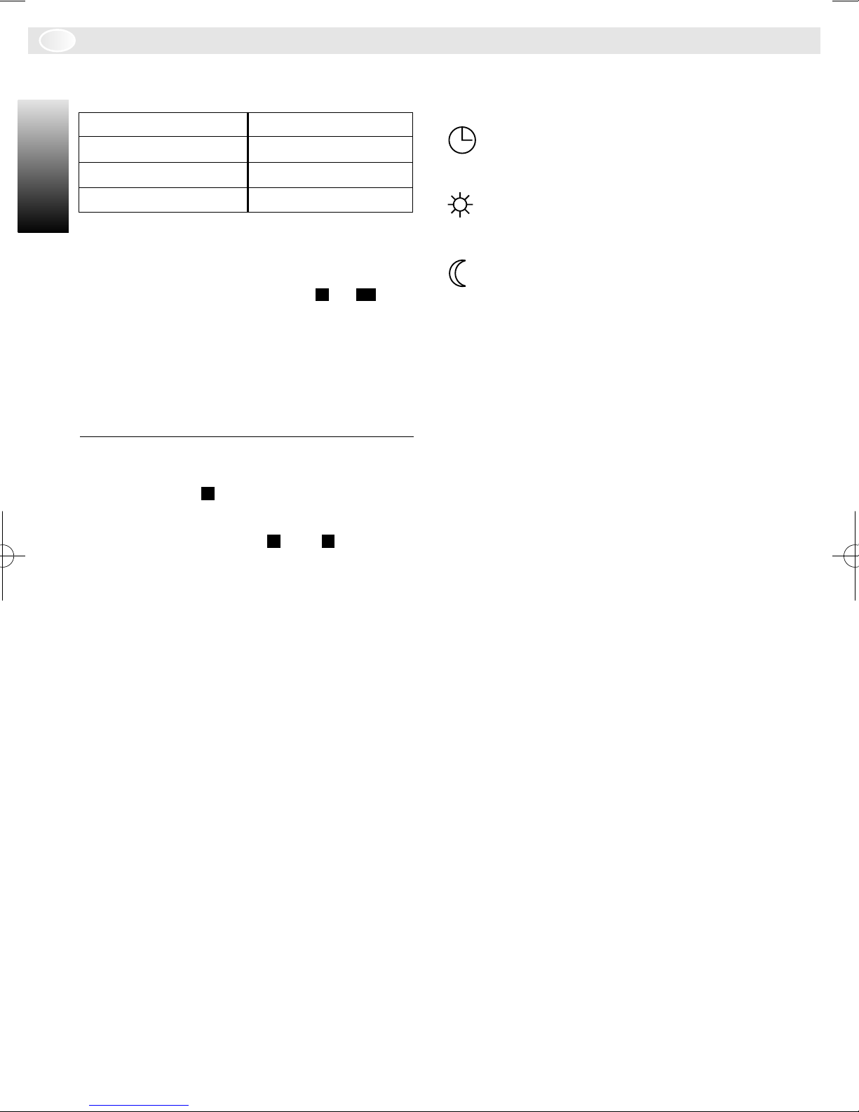
Leitungslänge: Querschnitt:
bis 20 m
bis 30 m
ab 30 m
2
2
2
0,75 bis 1,5 mm
1,00 bis 1,5 mm
1,50 mm
2
2
2
Vergewissern Sie sich, daß die Leitung
spannungsfrei ist, und verbinden Sie den
Regler mit einem dreiadrigen Kabel entsprechend Anschlußplan ( bis ) mit dem
116
Gasheizgerät.
4.4 Inbetriebnahme
Stecken Sie das Regleroberteil (a) nach Anschluß der elektrischen Leitungen auf den
Sockel (b), und nehmen Sie das Gasheizgerät in Betrieb.
5 Bedienung
Zum Einstellen der Schaltzeiten nehmen Sie
die Abdeckhaube (e) der Schaltuhr ab ( ).
Der Raumtemperaturregler TRQ 21 W besitzt folgende Bedienelemente ( und ):
e Abdeckhaube
f Betriebsartenschalter
g Temperatureinstellknopf Normalbetrieb
h Temperatureinstellknopf Absenkbetrieb
i Plexiglasscheibe mit aufgedrucktem
Zeiger
j 7-Tage-Ring
k Depot mit Reservesteckreitern
l Steckreiter rot oder blau
m Zeitmarkierung für 7-Tage-Ring
n Kurzbedienungsanleitung:
Im Fach auf der rechten Seite des
Sockels befindet sich die Kurzbedienungsanleitung JU 1007. Hier finden
Sie in Stichworten alles Wesentliche
zur Bedienung.
5.1 Betriebsartenschalter (f)
Folgende Betriebsarten sind möglich:
1
31
Automatischer Wechsel zwischen Normalbetrieb und Absenkbetrieb zu den
an der Schaltuhr eingestellten Zeiten.
Normalbetrieb: Dauernde Regelung
der Raumtemperatur auf den am Drehknopf (g) eingestellten Wert.
Absenkbetrieb: Dauernde Regelung
der Raumtemperatur auf den am Drehknopf (h) eingestellten Wert.
5.2 Drehknöpfe (g) und (h)
Mit diesen Drehknöpfen stellen Sie die gewünschte Raumtemperatur für den Normalbetrieb (g) bzw. den Absenkbetrieb (h) ein.
Der Temperaturbereich geht jeweils von
6 bis 30 °C.
5.3 Schaltuhr
Die Schaltuhr ermöglicht bei entsprechend
gewählter Betriebsart das automatische Umschalten zwischen Normalbetrieb und Absenkbetrieb. Der kürzeste Schaltabstand
(engster Abstand zwischen zwei Steckreitern
auf dem 7-Tage-Ring) beträgt 2 Std. Die
Steckgenauigkeit (Abstand zwischen zwei
benachbarten Steckpositionen auf dem 7Tage-Ring) beträgt 30 min.
5.3.1 Einstellen der Uhrzeit
Drehen Sie die Plexiglasscheibe mit aufgedrucktem Zeiger (i), um die aktuelle Uhrzeit
einzustellen. Die Scheibe darf nur im Uhrzeigersinn gedreht werden. Der 7-Tage-Ring (j)
darf nicht gedreht werden. Beachten Sie,
daß die Uhr im 7-Tage-Betrieb läuft. Die eingestellte Uhrzeit (24 h und Wochentag) können Sie auf dem 7-Tage-Ring (j) an der Zeitmarkierung (m) ablesen.
5.3.2 Einstellen der Schaltzeiten
• Rote Steckreiter = Normalbetrieb.
• Blaue Steckreiter = Absenkbetrieb.
Zum korrekten Betrieb der Schaltuhr müssen
die Steckreiter im Wechsel rot/blau gesteckt
sein.
Stecken Sie die roten und blauen Steckreiter
(l) für jeden Tag auf die gewünschte Position
am 7-Tage-Ring (j).
Nicht benötigte Steckreiter lassen Sie in den
Depots (k) stecken.
Deutsch
Deutsch
5
Page 6
D
TRQ 21 W
5.3.3 Gangreserve
Die Schaltuhr verfügt nach mindestens 3-tägigem Betrieb an der Stromversorgung über
eine Gangreserve von ca. 50 Stunden.
Während dieser Zeit läuft die Uhr über einen
Akku weiter.
Achten Sie darauf, daß die Stromversorgung
Deutsch
Deutsch
nicht länger als 50 Stunden unterbrochen
wird (auch wenn die Heizung abgestellt ist).
Tiefentladungen verkürzen die Lebensdauer
des Akku!
6 Tips zum Energiesparen
Stellen Sie die Heizung vor dem Lüften ab.
Lüften Sie immer nur kurz aber intensiv. Vermeiden Sie Dauerlüftung.
Ein Absenken der Raumtemperatur um 1 °C
kann bis zu 5 % Energie sparen. Lassen Sie
die Raumtemperatur aber nicht unter 15 °C
absinken, da starkes Aufheizen mehr Energie verbraucht, als eine gleichmäßige Wärmezufuhr.
Bei guter Wärmedämmung des Gebäudes
wird möglicherweise die eingestellte Absenktemperatur nicht erreicht. Trotzdem wird Energie gespart, weil die Heizung ausgeschaltet bleibt. Sie können in diesem Fall den
Schaltzeitpunkt für Absenkbetrieb eventuell
früher einstellen.
Bei nachträglichem Einbau eines Raumreglers in einen Raum mit thermostatgeregelten
Heizkörpern müssen die Thermostate in diesem Raum ganz geöffnet werden. Die Thermostatventile drosseln sonst, obwohl die
Heizung ständig eingeschaltet ist.
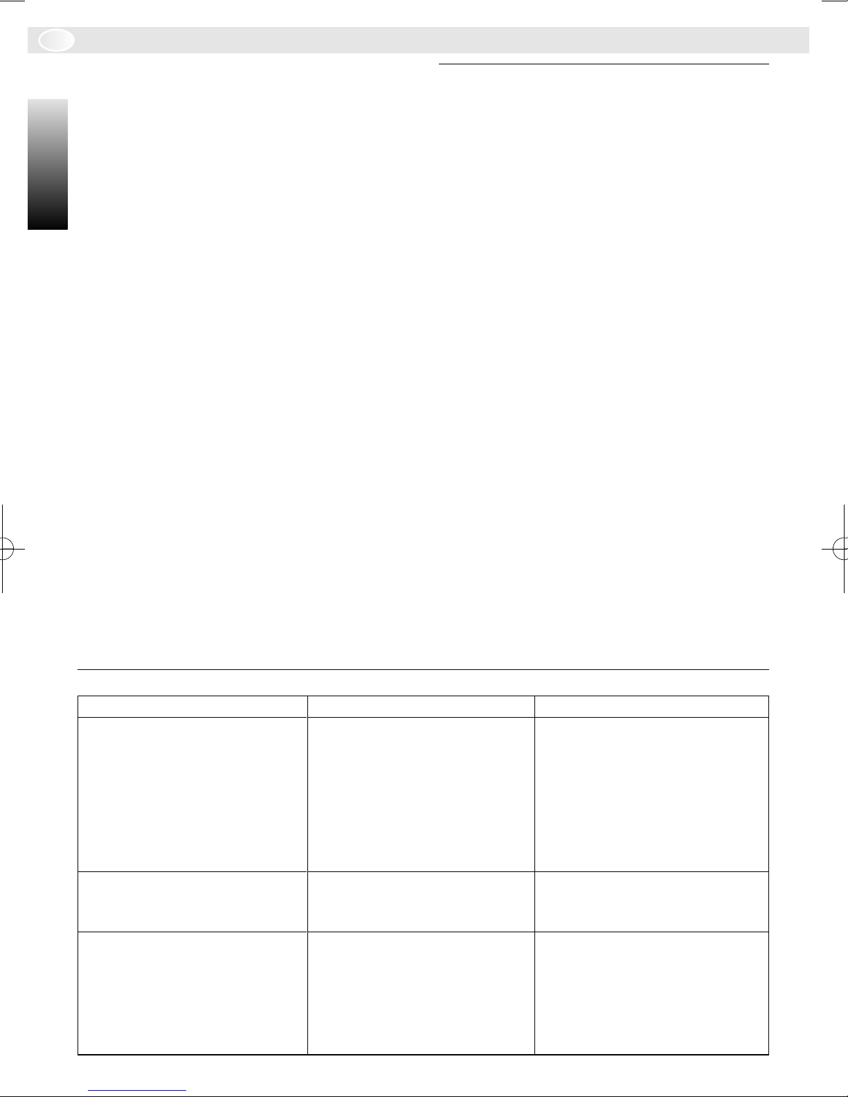
7 Fehlersuche
Fehler
eingestellte Raumtemperatur
wird nicht erreicht
eingestellte Raumtemperatur
wird überschritten
zu große Raumtemperaturschwankungen
6
Ursache
Kesselthermostat am Heizgerät zu niedrig eingestellt
oder
Thermostatventile im Montageraum des Reglers installiert
Montageort des Reglers
ungünstig, z. B. Außenwand,
Fensternähe usw.
zeitweilige Einwirkung von
Fremdwärme auf den Regler,
z. B. Sonneneinstrahlung,
Raumbeleuchtung, TV oder
Kamin usw.
Abhilfe
Kesselthermostat höher einstellen
oder
Thermostatventile ganz öffnen oder ausbauen
besseren Montageort wählen
besseren Montageort wählen
Page 7
TRQ 21 W
GB
1 Application
The TRQ 21 W is a room thermostat with
continuous output for controlling the Junkers
gas heating equipment listed in to .
116
This room thermostat with timer has proven
effective with heaters for single story living
quarters with an area of up to approx. 80m
The thermostat complies with the legal regulations.
The TRQ 21 W is not suitable for buildings
with floor heating or air conditioning.
2 Technical Data
Height 82 mm
Width 165 mm
Depth 42 mm
Rated voltage DC 24 V
Rated current 0.01 A
Controlling range 6 °C … 30 °C
Minimum Temperature 0.05 K/min
change rate
Thermostat output Continuous
2.5 V … 24 V
Permissible ambient
temperature 0 °C … 35 °C
temperature of the complete heating system.
The radiators installed in the room should
not be equipped with thermostatic valves.
It is more effective to install hand valves that
can be preset so that the output of the radiator in the room where the TRQ 21 W is
2
mounted can be set as low as possible.
.
English
English
Select a mounting location on an interior wall
if possible and take care that neither drafts
nor heat radiation can affect the thermostat.
Adequate space must be provided beneath
the thermostat so that the air in the room can
circulate unrestricted through the ventilation
openings (crosshatched area in ). Observe
the recommended distances in .
2
2
4.2 Attaching the Thermostat
Remove the top part of the thermostat (a)
from the base (b) for mounting. This is done
by prying open the housing with a screwdri-
1
ver ( ).
The base (b) of the TRQ 21 W can either be
mounted with two screws (d) to a standard
flush connection box (c) of 55 mm diameter
4
( ) or mounted directly on the wall with
plugs (6 mm) and screws (3.5 mm dia., oval
head) ( ). Use the enclosed drilling templa-
5
te for this purpose.
Operating reserve 50 h
Protection class III
Testing class IP 20
With VDE symbol
3 Safety Instructions
The TRQ 21 W room thermostat is
connected directly to the gas heating
equipment. Do not connect the thermostat to the 230 V mains.
Use the TRQ 21 W only in conjunction
with the Junkers gas heating equipment
listed in to .
116
4 Installation
4.1 General
The selection of a suitable mounting location
is important for the control quality of the
room thermostat. The room in which it is
mounted must be suitable for controlling the
4.3 Electrical Connection
The TRQ 21 W room thermostat is opera-
ted with a direct current voltage of 24V that
is provided by the gas heater over a three-
conductor connecting cable. The control sig-
nal to the heater is also conducted over this
cable.
To prevent interference, this cable must be
laid separately from lines carrying 230 V or
400 V. If external inductive influences can
be expected, for example from power ca-
bles, a shielded cable must be used.
7
Page 8
GB
TRQ 21 W
Use electrical cable of the type NYM with the
following conductor cross section:
Cable length: Cross section:
to 20 m
to 30 m
more than 30 m
English
English
2
2
2
0.75 to 1.5 mm
1.00 to 1.5 mm
1.50 mm
2
Make certain that the cable is voltage-free
and then connect the thermostat with the
three-conductor cable to the gas heater according to the connection plan ( to ).
116
4.4 Putting into Operation
After the electrical cable is connected, insert
the top part of the thermostat (a) onto the
base (b), and put the gas heater into operati-
on.
5 Operation
To set the switching times, remove the cover
(e) of the timer ( ).
The TRQ 21 W room thermostat has the folowing control elements ( and ):
e Cover
f Mode switch
g Temperature setting knob - normal
mode
h Temperature setting knob - reduced
mode
i Plexiglas disk with printed clock hand
j 7-Day ring
k Storage for reserve riders
l Riders in red or blue
1
31
5.1 Mode Switch (f)
The following operating modes are possible:
Automatic switching between normal
2
2
and reduced modes at the times set on
the timer.
Normal mode: Continuous regulation
of the room temperature to the value
set with the knob (g).
Reduced mode: Continuous regulation
of the room temperature to the value
set with the knob (h).
5.2 Temperature Setting Knobs (g) and (h)
With these setting knobs, the desired room
temperatures for normal mode (g) or redu-
ced modes (h) are set. The temperature ran-
ge of each is from 6 to 30 °C.
5.3 Timer
With the selection of the appropriate opera-
ting mode, the timer makes possible the au-
tomatic switching between normal and redu-
ced modes. The shortest switching interval
(closest distance between two riders on the
7-day ring ) is two hours. The positioning ac-
curacy (distance between two adjacent posi-
tions on the 7-day ring) is 30 min.
5.3.1 Setting the Time
Turn the Plexiglas disk with the printed minu-
te hand (i) to set the actual time of day. Turn
the disk only in the clockwise direction. The
7-day ring (j) must not be turned. Observe
that the clock runs in 7-day operation. The
time setting (24 hr and weekday) can be
read off of the 7-day ring (j) at the time mar-
ker (m).
m Time marker for 7-day ring
n Brief operating instructions:
In the compartment on the right side of
the base, a small instruction manual
(JU 1007) can be found. It contains all
essentials for operation in brief form.
8
5.3.2 Setting the Switching Times
• Red rider = Normal mode.
• Blue rider = Reduced mode.
For correct operation of the timer, the riders
must be positioned alternately in red/blue se-
quence.
Stick the red and blue riders (l) for each day
at the desired position of the 7-day ring (j).
Riders that are not used remain in the stora-
ge position (k).
Page 9
TRQ 21 W
GB
5.3.3 Operating Reserve
After at least three days of operation from
the commercial power source, the timer has
an operational reserve available of approx.
50 hours. During this period, the timer continues to run on a rechargeable battery.
Take care that the power supply is not interrupted for longer than 50 hours (also when
the heater is switched off). Deep discharging
shortens the service life of the rechargeable
battery!
6 Tips for Saving Energy
Switch off the heater before ventilating the
room. Always ventilate briefly but intensively.
Avoid continuous ventilation.
A reduction in the room temperature by 1°C
can save up to 5 % of the energy used. Do
not allow the room temperature to sink below
15° C, however, since strong heating up
consumes more energy than uniform hea-
ting.
With good insulation of the building, it is pos-
sible that the reduced temperature setting is
not reached. Energy is saved, however, sin-
ce the heater remains switched off. In this
case, the switching time for reduced mode
can possibly be set earlier.
For subsequent installation of a thermostat
in a room with thermostatically controlled ra-
diators, the thermostatic valves in this room
must be opened completely. Otherwise, the
thermostatic valves restrict the heating alt-
hough the heater is switched on continuous-
ly.
English
English
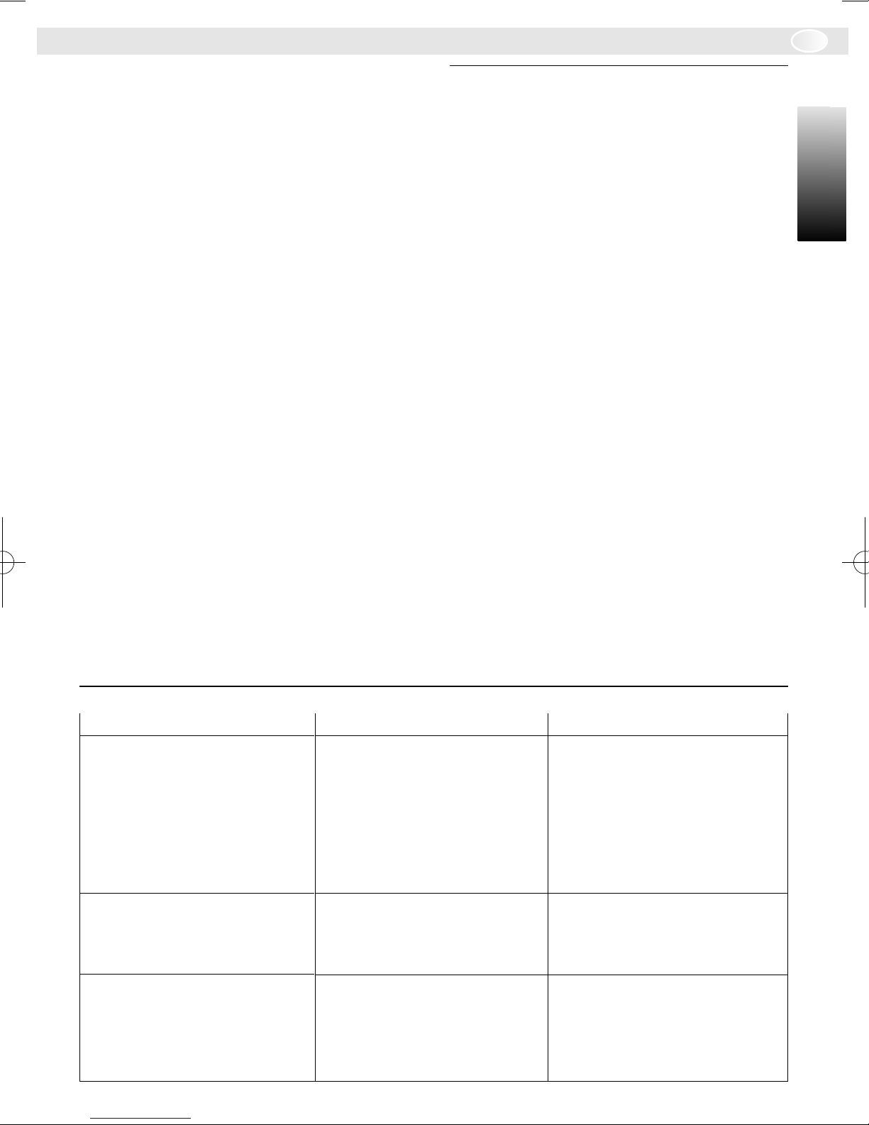
7 Error Localisation
Error
Room temperature setting is
not achieved.
Room temperature setting is
exceeded.
Room temperature variations
too large.
Cause
Boiler thermostat on the heater is set too low.
or
Thermostatic valves are installed in the room where the
thermostat is mounted.
Mounting position of the thermostat is unfavourable, for
example, exterior wall, near
a window, etc.
Intermittent effect of external
warmth on the thermostat,
e.g., sunshine, room lighting,
TV or fireplace, etc.
Corrective Action
Set boiler thermostat higher.
or
Open thermostat valves completely or remove.
Select a better mounting location.
Select a better mounting location.
9
Page 10
F
TRQ 21 W
1 Utilisation
Le TRQ 21 W est un thermostat d'ambiance modulable conçu pour réguler la puissance des chaudières JUNKERS
énumérées sur les schémas à .
116
Ce thermostat d'ambiance équipé d'une hor-
Français
Français
loge programmable s'est avéré très fiable et
performant avec les installations de chauffage pour appartements (jusqu'à 80 m
2
nagés dans des immeubles à plusieurs étages. Il satisfait aux dispositions légales en
vigueur.
Le TRQ 21 W ne convient pas aux appartements équipés d'un chauffage par le sol.
2 Caractéristiques techniques
Hauteur 82 mm
Largeur 165 mm
Profondeur 42 mm
Tension nominale CC 24 V
Courant nominal 0,01 A
Plage de réglage 6 °C … 30 °C
Variation de temp. 0,05 K/min
minimale
Sortie de sortie modulante,
2,5 V … 24 V
Plage de temp.
d’utilisation 0 °C … 35 °C
Autonomie 50 h
Classe de protection III
Catégorie de protection IP 20
Ce produit a obtenu
le certificat VDE
3 Conseils de sécurité
Le thermostat d'ambiance TRQ 21 W
doit être directement branché sur la
chaudière. Ne jamais brancher le thermostat sur le réseau 230 V (cela causerait sa destruction irrémédiable).
Ne mettre en oeuvre le TRQ 21 W
qu'en association avec les chaudières
JUNKERS énumérées sur les schémas
116
à .
) amé-
4 Montage
4.1 Généralités
Le choix de l'emplacement du thermostat est
important. La température de la pièce dans
laquelle le thermostat est installée doit être
représentative de celle de l'ensemble du lo-
gement considéré. Les radiateurs du local
où est installé le thermostat d'ambiance ne
doivent pas être munis de robinets thermost-
atiques.
Une solution utilisant de simples robinets
préréglés est préférable: la capacité de
réglage de la puissance des radiateurs au
niveau de la pièce dans laquelle le thermost-
at est installée doit être aussi réduite que
possible.
Monter le thermostat si possible sur un mur
intérieur et s'assurer qu'aucun courant d'air
ou flux thermique ne puisse influencer le
thermostat. L'air ambiant doit pouvoir circuler
librement sous le thermostat et à travers les
ouïes de refroidissement de l'appareil: main-
tenir libre le domaine hachuré sous l'appareil
et respecter les côtes minimales recomman-
dées (cf. figure ).
4.2 Fixation du thermostat d'ambiance
Pour fixer le thermostat sur un mur, désoli-
dariser et séparer le thermostat (a) de son
socle (b) en faisant levier entre les deux élé-
ments avec l'extrémité d'un tournevis (cf. fi-
gure ).
1
Le socle (b) du TRQ 21 W peut être fixé
soit à l'aide de deux vis (d) sur un boîtier de
distribution encastrée ((c), ø = 55 mm) du
commerce ( ), soit directement à l'aide de
chevilles (6 mm) et de vis à tête goutte de
suif (ø = 3,5 mm, cf. figure ). Utiliser pour
cette dernière solution le gabarit de perçage
fourni.
4.3 Raccordement électrique
Le thermostat d'ambiance TRQ 21 W doit
être alimenté par une tension continue de
24 V fournie par la chaudière via une gaine
électrique à trois fils qui sert simultanément
à envoyer le signal de régulation du ther-
mostat vers la chaudière.
2
4
5
10
Page 11

TRQ 21 W
F
Il convient d'éviter le parasitage de cette ligne électrique. Poser cette ligne séparément
des autres lignes de 230 V ou 400 V. Si
des perturbations inductives (proximité de lignes hautes tensions) sont à craindre,
procéder au blindage de la ligne 24 V.
Utiliser un câble électrique du type NYM disposant de la section de conducteur suivante:
Longeur de câble: section:
jusqu’à 20 m 0,75 jusqu’à 1,5 mm
jusqu’à 30 m 1,00 jusqu’à 1,5 mm
à partir de 30 m 1,50 mm
2
2
2
S'assurer que la ligne en question n'est pas
sous tension et relier le thermostat à la
chaudière via un câble électrique trois fils
conformément au plan de câblage (cf. schémas à ).
116
4.4 Mise en service
Après avoir procédé aux câblages nécessaires, remonter le thermostat (a) sur le socle
(b) et mettre la chaudière en marche.
5 Utilisation
n Notice condensée:
La notice condensée est rangée dans
le logement prévu à cet effet sur la face
latérale droite du socle (b). On y trouvera un résumé des instructions et informations essentielles à la mise en
oeuvre du TRQ 21 W.
5.1 Commutateur de dérogations (f)
On dispose des modes de fonctionnement
suivants:
Fonctionnement automatique. Passage
automatique du mode "diurne" au mode
"nocturne" et inversement aux heures
programmées à l'horloge.
Fonctionnement normal "diurne". Régulation permanente de la température
ambiante sur la base de la valeur définie via la molette (g).
Fonctionnement "nocturne" ou "économique". Régulation permanente de la
température ambiante sur la base de la
valeur définie via la molette (h).
5.2 Molettes de réglage de la température (g) et (h)
Français
Français
Pour modifier les horaires de commutation
du thermostat d'ambiance, retirer le couvercle (e) de l'horloge programmable (figure ).
1
Le thermostat d'ambiance TRQ 21 W dispose des éléments de commande suivants
(figures et ):
31
e Couvercle
f Commutateur de dérogations
g Molette de réglage de la température
en mode normal (mode "diurne")
h Molette de réglage de la température
en mode "abaissement de la température" ("nocturne" ou "économique")
i
Disque de plexiglas, avec aiguille gravée
j Disque de programmation hebdomadai-
re
k Logement pour cavaliers non utilisés
l Cavalier rouge ou bleu
La molette (g), respectivement: (h), sert à définir la température ambiante souhaitée en
mode de fonctionnement normal ("diurne"), respectivement: en mode de fonctionnement "nocturne" ou "économique". Plage de réglage autorisée par ces 2 molettes: de 6°C à 30°C.
5.3 Horloge programmable
L'horloge programmable permet de définir
les heures à partir desquelles le thermostat
doit commuter entre le mode "diurne" et le
mode "nocturne" et inversement de manière
automatique, lorsque le commutateur de
dérogation est en position "fonctionnement
automatique". La plus petite plage de commutation qu'il est possible de définir, (lorsque deux cavaliers sont positionnés directement l'un à côté de l'autre sur le disque hebdomadaire) est égale à 2 heures. La résolution horaire du disque hebdomadaire est,
elle, égale à 30 minutes.
m Marque horaire de disque de program-
mation hebdomadaire
11
Page 12

F
TRQ 21 W
5.3.1 Définition de l'heure courante
Faire tourner le disque de plexiglas (i) sur lequel est gravée une aiguille, de manière à ce
que cette dernière affiche l'heure courante.
Ne faire tourner le disque que dans le sens
des aiguilles d'une montre. Ne pas faire tourner le disque de programmation hebdoma-
Français
Français
daire (j). L'heure et le jour de la semaine
sont indiqués sur le disque (j) par le repère
(m).
5.3.2 Programmation de l'horloge
• Cavalier rouge = Mode normal "diure".
• Cavalier bleu = Mode "économique",
"nocturne".
En fonction du rythme de vie suivi, positionner les cavaliers rouges et bleus (l) sur le
disque hebdomadaire (j) pour chaque jour
de la semaine.
Poser les cavaliers rouge et bleu (l) aux horaires souhaités sur le disque horaire (j).
Laisser les cavaliers non utilisés dans le logement (k) qui leur est réservé.
5.3.3 Autonomie
Après au moins trois jours de fonctionnement, l'horloge programmable dispose d'une
autonomie de fonctionnement par rapport à
l'alimentation électrique extérieure d'environ
50 heures. Pendant cette période, l'horloge
programmable consomme l'électricité que lui
fournit un accumulateur intégré.
Veiller à ce que l'alimentation électrique ne
soit pas interrompue plus de 50 heures
(même lorsque le chauffage est éteint): les
déchargements complets de l'accumulateur
réduisent sa durée de vie.
6
Arrêter le chauffage avant d'aérer les pièces.
Aérer toujours brièvement mais intensément
(les fenêtres grandes ouvertes). Eviter d'aérer trop longtemps ou en permanence.
Un abaissement de la température d'un seul
degré peut se traduire par une économie
d'énergie pouvant aller jusqu'à 5%. Ne pas
laisser la température descendre sous 15°C:
un réchauffement brutal et rapide d'un local
consomme plus d'énergie que l'approvisionnement thermique nécessaire au maintien d'une température moyenne.
Dans une pièce dont les radiateurs sont pilotés par un thermostat et dans laquelle on a
procédé à l'installation ultérieure d'un robinet
thermostatique, il convient d'ouvrir totalement les thermostats. Les robinets thermostatiques auraient sinon tendance à brider le
chauffage tandis que la chaudière fonctionnerait en permanence.
Conseils d'économie d'énergie
7 Pannes - Causes - Remèdes
Pannes
La température ambiante
souhaitée n'est pas atteint
La température ambiante
souhaitée est dépassée
Différence de températures
trop élevée
12
Causes
Position de l'aquastat de la
chaudière trop faible
ou
Robinets thermostatiques
montés sur les radiateurs du
local témoin
Emplacement du thermostat
mal choisi (exemple: murs
extérieurs, proximité de
fenêtres, etc.)
Des sources thermiques telles que fenêtres, soleil, éclairage ambiant, cheminée, poste de télévision, etc. influencent le thermostat.
Remèdes
Augmenter la position de l'aquastat
ou
Ouvrir ou bien enlever complètement les robinets thermostatiques
Choisir un meilleur emplacement pour le thermostat
Choisir un meilleur emplacement pour le thermostat
Page 13

TRQ 21 W
E
1 Utilización
El TRQ 21 W es un regulador de temperatura ambiente con salida continua para gobernar los calefactores de gas Junkers detallados en a .
116
Este regulador de temperatura ambiente con
reloj programador se ha acreditado en calefacciones individuales en viviendas con superficies de hasta aprox. 80 m
2
y cumple
con las prescripciones legales.
El TRQ 21 W no es adecuado para instala-
ciones con calefacción por suelo radiante o
suelos climatizados.
2 Datos técnicos
Altura 82 mm
Anchura 165 mm
Profundidad 42 mm
Tensión nominal C.C. 24 V
Corriente nominal 0,01 A
Margen de regulación 6 °C … 30 °C
Velocidad mínima de 0,05 K/min
cambio de temperatura
Salida de regulador continua,
2,5 V … 24 V
Temperatura ambiente
admisible 0 °C … 35 °C
Reserva de funcionamiento 50 h
te es la elección de un lugar de montaje
apropiado. El recinto de montaje debe adecuarse para la regulación de temperatura de
la instalación de calefacción completa. Los
radiadores allí instalados no deben estar
equipados con válvulas termostáticas.
Más adecuado es el montaje de válvulas
manuales con preajuste para que el ajuste
de potencia del radiador en el recinto de
montaje del TRQ 21 W sea mínima.
Seleccione como lugar de montaje en lo posible una pared interior y cuide que ni corrientes de aire ni radiaciones térmicas afecten
al regulador. Debajo del regulador debe haber suficiente espacio para que el aire ambiente pueda circular libremente por los orificios de ventilación (área rayada en ). Ob-
2
serve las medidas de separación recomendadas en .
2
4.2 Sujeción del regulador
Separe para su montaje la parte superior del
regulador (a) del zócalo (b). Apalanque para
ello la carcasa con un atornillador ( ).
1
El zócalo (b) del TRQ 21 W puede montarse
o bien con dos tornillos (d) sobre un caja
bajo enlucido (c) de Ø55 mm usual en el comercio ( ) o puede fijarse con tacos (6 mm)
4
y tornillos (Ø 3,5 mm, cabeza de lenteja) directamente a la pared ( ). Emplee la plantil-
5
la para taladrar adjunta.
Español
Español
Clase de protección III
Tipo de protección IP 20
Aprobación por VDE
3 Indicaciones de seguridad
El regulador de temperatura ambiente
TRQ 21 W se conecta directamente a
la calefacción de gas. No conecte el regulador a la red de 230 V.
Emplee el TRQ 21 W sólo junto con los
calefactores de gas Junkers detallados
en a .
116
4 Montaje
4.1 Generalidades
Importante para una buena calidad de regulación del regulador de temperatura ambien-
4.3 Conexión eléctrica
El regulador de temperatura ambiente
TRQ 21 W opera con una tensión continua
de 24V suministrada por la calefacción de
gas por un cable de conexión de tres conductores. A través de este cable se transfiere además la señal de mando al calefactor.
A fin de evitar perturbaciones debe tenderse
este cable separado de cables portadores
de tensión de 230 V o 400 V respectivamente. Si se preven influencias externas de tipo
inductivo, p. ej. debido a corrientes de alta
intensidad o similares, debe emplearse un
cable apantallado.
13
Page 14

E
TRQ 21 W
Emplee cable eléctrico del tipo NYM con las
siguientes secciones:
Longituda de cable: Sección:
hasta 20 m 0,75 hasta 1,5 mm
hasta 30 m 1,00 hasta 1,5 mm
desde 30 m 1,50 mm
Español
Español
2
Asegúrese que el cable se encuentre libre
de tensión, y conecte el regulador con un
cable de tres conductores de acuerdo al esquema de conexión ( a ) a la calefac-
116
ción de gas.
4.4 Puesta en marcha
Monte la parte superior del regulador (a) de-
spués de conectar los conductores eléctricos al zócalo (b), y ponga la calefacción en
marcha.
5 Manejo
Para ajustar el tiempo de conexión debe quitarse la caperuza (e) del reloj de programación ( ).
El regulador de temperatura ambiente
TRQ21 W dispone de los siguientes elementos de mando ( y ):
e Cubierta
f Conmutador de modo de operación
g Rueda de ajuste de temperatura; fun-
h Rueda de ajuste de temperatura; fun-
i Disco de plexiglás con indicador
j Anillo de 7 días
k Almacén con caballetes de reserva
l Caballete rojo o azul
m Marca horaria para anillo de 7 días
n Instrucciones breves de manejo:
1
31
cionamiento normal
cionamiento de descenso
En el compartimiento al lado derecho
del zócalo se encuentran las instrucciones breves de manejo del JU 1007.
Aquí se indica de forma somera lo más
importante sobre su manejo.
5.1 Conmutador de modo de operación (f)
Son posibles los siguientes modos de ope-
2
2
ración:
Cambio automático entre funcionamiento normal y funcionamiento de
descenso según tiempos ajustados en
reloj de programación.
Funcionamiento normal: regulación
permanente de la temperatura ambiente seleccionada en la rueda de ajuste
(g)
Funcionamiento de descenso: regulación permanente de la temperatura
ambiente seleccionada en la rueda de
ajuste (h).
5.2 Ruedas de ajuste de temperatura
(g) y (h)
Con estas ruedas de ajuste se selecciona la
temperatura ambiente deseada para un funcionamiento normal (g) o bien para un funcionamiento de descenso (h). El margen de
temperatura abarca en cada caso de 6 a
30 °C.
5.3 Reloj de programación
Al haber seleccionado el correspondiente
modo de operación, el reloj de programación
permite la conmutación automática entre
funcionamiento normal y funcionamiento de
descenso. El tiempo de conexión mínimo
(separación más corta entre dos caballetes
del anillo de 7 días) es de 2 h. La precisión
de señalización (separación entre dos posiciones de inserción vecinas en el anillo de 7
días) es de 30 min.
5.3.1 Ajuste de la hora
Para ajustar la hora actual, gire el disco de
plexiglás con el indicador (i). El disco sólo
debe girarse en dirección de las agujas del
reloj. No debe girarse el anillo de 7 días (j).
Observe Vd. que el reloj funciona con un
servicio de 7 días. La hora ajustada (24 h y
día de la semana) puede Vd. determinarla
en la marca horaria (m) del anillo de 7 días
(j).
14
Page 15

TRQ 21 W
E
5.3.2 Ajuste del tiempo de conexión
• Caballete rojo = funcionamiento normal.
• Caballete azul = funcionamiento de descenso.
Para obtener un funcionamiento correcto del
reloj de programación deben colocarse los
caballetes rojo/azul alternativamente.
Inserte Vd. los caballetes (l) rojos y azules
para cada día en la posición deseada en el
anillo de 7 días (j).
Los caballetes no precisados pueden guardarse en el almacén (k).
5.3.3 Reserva de funcionamiento
Tras una conexión a la alimentación de corriente de mínimo 3 días, el reloj de programación dispone de una reserva de funcionamiento de aprox. 50 horas. El reloj funciona durante este periodo con un acumulador.
Cuide que la alimentación de corriente no
quede interrumpida durante un lapso mayor
a 50 horas (incluso con la calefacción desconectada). ¡Las descargas totales reducen
la vida útil del acumulador!
6 Consejos para el ahorro de
energía
Desconecte la calefacción antes de airear el
recinto. Ventile sólo breve pero intensamente. Evite la aireación permanente.
La reducción de la temperatura ambiente en
1°C puede llegar a ahorrar hasta 5 % de
energía. No deje descender sin embargo la
temperatura ambiente por debajo de los
15°C, ya que un posterior fuerte calentamiento consume más energía que una
aportación uniforme de calor.
Si el edificio dispone de buen aislamiento
térmico no llegará a alcanzarse posiblemente la temperatura de descenso ajustada.
Aun así se ahorra energía ya que la calefacción se mantiene desconectada. En estos
casos puede Ud. anticipar eventualmente el
momento de conexión en el modo de descenso.
En caso de montaje posterior de un regulador en un recinto con radiadores regulados
por termostato éstos deben abrirse completamente. Las válvulas termostáticas actuarían de lo contrario a pesar de que la calefacción esté continuamente conectada.
Español
Español
7 Búsqueda de averías
Avería
No se alcanza la temperatura
ambiente ajustada
Se sobrepasa la temperatura
ambiente ajustada
Excesivas variaciones de la
temperatura ambiente
Causa
Ajuste demasiado bajo del
termostato de caldera en calefactor
o
Válvulas termostáticas instaladas en recinto de montaje
del regulador
Lugar de montaje de regulador inadecuado, p. ej. pared
exterior, próximo a una ventana, etc.
Influjo temporal de fuentes
de calor externas sobre el
regulador, p. ej. radiación
solar, iluminación, TV o chimenea etc.
Solución
Ajustar más alto el termostato
de caldera
o
Abrir completamente o desmontar válvulas termostáticas
Elegir lugar de montaje más
adecuado
Elegir lugar de montaje más
adecuado
15
Page 16

I
TRQ 21 W
1 Applicazione
Il TRQ 21 W è un regolatore della temperatura ambiente a funzionamento modulante
per il comando degli apparecchi di riscaldamento a gas Junkers (figure fino a ).
Questo regolatore della temperatura am-
Italiano
Italiano
biente con comando ad orologeria si è affermato nel campo della regolazione di temperatura di appartamenti con una superficie
abitabile fino a c. 80 m
2
e risponde inoltre
alle prescrizioni legislative in materia.
Il TRQ 21 W non è indicato per impianto di
riscaldamento a pavimento o per pavimento
climatico.
2 Dati tecnici
Altezza 82 mm
Larghezza 165 mm
Profonditá 42 mm
Tensione nominale DC 24 V
Corrente nominale 0,01 A
4 Montaggio
4.1 Considerazioni generali
Importante per un corretto funzionamento è
116
la scelta del luogo di installazione. Esso
deve essere rappresentativo per la regolazione della temperatura di tutto l'impianto di
riscaldamento. Sui radiatori presenti nel locale di installazione non vi deve essere montata alcuna valvola termostatica.
E' consigliabile montare delle valvole per la
regolazione manuale equipaggiate con preregolazione affinché si possa impostare correttamente la potenza del radiatore posto nel
luogo di installazione del TRQ 21 W.
Montare il regolatore possibilmente su una
parete interna e cercare di evitare che eventuali correnti d'aria od irradiazioni di calore
influenzino il regolatore. Sotto il regolatore
deve esserci spazio sufficiente per una libera circolazione dell'aria attraverso le apposite feritoie (zona tratteggiata in ). Tenere
presente le distanze minime consigliate .
2
2
Campo di regolazione 6 °C … 30 °C
Velocità minima di varia- 0,05 K/min
zione della temperatura
Uscita di regolazione modulante,
2,5 V … 24 V
Temperatura ambiente
consentita 0 °C … 35 °C
Riserva di marcia 50 h
Classe di protezione III
Classe di collaudo IP 20
Omologazione VDE
3 Indicazioni di sicurezza
Il regolatore della temperatura ambiente
TRQ 21 W viene collegato direttamente all'apparecchio di riscaldamento a
gas. Non collegare il regolatore della
temperatura alla rete di corrente di 230
V.
Utilizzare il regolatore TRQ 21 W soltanto in connessione con gli apparecchi
di riscaldamento a gas Junkers riportati
(figure fino a ).
116
4.2 Installazione del regolatore della
temperatura
Per installare il regolatore della temperatura
bisogna staccare la parte superiore (a) dalla
base (b). Facendo leva con un cacciavite,
aprire il corpo del regolatore della temperatura ( ).
1
La base (b) del TRQ 21 W può essere installata o con due viti (d) in una cassetta incassata con un Ø 55 mm ( ) comunemente re-
4
peribile sul mercato (c) oppure può essere
installata con tasselli (6 mm) e viti (Ø 3,5
mm, vite a testa con calotta) direttamente
sulla parete ( ). Utilizzare la dimetta fornita
5
a corredo per eseguire i relativi fori.
4.3 Collegamento elettrico
Il regolatore della temperatura ambiente
TRQ 21 W funziona a corrente a tensione
continua di 24V che viene alimentata attraverso una linea di collegamento a tre fili
dall'apparecchio di riscaldamento a gas. Attraverso questa linea passa anche il segnale
di comando per l'apparecchio di riscaldamento.
16
Page 17

TRQ 21 W
I
Al fine di evitare anomalie di funzionamento,
è necessario che questa linea di collegamento venga installata in modo che sia separata da linee di alimentazione da 230 V o
risp. da 400 V. Se vi è la possibilità di influssi esterni induttivi come, p.e., da cavi per
corrente forte o simili, è necessario eseguire
una schermatura della linea di collegamento.
Utilizzare cavi elettrici del tipo NYM con i seguenti diametri :
Lunghezza Diametro:
della linea:
fino a 20 m 0,75 fino a 1,5 mm
fino a 30 m 1,00 fino a 1,5 mm
da 30 m 1,50 mm
2
2
2
Assicurarsi che la linea non sia sottoposta a
tensioni ed eseguire il collegamento del regolatore della temperatura con l'apparecchio
di riscaldamento a gas utilizzando un cavo a
tre fili conformemente allo schema di colle-
gamento ( fino a ).
116
4.4 Messa in esercizio
Dopo aver eseguito i collegamenti di alimentazione elettrica, riapplicare la parte superiore del regolatore della temperatura (a) sulla
base (b) e mettere l'apparecchio di riscaldamento a gas in esercizio.
5 Comando
Per impostare gli intervalli di funzionamento,
togliere la cuffia di copertura (e) del cronoruttore ( ).
Il regolatore di temperatura ambiente TRQ
21 W dispone dei seguenti elementi di comando ( e ):
e Cuffia di copertura
f Selettore di programma
g Selettore della temperatura funzio-
1
31
namento normale
l Cavaliere rosso o blu
m Marcatura dei tempi dell’anello 7 giorni
n Breve istruzione per l'uso: Nella sede
sulla destra della base si trova una breve istruzione per l'uso JU 1007 in cui si
trovano riportati schematicamente i comandi necessari per l'esercizio.
5.1 Selettore di programma (f)
Sono possibili le seguenti selezioni di programma:
Passaggio automatico: all'ora impostata
sull'orologio, dal funzionamento normale si passa al funzionamento a temperatura ridotta.
Funzionamento normale: Regolazione
costante della temperatura ambiente in
base al valore impostato tramite il relativo selettore (g).
Funzionamento a temperatura ridotta:
Regolazione costante della temperatura ambiente in base al valore impostato
tramite il relativo selettore (h).
5.2 Selettori della temperatura (g) e (h)
Con questi selettori della temperatura viene
impostata la temperatura ambiente desiderata per il funzionamento normale (g) o risp.
per il funzionamento a temperatura ridotta
(h). Il campo di impostazione della temperatura va da 6 fino a 30 °C.
5.3 Orologio
La commutazione permette, a seconda del
tipo di esercizio preselezionato, un passaggio automatico dal funzionamento normale al funzionamento a riscaldamento ridotto. La distanza più breve di commutazione (distanza minima tra i cavalieri sull'anello
7 giorni) è di 2 ore. La precisione di inserimento (distanza tra due posizioni vicine di
inserimento sull'anello 7 giorni) è di 30 min.
5.3.1 Impostazione dell'ora
Italiano
Italiano
h Selettore della temperatura funzio-
namento a temperatura ridotta
i Piastra di plexiglas con lancetta
j Anello 7 giorni
k Sede per cavaliere di riserva
Girare il disco di plexiglas con la lancetta stampata (l), per impostare l'ora attuale. Il disco può
essere girato soltanto in senso orario. Non è
permesso girare l'anello 7 giorni (j). Tenere
presente che l'orologio funziona a cicli di 7 giorni.
17
Page 18

I
TRQ 21 W
E' possibile rilevare l'ora impostata (24 ore e
giorno della settimana) sull'anello 7 giorni (j)
alla marcatura dell'indicazione dei tempi (m).
5.3.2 Impostazione dell'intervallo di funzionamento
• Cavaliere rosso = Funzionamento nor-
Italiano
Italiano
• Cavaliere blu = Funzionamento a ris-
Perché il selettore funzioni correttamente è
necessario che i cavalieri siano inseriti alternativamente rosso/blu.
Inserire i cavalieri rossi e blu (l) per ogni singolo giorno nella relativa posizione dell'anello 7 giorni (j).
Cavalieri non impiegati possono essere inseriti nella relativa sede (k).
5.3.3 Riserva di marcia
Dopo un esercizio di almeno tre giorni con
collegamento alla rete di alimentazione,
l'orologio di commutazione ha una riserva di
marcia di c. 50 ore. Durante questo periodo
l'orologio continua a funzionare attraverso un
accumulatore.
Fare attenzione a che l'alimentazione elettrica non venga a mancare per un periodo superiore a 50 ore (anche se il riscaldamento
dovesse essere messo fuori esercizio).
male.
caldamento ridotto.
Scaricamenti completi limitano la durata
dell'accumulatore!
6
Consigli per risparmiare energia
Spegnere il riscaldamento prima di arieggiare. Arieggiare sempre per breve tempo ed
in maniera intensiva. Evitate di arieggiare in
maniera continua.
Abbassando di 1°C la temperatura del locale
è possibile risparmiare energia fino ad un
5%. Evitare comunque che la temperatura
dell'ambiente scenda sotto i 15°C, perché un
riscaldamento forte implica un consumo di
energia maggiore rispetto ad un riscaldamento uniformemente distribuito.
In caso di una buona isolazione dell'edificio
è possibile che l'impostata temperatura ridotta non possa essere raggiunta. Ciononostante si risparmia energia perché il riscaldamento resta spento. In questo caso è
possibile impostare eventualmente su un valore più alto il punto di commutazione per il
funzionamento in riduzione.
In caso di montaggio postumo di un regolatore della temperatura in un locale in cui vi sono
radiatori regolati con termostati è necessario
che i termostati dei radiatori che si trovano nel
locale siano completamente aperti. Le valvole
termostatiche chiuderebbero anche se il riscaldamento fosse sempre acceso.
7 Ricerca di anomalie
Anomalia
Non viene raggiunta la temperatura ambiente impostata
Viene superata la temperatura ambiente impostata
Oscillazioni troppo forti della
temperatura ambiente
18
Causa
Il termostato della caldaia
all'apparecchio di riscaldamento è impostato su un valore troppo basso
oppure
nel locale in cui è stato installato il regolatore vi sono
valvole termostatiche
Il luogo in cui è stato installato il regolatore non è adeguato, p.e. parete esterna, vicino ad una finestra, ecc.
Influenze temporanee di fonti
di calore esterne sul regolatore, p.e. raggi solari, illuminazione del locale, TV, camino, ecc.
Intervento
Impostare il termostato della
caldaia su valori più alti
oppure
aprire completamente o togliere le valvole termostatiche
Scegliere un luogo di installazione più adatto
Scegliere un luogo di installazione più adatto
Page 19

TRQ 21 W
NL
1 Gebruik
De TRQ 21 W is een ruimtetemperatuurregelaar met continusturing voor het regelen
van de in tot vermelde gasverwar-
116
mingsapparaten.
Deze ruimtetemperatuurregelaar met tijd-
schakelklok is geschikt voor etageverwarmingen tot ca. 80 m
2
woonoppervlak en vol-
doet aan de wettelijke voorschriften.
Voor installaties met vloerverwarmingen of
klimaatvloeren is de TRQ 21 W niet geschikt.
2 Technische gegevens
Hoogte 82 mm
Breedte 165 mm
Diepte 42 mm
Nominale spanning DC 24 V
Nominale stroom 0,01 A
Regelbereik 6 °C … 30 °C
Minimale temperatuur- 0,05 K/min
veranderingssnelheid
Regelaaruitgang continu,
2,5 V … 24 V
Toegestane omgevingstemperatuur 0 °C … 35 °C
Loopreserve 50 h
Veiligheidsklasse III
Isolatiesoort IP 20
VDE-waarmerk verleend
montageruimte moet geschikt zijn voor de
temperatuurregeling van de complete verwarmingsinstallatie. Op de daar geïnstalleerde verwarmingsradiatoren mogen geen thermostaatkranen gemonteerd zijn.
Het is beter om handbediende kranen met
voorinstelling te plaatsen en om hiermee het
vermogen van de verwarmingsradiatoren in
de montageruimte van de TRQ 21 W zo laag
mogelijk in te stellen.
Kies als montageplaats indien mogelijk een
binnenmuur en zorg er voor dat er geen
tocht of warmtestraling op de regelaar kan
inwerken. Onder de regelaar moet voldoende plaats aanwezig zijn om de lucht in de
ruimte ongehinderd door de ventilatieopening te laten circuleren (gearceerd gebied in
2
). Neem de geadviseerde afstandsmaten
2
in in acht.
4.2 Bevestiging van de regelaar
Trek voor de montage het bovengedeelte
van de regelaar (a) van de grondplaat (b). Til
daarvoor de behuizing met een schroevedraaier op ( ).
1
De grondplaat (b) van de TRQ 21 W kan
met twee schroeven (d) op een normale inbouwstopcontactdoos (c) van ø 55 mm worden gemonteerd ( ) of met pluggen (6 mm)
4
en schroeven (ø 3,5 mm, lenskop) rechtstreeks in de muur verankerd worden ( ). Ge-
5
bruik daarvoor het boorsjabloon in de verpakking.
4.3 Elektrische aansluiting
Nederlands
Nederlands
3 Veiligheidsvoorschriften
De ruimtetemperatuurregelaar
TRQ 21 W wordt rechtstreeks aan het
gasverwarmingsapparaat aangesloten.
Sluit de regelaar niet aan op 230 V.
Gebruik de TRQ 21 W uitsluitend in
combinatie met de in tot vermelde Junkers gasverwarmingsapparaten.
4 Montage
4.1 Algemeen
Belangrijk voor de goede regelfunctie van de
ruimtetemperatuurregelaar is de keuze van
een geschikte plaats voor de montage. De
De ruimtetemperatuurregelaar TRQ 21 W
werkt op een gelijkspanning van 24 V, die
wordt geleverd door het gasverwarmingsapparaat via een verbindingskabel met drie
aders. Via deze kabel wordt ook het stuursignaal naar het verwarmingsapparaat geleid.
116
Om storingen te voorkomen, moet deze kabel gescheiden van kabels van 230 of 400 V
worden geïnstalleerd. Indien inductieve invloeden van buitenaf kunnen optreden, bijv.
door sterkstroomkabels, moet de kabel worden afgeschermd.
19
Page 20

NL
TRQ 21 W
Gebruik elektrische kabels van het type
NYM met de volgende kabeldiameters:
Kabellengte: Diameter:
tot 20 m 0,75 tot 1,5 mm
tot 30 m 1,00 tot 1,5 mm
meer dan 30 m 1,50 mm
Nederlands
Nederlands
Overtuigt u zich er van dat de kabel span-
2
ningsvrij is en verbind daarna de regelaar
met een drie-aderige kabel volgens het
aansluitschema ( tot ) met het gasver-
116
warmingsapparaat.
4.4 Ingebruikname
Steek het bovengedeelte van de regelaar (a)
na het aansluiten van de elektrische kabels
op de grondplaat (b) en stel het gasverwarmingsapparaat in werking.
5 Bediening
Om de schakeltijden in te stellen, verwijdert u
het afschermkapje (e) van de schakelklok
1
().
De ruimtetemperatuurregelaar TRQ 21 W
bezit de volgende bedieningselementen (
3
en ).
e Afschermkapje
f Functieschakelaar
g Temperatuurdraaiknop normaal bedrijf
h Temperatuurdraaiknop verlaagd bedrijf
i Plexiglas schijf met wijzer
j 7-dagen-ring
k Depot met reservesteekruiters
Automatisch wisselen tussen normaal
bedrijf en verlaagd bedrijf op de met de
schakelklok ingestelde tijden.
2
Normaal bedrijf: continuregeling van de
ruimtetemperatuur volgens de met de
2
draaiknop (g) ingestelde waarde.
Verlaagd bedrijf: continuregeling van
de ruimtetemperatuur volgens de met
de draaiknop (h) ingestelde waarde.
5.2
Temperatuurdraaiknoppen (g) en (h)
Met deze draaiknoppen stelt u de gewenste
ruimtetemperatuur in voor normaal bedrijf (g)
en verlaagd bedrijf (h). Het temperatuurbereik ligt tussen 6 en 30 °C.
5.3 Schakelklok
Met behulp van de schakelklok kan er bij
een bepaalde ingestelde functie automatisch
worden omgeschakeld tussen normaal bedrijf en verlaagd bedrijf. De kortste schakelperiode (kleinste afstand tussen twee steekruiters op de 7-dagen-ring) bedraagt 2 uur.
De schakelnauwkeurigheid (afstand tussen
twee naburige steekposities op de 7-dagen-
1
ring) bedraagt 30 min.
5.3.1 Instellen van de tijd
Draai aan de plexiglas schijf met wijzer (i)
om de actuele tijd in te stellen. De schijf mag
uitsluitend in de richting van de wijzers van
de klok worden gedraaid. De 7-dagen-ring
(j) mag niet gedraaid worden. Denk er om
dat de klok loopt volgens het 7-dagensysteem. De ingestelde tijd (24 h en dag van de
week) kunt u aflezen op de tijdmarkering (m)
van de 7-dagen-ring (j) aflezen.
l Rode en blauwe steekruiters
m Tijdmarkering voor 7-dagen-ring
n Korte gebruiksaanwijzing:
In het vak aan de rechterzijde van de
grondplaat bevindt zich de korte gebruiksaanwijzing JU 1007. Hier vindt u
alles wat voor de bediening van belang
is.
5.1 Functieschakelaar (f)
De volgende functies zijn mogelijk:
20
5.3.2 Instellen van de schakeltijden
• Rode steekruiters = normaal bedrijf.
• Blauwe steekruiters = verlaagd bedrijf.
Om de schakelklok correct te laten werken,
moeten de rode en blauwe steekruiters afwisselend worden aangebracht.
Steek de rode en blauwe steekruiters (l)
voor iedere dag op de gewenste positie op
de 7-dagen-ring (j).
Niet benodigde steekruiters in de depots (k)
laten zitten.
Page 21

TRQ 21 W
NL
5.3.3 Loopreserve
De schakelklok beschikt na een gebruik van
drie dagen op het stroomnet over een loopreserve van ca. 50 uur. Gedurende deze
tijd loopt de klok op een accu.
Zorg er voor dat de stroomvoorziening niet
langer dan 50 uur wordt onderbroken (ook
wanneer de verwarming uit staat). Volledig
ontladen verkort de levensduur van de accu.
6 Tips voor energiebesparing
Zet de verwarming uit voordat u de ruimte
lucht. Lucht altijd kort, maar intensief. Lucht
nooit continu.
Een verlaging van de ruimtetemperatuur met
1°C kan een energiebesparing van 5 %
opleveren. Laat de ruimtetemperatuur echter
nooit dalen beneden 15°C, aangezien een
sterke verhitting meer energie verbruikt dan
een gelijkmatige warmtetoevoer.
Bij een goede warmte-isolatie van het gebouw wordt soms de ingestelde lage temperatuur niet bereikt. Toch wordt energie bespaard, omdat de verwarming uitgeschakeld
blijft. U kunt in dit geval het schakeltijdstip
voor verlaagd bedrijf vervroegen.
Indien een ruimtetemperatuurregelaar achteraf wordt ingebouwd in een ruimte met
door een thermostaat geregelde verwarmingsradiatoren, moeten de thermostaatkranen in deze ruimte geheel geopend worden.
Anders sluiten de thermostaten, hoewel de
verwarming voortdurend ingeschakeld is.
Nederlands
Nederlands
7 Opsporen van storingen
Storingen
Ingestelde ruimtetemperatuur
wordt niet bereikt
Te grote ruimtetemperatuurschommelingen.
Oorzaak
Ketelthermostaat op verwarmingsapparaat te laag ingesteld
of
Thermostaatventielen in
montageruimte van de regelaar geïnstalleerd
Montageplaats van de regelaar niet gunstig, bijv. buitenmuur, vlakbij raam etc.
Tijdelijke inwerking van storende warmte op de regelaar, bijv. zonnestralen, verlichting, TV of schoorsteen
Oplossing
Ketelthermostaat hoger instellen
of
Thermostaatventielen helemaal openen of demonteren
Betere montageplaats kiezen.
Betere montageplaats kiezen.
21
Page 22

DK
TRQ 21 W
1 Anvendelse
TRQ 21 W er en rumtermostat med kontinuerlig udgang til regulering af de Junkers
gaskedler, som vises fra til .
116
Denne rumtermostat med kontaktur har vist
sig velegnet til etageopvarmning med indtil
Dansk
Dansk
ca. 80 m
2
boligareal og opfylder lovens be-
stemmelser.
TRQ 21 W er ikke velegnet til gulvvarmean-
læg eller klimagulve.
2 Tekniske data
Høje 82 mm
Bredde 165 mm
Dybde 42 mm
Driftsspænding DC 24 V
Strømforbrug 0,01 A
Reguleringsområde 6 °C … 30 °C
Minimal temperatur- 0,05 K/mi
ændrings-hastighed
4 Montering
4.1 Generelt
Af hensyn til reguleringskvaliteten for rumtermostaten er det vigtigt, at denne placeres på
et egnet sted. Monteringsrummets temperatur skal kunne danne baggrund for regulering af det samlede varmeanlæg. På radiatorerne i monteringsrummet bør der ikke være
monteret termostatventiler.
Bedre er det at montere håndventiler med
forindstilling, således at radiatorernes ydelse
i monteringsrummet for TRQ 21 W kan indstilles så knap som mulig.
Som monteringssted bør der vælges en indervæg, hvor termostaten ikke udsættes for
hverken træk eller varmestråling. Under regulatoren skal der være tilstrækkelig friplads
til at rumluften uhindret kan cirkulere gennem
ventilationsåbningerne (skraveret felt i ).
Bemærk de anbefalede afstandsmål i .
4.2 Fastgøring af termostat
2
2
Reguleringsudgang konstant,
2,5 V … 24 V
Tilladelig
rumtemperatur 0 °C … 35 °C
Gangreserve 50 h
Beskyttelsesklasse III
Tæthedsgrad IP 20
Tildelt VDE-mærket
3 Sikkerhedsforskrifter
Rumtermostaten TRQ 21 W tilsluttes
direkte på gaskedlen. Tilslut ikke termostaten til et strømnet med 230 V.
Benyt kun TRQ 21 W i forbindelse
med de kedelmodeller fra Junkers, som
er opført fra til .
116
Før montering skal apparatets overdel (a)
løsnes og trækkes af soklen (b). Huset løftes
op med en skruetrækker ( ).
1
Soklen (b) kan enten monteres på en almindelig indmuringsdåse (c) Ø 55 mm med 2
skruer ( ) eller fastgøres direkte i væggen
5
( ) med dyvler (6 mm) og skruer (Ø 3,5
4
mm, linsehoved). Hvis sidstnævnte løsning
vælges, kan vedlagte boreskabelon anvendes til opmærkning af borehuller.
4.3 Elektrisk tilslutning
TRQ 21 W er en 24 V lavspændingstermostat og tilsluttes gaskedlen med et 3 leder
kabel. Via dette kabel føres også styresignalet til kedlen.
Termostaten må ikke tilsluttes 230 V resp.
400 V for at undgå fejl. Hvis der forventes induktive ydre indflydelser som f.eks. stærkstrømskabler eller lign., skal kablet monteres
med beskyttelse.
22
Page 23

TRQ 21 W
DK
Benyt elektrokabler af typen NYM med følgende tværsnitsareal:
Kabellængde: Tværsnit:
indtil 20 m 0,75 til 1,5 mm
indtil 30 m 1,00 til 1,5 mm
fra 30 m 1,50 mm
2
2
2
Vær sikker på, at kablet er spændingsfrit, og
forbind reguleringen med gaskedlen med et 3
leder kabel iht. tilslutningsskema ( til ).
116
4.4 Idrifttagning
Stik reguleringens overdel (a) efter tilslutning
af de elektriske kabler på soklen (b), og tag
gaskedlen i drift.
5 Betjening
Før indstilling af kontakturet skal dækpladen
(e) på kontakturet ( ) fjernes.
Rumtermostaten TRQ 21 W råder over følgende betjeningselementer ( og ):
e Dækplade
f Driftskontakt
g Temperaturvælger "normal drift"
h Temperaturvælger "sænket drift"
i Pleksiglasrude med påtrykt viser
j 7-dage-ring
k Depot for reserve-indstikspinde
l Indstikspinde rød eller blå
m Tidsmarkering for 7-dage-ring
j Kort betjeningsvejledning:
I rummet på den højre side af soklen
findes den korte betjeningsvejledning
JU 1007, som indeholder de vigtigste
informationer mht. betjening.
1
31
5.1 Driftskontakt (f)
Følgende driftsarter er mulige:
Automatisk skift mellem "normal drift"
og "sænket drift" efter de på kontakturet
indstillede tidspunkter.
Normal drift: Konstant regulering af
rumtemperaturen efter den på temperaturvælgeren (g) indstillede temperatur.
Sænket drift: Konstant regulering af
rumtemperaturen efter den på temperaturvælgeren (h) indstillede værdi.
5.2 Temperaturvælger (g) og (h)
Den ønskede rumtemperatur for "normal
drift" (g) resp. "sænket drift" (h) kan indstilles
mellem 6 og 30 °C.
5.3 Kontaktur
Kontakturet gør det muligt at skifte automatisk om mellem "normal drift" og "sænket
drift" iht. den valgte driftsart. Den korteste
koblingsafstand (mindste afstand mellem to
stikryttere på 7-dage-ringen) er 2 timer. StiknØjagtigheden (afstand mellem to stikpositioner, som er placeret ved siden af hinanden på 7-dage-ringen) er 30 min.
5.3.1 Indstilling af kontaktur
Pleksiglasskiven med den påtrykte viser (i)
drejes højre om, indtil det aktuelle tidspunkt
er indstillet. 7-dage-ringen (j) må ikke drejes.
Vær opmærksom på, at uret går i 7-dagedrift. Det indstillede ur (24 h og ugedag) kan
aflæses på 7-dage-ringen (j) på tidsmarkeringen (m).
5.3.2 Indstilling af ind- og udkoblingstider
• Røde indstikspinde = normal drift.
• Blå indstikspinde = sænket drift.
Dansk
Dansk
En korrekt drift kræver, at indstikspindene
indstikkes skiftevis i rækkefølgen rød/blå.
Stik den røde og den blå stikrytter (l) for hver
dag på den ønskede position på 7-dage-ringen (j).
Ikke benyttede indstikspinde opbevares i depotet (k).
23
Page 24

DK
TRQ 21 W
5.3.3 Gangreserve
Efter mindst 3 dages drift via strømnettet råder kontakturet over en gangreserve på ca.
50 timer. I denne tid arbejder uret videre via
en akkumulator.
Vær opmærksom på, at strømforsyningen
Dansk
Dansk
ikke afbrydes længere end 50 timer (også
når varmen er afbrudt). Meget afladte akkumulatorer forringer akkumulatorens levetid!
6 Energispareråd
Sluk for varmen, før udluftning finder sted.
Ved udluftning anbefales en kort, men kraftig
udluftning af boligen. Undgå at have et vindue vedvarende åbent eller på klem.
En sænkning af rumtemperaturen med 1 °C
kan spare op til 5 % energi. Lad ikke temperaturen synke til under 15 °C, da stærk opvarmning forbruger mere energi, end en
jævn varmetilførsel.
For bygninger, der er godt isoleret, vil rumtemperaturen muligvis ikke falde til den indstillede sænkningstemperatur. Der spares
dog alligevel energi, da varmen forbliver udkoblet i sænkningsperioden. I dette tilfælde
kan koblingstidspunktet for sænket drift
eventuelt indstilles tidligere.
Ved senere montering af en rumtermostat i
et rum med termostatregulerede radiatorer
skal termostaterne åbnes helt i dette rum.
Termostatventilerne lukker ellers, selv om
varmen konstant er tændt.
7 Fejlsøgning
Fejl
Indstillet rumtemperatur nås
ikkeIndstillet
Rumtemperatur overskrides.
For store rumtemperatursvingninger.
24
Årsag
Kedeltermostat stillet for lavt
eller
termostatventiler installeret i
termostatens montagerum
Ugunstig placering af termostat, f.eks. på ydervæg eller nær vindue osv.
Termostat påvirkes af fremmedvarme f.eks. solindfald,
rumbelysning, tv eller brændereovn osv.
Afhjælpning
Kedeltermostat stilles højere
eller
termostatventiler åbnes helt
eller demonteres
Bedre egnet placeringssted
findes
Bedre egnet placeringssted
findes
Page 25

TRQ 21 W
P
1 Utilização
O TRQ 21 W é um regulador de temperatura
ambiente com saída permanente para a regulação dos aquecedores a gás Junkers
apresentados entre e .
116
Este regulador de temperatura ambiente
com relógio digital deu bons resultados no
caso de aquecimentos de andares com até
aprox. 80 m
2
de superfície habitável e corre-
sponde às normas legais.
Para equipamentos com aquecimentos de
solo ou solos aclimatizados o TRQ 21 W
não é apropriado.
2 Dados técnicos
Altura 82 mm
Largura 165 mm
Profundidade 42 mm
Tensão nominal D.C. 24 V
Corrente nominal 0,01 A
Amplitude de regulação 6 °C … 30 °C
Velocidade mínima de 0,05 K/min
alteração de temperatura
Saída do regulador constante,
2,5 V … 24 V
Temperatura ambiente
permitida 0 °C … 35 °C
Reserva de funcionamento 50 h
Clase de protecção III
Tipo de protecção IP 20
Designação VDE concedida
3 Indicações de segurança
O regulador de temperatura ambiente
TRQ 21 W é ligado directamente ao
aquecedor a gás. Não ligue o regulador
à rede de 230-V.
Utilize o TRQ 21 W somente em ligação com os aquecedores a gás Junkers apresentados de a .
116
4 Montagem
4.1 Generalidades
Importante para a qualidade de regulação
do regulador de temperatura ambiente é a
escolha de um local de montagem apropriado. O recinto de montagem deve ser apropriado para o regulamento de temperatura
de todo o equipamento de aquecimento.
Nos aquecedores ali instalados não devem
estar montadas válvulas termostáticas.
É preferível montar válvulas manuais com
pré-regulação, para que a potência dos
aquecedores no recinto de montagem do
TRQ 21 W possam ser ajustados no mínimo
possível.
Escolha um local de montagem, de preferência uma parede interior e tomar atenção para
que o regulador de temperatura ambiente
não sofra a acção directa de correntes de ar
nem de irradiação de calor. Por baixo do regulador de temperatura ambiente deve existir
espaço suficiente para que o ar possa circular livremente através da abertura de ventilação (área tracejada ). Observe as distâncias recomendadas .
4.2 Fixação do regulado
Para a montagem, puxe a parte superior do
regulador (a) da basel (b). Para isto abra a
carcaça com uma chave de fendas ( ).
A base (b) do TRQ 21 W pode ser montada
com dois parafusos (d) numa caixa embuti-
da usual no mercado (c) com Ø de 55 mm
4
( ) ou com cavilhas (6 mm) e parafusos (Ø
3,5 mm, cabeça lenticular) directamente na
parede ( ). Utilize o escantilhão fornecido
5
anexo.
4.3 Ligação eléctrica
O regulador de temperatura ambiente
TRQ21 W funciona com tensão contínua de
24V, que é fornecida pelo aquecedor a gás
através de um cabo de ligação de três fios.
Através desta ligação também é transmitido
o sinal de comando para o aquecedor.
2
2
1
Porto
Porto
25
Page 26

P
TRQ 21 W
Para evitar avarias, estes cabos de ligação
devem ser instalados separadamente dos
cabos de ligação de 230 V ou 400 V. Se puder contar com influências externas inductivas como por exemplo devido à cabos de
alta tensão, ou semelhantes, será necessário blindar o cabo.
Porto
Porto
Utilize cabos eléctricos do tipo NYM com os
seguintes cortes transversais:
Longituda de cable: Sección:
até 20 m 0,75 até 1,5 mm
até 30 m 1,00 até 1,5 mm
a partir de 30 m 1,50 mm
2
Assegure-se de que os cabos estejam livres
de tensão, e ligue o regulador com um cabo
de três fios de acordo com o plano de ligação ( até ) ao aquecedor.
116
4.4 Funcionamento
Após ligar à rede, coloque a parte superior
do regulador (a) sobre a base (b) e ligue o
radiador.
5 Comando
Para ajustar os períodos de comutação retire a tampa de cobertura (e) do relógio ( ).
O regulador de temperatura ambiente
TRQ21 W possui os seguintes elementos de
comando ( e ):
e Tampa de cobertura
f Interrruptor de tipos de funcionamento
g Botão de ajuste da temperatura para
funcionamento normal
31
5.1 Interruptor de tipos de funcionamento (f)
São possíveis os seguintes tipos de funcionamento:
Funcionamento alternado: Alternação
automática entre funcionamento normal e função de redução de acordo
com os períodos programados no relógio.
2
2
Funcionamento normal: Regulação
contínua da temperatura ambiente de
acordo com o valor ajustado no botão
rotativo (g).
Função de redução: Regulação contínua da temperatura ambiente de acordo com o valor ajustado no botão rotativo (h).
5.2 Botões rotativos (g) e (h)
Com estes botões rotativos é possível ajustar a temperatura ambiente desejada para
o funcionamento normal (g) ou para a
função de redução (h). A temperatura pode
ser regulada de 6 a 30 °C.
5.3 Relógio
1
Seleccionando-se o tipo de funcionamento
correspondente, o relógio possibilita a comutação automática entre funcionamento
normal e função de redução. A menor distância de comutação (menor distância entre dois cursores no anel de 7 dias) é de 2
horas. A exactidão (distância entre duas posições de cursores vizinhos no anel de 7
dias) é de 30 min.
h Botão de ajuste da temperatura para
função de redução
i Plexiglas com indicador aplicado
j Anel de 7 dias
k Depósito com cursor de reserva
l Cursor vermelho ou azul
m Marcação de tempo para anel de 7 dias
n Breve instrução de serviço:
No compartimento, na parte direita da
base encontra-se uma breve instrução
de serviço para o JU 1007. Aqui estão
em apontamentos os pontos principais
para o comando.
26
5.3.1 Ajustar a hora
Girar o disco de plexiglas com o indicador
(i), para ajustar a hora actual. O disco só
deve ser girado no sentido dos ponteiros do
relógio. O anel de 7 dias (j) não deve ser girado. Observe que o relógio funcione num
ritmo de 7 dias. A hora ajustada (24 h e dia
da semana) pode ser lida no anel de 7 dias
(j) na marcação de tempo (m).
Page 27

TRQ 21 W
P
5.3.2 Ajustar os períodos de comutação
• Cursores vermelhos = Funcionamento
normal
• Cursores azuis = Função de
redução
Para o funcionamento correcto do relógio é
necessário que os cursores estejam introduzidos alternadamente, vermelho/azul.
Coloque os cursores vermelhos e azuis (l)
para cada dia na posição desejada no anel
de 7 dias (j).
Cursores que não são necessitados devem
ser colocados no depósito (k).
5.3.3 Reserva de funcionamento
O relógio possui após no mínimo 3 dias de
funcionamento ligado à rede, uma reserva
de funcionamento de aprox. 16 horas. Durante uma falta de corrente a indicação apaga. Após a volta de corrente dentro do
período mencionado, todas as funções
estarão novamente à disposição.
Observe que o abastecimento de rede não
seja interrompido por mais do que 16 horas
(mesmo que o aquecimento esteja desligado). Descarregamento totais diminuem o
tempo de duração do acumulador integrado!
6 Instruções sobre economia
de energia
Desligue o aquecimento antes de arejar. Renovar o ar sempre de forma intensa, mas
breve. Evite uma renovação de ar constante.
Uma redução da temperatura ambiente por
1°C pode poupar até 5 % de energia. Contudo não permita que a temperatura ambiente seja inferior a 15 °C, pois um aquecimento intensivo gasta mais energia do que um
aquecimento regular.
Se o edifício tiver um bom isolamento, a redução para a temperatura seleccionada não
será, possivelmente, alcançada. Apesar de
tudo será poupada energia porque o aquecimento permanece desligado. Neste caso
deve-se ajustar a hora de comutação para a
função de redução eventualmente para uma
hora mais cedo.
No caso de montagem posterior de um regulador de temperatura ambiente num recinto com um aquecimento regulado por um
termostato, os termostatos deste recinto devem ser totalmente abertos. Caso contrário
as válvulas dos termostatos estrangulam
apesar do aquecimento estar constantemente ligado.
Porto
Porto
7 Localização de defeitos
Avaria Motivo Solução
A temperatura seleccionada O termostato no aquecimento Regular o termostato do
não é atingida está regulado para um valor aquecimento para um valor
muito baixo mais elevado
ou
Existem válvulas termostáti-- Abrir totalmente ou desmoncas montadas no local de- tar as válvulas termostáticas
montagem do regulador de
temperatura ambiente
A temperatura ambiente regu- O local de montagem do re- Seleccionar um local de monlada é excedida gulador de temperatura am- tagem mais favorável
biente é desfavorável, p. ex.
parede exterior ou proximidade de janela, etc.
Oscilações de temperatura- Efeito temporário de calor Seleccionar um local de monambiente muito elevadas sobre o regulador, p. ex.: tagem mais favorável
acção directa de raios solares,
iluminação local, televisão
ou chaminé, etc.
27
Page 28

1 2 3 4F B 1 2 3 41 2 3
ST8 ST9 ST10
DC 24V
1 2 3 4
TRQ 21W
12 4
12 4
CERA STAR ZR/ZWR18/24-3…
CERA STAR PLUS ZR/ZWR18/24-4…
CERA NOX ZV/ZWV 20 A
CERA mini ZR/ZSR 8/11-3…
CERA mini PLUS ZSR 11-4
EURO … ZWE…A…
1 2 3 4
TRQ 21W
12 4
12 4
1 2 4 5 7 8 9
DC 24V
SUPRA STAR KS/KSN/KNS…-7E
1 2 3 4
TRQ 21W
12 4
1
Netz
230V/50Hz
24
1 2 4NR
DC 24V
AC 230
N
R1
ZR/ZWR/ZSR…
mini…
CL(N)100
KWR…
DC 24V
1 2 3 4
1 2 3 4
TRQ 21W
12 4
12 4
EURO … ZE/ZWE…K…
ST2
DC 24V
1 2 3 4
TRQ 21W
12 4
12 4
CERA PUR ZSBR/ZWBR 8-25 A
K/KS…-5R…
KS/KSN…-6E
KS…-6EK
1 2 3 4
TRQ 21W
42 1
12 4
4 2 18 7 PL
DC 24V
9
ATF
1112
8 9
6 7
1110
TRQ 21 W
28
Page 29

TRQ 21 W
29
Page 30

TRQ 21 W
30
Page 31

TRQ 21 W
31
Page 32

Bosch Thermotechnik GmbH
Junkersstrasse 20-24
D-73249 Wernau
www.junkers.com
 Loading...