

Page 1
MB LAN
6 720 647 836-00.1O
[de] Installationsanleitung . . . . . . . . . . . . . . . . . . . . . . . . . . . . . . . . . . . . . . 2
[en] Installation instruction. . . . . . . . . . . . . . . . . . . . . . . . . . . . . . . . . . . . . . 5
[fr] Notice d’installation . . . . . . . . . . . . . . . . . . . . . . . . . . . . . . . . . . . . . . . . 8
[it] Istruzioni d’installazione . . . . . . . . . . . . . . . . . . . . . . . . . . . . . . . . . . . 11
[fl] Installatiehandleiding . . . . . . . . . . . . . . . . . . . . . . . . . . . . . . . . . . . . . 14
[et] Paigaldusjuhend . . . . . . . . . . . . . . . . . . . . . . . . . . . . . . . . . . . . . . . . . 17
[lv] Uzstādīšanas instrukcija . . . . . . . . . . . . . . . . . . . . . . . . . . . . . . . . . . . 20
[lt] Montavimo instrukcija . . . . . . . . . . . . . . . . . . . . . . . . . . . . . . . . . . . . . 23
[cs] Návod k instalaci . . . . . . . . . . . . . . . . . . . . . . . . . . . . . . . . . . . . . . . . . 26
[pl] Instrukcja instalacji . . . . . . . . . . . . . . . . . . . . . . . . . . . . . . . . . . . . . . . 29
6 720 802 641 (2012/08)
Page 2
Inhaltsverzeichnis
Inhaltsverzeichnis
1 Symbolerklärung und Sicherheitshinweise . . . . . . . . . . . . . . . 2
1.1 Symbolerklärung . . . . . . . . . . . . . . . . . . . . . . . . . . . . . . . . 2
1.2 Sicherheitshinweise . . . . . . . . . . . . . . . . . . . . . . . . . . . . . 2
2 Angaben zum Produkt . . . . . . . . . . . . . . . . . . . . . . . . . . . . . . . . . 2
2.1 Lieferumfang . . . . . . . . . . . . . . . . . . . . . . . . . . . . . . . . . . . 2
2.2 Reinigung und Pflege . . . . . . . . . . . . . . . . . . . . . . . . . . . . . 2
2.3 Technische Daten . . . . . . . . . . . . . . . . . . . . . . . . . . . . . . . 3
3 Installation . . . . . . . . . . . . . . . . . . . . . . . . . . . . . . . . . . . . . . . . . . . 3
3.1 Montage . . . . . . . . . . . . . . . . . . . . . . . . . . . . . . . . . . . . . . . 3
3.2 Elektrischer Anschluss . . . . . . . . . . . . . . . . . . . . . . . . . . . 3
4 Inbetriebnahme . . . . . . . . . . . . . . . . . . . . . . . . . . . . . . . . . . . . . . . 3
5 Umweltschutz/Entsorgung . . . . . . . . . . . . . . . . . . . . . . . . . . . . . 3
6 Störungen beheben . . . . . . . . . . . . . . . . . . . . . . . . . . . . . . . . . . . . 4
1.2 Sicherheitshinweise
B Landesspezifische Vorschriften und Normen für Installation und
Betrieb beachten!
B Anleitung einhalten, damit die einwandfreie Funktion gewährleistet
wird.
B Produkt nur von einem zugelassenen Fachhandwerker installieren
und in Betrieb nehmen lassen.
B Produkt nicht in Feuchträumen installieren.
B Wärmeerzeuger und weiteres Zubehör entsprechend den zugehöri-
gen Anleitungen installieren und in Betrieb nehmen.
B Produkt ausschließlich in Verbindung mit den aufgeführten Bedie-
neinheiten und Wärmeerzeugern verwenden. Anschlussplan beachten!
B Mitgeliefertes Netzteil zum Anschluss an das 230-V-Netz verwenden.
Zu dieser Anleitung
Die vorliegende Installationsanleitung enthält wichtige Informationen
zur sicheren und sachgerechten Installation, Inbetriebnahme und Wartung des Produktes.
Diese Installationsanleitung richtet sich an den Fachhandwerker, der
aufgrund seiner fachlichen Ausbildung und Erfahrung Kenntnisse im
Umgang mit Elektroinstallation und Heizungsanlagen hat.
2 Angaben zum Produkt
Anhang . . . . . . . . . . . . . . . . . . . . . . . . . . . . . . . . . . . . . . . . . . . . 32
1 Symbolerklärung und Sicherheitshinweise
1.1 Symbolerklärung
Wichtige Informationen
Wichtige Informationen ohne Gefahren für Menschen
oder Sachen werden mit dem nebenstehenden Symbol
gekennzeichnet. Sie werden durch Linien ober- und unterhalb des Textes begrenzt.
Weitere Symbole
Symbol Bedeutung
B Handlungsschritt
Æ Querverweis auf andere Stellen im Dokument oder auf
andere Dokumente
• Aufzählung/Listeneintrag
– Aufzählung/Listeneintrag (2. Ebene)
Tab. 1
Zur Nutzung des vollen Funktionsumfangs benötigen Sie
einen Internetzugang. Hierdurch können zusätzliche
Kosten entstehen.
Zur Steuerung der Anlage mit einem Smartphone benötigen Sie außerdem die kostenpflichtige App
JunkersHome.
• Schnittstelle zwischen der Heizungsanlage und einem Netzwerk
1)
.
(LAN)
• Steuerung und Überwachung einer Anlage mit einem Smartphone
Das MB LAN kann nicht mit dem raumtemperaturgeführten Regler FR 50 kombiniert werden.
• Kombinierbar mit:
– Wärmeerzeugern mit 2-Draht-BUS-Schnittstelle und Reglern
FW.../FR... ab FD 889 (09/2008) mit 2-Draht-BUS-Schnittstelle,
z. B. FW 200
– Modulen für Regler FW.../FR... ab FD 889 (09/2008), z. B. ISM2.
2)
2.1 Lieferumfang
Bild 1, Seite 32:
[1] Modul
[2] Steckernetzteil mit Anschlusskabel (2 m Länge)
[3] LAN-Kabel CAT 5 (2 m Länge)
[4] Beutel mit Montageteilen (Schrauben, Dübel, Anschlussstecker
für 2-Draht-BUS-Schnittstelle)
[5] Installationsanleitung
.
2.2 Reinigung und Pflege
B Bei Bedarf mit einem feuchten Tuch das Gehäuse abreiben. Dabei
keine scharfen oder ätzenden Reinigungsmittel verwenden.
1) Zum Anschluss des Moduls ist ein Router mit einer freien RJ45-Buchse
erforderlich.
2) Unterstützte Geräte entnehmen Sie bitte unserer Homepage.
2
MB LAN – 6 720 802 641 (2012/08)
Page 3
Installation
2.3 Technische Daten
Technische Daten
Abmessungen (B ×H×T) 151×184 ×61mm (weitere Maße
Æ Bild 2, Seite 32)
Maximaler Leiterquerschnitt
2,5 mm
2
(Anschlussklemmen)
Nennspannungen:
• BUS
• Spannungsversorgung
des vModuls
• 12 V bis 15 V DC (verpolungssicher)
• Mitgeliefertes Steckernetzteil
230V AC/7,5 V DC, 700 mA
Schnittstellen • 2-Draht-BUS
• LAN: 10/100 MBit/s (RJ45)
Leistungsaufnahme 1,5 VA
zulässige Umgebungstempe-
0 ... 50 °C
ratur
Schutzart IP20
Tab. 2
3Installation
3.1 Montage
B Abdeckung entfernen (Æ Bild 3, Seite 32)
B Modul montieren (Æ Bild 4, Seite 32)
B Modul fixieren (Æ Bild 5, Seite 32)
3.2 Elektrischer Anschluss
Anschlüsse und Schnittstellen
Legende zu Bild 6, Seite 33:
7,5 V DC Anschluss Netzteil
HT Anschluss 2-Draht-BUS-System
LAN Anschluss LAN (RJ45)
RESET RESET-Taste
Tüllen vormontieren und Kabel anschließen
B Tüllen dem Kabeldurchmesser entsprechend öffnen und an einer
Seite einschneiden (Æ Bild 7, Seite 33).
B Tüllen montieren und Kabel anschließen (Æ Bild 8, Seite 33).
Anschluss der BUS-Verbindung
B BUS-Teilnehmer mit zwei BUS-Anschlüssen in Reihe schalten
(Æ Bild 6, Seite 33) oder BUS-Teilnehmer [B] mit einer Verteilerdose [A] in Sternschaltung (Æ Bild 9, Seite 33) verbinden.
Wenn die maximale Kabellänge der BUS-Verbindung zwischen allen BUS-Teilnehmern überschritten wird, ist die
Inbetriebnahme der Anlage nicht möglich.
Rundfunk- und Fernsehgeräte, Amateurfunkstationen, Mikrowellengeräte, usw.).
B Abdeckung montieren und mitgeliefertes Netzteil einstecken.
4 Inbetriebnahme
Wenn bei der Inbetriebnahme weder die BUS-Verbindung noch die LAN-Verbindung hergestellt ist, leuchtet
die LED am Modul dauerhaft rot.
Der Router muss wie folgt eingestellt sein:
• DHCP aktiv
• Ports 5222 und 5223 nicht gesperrt
• Freie IP-Adresse vorhanden
• Adressfilterung (MAC-Filter) auf das Modul angepasst.
Das Modul bezieht automatisch eine IP-Adresse vom Router. In den
Grundeinstellungen des Moduls sind der Name und die Adresse des Ziel servers hinterlegt. Wenn eine Internetverbindung besteht, meldet sich
das Modul automatisch am Junkers-Server an.
Eine Internetverbindung des Routers ist nicht zwingend erforderlich.
Das Modul kann auch ausschließlich im lokalen Netzwerk betrieben werden. In diesem Fall ist kein Zugriff über das Internet auf die Heizungsanlage und kein automatisches Softwareupdate des Moduls möglich.
Beim ersten Starten der App JunkersHome werden Sie aufgefordert,
den werkseitig voreingestellten Loginnamen und das Passwort einzugeben. Diese Logindaten sind auf dem Typschild des Moduls aufgedruckt.
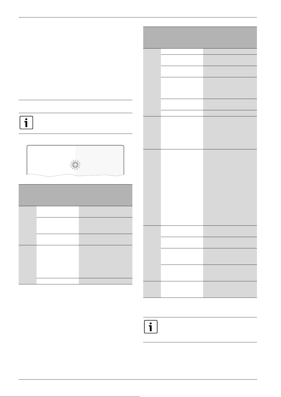
Typschild
Legende zu Bild 10, Seite 33:
[1] Typschild mit Logindaten, MAC-Adresse und Seriennummer
[2] Kodierschalter (ohne Funktion)
Verbindung testen (bei angemeldetem Heizkreis 1)
Sie können prüfen, ob das Modul korrekt mit der Heizungsanlage kommuniziert.
B RESET-Taste (Æ Bild 6, Seite 33) kurz drücken, um die Betriebsart
für Heizkreis 1 am Regler zu ändern.
Das Display des Reglers zeigt die geänderte Betriebsart an (Heizen
oder Sparen ).
B Zum Abschluss des Verbindungstests wieder die gewünschte
Betriebsart einstellen.
Persönliche Einstellungen zurücksetzen (Reset)
Wenn Sie Ihren personalisierten Loginnamen oder Ihr Passwort vergessen haben:
B RESET-Taste (Æ Bild 6, Seite 33) drücken und mindestens 5 Sekun-
den gedrückt halten.
Die werkseitig voreingestellten Logindaten sind wiederhergestellt.
Kabellänge Leiterquerschnitt
≤ 80 m 0,40 mm
≤ 100 m 0,50 mm
≤ 150 m 0,75 mm
≤ 200 m 1,00 mm
≤ 300 m 1,50 mm
2
2
2
2
2
Tab. 3 Gesamtlänge der BUS-Verbindungen
B Um induktive Beeinflussungen zu vermeiden: Alle Kleinspannungska-
bel von Netzspannung führenden Kabeln getrennt verlegen (Mindestabstand 100 mm).
B Bei induktiven äußeren Einflüssen Kabel geschirmt ausführen.
Dadurch sind die elektrischen Leitungen gegen äußere Einflüsse
abgeschirmt (z. B. Starkstromkabel, Fahrdrähte, Trafostationen,
MB LAN – 6 720 802 641 (2012/08)
5 Umweltschutz/Entsorgung
Umweltschutz ist ein Unternehmensgrundsatz der Bosch Gruppe.
Qualität der Erzeugnisse, Wirtschaftlichkeit und Umweltschutz sind für
uns gleichrangige Ziele. Gesetze und Vorschriften zum Umweltschutz
werden strikt eingehalten.
Zum Schutz der Umwelt setzen wir unter Berücksichtigung wirtschaftlicher Gesichtspunkte bestmögliche Technik und Materialien ein.
Verpackung
Bei der Verpackung sind wir an den länderspezifischen Verwertungssystemen beteiligt, die ein optimales Recycling gewährleisten.
Alle verwendeten Verpackungsmaterialien sind umweltverträglich und
wiederverwertbar.
3
Page 4
Störungen beheben
Altgerät
Altgeräte enthalten Wertstoffe, die einer Wiederverwertung zuzuführen
sind.
Die Baugruppen sind leicht zu trennen und die Kunststoffe sind gekennzeichnet. Somit können die verschiedenen Baugruppen sortiert und
dem Recycling oder der Entsorgung zugeführt werden.
6Störungen beheben
Informationen zur Störungsbehebung am Router oder
Smartphone finden Sie in der zugehörigen Anleitung des
Drittanbieters.
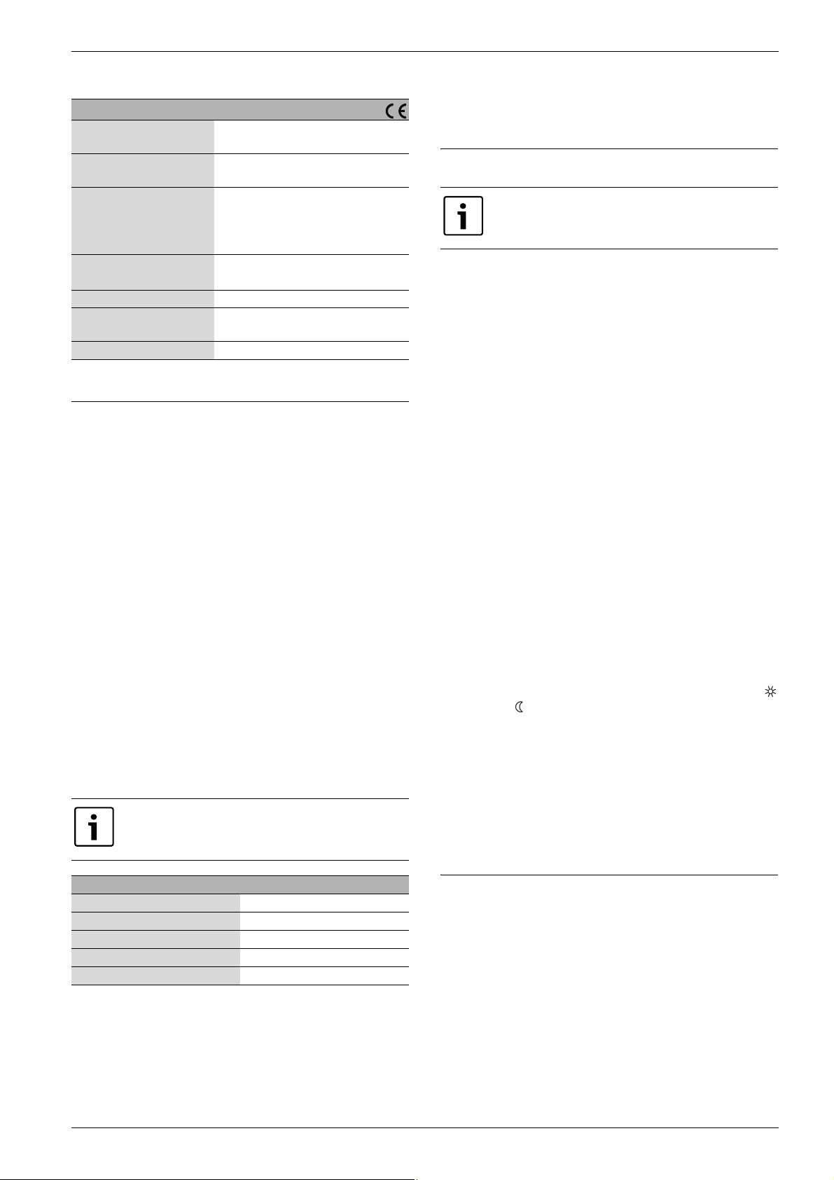
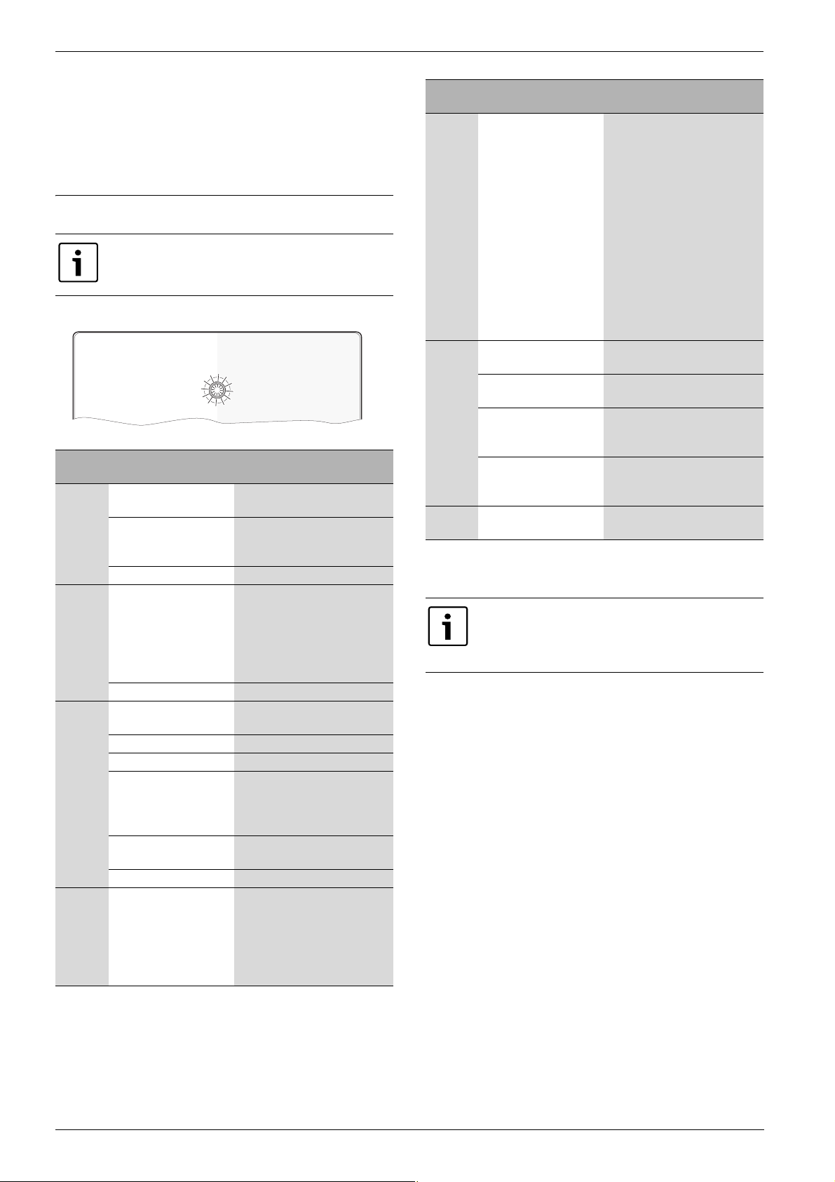
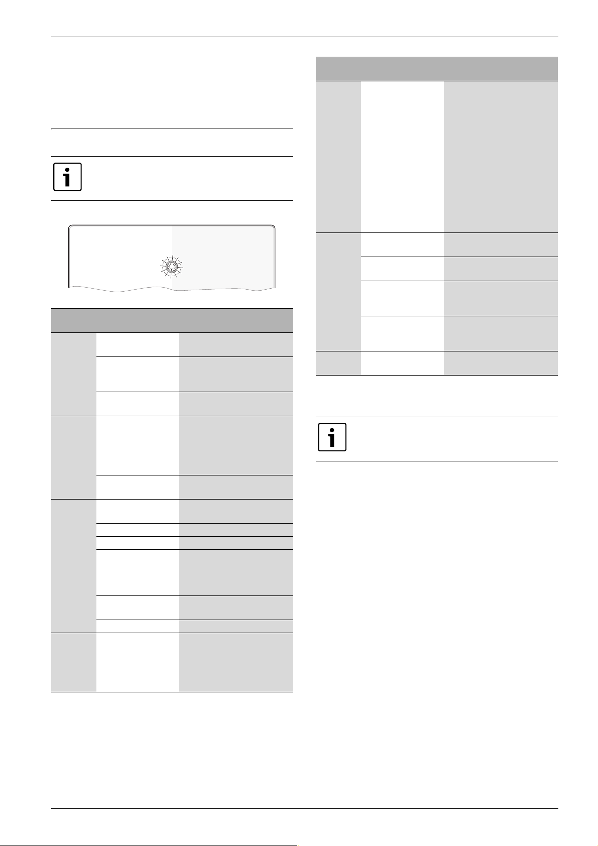
Die Betriebsanzeige zeigt den Betriebszustand des Moduls.
6 720 647 836-01.1o
Betriebsanzeige
dauernd
aus
dauernd
rot
rot
blinkend
abwechselnd rot
und grün
Tab. 4 Störungstabelle
Mögliche Ursache Abhilfe
Spannungsversorgung
unterbrochen.
Anschlusskabel Netzteil
B Spannungsversorgung ein-
schalten.
B Verbindung herstellen.
nicht mit dem Modul verbunden.
Netzteil defekt.
Bei Erstinbetriebnahme
oder Werksreset: Weder
BUS- noch LAN-Verbindung vorhanden.
B Netzteil austauschen.
B Modul von der Spannungsver-
sorgung trennen.
B BUS- und LAN-Verbindung
herstellen.
B Modul erneut in Betrieb neh-
men.
Sonst: Interne Störung
LAN-Kabel nicht ange-
B Modul austauschen.
B LAN-Verbindung herstellen.
schlossen.
Router ist ausgeschaltet.
DHCP ist inaktiv.
Manuell gesetzter MAC-
Filter unterbindet Vergabe der IP-Adresse.
B Router einschalten1).
B DHCP am Router aktivieren1).
B MAC-Filter für die aufge-
druckte MAC-Adresse einstel-
len (Æ Bild 10, [1],
Seite 33).
Keine IP-Adresse für das
Modul frei.
B Konfiguration am Router
überprüfen
1)
.
LAN-Kabel defekt. B LAN-Kabel austauschen.
BUS- und LAN-Verbin-
dung nach Inbetriebnahme getrennt.
B Modul von der Spannungsver-
sorgung trennen.
B BUS- und LAN-Verbindung
herstellen.
B Modul erneut in Betrieb neh-
men.
Betriebsanzeige
dauernd
orange
Mögliche Ursache Abhilfe
LAN-Verbindung
besteht; kein Zugang
zum Junkers-Server über
das Internet.
grün
blinkend
Wärmeerzeuger ausgeschaltet.
Modul nicht am BUS-System angeschlossen.
maximale Kabellänge
BUS-Verbindung überschritten
Kurzschluss oder Kabelbruch in der BUS-Verbindung.
dauernd
Keine Störung Normalbetrieb
grün
Tab. 4 Störungstabelle
1) Siehe Anleitung des Drittanbieters.
Störungen mit Auswirkung auf die Funktionalität der App
werden auch in der App dargestellt (z. B. keine Verbindung zum XMPP Server, keine Verbindung zum MB LAN,
falsches Passwort, ...).
B Modul für 10 Sekunden von
der Spannungsversorgung
trennen und erneut in Betrieb
nehmen.
-oder-
B Internetverbindung herstel-
len1).
-oder-
B Wenn der Internetzugang des
Routers zeitweise gesperrt
ist, Zeitsperre entfernen
1)
.
-oder-
B Port 5222 und 5223 öff-
1)
nen
.
B Wärmeerzeuger einschalten.
B BUS-Verbindung herstellen.
B Kürzere BUS-Verbindung her-
stellen.
B BUS-Verbindung prüfen und
ggf. instandsetzen.
4
MB LAN – 6 720 802 641 (2012/08)
Page 5
Contents
Contents
1 Key to symbols and safety instructions . . . . . . . . . . . . . . . . . . 5
1.1 Explanation of symbols . . . . . . . . . . . . . . . . . . . . . . . . . . 5
1.2 Safety instructions . . . . . . . . . . . . . . . . . . . . . . . . . . . . . . 5
2 Product details . . . . . . . . . . . . . . . . . . . . . . . . . . . . . . . . . . . . . . . 5
2.1 Standard delivery . . . . . . . . . . . . . . . . . . . . . . . . . . . . . . 5
2.2 Cleaning and care . . . . . . . . . . . . . . . . . . . . . . . . . . . . . . 5
2.3 Specification . . . . . . . . . . . . . . . . . . . . . . . . . . . . . . . . . . 6
3 Installation . . . . . . . . . . . . . . . . . . . . . . . . . . . . . . . . . . . . . . . . . . 6
3.1 Installation . . . . . . . . . . . . . . . . . . . . . . . . . . . . . . . . . . . . 6
3.2 Electrical connections . . . . . . . . . . . . . . . . . . . . . . . . . . . 6
4 Commissioning . . . . . . . . . . . . . . . . . . . . . . . . . . . . . . . . . . . . . . . 6
5 Environmental protection/Disposal . . . . . . . . . . . . . . . . . . . . . 6
6 Troubleshooting . . . . . . . . . . . . . . . . . . . . . . . . . . . . . . . . . . . . . . 7
Appendix . . . . . . . . . . . . . . . . . . . . . . . . . . . . . . . . . . . . . . . . . . . 32
1.2 Safety instructions
B Observe all country-specific regulations and standards during
installation and operation.
B Observe all instructions to ensure satisfactory operation.
B This product must only be installed and commissioned by an
approved contractor.
B Never install this product in wet rooms.
B Install and commission heat sources and other accessories according
to the relevant instructions.
B Use this product exclusively in conjunction with the programming
units and heat sources listed. Observe connection diagram.
B Use the power supply unit provided to connect this product to the
230 V mains supply.
About these instructions
These installation instructions contain important information regarding
the safe and proper installation, commissioning and maintenance of the
product.
These installation instructions are intended for qualified contractors
who, as a result of their training and experience, are skilled in dealing
with electrical installations and heating systems.
2 Product details
You will need an internet connection to make use of all
functions. This may incur additional costs.
In addition, control of the system with a smartphone will
require a chargeable App, JunkersHome.
1 Key to symbols and safety instructions
1.1 Explanation of symbols
Important information
Important information in cases where there is no risk of
personal injury or material losses is identified by the
symbol shown on the left. It is bordered by horizontal
lines above and below the text.
Additional symbols
Symbol Meaning
B a step in an action sequence
Æ a reference to a related part in the document or to other
related documents
• a list entry
– a list entry (second level)
Table 1
• Interface between heating system and a network (LAN)
• Control and monitoring of a system with an smartphone
The MB LAN cannot be combined with a room
temperature-dependent FR 50.
• May be combined with the following:
– Heat sources with 2-wire BUS interface and controllers FW.../FR...
from FD 889 (09/2008) with 2-wire BUS interface, e.g. FW 200
– Modules for controllers FW.../FR... from FD 889 (09/2008), e.g.
ISM2.
1)
2)
2.1 Standard delivery
Fig. 1, page 32:
[1] Module
[2] Plug power supply with connecting cable (2 m long)
[3] LAN cable CAT 5 (2 m long)
[4] Bag with fitting parts (screws, rawl plugs, connectors for 2-wire
BUS interface)
[5] Installation instructions
2.2 Cleaning and care
B If required, wipe the enclosure with a damp cloth. Never use
chemically aggressive or acidic cleaning agents.
MB LAN – 6 720 802 641 (2012/08)
1) Connecting this module requires a router with available RJ45 socket.
2) To see which devices are supported, please go to our home page.
5
Page 6
Installation
2.3 Specification
Specification
Dimensions (W ×H×D) 151×184 ×61mm (further
dimensions Æ Fig. 2, page 32)
Maximum cross-section
2.5 mm
2
(terminals)
Rated voltages:
• BUS
• 12 V to 15 V DC (reverse polarity
protected)
• Module power supply
• Plug power supply unit supplied
230 V AC/7.5 V DC, 700 mA
Interfaces • 2-wire BUS
• LAN: 10/100 MBit/s (RJ45)
Power consumption 1.5 VA
Permissible ambient
0 ... 50 °C
temperature
IP rating IP20
Table 2
3Installation
3.1 Installation
B Removing the cover (Æ Fig. 3, page 32)
B Fitting the module (Æ Fig. 4, page 32)
B Fixing the module (Æ Fig. 5, page 32)
3.2 Electrical connections
Connections and interfaces
Legend to Fig. 6, page 33:
7,5 V DC Power supply unit connection
HT 2-wire BUS system connection
LAN LAN connection (RJ45)
RESET RESET button
Pre-assembling the grommets and connecting the cables
B Open out the grommets to match the cable diameter and make an
incision on one side (Æ Fig. 7, page 33).
B Fit the grommets and connect the cables (Æ Fig. 8, page 33).
BUS connection
B Connect BUS subscribers with two BUS connectors in series
(Æ Fig. 6, page 33) or BUS subscriber [B] with one junction box [A]
in a star configuration (Æ Fig. 9, page 33).
If the maximum cable length of the BUS connection
between all BUS subscribers is exceeded, the system
cannot be commissioned.
B In case of external inductive interference, shield the cables.
This ensures that the cables are shielded from external interference
(e.g. heavy current cables, overhead wires, transformer stations,
radio and television set, amateur radio stations, microwave ovens
etc).
B Fit the cover and plug in the power supply unit supplied.
4 Commissioning
During commissioning, the LED on the module
illuminates in red if neither the BUS nor the LAN
connection is made.
The router must be configured as follows:
• DHCP enabled
• Ports 5222 and 5223 not blocked
• Free IP address available
• Address filtering (MAC filter) matched to the module.
The module automatically obtains an IP address from the router. The
name and address of the target server are stored in the standard settings
of the module. If there is an internet connection, the module
automatically logs into the Junkers-Server.
The router does not necessarily have to be connected to the internet.
The module can also be operated using the local network only. If this is
the case, access to the heating system via the internet or automatic
updates of the module software are not possible.
The first time the JunkersHome App starts, you will be prompted to
enter the factory-set login name and password. These login details are
printed on the module data plate.
Data plate
Legend to Fig. 10, page 33:
[1] Data plate with login details, MAC address and serial number
[2] DIP switch (no function)
Testing the connection (with heating circuit 1 logged on)
You can check whether the module is communicating correctly with the
heating system.
B Press the RESET button (Æ Fig. 6, page 33)briefly in order to change
the operating mode for heating circuit 1 at the controller.
The controller display shows the modified operating mode (heating
or economy ).
B To conclude the connection test, reinstate the required operating
mode.
Resetting personal settings
If you have forgotten your personalised login name or password:
B Hold down the RESET button (Æ Fig. 6, page 33) for at least 5
seconds.
The factory-set login details are restored.
Cable length Conductor cross-section
≤ 80 m 0.40 mm
≤ 100 m 0.50 mm
≤ 150 m 0.75 mm
≤ 200 m 1.00 mm
≤ 300 m 1.50 mm
2
2
2
2
2
Table 3 Total BUS length
B All LV leads must be routed separately from cables carrying mains
voltage to avoid inductive interference (minimum separation
100 mm).
6
5 Environmental protection/Disposal
Environmental protection is a key commitment of the Bosch Group.
Quality of products, efficiency and environmental protection are equally
important objectives for us. Laws and regulations aimed at protecting
the environment are strictly adhered to.
To protect the environment we will, subject to economical aspects, use
the best possible technology and materials.
Packaging
We participate in the recycling programmes of the countries in which our
products are sold to ensure optimum recycling.
All of our packaging materials are environmentally compatible and can
be recycled.
MB LAN – 6 720 802 641 (2012/08)
Page 7
Troubleshooting
Used appliances
Used appliances contain valuable materials that should be recycled.
The various assemblies can be easily dismantled and synthetic materials
are marked accordingly. Assemblies can therefore be sorted by
composition and passed on for recycling or disposal.
6 Troubleshooting
For information on troubleshooting the router or
smartphone, see the relevant manufacturer's
instructions.
The indicator shows the operating condition of the module.
6 720 647 836-01.1o
ON/OFF
indicator
Constantly
OFF
Constantly
red
Flashing
red
Alternating
red and
green
Table 4 Fault table
Possible cause Remedy
Power supply
B Switch ON power supply.
interrupted.
Power supply unit
B Make connection.
cable not connected to
module.
Power supply unit
B Replace power supply unit.
faulty.
When commissioning
or restoring factory
settings: Neither BUS
nor LAN connection
available.
Otherwise: internal
B Disconnect module from
power supply.
B Make BUS and LAN
connections.
B Recommission module.
B Replace module.
fault
LAN cable not
B Make LAN connection.
connected.
Router is switched off.
B Switch router on1).
DHCP is disabled. B Enable DHCP at router1).
Manually set MAC filter
prevents IP address
being issued.
B Set MAC filter for the MAC
address printed on the
enclosure (Æ Fig. 10, [1],
page 33).
No IP address available
B Check router configuration1).
for the module.
LAN cable faulty.
BUS and LAN
connection separated
after commissioning.
B Replace LAN cable.
B Disconnect module from
power supply.
B Make BUS and LAN
connections.
B Recommission module.
ON/OFF
indicator
Constantly
orange
Possible cause Remedy
LAN connection
established; no access
to Junkers server via
internet.
Flashing
green
Heat source switched
off.
Module not connected
to BUS system.
Maximum cable length
for BUS connection
exceeded.
Short circuit or cable
break in the BUS
connection.
Constantly
No faults. Standard operation.
green
Table 4 Fault table
1) See manufacturer's instructions.
Faults with effects on the App function are also shown on
the App (e.g. no connection with the XMPP server, no
connection with the MB LAN, incorrect password, ...).
B Disconnect module from
power supply for 10 seconds
and recommission it.
-or-
B Establish internet
connection
1)
.
-or-
B If internet access for the
router is periodically blocked,
remove the timeout
1)
.
-or-
B Open ports 5222 and
1)
5223
.
B Switch ON heat source.
B Make BUS connection.
B Make shorter BUS
connection.
B Check BUS connection and
repair if required.
MB LAN – 6 720 802 641 (2012/08)
7
Page 8
Table des matières
Table des matières
1 Explication des symboles et mesures de sécurité . . . . . . . . . . 8
1.1 Explication des symboles . . . . . . . . . . . . . . . . . . . . . . . . . 8
1.2 Mesures de sécurité . . . . . . . . . . . . . . . . . . . . . . . . . . . . . 8
2 Informations produit . . . . . . . . . . . . . . . . . . . . . . . . . . . . . . . . . . . 8
2.1 Pièces fournies . . . . . . . . . . . . . . . . . . . . . . . . . . . . . . . . . 8
2.2 Nettoyage et entretien . . . . . . . . . . . . . . . . . . . . . . . . . . . 8
2.3 Caractéristiques techniques . . . . . . . . . . . . . . . . . . . . . . . 9
3 Installation . . . . . . . . . . . . . . . . . . . . . . . . . . . . . . . . . . . . . . . . . . . 9
3.1 Montage . . . . . . . . . . . . . . . . . . . . . . . . . . . . . . . . . . . . . . . 9
3.2 Branchement électrique . . . . . . . . . . . . . . . . . . . . . . . . . . 9
4 Mise en service . . . . . . . . . . . . . . . . . . . . . . . . . . . . . . . . . . . . . . . 9
5 Protection de l’environnement/Recyclage . . . . . . . . . . . . . . . . 9
6 Elimination des défauts . . . . . . . . . . . . . . . . . . . . . . . . . . . . . . 10
1.2 Mesures de sécurité
B Pour l’installation et le fonctionnement, veuillez respecter les pres-
criptions et normes spécifiques en vigueur dans le pays concerné !
B Respecter ces instructions afin d’assurer un fonctionnement impec-
cable.
B Le produit doit être exclusivement installé et mis en service par un
professionnel agréé.
B Ne pas installer le produit dans des pièces humides.
B Monter et mettre en marche le générateur de chaleur et autres acces-
soires selon les notices d’installation correspondantes.
B Utiliser le produit exclusivement en liaison avec les modules de com-
mande et générateurs de chaleur indiqués. Respecter le schéma de
connexion !
B Utiliser le bloc d’alimentation joint pour le raccordement au réseau
230 V.
Remarques
Cette notice d’installation contient des informations importantes nécessaires à l’installation, la mise en service et l’entretien fiables et professionnels du produit.
Elle s’adresse au professionnel qui - grâce à sa formation et son expérience professionnelles - dispose des connaissances nécessaires à l’utilisation des installations électriques ainsi que des installations de
chauffage.
Annexes . . . . . . . . . . . . . . . . . . . . . . . . . . . . . . . . . . . . . . . . . . . 32
1 Explication des symboles et mesures de
sécurité
1.1 Explication des symboles
Informations importantes
Les informations importantes ne concernant pas de situations à risques pour l’homme ou le matériel sont signalées par le symbole ci-contre. Elles sont limitées par
des lignes dans la partie inférieure et supérieure du
texte.
Autres symboles
Symbole Signification
B Étape à suivre
Æ Renvois à d’autres passages dans le document ou dans
d’autres documents
• Énumération/Enregistrement dans la liste
– Énumération/Enregistrement dans la liste (2e niveau)
Tab. 1
2 Informations produit
Un accès Internet est nécessaire pour pouvoir utiliser la
totalité des fonctions disponibles. Ce qui entraîne éventuellement des frais supplémentaires.
Pour piloter l’installation avec un smartphone, il vous
faut également l’App JunkersHome.
• Interface entre l’installation de chauffage et un réseau (LAN)
• Commande et contrôle de l’installation avec un smartphone2).
Le module MB LAN ne peut pas être combiné avec le thermostat d'ambiance FR 50.
• Peut être combiné avec :
– les générateurs de chaleur avec interface BUS bifilaire et les régula-
teurs FW.../FR... à partir de FD 889 (09/2008) avec interface BUS
bifilaire, par ex. FW 200
– les modules pour régulateurs FW.../FR... à partir de FD 889
(09/2008), par ex. ISM2.
2.1 Pièces fournies
Fig. 1, page 32:
[1] Module
[2] Bloc d’alimentation avec câble de raccordement (longueur 2 m)
[3] Câble LAN CAT 5 (longueur 2 m)
[4] Sachet avec éléments de montage (vis, chevilles, fiche de raccor-
dement pour interface BUS bifilaire)
[5] Notice d’installation
1)
2.2 Nettoyage et entretien
B Si nécessaire, frotter le boîtier avec un chiffon humide. Veiller à ne pas
utiliser de produits nettoyants corrosifs ou caustiques.
1) Pour le raccordement du module, il faut un routeur avec une douille RJ45
libre.
2) Les dispositifs pris en charge sont indiqués sur notre site Internet.
8
MB LAN – 6 720 802 641 (2012/08)
Page 9
Installation
2.3 Caractéristiques techniques
Caractéristiques techniques
Dimensions (l ×h×p) 151×184 ×61mm (autres dimen-
sions Æ fig. 2, page 32)
Section maximale du con-
2,5 mm
2
ducteur (bornes de raccordement)
Tensions nominales
• BUS
• Alimentation électrique du
module
• 12 V à 15 V CC (câbles sans polarité)
• Bloc d’alimentation joint
230 V CA/7,5 V CC, 700 mA
Interfaces • BUS bifilaire
• LAN : 10/100 MBit/s (RJ45)
Puissance absorbée 1,5 VA
température ambiante
0 ... 50 °C
admissible
Type de protection IP20
Tab. 2
3Installation
3.1 Montage
B Retirer le couvercle (Æ fig. 3, page 32)
B Monter le module (Æ fig. 4, page 32)
B Fixer le module (Æ fig. 5, page 32)
3.2 Branchement électrique
Connexions et interfaces
Légende figure 6, page 33:
7,5 V DC Raccordement bloc d’alimentation
HT Raccordement système BUS bifilaire
LAN Raccordement LAN (RJ45)
RESET Touche RESET
Prémonter les raccords et raccorder les câbles
B Ouvrir les raccords en fonction du diamètre du câble et découper sur
un côté (Æ fig.7, page 33).
B Monter les raccords et raccorder les câbles (Æ fig. 8, page 33).
Raccordement de la connexion BUS
B Raccorder le participant BUS avec deux raccords BUS en série
(Æ fig. 6, page 33) ou le participant BUS [B] par un boîtier de distribution [A] en étoile (Æ fig. 9, page 33).
Si la longueur maximale de câble de la connexion BUS
entre tous les participants BUS est dépassée, l’installation ne peut pas être mise en service.
Longueur de câble Section du conducteur
80 m 0,40 mm
≤ 100 m 0,50 mm
≤ 150 m 0,75 mm
≤ 200 m 1,00 mm
≤ 300 m 1,50 mm
Tab. 3 Longueur totale des connexions BUS
B Pour éviter les influences inductives : poser tous les câbles basse ten-
sion séparément des câbles conducteurs de tension réseau (distance
minimale 100 mm).
2
2
2
2
2
B En cas d’effets inductifs externes, utiliser des câbles blindés.
Les câbles sont ainsi protégés contre des influences inductives extérieures (p. ex. câbles à courant fort, conducteurs aériens, postes de
transformation, postes de radio ou de télévision, stations radioamateurs, micro-ondes, ou autres).
B Monter le couvercle et insérer le bloc d’alimentation joint
4Mise en service
Si les connexions BUS et LAN ne sont pas établies lors de
la mise en service, le LED sur le module est rouge en permanence.
Le routeur doit être réglé comme suit :
• DHCP actif
• Ports 5222 et 5223 non verrouillés
• Adresse IP libre disponible
• Filtrage d’adresse (filtre MAC) adapté au module.
Le module reçoit automatiquement une adresse IP du routeur. Le nom et
l’adresse du serveur cible sont enregistrés dans les réglages de base.
Avec la connexion Internet, le module se connecte automatiquement sur
le Junkers-Server.
Le routeur ne doit pas être impérativement connecté sur Internet. Le
module peut aussi fonctionner exclusivement sur le réseau local. Dans
ce cas, il n’est pas possible d’accéder à l’installation de chauffage par
Internet ni d’actualiser le logiciel du module automatiquement.
Lors du premier démarrage de l’App JunkersHome le programme vous
demande de saisir le nom de l’identifiant préréglé en usine ainsi que le
mot de passe. Les données de l’identifiant sont imprimées sur la plaque
signalétiques du module.
Plaque signalétique
Légende fig. 10, page 33:
[1] Plaque signalétique avec identifiant, adresse MAC et numéro de
série
[2] Interrupteur de codage (hors fonction)
Tester la connexion (avec le circuit de chauffage connecté 1)
Vous pouvez vérifier si le module communique correctement avec l’installation de chauffage.
B Appuyer brièvement sur la touche RESET (Æ fig. 6, page 33) pour
modifier le mode de fonctionnement pour le circuit de chauffage 1 sur
le régulateur.
L'écran du régulateur indique le mode de fonctionnement modifié
ou économie ).
B Pour terminer le test, régler à nouveau le mode souhaité.
Réinitialiser les réglages personnels (reste)
Si vous avez oublié votre identifiant ou votre mot de passe :
B Appuyer sur la touche RESET (Æ fig. 6, page 33) pendant au moins
5secondes.
Les paramètres d’identification réglés en usine sont réinitialisés.
5 Protection de l’environnement/Recyclage
La protection de l’environnement est une valeur de base du groupe
Bosch.
Nous accordons une importance égale à la qualité de nos produits, leur
rentabilité et la protection de l’environnement. Les lois et les règ lements
concernant la protection de l’environnement sont strictement observés.
Pour la protection de l’environnement, nous utilisons, tout en respectant
les aspects économiques, les meilleurs technologies et matériaux possibles.
MB LAN – 6 720 802 641 (2012/08)
9
Page 10
Elimination des défauts
Emballage
En ce qui concerne l’emballage, nous participons aux systèmes de recyclage des différents pays, qui garantissent un recyclage optimal.
Tous les matériaux d’emballage utilisés respectent l’environnement et
sont recyclables.
Appareils anciens
Les appareils anciens contiennent des matériaux qui devraient être recyclés.
Les groupes de composants peuvent facilement être séparés et les
matières plastiques sont indiquées. Les différents groupes de composants peuvent donc être triés et suivre la voie de recyclage ou d’élimination appropriée.
6 Elimination des défauts
Vous trouverez les informations relatives à l’élimination
des défauts constatés sur le routeur ou smartphone dans
la notice correspondante du fournisseur concerné.
Le témoin de fonctionnement indique l’état de service du module.
6 720 647 836-01.1o
Témoin
de fonctionnement
Continuellement
éteint
rouge en
permanence
Tab. 4 Tableau des pannes
Cause possible Remède
Alimentation électrique
coupée.
Câble de raccordement
B Allumer la tension d'alimenta-
tion.
B Etablir la connexion.
du bloc d’alimentation
non relié au module.
Bloc d’alimentation
défectueux.
Lors de la première mise
en service ou de la réinitialisation des valeurs
réglées en usine : pas de
connexion BUS ni LAN.
B Remplacer le bloc d’alimenta-
tion.
B Mettre le module hors ten-
sion.
B Etablir la connexion BUS et
LAN.
B Remettre le module en mar-
che.
Sinon : défaut interne B Remplacer le module.
Témoin
de fonctionnement
rouge clignotant
Cause possible Remède
Câble LAN non raccordé. B Etablir la connexion LAN.
Routeur arrêté.
DHCP inactif.
Le filtre MAC réglé
manuellement empêche
l’attribution de l’adresse
IP.
Pas d’adresse IP disponible pour le module.
Câble LAN défectueux.
rouge et
vert en
BUS et LAN déconnectés
après la mise en service.
alternance
orange en
permanence
vert clignotant
LAN connecté ; pas
d’accès au serveur Jun-
kers par Internet.
Générateur de chaleur
arrêté.
Le module n’est pas rac-
cordé au système BUS.
longueur maximale du
câble de la connexion
BUS dépassée
Court-circuit ou rupture
de câble sur la connexion
BUS.
vert en
Pas de défaut Fonctionnement normal
permanence
Tab. 4 Tableau des pannes
1) Voir notice du fournisseur.
B Mettre le routeur en mar-
1)
.
che
B Activer le DHCP sur le rou-
1)
.
teur
B Régler le filtre MAC sur
l’adresse MAC imprimée
(Æ fig. 10, [1], page 33).
B Vérifier la configuration sur le
routeur
1)
.
B Remplacer les câble LAN.
B Mettre le module hors ten-
sion.
B Etablir les connexions BUS et
LAN.
B Remettre le module en mar-
che.
B Mettre le module hors tension
pendant 10 secondes puis
remettre en service.
-ou-
B Etablir la connexion Inter-
1)
net
.
-ou-
B Si l’accès Internet du routeur
est verrouillé provisoirement,
retirer le verrouillage
1)
horaire
.
-ou-
B Ouvrir les ports 5222
et 5223
1)
.
B Enclencher le générateur de
chaleur.
B Etablir la connexion BUS.
B Raccourcir la connexion BUS.
B Contrôler la connexion BUS et
rétablir si nécessaire.
10
Les défauts agissant sur la fonctionnalité de l’App sont
aussi représentés dans l’App (par ex. pas de connexion
avec le serveur XMPP, pas de connexion avec MB LAN,
mot de passe erroné, ...).
MB LAN – 6 720 802 641 (2012/08)
Page 11
Indice
Indice
1 Spiegazione dei simboli e avvertenze . . . . . . . . . . . . . . . . . . 11
1.1 Spiegazione dei simboli presenti nel libretto . . . . . . . . 11
1.2 Avvertenze . . . . . . . . . . . . . . . . . . . . . . . . . . . . . . . . . . . 11
2 Dati sul prodotto . . . . . . . . . . . . . . . . . . . . . . . . . . . . . . . . . . . . 11
2.1 Fornitura . . . . . . . . . . . . . . . . . . . . . . . . . . . . . . . . . . . . 11
2.2 Pulizia e manutenzione . . . . . . . . . . . . . . . . . . . . . . . . . 12
2.3 Dati tecnici . . . . . . . . . . . . . . . . . . . . . . . . . . . . . . . . . . . 12
3 Installazione . . . . . . . . . . . . . . . . . . . . . . . . . . . . . . . . . . . . . . . . 12
3.1 Installazione . . . . . . . . . . . . . . . . . . . . . . . . . . . . . . . . . . 12
3.2 Allacciamento elettrico . . . . . . . . . . . . . . . . . . . . . . . . . 12
4 Messa in funzione dell’apparecchio . . . . . . . . . . . . . . . . . . . . 12
5 Protezione dell'ambiente/smaltimento . . . . . . . . . . . . . . . . . 13
6 Eliminazione delle disfunzioni . . . . . . . . . . . . . . . . . . . . . . . . . 13
1.2 Avvertenze
B Osservare le disposizioni e le norme nazionali specifiche per l'installa-
zione e l'esercizio!
B Attenersi alle presenti istruzioni per garantire un perfetto funziona-
mento.
B Far eseguire l'installazione e la messa in funzione del prodotto esclusi-
vamente da un tecnico specializzato ed autorizzato.
B Non installare il prodotto in locali umidi.
B Installare e mettere in funzione il generatore di calore ed ulteriori
accessori in conformità alle relative istruzioni.
B Utilizzare il prodotto esclusivamente in unione ad unità di servizio e a
generatori di calore indicati. Rispettare lo schema di collegamento!
B Utilizzare l'alimentatore fornito per il collegamento alla rete 230 V.
Istruzioni per l'uso
Le presenti istruzioni di installazione contengono importanti informazioni per eseguire con sicurezza e a regola d’arte l'installazione, la messa
in esercizio e la manutenzione del prodotto.
Queste istruzioni di installazione si rivolgono al tecnico specializzato,
che, in ragione delle proprie conoscenze ed esperienze, conosce a fondo
l'installazione elettrica, gli impianti di riscaldamento e le installazioni a
gas.
2 Dati sul prodotto
Appendice . . . . . . . . . . . . . . . . . . . . . . . . . . . . . . . . . . . . . . . . . .32
1 Spiegazione dei simboli e avvertenze
1.1 Spiegazione dei simboli presenti nel libretto
Informazioni importanti
Informazioni importanti che non comportano pericoli
per persone o cose vengono contrassegnate dal simbolo
posto a lato. Sono delimitate da linee sopra e sotto il testo.
Altri simboli
Simbolo Significato
B Fase
Æ Riferimento incrociato ad altre posizioni nel docu-
mento o ad altri documenti
• Enumerazione/inserimento lista
– Enumerazione/inserimento lista (secondo livello)
Tab. 1
Per l'utilizzo di tutte le funzioni è necessario un accesso a
Internet. Per questo possono presentarsi ulteriori costi.
Per il comando dell'impianto con uno Smartphone è inoltre necessaria un'app a pagamento JunkersHome.
• Interfaccia tra l'impianto di riscaldamento e una rete (LAN)1).
• Comando e monitoraggio di un impianto con uno smartphone
Il MB LAN non può essere combinato con un regolatore
FR 50 in funzione della temperatura ambiente.
• Combinabile con:
– generatori di calore con interfaccia BUS a 2 fili e regolatori FW.../
FR... da FD 889 (09/2008) con interfaccia BUS a 2 fili, per esempio FW 200
– Moduli per regolatori FW.../FR... da FD 889 (09/2008), per esem-
pio ISM2.
2)
.
2.1 Fornitura
Fig. 1, pagina 32:
[1] Modulo
[2] Alimentatore a spina con cavo di collegamento (2 m)
[3] Cavo LAN CAT 5 (2 m)
[4] Sacchetto con parti di montaggio (viti, tasselli, connettore per
interfaccia BUS a 2 fili)
[5] Istruzioni d’installazione
MB LAN – 6 720 802 641 (2012/08)
1) Per il collegamento del modulo è necessario un router con una presa RJ45
libera
2) Gli apparecchi supportati sono elencati nella nostra homepage.
11
Page 12

Installazione
2.2 Pulizia e manutenzione
B All’occorrenza, pulire l'involucro con un panno umido. A questo pro-
posito, non utilizzare detergenti aggressivi o corrosivi.
2.3 Dati tecnici
Dati tecnici
Dimensioni (L ×A×P) 151×184 ×61mm (altre
dimensioni Æ fig. 2, pagina 32)
Massima sezione conduttori
2,5 mm
2
(morsetti di collegamento)
Tensioni nominali:
• BUS
• da 12 V a 15 V c.c. (protetto
contro l'inversione di polarità)
• Alimentazione di tensione del
modulo
• Alimentatore a spina
230V c.a./7,5 V c.c., 700 mA
compreso nella fornitura
Interfacce • Bus a 2 cavi
• LAN: 10/100 MBit/s (RJ45)
Assorbimento di potenza 1,5 VA
Temperatura ambiente ammessa 0 ... 50 °C
Grado di protezione IP20
Tab. 2
3 Installazione
3.1 Installazione
B Rimuovere la copertura (Æ fig. 3, pag. 32)
B Montare il modulo (Æ fig. 4, pag. 32)
B Fissare il modulo (Æ fig. 5, pag. 32)
3.2 Allacciamento elettrico
Collegamenti e interfacce
Leganda fig. 6, pagina 33:
7,5 V DC Collegamento alimentatore
HT Collegamento sistema BUS a 2 fili
LAN Collegamento LAN (RJ45)
RESET Tasto RESET
Premontare le boccole e collegare il cavo
B Aprile le boccole in base al diametro del cavo e tagliare su un lato
(Æ fig. 7, pag. 33).
B Montare le boccole e collegare il cavo (Æ fig. 8, pag. 33).
Attacco del collegamento BUS
B Attivare in serie le utenze BUS con due collegamenti (Æ Fig. 6,
pagina 33) o collegare le utenze BUS [B] con una scatola di derivazione [A] con collegamento a stella (Æ Fig. 9, pagina 33).
La messa in funzione dell'impianto non è possibile nel
caso in cui si superi la lunghezza massima del cavo del
collegamento BUS tra tutte le utenze BUS.
Lunghezza del cavo Diametro del conduttore
≤ 80 m 0,40 mm
≤ 100 m 0,50 mm
≤ 150 m 0,75 mm
≤ 200 m 1,00 mm
≤ 300 m 1,50 mm
Tab. 3 Lunghezza complessiva massima dei collegamenti BUS
2
2
2
2
2
B Per evitare disturbi elettromagnetici, posare tutti i cavi a bassa ten-
sione separatamente dai cavi che conducono la tensione di rete
(distanza minima 100 mm).
B In caso di influssi esterni induttivi, schermare le linee.
In questo modo i cavi sono protetti da influssi esterni (p. es. linee elettriche ad alta tensione, fili di contatto, cabine di trasformazione,
apparecchi radio e televisori, stazioni radio amatoriali, forni a microonde e simili).
B Montare la copertura e collegare l'alimentatore fornito.
4 Messa in funzione dell’apparecchio
Se con la messa in funzione non sono stati creati né il collegamento BUS, né il collegamento LAN, il LED sul modulo rimane acceso (colore rosso).
Il router deve essere impostato nel modo seguente:
• DHCP attivo
• Porte 5222 e 5223 bloccate
• Indirizzo IP presente libero
• Filtro indirizzi (filtro MAC) adattato al modulo.
Il modulo fa automaticamente riferimento ad un indirizzo IP dal router.
Nelle impostazioni di base del modulo sono registrati il nome e l'indirizzo
del server di destinazione. Se è presente un collegamento Internet, il
modulo si registra automaticamente su Junkers-Server.
Un collegamento Internet del router non è per forza necessario. Il
modulo può funzionare anche esclusivamente nella rete locale. In questo
caso non sono possibili alcun accesso a Internet sull'impianto di riscaldamento e nessun aggiornamento automatico del modulo.
Al primo avvio dell'app JunkersHome vi sarà richiesto di inserire il nome
di login e la password impostati di fabbrica. Questi dati per il login sono
riportati sulla targhetta del modulo.
Targhetta identificativa
Legenda della fig. 10, pag. 33:
[1] Targhetta identificativa con dati per il login, indirizzo MAC e
numero di serie
[2] Interruttore di codifica (senza funzione)
Controllare la connessione (con circuito di riscaldamento 1 registrato)
Si può verificare se il modulo comunica correttamente con l'impianto di
riscaldamento.
B Premere brevemente il tasto RESET (Æ fig. 6, pag. 33), per modifi-
care la modalità di esercizio per il circuito di riscaldamento 1 sull'unità
di servizio.
La modifica viene visualizzata sull'indicatore di esercizio (LED)
dell'unità di servizio.
B Per terminare il test di collegamento impostare nuovamente la moda-
lità d'esercizio desiderata.
Ripristino delle impostazioni personali (reset)
Se avete dimenticato il login name personale o la vostra password:
B premere il tasto RESET (Æ fig. 6, pag. 33) e tenerlo premuto per
almeno 5 secondi.
Vengono ripristinati i dati del login di fabbrica.
12
MB LAN – 6 720 802 641 (2012/08)
Page 13

Protezione dell'ambiente/ smaltimento
5 Protezione dell'ambiente/
smaltimento
La protezione dell’ambiente è un principio fondamentale per il gruppo
Bosch.
Qualità del prodotto, economicità e protezione ambientale sono per noi
obbiettivi di pari livello. Le leggi e le disposizioni per la protezione
ambientale vengono rispettate severamente.
Per la protezione dell'ambiente utilizziamo, considerando anche il punto
di vista economico, le tecniche e i materiali migliori possibili.
Imballo
Per quanto riguarda l’imballo ci atteniamo ai sistemi di riciclaggio specifici dei rispettivi paesi, che garantiscono un ottimale riutilizzo.
Tutti i materiali utilizzati per gli imballi rispettano l’ambiente e sono riutilizzabili.
Apparecchi in disuso
Gli apparecchi in disuso contengono materiali potenzialmente riciclabili
che vengono riutilizzati.
I componenti sono facilmente disassemblabili e le materie plastiche
sono contrassegnate. In questo modo i diversi componenti possono
essere smistati e sottoposti a riciclaggio o smaltimento.
6Eliminazione delle disfunzioni
Informazioni per l'eliminazione dei guasti su Router o
Smartphone sono riportate nelle istruzioni dei rispettivi
prodotti di terzi.
L'indicatore di esercizio mostra lo stato di esercizio del modulo.
6 720 647 836-01.1o
Indicatore di
esercizio
Costantemente
spento
Costantemente
rosso
Tab. 4 Tabella delle disfunzioni
Possibile causa Rimedi
Alimentazione di tensione mancante.
Cavo di collegamento
B Attivare l'alimentazione di
tensione.
B Realizzare il collegamento.
dell'unità di alimentazione non collegato
con il modulo.
Unità di alimentazione
difettosa.
In sede di prima messa
in esercizio o in sede
di reset a valori di fabbrica: non sono presenti né la
connessione BUS né la
B Sostituire l'unità di alimen-
tazione.
B Staccare il modulo dall'ali-
mentazione di tensione.
B Realizzare la connessione
BUS e LAN.
B Rimettere nuovamente in
esercizio il modulo.
connessione LAN.
Altrimenti: disfunzione
B Sostituire il modulo.
interna
Indicatore di
esercizio
Rosso lampeggiante
Possibile causa Rimedi
Cavo LAN non collegato.
Il router è spento.
DHCP non è attivo.
Il filtro MAC posto
manualmente impedisce l'assegnazione
dell'indirizzo IP.
Nessun indirizzo IP
libero per il modulo.
Cavo LAN difettoso.
Alternativamente rosso e
verde
Costantemente
arancione
Connessione BUS e
LAN staccata dopo la
messa in esercizio.
Connessione LAN presente; nessun accesso
al server Junkers
attraverso internet.
Verde lampeggiante
Generatore di calore
spento.
Modulo non collegato
al sistema BUS.
Lunghezza massima
del cavo per collegamento BUS superata
Cortocircuito o rottura del cavo nella
connessione BUS.
Costantemente
Nessuna disfunz. Funzionamento normale
verde
Tab. 4 Tabella delle disfunzioni
1) Vedere istruzioni del fornitore terzo.
Le anomalie che hanno effetto sulla funzionalità dell'app
sono visualizzate anche nell'app (ad esempio nessun collegamento al server XMPP, nessun collegamento al
MB LAN, passwpord sbagliata, ecc.).
B Realizzare la connessione
LAN.
B Accendere il router1).
B Attivare il DHCP sul rou-
1)
ter
.
B Impostare il filtro MAC per
l'indirizzo MAC stampato
(Æ fig. 10, [1], pag. 33).
B Controllare la configura-
zione sul router
1)
.
B Sostituire il cavo LAN.
B Staccare il modulo dall'ali-
mentazione di tensione.
B Realizzare la connessione
BUS e LAN.
B Rimettere nuovamente in
esercizio il modulo.
B Staccare per 10 secondi il
modulo dall'alimentazione
di tensione e rimetterlo
nuovamente in esercizio.
-oppure-
B Realizzare la connessione
internet
1)
.
-oppure-
B Se l'accesso a internet del
router è temporaneamente bloccato; rimuovere il blocco temporale
1)
-oppure-
B Aprire la porta 5222 e
1)
5223
.
B Accendere il generatore di
calore.
B Realizzare il collegamento
BUS.
B Realizzare il collegamento
BUS più corto.
B Controllare ed effettuare
eventualmente la manutenzione del collegamento
BUS.
.
MB LAN – 6 720 802 641 (2012/08)
13
Page 14
Inhoudsopgave
Inhoudsopgave
1 Toelichting bij de symbolen en veiligheidsaanwijzingen . . 14
1.1 Toelichting van de symbolen . . . . . . . . . . . . . . . . . . . . 14
1.2 Veiligheidsaanwijzingen . . . . . . . . . . . . . . . . . . . . . . . . 14
2 Gegevens betreffende het product . . . . . . . . . . . . . . . . . . . . 14
2.1 Leveringsomvang . . . . . . . . . . . . . . . . . . . . . . . . . . . . . 14
2.2 Reiniging en verzorging . . . . . . . . . . . . . . . . . . . . . . . . . 14
2.3 Technische gegevens . . . . . . . . . . . . . . . . . . . . . . . . . . 15
3 Installatie . . . . . . . . . . . . . . . . . . . . . . . . . . . . . . . . . . . . . . . . . . 15
3.1 Montage . . . . . . . . . . . . . . . . . . . . . . . . . . . . . . . . . . . . . 15
3.2 Elektrische aansluiting . . . . . . . . . . . . . . . . . . . . . . . . . 15
4 In bedrijf nemen . . . . . . . . . . . . . . . . . . . . . . . . . . . . . . . . . . . . 15
5 Milieubescherming/afvoeren . . . . . . . . . . . . . . . . . . . . . . . . . 15
6 Storingen oplossen . . . . . . . . . . . . . . . . . . . . . . . . . . . . . . . . . . 16
Bijlagen . . . . . . . . . . . . . . . . . . . . . . . . . . . . . . . . . . . . . . . . . . . . 32
1 Toelichting bij de symbolen en veilig-
heidsaanwijzingen
1.1 Toelichting van de symbolen
Belangrijke informatie
Belangrijke informatie, zonder gevaar voor mens of materialen, wordt met het nevenstaande symbool gemarkeerd. Dit wordt gescheiden van de tekst door een lijn
onder en boven de tekst.
Aanvullende symbolen
Symbool Betekenis
B Handelingsstap
Æ Kruisverwijzing naar andere plaatsen in het document
of naar andere documenten
• Opsomming/lijstpositie
– Opsomming/lijstpositie (2e niveau)
Tabel 1
1.2 Veiligheidsaanwijzingen
B Bij de installatie en het bedrijf de specifieke nationale voorschriften
en normen respecteren!
B Handleiding aanhouden, zodat een optimale werking wordt gewaar-
borgd.
B Laat het product alleen door een erkend installateur installeren en in
bedrijf stellen.
B Installeer het product niet in vochtige ruimten.
B Warmtebron en andere toebehoren over eenkomstig de bijbehorende
handleidingen installeren en in bedrijf stellen.
B Product uitsluitend in combinatie met de genoemde bedieningseen-
heden en warmtebronnen gebruiken. Aansluitschema respecteren!
B Meegeleverde adapter voor aansluiting op het 230 V net gebruiken.
Over dit voorschrift
Deze installatiehandleiding bevat belangrijke informatie voor de veilige
en deskundige installatie, inbedrijfstelling en onderhoud van het product.
Deze installatiehandleiding is bedoeld voor de installateur, die op basis
van zijn opleiding en ervaring over de nodige vakkennis van elektrotechnische en cv-installaties beschikt.
2 Gegevens betreffende het product
Voor het gebruik van de volledige functionaliteit heeft u
internetverbinding nodig. Hierdoor kunnen extra kosten
ontstaan.
Voor het aansturen van de installatie met een smartphone heeft u bovendien de app JunkersHome nodig
waarvoor een vergoeding wordt gevraagd.
• Interface tussen de cv-installatie en een netwerk (LAN)
• Besturing en bewaking van een installatie met een Smartphone2).
De MB LAN kan niet met de kamerthermostaat FR 50
worden gecombineerd.
• Combineerbaar met:
– CV-ketels met 2-draads businterface en regelaars FS.../FR... vanaf
FD 889 (09/2008) met 2-draads businterface, bijv. FW 200
– Modules voor regelaar FW.../FR... vanaf FD 889 (09/2008), bijv.
ISM2.
2.1 Leveringsomvang
Afb. 1, pagina 32:
[1] Module
[2] Adapter met aansluitkabel (2 m lang)
[3] LAN-Kabel CAT 5 (2 m lang)
[4] Zak met montagedelen (schroeven, pluggen, aansluitstekkers
voor 2-draads businterface)
[5] Installatiehandleiding
1)
14
2.2 Reiniging en verzorging
B Indien nodig met een vochtige doek de behuizing schoon wrijven. Ge-
bruik daarbij geen scherpe of bijtende reinigingsmiddelen.
1) Voor aansluiting van de module is een router met een vrije RJ45-bus nodig.
2) Zie onze homepage voor een overzicht van de ondersteunde apparaten.
MB LAN – 6 720 802 641 (2012/08)
Page 15

Installatie
2.3 Technische gegevens
Technische gegevens
Afmetingen (B ×H×D) 151×184 ×61mm (andere
maten Æ afb. 2, pagina 32)
Maximale aderdiameter (aansluit-
2,5 mm
2
klemmen)
Nominale spanningen:
• BUS
• 12 V tot 15 V DC (beveiligd
tegen ompolen)
• Voedingsspanning van de module
• Meegeleverde adapter
230V AC/7,5 V DC, 700 mA
Interfaces • 2-draads BUS
• LAN: 10/100 MBit/s (RJ45)
Opgenomen vermogen 1,5 VA
Toegestane omgevingstemperatuur 0 ... 50 °C
Beveiliging IP20
Tabel 2
3Installatie
3.1 Montage
B Afdekking verwijderen (Æ afb. 3, pagina 32)
B Module monteren (Æ afb. 4, pagina 32)
B Module fixeren (Æ afb. 5, pagina 32)
3.2 Elektrische aansluiting
Aansluitingen en interfaces
Legenda bij afb. 6, pagina 33:
7,5 V DC Aansluiting adapter
HT Aansluiting 2-draads bussysteem
LAN Aansluiting LAN (RJ45)
RESET RESET-toets
Tulen voormonteren en kabel aansluiten
B Tulen passend voor de kabeldiameter openen en aan een zijde insnij-
den (Æ afb. 7, pagina 33).
B Tulen monteren en kabel aansluiten (Æ afb. 8, pagina 33).
Aansluiting van de BUS-verbinding
B BUS-deelnemers met twee BUS-aansluitingen in serie schakelen
(Æ afb. 6, pagina 33) of BUS-deelnemer [B] met een verdeeldoos
[A] in sterschakeling (Æ afb. 9, pagina 33) verbinden.
Wanneer de maximale kabellengte van de BUS-verbinding tussen alle BUS-deelnemers wordt overschreden, is
de inbedrijfstelling van de installatie niet mogelijk.
B Bij inductieve externe invloeden de kabels afgeschermd uitvoeren.
Daardoor zijn de elektrische kabels beschermd tegen externe invloeden (bijv. krachtstroomdraden, bovenleiding, trafostations, radio- en
TV-toestellen, amateurzenders, magnetrons enz.).
B Afdekking monteren en meegeleverde adapter plaatsen.
4 In bedrijf nemen
Wanneer bij de inbedrijfstelling geen BUS-verbinding of
LAN-verbinding is gemaakt, dan brandt de LED op de
module constant rood.
De router moet als volgt zijn ingesteld:
• DHCP actief
• Poorten 5222 en 5223 niet geblokkeerd
• Vrije IP-adres aanwezig
• Adresfiltering (MAC-filter) op de module aangepast.
De module krijgt automatisch een IP-adres van de router. In de basisinstellingen van de module zijn de naam en het adres van de doelserver opgenomen. Wanneer een internetverbinding bestaat, meldt de module
zich automatisch op Junkers-Server aan.
Een internetverbinding van de router is niet absoluut noodzakelijk. De
module kan ook uitsluitend in het lokale netwerk worden gebruikt. In dit
geval is geen toegang via het internet tot de cv-installatie mogelijk en
geen automatische software-update van de module.
Bij de eerste keer starten van de app JunkersHome wordt u gevraagd,
de af fabriek vooringestelde loginnaam en het wachtwoord in te voeren.
Deze logingegevens zijn vermeld op de typeplaat van de module.
Typeplaat
Legenda bij afb. 10, pagina 33:
[1] Typeplaat met logingegevens, MAC-adres en serienummer
[2] Codeerschakelaar (geen functie)
Verbinding testen (bij aangemeld cv-circuit 1)
U kunt testen, of de module correct met de cv-installatie communiceert.
B Druk de RESET-toets (Æ afb. 6, pagina 33) kort in, om de bedrijfsmo-
dus voor cv-circuit 1 op de regelaar te veranderen.
Het display van de regelaar toont de gewijzigde bedrijfsmodus (verwarmen of besparen ).
B Als afsluiting van de verbindingstest weer de gewenste bedrijfsmodus
instellen.
Persoonlijke instellingen terugzetten (reset)
Wanneer u uw persoonlijke loginnaam of uw wachtwoord bent vergeten:
B RESET-toets (Æ afb. 6, pagina 33) indrukken en minimaal 5 secon-
den ingedrukt houden.
De af fabriek vooringestelde logingegevens zijn weer hersteld.
Kabellengte Aderdiameter
≤ 80 m 0,40 mm
≤ 100 m 0,50 mm
≤ 150 m 0,75 mm
≤ 200 m 1,00 mm
≤ 300 m 1,50 mm
2
2
2
2
2
Tabel 3 Totale lengte van de BUS-verbindingen
B Om inductieve beïnvloeding te vermijden: alle laagspanningskabels
van netspanning geleidende kabels afzonderlijk installeren (minimale
afstand 100 mm).
MB LAN – 6 720 802 641 (2012/08)
5 Milieubescherming/afvoeren
Milieubescherming is een ondernemingsprincipe van de Bosch-groep.
Kwaliteit van de producten, rendement en milieubescherming zijn voor
ons gelijkwaardige doelstellingen. Wetten en voorschriften op het gebied van de milieubescherming worden strikt aangehouden.
Ter bescherming van het milieu gebruiken wij, rekening houdend met
bedrijfseconomische gezichtspunten, de best mogelijke techniek en materialen.
Verpakking
Voor wat de verpakking betreft, nemen wij deel aan de nationale verwerkingssystemen, die een optimale recyclage waarborgen.
Alle gebruikte verpakkingsmaterialen zijn milieuvriendelijk en kunnen
worden hergebruikt.
15
Page 16

Storingen oplossen
Oude ketel
Oude ketels bevatten materialen, die hergebruikt kunnen worden.
De modules kunnen gemakkelijk worden gescheiden en de kunststoffen
zijn gemarkeerd. Daardoor kunnen de verschillende componenten worden gesorteerd en voor recyclage worden aangeboden.
6 Storingen oplossen
Informatie over het oplossen van storingen in de router
of Smartphone vindt u in de bijbehorende handleiding
van de desbetreffende leverancier.
De bedrijfsindicatie geeft de bedrijfstoestand aan van de module.
6 720 647 836-01.1o
Bedrijfsindicatie
Constant
uit
Constant
rood
Rood
knipperend
Afwisselend rood
en groen
Tabel 4 Tabel met storingen
Mogelijke oorzaak Oplossing
Voedingsspanning onderbroken.
Aansluitkabel adapter niet
B Voedingsspanning inscha-
kelen.
B Verbinding maken.
met de module verbonden.
Adapter defect.
Bij de eerste inbedrijfstel-
ling of fabrieksreset: geen
BUS- of LAN-verbinding aanwezig.
B Adapter vervangen.
B Module van de voedings-
spanning losmaken.
B BUS- en LAN-verbinding
maken.
B Module opnieuw in bedrijf
stellen.
Anders: interne storing
B Module vervangen.
LAN-kabel niet aangesloten. B LAN-verbinding maken.
Router is uitgeschakeld.
DHCP is niet actief. B DHCP op router active-
Handmatig ingesteld MACfilter verhindert toekenning
van het IP-adres.
B Router inschakelen
1)
.
ren
B MAC-filter voor het opge-
drukte MAC-adres instellen (Æ afb. 10,
1)
[1], pagina 33).
Geen IP-adres voor de module vrij.
B Configuratie op de router
controleren
1)
.
LAN-kabel defect. B LAN-kabel vervangen.
BUS- en LAN-verbinding na
inbedrijfstelling los.
B Module van de voedings-
spanning losmaken.
B BUS- en LAN-verbinding
maken.
B Module opnieuw in bedrijf
stellen.
Bedrijfsindicatie
Constant
oranje
Mogelijke oorzaak Oplossing
LAN-verbinding bestaat;
geen toegang tot Junkersserver via het internet.
Groen
knipperend
Warmtebron uitgeschakeld. B Warmtebron inschakelen.
Module niet op BUS-systeem
aangesloten.
Maximale kabellengte BUS-
verbinding overschreden
Kortsluiting of kabelbreuk in
de BUS-verbinding.
Constant
Geen storing Normaal bedrijf
groen
Tabel 4 Tabel met storingen
1) Zie handleiding van de leverancier.
Storingen met invloed op de functionaliteit van de app
worden ook in de app getoond (bijv. geen verbinding met
XMPP server, geen verbinding met MB LAN, verkeerd
wachtwoord, ...).
B Module gedurende 10 se-
conden van de voedingsspanning losmaken en
opnieuw in bedrijf stellen.
-of-
B Internetverbinding ma-
ken1).
-of-
B Wanneer de internettoe-
gang van de router tijdelijk
is geblokkeerd, tijdblokkering wegnemen
1)
.
-of-
B Poort 5222 en 5223 ope-
1)
nen
.
B BUS-verbinding maken.
B Kortere BUS-verbinding
maken.
B BUS-verbinding controle-
ren en eventueel herstellen.
16
MB LAN – 6 720 802 641 (2012/08)
Page 17

Sisukord
Sisukord
1 Sümbolite selgitus ja ohutustehnika alased juhised . . . . . . 17
1.1 Sümbolite selgitused . . . . . . . . . . . . . . . . . . . . . . . . . . . 17
1.2 Ohutusjuhised . . . . . . . . . . . . . . . . . . . . . . . . . . . . . . . . 17
2 Andmed toote kohta . . . . . . . . . . . . . . . . . . . . . . . . . . . . . . . . . 17
2.1 Tarnekomplekt . . . . . . . . . . . . . . . . . . . . . . . . . . . . . . . . 17
2.2 Puhastamine ja hooldamine . . . . . . . . . . . . . . . . . . . . . 17
2.3 Tehnilised andmed . . . . . . . . . . . . . . . . . . . . . . . . . . . . 18
3 Paigaldamine . . . . . . . . . . . . . . . . . . . . . . . . . . . . . . . . . . . . . . . 18
3.1 Montaaž . . . . . . . . . . . . . . . . . . . . . . . . . . . . . . . . . . . . . 18
3.2 Elektriühenduse teostamine . . . . . . . . . . . . . . . . . . . . . 18
4 Kasutuselevõtmine . . . . . . . . . . . . . . . . . . . . . . . . . . . . . . . . . . 18
5 Keskkonnakaitse / kasutuselt kõrvaldamine . . . . . . . . . . . . 19
6 Rikete kõrvaldamine . . . . . . . . . . . . . . . . . . . . . . . . . . . . . . . . . 19
Lisa . . . . . . . . . . . . . . . . . . . . . . . . . . . . . . . . . . . . . . . . . . . . . . . .32
1 Sümbolite selgitus ja ohutustehnika alased
juhised
1.2 Ohutusjuhised
B Seadme paigaldamisel ja kasutamisel tuleb järgida konkreetses riigis
kehtivaid eeskirju ja standardeid!
B Regulaatori TA 211 E toimimine on garanteeritud ainult käesoleva
juhendi nõuete järgimisel.
B Seadme võib paigaldada ja kasutusele võtta ainult vastava
tegevusloaga erialaspetsialist.
B Seadet ei tohi paigaldada niiskesse ruumi.
B Kütteseade ja muu lisavarustus tuleb paigaldada ja tööle rakendada
vastavalt kaasasolevatele juhenditele.
B Seda toodet tuleb kasutada ainult koos nimetatud juhtseadmete ja
kütteseadmetega. Järgida ühendusskeemi!
B Seadme ühendamiseks 230 V elektritoitega kasutada komplekti
kuuluvat võrgutoiteplokki.
Selle juhendi kohta
See paigaldusjuhend sisaldab olulist teavet toote ohutu ja asjatundliku
paigaldamise, kasutuselevõtmise ja hooldamise kohta.
See paigaldusjuhend on mõeldud kasutamiseks erialaspetsialistile, kes
tänu oma erialasele ettevalmistusele ja kogemustele oskab
elektriseadmete ja küttesüsteemidega ümber käia.
2 Andmed toote kohta
Seadme täisfunktsionaalsuses kasutamiseks on vajalik
Interneti-ühenduse olemasolu. Sellest tulenevalt võivad
tekkida täiendavad rahalised kulud.
Seadme juhtimiseks nutitelefoniga on täiendavalt vajalik
tasulise rakenduse JunkersHome olemasolu.
• Kütteseadme ja võrgu (LAN) vaheline liides1).
• Süsteemi juhtimine ja jälgimine Smartphone abil.
2)
.
1.1 Sümbolite selgitused
Oluline teave
Kõrvalolev sümbol näitab olulist infot, mis pole seotud
ohuga inimestele ega esemetele. Vastav tekstiosa on
ülevalt ja alt eraldatud horisontaaljoontega.
Muud sümbolid
Sümbol Tähendus
B Toimingu samm
Æ Viide muudele kohtadele kas selles dokumendis või mujal.
• Loend/loendipunkt
– Loend/loendipunkt (2. tasand)
Tab. 1
Andmesidemoodulit MB LAN ei saa kasutada koos
ruumitemperatuuripõhise juhtseadmega FR 50.
• Seade on ühendatav:
– 2-juhtmelise siini liidesega kütteseadmetega ja 2-juhtmelise siini
liidesega juhtseadmetega FW…/FR… alates valmistusnumbrist
FD 889 (09/2008), nt FW 200
– Juhtseadmete FW…/FR… moodulid alates valmistusnumbrist
FD 889 (09/2008), nt ISM2.
2.1 Tarnekomplekt
Joonis 1, lk 32:
[1] Moodul
[2] Võrgutoiteplokk koos ühenduskaabliga (pikkus 2 m)
[3] Võrgukaabel CAT 5 (pikkus 2 m)
[4] Kott paigaldusdetailidega (kruvid, tüüblid, 2-juhtmelise siini
liidese ühenduspistikud)
[5] Paigaldusjuhend
2.2 Puhastamine ja hooldamine
B Seadme korpust puhastada vajaduse korral niiske lapiga. Kasutada ei
tohi teravaid või söövitavaid puhastusvahendeid.
MB LAN – 6 720 802 641 (2012/08)
1) Mooduli ühendamiseks on vajalik ühe vaba RJ45-pordiga ruuteri olemasolu.
2) Soovitatavad seadmed on esitatud meie kodulehel.
17
Page 18

Paigaldamine
2.3 Tehnilised andmed
Tehnilised andmed
Mõõtmed (L × K × S) 151 × 184 × 61 mm (muud mõõtmed
vt Æ joonis 2, lk 32)
Toitejuhtme ristlõike
2,5 mm
2
maksimaalne pindala
ühendusklemmidel
Nimipinged:
• Siin
• 12...15 V alalisvool, pooluste
vahetamise vastu kaitstud
• Mooduli elektritoitepinge
• Komplekti kuuluv võrgutoiteplokk
(230 V AC/7,5 V DC, 700 mA)
Liidesed • 2-juhtmeline siin
• Kohtvõrk: 10/100 Mbit/s (RJ45)
Võimsustarve 1,5 VA
Ümbritseva keskkonna
0 ... 50 °C
lubatud temperatuur
Kaitseaste IP20
Tab. 2
3 Paigaldamine
3.1 Montaaž
B Katte eemaldamine (Æ joonis 3, lk 32)
B Mooduli paigaldamine (Æ joonis 4, lk 32)
B Mooduli kinnitamine (Æ joonis 5, lk 32)
3.2 Elektriühenduse teostamine
Ühendused ja liidesed
Joonise 6, lk 33 seletus:
7,5 V DC Võrgutoiteploki ühendus
HT Ühendus 2-juhtmelise siini süsteemiga
LAN Kohtvõrgu ühendus (RJ45)
RESET Lähtestusnupp (RESET)
Kaitsekraede kokkumonteerimine, kaablite ühendamine
B Avada kaitsekrae läbiviigud vastavalt juhtme läbimõõdule, teha ühte
külge paigaldamist hõlbustavad sisselõiked (Æ joonis 7, lk 33).
B Kinnitada kaitsekraed, ühendada juhtmed (Æ joonis 8, lk 33).
Siiniühenduse loomine
B Võimalik on kahe siinipordiga varustatud funktsioonimoodulite
omavaheline ühendamine järjestikühenduses (Æ joonis 6, lk 33) või
funktsioonimoodulite [B] omavaheline ühendamine jaotuskarbi [A]
kaudu tähtühenduses (Æ joonis 9, lk 33).
B Induktiivsete mõjude vältimiseks tuleks madalpingekaablid
paigaldada eraldi toitekaablitest (minimaalne vahekaugus 100 mm).
B Väliste induktiivsete mõjude korral kasutage varjestatud juhtmeid.
Seepärast on anduri juhtmed varjestatud ning seeläbi kaitstud
võimalike väliste mõjude (näiteks jõukaablite, kontaktkaablite,
transformaatorite, raadio- ja televisiooniaparatuuri,
amatöörraadiojaamade, mikrolaineseadmete jms.) eest.
B Paigaldada kate, ühendada komplekti kuuluv toiteplokk.
4 Kasutuselevõtmine
Kui kasutuselevõtmisel ei ole loodud ei siini- ega
kohtvõrgu ühendust, põleb moodulil paiknev LEDmärgutuli alaliselt punaselt.
Ruuter tuleb seadistada alljärgnevalt:
• DHCP aktiivne
• Pordid 5222 ja 5223 on avatud
• Vaba IP-aadress on olemas
• MAC-aadresside filtreerimine on seadistatud funktsioonimooduliga
koostoimesse.
Moodul omandab ruuterilt automaatselt IP-aadressi. Mooduli
üldseadistustes on salvestatud lõppserveri nimi ja aadress.
Internetiühenduse olemasolul registreerib moodul end automaatselt
keskserveris Junkers-Server.
Ruuteri Interneti-ühenduse olemasolu ei ole tingimata nõutav. Moodulit
on sel juhul võimalik ka ainult kohtvõrgus kasutada. Sellisel juhul ei ole
võimalik küttesüsteemile juurdepääs üle Interneti ning mooduli tarkvara
automaatne uuendamine.
Rakenduse JunkersHome esmakordsel kasutamisel on nõutav tehase
poolt eelseatud kasutajanime ja parooli sisestamine. Nimetatud
sisselogimisandmed on trükitud mooduli andmesildile.
Andmesilt
Joonise 10, lk 33 seletus:
[1] Andmesilt sisselogimisandmete, MAC-aadressi ja
seerianumbriga
[2] Kodeerimislüliti (funktsioon puudub)
Ühenduse katsetamine (töösselülitatud 1. küttekontuuriga)
Võimalik on kontrollida mooduli ja kütteseadme omavahelise suhtluse
õigsust.
B 1. küttekontuuri töörežiimi muutmiseks juhtseadme abil vajutada
lühidalt lähtestusnuppu RESET (Æ joonis 6, lk 33).
Juhtseadme näidikule ilmub muudetud töörežiim (kütmine või
säästurežiim ).
B Ühenduse katsetamise lõpetamiseks seada tagasi soovitud töörežiim.
Kui siini kõigi kasutajate vahelise siiniühenduse
maksimaalne kaablipikkus on ületatud, ei ole süsteemi
võimalik kasutusele võtta.
Kaabli pikkus Juhtme ristlõikepindala
≤ 80 m 0,40 mm
≤ 100 m 0,50 mm
≤ 150 m 0,75 mm
≤ 200 m 1,00 mm
≤ 300 m 1,50 mm
Tab. 3 Siiniühenduste kogupikkus
18
Individuaalseadistuste lähtestamine
Kui kasutaja isiklikud kasutajanimi ja/või parool on ununenud, siis:
B Hoida lähtestusnuppu (Æ joonis 6, lk 33) vähemalt 5 sekundit
allavajutatuna.
Nii on tehase poolt määratud sisselogimisandmed taastatud.
2
2
2
2
2
MB LAN – 6 720 802 641 (2012/08)
Page 19

Keskkonnakaitse / kasutuselt kõrvaldamine
5 Keskkonnakaitse / kasutuselt kõrvaldamine
Keskkonnakaitse on Bosch grupi ettevõtlusalase tegevuse üks põhilisi
põhialuseid.
Toodete kvaliteet, ökonoomsus ja keskkonnakaitse on meie jaoks
võrdväärse tähtsusega eesmärgid. Keskkonnakaitse alaseid eeskirju ja
määruseid täidetakse rangelt.
Keskkonakaitset arvestades kasutame me, samal ajal silmas pidades ka
ökonoomsust, parimaid võimalikke tehnilisi lahendusi ja materjale.
Pakend
Me oleme pakendamisel ühinenud vastava maa taaskasutussüsteemiga,
mis tagab pakendi optimaalse taaskasutamise.
Kõik kasutatavad pakendmaterjalid on keskkonnasõbralikud ja
taaskasutatavad.
Kasutatud seadmete utiliseerimine
Oma aja äratöötanud seadmed sisaldavad väärtuslikke materjale, mida
on võimalik pärast ümbertöötlust taas kasutusse võtta.
Sõlmi on kerge lahti võtta ja sünteetilised materjalid on märgistatud.
Tänu sellele on võimalik erinevaid sõlmi sorteerida ja suunata
ümbertöötlemisele või utiliseerimisele.
6 Rikete kõrvaldamine
Ruuteri või Smartphone rikete kõrvaldamise juhised on
esitatud vastava seadme kasutusjuhendis.
Märgutuli näitab mooduli tööseisundit.
6 720 647 836-01.1o
Märgutuli Võimalik põhjus Tõrke kõrvaldamine
Püsivalt
kustunud
Põleb
püsivalt
punasena
Tab. 4 Tõrgete tabel
Elektritoide on
katkenud.
Võrgutoiteploki
ühenduskaabel ei ole
mooduliga
ühendatud.
Võrgutoiteplokk on
rikkis.
Esmakordsel
kasutuselevõtmisel
või pärast
lähtestamist:
Muu: Seesmine tõrge
B Taastada elektritoide.
B Ühendada kaabel ja
võrgutoiteplokk.
B Asendada võrgutoiteplokk.
B Katkestada mooduli
elektritoide.
B Taastada siini- ja kohtvõrgu
ühendused.
B Ühendada moodul uuesti
elektrivõrku.
B Vahetada moodul välja.
Märgutuli Võimalik põhjus Tõrke kõrvaldamine
Punane
vilgub
LAN-kaabel ei ole
ühendatud.
Ruuter on välja
B Ühendada kohtvõrgu kaabel.
B Lülitada ruuter sisse1).
lülitatud.
DHCP ei ole aktiivne.
Käsitsi rakendatud
MAC-filter takistab IPaadressi määramist.
B Aktiveerida ruuteri seadetes
1)
.
DHCP
B Seadistada MAC-filter
andmesildile trükitud MACaadressi jaoks (Æ joonis 10,
[1], lk 33).
Mooduli jaoks
puudub ruuteris vaba
B Kontrollida ruuteri
konfiguratsiooni1).
IP-aadress.
B Asendada kahjustatud
kaabel.
B Katkestada mooduli
elektritoide.
B Taastada siini- ja kohtvõrgu
ühendused.
Vilgub
vaheldumisi
punasena ja
rohelisena
Kohtvõrgukaabel on
kahjustatud.
Siini- ja kohtvõrgu
ühendused on
kasutuselevõtmise
järgselt katkenud.
B Ühendada moodul uuesti
elektrivõrku.
Põleb
püsivalt
oranžina
Kohtvõrgu ühendus
toimib, puudub
Interneti-ühendus
Junkers-serveriga.
B Katkestada 10 sekundiks
mooduli elektritoide, seejärel
rakendada moodul uuesti
tööle.
-või-
B Taastada Interneti-
ühendus
1)
.
-või-
B Kui ruuteris on Interneti-
ühendusele määratud
ajapiirang, see eemaldada
-või-
B Avada port 5222 ja 5223
Roheline
vilgub
Kütteseade on välja
lülitatud.
Moodul ei ole
B Lülitada kütteseade sisse.
B Taastada siiniühendus.
ühendatud
siinisüsteemiga.
Siiniühenduse
maksimaalne lubatud
B Luua lühema pikkusega
siiniühendus.
kaabli pikkus on
ületatud
Siiniühenduse lühis
või kaablisoone
B Kontrollida siiniühendust ja
vajadusel rike kõrvaldada.
katkemine.
Põleb
Tõrget ei ole Tavarežiim
püsivalt
rohelisena
Tab. 4 Tõrgete tabel
1) Vt ruuteri kasutusjuhendit.
Rakenduse funktsionaalsust mõjutavad tõrked (nt
ühenduse puudumine XMPP-serveriga, ühenduse
puudumine juhtseadmega MB LAN, vale salasõna jne)
kuvatakse ka rakendusel.
1)
.
1)
.
MB LAN – 6 720 802 641 (2012/08)
19
Page 20

Satura rādītājs
Satura rādītājs
1 Simbolu izskaidrojums un drošības norādījumi . . . . . . . . . . 20
1.1 Simbolu izskaidrojums . . . . . . . . . . . . . . . . . . . . . . . . . 20
1.2 Drošības norādījumi . . . . . . . . . . . . . . . . . . . . . . . . . . . 20
2 Iekārtas apraksts . . . . . . . . . . . . . . . . . . . . . . . . . . . . . . . . . . . . 20
2.1 Piegādes komplekts . . . . . . . . . . . . . . . . . . . . . . . . . . . 20
2.2 Tīrīšana un kopšana . . . . . . . . . . . . . . . . . . . . . . . . . . . 20
2.3 Tehniskie dati . . . . . . . . . . . . . . . . . . . . . . . . . . . . . . . . 21
3 Uzstādīšana . . . . . . . . . . . . . . . . . . . . . . . . . . . . . . . . . . . . . . . . 21
3.1 Montāža . . . . . . . . . . . . . . . . . . . . . . . . . . . . . . . . . . . . . 21
3.2 Pieslēgšana elektrotīklam . . . . . . . . . . . . . . . . . . . . . . . 21
4 Iedarbināšana . . . . . . . . . . . . . . . . . . . . . . . . . . . . . . . . . . . . . . 21
5 Apkārtējās vides aizsardzība/Utilizācijan . . . . . . . . . . . . . . . 22
6 Bojājumu novēršana . . . . . . . . . . . . . . . . . . . . . . . . . . . . . . . . . 22
Pielikums . . . . . . . . . . . . . . . . . . . . . . . . . . . . . . . . . . . . . . . . . . 32
1 Simbolu izskaidrojums un drošības
norādījumi
1.2 Drošības norādījumi
B Ievērojiet vietējos noteikumus un standartus attiecībā uz montāžu un
ekspluatāciju!
B Lai nodrošinātu iekārtas nevainojamu darbību, vienmēr ievērojiet
lietošanas instrukciju.
B Ierīces uzstādīšanu un nodošanu ekspluatācijā uzticiet veikt tikai
sertificētam speciālistam.
B Neuzstādiet ierīci mitrās telpās.
B Siltuma ražotāju un papildu piederumus uzstādiet un iedarbiniet
saskaņā ar atbilstošajām instrukcijām.
B Ierīci atļauts lietot tikai kopā ar norādītajiem regulatoriem un siltuma
ražotājiem. Ievērojiet pieslēguma shēmu!
B Pieslēgšanai pie 230 V elektrotīkla lietojiet piegādes komplektā
ietilpstošo barošanas bloku.
Par šo instrukciju
Šī montāžas instrukcija ietver svarīgu informāciju par ierīces drošu un
noteikumiem atbilstošu montāžu, iedarbināšanu un apkopi.
Šī montāžas instrukcija ir paredzēta speciālistam, kam, pateicoties
izglītībai un pieredzei, ir nepieciešamās zināšanas par apiešanos ar
elektroinstalāciju un apkures sistēmām.
2 Iekārtas apraksts
Lai būtu pieejamas visas funkcijas, ir nepieciešams
interneta pieslēgums. Līdz ar to var rasties papildu
izdevumi.
Lai iekārtu varētu vadīt ar viedtālruni, ir nepieciešams
iegādāties arī programmu JunkersHome.
• Savienojums starp apkures iekārtu un tīklu (LAN)1).
• Iekārtas vadība un kontrole ar Viedtālrunis
2)
.
1.1 Simbolu izskaidrojums
Svarīga informācija
Svarīga informācija, kas nenorāda uz cilvēkiem vai
materiālām vērtībām pastāvošām briesmām, tiek
apzīmēta ar blakus redzamo simbolu. Šī informācija no
pārējā teksta ir atdalīta ar līniju virs un zem tās.
Citi simboli
Simbols Nozīme
B Rīcība
Æ Norāde uz citām vietām dokumentā vai uz citiem
dokumentiem
• Uzskaitījums/ieraksts sarakstā
– Uzskaitījums/ieraksts sarakstā
(2. līmenis)
Tab. 1
MB LAN nevar lietot kopā ar telpas temperatūras vadīto
regulatoru FR 50.
• Kombinēt iespējams ar:
– siltuma ražotājiem ar 2 vadu BUS pieslēgumu un regulatoriem
FW.../FR..., sākot no FD 889 (09/2008) ar 2 vadu BUS
pieslēgumu, piem., FW 200
– moduļiem, kas paredzēti regulatoriem FW.../FR..., sākot no
FD 889 (09/2008), piem., ISM2.
2.1 Piegādes komplekts
1. att., 32. lpp.:
[1] Modulis
[2] Barošanas bloks ar savienotājkabeli un spraudni (garums 2 m)
[3] LAN kabelis CAT 5 (garums 2 m)
[4] Maisiņš ar montāžas detaļām (skrūves, dībeļi, 2 vadu BUS
pieslēguma spraudsavienojumi)
[5] Montāžas instrukcija
2.2 Tīrīšana un kopšana
B Nepieciešamības gadījumā korpusu tīriet ar mitru drānu. Neizmantot
abrazīvus vai kodīgus tīrīšanas līdzekļus.
1) Moduļa pieslēgšanai ir nepieciešams maršrutētājs (router) ar vienu brīvu
RJ45 pieslēgvietu.
2) Savietojamās ierīces ir norādītas mūsu interneta vietnē.
20
MB LAN – 6 720 802 641 (2012/08)
Page 21

Uzstādīšana
2.3 Tehniskie dati
Tehniskie dati
Izmēri (P × A × G) 151 × 184 × 61 mm (papildu izmēri
norādīti Æ 2. att., 32. lpp.)
Maksimālais vada
2,5 mm
2
šķērsgriezuma laukums
(pieslēguma spailes)
Nominālie spriegumi:
• BUS
• 12 V līdz 15 V DC (aizsardzība pret
nepareizu polaritāti)
• Sprieguma padeve
modulim
• Piegādes komplektā ietilpstošs
barošanas bloks ar spraudni
230V AC/7,5 V DC, 700 mA
Pieslēgumi 2 vadu BUS
• LAN: 10/100 MBit/s (RJ45)
Patērējamā jauda 1,5 VA
Pieļaujamā apkārtējās vides
0 ... 50 °C
temperatūra
Aizsardzības tips IP20
Tab. 2
3 Uzstādīšana
3.1 Montāža
B Noņemiet pārsegu (Æ 3. att., 32. lpp.)
B Uzstādiet moduli (Æ 4. att., 32. lpp.)
B Nofiksējiet moduli (Æ 5. att., 32. lpp.)
3.2 Pieslēgšana elektrotīklam
Pieslēgumi un pieslēgvietas
Apzīmējumi 6. att, 33. lpp.:
7,5 V DC Barošanas bloka pieslēgums
HT 2 vadu BUS sistēmas pieslēgums
LAN LAN pieslēgums (RJ45)
RESET Taustiņš sākumstāvokļa atjaunošanai (RESET)
Uzliku montāža un kabeļu pieslēgšana
B Izveidojiet uzlikās kabeļu diametram atbilstošas atveres un izdariet
iegriezumu vienā pusē (Æ 7. att., 33. lpp.).
B Uzstādiet uzlikas un pieslēdziet kabeļus (Æ 8. att., 33. lpp.).
BUS savienojuma pieslēgšana
B Savienojiet BUS abonentus virknē ar diviem BUS pieslēgumiem (Æ 6.
att., 33. lpp.) vai savienojiet BUS abonentus [B] zvaigznes slēgumā
ar sadalītāja kārbas [A] palīdzību (Æ 9. att., 33. lpp.).
Iekārtu nevar iedarbināt, ja ir pārsniegts maksimālais
BUS savienotājkabeļa garums starp BUS abonentiem.
Kabeļa garums Vada šķērsgriezuma laukums
≤ 80 m 0,40 mm
≤ 100 m 0,50 mm
≤ 150 m 0,75 mm
≤ 200 m 1,00 mm
≤ 300 m 1,50 mm
Tab. 3 BUS savienojumu kopējais garums
2
2
2
2
2
B Lai novērstu induktīvo ietekmi: visi zemsprieguma kabeļi jāliek
atsevišķi no vadiem, kas pieslēgti elektrotīklam (minimālais attālums
100 mm).
B Ārējas induktīvas ietekmes gadījumā novietot vadus izolēti.
Līdz ar to vadi ir pasargāti no ārējas ietekmes (piemēram, spēka
kabeļa, transporta kontaktvadiem, transformatoru punktiem, radio
un televīzijas aparātiem, amatieru raidstacijām, mikroviļņu ierīcēm
u.c.).
B Uzstādiet pārsegu un iespraudiet piegādes komplektā ietilpstošo
barošanas bloku.
4 Iedarbināšana
Ja iedarbināšanas laikā nav pieslēgts ne BUS
savienojums, ne LAN savienojums, deg moduļa sarkanā
LED gaismas diode.
Maršrutētāja iestatījumus jāveic šādi:
• DHCP ir aktivizēts
• Porti 5222 un 5223 nav bloķēti
• Ir pieejama brīva IP adrese
• Adrešu filtrēšana (MAC filtrs) ir pielāgota modulim.
Modulis automātiski saņem IP adresi no maršrutētāja. Moduļa rūpnīcas
ieregulējumos ir saglabāts servera nosaukums un adrese. Ja modulis ir
pievienots internetam, tas automātiski sazinās ar Junkers-Server.
Maršrutētājam nav obligāti jābūt pieslēgtam pie interneta. Modulis var
darboties, arī esot pieslēgts tikai lokālajam tīklam. Šādā gadījumā nav
iespējams ar interneta starpniecību izveidot savienojumu ar apkures
iekārtu, kā arī automātiski atjaunot moduļa programmatūru.
Pirmoreiz palaižot programmu JunkersHome Jums būs jāievada
rūpnīcā iestatītais lietotājvārds un parole. Pieslēgšanās dati ir norādīti uz
moduļa datu plāksnītes.
Datu plāksnīte
Apzīmējumi 10. att, 33. lpp.:
[1] Datu plāksnīte ar pieslēgšanās datiem, MAC adresi un sērijas
numuru
[2] Kodēšanas slēdzis (bez funkcijas)
Savienojuma pārbaude (ja ir reģistrēts apkures loks 1)
Jūs varat pārbaudīt, vai moduļa savienojums ar apkures iekārtu ir bez
traucējumiem.
B Lai apkures loka 1 darbības režīmu mainītu ar regulatoru, uz īsu brīdi
nospiediet sākumstāvokļa atjaunošanas (RESET) taustiņu
(Æ 6. att., 33 lpp.).
Regulatora displejā ir redzams pārslēgtais darbības režīms (Apkure
vai Taupīšana ).
B Pēc savienojuma pārbaudes atkal iestatiet vēlamo darbības režīmu.
Individuālo iestatījumu sākumstāvokļa atjaunošana (Reset)
Ja Jūs esat aizmirsis /-usi iestatīto lietotājvārdu vai paroli:
B Vismaz 5 sekundes turiet nospiestu sākumstāvokļa atjaunošanas
(RESET) taustiņu (Æ 6. att., 33. lpp.).
Ir atkal iestatīti rūpnīcā ieregulētie pieslēgšanās dati.
MB LAN – 6 720 802 641 (2012/08)
21
Page 22

Apkārtējās vides aizsardzība/Utilizācijan
5 Apkārtējās vides aizsardzība/Utilizācijan
Apkārtējās vides aizsardzība ir viens no galvenajiem Bosch grupas
uzņēmumu principiem.
Izstrādājumu kvalitāte, ekonomiskums un vides aizsardzība ir vienlīdz
nozīmīgi mērķi. Vides aizsardzības likumi un priekšraksti tiek stingri
ievēroti.
Lai aizsargātu apkārtējo vidi, mēs, ņemot vērā ekonomiskos aspektus,
izmantojam iespējami labāko tehniku un materiālus.
Iesaiņojums
Mēs piedalāmies iesaiņojamo materiālu izmantošanas sistēmas
izstrādē, lai nodrošinātu to optimālu pārstrādi.
Visi iesaiņojuma materiāli ir nekaitīgi apkārtējai videi un izmantojami
otrreiz.
Nolietotās iekārtas
Nolietotās iekārtas satur vērtīgas izejvielas, kuras izmantojamas
otrreizējai pārstādei.
Iekārtu bloki, detaļas un materiāli ir viegli atdalāmi. Sintētiskie materiāli
ir iezīmēti. Tādējādi tos ir iespējams sašķirot pa materiālu grupām un
nodot pārstrādei, iznīcināšanai vai dezaktivizēšanai.
6 Bojājumu novēršana
Informāciju par maršrutētāja vai viedtālruņa.
traucējumu novēršanu skatiet attiecīgā ražotāja izdotajā
instrukcijā.
Darba režīma indikācija attēlo moduļa darbības stāvokli.
6 720 647 836-01.1o
Darba
režīma
indikācija
nepārtraukti
izslēgta
ilgstoši
sarkana
Tab. 4 Traucējumu tabula
Iespējamais cēlonis Risinājums
Ir pārtraukta
B Ieslēgt sprieguma padevi.
sprieguma padeve.
Barošanas bloka
B Pievienojiet savienotājkabeli.
savienotājkabelis nav
pievienots pie
moduļa.
Barošanas bloks ir
B Nomainiet barošanas bloku.
bojāts.
Sākotnējās
iedarbināšanas vai
rūpnīcas
ieregulējumu
atjaunošanas laikā:
B Atvienojiet moduļa sprieguma
padevi.
B Izveidojiet BUS un LAN
savienojumu.
B Atkārtoti iedarbiniet moduli.
Nav izveidots ne BUS,
ne LAN savienojums.
Pretējā gadījumā:
B Nomainiet moduli.
Iekšējs traucējums
Darba
režīma
indikācija Iespējamais cēlonis Risinājums
mirgo
sarkana
LAN kabelis nav
pieslēgts.
Maršrutētājs ir
B LAN savienojums nav
izveidots.
B Maršrutētāja ieslēgšana1).
izslēgts.
DHCP nav aktivizēts.
B Aktivizējiet DHCP
maršrutētāja iestatījumos1).
Manuāli iestatītais
MAC filtrs neļauj
piešķirt IP adresi.
B Iestatiet MAC filtru tā, lai tiktu
ņemta vērā norādītā MAC
adrese (Æ 10. att., [1], 33.
lpp.).
Modulim nav
pieejama brīva IP
B Pārbaudiet maršrutētāja
konfigurāciju
1)
.
adrese.
B Nomainiet LAN kabeli.
B Atvienojiet moduļa sprieguma
padevi.
B Izveidojiet BUS un LAN
pārmaiņus
sarkana un
zaļa
Ir bojāts LAN kabelis.
Pēc iedarbināšanas ir
atvienots BUS un LAN
savienojums.
savienojumu.
B Atkārtoti iedarbiniet moduli.
ilgstoši
oranža
LAN savienojums ir
izveidots; nav
iespējams pieslēgties
Junkers serverim ar
interneta
starpniecību.
B Uz 10 sekundēm izslēdziet
moduļa sprieguma padevi un
atkārtoti iedarbiniet.
-vai-
B Izveidojiet pieslēgumu
internetam
1)
.
-vai-
B Ja maršrutētāja piekļuve
internetam ir daļēji bloķēta,
deaktivizējiet bloķēšanu
-vai-
B Atveriet portus 5222 un
1)
5223
.
mirgo zaļa Siltuma ražotājs ir
B Ieslēdziet siltuma ražotāju.
izslēgts.
Modulis nav pieslēgts
B Izveidojiet BUS savienojumu.
BUS sistēmai.
ir pārsniegts
maksimālais BUS
B Ierīkojiet īsāku BUS
savienojumu.
savienojuma kabeļu
garums
BUS savienojumam
radies īssavienojums
vai kabeļa bojājums.
B Pārbaudiet un
nepieciešamības gadījumā
salabojiet BUS savienojumu.
ilgstoši zaļa Kļūmes nav Normāls darba režīms
Tab. 4 Traucējumu tabula
1) Skat. attiecīgā ražotāja izdoto instrukciju.
Par traucējumiem, kas negatīvi ietekmē programmas
funkcijas, ziņo arī pati programma (piem., nav
savienojuma ar XMPP serveri, nav savienojuma ar
MB LAN, nepareiza parole, ...).
1)
.
22
MB LAN – 6 720 802 641 (2012/08)
Page 23

Turinys
Turinys
1 Simbolių paaiškinimas ir saugos nuorodos . . . . . . . . . . . . . . 23
1.1 Simbolių aiškinimas . . . . . . . . . . . . . . . . . . . . . . . . . . . . 23
1.2 Saugos nurodymai . . . . . . . . . . . . . . . . . . . . . . . . . . . . . 23
2 Duomenys apie įrenginį . . . . . . . . . . . . . . . . . . . . . . . . . . . . . . 23
2.1 Komplektacija . . . . . . . . . . . . . . . . . . . . . . . . . . . . . . . . 23
2.2 Valymas ir priežiūra . . . . . . . . . . . . . . . . . . . . . . . . . . . . 23
2.3 Techniniai duomenys . . . . . . . . . . . . . . . . . . . . . . . . . . . 24
3 Montavimas . . . . . . . . . . . . . . . . . . . . . . . . . . . . . . . . . . . . . . . . 24
3.1 Montavimo darbai . . . . . . . . . . . . . . . . . . . . . . . . . . . . . 24
3.2 Prijungimas prie elektros tinklo . . . . . . . . . . . . . . . . . . 24
4 Įjungimas . . . . . . . . . . . . . . . . . . . . . . . . . . . . . . . . . . . . . . . . . . . 24
5 Aplinkosauga ir šalinimas . . . . . . . . . . . . . . . . . . . . . . . . . . . . . 25
6 Trikčių šalinimas . . . . . . . . . . . . . . . . . . . . . . . . . . . . . . . . . . . . 25
Priedas . . . . . . . . . . . . . . . . . . . . . . . . . . . . . . . . . . . . . . . . . . . . . 32
1 Simbolių paaiškinimas ir saugos nuorodos
1.2 Saugos nurodymai
B Instaliuojant ir mo ntuojant būtina laikytis šalyje galiojančių teisės aktų
ir standartų!
B Laikykitės nurodymų, kad būtų užtikrinamas nepriekaištingas
įrenginio veikimas.
B Dėl įrenginio montavimo ir paleidimo eksploatuoti kreipkitės tik į
įgaliotą specialistą.
B Nemontuokite gaminio drėgnose patalpose.
B Šilumos generatorių ir kitus priedus sumontuokite ir paleiskite
eksploatuoti laikydamiesi atitinkamų instrukcijų.
B Įrenginį naudokite tik kartu su nurodytais reguliatoriais ir šilumos
generatoriais. Junkite pagal elektrinių sujungimų schemą!
B Kartu pateiktą tinklo adapterį naudokite prie 230 V tinklo prijungti.
Apie šią instrukciją
Šioje montavimo instrukcijoje pateikta svarbi informacija, kaip įrenginį
saugiai ir tinkamai montuoti, paleisti eksploatuoti ir atlikti jo techninę
priežiūrą.
Ši montavimo instrukcija yra skirta specialistams, kurie – turėdami
atitinkamą kvalifikaciją ir patirties – išmano, kaip dirbti su elektros
instaliacijomis ir šildymo sistemomis.
2 Duomenys apie įrenginį
Kad galėtumėte naudotis visu funkcijų paketu, jums
reikės interneto prieigos. Dėl to galite turėti papildomų
išlaidų.
Be to, sistemai su mobiliuoju prietaisu „Smartphone“
valdyti reikės programos priedo „App“ „JunkersHome“,
už kurią reikia mokėti.
1.1 Simbolių aiškinimas
Svarbi informacija
Svarbi informacija, kai nekeliamas pavojus žmonėms ir
materialiajam turtui, žymima šalia esančiu simboliu. Ji
apribojama brūkšniu iš viršaus ir apačios.
Kiti simboliai
Simbolis Reikšmė
B Veiksmas
Æ Kryžminė nuoroda į kitą dokumento vietą ar kitą
dokumentą
• Išvardijimas, sąrašo įrašas
– Išvardijimas, sąrašo įrašas (2-as lygmuo)
Lent. 1
• Sąsaja tarp šildymo sistemos ir tinklo (LAN)1).
• Įrenginio valdymas ir kontrolė su išmaniuoju telefonu
MB LAN negalima naudoti su pagal patalpos
temperatūrą valdomais reguliatoriais FR 50.
• Galima naudoti su:
– šilumos generatoriais su 2 laidų BUS magistralės sąsaja ir
reguliatoriais FW.../FR... nuo FD 889 (09/2008) su 2 laidų BUS
magistralės sąsaja, pvz., FW 200,
– moduliais reguliatoriams FW.../FR... nuo FD 889 (09/2008), pvz.,
ISM2.
2)
.
2.1 Komplektacija
1 pav., 32 psl.:
[1] Modulis
[2] Tinklo adapteris su kištuku ir jungiamuoju kabeliu (2 m ilgio)
[3] LAN kabelis CAT 5 (2 m ilgio)
[4] Maišelis su montavimo dalimis (varžtai, mūrvinės, jungiamieji
kištukai 2 laidų BUS magistralės sąsajai)
[5] Montavimo instrukcija
2.2 Valymas ir priežiūra
B Jei reikia, korpusą nuvalykite drėgna šluoste. Nenaudokite aštrių
valymo įrankių ir ėsdinančių valymo priemonių.
MB LAN – 6 720 802 641 (2012/08)
1) Moduliui prijungti reikia maršruto parinktuvo su laisva RJ45 jungtimi.
2) Prietaisus su atitinkama įranga rasite mūsų tinkla lapyje.
23
Page 24

Montavimas
2.3 Techniniai duomenys
Techniniai duomenys
Matmenys (P × A × G) 151 × 184 × 61 mm (kiti matmenys
Æ 2 pav., 32 psl.)
Maksimalus laido skersmuo
2,5 mm
2
(jungiamieji gnybtai)
Vardinė įtampa:
• BUS magistralė
• Nuo 12 V iki 15 V DC (su apsauga nuo
polių sumaišymo)
• Modulio įtampos tiekimas
• Kartu pateiktas tinko adapteris su
kištuku
230 V AC/7,5 V DC, 700 mA
Sąsajos • 2 laidų BUS magistralė
• LAN: 10/100 MBit/s (RJ45)
Naudojamoji galia 1,5 VA
Leidžiamoji aplinkos
0 ... 50 °C
temperatūra
Apsaugos tipas IP20
Lent. 2
3 Montavimas
3.1 Montavimo darbai
B Nuimkite dangtį (Æ 3 pav., 32 psl.)
B Sumontuokite modulį (Æ 4 pav., 32 psl.)
B Pritvirtinkite modulį (Æ 5 pav., 32 psl.)
3.2 Prijungimas prie elektros tinklo
Jungtys ir sąsajos
6 pav., 33 psl. paaiškinimai:
7,5 V DC Tinklo adapterio jungtis
HT 2 laidų BUS magistralės sistemos jungtis
LAN LAN (RJ45) jungtis
RESET Atstatos mygtukas "Reset"
Įvorių montavimas ir kabelių prijungimas
B Įvores atitinkamai pagal kabelio skersmenį atverkite ir vienoje pusėje
įpjaukite (Æ 7 pav., 33 psl.).
B Sumontuokite įvores ir prijunkite kabelius (Æ 8 pav., 33 psl.).
BUS magistralės prijungimas
B BUS magistralės abonentą sujunkite nuosekliai su dviejomis BUS
jungtimis (Æ 6 pav., 33 psl.) arba BUS abonentą [B] skirstomuoju
lizdu [A] prijunkite, jungdami žvaigžde (Æ 9 pav., 33 psl.).
Jei viršijamas maksimalus BUS magistralės jungties
kabelio ilgis tarp BUS magistralės dalyvių, įrenginio
paleisti eksploatuoti nebus galima.
Kabelio ilgis Laido skersmuo
≤ 80 m 0,40 mm
≤ 100 m 0,50 mm
≤ 150 m 0,75 mm
≤ 200 m 1,00 mm
≤ 300 m 1,50 mm
Lent. 3 Bendras BUS magistralės jungčių ilgis
2
2
2
2
2
B Siekiant išvengti indukcinių trikdžių: visus žemos įtampos kabelius
tiesti atskirai nuo kabelių, kurie yra su tinklo įtampa (mažiausias
atstumas tarp kabelių 100 mm).
B Jeigu yra pašalinių indukcinių trikdžių, reikia naudoti ekranuotus
kabelius ir laidus.
Tokiu būdu kabeliai bus apsaugoti nuo išorinių trikdžių (pvz., jėgos
linijų, kontaktinių elektros tinklų, (pvz., troleibusų) linijų,
transformatorinių, radijo ir televizijos prietaisų, mėgėjiškų radijo
stočių, mikrobanginių prietaisų ir pan.).
B Sumontuokite dangtį ir įstatykite kartu pateiktą tinklo adapterį.
4Įjungimas
Jei paleidžiant eksploatuoti neprijungiama nei BUS
magistralė, nei LAN, ant modulio esantis LED nuolat
dega raudonai.
Maršruto parinktuvą reikia nustatyti taip:
• DHCP aktyvus,
• 5222 ir 5223 prievadai neužblokuoti,
• yra laisvi IP adresai,
• adresų filtras (MAC filtras) pritaikytas pagal modulį.
Modulis automatiškai gauna IP adresą iš maršruto parinktuvo.
Pagrindiniuose modulio nustatymuose yra nurodytas tikslo serverio
pavadinimas ir adresas. Jei yra interneto ryšys, modulis automatiškai
prisiregistruoja prie Junkers-Server.
Maršruto parinktuvo internetinis ryšys nėra būtinas. Modulį taip pat
galima naudoti vietiniame tinkle. Tokiu atveju per internetą nebus
prieigos prie šildymo sistemos ir nevyks automatinis modulio
programinės įrangos naujinimas.
Pirmą kartą paleidžiant „App“ JunkersHome yra paprašoma įvesti
gamykloje iš anksto nustatytą prisijungimo vardą ir slaptažodį. Šie
prisijungimo duomenys yra nurodyti modulio tipo lentelėje.
Tipo lentelė
10 pav., 33 psl. paaiškinimai:
[1] Tipo lentelė su prisijungimo duomenimis, MAC adresas ir serijos
numeris
[2] Kodavimo jungiklis (be funkcijos)
Ryšio patikra (esant užregistruotam šildymo kontūrui 1)
Galite patikrinti, ar tinkamas ryšys tarp modulio ir šildymo sistemos.
B Kad reguliatoriumi pakeistumėte šildymo kontūro 1 veikimo režimą,
trumpai paspauskite atstatos mygtuką „RESET“ (Æ 6pav,33 psl).
Reguliatoriaus ekrane rodomas pakeistas veikimo režimas (šildyti
arba taupyti ).
B Baigę ryšio patikrą vėl nustatykite pageidaujamą veikimo režimą.
Asmeninių nustatymų atkūrimas („Reset“)
Jei pamiršote savo asmeninį prisijungimo vardą arba slaptažodį:
B Paspauskite „RESET“ mygtuką (Æ 6 pav., 33 psl.) ir bent 5 sekundes
laikykite paspaustą.
Atkuriami gamykloje nustatyti prisijungimo duomenys.
24
MB LAN – 6 720 802 641 (2012/08)
Page 25

Aplinkosauga ir šalinimas
5 Aplinkosauga ir šalinimas
Aplinkosauga yra Bosch grupės prioritetas.
Mums vienodai svarbu gaminių kokybė, ekonomiškumas ir
aplinkosauga. Todėl griežtai laikomės aplinkosaugos reikalavimų.
Siekdami apsaugoti aplinką ir atsižvelgdami į finansines galimybes, mes
gamybai taikome geriausią techniką ir medžiagas.
Pakuotė
Kurdami pakuotes atsižvelgiame į šalių vietines atliekų perdirbimo
sistemas, užtikrinančias optimalų daugkartinį panaudojimą.
Visos pakuotės medžiagos yra nekenksmingos aplinkai ir skirtos
perdirbti.
Pasenę įrenginiai
Pasenusiuose įrenginiuose yra medžiagų, kurias galima perdirbti.
Konstrukcijos elementai nesunkiai išardomi, o plastikinės dalys
specialiai sužymėtos. Taip konstrukcijos elementus galima išrūšiuoti į
perdirbtinus ir utilizuotinus.
6 Trikčių šalinimas
Informacija apie maršruto parinktuvo arba išmaniojo
telefono trikčių šalinimą pateikta jų instrukcijose.
Režimo indikatorius rodo modulio veikimo būklę.
6 720 647 836-01.1o
Įrenginio būklės
indikacija
Nuolat išjungtas Nutrūko įtampos
Nuolat dega
raudonai
Lent. 4 Trikčių lentelė
Galimos priežastys Pašalinimas
B Įjunkite elektros
tiekimas.
Tinklo adapterio
maitinimą.
B Sujunkite.
jungiamasis kabelis
nesujungtas su
moduliu.
Pažeistas tinklo
B Pakeiskite tinklo adapterį.
adapteris.
Pirmą kartą
paleidžiant
eksploatuoti arba
atlikus gamyklinių
nustatymų atkūrimą:
B Modulį atjunkite nuo
įtampos tiekimo.
B Prijunkite BUS magistralę
ir sukurkite LAN ryšį.
B Modulį įjunkite iš naujo.
neprijungta BUS
magistralė ir nėra
LAN ryšio.
Kitu atveju: vidinė
B Pakeiskite modulį.
triktis.
Įrenginio būklės
indikacija Galimos priežastys Pašalinimas
Mirksi raudonai Neprijungtas LAN
B Sukurkite LAN ryšį.
kabelis.
Išjungtas maršruto
parinktuvas.
DHCP neaktyvus.
B Įjunkite maršruto
parinktuvą1).
B Maršruto parinktuve
suaktyvinkite DHCP1).
Rankiniu būdu
įstatytas MAC filtras
blokuoja IP adreso
perdavimą.
Nėra laisvo IP adreso
moduliui.
B MAC filtrą nustatykite
nurodytam MAC adresui
(Æ 10 pav., [1], 33
psl.).
B Patikrinkite maršruto
parinktuvo
konfigūraciją
Pažeistas LAN
B LAN kabelį pakeiskite.
kabelis.
Pakaitomis dega
raudonai ir žaliai
Po paleidimo
eksploatuoti atjungta
BUS magistralė ir
nutrauktas LAN ryšys.
B Modulį atjunkite nuo
įtampos tiekimo.
B Prijunkite BUS magistralę
ir sukurkite LAN ryšį.
B Modulį įjunkite iš naujo.
Nuolat dega
oranžine spalva
LAN ryšys yra; nėra
prieigos per internetą
su Junkers serveriu.
B Modulį 10 sekundžių
atjunkite nuo įtampos
tiekimo ir įjunkite iš naujo.
-arba-
B Prijunkite prie interneto
-arba-
B Jei maršruto parinktuvo
prieiga prie interneto
laikinai užblokuota,
blokatorių pašalinkite
-arba-
Mirksi žaliai Šilumos generatorius
išjungtas.
Modulis neprijungtas
B Atidarykite 5222 ir 5223
prievadus
B Šilumos generatorių
įjunkite.
B Prijunkite BUS magistralę.
1)
prie BUS magistralės
sistemos.
Viršytas maksimalus
BUS magistralės
B BUS magistralę prijunkite
trumpesniais kabeliais.
kabelių ilgis.
Trumpasis jungimas
arba kabelio trūkis
BUS magistralėje.
B Patikrinkite ir, jei reikia,
pataisykite BUS
magistralės jungtį.
Nuolat žaliai Trikties nėra Įprastinis režimas
Lent. 4 Trikčių lentelė
1) Žr. tiekėjo instrukciją.
Triktys, kurios daro įtaką „App“, rodomos ir „App“
įrangoje (pvz., nėra ryšio su XMPP serveriu, nėra ryšio su
MB LAN, klaidingas slaptažodis, ...).
1)
.
1)
.
1)
.
.
MB LAN – 6 720 802 641 (2012/08)
25
Page 26

Obsah
Obsah
1 Vysvětlení symbolů a bezpečnostní pokyny . . . . . . . . . . . . . 26
1.1 Použité symboly . . . . . . . . . . . . . . . . . . . . . . . . . . . . . . 26
1.2 Bezpečnostní pokyny . . . . . . . . . . . . . . . . . . . . . . . . . . 26
2 Údaje o výrobku . . . . . . . . . . . . . . . . . . . . . . . . . . . . . . . . . . . . . 26
2.1 Rozsah dodávky . . . . . . . . . . . . . . . . . . . . . . . . . . . . . . . 26
2.2 Čištění a ošetřování . . . . . . . . . . . . . . . . . . . . . . . . . . . . 27
2.3 Technické údaje . . . . . . . . . . . . . . . . . . . . . . . . . . . . . . 27
3 Instalace . . . . . . . . . . . . . . . . . . . . . . . . . . . . . . . . . . . . . . . . . . . 27
3.1 Montáž . . . . . . . . . . . . . . . . . . . . . . . . . . . . . . . . . . . . . . 27
3.2 Elektrické zapojení . . . . . . . . . . . . . . . . . . . . . . . . . . . . 27
4 Uvedení do provozu . . . . . . . . . . . . . . . . . . . . . . . . . . . . . . . . . 27
5 Ochrana životního prostředí/Likvidace odpadu . . . . . . . . . . 28
6 Odstraňování poruch . . . . . . . . . . . . . . . . . . . . . . . . . . . . . . . . 28
Dodatek . . . . . . . . . . . . . . . . . . . . . . . . . . . . . . . . . . . . . . . . . . . . 32
1.2 Bezpečnostní pokyny
B Dodržujte předpisy a normy pro instalaci a provoz platné v příslušné
zemi!
B Dodržujte návod, aby byla zaručená bezvadná funkce modulu
vytápění.
B Výrobek si nechejte instalovat pouze odborným řemeslníkem s
platným oprávněním. Uvedení do provozu si nechte udělat
vyškoleným servisním technikem značky Junkers.
B Výrobek neinstalujte do vlhkých místností.
B Zdroj tepla a další příslušenství instalujte a uveďte do provozu podle
příslušných návodů.
B Výrobek používejte výhradně společně s uvedenými obslužnými
jednotkami a zdroji tepla. Řiďte se podle schématu zapojení!
B K připojení na síť 230 V použijte dodaný napájecí zdroj.
K tomuto návodu
Tento návod k instalaci obsahuje důležité informace o bezpečné a
odborné instalaci, uvedení do provozu a údržbě výrobku.
Tento návod k instalaci je určen odbornému řemeslníkovi, který díky
svému odbornému vzdělání a zkušenostem dokáže zacházet s
elektroinstalacemi a topnými systémy.
2 Údaje o výrobku
K plnému využití všech funkcí potřebujete přístup k
internetu. Mohou tak vzniknout dodatečné náklady.
K řízení systému pomocí smartphonu potřebujete kromě
toho zpoplatněnou aplikaci JunkersHome.
1 Vysvětlení symbolů a bezpečnostní pokyny
1.1 Použité symboly
Důležité informace
Důležité informace neobsahující ohrožení člověka nebo
materiálních hodnot jsou označeny vedle uvedeným
symbolem. Od ostatního textu jsou nahoře a dole
odděleny čárami.
Další symboly
Symbol Význam
B požadovaný úkon
Æ křížový odkaz na jiná místa v dokumentu nebo na jiné
dokumenty
• výčet/položka seznamu
– výčet/položka seznamu (2. rovina)
Tab. 5
• Rozhraní mezi topným systémem a sítí (LAN)1).
• Řízení a kontrola systému pomocí Smartphone
MB LAN nelze kombinovat s regulátorem FR 50 řízeným
podle teploty prostoru.
• Lze kombinovat se:
– zdroji tepla s 2drátovým sběrnicovým rozhraním a regulátory
FW.../FR... od FD 889 (09/2008) s 2drátovým sběrnicovým
rozhraním, např. FW 200
– moduly pro regulátory FW.../FR... od FD 889 (09/2008), např.
ISM2.
2)
.
2.1 Rozsah dodávky
obr. 1, str. 32:
[1] Modul
[2] Zásuvný napájecí zdroj s připojovacím kabelem (o délce 2 m)
[3] Kabel LAN CAT 5 (o délce 2 m)
[4] Sáček s montážními díly (šrouby, hmoždinky, připojovací
konektor pro 2drátové sběrnicové rozhraní)
[5] Návod k instalaci
26
1) K připojení modulu je zapotřebí router s volnou zdířkou RJ45.
2) Podporované najdete na naší domovské stránce.
MB LAN – 6 720 802 641 (2012/08)
Page 27

Instalace
2.2 Čištění a ošetřování
B V případě potřeby otřete kryt vlhkým hadříkem. Nepoužívejte přitom
hrubé mechanické nebo chemicky agresivní čisticí prostředky.
2.3 Technické údaje
Technické údaje
Rozměry (Š × V × H) 151 × 184 × 61 mm
(další rozměry Æ obr. 2, str. 32)
Maximální průřez vodiče
2,5 mm
2
(připojovací svorky)
Jmenovitá napětí:
• sběrnice
• 12 V až 15 V DC (chráněno proti
záměně polarity)
• napájení modulu
• Dodaný zásuvný napájecí zdroj
230V AC/7,5 V DC, 700 mA
Rozhraní • 2drátová sběrnice
• LAN: 10/100 MBit/s (RJ45)
Příkon 1,5 VA
Přípustná teplota okolí 0 ... 50 °C
Třída ochrany IP20
Tab. 6
3 Instalace
3.1 Montáž
B Odstranění krytu (Æ obr. 3, str. 32)
B Montáž modulu (Æ obr. 4, str. 32)
B Zajištění modulu (Æ obr. 5, str. 32)
3.2 Elektrické zapojení
Přípojky a rozhraní
Legenda k obr. 6, str. 33:
7,5 V DC Připojení napájecího zdroje
HT Připojení 2-drátové sběrnice
LAN Připojení LAN (RJ45)
RESET Tlačítko RESET
Předmontáž průchodek a připojení kabelů
B Otevřete otvory v průchodkách podle průměru kabelu a na jedné
straně nařízněte (Æ obr. 7, str. 33).
B Namontujte průchodky a připojte kabely (Æ obr. 8, str. 33).
Připojení sběrnicového spojení
B Sběrnicové účastníky zapojte dvěma sběrnicovými přípojkami do
série (Æ obr. 6, str. 33) nebo sběrnicové účastníky [B] propojte
pomocí rozdělovací krabice [A] do hvězdy (Æ obr. 9, str. 33).
Dojde-li k překročení maximální délky kabelu
sběrnicového spojení mezi všemi účastníky sběrnice,
nelze uvést systém do provozu.
B Abyste zamezili indukčním vlivům, instalujte všechny kabely malého
napětí odděleně od kabelů síťového napětí (minimální odstup
100 mm).
B Při vnějších indukčních vlivech použijte stíněná vedení.
Indukční vlivy lze očekávat v blízkosti silnoproudého vedení, v
blízkosti trolejí, trafostanic, rozhlasových a televizních přijímačů,
amatérských vysílaček, mikrovlnných zařízení apod., proto se
doporučuje použít k instalaci stíněné vedení pro měřící signály.
B Namontujte kryt a nasaďte dodaný napájecí zdroj.
4 Uvedení do provozu
Není-li při uvedení do provozu uskutečněno ani
sběrnicové, ani LAN spojení, svítí LED na modulu trvale
červeně.
Router musí být nastaven takto:
• DHCP aktivní
• Porty 5222 a 5223 neblokované
• Volná IP-adresa k dispozici
• Filtrace adres (filtr MAC) přizpůsobena modulu.
Modul dostává IP-adresu automaticky z routeru. V základních
nastaveních modulu je uložen název a adresa cílového serveru. Existujeli internetové spojení, hlásí se modul automaticky na Junkers-Server.
Internetové spojení routeru není bezpodmínečně nutné. Modul lze
provozovat i výhradně v lokální síti. V tomto případě není možný přístup
k topnému systému přes internet a nelze provést automatickou
aktualizaci softwaru modulu.
Při prvním spouštění aplikace JunkersHome budete vyzváni k zadání
továrně nastaveného přihlašovacího jména a hesla. Tato přihlašovací
data jsou vytištěna na typovém štítku modulu.
Typový štítek
Legenda k obr. 10, str. 33:
[1] Typový štítek s přihlašovacími daty, MAC-adresa a sériové číslo
[2] Kódovací spínač (nefunkční)
Testování spojení (při nahlášeném topném okruhu 1)
Můžete zkontrolovat, zda modul s topným systémem správně
komunikuje.
B Stiskněte krátce tlačítko RESET (Æ obr. 6, str. 33) pro změnu druhu
provozu topného okruhu 1 na regulátoru.
Na displeji regulátoru se zobrazí změněný druh provozu (vytápění
nebo úspora ).
B Na závěr testu spojení nastavte opět požadovaný druh provozu.
Vynulování osobních nastavení (reset)
Pokud jste zapomněli vaše osobní přihlašovací jméno nebo vaše heslo:
B Stiskněte tlačítko RESET (Æ obr. 6, str. 33) a podržte jej minimálně 5
sekund.
Přístupová data přednastavená ve výrobním závodě jsou obnovena.
Délka kabelu Průřez vodiče
≤ 80 m 0,40 mm
≤ 100 m 0,50 mm
≤ 150 m 0,75 mm
≤ 200 m 1,00 mm
≤ 300 m 1,50 mm
Tab. 7 Celková délka sběrnicových spojení
MB LAN – 6 720 802 641 (2012/08)
2
2
2
2
2
27
Page 28

Ochrana životního prostředí/Likvidace odpadu
5 Ochrana životního prostředí/Likvidace
odpadu
Ochrana životního prostředí je podniková zásada skupiny Bosch.
Kvalita výrobků, hospodárnost a ochrana životního prostředí jsou pro
nás rovnocenné cíle. Zákony a předpisy týkající se ochrany životního
prostředí jsou přísně dodržovány.
K ochraně životního prostředí používáme s důrazem na hospodárnost
nejlepší možnou technologii a materiály.
Balení
Obal splňuje podmínky pro recyklaci v jednotlivých zemích a všechny
použité komponenty a materiály jsou ekologické a je možno je dále
využít.
Starý přístroj
Staré přístroje jsou z materiálů, které by se měly recyklovat.
Konstrukční skupiny lze snadno oddělit a umělé hmoty jsou označeny.
Díky tomu lze rozdílné konstrukční skupiny roztřídit a provést jejích
recyklaci, příp. likvidaci.
6 Odstraňování poruch
Informace o odstraňování poruch na routeru nebo
Smartphone najdete v příslušném návodu jejich
výrobce.
Provozní indikace oznamuje provozní stav modulu.
6 720 647 836-01.1o
Indikace
provozního
stavu Možná příčina Odstranění
Trvale
vypnuto
Trvale
červená
Tab. 8 Tabulka poruch
Přerušené napájení. B Zapněte napájení elektrickým
proudem.
Připojovací kabel
B Vytvořte spojení.
napájecího zdroje
není spojen s
modulem.
Napájecí zdroj je
B Vyměňte napájecí zdroj.
vadný.
Při prvním uvedení do
provozu nebo při
továrním resetu: Není
k dispozici ani
sběrnicové, ani LANspojení.
Jinak: Interní porucha
B Odpojte modul od napájení
elektrickým proudem.
B Vytvořte sběrnicové a LAN
spojení.
B Uveďte modul znovu do
provozu.
B Vyměňte modul.
Indikace
provozního
stavu Možná příčina Odstranění
Bliká červeně Není připojen LAN
B Vytvořte spojení LAN.
kabel.
B Zapněte router1).
B DHCP aktivujte na routeru1).
B MAC-filtr nastavte pro
natištěnou MAC-adresu
(Æ obr. 10, [1], str. 33).
B Zkontrolujte konfiguraci na
routeru1).
B Vyměňte kabel LAN.
B Odpojte modul od napájení
elektrickým proudem.
B Vytvořte sběrnicové a LAN
Střídavě
červeně a
zeleně
Router je vypnutý.
DHCP je neaktivní.
Manuálně nastavený
MAC-filtr znemožňuje
zadání IP-adresy.
Pro modul není volná
žádná IP-adresa.
Kabel LAN vadný.
Sběrnicové a LAN
spojení po uvedení do
provozu rozpojeno.
spojení.
B Uveďte modul znovu do
provozu.
Trvale
oranžová
LAN spojení existuje;
přes internet není
přístup k serveru
Junkers.
B Odpojte na 10 sekund modul
od napájení elektrickým
proudem a znovu jej uveďte
do provozu.
-nebo-
B Vytvořte internetové
spojení
1)
.
-nebo-
B Je-li internetový přístup
routeru dočasně
zablokovaný, odstraňte
časovou blokaci1).
-nebo-
B Otevřete port 5222 a
1)
5223
.
Bliká zeleně Zdroj tepla vypnutý. B Zapněte zdroj tepla.
Modul není připojený
B Vytvořte sběrnicové spojení.
na sběrnicový
systém.
Maximální délka
kabelu sběrnicového
B Vytvořte kratší sběrnicové
spojení.
spojení překročena.
Zkrat nebo přerušení
kabelu sběrnicového
B Zkontrolujte sběrnicové
spojení a případně je opravte.
spojení.
Trvale zelená Není porucha Normální režim provozu
Tab. 8 Tabulka poruch
1) Viz návod jeho výrobce.
Poruchy s vlivem na funkční způsobilost aplikace jsou
znázorňovány i v aplikaci (např. žádné spojení k serveru
XMPP, žádné spojení k MB LAN, nesprávné heslo, ...).
28
MB LAN – 6 720 802 641 (2012/08)
Page 29

Spis treści
Spis treści
1 Objaśnienie symboli i wskazówki bezpieczeństwa . . . . . . . . 29
1.1 Objaśnienie symboli . . . . . . . . . . . . . . . . . . . . . . . . . . . 29
1.2 Wskazówki bezpieczeństwa . . . . . . . . . . . . . . . . . . . . . 29
2 Dane produktu . . . . . . . . . . . . . . . . . . . . . . . . . . . . . . . . . . . . . . 29
2.1 Zakres dostawy . . . . . . . . . . . . . . . . . . . . . . . . . . . . . . . 29
2.2 Czyszczenie i konserwacja . . . . . . . . . . . . . . . . . . . . . . 30
2.3 Dane techniczne . . . . . . . . . . . . . . . . . . . . . . . . . . . . . . 30
3 Montaż . . . . . . . . . . . . . . . . . . . . . . . . . . . . . . . . . . . . . . . . . . . . . 30
3.1 Montaż . . . . . . . . . . . . . . . . . . . . . . . . . . . . . . . . . . . . . . 30
3.2 Podłączenie elektryczne . . . . . . . . . . . . . . . . . . . . . . . . 30
4 Uruchomienie . . . . . . . . . . . . . . . . . . . . . . . . . . . . . . . . . . . . . . . 30
5 Ochrona środowiska/utylizacja . . . . . . . . . . . . . . . . . . . . . . . . 31
6 Usuwanie usterek . . . . . . . . . . . . . . . . . . . . . . . . . . . . . . . . . . . 31
Załącznik . . . . . . . . . . . . . . . . . . . . . . . . . . . . . . . . . . . . . . . . . . . 32
1 Objaśnienie symboli i wskazówki
bezpieczeństwa
1.2 Wskazówki bezpieczeństwa
B Przestrzegać przepisów i norm krajowych dotyczących montażu
iużytkowania!
B Przestrzegać instrukcji w celu zagwarantowania prawidłowego
działania.
B Montaż i uruchomienie produktu zlecać tylko uprawnionemu
instalatorowi.
B Nie montować produktu w pomieszczeniach wilgotnych.
B Źródła ciepła i pozostały osprzęt zamontować i uruchomić zgodnie
z przynależnymi instrukcjami.
B Produktu używać wyłącznie w połączeniu z wymienionymi modułami
obsługowymi i źródłami ciepła. Przestrzegać schematu połączeń!
B W celu podłączenia do sieci 230 V użyć dołączonego zasilacza.
Uwagi do instrukcji
W niniejszej instrukcji montażu przedstawiono ważne informacje
dotyczące bezpiecznego i fachowego montażu, uruchomienia oraz
konserwacji produktu.
Niniejsza instrukcja montażu jest skierowana do instalatorów, którzy ze
względu na wykształcenie zawodowe i doświadczenie dysponują wiedzą
w zakresie instalacji elektrycznych i ogrzewczych.
2 Dane produktu
Aby móc korzystać z wszystkich funkcji, niezbędny jest
dostęp do Internetu. Może to być związane
z dodatkowymi kosztami.
Do sterowania instalacją za pomocą smartfonu
potrzebna jest ponadto odpłatna aplikacja
JunkersHome.
• Złącze pomiędzy instalacją ogrzewczą a siecią (LAN)1).
• Sterowanie i kontrola instalacji za pomocą urządzeń Smartfon
2)
1.1 Objaśnienie symboli
Ważne informacje
Ważne informacje, nie zawierające zagrożeń dla ludzi lub
rzeczy, oznaczone są symbolem znajdującym się obok.
Ograniczone są one liniami powyżej i poniżej tekstu.
Inne symbole
Symbol Znaczenie
B Czynność
Æ Odsyłacz do innych fragmentów dokumentu bądź innych
dokumentów
• Pozycja/wpis na liście
– Pozycja/wpis na liście (2.poziom)
Tab. 9
Modułu MB LAN nie można łączyć z regulatorem
pokojowym FR 50.
• Możliwość łączenia z następującymi urządzeniami:
– Źródła ciepła ze złączem magistrali 2-przewodowej BUS
i regulatorami FW.../FR... od FD 889 (09/2008) ze złączem
magistrali 2-przewodowej BUS, np. FW 200
– Moduły dla regulatorów FW.../FR... od FD 889 (09/2008), np.
ISM2.
2.1 Zakres dostawy
Rys. 1, str. 32:
[1] Moduł
[2] Zasilacz sieciowy z kablem przyłączeniowym (długość 2 m)
[3] Kabel LAN CAT 5 (długość 2 m)
[4] Worek z elementami montażowymi (śruby, kołki, wtyczka
przyłączeniowa do złącza magistrali 2-przewodowej BUS)
[5] Instrukcja montażu
1) Do podłączenia modułu potrzebny jest router z wolnym gniazdem RJ45.
2) Wykaz obsługiwanych urządzeń można znaleźć na naszej stronie
internetowej.
MB LAN – 6 720 802 641 (2012/08)
29
Page 30

Montaż
2.2 Czyszczenie i konserwacja
B W razie potrzeby obudowę przetrzeć wilgotną szmatką. Nie używać
przy tym żrących środków czyszczących i środków mogących
zarysować obudowę.
2.3 Dane techniczne
Dane techniczne
Wymiary (S × W × G) 151 × 184 × 61 mm (pozostałe
wymiary Æ rys. 2, str. 32)
Maksymalny przekrój
przewodu (zaciski
przyłączeniowe)
Napięcia znamionowe:
• Magistrala BUS
• Zasilanie napięciem
modułu
Interfejsy • Magistrala BUS 2-przewodowa
Pobór mocy 1,5 VA
Dopuszczalna temperatura
otoczenia
Stopień ochrony IP20
Tab. 10
2
2,5 mm
• 12 V do 15 V DC (zabezpieczenie
przed przebiegunowaniem)
• Dołączony zasilacz sieciowy
230 V AC/7,5 V DC, 700 mA
• LAN: 10/100 Mb/s (RJ45)
0 ... 50 °C
Długość kabla Przekrój przewodu
≤ 80 m 0,40 mm
≤ 100 m 0,50 mm
≤ 150 m 0,75 mm
≤ 200 m 1,00 mm
≤ 300 m 1,50 mm
2
2
2
2
2
Tab. 11 Długość całkowita połączeń magistralowych
B Aby uniknąć zakłóceń indukcyjnych: wszystkie kable
niskonapięciowe kłaść z dala od kabli doprowadzających napięcie
sieciowe (minimalna odległość 100 mm).
B W przypadku oddziaływania indukcyjnego z zewnątrz zastosować
przewody ekranowane.
W ten sposób przewody zostaną zabezpieczone przed zakłóceniami
zewnętrznymi (np. kablami elektroenergetycznymi, przewodami
jezdnymi, stacjami transformatorowymi, urządzeniami radiowotelewizyjnymi, amatorskimi radiostacjami, urządzeniami
mikrofalowymi, itp.).
B Zamontować pokrywę i podłączyć dołączony zasilacz.
4 Uruchomienie
Jeżeli podczas uruchomienia nie zostanie utworzone
połączenie BUS ani połączenie LAN, dioda LED na
module zaświeci się stałym czerwonym światłem.
3 Montaż
3.1 Montaż
B Zdjęcie pokrywy (Æ rys. 3, str. 32)
B Montaż modułu (Æ rys. 4, str. 32)
B Zamocowanie modułu (Æ rys. 5, str. 32)
3.2 Podłączenie elektryczne
Przyłącza i interfejsy
Legenda do rys. 6, str. 33:
7,5 V DC Przyłącze zasilacza
HT Złącze magistrali BUS 2-przewodowej
LAN Przyłącze LAN (RJ45)
RESET Przycisk RESET
Montaż przelotek kablowych i podłączanie kabli
B Otworzyć przelotki kablowe odpowiednie dla średnicy kabli i naciąć
z jednej strony (Æ rys. 7, str. 33).
B Zamontować przelotki i podłączyć kable (Æ rys. 8, str. 33).
Tworzenie połączenia z magistralą BUS
B Urządzenia połączyć szeregowo za pomocą dwóch przyłączy BUS
(Æ rys. 6, str. 33) lub połączyć urządzenia [B] za pomocą puszki
rozgałęźnej [A] w połączeniu gwiazdowym (Æ rys. 9, str. 33).
Jeżeli maksymalna długość kabla połączenia
magistralowego pomiędzy wszystkimi użytkownikami
magistrali (urządzeniami) zostanie przekroczona,
uruchomienie instalacji nie będzie możliwe.
Router musi być ustawiony w następujący sposób:
• DHCP aktywny
• Porty 5222 i 5223 nie mogą być zablokowane
• Dostępny wolny adres IP
• Filtrowanie adresów (filtr MAC) dostosowane do modułu.
Moduł automatycznie pobiera adres IP z routera. W ustawieniach
podstawowych modułu zapisane są nazwa i adres serwera docelowego.
Jeżeli dostępne jest połączenie z Internetem, moduł automatycznie
zaloguje się na serwerze Junkers-Server.
Połączenie routera z Internetem nie jest bezwzględnie konieczne.
Modułu można też używać tylko w sieci lokalnej. W takim przypadku
jednak dostęp do instalacji przez Internet i automatyczna aktualizacja
oprogramowania modułu nie są możliwe.
Przy pierwszym uruchomieniu aplikacji JunkersHome pojawi się prośba
o wprowadzeni e ustawionej fabrycznie nazwy użytkownika i ha sła. Dane
te są nadrukowane na tabliczce znamionowej modułu.
Tabliczka znamionowa
Legenda do rys. 10, str. 33:
[1] Tabliczka znamionowa z danymi do logowania, adresem MAC
i numerem seryjnym
[2] Przełącznik kodujący (bez funkcji)
Testowanie połączenia (przy zarejestrowanym obiegu
grzewczym 1)
Można sprawdzić, czy komunikacja pomiędzy modułem a instalacją
ogrzewczą przebiega prawidłowo.
B Nacisnąć krótko przycisk RESET (Æ rys. 6, str. 33), aby zmienić tryb
pracy dla obiegu grzewczego 1 na regulatorze.
Na wyświetlaczu regulatora wskazany zostanie zmieniony tryb pracy
(ogrzewanie lub oszczędzanie ).
B Po zakończeniu testu połączenia ponownie ustawić żądany tryb
pracy.
30
MB LAN – 6 720 802 641 (2012/08)
Page 31

Ochrona środowiska/utylizacja
Resetowanie ustawień osobistych
W razie zapomnienia wprowadzonej nazwy użytkownika lub hasła:
B Nacisnąć przycisk RESET (Æ rys. 6, str. 33) i przytrzymać przez co
najmniej 5 sekund.
Ustawione fabrycznie dane logowania zostaną przywrócone.
5 Ochrona środowiska/utylizacja
Ochrona środowiska jest podstawą działania firm należących do grupy
Bosch.
Jakość produktów, ich ekonomiczność i eko logiczność są dla nas celami
równorzędnymi. Ustawy i przepisy o ochronie środowiska są ściśle
przestrzegane.
Do zagadnień ochrony środowiska dodajemy najlepsze rozwiązania
techniczne i materiały z uwzględnieniem zagadnień ekonomicznych.
Opakowanie
Wszystkie opakowania są ekologiczne i można je ponownie wykorzystać.
Stare urządzenie
W starych urządzeniach występują surowce wtórne, które należy
przekazać do przetworzenia.
Podzespoły łatwo się demontuje, a tworzywa sztuczne są oznakowane.
W ten sposób różne podzespoły można posortować i przekazać do
recyklingu lub utylizacji.
6 Usuwanie usterek
Informacje na temat usuwania usterek routera lub
Smartfona znaleźć można w odpowiedniej instrukcji
otrzymanej od dostawcy.
Wskaźnik stanu pracy wskazuje aktualny stan pracy modułu.
6 720 647 836-01.1o
Wskaźnik
stanu pracy
stale
wyłączony
stale świeci
wkolorze
czerwonym
Tab. 12 Tabela usterek
Możliwa przyczyna Środek zaradczy
Przerwane zasilanie
napięciem.
Kabel przyłączeniowy
B Włączyć zasilanie
napięciem.
B Utworzyć połączenie.
zasilacza sieciowego nie
jest połączony z modułem.
Zasilacz sieciowy jest
uszkodzony.
Przy pierwszym
uruchomieniu lub
przywracaniu ustawień
fabrycznych: brak zarówno
połączenia BUS, jak i LAN.
B Wymienić zasilacz
sieciowy.
B Odłączyć moduł od
zasilania napięciem.
B Utworzyć połączenie
BUS i LAN.
B Ponownie uruchomić
moduł.
Wpozostałych
B Wymienić moduł.
przypadkach: usterka
wewnętrzna
Wskaźnik
stanu pracy Możliwa przyczyna Środek zaradczy
miga
wkolorze
czerwonym
Kabel LAN jest
niepodłączony.
Router jest wyłączony.
DHCP jest nieaktywny. B Uaktywnić DHCP na
Ręcznie ustawiony filtr
MAC blokuje przydzielanie
adresu IP.
B Utworzyć połączenie
LAN.
B Włączyć router1).
1)
routerze
.
B Ustawić filtr MAC dla
nadrukowanego adresu
MAC (Æ rys. 10,
[1], str. 33).
B Sprawdzić konfigurację
na routerze1).
B Wymienić kabel LAN.
B Odłączyć moduł od
zasilania napięciem.
B Utworzyć połączenie
BUS i LAN.
B Ponownie uruchomić
świeci na
zmianę
wkolorze
czerwonym
i zielonym
Brak wolnego adresu IP dla
modułu.
Uszkodzony kabel LAN.
Po uruchomieniu
połączenia BUS i LAN
zostały przerwane.
moduł.
stale świeci
wkolorze
pomarańczowym
Połączenie LAN działa;
brak dostępu do serwera
Junkers przez Internet.
B Na 10 sekund odłączyć
moduł od zasilania
i ponownie uruchomić.
-lub-
B Utworzyć połączenie
z Internetem
-lub-
B Jeżeli dostęp routera
do Internetu jest
czasowo zablokowany,
usunąć blokadę
czasową1).
-lub-
miga
wkolorze
zielonym
Źródło ciepła jest
wyłączone.
Moduł nie jest podłączony
do systemu magistrali
B Otworzyć porty 5222
B Włączyć źródło ciepła.
B Utworzyć połączenie
i 5223
BUS.
1)
.
BUS.
Przekroczono maksymalną
długość kabla połączenia
B Utworzyć krótsze
połączenie BUS.
BUS
Zwarcie lub przerwa w
kablu połączenia BUS.
B Sprawdzić
i ewentualnie naprawić
połączenie BUS.
stale świeci
Brak usterek Tryb normalny
wkolorze
zielonym
Tab. 12 Tabela usterek
1) Zobacz instrukcję otrzymaną od dostawcy.
Usterki mające wpływ na funkcjonalność aplikacji
wskazywane są także w samej aplikacji (np. brak
połączenia z serwerem XMPP, brak połączenia
z MB LAN, błędne hasło...).
1)
.
MB LAN – 6 720 802 641 (2012/08)
31
Page 32

Anhang/Appendix/Annexes/Appendice/Bijlagen/Lisa/Pielikums/Priedas/Dodatek/Załącznik
i
i
1
2
3
4
5
6
7
8
9
100
Anhang/Appendix/Annexes/Appendice/Bijlagen/Lisa/Pielikums/Priedas/Dodatek/Załącznik
1
2
6 720 647 837-03.1O
3
~ 1,5
3.
4.
2.*
3
1.
4
5
4.4.
*
6 720 802 640-01.1O
1
4
6 mm 4x45 mm6 mm
6 720 647 837-04.1O
2
32
5
6
4
7
3
8
2
9
1
100
184
169
181
40,5
151
4545
61
6 720 802 640-02.1O
6 mm 4x45 mm6 mm
5
MB LAN – 6 720 802 641 (2012/08)
6 720 647 837-05.1O
Page 33

BUS
6 720 647 837-12.1o
Anhang/Appendix/Annexes/Appendice/Bijlagen/Lisa/Pielikums/Priedas/Dodatek/Załącznik
A
2
211
RESET
BUS BUS BUS
2
2
7,5 V DCHTLAN
6
1.
7
2x
2.
6 720 802 640-09.2O
3.
6 720 647 836-13.1O
4.
9
10
B
100 mm
B
100 mm
B
6 720 646 193-08.1O
21
2.
≥ 20
2.
1.
6 720 647 837-08.1O
8
MB LAN – 6 720 802 641 (2012/08)
33
Page 34

Anhang/Appendix/Annexes/Appendice/Bijlagen/Lisa/Pielikums/Priedas/Dodatek/Załącznik
34
MB LAN – 6 720 802 641 (2012/08)
Page 35

Anhang/Appendix/Annexes/Appendice/Bijlagen/Lisa/Pielikums/Priedas/Dodatek/Załącznik
MB LAN – 6 720 802 641 (2012/08)
35
Page 36

Poland:
 Loading...