

Junkers MKB 320-3 A, KBR 240-3 A, MKB 480-3 A, KBR 280-3 A, MKB 560-3 A Technical Manual
...Page 1
Wärme fürs Leben
Für den Fachmann
Warmth for life
For professionals
Technical guide
Gas condensing boiler
SUPRAPUR
Single boiler: Cascade:
KBR 120-3 A MKB 240-3 A
KBR 160-3 A MKB 320-3 A
KBR 200-3 A MKB 400-3 A
KBR 240-3 A MKB 480-3 A
KBR 280-3 A MKB 560-3 A
Output range from
28 kW to 560 kW
6 720 645 817 (2010/09)
Page 2

Contents
6 720 645 817 (2010/09)
2
Contents
1 System schemes . . . . . . . . . . . . . . . . . . . . . . . . . 4
1.1 System scheme 1: unmixed heating
circuit, low loss header . . . . . . . . . . . . . . 4
1.2 System scheme 2: unmixed underfloor
heating circuit, low loss header . . . . . . . 6
1.3 System scheme 3: mixed heating
circuit, DHW circuit, low loss header . . . 8
1.4 System scheme 4: one unmixed heating
circuit, one mixed heating circuit,
low loss header . . . . . . . . . . . . . . . . . . . 10
1.5 System scheme 5: two mixed
heating circuits, one DHW circuit,
low loss header . . . . . . . . . . . . . . . . . . . 12
1.6 System scheme 6: one unmixed heating
circuit, two mixed heating circuits,
low loss header . . . . . . . . . . . . . . . . . . . 14
1.7 System scheme 7: one unmixed heating
circuit, three mixed heating circuits,
low loss header . . . . . . . . . . . . . . . . . . . 16
1.8 System scheme 8: two mixed
heating circuits, two DHW circuits,
low loss header . . . . . . . . . . . . . . . . . . . 18
1.9 System scheme 9: one unmixed
heating circuit, one DHW circuit,
low loss header, cascade . . . . . . . . . . . 20
2 Specification . . . . . . . . . . . . . . . . . . . . . . . . . . . 22
2.1 Appliance parameters . . . . . . . . . . . . . . 22
2.1.1 Single appliance Suprapur KBR ... . . . . . 22
2.1.2 Factory-prepared cascade
Suprapur MKB ... . . . . . . . . . . . . . . . . . . 23
2.2 Dimensions and minimum clearances . . 24
2.2.1 Single appliance Suprapur KBR ... . . . . . 24
2.2.2 Factory-prepared 2-boiler
cascade MKB ... . . . . . . . . . . . . . . . . . . . 25
2.3 Installed dimensions . . . . . . . . . . . . . . . 27
2.3.1 Single appliance Suprapur KBR ... . . . . . 27
2.3.2 Factory-prepared cascade MKB ... . . . . . 28
2.4 Pressure drop, water side . . . . . . . . . . . 29
2.5 Boiler efficiency . . . . . . . . . . . . . . . . . . . 30
2.6 Standby loss . . . . . . . . . . . . . . . . . . . . . . 30
2.7 Flue gas temperature . . . . . . . . . . . . . . . 31
2.8 Conversion factor for alternative
system temperatures . . . . . . . . . . . . . . 31
3 Appliance layout . . . . . . . . . . . . . . . . . . . . . . . . 32
4 Product description . . . . . . . . . . . . . . . . . . . . . 33
4.1 Gas condensing boiler with
aluminium heat exchanger . . . . . . . . . . . 33
4.1.1 Types and output . . . . . . . . . . . . . . . . . . 33
4.1.2 Possible applications . . . . . . . . . . . . . . . 33
4.1.3 Benefits in brief . . . . . . . . . . . . . . . . . . . 33
4.1.4 Characteristics and special features . . . 34
4.2 Gas burner . . . . . . . . . . . . . . . . . . . . . . . 34
4.2.1 Burner and burner control unit . . . . . . . . 34
4.2.2 Burner function . . . . . . . . . . . . . . . . . . . . 35
4.3 Delivery method . . . . . . . . . . . . . . . . . . . 35
5 Engineering information and sizing
the heat source . . . . . . . . . . . . . . . . . . . . . . . . . 36
5.1 Operating conditions . . . . . . . . . . . . . . . 36
5.2 Water quality . . . . . . . . . . . . . . . . . . . . . 36
5.3 Important hydraulic system
components . . . . . . . . . . . . . . . . . . . . . . 39
5.3.1 Hydraulics for maximum utilisation
of the condensing effect . . . . . . . . . . . . 39
5.3.2 Underfloor heating system . . . . . . . . . . . 39
5.3.3 Diaphragm expansion vessel . . . . . . . . . 39
5.4 Condensate drainage . . . . . . . . . . . . . . . 41
5.4.1 Condensate drain from the
condensing boiler and the flue . . . . . . . 42
5.4.2 Condensate drain from a
moisture-resistant chimney . . . . . . . . . . 42
6 Regulations and operating conditions . . . . . . . 43
6.1 Extracts from regulations . . . . . . . . . . . . 43
6.2 Fuels . . . . . . . . . . . . . . . . . . . . . . . . . . . . 43
6.3 Operating conditions . . . . . . . . . . . . . . . 43
6.4 Combustion air . . . . . . . . . . . . . . . . . . . . 44
6.5 Combustion air supply . . . . . . . . . . . . . . 44
6.6 Siting combustion equipment . . . . . . . . 45
6.7 Sound insulation . . . . . . . . . . . . . . . . . . . 45
6.8 Antifreeze . . . . . . . . . . . . . . . . . . . . . . . . 45
Page 3

Contents
6 720 645 817 (2010/09)
3
7 Accessories / Services . . . . . . . . . . . . . . . . . . . 46
7.1 Neutralising systems . . . . . . . . . . . . . . . 46
7.1.1 Neutralising system no. 1605 . . . . . . . . . 46
7.1.2 Neutralising system no. 1606 . . . . . . . . . 47
7.1.3 Condensate lifting system no. 1620 . . . 47
7.2 Pumps . . . . . . . . . . . . . . . . . . . . . . . . . . 48
7.3 Dirt traps . . . . . . . . . . . . . . . . . . . . . . . . 48
7.4 Low loss header . . . . . . . . . . . . . . . . . . . 48
7.5 Boiler safety set . . . . . . . . . . . . . . . . . . . 49
7.6 Safety equipment to DIN-EN 12828 . . . . 49
7.7 Shut-off set combined
with check valve . . . . . . . . . . . . . . . . . . 50
7.8 Boiler flue connection . . . . . . . . . . . . . . 50
7.9 Ventilation air connection bend . . . . . . . 50
7.10 Cleaning tool . . . . . . . . . . . . . . . . . . . . . 50
7.11 Services . . . . . . . . . . . . . . . . . . . . . . . . . 50
8 Heating controls . . . . . . . . . . . . . . . . . . . . . . . . 51
8.1 Selection aids for controller
application . . . . . . . . . . . . . . . . . . . . . . 51
8.2 Overview of the BUS-regulated
controller functions . . . . . . . . . . . . . . . 52
8.3 Weather-compensated controllers . . . . . 53
8.4 Accessory for 2-wire BUS controller . . . 56
8.5 Cascade switching module
(0-10 V interface for systems
with Direct Digital Control (DDC)) . . . . 58
8.6 Accessories, weather-compensated
controller - remote control . . . . . . . . . . 58
8.7 Controller accessories -
outside temperature sensors . . . . . . . . 59
9 DHW heating . . . . . . . . . . . . . . . . . . . . . . . . . . . 60
9.1 General . . . . . . . . . . . . . . . . . . . . . . . . . 60
9.2 DHW cylinders series SK ... . . . . . . . . . . 65
9.3 DHW cylinders series SE ... . . . . . . . . . . 69
10 Installation accessories . . . . . . . . . . . . . . . . . . 72
10.1 Connection accessories . . . . . . . . . . . . . 72
10.2 Cascade accessories . . . . . . . . . . . . . . . 73
10.3 Other accessories . . . . . . . . . . . . . . . . . 74
11 Flue systems . . . . . . . . . . . . . . . . . . . . . . . . . . . 75
11.1 Flue system . . . . . . . . . . . . . . . . . . . . . . 75
11.1.1 Requirements . . . . . . . . . . . . . . . . . . . . . 75
11.1.2 Plastic flue system . . . . . . . . . . . . . . . . . 76
11.1.3 Flue gas parameters Suprapur –
single boiler KBR ... . . . . . . . . . . . . . . . . 77
11.1.4 Flue gas parameters Suprapur –
factory-prepared 2-boiler cascade
MKB ... . . . . . . . . . . . . . . . . . . . . . . . . . . 77
11.1.5 Sizing plastic flue systems (open flue) . . 77
11.2 Flue systems for open flue operation . . . 78
11.2.1 General information for open
flue operation . . . . . . . . . . . . . . . . . . . . 78
11.2.2 Ventilation air/flue gas line . . . . . . . . . . . 79
11.2.3 Open flue routing via flue inside
a chimney shaft (B
23
) . . . . . . . . . . . . . . 80
11.2.4 Balanced flue routing, vertical
via the roof (B
23
) . . . . . . . . . . . . . . . . . . 82
11.2.5 Open flue routing via flue
over a facade (B
23
) . . . . . . . . . . . . . . . . 84
11.3 Flue systems for balanced
flue operation . . . . . . . . . . . . . . . . . . . . 86
11.3.1 General information for balanced
flue operation . . . . . . . . . . . . . . . . . . . . 86
11.3.2 Balanced flue routing via flue
inside a chimney shaft whilst
drawing in combustion air in
countercurrent (C
93
) . . . . . . . . . . . . . . . 88
11.3.3 Balanced flue routing via flue
inside a chimney shaft whilst
drawing in combustion air through
a separate pipe (C
53
) . . . . . . . . . . . . . . 90
11.4 Visual overview of flue accessories . . . . 92
11.4.1 Flue accessories Ø 125 mm . . . . . . . . . . 92
11.4.2 Flue accessories Ø 160 mm . . . . . . . . . . 97
11.4.3 Flue accessories Ø 200 mm . . . . . . . . . 103
11.4.4 Flue accessories Ø 250 mm . . . . . . . . . 109
Page 4
System schemes
6 720 645 817 (2010/09)
4
1 System schemes
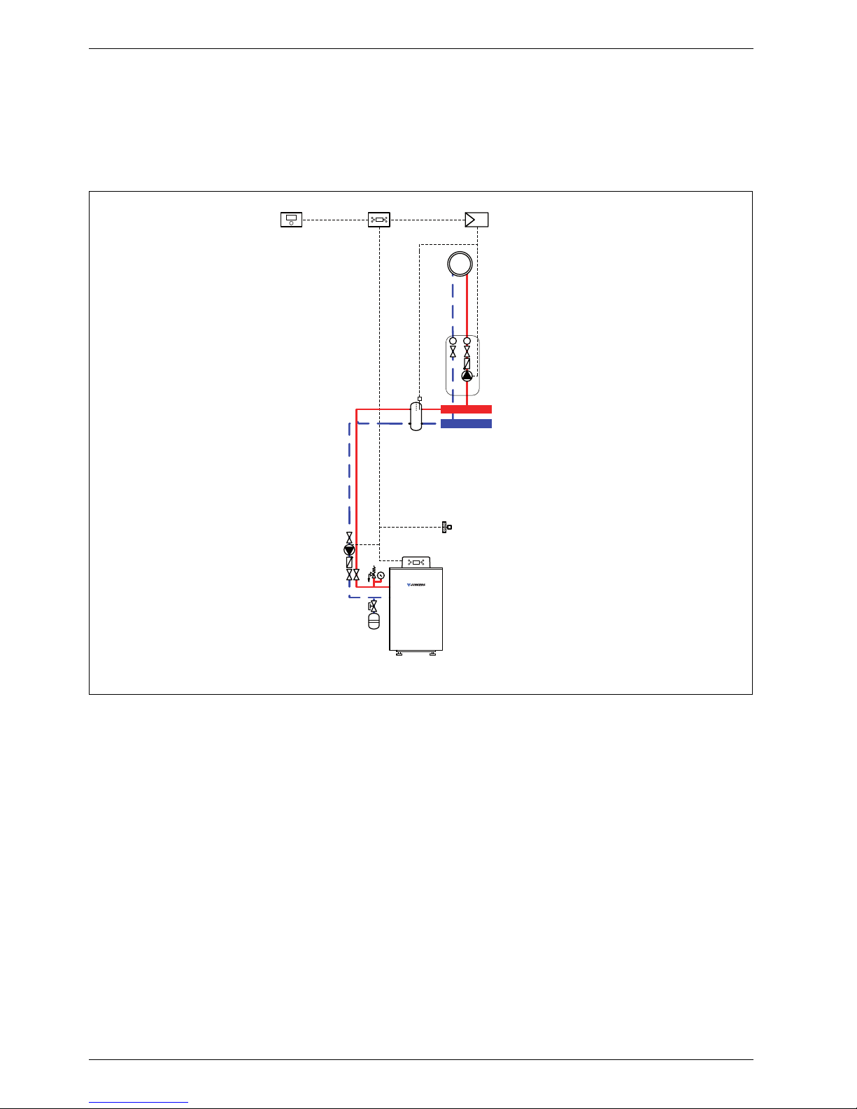
1.1 System scheme 1: unmixed heating circuit, low loss header
Hydraulic scheme with controller (schematic diagram)
Fig. 1
AF Outside temperature sensor
CUx Boiler control unit
FW 100 Weather-compensated controller
HP Heating circuit pump (primary circuit)
IPM 1 Load switching module for one heating circuit
P Heating circuit pump (secondary circuit)
VF Common flow temperature sensor
1 Module position: on the heat source
3 Module position: on the wall
Heating system components
• Suprapur gas condensing boiler for balanced flue
operation
• One unmixed heating circuit
• Weather-compensated controller
Features
• Generally, we would recommend the installation of a
low loss header on site to ensure reliable transfer of
the required heating output.
• The FW ... weather-compensated controller is
preferred for its higher utilisation of condensing
technology.
• Determine the system water content and select a
corresponding expansion vessel (Æ page 39).
Function description
The unmixed heating circuit with low loss header is
regulated by an FW 100 weather-compensated
controller. This always requires the IPM 1 load switching
module. A 2-wire BUS system enables communication
between the boiler control unit, the controller and the
load switching module.
6 720 643 417-02.1O
IPM 1
AF
FW 100
3
CUx
1
VF
T
T
P
3
Suprapur
KBR 120-280
HP
Page 5
System schemes
6 720 645 817 (2010/09)
5
The controller is suitable for wall mounting inside the
boiler room or in the living space. Installing it in the living
space enables room temperature hook-up.
Parts list
Model code Description Part no. Pce Price
Condensing boiler
KBR 120-3 A 23 Suprapur gas condensing boiler for natural gas 23 8 718 577 229
KBR 120-3 A 21 Suprapur gas condensing boiler for natural gas 21 8 718 577 285
KBR 160-3 A 23 Suprapur gas condensing boiler for natural gas 23 8 718 577 230
KBR 160-3 A 21 Suprapur gas condensing boiler for natural gas 21 8 718 577 286
KBR 200-3 A 23 Suprapur gas condensing boiler for natural gas 23 8 718 577 231
KBR 200-3 A 21 Suprapur gas condensing boiler for natural gas 21 8 718 577 287
KBR 240-3 A 23 Suprapur gas condensing boiler for natural gas 23 8 718 577 232
KBR 240-3 A 21 Suprapur gas condensing boiler for natural gas 21 8 718 577 288
KBR 280-3 A 23 Suprapur gas condensing boiler for natural gas 23 8 718 577 233
KBR 280-3 A 21 Suprapur gas condensing boiler for natural gas 21 8 718 577 289
Connection accessories
Boiler safety assembly for KBR 120-3 A 7 747 003 386
Boiler safety assembly for KBR 160 ... 280-3 A 7 747 003 387
Shut-off gate valve set for KBR 120-3 A 7 747 301 389
Shut-off gate valve set for KBR 160 ... 280-3 A 7 747 301 390
Dirt trap with fine sieve, DN 50, PN 6 80 950 210
Dirt trap with fine sieve, DN 65, PN 6 80 950 212
Dirt trap with standard sieve, DN 50, PN 6 80 950 110
Dirt trap with standard sieve, DN 65, PN 6 80 950 112
Gas tap R ¾ with TAE, for KBR 120-3 A 7 747 201 234
Gas tap R 1 ¼ with TAE, for KBR 160 ... 280-3 A 7 747 201 236
Compensator for gas connection, DN 25, for KBR 120-3 A 7 747 200 920
Compensator for gas connection, DN 32,
for KBR 160 ... 280-3 A
7 747 200 921
MAG ... (Æ page 72)
Controllers
FW 100 Weather-compensated controller 7 719 002 923
Controller accessories
FB 100 Remote control 7 719 002 907
IPM 1 Load switching module for one heating circuit 7 719 002 738
Other accessories
No. 1620 Condensate pump 80 695 080
No. 1605 Neutralising tank incl. neutralising granulate 8 718 576 749
No. 1606 Neutralising tank incl. condensate pump and neutralising
granulate
8 718 577 421
No. 1607 Neutralising granulate 7 115 120
Flue accessories (incl. boiler flue connection with test port)
(Æ chapter 11 from page 75)
Tab. 1
Page 6
System schemes
6 720 645 817 (2010/09)
6
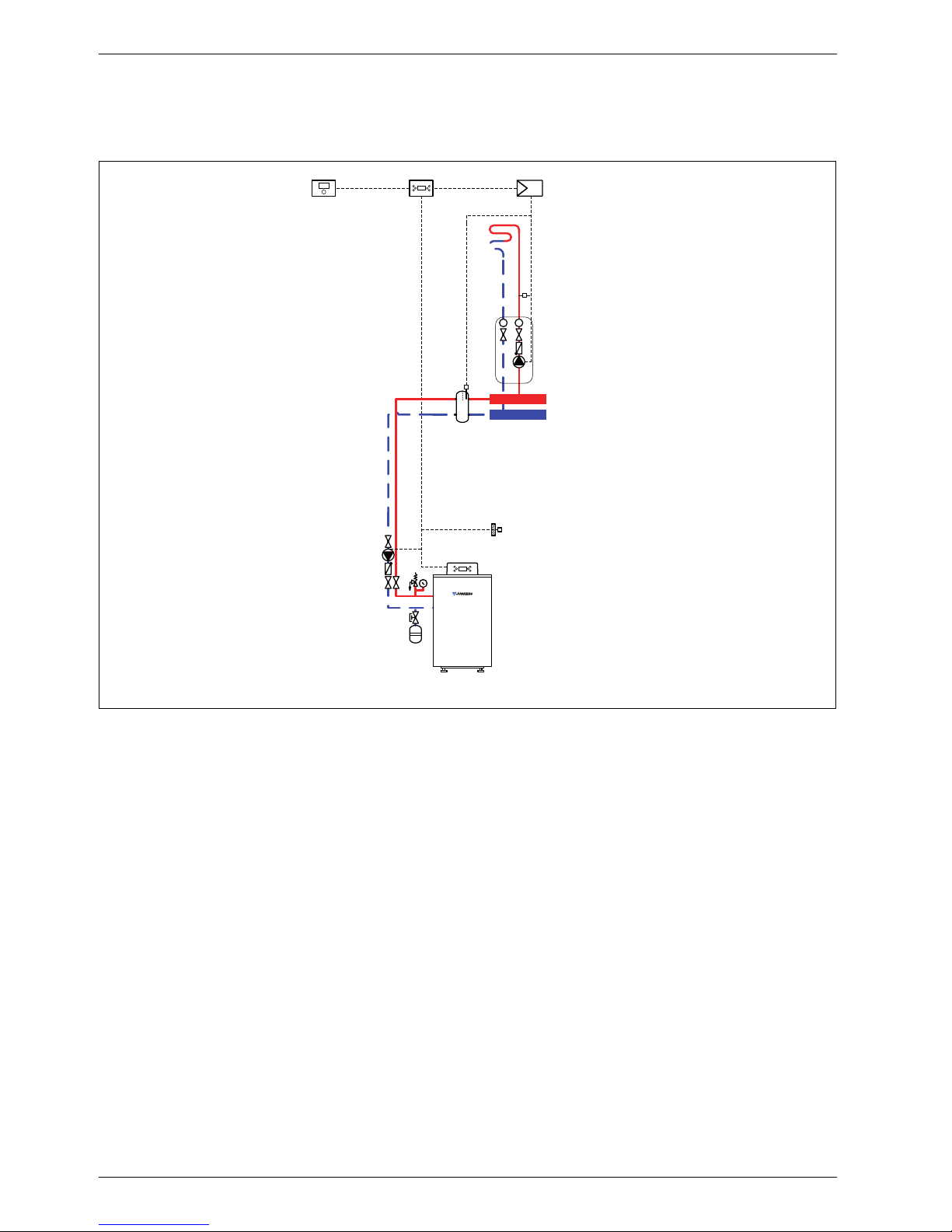
1.2 System scheme 2: unmixed underfloor heating circuit, low loss header
Hydraulic scheme with controller (schematic diagram)
Fig. 2
AF Outside temperature sensor
CUx Boiler control unit
FW 100 Weather-compensated controller
HP Heating circuit pump (primary circuit)
IPM 1 Load switching module for one heating circuit
P Heating circuit pump (secondary circuit)
TB Temperature limiter
VF Common flow temperature sensor
1 Module position: on the heat source
3 Module position: on the wall
Heating system components
• Suprapur gas condensing boiler for balanced flue
operation, without diaphragm expansion vessel
• One unmixed underfloor heating circuit
• Weather-compensated controller
Features
• Generally, we would recommend the installation of a
low loss header on site to ensure reliable transfer of
the required heating output.
• The FW ... weather-compensated controller is
preferred for its higher utilisation of condensing
technology.
• Determine the system water content and select a
corresponding expansion vessel (Æ page 39).
• Install a mechanical safety limiter (TB 1) in
accordance with the underfloor heating system
manufacturer's instructions.
Function description
The unmixed underfloor heating circuit with low loss
header is regulated by one FW 100 weathercompensated controller. This always requires the IPM 1
load switching module. A 2-wire BUS system enables
communication between the boiler control unit, the
controller and the load switching module.
The controller is suitable for wall mounting inside the
boiler room or in the living space. Installing it in the living
space enables room temperature hook-up.
1 MPI001 WF
3
AF
T
T
P
TB
CUx
1
VF
Suprapur
KBR 120-280
HP
3
6 720 643 417-01.1O
Page 7

System schemes
6 720 645 817 (2010/09)
7
Parts list
Model code Description Part no. Pce Price
Condensing boiler
KBR 120-3 A 23 Suprapur gas condensing boiler for natural gas 23 8 718 577 229
KBR 120-3 A 21 Suprapur gas condensing boiler for natural gas 21 8 718 577 285
KBR 160-3 A 23 Suprapur gas condensing boiler for natural gas 23 8 718 577 230
KBR 160-3 A 21 Suprapur gas condensing boiler for natural gas 21 8 718 577 286
KBR 200-3 A 23 Suprapur gas condensing boiler for natural gas 23 8 718 577 231
KBR 200-3 A 21 Suprapur gas condensing boiler for natural gas 21 8 718 577 287
KBR 240-3 A 23 Suprapur gas condensing boiler for natural gas 23 8 718 577 232
KBR 240-3 A 21 Suprapur gas condensing boiler for natural gas 21 8 718 577 288
KBR 280-3 A 23 Suprapur gas condensing boiler for natural gas 23 8 718 577 233
KBR 280-3 A 21 Suprapur gas condensing boiler for natural gas 21 8 718 577 289
Connection accessories
Boiler safety assembly for KBR 120-3 A 7 747 003 386
Boiler safety assembly for KBR 160 ... 280-3 A 7 747 003 387
Shut-off gate valve set for KBR 120-3 A 7 747 301 389
Shut-off gate valve set for KBR 160 ... 280-3 A 7 747 301 390
Dirt trap with fine sieve, DN 50, PN 6 80 950 210
Dirt trap with fine sieve, DN 65, PN 6 80 950 212
Dirt trap with standard sieve, DN 50, PN 6 80 950 110
Dirt trap with standard sieve, DN 65, PN 6 80 950 112
Gas tap R ¾ with TAE, for KBR 120-3 A 7 747 201 234
Gas tap R 1 ¼ with TAE, for KBR 160 ... 280-3 A 7 747 201 236
Compensator for gas connection, DN 25, for KBR 120-3 A 7 747 200 920
Compensator for gas connection, DN 32,
for KBR 160 ... 280-3 A
7 747 200 921
MAG ... (Æ page 72)
Controllers
FW 100 Weather-compensated controller 7 719 002 923
Controller accessories
FB 100 Remote control 7 719 002 907
IPM 1 Load switching module for one heating circuit 7 719 002 738
TB 1 Temperature limiter 7 719 002 255
Other accessories
No. 1620 Condensate pump 80 695 080
No. 1605 Neutralising tank incl. neutralising granulate 8 718 576 749
No. 1606 Neutralising tank incl. condensate pump and neutralising
granulate
8 718 577 421
No. 1607 Neutralising granulate 7 115 120
Flue accessories (incl. boiler flue connection with test port)
(Æ chapter 11 from page 75)
Tab. 2
Page 8
System schemes
6 720 645 817 (2010/09)
8
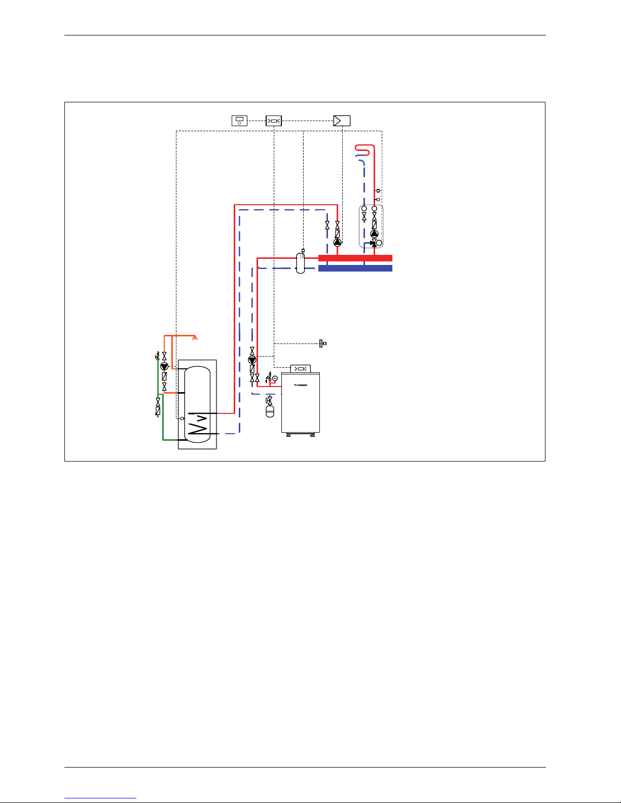
1.3 System scheme 3: mixed heating circuit, DHW circuit, low loss header
Hydraulic scheme with controller (schematic diagram)
Fig. 3
AF Outside temperature sensor
CUx Boiler control unit
FW 100 Weather-compensated controller
HP Heating circuit pump (primary circuit)
IPM 2 Load switching module for two heating circuits
LP Cylinder primary pump
M 3-way mixer
MF Mixer circuit temperature sensor
P Heating circuit pump (secondary circuit)
SF Cylinder temperature sensor
ST DHW cylinder
TB Temperature limiter
VF Common flow temperature sensor
ZP DHW circulation pump
1 Module position: on the heat source
3 Module position: on the wall
Heating system components
• Suprapur gas condensing boiler for balanced flue
operation
• One mixed heating circuit
• DHW cylinder
• Weather-compensated controller
Features
• Generally, we would recommend the installation of a
low loss header on site to ensure reliable transfer of
the required heating output.
• The FW ... weather-compensated controller is
preferred for its higher utilisation of condensing
technology.
• Determine the system water content and select a
corresponding expansion vessel (Æ page 39).
• Install a mechanical safety limiter (TB 1) in
accordance with the underfloor heating system
manufacturer's instructions.
• Install safety assembly to DIN 1988.
Function description
The mixed heating circuit with low loss header and
DHW heating are regulated by an FW 100 weathercompensated controller. This always requires the IPM 2
load switching module. A 2-wire BUS system enables
communication between the boiler control unit, the
controller and the load switching module.
6 720 643 417-03.1O
3
AF
3
CUx 2 MPI001 W
F
T
T
M
M
P
MF
TB
VF
LP
1
ZP
SF
ST ...
Suprapur
KBR 120-280
HP
Page 9

System schemes
6 720 645 817 (2010/09)
9
The controller is suitable for wall mounting inside the
boiler room or in the living space. Installing it in the living
space enables room temperature hook-up.
Parts list
Model code Description Part no. Pce Price
Condensing boiler
KBR 120-3 A 23 Suprapur gas condensing boiler for natural gas 23 8 718 577 229
KBR 120-3 A 21 Suprapur gas condensing boiler for natural gas 21 8 718 577 285
KBR 160-3 A 23 Suprapur gas condensing boiler for natural gas 23 8 718 577 230
KBR 160-3 A 21 Suprapur gas condensing boiler for natural gas 21 8 718 577 286
KBR 200-3 A 23 Suprapur gas condensing boiler for natural gas 23 8 718 577 231
KBR 200-3 A 21 Suprapur gas condensing boiler for natural gas 21 8 718 577 287
KBR 240-3 A 23 Suprapur gas condensing boiler for natural gas 23 8 718 577 232
KBR 240-3 A 21 Suprapur gas condensing boiler for natural gas 21 8 718 577 288
KBR 280-3 A 23 Suprapur gas condensing boiler for natural gas 23 8 718 577 233
KBR 280-3 A 21 Suprapur gas condensing boiler for natural gas 21 8 718 577 289
Connection accessories
Boiler safety assembly for KBR 120-3 A 7 747 003 386
Boiler safety assembly for KBR 160 ... 280-3 A 7 747 003 387
Shut-off gate valve set for KBR 120-3 A 7 747 301 389
Shut-off gate valve set for KBR 160 ... 280-3 A 7 747 301 390
Dirt trap with fine sieve, DN 50, PN 6 80 950 210
Dirt trap with fine sieve, DN 65, PN 6 80 950 212
Dirt trap with standard sieve, DN 50, PN 6 80 950 110
Dirt trap with standard sieve, DN 65, PN 6 80 950 112
Gas tap R ¾ with TAE, for KBR 120-3 A 7 747 201 234
Gas tap R 1 ¼ with TAE, for KBR 160 ... 280-3 A 7 747 201 236
Compensator for gas connection, DN 25, for KBR 120-3 A 7 747 200 920
Compensator for gas connection, DN 32,
for KBR 160 ... 280-3 A
7 747 200 921
MAG ... (Æ page 72)
DHW cylinder
(Æ chapter 9 from page 60)
Controllers
FW 100 Weather-compensated controller 7 719 002 923
Controller accessories
FB 100 Remote control 7 719 002 907
IPM 2 Load switching module for two heating circuits 7 719 002 739
TB 1 Temperature limiter 7 719 002 255
Other accessories
No. 1620 Condensate pump 80 695 080
No. 1605 Neutralising tank incl. neutralising granulate 8 718 576 749
No. 1606 Neutralising tank incl. condensate pump and neutralising
granulate
8 718 577 421
No. 1607 Neutralising granulate 7 115 120
Flue accessories (incl. boiler flue connection with test port)
(Æ chapter 11 from page 75)
Tab. 3
Page 10
System schemes
6 720 645 817 (2010/09)
10
1.4 System scheme 4: one unmixed heating circuit, one mixed heating circuit, low loss
header
Hydraulic scheme with controller (schematic diagram)
Fig. 4
AF Outside temperature sensor
CUx Boiler control unit
FW 200 Weather-compensated controller
HP Heating circuit pump (primary circuit)
IPM 2 Load switching module for two heating circuits
M 3-way mixer
MF Mixer circuit temperature sensor
P
1,2
Heating circuit pump (secondary circuit)
TB Temperature limiter
VF Common flow temperature sensor
1 Module position: on the heat source
3 Module position: on the wall
Heating system components
• Suprapur gas condensing boiler for balanced flue
operation, without diaphragm expansion vessel
• One unmixed heating circuit
• One mixed heating circuit
• Weather-compensated controller
Features
• Generally, we would recommend the installation of a
low loss header on site to ensure reliable transfer of
the required heating output.
• The FW ... weather-compensated controller is
preferred for its higher utilisation of condensing
technology.
• Determine the system water content and select a
corresponding expansion vessel (Æ page 39).
• Install a mechanical safety limiter (TB 1) in
accordance with the underfloor heating system
manufacturer's instructions.
Function description
The heating circuits are regulated by an FW 200
weather-compensated controller. This always requires
the IPM 2 load switching module. A 2-wire BUS system
enables communication between the boiler control unit,
the controller and the load switching module.
6 720 643 417-04.1O
1
AF
3
T
T
P1
T
T
M
M
P2
MF
TB
IPM 2
CUx
FW 200
3
VF
Suprapur
KBR 120-280
HP
Page 11

System schemes
6 720 645 817 (2010/09)
11
The controller is suitable for wall mounting inside the
boiler room or in the living space. Installing it in the living
space enables room temperature hook-up.
Parts list
Model code Description Part no. Pce Price
Condensing boiler
KBR 120-3 A 23 Suprapur gas condensing boiler for natural gas 23 8 718 577 229
KBR 120-3 A 21 Suprapur gas condensing boiler for natural gas 21 8 718 577 285
KBR 160-3 A 23 Suprapur gas condensing boiler for natural gas 23 8 718 577 230
KBR 160-3 A 21 Suprapur gas condensing boiler for natural gas 21 8 718 577 286
KBR 200-3 A 23 Suprapur gas condensing boiler for natural gas 23 8 718 577 231
KBR 200-3 A 21 Suprapur gas condensing boiler for natural gas 21 8 718 577 287
KBR 240-3 A 23 Suprapur gas condensing boiler for natural gas 23 8 718 577 232
KBR 240-3 A 21 Suprapur gas condensing boiler for natural gas 21 8 718 577 288
KBR 280-3 A 23 Suprapur gas condensing boiler for natural gas 23 8 718 577 233
KBR 280-3 A 21 Suprapur gas condensing boiler for natural gas 21 8 718 577 289
Connection accessories
Boiler safety assembly for KBR 120-3 A 7 747 003 386
Boiler safety assembly for KBR 160 ... 280-3 A 7 747 003 387
Shut-off gate valve set for KBR 120-3 A 7 747 301 389
Shut-off gate valve set for KBR 160 ... 280-3 A 7 747 301 390
Dirt trap with fine sieve, DN 50, PN 6 80 950 210
Dirt trap with fine sieve, DN 65, PN 6 80 950 212
Dirt trap with standard sieve, DN 50, PN 6 80 950 110
Dirt trap with standard sieve, DN 65, PN 6 80 950 112
Gas tap R ¾ with TAE, for KBR 120-3 A 7 747 201 234
Gas tap R 1 ¼ with TAE, for KBR 160 ... 280-3 A 7 747 201 236
Compensator for gas connection, DN 25, for KBR 120-3 A 7 747 200 920
Compensator for gas connection, DN 32,
for KBR 160 ... 280-3 A
7 747 200 921
MAG ... (Æ page 72)
Controllers
FW 200 Weather-compensated controller 7 719 002 507
Controller accessories
FB 100 Remote control 7 719 002 907
IPM 2 Load switching module for two heating circuits 7 719 002 739
TB 1 Temperature limiter 7 719 002 255
Other accessories
No. 1620 Condensate pump 80 695 080
No. 1605 Neutralising tank incl. neutralising granulate 8 718 576 749
No. 1606 Neutralising tank incl. condensate pump and neutralising
granulate
8 718 577 421
No. 1607 Neutralising granulate 7 115 120
Flue accessories (incl. boiler flue connection with test port)
(Æ chapter 11 from page 75)
Tab. 4
Page 12
System schemes
6 720 645 817 (2010/09)
12
1.5 System scheme 5: two mixed heating circuits, one DHW circuit, low loss header
Hydraulic scheme with controller (schematic diagram)
Fig. 5
AF Outside temperature sensor
CUx Boiler control unit
FW 200 Weather-compensated controller
HP Heating circuit pump (primary circuit)
IPM 1 Load switching module for one heating circuit
IPM 2 Load switching module for two heating circuits
LP Cylinder primary pump
M
1,2
3-way mixer
MF
1,2
Mixer circuit temperature sensor
P
1,2
Heating circuit pump (secondary circuit)
SF Cylinder temperature sensor
ST ... DHW cylinder
TB
1,2
Temperature limiter
VF Common flow temperature sensor
ZP DHW circulation pump
1 Module position: on the heat source
3 Module position: on the wall
Heating system components
• Suprapur gas condensing boiler for balanced flue
operation
• Two mixed heating circuits
• DHW cylinder
• Weather-compensated controller
Features
• Generally, we would recommend the installation of a
low loss header on site to ensure reliable transfer of
the required heating output.
• The FW ... weather-compensated controller is
preferred for its higher utilisation of condensing
technology.
• Determine the system water content and select a
corresponding expansion vessel (Æ page 39).
• Install a mechanical safety limiter (TB 1) in
accordance with the underfloor heating system
manufacturer's instructions.
• Install safety assembly to DIN 1988.
Function description
The heating circuits are regulated by an FW 200
weather-compensated controller. This always requires
the IPM 1 and IPM 2 load switching modules. A 2-wire
BUS system enables communication between the boiler
control unit, the controller and the load switching
modules.
6 720 643 417-06.1O
AF
T
T
M
M2
P2
MF2
TB2
LP
VF
1
3
IPM 1
CUx
FW 200
3
3
IPM 2
ZP
SF
ST ...
Suprapur
KBR 120-280
HP
T
T
M
M1
P1
MF1
TB1
Page 13

System schemes
6 720 645 817 (2010/09)
13
The controller is suitable for wall mounting inside the
boiler room or in the living space. Installing it in the living
space enables room temperature hook-up.
Parts list
Model code Description Part no. Pce Price
Condensing boiler
KBR 120-3 A 23 Suprapur gas condensing boiler for natural gas 23 8 718 577 229
KBR 120-3 A 21 Suprapur gas condensing boiler for natural gas 21 8 718 577 285
KBR 160-3 A 23 Suprapur gas condensing boiler for natural gas 23 8 718 577 230
KBR 160-3 A 21 Suprapur gas condensing boiler for natural gas 21 8 718 577 286
KBR 200-3 A 23 Suprapur gas condensing boiler for natural gas 23 8 718 577 231
KBR 200-3 A 21 Suprapur gas condensing boiler for natural gas 21 8 718 577 287
KBR 240-3 A 23 Suprapur gas condensing boiler for natural gas 23 8 718 577 232
KBR 240-3 A 21 Suprapur gas condensing boiler for natural gas 21 8 718 577 288
KBR 280-3 A 23 Suprapur gas condensing boiler for natural gas 23 8 718 577 233
KBR 280-3 A 21 Suprapur gas condensing boiler for natural gas 21 8 718 577 289
Connection accessories
Boiler safety assembly for KBR 120-3 A 7 747 003 386
Boiler safety assembly for KBR 160 ... 280-3 A 7 747 003 387
Shut-off gate valve set for KBR 120-3 A 7 747 301 389
Shut-off gate valve set for KBR 160 ... 280-3 A 7 747 301 390
Dirt trap with fine sieve, DN 50, PN 6 80 950 210
Dirt trap with fine sieve, DN 65, PN 6 80 950 212
Dirt trap with standard sieve, DN 50, PN 6 80 950 110
Dirt trap with standard sieve, DN 65, PN 6 80 950 112
Gas tap R ¾ with TAE, for KBR 120-3 A 7 747 201 234
Gas tap R 1 ¼ with TAE, for KBR 160 ... 280-3 A 7 747 201 236
Compensator for gas connection, DN 25, for KBR 120-3 A 7 747 200 920
Compensator for gas connection, DN 32,
for KBR 160 ... 280-3 A
7 747 200 921
MAG ... (Æ page 72)
DHW cylinder
(Æ chapter 9 from page 60)
Controllers
FW 200 Weather-compensated controller 7 719 002 507
Controller accessories
FB 100 Remote control 7 719 002 907
IPM 1 Load switching module for one heating circuit 7 719 002 738
IPM 2 Load switching module for two heating circuits 7 719 002 739
TB 1 Temperature limiter 7 719 002 255
Other accessories
No. 1620 Condensate pump 80 695 080
No. 1605 Neutralising tank incl. neutralising granulate 8 718 576 749
No. 1606 Neutralising tank incl. condensate pump and neutralising
granulate
8 718 577 421
No. 1607 Neutralising granulate 7 115 120
Flue accessories (incl. boiler flue connection with test port)
(Æ chapter 11 from page 75)
Tab. 5
Page 14
System schemes
6 720 645 817 (2010/09)
14
1.6 System scheme 6: one unmixed heating circuit, two mixed heating circuits, low loss
header
Hydraulic scheme with controller (schematic diagram)
Fig. 6
AF Outside temperature sensor
CUx Boiler control unit
FB 100 Remote control
FW 200 Weather-compensated controller
HP Heating circuit pump (primary circuit)
IPM 1 Load switching module for one heating circuit
IPM 2 Load switching module for two heating circuits
M
2,3
3-way mixer
MF
2,3
Mixer circuit temperature sensor
P
1,3
Heating circuit pump (secondary circuit)
TB Temperature limiter
VF Common flow temperature sensor
1 Module position: on the heat source
3 Module position: on the wall
Heating system components
• Suprapur gas condensing boiler for balanced flue
operation
• One unmixed heating circuit
• Two mixed heating circuits
• Weather-compensated controller
Features
• Generally, we would recommend the installation of a
low loss header on site to ensure reliable transfer of
the required heating output.
• The FW ... weather-compensated controller is
preferred for its higher utilisation of condensing
technology.
• Determine the system water content and select a
corresponding expansion vessel (Æ page 39).
• Install a mechanical safety limiter (TB 1) in
accordance with the underfloor heating system
manufacturer's instructions.
• Install safety assembly to DIN 1988.
Function description
The heating circuits are regulated by an FW 200
weather-compensated controller. This always requires
the IPM 1 and IPM 2 load switching modules. A 2-wire
BUS system enables communication between the boiler
control unit, the controller and the load switching
modules.
6 720 643 417-07.1O
IPM 2 IPM 1AFFB 100
VK
T
T
P1
T
T
M
M2
P2
MF2
TB
T
T
M
M3
P3
MF3
TB
1
CUx
FW 200
3
333
Suprapur
KBR 120-280
HP
Page 15

System schemes
6 720 645 817 (2010/09)
15
The controller is suitable for wall mounting inside the
boiler room or in the living space. Installing it in the living
space enables room temperature hook-up.
A FB 100 remote control is required for the third heating
circuit.
Parts list
Model code Description Part no. Pce Price
Condensing boiler
KBR 120-3 A 23 Suprapur gas condensing boiler for natural gas 23 8 718 577 229
KBR 120-3 A 21 Suprapur gas condensing boiler for natural gas 21 8 718 577 285
KBR 160-3 A 23 Suprapur gas condensing boiler for natural gas 23 8 718 577 230
KBR 160-3 A 21 Suprapur gas condensing boiler for natural gas 21 8 718 577 286
KBR 200-3 A 23 Suprapur gas condensing boiler for natural gas 23 8 718 577 231
KBR 200-3 A 21 Suprapur gas condensing boiler for natural gas 21 8 718 577 287
KBR 240-3 A 23 Suprapur gas condensing boiler for natural gas 23 8 718 577 232
KBR 240-3 A 21 Suprapur gas condensing boiler for natural gas 21 8 718 577 288
KBR 280-3 A 23 Suprapur gas condensing boiler for natural gas 23 8 718 577 233
KBR 280-3 A 21 Suprapur gas condensing boiler for natural gas 21 8 718 577 289
Connection accessories
Boiler safety assembly for KBR 120-3 A 7 747 003 386
Boiler safety assembly for KBR 160 ... 280-3 A 7 747 003 387
Shut-off gate valve set for KBR 120-3 A 7 747 301 389
Shut-off gate valve set for KBR 160 ... 280-3 A 7 747 301 390
Dirt trap with fine sieve, DN 50, PN 6 80 950 210
Dirt trap with fine sieve, DN 65, PN 6 80 950 212
Dirt trap with standard sieve, DN 50, PN 6 80 950 110
Dirt trap with standard sieve, DN 65, PN 6 80 950 112
Gas tap R ¾ with TAE, for KBR 120-3 A 7 747 201 234
Gas tap R 1 ¼ with TAE, for KBR 160 ... 280-3 A 7 747 201 236
Compensator for gas connection, DN 25, for KBR 120-3 A 7 747 200 920
Compensator for gas connection, DN 32,
for KBR 160 ... 280-3 A
7 747 200 921
MAG ... (Æ page 72)
Controllers
FW 200 Weather-compensated controller 7 719 002 507
Controller accessories
FB 100 Remote control 7 719 002 907
IPM 1 Load switching module for one heating circuit 7 719 002 738
IPM 2 Load switching module for two heating circuits 7 719 002 739
TB 1 Temperature limiter 7 719 002 255
Other accessories
No. 1620 Condensate pump 80 695 080
No. 1605 Neutralising tank incl. neutralising granulate 8 718 576 749
No. 1606 Neutralising tank incl. condensate pump and neutralising
granulate
8 718 577 421
No. 1607 Neutralising granulate 7 115 120
Flue accessories (incl. boiler flue connection with test port)
(Æ chapter 11 from page 75)
Tab. 6
Page 16
System schemes
6 720 645 817 (2010/09)
16
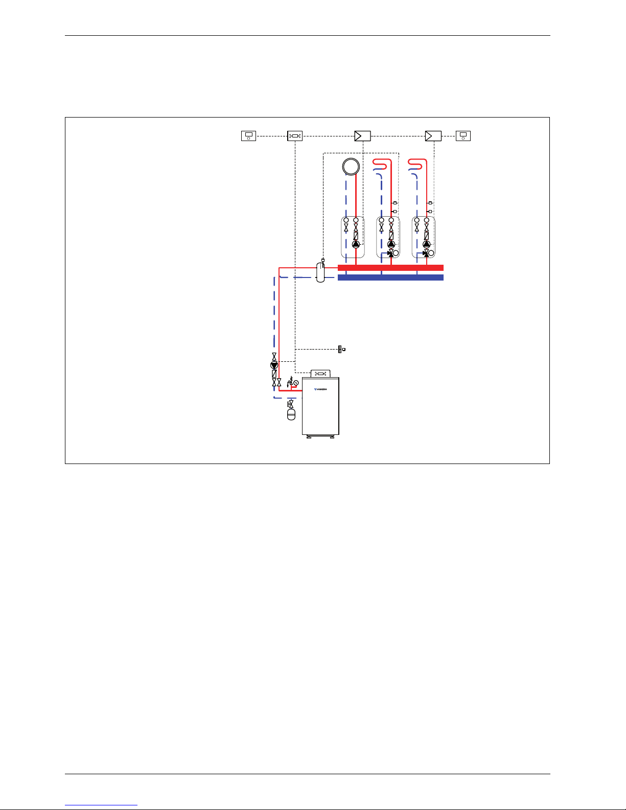
1.7 System scheme 7: one unmixed heating circuit, three mixed heating circuits, low loss
header
Hydraulic scheme with controller (schematic diagram)
Fig. 7
AF Outside temperature sensor
CUx Boiler control unit
FB 100 Remote control
FW 200 Weather-compensated controller
HP Heating circuit pump (primary circuit)
IPM 2 Load switching module for two heating circuits
M
2,4
3-way mixer
MF
2,4
Mixer circuit temperature sensor
P
1,4
Heating circuit pump (secondary circuit)
TB Temperature limiter
VF Common flow temperature sensor
1 Module position: on the heat source
3 Module position: on the wall
Heating system components
• Suprapur gas condensing boiler for balanced flue
operation, without diaphragm expansion vessel
• One unmixed heating circuit
• Three mixed heating circuits
• Weather-compensated controller
Features
• Generally, we would recommend the installation of a
low loss header on site to ensure reliable transfer of
the required heating output.
• The FW ... weather-compensated controller is
preferred for its higher utilisation of condensing
technology.
• Determine the system water content and select a
corresponding expansion vessel (Æ page 39).
• Install a mechanical safety limiter (TB 1) in
accordance with the underfloor heating system
manufacturer's instructions.
Function description
The heating circuits are regulated by an FW 200
weather-compensated controller. This always requires
two IPM 2 load switching modules. A 2-wire BUS system
enables communication between the boiler control unit,
the controller and the load switching modules.
6 720 643 417-08.1O
IPM 2 IPM 2
AF
FB 100 FB 100
1
CUx
FW 200
333
3
3
VF
T
T
P1
T
T
M
M2
P2
MF2
TB
T
T
M
M3
P3
MF3
TB
T
T
M
M4
P4
MF4
TB
Suprapur
KBR 120-280
HP
Page 17
System schemes
6 720 645 817 (2010/09)
17
The controller is suitable for wall mounting inside the
boiler room or in the living space. Installing it in the living
space enables room temperature hook-up.
One FB 100 remote control is required for each of the
third and fourth heating circuits.
Parts list
Model code Description Part no. Pce Price
Condensing boiler
KBR 120-3 A 23 Suprapur gas condensing boiler for natural gas 23 8 718 577 229
KBR 120-3 A 21 Suprapur gas condensing boiler for natural gas 21 8 718 577 285
KBR 160-3 A 23 Suprapur gas condensing boiler for natural gas 23 8 718 577 230
KBR 160-3 A 21 Suprapur gas condensing boiler for natural gas 21 8 718 577 286
KBR 200-3 A 23 Suprapur gas condensing boiler for natural gas 23 8 718 577 231
KBR 200-3 A 21 Suprapur gas condensing boiler for natural gas 21 8 718 577 287
KBR 240-3 A 23 Suprapur gas condensing boiler for natural gas 23 8 718 577 232
KBR 240-3 A 21 Suprapur gas condensing boiler for natural gas 21 8 718 577 288
KBR 280-3 A 23 Suprapur gas condensing boiler for natural gas 23 8 718 577 233
KBR 280-3 A 21 Suprapur gas condensing boiler for natural gas 21 8 718 577 289
Connection accessories
Boiler safety assembly for KBR 120-3 A 7 747 003 386
Boiler safety assembly for KBR 160 ... 280-3 A 7 747 003 387
Shut-off gate valve set for KBR 120-3 A 7 747 301 389
Shut-off gate valve set for KBR 160 ... 280-3 A 7 747 301 390
Dirt trap with fine sieve, DN 50, PN 6 80 950 210
Dirt trap with fine sieve, DN 65, PN 6 80 950 212
Dirt trap with standard sieve, DN 50, PN 6 80 950 110
Dirt trap with standard sieve, DN 65, PN 6 80 950 112
Gas tap R ¾ with TAE, for KBR 120-3 A 7 747 201 234
Gas tap R 1 ¼ with TAE, for KBR 160 ... 280-3 A 7 747 201 236
Compensator for gas connection, DN 25, for KBR 120-3 A 7 747 200 920
Compensator for gas connection, DN 32,
for KBR 160 ... 280-3 A
7 747 200 921
MAG ... (Æ page 72)
Controllers
FW 200 Weather-compensated controller 7 719 002 507
Controller accessories
FB 100 Remote control 7 719 002 907
IPM 2 Load switching module for two heating circuits 7 719 002 739
TB 1 Temperature limiter 7 719 002 255
Other accessories
No. 1620 Condensate pump 80 695 080
No. 1605 Neutralising tank incl. neutralising granulate 8 718 576 749
No. 1606 Neutralising tank incl. condensate pump and neutralising
granulate
8 718 577 421
No. 1607 Neutralising granulate 7 115 120
Flue accessories (incl. boiler flue connection with test port)
(Æ chapter 11 from page 75)
Tab. 7
Page 18
System schemes
6 720 645 817 (2010/09)
18
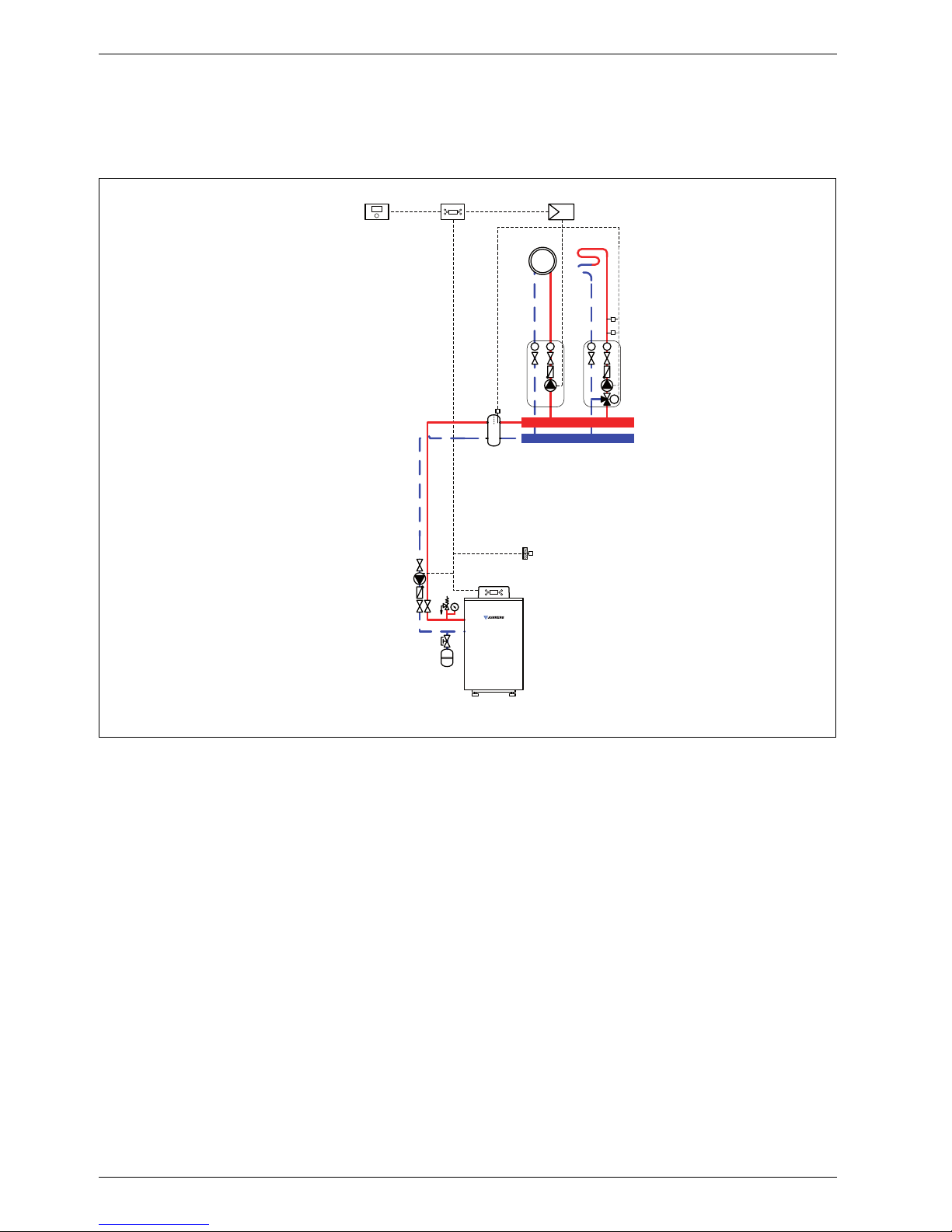
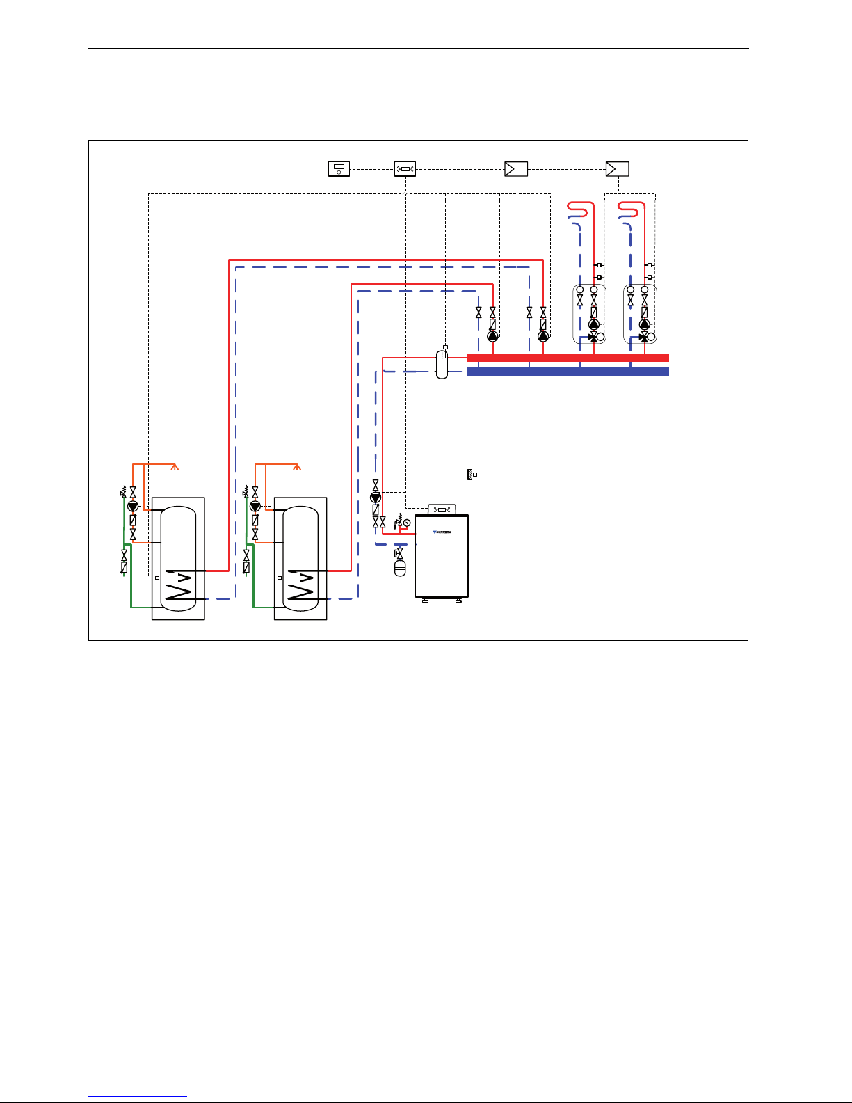
1.8 System scheme 8: two mixed heating circuits, two DHW circuits, low loss header
Hydraulic scheme with controller (schematic diagram)
Fig. 8
AF Outside temperature sensor
CUx Boiler control unit
FW 500 Weather-compensated controller
HP Heating circuit pump (primary circuit)
IPM 2 Load switching module for two heating circuits
LP
1,2
Cylinder primary pump
M
1,2
3-way mixer
MF
1,2
Mixer circuit temperature sensor
P
1,2
Heating circuit pump (secondary circuit)
SF Cylinder temperature sensor
ST ... DHW cylinder
TB Temperature limiter
VF Common flow temperature sensor
ZP DHW circulation pump
1 Module position: on the heat source
3 Module position: on the wall
Heating system components
• Suprapur gas condensing boiler for balanced flue
operation
• Two mixed heating circuits
• Two DHW circuits
• Weather-compensated controller
Features
• Generally, we would recommend the installation of a
low loss header on site to ensure reliable transfer of
the required heating output.
• The FW ... weather-compensated controller is
preferred for its higher utilisation of condensing
technology.
• Determine the system water content and select a
corresponding expansion vessel (Æ page 39).
• Install a mechanical safety limiter (TB 1) in
accordance with the underfloor heating system
manufacturer's instructions.
• Install safety assembly to DIN 1988.
6 720 643 417-09.1O
IPM 2
AF
LP1 LP2
TT
M
M1
P1
MF1
TB
TT
M
M2
P2
MF2
TB
IPM 2
3
3
VF
1
CUx
FW 500
3
Suprapur
KBR 120-280
HP
ZP
SF
ST ...
ZP
SF
ST ...
Page 19

System schemes
6 720 645 817 (2010/09)
19
Function description
The heating circuits are regulated by an FW 500
weather-compensated controller. This always requires
two IPM 2 load switching modules. A 2-wire BUS system
enables communication between the boiler control unit,
the controller and the load switching modules.
The controller is suitable for wall mounting inside the
boiler room or in the living space. Installing it in the living
space enables room temperature hook-up.
Parts list
Model code Description Part no. Pce Price
Condensing boiler
KBR 120-3 A 23 Suprapur gas condensing boiler for natural gas 23 8 718 577 229
KBR 120-3 A 21 Suprapur gas condensing boiler for natural gas 21 8 718 577 285
KBR 160-3 A 23 Suprapur gas condensing boiler for natural gas 23 8 718 577 230
KBR 160-3 A 21 Suprapur gas condensing boiler for natural gas 21 8 718 577 286
KBR 200-3 A 23 Suprapur gas condensing boiler for natural gas 23 8 718 577 231
KBR 200-3 A 21 Suprapur gas condensing boiler for natural gas 21 8 718 577 287
KBR 240-3 A 23 Suprapur gas condensing boiler for natural gas 23 8 718 577 232
KBR 240-3 A 21 Suprapur gas condensing boiler for natural gas 21 8 718 577 288
KBR 280-3 A 23 Suprapur gas condensing boiler for natural gas 23 8 718 577 233
KBR 280-3 A 21 Suprapur gas condensing boiler for natural gas 21 8 718 577 289
Connection accessories
Boiler safety assembly for KBR 120-3 A 7 747 003 386
Boiler safety assembly for KBR 160 ... 280-3 A 7 747 003 387
Shut-off gate valve set for KBR 120-3 A 7 747 301 389
Shut-off gate valve set for KBR 160 ... 280-3 A 7 747 301 390
Dirt trap with fine sieve, DN 50, PN 6 80 950 210
Dirt trap with fine sieve, DN 65, PN 6 80 950 212
Dirt trap with standard sieve, DN 50, PN 6 80 950 110
Dirt trap with standard sieve, DN 65, PN 6 80 950 112
Gas tap R ¾ with TAE, for KBR 120-3 A 7 747 201 234
Gas tap R 1 ¼ with TAE, for KBR 160 ... 280-3 A 7 747 201 236
Compensator for gas connection, DN 25, for KBR 120-3 A 7 747 200 920
Compensator for gas connection, DN 32,
for KBR 160 ... 280-3 A
7 747 200 921
MAG ... (Æ page 72)
DHW cylinder
(Æ chapter 9 from page 60)
Controllers
FW 500 Weather-compensated controller 7 719 002 966
Controller accessories
FB 100 Remote control 7 719 002 907
IPM 2 Load switching module for two heating circuits 7 719 002 739
TB 1 Temperature limiter 7 719 002 255
Other accessories
No. 1620 Condensate pump 80 695 080
No. 1605 Neutralising tank incl. neutralising granulate 8 718 576 749
No. 1606 Neutralising tank incl. condensate pump and neutralising
granulate
8 718 577 421
No. 1607 Neutralising granulate 7 115 120
Flue accessories (incl. boiler flue connection with test port)
(Æ chapter 11 from page 75)
Tab. 8
Page 20
System schemes
6 720 645 817 (2010/09)
20
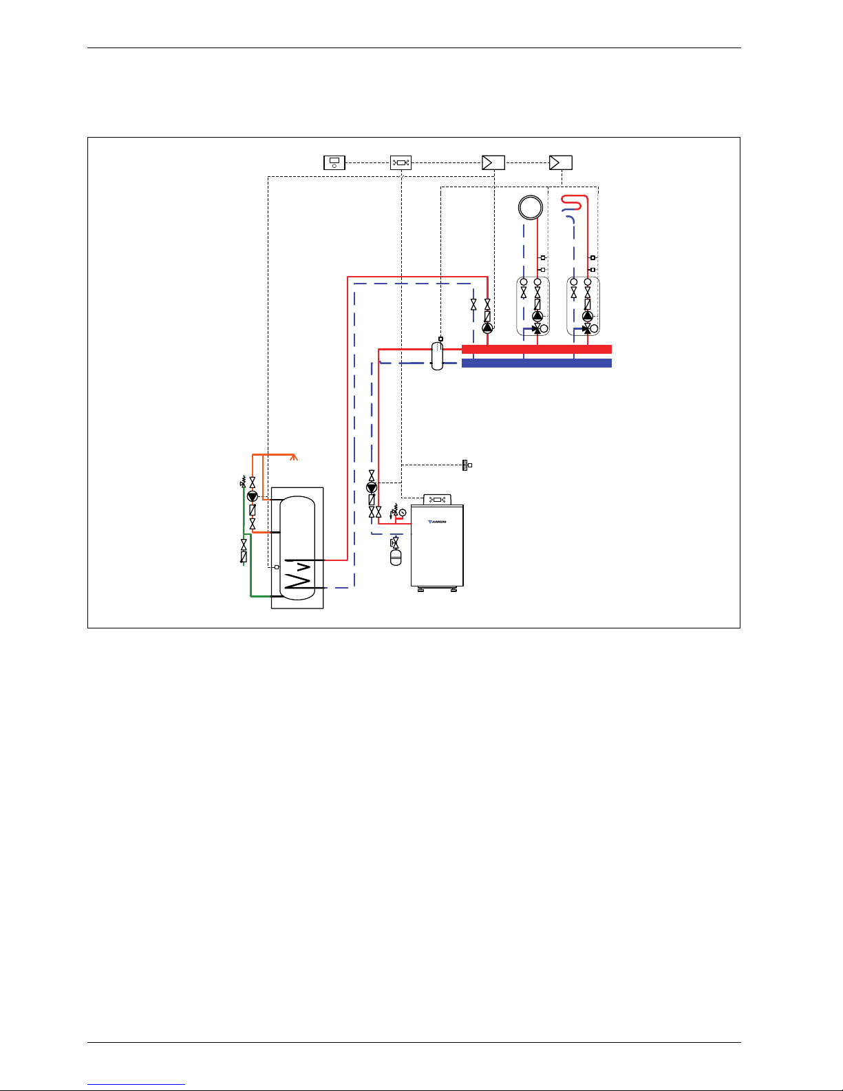
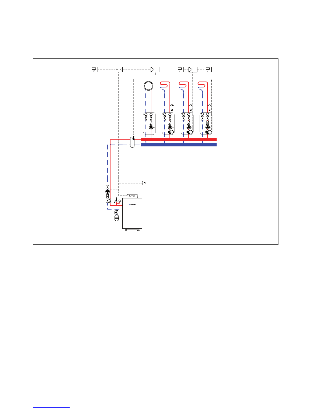
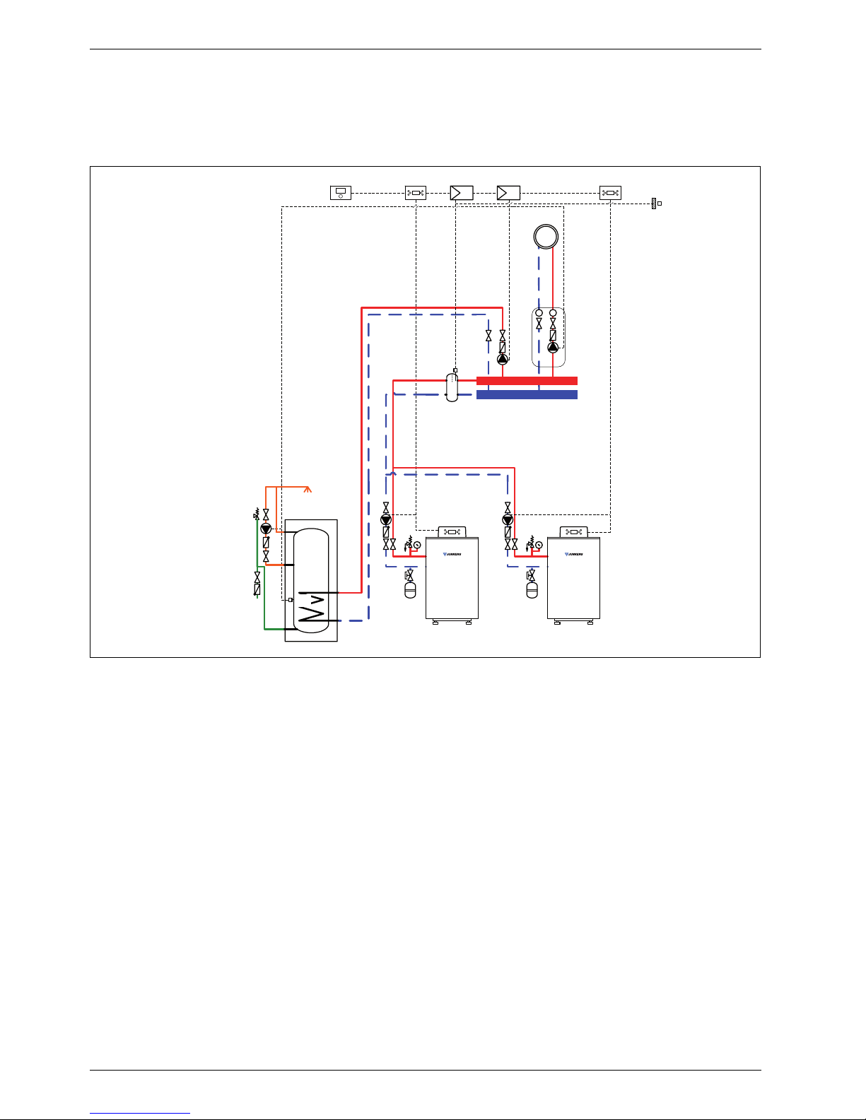
1.9 System scheme 9: one unmixed heating circuit, one DHW circuit, low loss header,
cascade
Hydraulic scheme with controller (schematic diagram)
Fig. 9
AF Outside temperature sensor
CUx Boiler control unit
FW 200 Weather-compensated controller
HP Heating circuit pump (primary circuit)
ICM Cascade switching module
IPM 2 Load switching module for two heating circuits
LP Cylinder primary pump
P Heating circuit pump (secondary circuit)
SF Cylinder temperature sensor
ST ... DHW cylinder
VF Common flow temperature sensor
ZP DHW circulation pump
1 Module position: on the heat source
3 Module position: on the wall
Heating system components
• Two Suprapur gas condensing boilers for balanced
flue operation
• One unmixed heating circuit
• One DHW circuit
• Weather-compensated controller
• Cascade switching module
Features
• The on-site installation of a low loss header is
required to ensure the reliable transfer of the
required heating output.
• The FW ... weather-compensated controller is
preferred for its higher utilisation of condensing
technology.
• Determine the system water content and select a
corresponding expansion vessel (Æ page 39).
• Install safety assembly to DIN 1988.
Function description
The boiler cascade, the unmixed heating circuit and the
DHW circuit are regulated by an FW 200 weathercompensated controller. This always requires two IPM 2
load switching modules. A 2-wire BUS system enables
communication between the boiler control units, the
controller and the load switching modules.
6 720 643 417-10.1O
3
IPM 2
AF
3
FW 200 ICM
3
CUx
1
ZP
SF
ST ...
LP
VF
TT
P
HP
Suprapur
MKB 240-560
HP
CUx
1
Page 21
System schemes
6 720 645 817 (2010/09)
21
The controller is suitable for wall mounting inside the
boiler room or in the living space. Installing it in the living
space enables room temperature hook-up.
Parts list
Model code Description Part no. Pce Price
Condensing boiler
KBR 120-3 A 23 Suprapur gas condensing boiler for natural gas 23 8 718 577 229
KBR 120-3 A 21 Suprapur gas condensing boiler for natural gas 21 8 718 577 285
KBR 160-3 A 23 Suprapur gas condensing boiler for natural gas 23 8 718 577 230
KBR 160-3 A 21 Suprapur gas condensing boiler for natural gas 21 8 718 577 286
KBR 200-3 A 23 Suprapur gas condensing boiler for natural gas 23 8 718 577 231
KBR 200-3 A 21 Suprapur gas condensing boiler for natural gas 21 8 718 577 287
KBR 240-3 A 23 Suprapur gas condensing boiler for natural gas 23 8 718 577 232
KBR 240-3 A 21 Suprapur gas condensing boiler for natural gas 21 8 718 577 288
KBR 280-3 A 23 Suprapur gas condensing boiler for natural gas 23 8 718 577 233
KBR 280-3 A 21 Suprapur gas condensing boiler for natural gas 21 8 718 577 289
Connection accessories
Boiler safety assembly for KBR 120-3 A 7 747 003 386
Boiler safety assembly for KBR 160 ... 280-3 A 7 747 003 387
Shut-off gate valve set for KBR 120-3 A 7 747 301 389
Shut-off gate valve set for KBR 160 ... 280-3 A 7 747 301 390
Dirt trap with fine sieve, DN 50, PN 6 80 950 210
Dirt trap with fine sieve, DN 65, PN 6 80 950 212
Dirt trap with standard sieve, DN 50, PN 6 80 950 110
Dirt trap with standard sieve, DN 65, PN 6 80 950 112
Gas tap R ¾ with TAE, for KBR 120-3 A 7 747 201 234
Gas tap R 1 ¼ with TAE, for KBR 160 ... 280-3 A 7 747 201 236
Compensator for gas connection, DN 25, for KBR 120-3 A 7 747 200 920
Compensator for gas connection, DN 32,
for KBR 160 ... 280-3 A
7 747 200 921
MAG ... (Æ page 72)
DHW cylinder
(Æ chapter 9 from page 60)
Controllers
FW 200 Weather-compensated controller 7 719 002 507
ICM Cascade switching module 7 719 002 949
Controller accessories
FB 100 Remote control 7 719 002 907
IPM 2 Load switching module for two heating circuits 7 719 002 739
TB 1 Temperature limiter 7 719 002 255
Other accessories
No. 1620 Condensate pump 80 695 080
No. 1605 Neutralising tank incl. neutralising granulate 8 718 576 749
No. 1606 Neutralising tank incl. condensate pump and neutralising
granulate
8 718 577 421
No. 1607 Neutralising granulate 7 115 120
Flue accessories (incl. boiler flue connection with test port)
(Æ chapter 11 from page 75)
Tab. 9
Page 22
Specification
6 720 645 817 (2010/09)
22
2 Specification
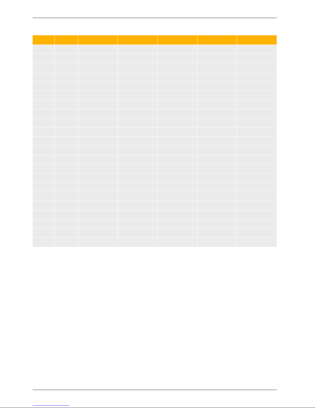
2.1 Appliance parameters
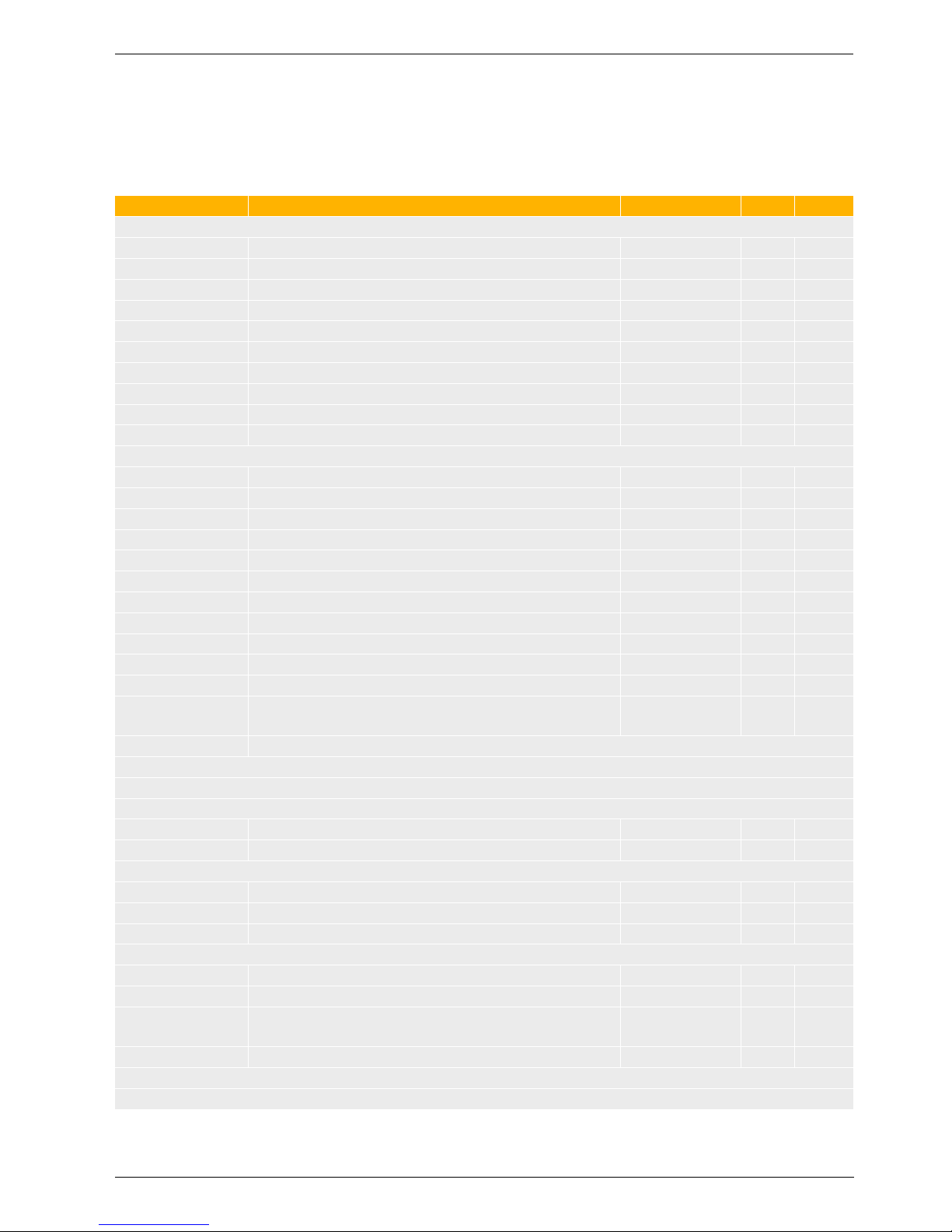
2.1.1 Single appliance Suprapur KBR ...
Boiler size (output in kW) Unit KBR 120-3 A KBR 160-3 A KBR 200-3 A KBR 200-3 A KBR 240-3 A
Number of sections – 4 5 6 7 8
Rated output full load/partial load
temperature pair 50/30 °C
kW 120/31 160/42 200/62 240/75 280/87
Rated output full load/partial load
temperature pair 80/60 °C
kW 113/28 150/38 187/56.2 225/67.6 263/79.2
Rated heat input full load/partial load kW 115.9/29 155/38.8 193/57.9 232/69.6 271/81.3
Flue gas mass flow rate full load/partial
load temperature pair 50/30 °C
g/s 53.8/10.1 70.2/12.9 87.8/21.5 106.0/23.0 125.9/28.4
Flue gas mass flow rate full load/partial
load temperature pair 80/60 °C
g/s 53.7/11.1 70.2/14.1 89.3/21.6 107.4/25.0 125.4/33.4
CO2 content with natural gas full load/
partial load
% 9.1/9.3
Minimum flue gas temperature full load/
partial load temperature pair 50/30 °C
°C 56/32 54/31 55/34 55/33 57/34
Minimum flue gas temperature full load/
partial load temperature pair 80/60 °C
°C < 75/57 < 75/56 < 75/59 < 75/58 < 75/59
Available draught, flue system Pa 100
Type (acc. to DVGW regulations) –
B23, B
23P
, C53, (C63), C
93
open flue and balanced flue operation
Gas
Fan – G1G 170
Gas valve –
Honeywell Kromschröder
VR 4615V VR 415VE CG 20 CG 25 CG 25
Gas restrictor diameter:
Natural gas H (G20),
Wobbe index 14.9 kWh/m
3
Natural gas L (Germany),
Wobbe index 12.8 kWh/m
3
mm
mm
15.7
15.0
Gas
restrictor
not fitted
14.2
14.2
13.6
13.6
12.6
12.6
Heating water circuit
Boiler water capacity l 16 20 24 27 30
Pressure drop on heating water side mbar Æ Fig. 14, page 29
Maximum flow temperature °C 85
Safety temp. for high limit safety cut-out °C 100
Permissible operating pressure bar 4
Electrical data
IP rating – IPX0D
Power supply V/Hz 230/50
Power consumption full load/partial load W 150/40 190/45 230/50 270/50 330/50
Appliance dimensions and weight
Handling dimensions
Width × Depth × Height
mm
851 × 612
× 1400
1059 × 612
× 1400
1059 × 612
×1400
1267 × 612
× 1400
1267 × 612
× 1400
Weight kg 205 240 265 300 330
Tab. 10 Specification
Page 23
Specification
6 720 645 817 (2010/09)
23
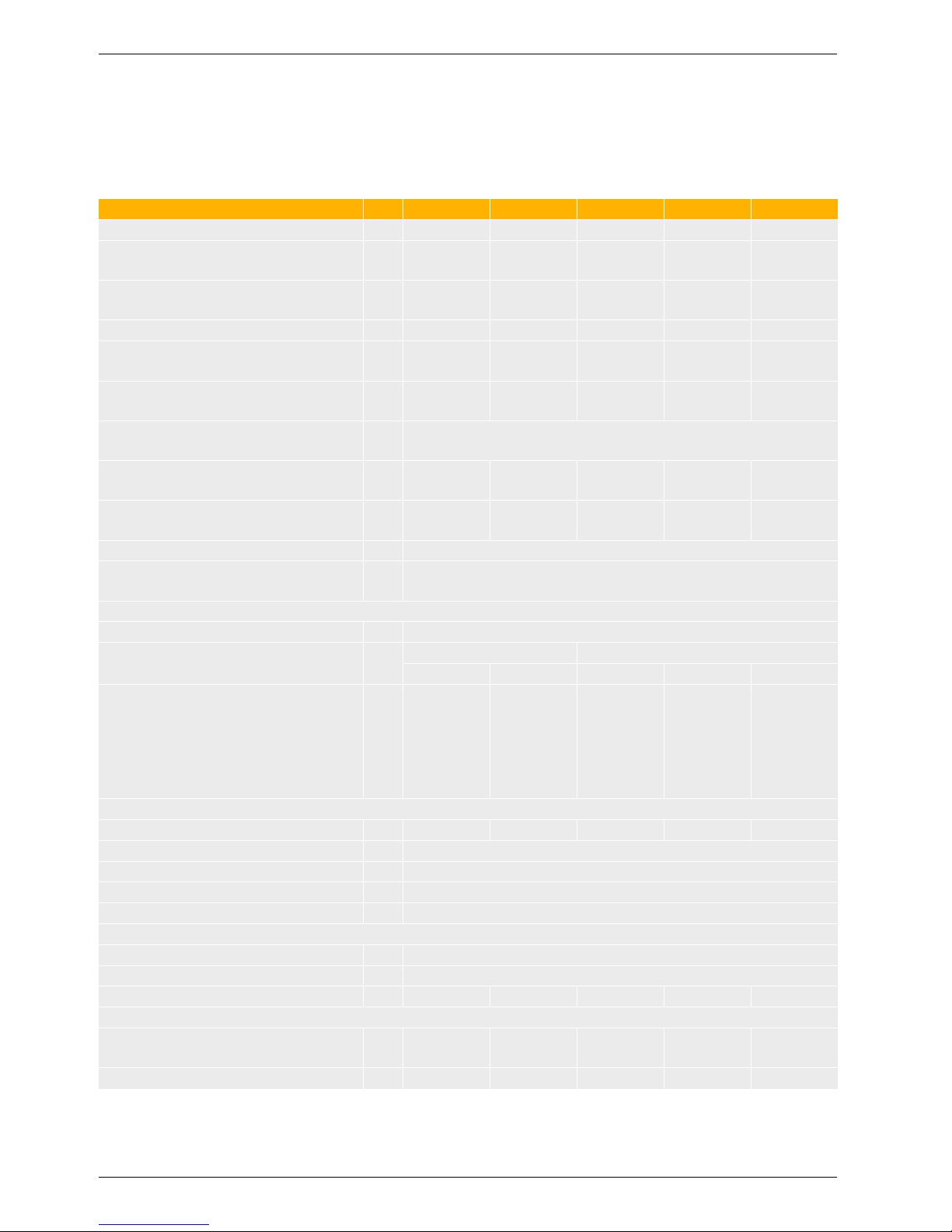
2.1.2 Factory-prepared cascade Suprapur MKB ...
Boiler size (output in kW) Unit
MKB
240-3 A
MKB
320-3 A
MKB
400-3 A
MKB
480-3 A
MKB
560-3 A
Number of sections – 8 10 12 14 16
Rated output full load/partial load
temperature pair 50/30 °C
kW 240/31 320/42 400/62 480/75 560/87
Rated output full load/partial load
temperature pair 80/60 °C
kW 226/28 300/38 374/56.2 450/67.6 526/79.2
Rated heat input full load/partial load kW 232/29 310/38.8 386/57.9 464/69.6 542/81.3
Flue gas mass flow rate full load/partial
load temperature pair 50/30 °C
g/s 53.8/10.1 70.2/12.9 87.8/21.5 106.0/23.0 125.9/28.4
Flue gas mass flow rate full load/partial
load temperature pair 80/60 °C
g/s 53.7/11.1 70.2/14.1 89.3/21.6 107.4/25.0 125.4/33.4
CO2 content with natural gas full load/
partial load
% 9.1/9.3
Minimum flue gas temperature full load/
partial load temperature pair 50/30 °C
°C 56/32 54/31 55/34 55/33 57/34
Minimum flue gas temperature full load/
partial load temperature pair 80/60 °C
°C < 75/57 < 75/56 < 75/59 < 75/58 < 75/59
Available draught, flue system Pa 100
Type (acc. to DVGW regulations) –
B23, B
23P
, C53, (C63), C
93
open flue and balanced flue operation
Gas
Fan – G1G 170
Gas valve –
Honeywell Kromschröder
VR 4615V VR 415VE CG 20 CG 25 CG 25
Gas restrictor diameter:
Natural gas H (G20),
Wobbe index 14.9 kWh/m
3
Natural gas L (Germany),
Wobbe index 12.8 kWh/m
3
mm
mm
15.7
15.0
Gas
restrictor
not fitted
14.2
14.2
13.6
13.6
12.6
12.6
Heating water circuit
Boiler water capacity l 32 40 48 54 60
Pressure drop on heating water side mbar Æ Fig. 15, page 29
Maximum flow temperature °C 85
Safety temp. for high limit safety cut-out °C 100
Permissible operating pressure bar 4
Electrical data
IP rating – IP X0D
Power supply V/Hz 230/50
Power consumption full load/partial load W 300/40 380/45 460/50 540/50 660/50
Appliance dimensions and weight
Handling dimensions
Width × Depth × Height
mm
851 × 612
× 1400
1059 × 612
× 1400
1059 × 612
× 1400
1267 × 612
× 1400
1267 × 612
× 1400
Weight kg 410 480 530 600 660
Tab. 11 Specification
Page 24
Specification
6 720 645 817 (2010/09)
24
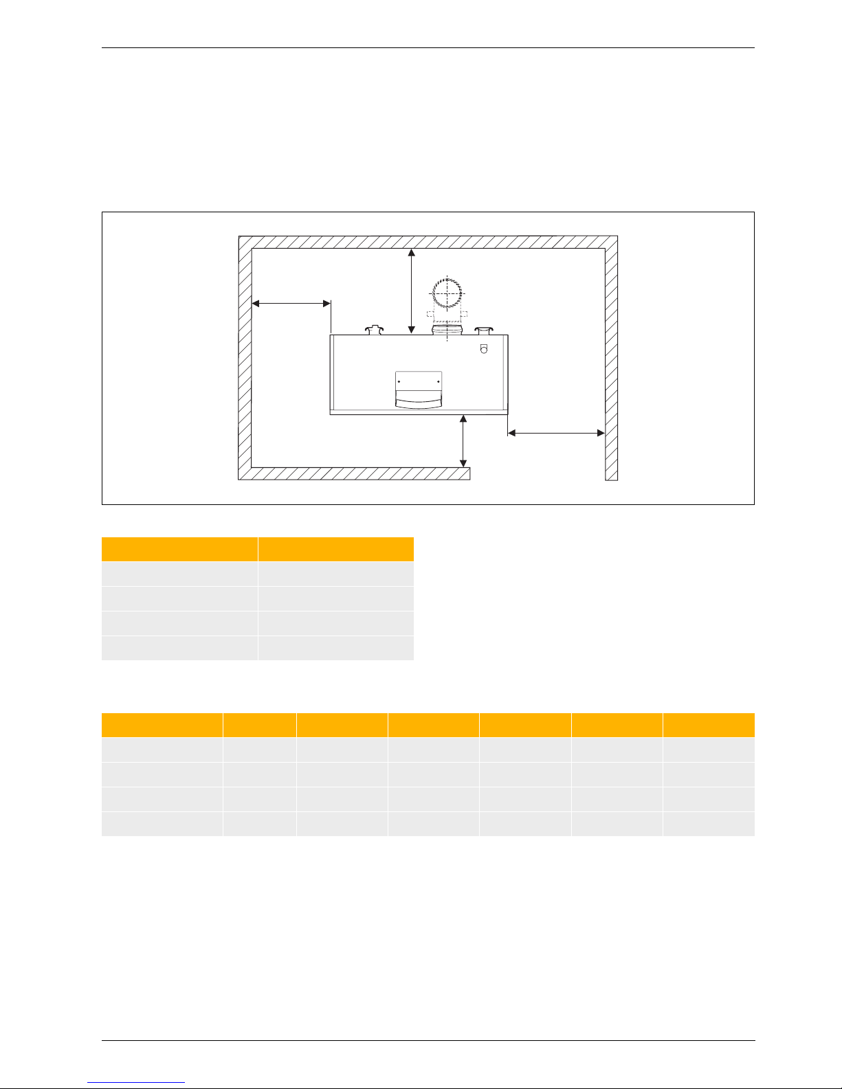
2.2 Dimensions and minimum clearances
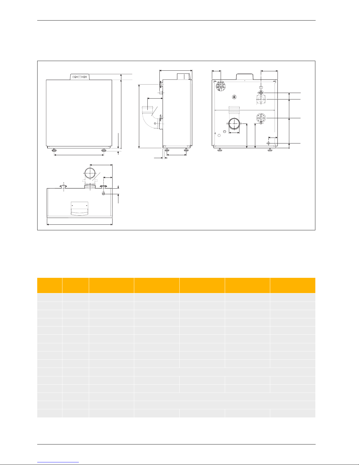
2.2.1 Single appliance Suprapur KBR ...
Fig. 10 Suprapur KBR 120 ... 280-3 A
AA Flue gas connection
AKO Condensate outlet
AL Combustion air pipe connection
(balanced flue operation only)
GAS Gas connection
MAG Connection for diaphragm expansion vessel
RK Boiler return
SV Safety valve or safety assembly connection
VK Boiler flow
1) Not part of the standard boiler delivery
1143
1018
615
100
X
GAS
, XAL, X
RK
Z
AA
X
AA
Y
AA
Y
VK
Y
MAG
Ø
AA
GAS
AL
RK
AA
SV
VK
MAG
6 720 643 417-24.1O
AKO
182
176
176
1515
1400
1)
1)
680
496
F
B
34
15 - 25
120
Unit
KBR 120-3 A
MKB 240-3 A
KBR 160-3 A
MKB 320-3 A
KBR 200-3 A
MKB 400-3 A
KBR 240-3 A
MKB 480-3 A
KBR 280-3 A
MKB 560-3 A
B mm 916 1124 1124 1332 1332
Ø
AA
DN 160 160 200 200 200
X
AA
mm 293 345 397 449 501
Y
AA
mm 470 470 495 495 495
Z
AA
mm 145 145 310 310 310
F mm 800 1008 1008 1216 1216
Y
MAG
mm 522 514 514 514 514
Ø
AL
DN 110 110 110 110 110
X
AL
mm 231 335 231 335 231
VK, RK – Rp 2 (DN 50) PN 6 standard flange (DN 65)
X
RK
mm 231 335 231 335 231
Y
VK
mm 1308 1300 1300 1300 1300
SV – R 1 R 1¼
ØGAS – R ¾ R 1½
X
GAS
mm 231 335 231 335 231
Tab. 12 Measurements and connection dimensions
Page 25

Specification
6 720 645 817 (2010/09)
25
2.2.2 Factory-prepared 2-boiler cascade MKB ...
Fig. 11 Factory-prepared 2-boiler cascade
AA Flue gas connection
AL Combustion air pipe connection (balanced flue operation only)
GAS Gas connection
RK Boiler return
VK Boiler flow
1) Pump installation point, boiler circuit
6 720 643 417-13.1O
717
1)
T
G
T
Z
615
114 3
1018
Y
AA
Ø
AA
1)
Y
RK
Y
VK
215
500
OM
B
G
B
K
S
N
K
X
AA
X
GAS, XAL
AL
GAS
VK
RK
U
1517
R
1)
Page 26
Specification
6 720 645 817 (2010/09)
26
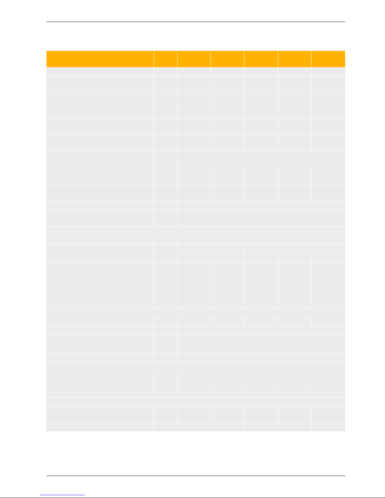
Unit MKB 240-3 A MKB 320-3 A MKB 400-3 A MKB 480-3 A MKB 560-3 A
B
K
mm 994 1202 1202 1410 1410
B
G
mm 2041 2243 2421 2620 2573
T
G
mm 1842 1995 2135 2139 2135
T
Z
mm 640 795 935 939 935
ØAA – DN 200 DN 200 DN 250 DN 250 DN 250
Y
AA
mm 1335 1342 2126 2135 2130
X
AA
mm 332 384 436 488 540
ØVK – DN 65 DN 80 DN 80 DN 100 DN 100
Y
VK
mm 1308 1299 1299 1299 1299
ØRK – DN 65 DN 80 DN 80 DN 100 DN 100
Y
RK
mm 339.5 330 330 330 330
ØGAS inch R¾ R1¼ R1¼ R1¼ R1¼
X
GAS
mm 270 374 270 374 270
ØAL – DN 100 DN 100 DN 100 DN 100 DN 100
X
AL
mm 270 374 270 374 270
K mm 327 433 327 431 327
M mm 455 453 663 663 871
N mm 270 375 270 369 270
O mm 518 563 567 619 619
R mm 565 775 773 982 981
S mm 419 367 515 454 407
U mm 226 263 259 259 259
Tab. 13 Dimensions Suprapur – factory-prepared 2-boiler cascade
Page 27
Specification
6 720 645 817 (2010/09)
27
2.3 Installed dimensions
Wherever possible, site the Suprapur gas condensing
boiler with the recommended wall clearances
(Æ Fig. 12). This ensures good accessibility for
installation, maintenance and service.
A reduction of the minimum clearances makes boiler
access more difficult.
2.3.1 Single appliance Suprapur KBR ...
Fig. 12 Installed dimensions Suprapur single boiler
Minimum handling details
A
C
B
D
6 720 644 748-07.1O
Dimension Wall clearance in mm
A 700/500
B 700/550
C 500/100
D 700/500
Tab. 14 Recommended/minimum wall clearances
Unit KBR 120-3 A KBR 160-3 A KBR 200-3 A KBR 240-3 A KBR 280-3 A
Minimum depth mm 612 612 612 612 612
Minimum width mm 855 1065 1065 1275 1275
Minimum height mm 1405 1405 1405 1405 1405
Minimum weight kg 190 219 244 277 307
Tab. 15 Minimum handling details Suprapur single boiler
Page 28

Specification
6 720 645 817 (2010/09)
28
2.3.2 Factory-prepared cascade MKB ...
Fig. 13 Installed dimensions Suprapur factory-prepared 2-boiler cascade (dim. in mm)
Minimum handling details
Unit MKB 240-3 A MKB 320-3 A MKB 400-3 A MKB 480-3 A MKB 560-3 A
A mm 700/500 700/500 700/500 700/500 700/500
B mm –/900 –/850 –/1000 –/940 –/890
C
1)
1) If the cascade pipework is installed in a different direction, then C = A
mm –/1320 –/1370 –/1370 –/1420 –/1420
S mm –/419 –/367 –/515 –/454 –/407
Tab. 16 Recommended/minimum installed dimensions Suprapur – factory-prepared 2-boiler cascade
A
B
≥ 100
S
C
800
A
6 720 644 748-09.1O
Installation example: The pipework for flue
gas and heating water can be turned 180°.
Unit MKB 240-3 A MKB 320-3 A MKB 400-3 A MKB 480-3 A MKB 560-3 A
Minimum depth mm 612 612 612 612 612
Minimum width mm 855 1065 1065 1275 1275
Minimum height mm 1405 1405 1405 1405 1405
Minimum weight kg 190 219 244 277 307
Tab. 17 Minimum handling details Suprapur factory-prepared 2-boiler cascade
Page 29
Specification
6 720 645 817 (2010/09)
29
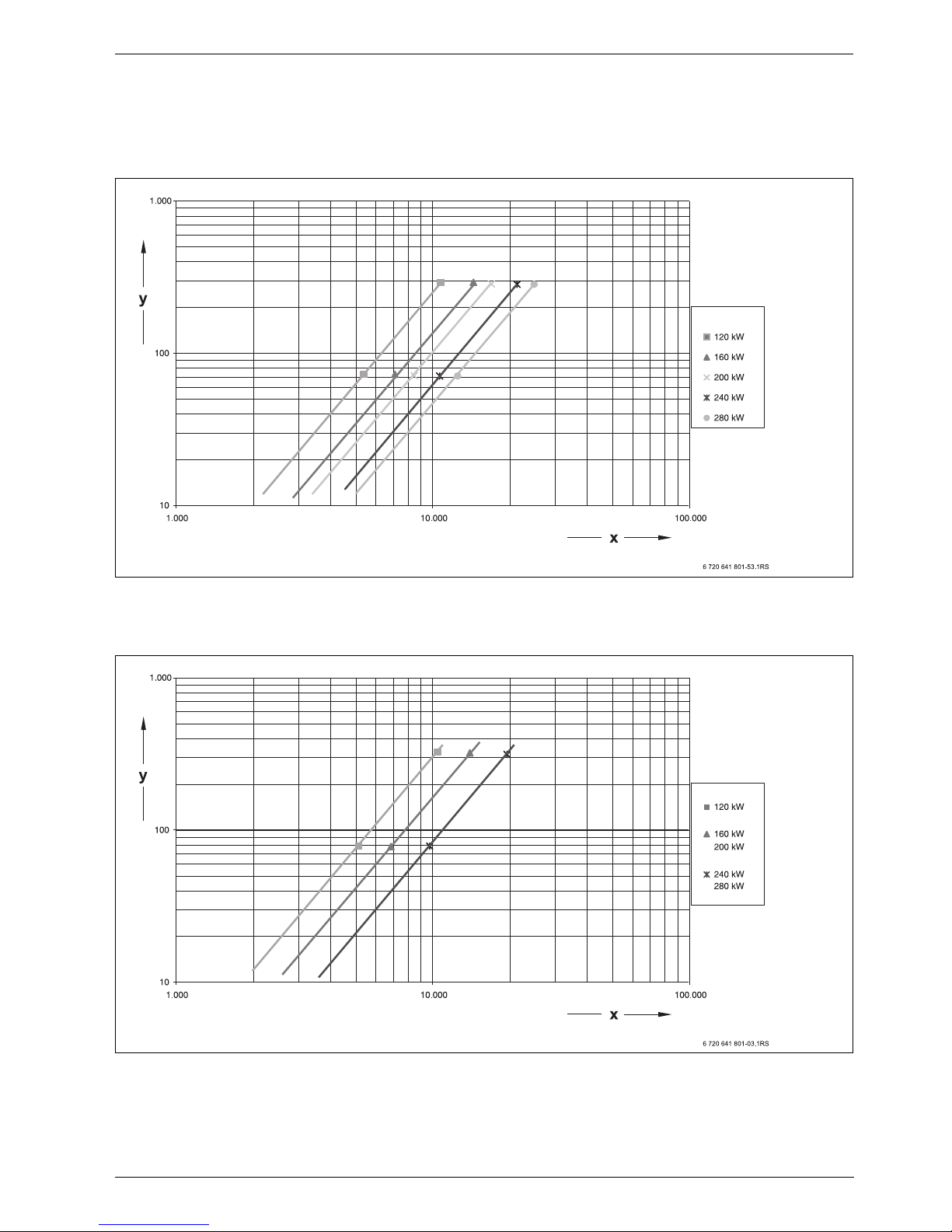
2.4 Pressure drop, water side
The pressure drop on the water side is the pressure
differential between the boiler flow and return
connections of the gas condensing boiler. It depends on
the boiler size and the heating water flow rate.
Fig. 14 Pressure drop on the heating water side without check valve
x Flow rate in l/h
y Pressure drop on the heating water side in mbar
Fig. 15 Pressure drop on the heating water side with check valve (cascade)
x Flow rate in l/h
y Pressure drop on the heating water side in mbar
Page 30
Specification
6 720 645 817 (2010/09)
30
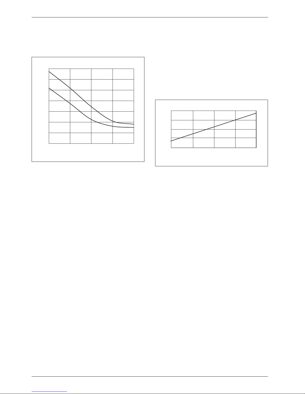
2.5 Boiler efficiency
The boiler efficiency ηK identifies the ratio of heat output
to heat input subject to the return temperature.
Fig. 16 Boiler efficiency subject to boiler return
temperature (average for this series of boilers)
ηKBoiler efficiency
ϑ Return temperature
1 Full load
2 Partial load
2.6 Standby loss
The standby loss qB is part of the rated heat input that
is required to achieve the specified boiler water
temperature. The cause of this loss is the cooling down
of the boiler through radiation and convection during the
standby time (burner idle time). Radiation and
convection result in part of the output being transferred
continuously from the boiler surface to the ambient air.
In addition to this surface loss, the boiler can also cool
down to a lesser degree through the chimney draught.
Fig. 17 Standby loss, relative to the rated heat input of
the boiler, subject to the average boiler water
temperature (average for this series of boilers)
qBStandby loss
ϑ
K
Average boiler water temperature
94
96
98
100
102
104
106
108
30 40 50 60 70
2
1
ηK [%]
ϑ [°C]
6 720 642 877-05.1il
0
0,1
0,2
30 40 50 60 70
qB [%]
ϑ
K
[°C]
6 720 642 877-06.1il
Page 31

Specification
6 720 645 817 (2010/09)
31
2.7 Flue gas temperature
The flue gas temperature ϑA is the temperature captured
inside the flue pipe, specifically at the boiler flue outlet.
It depends on the return temperature.
Fig. 18 Flue gas temperature subject to boiler return
temperature (average for this series of boilers)
ϑAFlue gas temperature
ϑ Return temperature
1 Full load
2 Partial load
2.8 Conversion factor for alternative
system temperatures
In the tables containing the technical details of the
Suprapur gas condensing boilers, the rated output
figures relate to system temperatures 50/30 °C and
80/60 °C.
Take a conversion factor into account when calculating
the rated output at different system temperatures.
Fig. 19 Conversion factor for deviating design return
temperatures (average of this series of boilers)
f Conversion factor
ϑ Return temperature
Example
For a Suprapur gas condensing boiler with a rated
output of 120 kW at a system temperature of 50/30 °C,
the rated output should be calculated at a system
temperature of 80/60 °C.
At a return temperature of 60 °C, a conversion factor of
0.935 results. At 80/60 °C, the rated output is therefore
112.2 kW.
30
35
40
45
50
55
60
65
70
30 40 50 60 70
2
1
80
75
ϑ
A
[°C]
ϑ [°C]
6 720 642 877-07.1il
0,93
0,94
0,95
0,96
0,97
0,98
0,99
1,00
30 35 40 45 50 55 60
f
ϑ [°C]
6 720 642 877-08.1il
Page 32

Appliance layout
6 720 645 817 (2010/09)
32
3 Appliance layout
Fig. 20
1 Main PCB with programming unit
2 Gas burner
3 Boiler front panel
4 Siphon
5 Boiler block with thermal insulation
6 Burner controller
7 Gas valve
8 Boiler casing
9 Check valve
Page 33

Product description
6 720 645 817 (2010/09)
33
4 Product description
4.1 Gas condensing boiler with aluminium heat exchanger
Fig. 21 Suprapur KBR ...
1 Boiler user interface
2 Modulating gas premix burner
3 High performance aluminium heat exchanger
4 Large inspection apertures
5 Neutralising system may be integrated
6 Variable speed combustion air fan
7 Burner control unit
The Suprapur is a floorstanding gas condensing boiler
with a high grade aluminium-silicon heat exchanger. Its
modulating gas premix burner enables clean combustion
and quiet operation. The modulation range from 25 % to
100 % or 30 % to 100 % provides optimum matching to
the required output. Balanced flue operation is possible
via an additional air inlet connector. Optimised heating
surfaces and specific water routing aid the achievement
of high standard seasonal efficiency [to DIN] and low
pressure drop on the water side.
The Suprapur gas condensing boilers are tested to
DIN-EN 677 and are CE-designated.
4.1.1 Types and output
The Suprapur gas condensing boiler is available as a
single boiler with output ranging from 120 kW to 280 kW
and as a factory-prepared cascade with output from
240 kW to 560 kW.
4.1.2 Possible applications
The Suprapur gas condensing boiler is suitable for all
heating systems compliant with DIN-EN 12828.
Preferred application areas are central heating and DHW
heating in apartment buildings as well as in municipal
and commercial buildings.
4.1.3 Benefits in brief
• Excellent price/performance ratio
• Easy system engineering, as no minimum water
circulation is required for single boiler systems
• Inexpensive operation due to high efficiency and low
power consumption
• Compact and light construction, consequently small
installation space
• Easy handling and easy and rapid installation through
complete pre-assembly at the factory and burner
tested at operating temperature, therefore ready for
use
• Extended application range through balanced flue
operation, quiet burner, and cascade operation with
up to eight boilers
• Easy and quick maintenance/service through large
cleaning apertures for the boiler block and the
condensate pan – easy burner removal
• Matching system technology from Junkers, e.g.
matching flue and ventilation accessories for easy and
rapid installation, as well as neutralising systems that
can be integrated, accessory no. 1605 and no. 1606
• Control systems for convenient operation of the
boiler and system plus easy monitoring by means of
the Service Diagnosis System (SDS)
6 720 643 417-12.1O
1
2
3
4
5
6
7
Page 34

Product description
6 720 645 817 (2010/09)
34
4.1.4 Characteristics and special features
Advanced boiler concept
• Heat exchanger made from high grade
aluminium-silicon sand casting
• Compact design and low weight
• Reduced pressure drop on the water side for
optimised and simple system technology
• With quiet modulating gas premix burner
• Low power consumption through variable speed fan
• With digital boiler and burner control units
• Suitable for new installations and modernisation
projects
Balanced flue
• Balanced flue operation possible (accessories)
High standard seasonal efficiency [to DIN] and
economic viability
• The optimised heating surfaces enable good heat
transfer with low flue gas losses and high condensing
output. This ensures high efficiency and good
economic viability. The result is standard seasonal
efficiency [to DIN] of up to 108 %.
• 4-star energy efficiency category to DIN-EN 483
Environmentally responsible
• Low nitrogen oxide emissions (standard emissions
factor < 45 mg/kWh). This corresponds to the highest
emissions category to DIN-EN 483 – category 5.
Advanced burner technology
• Modulating operation with digital combustion
management
• Very easy conversion to other gas types with only a
few steps
Matching system equipment
• Cascade solutions with up to eight boilers via a single
control system
• Matching flue gas and ventilation air systems
• Neutralising systems, accessories no. 1605 and
no. 1606, can be integrated inside the boiler,
consequently small installation space
Supplied fully wired ready for connection
• Easy connection to the heating system because of
fully assembled delivery from factory plus matching
accessories
4.2 Gas burner
4.2.1 Burner and burner control unit
A highly premixing modulating gas premix burner with
clean combustion is used in the Suprapur gas
condensing boiler. The gas burner comprises a fan, gas
valve and, subject to boiler size, several burner rods.
Features
• Emissions, NO
x
<45mg/kWh and CO<15mg/kWh
(standard emissions factors) comply with the highest
emissions category – category 5 to DIN-EN 483
• Suitable for natural gas H and L
• Easy conversion to other natural gas types possible
• Modulation range:
– KBR 120/160-3 A: 25 % - 100 %
– KBR 200/240/280-3 A: 30 % - 100 %
– MKB 240/320-3 A: 12,5 % - 100 %
– MKB 400/480/560-3 A: 15 % - 100 %
Burner control unit
• Burner control unit
• Burner control and monitoring
• Safety functions for boiler operation
• Flue gas temperature monitoring
• Setting parameters and issuing fault codes via the
control system
• Display and calling up operating, service and fault
displays via the Service Diagnosis System (SDS)
0-10 V interface (DDC systems)
• Connection possible via the ICM cascade module
• Output and temperature-dependent boiler controls,
selectable via settings on the ICM
Changeover or conversion to LPG operation
is not possible.
Page 35

Product description
6 720 645 817 (2010/09)
35
4.2.2 Burner function
The maximum ΔT between flow and return temperature
at rated output is 30 K.
From ΔT = 30 K, when no heat is being drawn off, the
burner modulates the boiler output down to the lowest
output. The boiler shuts down only if ΔT continues to rise
and exceeds 40 K.
If ΔT is too high, the boiler cannot transfer its maximum
output due to its safety circuit.
The restriction of the maximum temperature spread is
designed to ensure safety and the durability of the heat
exchanger.
Take the boiler characteristics into consideration during
system engineering.
4.3 Delivery method
The Suprapur is factory-fitted with check valve and is
delivered preset for natural gas H or L. This enables
rapid installation and easy, quick connection to the
heating system.
Conversion to a different gas type is easy.
The factory-prepared cascade solution is delivered in
modules (two boilers, hydraulic pipework and flue gas
cascade).
For optimum operational reliability and durability, the
flue gas cascade is designed as a negative pressure flue
gas cascade requiring no additional components
(shut-off dampers).
Page 36

Engineering information and sizing the heat source
6 720 645 817 (2010/09)
36
5 Engineering information and sizing the heat source
5.1 Operating conditions
Tab. 18 provides an overview of the conditions that must be observed, subject to the application and the local
system-specific circumstances.
5.2 Water quality
As there is no pure water for the heat transfer, observe
the water quality. Unsuitable water quality can damage
heating systems due to scaling and corrosion.
Fill the system with clean mains water only that meets
the requirements below.
To protect the appliance from scale damage throughout
its service life and ensure trouble-free, economical
operation, the overall quantity of hardness constituents
in the fill and top-up water of the heating circuit must be
limited.
To check the permitted amounts of water subject to the
fill water quality, either perform the following
calculations or consult the graphs.
Checking the maximum amounts of fill water subject to
water quality
The fill and top-up water has to meet certain
requirements depending on the total boiler output and
the resulting water volume of a heating system.
Use the following formula to calculate the maximum
amount of water that may be introduced without
treatment:
Form. 1 Calculation of the maximum amount of water that
may be introduced without treatment
Ca(HCO3)2Concentration calcium hydrogen carbonatein mol/m
3
Q Boiler output in kW
V
max
Maximum fill and top-up water over the entire service
life of the boiler in m
3
Information about the calcium hydrogen carbonate
(Ca(HCO
3)2
) concentration of the mains water can be
obtained from your water supply utility. If these details
are not included in the water analysis, the concentration
of calcium hydrogen carbonate can be calculated as
follows from carbonate hardness and calcium hardness.
Example
Calculation of the maximum permissible amount of fill
and top-up water V
max
for a heating system with a total
boiler output of 560 kW. The analysis values for
carbonate hardness and calcium hardness are quoted in
the older unit °dH.
Carbonate hardness: 15.7 °dH
Calcium hardness: 11.9 °dH
The following results from the carbonate hardness:
Ca(HCO
3)2
=15.7°dH×0.179 = 2.8mol/m
3
The following results from the calcium hardness:
Ca(HCO
3)2
=11.9°dH×0.179 = 2.13mol/m
3
The lower of the two values calculated from calcium and
carbonate hardness is decisive for calculating the
maximum permissible water volume V
max
.
Form. 2
Δϑ
max
Minimum
boiler water
flow rate
Max. water
flow rate
Minimum
boiler water
temperature
Operating
interruption
Heating circuit
control unit with
heating mixer
Minimum return
temperature
Full load = 30 K
Partial load = 40 K
No requirements
Results from
ΔT=8K
No requirements
To transfer the
max. output
ΔT must be < 30 K
Tab. 18 Suprapur operating conditions
V
max
0.0235
Q
Ca HCO
3
()
2
------------------------------- -
×=
.
V
max
0.0235
560 kW
2.13 mol/m
3
------------------------------- -
× 6.2 m
3
==
Page 37

Engineering information and sizing the heat source
6 720 645 817 (2010/09)
37
Limit curves
Fig. 22 Limit curves for water treatment – single boiler
Fig. 23 Limit curves for water treatment – factory-prepared 2-boiler cascade
Key to Fig. 22 and Fig. 23:
A Above the curves, water treatment is required
B Below the curves, fill with untreated mains water that meets the requirements of the Drinking Water Order [Germany]
H
W
Water hardness
V Water volume over the total service life of the boiler
0
1
2
3
4
5
6
7
0 5 10 15 20 25 30
280 kW
240 kW
200 kW
160 kW
120 kW
6 720 643 417-14.1O
V/m
3
HW/°dH
B
A
6 720 643 417-15.1O
V/m
3
HW/°dH
0
2
4
6
8
10
12
14
16
0 5 10 15 20 25 30
560 kW
480 kW
400 kW
320 kW
240 kW
B
A
Page 38

Engineering information and sizing the heat source
6 720 645 817 (2010/09)
38
Water treatment measures
There are two methods for treating the fill and top-up
water for Suprapur gas condensing boilers:
• Use of fully desalinated fill water with a conductivity
of ≤ 10 μS/cm:
During the total desalination of the fill and top-up
water, not only the causes of hardness (Ca, Mg) but
also all other minerals are removed. This significantly
reduces the conductivity of the fill and top-up water.
The likelihood of corrosion forming shrinks as the conductivity of the heating water drops. Operation with a
low salt content will at the same time reduce corrosion in the heating system.
• Use of partially softened fill and top-up water based
on sodium ion exchangers:
The fill and top-up water must have a residual
hardness of 5 °dH to 7 °dH.
Only use chemicals approved by Junkers.
Additional protection against corrosion
Damage through corrosion occurs if oxygen constantly
enters the heating water, for example through
inadequately sized or faulty expansion vessels (MAG) or
open vented systems.
If a sealed unvented heating system is not feasible,
corrosion protection measures are required, e.g. by
adding approved chemicals or by system separation
through the use of a heat exchanger.
Installation in existing heating systems/dirt traps
If the gas condensing boiler is installed in an existing
heating system, impurities may build up in the boiler,
leading to local overheating, corrosion and noise.
We therefore recommend the installation of a dirt trap
and blow-down facility. This should be installed
immediately between the boiler and the lowest position
with good accessibility, and should be cleaned during
every service.
Estimate of system capacity
Especially with older systems, the water capacity of the
entire system is often not known. The following graph
gives an estimate of the system capacity.
Fig. 24 Estimated water capacity of the system with
known system output
Q Total system output
V Water capacity
1 Steel/cast iron radiators with pipes sized for gravity
circulation and underfloor heating (20 l/kW)
2 Panel radiators (10 l/kW)
3 Convectors (6 l/kW)
0
1
2
3
4
5
6
7
8
9
10
11
12
0 100 200 300 400 500 600
1
2
3
V
[m
3
]
Q
[kW]
6 720 642 877-13.1il
.
Page 39

Engineering information and sizing the heat source
6 720 645 817 (2010/09)
39
5.3 Important hydraulic system components
5.3.1 Hydraulics for maximum utilisation of the
condensing effect
For systems where the heating circuits are connected via
a low loss header, we recommend that the pump is
controlled subject to boiler output. This operating
principle enables the system to operate with maximum
utilisation of the condensing effect.
5.3.2 Underfloor heating system
Due to their low design temperatures, underfloor
heating systems are ideal for combination with a
Suprapur gas condensing boiler. Due to the inertia
during heat-up, we recommend weather-compensated
operation combined with a separate flow
rate-dependent room temperature controller. In
conjunction with the boiler control unit, the FW ...
controllers are suitable for this purpose.
A temperature limiter is required to protect the
underfloor heating system. It should be connected to the
IPM ... For the temperature limiter, contact thermostat
TB 1 can be used, for example.
Automatic system-controlled screed drying is not
possible here, and should therefore be allowed for on
site. Automatic screed drying with the FW ... controller is
only possible via an underfloor heating circuit with
mixer.
5.3.3 Diaphragm expansion vessel
In accordance with DIN EN 12828, water heating
systems must be equipped with a diaphragm expansion
vessel (MAG).
Rough guide to selecting a diaphragm expansion vessel
1. MAG pre-charge pressure
Form. 3 Formula for the MAG pre-charge pressure
(minimum 0.5 bar)
p0Pre-charge pressure of the MAG in bar
p
st
Static pressure of the heating system in bar (subject to
building height)
2. System fill pressure
Form. 4 Formula for the system fill pressure
(minimum 1.0 bar)
paSystem fill pressure in bar
p0Pre-charge pressure of the MAG in bar
3. System volume
Subject to various heating system parameters, the
system volume can be checked on the graph in Fig. 25.
4. Maximum permissible system volume
Subject to a maximum flow temperature to be set ϑ
V
and
the pre-charge pressure determined according to
formula 3 p
0
of the MAG, the permissible maximum
system volume for various MAG can be checked in
table 19.
The system volume checked acc. to point 3 in Fig. 25
must be smaller than the maximum permissible system
volume. Select a larger diaphragm expansion vessel if
that is not the case.
Example 1
Given
n System output Q
K
= 200 kW
o Underfloor heating/radiators
Actual
p Total system water content = 4000 l
(Æ Fig. 25, curve a)
Fig. 25 Standard values for average water content of
heating systems
a Underfloor heating system and steel/cast iron radiators
with pipes sized for gravity circulation (20 l/kW)
b Panel radiators (10 l/kW)
c Convectors (6 l/kW)
V
A
Average total water content
Q
K
Rated output
Always use the Suprapur gas condensing
boilers with a low loss header.
p0pst=
pap00.5 bar+=
.
0
1
2
3
4
5
6
7
8
9
10
11
12
0 100 200 300 400 500 600
a
b
c
VA / m
3
Q
K
/ kW
.
6 720 643 417-29.1O
.
Page 40

Engineering information and sizing the heat source
6 720 645 817 (2010/09)
40
Example 2
Given
n Flow temperature (Æ table 19): ϑ
V
=50°C
o MAG pre-charge pressure (Æ table 19): p
0
=1.00bar
from example 1: system volume: V
A
=4000l
Actual
p A M AG w it h 2 00 l c ap ac it y i s required (Æ table 19), as
the system volume determined in accordance with
Fig. 25 is smaller than the maximum permissible system
volume.
Flow temperature
ϑ
V
Pre-charge pressure
p
0
Diaphragm expansion vessel
80 l 100 l 150 l 200 l
Maximum permissible system volume V
A
°C bar l l l l
90 0.75 960 1200 1800 2400
1.00 850 1050 1575 2100
1.25 705 882 1323 1764
1.50 563 704 1056 1408
80 0.75 1155 1444 2166 2888
1.00 1020 1276 1914 2552
1.25 851 1064 1596 2128
1.50 681 852 1278 1704
70 0.75 1417 1772 2658 3544
1.00 1251 1564 2346 3128
1.25 1043 1304 1956 2608
1.50 835 1044 1566 2088
60 0.75 1792 2240 3360 4480
1.00 1580 1976 2964 3952
1.25 1315 1644 2466 3288
1.50 1052 1316 1974 2632
50 n 0.75 2326 2908 4362 5816
1.00 o 2054 2568 3852 5136 p
1.25 1712 2140 3210 4280
1.50 1369 1712 2568 3424
40 0.75 3107 3884 5826 7768
1.00 2742 3428 5142 6856
1.25 2284 2856 4284 5712
1.50 1827 2284 3426 4568
Tab. 19 Maximum system volume subject to the flow temperature and the required MAG pre-charge pressure.
Page 41

Engineering information and sizing the heat source
6 720 645 817 (2010/09)
41
5.4 Condensate drainage
Route the condensate from condensing boilers correctly
into the public sewage system. It is essential to
determine whether the condensate must be neutralised
prior to discharge into the sewer system. This depends
on the boiler output and the relevant regulations of the
local water authority (Æ table 20). In Germany, the Code
of Practice ATV-DVWK-A 25 of the Deutsche Vereinigung
für Wasserwirtschaft, Abwasser und Abfall e.V (DWA)
applies for the calculation of the amount of condensate
created per annum. This Code of Practice lists a specific
amount of condensate as an empirical value for natural
gas, i.e. a maximum of 0.14 kg/kWh.
Form. 5 Accurate calculation of the condensate volume
per annum
bVHBoiler hours in full use (full load) in h/a
m
K
Specific condensate volume in kg/kWh
(assumed density = 1 kg/l)
Q
F
Rated heat input of the heat source in kW
V
K
Condensate flow rate in l/h
Neutralising obligation
Materials for condensate lines
Suitable materials for condensate lines in accordance
with DWA Code of Practice ATV-DVWK-A 25 [Germany]
are the following:
• Earthenware pipes (to DIN EN 295-1)
• Rigid PVC pipes
• PVC pipes (polyethylene)
• PE-HD pipes (polypropylene)
• PP pipes
• ABS-ASA pipes
• Stainless steel pipes
• Borosilicate glass pipes
If admixing of the condensate with domestic waste
water in a ratio of at least 1:25 is assured (Æ table 21),
then the following may be used:
• Fibre cement pipe
• Cast iron or steel pipes to DIN 19522-1 and
DIN 19530-1 and 19530-2
Copper pipes are unsuitable for draining condensate.
Adequate admixing
Adequate admixing of the condensate with domestic
waste water is given when the conditions in table 21 are
met. The details refer to 2000 hours of full utilisation in
accordance with guideline VDI 2067 (maximum value).
It is advisable to check local regulations on
draining condensate in good time prior to
installation. The local water supply utility is
the responsible body for questions
concerning waste water.
Boiler output in kW Neutralisation
> 25 to ≤ 200 no
1)
1) Neutralisation of the condensate is required for buildings
where the requirement of adequate admixing (Æ table 21)
with domestic waste water (at a ratio of 1:25) is not met.
> 200 yes
Tab. 20 Neutralising obligation for gas condensing boilers
VKQFmK× b×
VH
=
.
.
Boiler load
Boiler
output
kW
1)
1) Rated heat input
Volume of
condensate
2)
m3/a
2) Maximum values at a system temperature 40/30 °C and
2000 hours run
Office and
commercial
buildings
2)
Number of
employees
Residential
building
2)
Number of
residential
units
100 28 ≥ 40 ≥ 4
150 42 ≥ 60 ≥ 6
200 56 ≥ 80 ≥ 8
Tab. 21 Conditions for adequate admixing of condensate
with domestic waste water
Page 42

Engineering information and sizing the heat source
6 720 645 817 (2010/09)
42
5.4.1 Condensate drain from the condensing boiler
and the flue
To ensure the condensate created in the flue can drain
via the condensing boiler, route the flue inside the
installation room with a slight fall (≥ 3°, i.e. approx. 5 cm
height differential per metre) towards the gas
condensing boiler.
Fig. 26 Condensate drain from the gas condensing boiler
and a flue via the neutralising system
NE Neutralising system
5.4.2 Condensate drain from a moisture-resistant
chimney
With moisture-resistant chimneys (suitable for
condensing boilers), drain the condensate in
accordance with the chimney manufacturer's
instructions.
Via a stench trap with funnel, the condensate from the
chimney can be routed into the building drain together
with the condensate from the gas condensing boiler.
Observe all relevant regulations concerning
the building's drains, as well as local
regulations. Ensure particularly that the
drain line is vented in accordance with
regulations and that it terminates freely in a
drain outlet with a siphon (Æ Fig. 26). As a
result, the stench trap cannot be drained,
and backing up of condensate inside the
appliance is prevented.
6 720 643 417-26.1O
NE
3°
Page 43

Regulations and operating conditions
6 720 645 817 (2010/09)
43
6 Regulations and operating conditions
6.1 Extracts from regulations
The Suprapur gas condensing boilers meet the
requirements of DIN-EN 677, the EC Efficiency Directive,
the Gas Appliances Directive and the EMC/LV Directive.
Observe the following regarding creation and operation
of the system:
• Technical building rules
• Legal regulations
• Local regulations
Installation, gas connection, flue gas connection,
commissioning, power supply, maintenance and repair
wo rk m us t o nl y b e carried out by author ise d c on tr ac to rs.
Permits
The installation may need to be notified to and approved
by the relevant gas supply utility.
We recommend clarifying the match between boiler and
flue system with the relevant bodies at the planning
stage.
Notify the relevant issuing authority prior to
commissioning. It may be necessary to obtain a permit
for the flue system and the condensate line to the public
sewer system at regional level.
Inspection/maintenance
Keep the system in good order and clean it regularly
(recommendation: every two years). The entire system
should be checked annually for perfect function.
Regular inspection and, if required, maintenance are
prerequisites for safe and economical operation.
6.2 Fuels
The Suprapur gas condensing boilers are suitable for
natural gas H or L.
The gas quality must comply with the requirements of
the DVGW Code of Practice G 260 [German y]. In dustr ial
gases containing sulphur are unsuitable for the gas
burner.
The supply pressure must lie within the range specified
for each gas type. The supply pressure is the flow
pressure at the gas connection of the boiler.
If the supply pressure for the gas type used exceeds the
value in the table, install an additional gas pressure
regulator upstream of the boiler.
6.3 Operating conditions
Gas type Supply pressure
p
min
p
nom
p
max
[mbar] [mbar] [mbar]
Natural gas H 18 20 24
Natural gas L 18 20 24
Tab. 22 Supply pressures for different gas types
Δϑ
max
Minimum
boiler water
flow rate
Max. water
flow rate
Minimum
boiler water
temperature
Operating
interruption
Heating circuit
control unit with
heating mixer
Minimum return
temperature
Full load = 30 K
Partial load = 40 K
No requirements
Results from
ΔT=8K
No requirements
To transfer the
max. output
ΔT must be < 30 K
Tab. 23 Suprapur operating conditions
Page 44

Regulations and operating conditions
6 720 645 817 (2010/09)
44
6.4 Combustion air
Where combustion air is concerned, ensure that it is not
heavily contaminated with dust and contains no
halogenated compounds. Otherwise there would be a
risk of damage to the combustion chamber and the
secondary heating surfaces. Halogenated compounds
are highly corrosive. These can be contained in spray
cans, thinners, cleaning & degreasing agents and
solvents. Design the combustion air supply so that, for
example, no extract air is drawn in from chemical
cleaners or paint shops. Special requirements apply to
the supply of combustion air in the installation room.
The Suprapur gas condensing boiler is prepared for
balanced flue operation. Balanced flue operation is
possible via the connection set. This is also appropriate,
for example, if the combustion air could be
contaminated.
Routing flue gas in chimney shafts with secondary
ventilation
No cleaning is required if the flue gas is routed through
a chimney shaft with secondary ventilation (Æ Fig. 48 on
page 80).
Routing air and flue gas in countercurrent
Clean the chimney shaft as follows if the combustion air
supply is drawn through the shaft in a countercurrent
(Æ Fig. 52 on page 88):
If dust loads due to fragile chimney pointing are to be
expected, also clean and seal the chimney shaft.
6.5 Combustion air supply
The conditions of installation rooms and the siting of gas
appliances must comply with country-specific
regulations.
For open flue combustion equipment with a total rated
output in excess of 50 kW, the combustion air supply is
deemed to be ensured if an aperture to the outside with
a clear opening of at least 150 cm
2
(plus 2 cm2 for every
kilowatt output above 50 kW rated output) is provided.
The required cross-section may be split over up to two
lines and must be sized to provide the equivalent air flow
rate.
General requirements
• Combustion air vents and lines must never be closed
or covered if appropriate safety equipment cannot
ensure that the combustion equipment can only
operate when the flow cross-section is free.
• The required cross-section must not be restricted by
a closure or grille.
• An adequate supply of combustion air can also be
verified by other means.
Previous use of the
chimney shaft/
chimney
Required cleaning
Ventilation shaft Thorough mechanical
cleaning
Routing flue gas from
gas combustion
Thorough mechanical
cleaning
Routing flue gas from
oil or solid fuel
Thorough mechanical
cleaning; sealing the surface
to prevent vapour from
residues (e.g. sulphur) in the
brickwork permeating the
combustion air
Tab. 24
To avoid having to seal the chimney shaft:
Choose open flue operation or draw in
combustion air via a coaxial pipe inside the
chimney shaft or a separate pipe from
outside.
Page 45

Regulations and operating conditions
6 720 645 817 (2010/09)
45
6.6 Siting combustion equipment
Subject to the regulations of the relevant country, gas
combustion equipment with a total rated output in
excess of 50 kW may only be installed in rooms:
• that are not used for any other purpose
• that have no opening towards other rooms, except
doors
• the doors of which are tight and self-closing or
• that can be ventilated.
Notwithstanding these rules, combustion equipment
may also be installed in other rooms, if:
• the use of these rooms makes this necessary and the
combustion equipment can be operated safely or
• the rooms are in freestanding buildings that only
serve to operate the combustion equipment and fuel
storage.
Open flue combustion equipment must not be installed:
• in stairwells, except in residential buildings with no
more than two apartments
• in generally accessible hallways that serve as escape
routes or
• in garages.
Rooms with systems that extract air
Open flue combustion equipment must only be installed
in rooms equipped with systems that extract air subject
to the following conditions:
• simultaneous operation of the combustion equipment
and the air extractor systems will be prevented by
safety equipment
• the flue gas routing will be monitored by appropriate
safety equipment or
• flue gas will be routed via the air extractor systems or
it will be ensured that such systems cannot create
dangerous negative pressure.
6.7 Sound insulation
The quiet gas premix burner in the Suprapur generates
only low noise emissions, compared to conventional
pressure-jet gas burners. This generally makes
additional sound insulation measures to ensure airborne
noise inside the installation room superfluous. The
transmission of structure-borne noise is largely
prevented by the standard adjustable feet supplied.
Nevertheless, pumps and other system components can
cause structure-borne noise. Where required, this can
be addressed by the use of compensators and other
measures designed to reduce the transmission of
structure-borne noise. Further on-site measures can be
implemented if the aforementioned measures are
inadequate and more stringent requirements for noise
protection apply.
6.8 Antifreeze
The antifreeze Antifrogen N is approved for use in the
Suprapur series. Observe the manufacturer's
instructions.
When pumping liquids with viscosities that differ from
that of water, the hydraulic performance of pumps and
the pipework will also be different. For further details on
sizing pumps, see the technical guides published by the
pump manufacturers.
For further information on the siting and
installation of gas combustion equipment,
see country-specific regulations. These
must also be observed.
Page 46

Accessories / Services
6 720 645 817 (2010/09)
46
7 Accessories / Services
7.1 Neutralising systems
Neutralising systems no. 1605 and no. 1606 can be used
if the condensate needs to be neutralised. Install these
between the condensate outlet from the gas condensing
boiler and the connection to the public sewer system.
Site the neutralising system behind or adjacent to the
gas condensing boiler.
The neutralising systems no. 1605 and no. 1606 can be
integrated in the Suprapur condensing boilers.
Create the condensate drain with suitable materials, e.g.
PP plastic.
The neutralising system is filled with neutralising
granulate. Through contact between the condensate and
the neutralising agent, the condensate pH level will be
raised to between 6.5 and 10. At this pH level, the
neutralised condensate can be introduced into the
domestic waste water system. How long one filling of
granulate remains effective depends on the amount of
condensate to be treated and the neutralising system.
Replace the spent neutralising granulate when the pH
level of the neutralised condensate falls below 6.5.
Check the pH value of the neutralised condensate at
least twice annually.
7.1.1 Neutralising system no. 1605
The neutralising system no. 1605 comprises a plastic
casing with a chamber to hold the neutralising granulate.
It may be used with systems where a lower connection
to the waste water system or an external pump station
is available for the neutralised condensate. A power
supply is not required. It is possible to neutralise
condensate volumes up to approx. 800 kW rated output.
Fig. 27
1 Neutralising box with lid (L × W × H) 400 × 300 × 220 mm
2 Fill chamber with neutralising granulate (10 kg)
3 Inlet connector G1
4 Filter pipe
5 Drain connector G1
6 Filter pipe
7 Protective cap
8 Flat gasket Ø 30 × 19 × 2 mm
9 Hose ferrule DN 19 with union nut G1
10 Hose clip Ø 20 - 32 mm
11 Supply hose DN 19 × 1.5 m long
12 Drain hose DN 19 × 1.0 m long
13 Cover
1
10
4
311 10 9 8 7
2
6
9875
12
13
102
43
6 720 619 379-59.1O
Page 47

Accessories / Services
6 720 645 817 (2010/09)
47
7.1.2 Neutralising system no. 1606
The neutralising system no. 1606 comprises a plastic
casing with a chamber to hold the neutralising granulate,
a back-up area for the neutralised condensate and a
level-controlled condensate pump with a head of
approx. 2.0 m. No. 1606 enables the neutralisation of
condensate volumes from systems with up to approx.
850 kW rated output. The neutralising system no. 1606
is equipped with a stand-alone 230 V power supply.
Fig. 28
1 Connection plug
2 Condensate inlet (DN 20, 3/4" hose fitting)
3 Condensate drain (DN 20, 3/4" hose fitting)
4 Neutralising agent
5 Condensate pump
6 Pressure switch for starting and stopping the condensate
pump plus additional pressure switch for switching off the
burner if the max. level has been exceeded
7 Condensate chamber
Condensate pump
The amount of condensate determines the head of the
condensate pump.
The graph shows the heat of the neutralising system
no. 1606 subject to the pump rate.
Fig. 29
H Delivery head
V Flow rate
7.1.3 Condensate lifting system no. 1620
The condensate lifting system no. 1620 was designed for
installation inside condensing boilers where corrosive
condensate according to the DWA Code of Practice
ATV-DVWK-A 25 is generated. The materials used in the
system permit the routing of condensate with a pH value
≥ 2.4 without any problem. For oil or gas condensing
boilers with an output > 200 kW, install the lifting system
downstream of the neutralising system.
The drive unit can be reversed on top of the tank and
thereby enables a variable supply and drain
arrangement.
The fully wired lifting system is equipped with a
standard alarm contact (NC/NO) for connection to a
condensing boiler or to an alarm controller.
6 720 619 379-60.1O
0,0
0,5
1,0
1,5
2,0
2,5
5550454035302520151050
H
/ m
V
/ l/min
.
6 720 619 379-62.1O
.
No. 1620
Loaded condensate (pH ≥ 2.4) – permissible
Power supply V 1~230
Connected load P
1
kW 0.08
Rated current A 0.8
Mains frequency Hz 50
Cable length, system to
controller / plug
m 2
Maximum media temperature °C 80
Pressure connection mm 12
Inlet connection mm 19/24
IP rating – IP20
Gross volume l 1.5
Weight kg 2
Tab. 25 Specification condensate lifting system no. 1620
Page 48

Accessories / Services
6 720 645 817 (2010/09)
48
Fig. 30 Residual head no. 1620
H Residual head
V Flow rate
Fig. 31 Dimensions no. 1620 (dim. in mm)
7.2 Pumps
Size pumps in central heating systems in accordance
with current technical rules.
The sizing of pumps to be used on site depends on the
pressure drop of system and boiler (Æ chapter 2.4,
page 29) and the required pump rate.
7.3 Dirt traps
Deposits in heating systems can lead to local
overheating, noise and corrosion. Any resulting boiler
damage falls outside the warranty obligations.
To remove dirt deposits, flush the new heating system
thoroughly prior to installing and commissioning a
boiler. In addition, we recommend the installation of dirt
traps or a blow-down facility.
Dirt traps retain contaminants and thereby prevent
operating faults in control devices, pipework and
boilers. Fit these near the lowest point of the heating
system in an easily accessible position. Clean the dirt
traps every time the heating system is serviced.
7.4 Low loss header
Subject to the amount of water on the primary and
secondary sides, a lower flow temperature than that
supplied by the boiler itself can be provided if a low loss
header is installed (Æ Fig. 32).
This is the case if the water volume on the secondary
side is greater than that on the primary side. This is used
frequently with gas condensing boilers to prevent a
raising of the return temperature. This leads to a
reduction of the maximum possible flow temperature.
Take this into account when sizing the boiler. For
information, see table 26.
Fig. 32 Use of a low loss header
VF Low loss header sensor
I Primary side
II Secondary side
0
2
4
3
5
6
1
7
0
50
100 150
200
250 300
350 400
V
/ l/min
H
/ m
.
6 720 619 379-56.1O
.
21
Ø12
195
169,5130
82,5
6 720 619 379-57.1O
≤ 85 °C
≤ 75 °C
60 °C
60 °C
ΔT = 25 K
ΔT = 15 K
VF
III
6 720 643 417-25.1O
Page 49

Accessories / Services
6 720 645 817 (2010/09)
49
7.5 Boiler safety set
A factory-prepared boiler safety set is available for the
Suprapur KBR ...
This set comprises the following:
• Pressure gauge
• Safety valve R 1 (for boiler size 120 kW)
• Safety valve R 1¼ (for boiler sizes 160 kW to 280 kW)
• Automatic air vent valve
• Insulation, grey
Fig. 33 Boiler safety set
7.6 Safety equipment to DIN-EN 12828
As standard, the Suprapur KBR ... is equipped with a low
water indicator (minimum pressure switch) and boiler
drain & fill valve.
Fig. 34 Safety equipment to DIN EN 12828 for boilers
≤
300 kW, operating temperature ≤ 105 °C
RK Boiler return
VK Boiler flow
1 Heat source
2 Shut-off valve, flow/return
3 Temperature controller (TR)
4 High limit safety cut-out (STB)
5 Temperature capturing facility
6 Diaphragm safety valve MSV 2.5 bar/3.0 bar or
7 Lift spring, safety valve HFS 2.5 bar
8 Pressure gauge
9 Low water indicator (WMS); not in systems ≤ 300 kW,
where instead a minimum pressure limiter or a replacement
measure approved by the manufacturer is provided for each
boiler
10 Non-return valve
11 Boiler drain & fill valve (KFE)
12 Expansion line
13 Shut-off valve - locked to prevent unintentional closure,
e.g. sealed cap valve
14 Drain upstream of diaphragm expansion vessel
15 Diaphragm expansion vessel (DIN-EN 13831)
1) At a shutdown temperature (STB) of 100 °C, the maximum
flow temperature would be 85 °C
The maximum flow temperature drops
through mixing to a lower temperature level
in the low loss header.
Max. boiler
flow
temperature
ΔT on
primary
side of low
loss header
ΔT on
secondary
side of low
loss header
Max. flow
temperature
for heating
system
[°C] [K] [K] [°C]
85 25
10 70
15 75
20 80
25 85
85 20
10 75
15 80
20 85
85 15
10 80
15 85
85 10 10 85
Tab. 26 Maximum possible flow temperature when using a
low loss header
6 720 619 235-119.1il
2
9
8
13
15
6/7
10
11
12
13
14
15
2
11
RK
VK
5
1)
4
1)
3
1)
1
≤ 300 kW
6 720 642 877-32.1il
Page 50

Accessories / Services
6 720 645 817 (2010/09)
50
7.7 Shut-off set combined with check
valve
Fig. 35 Shut-off valve
VK Flow with flange, welded to the boiler
1 Nut
2 Gasket
3 Shut-off valve
4 Check valve
5 Flow piece in cascade pipework
When using shut-off valves, install the check valve in the
flow direction downstream of the shut-off valve.
7.8 Boiler flue connection
Special boiler flue connections made from translucent
PP are available for the Suprapur KBR ... to provide a
connection between the boiler and flue system.
The boiler flue connections are available in a straight
version (KAS) and in an 87° version (boiler flue
connection bend KAB), in size DN 160 for boilers with
120 kW and 160 kW output as well as DN 200 for boilers
with 200 kW to 280 kW output. Boiler flue connections
are already part of the factory-prepared cascade packs.
The boiler flue connections provide a test port and a
condensate connector for draining the condensate
created in the flue system. As standard, a piece of hose
with threaded fittings is supplied for the condensate
drain. This can be easily connected with the boiler
siphon (threaded fittings).
If no boiler flue connections are used, ensure the
draining of condensate from the flue system on site.
Adaptors or reducers are available for alternative
connection diameters.
7.9 Ventilation air connection bend
A connection bend for balanced flue operation is
available in translucent PP for the Suprapur KBR ...
The connection bend DN 110 has an angle of 90° and a
test port.
Adaptors are available for larger dimensions.
7.10 Cleaning tool
A special cleaning tool is available for the Suprapur
KBR ...
This cleaning tool can be used to back up other cleaning
methods when there are resistant deposits inside the
boiler.
Generally, the system is cleaned by flushing with tap
water and blowing compressed air through the heat
exchanger and burner. In the case of severe
contamination, cleaning agents approved by Junkers can
be used. Check with Junkers for details.
7.11 Services
Junkers offers setup optimisation for the gas burner,
boiler and the control unit parameters as part of the
commissioning service. Commissioning requires a
natural gas connection, and adequate heat transfer must
be ensured.
In addition, there is the option of supplying a mobile
water treatment plant to reduce the hardness of the fill
water for the system in accordance with Junkers
requirements.
If required, please contact out customer service
(Æ back page).
6 720 642 877-17.1il
1
VK
2
3
2
4
2
5
Page 51

Heating controls
6 720 645 817 (2010/09)
51
8 Heating controls
A control unit is required to operate gas condensing
boilers. The Junkers control systems are of modular
design. This enables the system to be matched
inexpensively to the individual application and
equipment installed in the planned heating system.
8.1 Selection aids for controller application
The Suprapur gas condensing boilers are factory-fitted
with a BUS-enabled boiler control unit and without a
separate controller. Subject to application, there are
different controllers available for operating the
condensing heating system.
The room temperature-dependent and
weather-compensated controllers communicate with
the boiler control unit via the 2-wire BUS system. Up to
32 subscribers can be connected to this BUS to
exchange data; these might be controllers, function
modules and/or remote controls.
The weather-compensated controllers in particular
stand out thanks to their flexible use. They may be
mounted on the wall next to the boiler and can be
controlled from any other room using a remote control.
On the other hand, the room temperature-dependent
controller must be installed inside the room that is
decisive for the temperature (lead room).
Controllers are selected subject to the demand profile
and their respective performance. The following
overview shows which controller can meet the essential
requirements and which further function modules are
required to achieve the stated aims.
The overview enables a preselection of the controller
system. The applications shown represent standard
cases. Finally, the control system must be suited to the
hydraulic system conditions. Generally, we would
recommend using a weather-compensated controller
when utilising a condensing system. This method of
control minimises the return temperature via a variable
flow temperature, thereby optimising the utilisation of
condensing benefits.
Fig. 36
Extended functionality and controllers
Subject to the selected controller, the following
functions are available:
• Solar-optimised DHW heating
• Solar-optimised heating circuit
• Heat-up speed selection
• Thermal disinfection
• Screed drying
• Optimised heating curves for different types of
heating system (radiators, convector heaters,
underfloor heating)
• Pump economy function
• Display of the solar yield by the controller
• Extended fault recognition regarding system and
installation
• Controlling DHW circulation
Page 52

Heating controls
6 720 645 817 (2010/09)
52
8.2 Overview of the BUS-regulated controller functions
Weather-compensated controller
Controller FW 100 FW 200 FW 500
1 unmixed heating circuit y y y
1 mixed heating circuit
y
(with IPM 1)
y
(with IPM 1)
y
(with IPM 1)
2 mixed heating circuits –
y
(with IPM 2)
y
(with IPM 2)
4 mixed heating circuits –
y
(with 2 IPM 2+ 2 FB 100)y (with 2 IPM 2+ 2 FB 100)
10 mixed heating circuits – –
y
(with 5 IPM 2+ 8 FB 100)
DHW heating via cylinder
(time program)
y
(with IPM 1)
y
(with IPM 1)
y
(with IPM 1)
Control of several DHW
cylinders (time program)
– –
y
(with IPM 2)
DHW circulation (time
program)
y y y
Solar DHW heating
y
(with ISM 1)
y
(with ISM 1)
y
(with ISM 1)
Solar central heating backup +
DHW heating
–
y
(with ISM 2)
y
(with ISM 2)
Cascade circuit with
up to 4 appliances
–
y
(with ICM)
y
(with ICM)
Screed drying program y y y
Automatic summer/winter
changeover
y y y
Thermal disinfection y y y
Solar optimisation -
DHW heating
y y y
Solar optimisation heating circuit
y y y
Convector heater and
swimming pool control
– –
y
(with IEM)
Heat-up optimisation – – –
Room temperature hook-up y y y
Heating curve optimisation y y y
Remote management
(Netcom 100)
y y y
System info y y y
Holiday function y y y
Tab. 27
Page 53

Heating controls
6 720 645 817 (2010/09)
53
8.3 Weather-compensated controllers
FW 100 Application
• Weather-compensated flow temperature controller
• Constant output control
• Communication with the heat source via 2-wire BUS
Function
• 2-wire BUS technology, reverse polarity protected connection
• Controls one mixed or unmixed heating circuit
• DHW program for DHW cylinder (adjustable time and temperature)
• Solar DHW heating (with ISM 1)
• Solar-optimised heating circuit and DHW heating as options
• Optional FB 10 or FB 100 remote controls
• 7-day program with six switching times per day for one mixed or one unmixed heating
circuit and DHW heating
• Date and time, automatic summer/winter changeover
• Fault codes displayed in plain text
• Switching modules IPM 1, ISM 1 (for mixed heating circuit, solar DHW heating)
• Preinstalled programs adjustable to customer's requirements
• Holiday function with date entry
• Intuitive menu prompts with plain text support
• Thermal disinfection possible
• DHW circulation pump program
• Screed drying program
• Room temperature hook-up
• Optimised heating curves
• Adjustable heat-up speed (slow, normal, fast)
• Info function
• Remote management via Netcom 100
Installation
• Wall mounting (height/width/depth: 119/134/45 mm)
• Power supply 15 V via 2-wire BUS
Accessories
• IPM 1 load switching module
• ISM 1 solar module
• FB 10 remote control
• FB 100 remote control with plain text display
Part no. 7 719 002 923
Tab. 28
Page 54

Heating controls
6 720 645 817 (2010/09)
54
FW 200 Application
• Weather-compensated flow temperature controller
• Constant output control
• Communication with the condensing boiler via 2-wire BUS
Function
• 2-wire BUS technology, reverse polarity protected connection
• Controls two mixed heating circuits without remote control
• Up to four mixed heating circuits possible (FW 200 + FB 100 + two IPM 2)
• DHW program for DHW cylinder (adjustable time and temperature)
• Solar DHW heating (with ISM 1)
• Solar central heating backup (with ISM 2)
• Cascade circuit (up to four appliances)
• Optional solar optimisation of heating circuit and DHW
• Optional FB 10 or FB 100 remote controls
• 7-day program with six switching times per day for two heating circuits (mixed or
unmixed) and DHW heating
• Date and time, automatic summer/winter changeover
• Fault codes displayed in plain text
• Switching of IPM1, IPM2, ISM1 and ISM2 modules (for two mixed heating circuits,
solar central heating backup)
• Preinstalled programs adjustable to customer's requirements
• Holiday function with date entry
• Intuitive menu prompts with plain text support
• Thermal disinfection possible
• DHW circulation pump program
• Screed drying program
• Room temperature hook-up
• Optimised heating curves
• Heat-up optimisation and adjustable heat-up speed (slow, normal, fast)
• Info function
• Remote management via Netcom 100
Installation
• Wall mounting (height/width/depth: 119/134/45 mm)
• Power supply 15 V via 2-wire BUS
Accessories
• IPM 1, IPM 2 load switching modules
• ISM 1, ISM 2 solar modules
• FB 10 remote control
• FB 100 remote control with plain text display
• ICM cascade module (may be used as 0-10 V interface)
Part no. 7 719 002 507
Tab. 28
Page 55

Heating controls
6 720 645 817 (2010/09)
55
FW 500 Application
• Weather-compensated flow temperature controller
• Constant output control
• Communication with the condensing boiler via 2-wire BUS
Function
• 2-wire BUS technology, reverse polarity protected connection
• Controls two mixed heating circuits without remote control
• Up to 10 mixed heating circuits possible (FW 500 + eight FB 100 + five IPM 2)
• DHW program for DHW cylinder (adjustable time and temperature)
• Solar DHW heating (with ISM 1)
• Solar central heating backup (with ISM 2)
• Preheat system with central buffer and DHW cylinder
• Central heating backup with central buffer and DHW cylinder
• Temperature differential controller for use anywhere in solar applications
• Convector heater control and swimming pool control (with IEM)
• Cascade circuit (up to 16 appliances in one cascade)
• Optional solar optimisation of heating circuit and DHW (with four ICM)
• Optional control of several DHW cylinders (with IPM 1 or IPM 2)
• Optional FB 10 or FB 100 remote controls
• 7-day program with six switching times per day for two heating circuits (mixed or
unmixed) and DHW heating
• Date and time, automatic summer/winter changeover
• Fault codes displayed in plain text
• Switching of IPM1, IPM2, ISM1 and ISM2 modules (for two mixed heating circuits,
solar central heating backup)
• Preinstalled programs adjustable to customer's requirements
• Holiday function with date entry
• Intuitive menu prompts with plain text support
• Thermal disinfection possible
• DHW circulation pump program
• Screed drying program
• Room temperature hook-up
• Optimised heating curves
• Heat-up optimisation and adjustable heat-up speed (slow, normal, fast)
• Info function
• Remote management via Netcom 100
Installation
• Wall mounting (height/width/depth: 119/134/45 mm)
• Power supply 15 V via 2-wire BUS
Accessories
• IPM 1, IPM 2 load switching modules
• ISM 1, ISM 2 solar modules
• FB 10 remote control
• FB 100 remote control with plain text display
• ICM cascade module (may be used as 0-10 V interface)
• IEM extension module
Part no. 7 719 002 966
Tab. 28
Page 56

Heating controls
6 720 645 817 (2010/09)
56
8.4 Accessory for 2-wire BUS controller
IPM 1 Application
• Load switching module for switching a heating circuit pump and mixer for one mixed or
unmixed heating circuit
or
• Switching the cylinder primary pump and DHW circulation pump for one cylinder circuit
• Communication with the condensing boiler and controller via 2-wire BUS
• Sensor inputs for
– 1 external flow temperature sensor, e.g. low loss header
– 1 mixer circuit temperature sensor for one mixed heating circuit
– 1 cylinder temperature sensor
• Switching outputs 230 V AC, 50 Hz, 4 A
– 1 × max. 250 W (heating circuit pump)
– 1 × max. 100 W (mixer, DHW circulation or cylinder primary pump)
• Connection for one temperature limiter
• Function status LED
Installation
• Top-hat profile rail installation or wall mounting (height/width/depth: 110/156/55 mm)
• Power supply 230 V AC, 50 Hz, 4 A
Standard delivery
• MF mixer circuit temperature sensor
Part no. 7 719 002 738
IPM 2 Application
• Load switching module for switching a heating circuit pump and mixer for up to two
mixed heating circuits
or
• Switching a cylinder primary pump and a DHW circulation pump for one cylinder circuit
and a heating circuit pump and mixer for one mixed heating circuit
• Communication with the condensing boiler and controller via 2-wire BUS
• Sensor inputs for
– 1 external flow temperature sensor, e.g. low loss header
– 2 mixer circuit temperature sensors for mixed heating circuits
– 2 cylinder temperature sensors
• Switching outputs 230 V AC, 50 Hz, 4 A
– 2 × max. 250 W (heating circuit pump)
– 2 × max. 100 W (mixer, DHW circulation or cylinder primary pump)
• Connection for two temperature limiters
• Function status LED
Installation
• Top-hat profile rail installation or wall mounting (height/width/depth: 155/246/57 mm)
• Power supply 230 V AC, 50 Hz, 4 A
Standard delivery
• 2 x MF mixer circuit temperature sensors
Part no. 7 719 002 739
Tab. 29
Page 57

Heating controls
6 720 645 817 (2010/09)
57
ISM 1 Application
• Solar module for solar DHW heating in conjunction with Fx controller
• Communication with the condensing boiler and controller via 2-wire BUS
• 3 switching outputs 230 V AC, 50 Hz, 2.5 A, max. 80 W
• 3 sensor inputs
• Function status LED
Installation
• Top-hat profile rail installation or wall mounting (height/width/depth: 110/156/55 mm)
• Power supply 230 V AC, 50 Hz, 2.5 A
Standard delivery
• 2 x cylinder temperature sensors
• 1 x collector temperature sensor
Part no. 7 719 002 740
ISM 2 Application
• Solar module for solar DHW heating and solar central heating backup in conjunction
with Fx controller
• Communication with the condensing boiler and controller via 2-wire BUS
• 6 switching outputs 230 V AC, 50 Hz, 2.5 A, max. 80 W
• 6 sensor inputs
• Function status LED
Installation
• Top-hat profile rail installation or wall mounting (height/width/depth: 155/246/57 mm)
• Power supply 230 V AC, 50 Hz, 2.5 A
Standard delivery
• 1 x cylinder temperature sensor
• 1 x collector temperature sensor
• 1 x flow temperature sensor
Part no. 7 719 002 741
IEM Application
• Extension module for integrating extended heating circuits, e.g. convector heaters or
swimming pool controllers in conjunction with FW 500
• Communication with the controller via 2-wire BUS
• Three switching outputs 230 V AC, 50 Hz, max. 200 W per connection
• Three floating inputs
• Function status LED
Installation
• Top-hat profile rail installation or wall mounting (height/width/depth: 110/156/55 mm)
• Power supply 230 V AC, 50 Hz, 4 A
Part no. 7 719 002 968
Tab. 29
Page 58

Heating controls
6 720 645 817 (2010/09)
58
8.5 Cascade switching module (0-10 V interface for systems with Direct Digital Control
(DDC))
8.6 Accessories, weather-compensated controller - remote control
ICM Application
• Cascade module for switching two condensing boilers (MKB 240-3 A to MKB 560-3 A)
in conjunction with FW 200 or FW 500
• Communication with the condensing boilers and the controller via 2-wire BUS
• Function status LED for each boiler in the cascade
• Automatic load distribution to the connected condensing boilers
• Inputs
– NTC flow temperature sensor, for low loss header
– NTC outside temperature sensor
– External safety equipment, floating
– Heating circuit controller (ON/OFF contact), floating (24 V DC)
– Heating circuit controller (potential interface) 0 - 10 V
– 0-10 V interface, e.g. for DDC or third party controls
– Boiler communication (4 x via 2-wire BUS)
• Outputs 230 V AC, 50 Hz
– For further modules ICM: 230 V AC, 50 Hz, max. 10 A
– For pump: 230 V AC, 50 Hz, max. 2300 W
• Fault display: floating; max. 230 V, 1 A
Installation
• Wall mounting (height/width/depth: 165/235/52 mm)
• Power supply 230 V AC, 50 Hz, 10 A
Part no. 7 719 002 949
Tab. 30
FB 10 Application
• Remote control for adjusting the set value for the weather-compensated heating circuit
in conjunction with FW 100 or FW 200
• Can be used for heating circuit 1 or 2 (use the FB 100 for heating circuits 3 and 4)
• Communication with the controller via 2-wire BUS
Function
• 2-wire BUS technology, reverse polarity protected connection
• Set value adjustment for weather-compensated controller
• Room temperature display
• Fault code display
• No clock function
Installation
• Wall mounting (height/width/depth: 85/100/35 mm)
• Power supply 15 V via 2-wire BUS
Part no. 7 719 002 942
Tab. 31
Page 59

Heating controls
6 720 645 817 (2010/09)
59
8.7 Controller accessories - outside temperature sensors
FB 100 Application
• Remote control for weather-compensated operation with room temperature hook-up in
conjunction with FW 100 or FW 200
• May be used for heating circuits 3 and 4 of the FW 200 controller
• Communication with the controller via 2-wire BUS
Function
• 2-wire BUS technology, reverse polarity protected connection
• Optional solar optimisation for the heating circuit
• Display of date and time (synchronised via BUS system) in plain text
• Plain text display of fault messages
• Switching the IPM 1 module (for mixed heating circuit)
• 7-day program with 6 switching times per day
• Date and time, automatic summer/winter changeover
• Preinstalled programs adjustable to customer's requirements
• Intuitive menu prompts with plain text support
• Holiday function with date entry
• Info function
• Room temperature hook-up
• Optimised heating curves
• Adjustable heat-up speed (slow, normal, fast)
• Remote management via Netcom 100
Installation
• Wall mounting (height/width/depth: 119/134/45 mm)
• Power supply 15 V via 2-wire BUS
Accessories
• IPM 1 load switching module
Part no. 7 719 002 907
VF Application
• Flow temperature sensor
• In conjunction with FW 100, FW 200 and IPM 1, IPM 2
Function
• In conjunction with the HW 50 or HW 90 low loss header, or on-site low loss header
Standard delivery
• Connecting lead, heat conducting paste, tie
Installation
• Can be plugged into the existing sensor well
• 2.0 m long connecting lead
Part no. 7 719 001 833
Tab. 32
Tab. 31
Page 60

DHW heating
6 720 645 817 (2010/09)
60
9 DHW heating
9.1 General
DHW heating is only possible via an indirectly heated
DHW cylinder. This must be integrated downstream of
the low loss header.
Selecting DHW cylinders
Junkers KBR 120-280-3 A gas condensing boilers can be
combined with the following cylinder models from the
Junkers DHW cylinder range:
• SK 300/400/500-3 ZB
• SK 800/1000-ZB
• SE 300-1
The DHW cylinders SK 300... - SK 1000... are equipped
with an enamelled smooth tube internal indirect coil.
This enables a high cylinder heat input plus rapid
heat-up in spite of the large volume.
The SE ...-1 series of cylinders is equipped with
austenitic stainless steel on the DHW side. This makes
these cylinders neutral towards common potable water.
The following are selection criteria:
• Required level of comfort (number of occupants,
use), measured variable: N
L
factor
• Available boiler output
• Available space
Cylinder selection according to N
L
factor
NL factor
according to
DIN 4708 at
max. output
Max. output
in kW
Available
capacity
in l
Description Siting Part number
From
page
SK ...
8.7 45 293 SK 300-3 ZB floorstanding 7 719 001 369 65
13.5 60 388 SK 400-3 ZB floorstanding 7 719 001 370 65
17 78 470 SK 500-3 ZB floorstanding 7 719 001 371 65
35 200 760 SK 800-ZB floorstanding 7 719 001 676 65
45 225 950 SK 1000-ZB floorstanding 7 719 001 675 65
SE ...
11.5 45 288 SE 300-1 floorstanding 7 719 003 274 69
Tab. 33
Page 61

DHW heating
6 720 645 817 (2010/09)
61
DHW convenience
The performance factor to DIN 4108 corresponds to the
number of residential units to be supplied, each with
3.5 occupants, one standard bath tub and two further
draw-off points. Larger bath tubs may require a higher
N
L
factor; fewer occupants may require a lower one.
DHW priority circuit
A DHW priority or partial priority circuit can be selected
at the Fx controllers.
With a partial DHW priority circuit, it is advisable that the
heating circuits are designed as mixed heating circuits.
This way, low flow temperatures can still be achieved in
the heating circuits, even if there are high flow
temperatures during cylinder heating.
Cylinder temperature sensor
All DHW cylinders are equipped with an encoded NTC
cylinder sensor that is connected to the IPM 1 or IPM 2
load switching module. The cylinder temperature sensor
enables easy adjustment of the DHW temperature at the
controller for the indirectly heated cylinder.
Valves/taps
All commercially available mono lever taps and
thermostatic mixer valves can be used with Junkers
DHW cylinders. In the event of frequent successive
short-term drawing events, the set cylinder temperature
may overshoot and a hot layer may form in the upper
section of the cylinder. This temperature overshoot can
be reduced by connecting a DHW circulation line with a
timer-controlled DHW circulation pump. When making
the cold and hot water connections at the cylinder,
observe DIN 1988 and the regulations of the local water
board. For Junkers DHW cylinders up to 200 l capacity,
cold water safety assemblies are available from the
Junkers range of accessories. Provide the cold water
safety assembly on site for larger DHW cylinders.
When selecting the operating pressure for valves/taps,
ensure that the maximum permissible pressure
upstream of these valves/taps is restricted to 5 bar, in
accordance with DIN 4109 (noise protection in
buildings; source: Commentary DIN 1988, part 2,
page 156). For systems with a higher static pressure,
install a pressure reducer. The installation of a pressure
reducer is a simple but highly effective measure to
reduce excessive noise levels. For example, simply
reducing the flow pressure by 1 bar will result in a
reduction of the noise level by 2 to 3 dB(A)
(source: Commentary DIN 1988, part 2, page 156).
Connection on the water side of the cylinder
Make the cold water connection in accordance with
DIN 1988 using suitable individual fittings or a complete
safety assembly. The safety valve must be type-tested
and adjusted so that exceeding the permissible cylinder
operating pressure by more than 10 % is safely
prevented. If the static system pressure is lower than
80 % of the safety valve response pressure, install a
pressure reducer upstream of the safety valve.
To prevent water losses through the safety valve as far
as possible, we recommend the installation of an
expansion vessel that is suitable and approved for DHW
(Æ page 64).
The blow-off line must not be able to be closed and must
terminate freely and visibly in a drainage point. Sizing is
subject to the cylinder size:
For cylinders with 200 to 1000 l capacity, the following
standard values apply for sizing:
• Size of the safety valve (inlet connection): DN 20
• Connection thread (inlet): R ¾
• Connection thread (outlet), blow-off line: R 1
Condensing
boiler
Cylinder heat input in kW
Min. Max.
KBR 120-3 A 28 113
KBR 160-3 A 38 150
KBR 200-3 A 56.2 187
KBR 240-3 A 67.6 225
KBR 280-3 A 79.2 263
MKB 240-3 A 28 226
MKB 320-3 A 38 300
MKB 400-3 A 56.2 374
MKB 480-3 A 67.6 450
MKB 560-3 A 79.2 526
Tab. 34 Cylinder heat input from condensing boilers in kW
CAUTION: Damage through overpressure
If using a non-return valve, the safety valve
must be installed between the non-return
valve and the cylinder connection (cold
water).
Page 62

DHW heating
6 720 645 817 (2010/09)
62
Cylinder connection on the heating side
The sizing of the connection lines for the cylinder flow
and return is based on a temperature differential of 20 K.
Table 35 shows the resulting internal diameters. When
using flexible connection lines, such as corrugated
stainless steel hoses, apply a higher pressure drop than
for rigid pipework.
To prevent unnecessary pressure drop and cylinder
cool-down through pipe circulation, keep primary lines
as short and well insulated as possible.
Generally the cylinder return is connected near the cold
water inlet. This means that the DHW cylinder operates
in countercurrent mode. As a result, the heat input is
optimally transferred.
If required, provide a heating time control (Æ heating
controls).
Provide an effective means of venting (e.g. air separator)
at the highest point between the cylinder and the boiler
to prevent operating faults through air locks.
The DHW cylinder can cool down in summer mode
through gravity circulation. To prevent this, install a
non-return valve or check valve in the cylinder return.
Mixed installation
According to DIN 1988, the installation of a nonferrous
heavy metal fitting is adequate to protect materials with
different potentials, such as stainless steel and
zinc-plated steel, against electrochemical corrosion. In
such cases (this also includes DHW cylinders made from
enamelled steel) adaptor fittings made from red bronze
have often been used.
However, the most recent experiences with DHW with
high conductivity and a high level of hardness (> 15 °dH)
have shown that there is still a risk of corrosion forming
at the adaptor point, even when red bronze fittings are
used. Furthermore, in these areas incrustations were
discovered that in some cases result in a complete
closure of the pipe cross-section. For such mixed
installations in accessible areas, we therefore
recommend the use of insulation fittings as a suitable
solution.
Cylinder
Recommended internal
diameter of the connection lines
SK 300-3 ZB DN 25
SK 400-3 ZB DN 32
SK 500-3 ZB DN 32
SK 800-ZB DN 65
SK 1000-ZB DN 65
SE 300-1 DN 25
Tab. 35
The following section only applies to
enamelled DHW cylinders, not stainless
steel cylinders SE 300-1.
Page 63

DHW heating
6 720 645 817 (2010/09)
63
DHW circulation line
Junkers cylinders must be equipped with their own DHW
circulation connection.
Seal this connection if no DHW circulation line is
connected.
DHW circulation is only permitted with reference to the
cool-down losses if a time- and/or temperaturedependent DHW circulation pump is provided.
Install a suitable non-return valve.
Fig. 37 Connection diagram, DHW side
AV Shut-off valve
DM Pressure reducer (if required, accessory)
E Drain
KW Cold water connection
MAG DHW expansion vessel (recommendation)
MS Pressure gauge connector
PV Test valve
R
SP
Cylinder return
RV Non-return valve
SG Safety assembly to DIN 1988
SV Safety valve
V
SP
Cylinder flow
WW DHW connection
Z DHW circulation connection
ZP On-site DHW circulation pump
Parallel connection of two cylinders
Fig. 38 Connection in parallel
AV Shut-off valve
DM Pressure reducer (if required, accessory)
E Drain
KW Cold water connection
MS Pressure gauge connector
PV Test valve
R
SP
Cylinder return
RV Non-return valve
S Gate valve
SV Safety valve
V
SP
Cylinder flow
WW DHW connection
Z DHW circulation connection
ZP On-site DHW circulation pump
KW
R
SP
V
SP
6 720 604 132-16.4
O
SG
WW WW
ZP
Z
E
MAG
AV RV D M AV
MS
PV
RV
SV
Parallel connection:
B Connect the cylinders diagonally on the
heating water and DHW sides (according
to the Tichelmann principle).
This balances out different pressure drop
values.
B Only connect one cylinder temperature
sensor.
S
S
S
S
S
S
S
S
R
SP
V
SP
6 720 604 132-15.4O
WW
SV
AV AV
SV
E
KW
Z
RV ZP
E
RV
PV
DM AV
MS
Page 64

DHW heating
6 720 645 817 (2010/09)
64
DHW expansion vessel
Installing an expansion vessel that is suitable for
drinking water can prevent unnecessary water loss.
Install it in the cold water supply line between the
cylinder and the safety assembly. The expansion vessel
must receive a DHW flow with every DHW drawing.
The following table represents an orientation aid for
sizing an expansion vessel. Different sizes may result if
other makes of expansion vessel have different
capacities. Details refer to a cylinder temperature of
60 °C.
Overheating/flow limitation
Junkers DHW cylinders are optimised for maximum
output (N
L
factor). In case of frequent successive
short-term drawing events, the set temperature may
overshoot and a hot layer may form in the upper section
of the cylinder. These overshoots are subject to type and
will not result in a reduction of comfort or convenience.
This temperature overshoot can be reduced by
connecting a DHW circulation line with a timer or
demand-controlled DHW circulation pump (Æ page 63).
For the best possible utilisation of the cylinder capacity
and to prevent premature mixing, we recommend
restricting the cold water inlet to the cylinder to the
following flow rate:
Constant DHW output
The constant outputs shown in the specification refer to
the following:
• Flow temperature 90 °C
• Outlet temperature 45 °C
• Cold water inlet temperature 10 °C
• Maximum heat input (heat source input at least the
same as the cylinder coil output)
Reducing the specified heat input will result in a
reduction in the constant output and the performance
factor (N
L
).
Cylinder type
(10 bar version)
Vessel
pre-charge
pressure
=
cold water
pressure
Vessel size in litres
according to the
safety valve
response pressure
6
bar
8
bar
10
bar
SK 300
SE 300-1
3 bar 18 12 12
4 bar 25 18 12
SK 400
SK 400-1
3 bar 25 18 18
4 bar 36 25 18
SK 500
3 bar 36 25 25
4 bar 50 36 25
SK 800 3 bar 80 60 60
SK 1000 4 bar 150 60 60
Tab. 36
Cylinder type Flow rate
SK 300-3 ZB, SE 300-1 30 l/min
SK 400-3 ZB 40 l/min
SK 500-3 ZB 50 l/min
SK 800-ZB 80 l/min
SK 1000-ZB 100 l/min
Tab. 37
Page 65

DHW heating
6 720 645 817 (2010/09)
65
9.2 DHW cylinders series SK ...
Installation and connection dimensions SK 300/400/500-3 ZB
Fig. 39 Installation and connection dimensions SK 300/400/500-3 ZB (dimensions after a slash denote the next cylinder
size up)
E Drain
KW Cold water inlet
L Lead entry, cylinder temperature sensor (NTC)
MA Magnesium anode
R
SP
Cylinder return
SE 8 Switching insert with temperature controller (accessory)
T Sensor well, temperature display
T
1
Sensor well for cylinder temperature sensor (NTC)
V
SP
Cylinder flow
WW DHW outlet
Z/ZL DHW circulation connection
4132-33.1R
30
55
219
710
WW
R 1 /
R /
3
4
Z
R
SP
KW/E
T
MA
SE 8
768 / 1124 / 1683
SK 300 = 1290
SK 400 = 1646
SK 500 = 1966
=
300
>
837 / 937 / 1187
937 / 1037 / 1287
1227 / 1583 / 1903
MA
=
1000
>
1
4
R 1 /
1
4
V
SP
R 1 /
1
4
R 1 /
1
4
35
L
T
1
SK300/400
SK500
Page 66

DHW heating
6 720 645 817 (2010/09)
66
Installation and connection dimensions SK 800/1000-ZB
Fig. 40
E Connection point for on-site draining Rp 1 (fem. thread)
EL Connection point for on-site air vent valve Rp 1 (fem.
thread)
KW Cold water connection Rp 1½ (male thread)
L Lead entry, cylinder temperature sensor (NTC)
MA Magnesium anode
R
SP
Cylinder return Rp 1½ (fem. thread)
T Sensor well with thermometer for temperature display
SF Cylinder temperature sensor (NTC)
V
SP
Cylinder flow Rp 1½ (fem. thread)
WW DHW outlet (SK 800-ZB: Rp 1¼ - male thread
SK 1000-ZB: Rp 1½ - male thread)
ZL DHW circulation connection (Rp ¾ - fem. thread)
Wall clearances
Fig. 41 Recommended minimum wall clearances
6 720 640 088-01.2O
SF
T
Ø 920 / Ø 1040
≥ 1000
2180 / 2170
1245 / 1255
500 / 510
V
SP
R
SP
L
KW
R 1½
E
MA
MA
Rp 1
EL
Rp 1
WW
R 1¼ / R 1½
Rp 1½
Rp 1½
ZL
Rp ¾
350 / 360
Ø 270
Ø 180
455 / 465
1345
1835 / 1770
Anode replacement:
B Maintain a clearance of ≥ 1000 mm in
front of the cylinder flange.
B Only use insulated rod anodes as a
replacement.
≥ 1000
6 720 643 417-27.1O
≥ 100
≥ 100
≥ 200
Page 67

DHW heating
6 720 645 817 (2010/09)
67
Pressure drop of the indirect coil
SK 300/400/500-3 ZB
Fig. 42 Pressure drop of the indirect coil in bar
1 SK 500-3 ZB
2 SK 400-3 ZB
3 SK 300-3 ZB
Δp Pressure drop
Flow rate
SK 800/1000-ZB
Fig. 43 Pressure drop of the indirect coil in bar
Δp Pressure drop
Flow rate
Pipework-related pressure drop values have
not been taken into account in the graphs.
Δp / bar
V / m
3
/h
0,01
0,02
0,03
0,04
0,05
0,06
0,08
0,1
0,2
0,3
0,4
0,6 0,8 1,0 2,0 3,0 4,0 5,0
6 720 604 132-03.2O
1
2
3
V
0,4
0,2
0,01
0,02
0,03
0,04
0,05
0,06
0,08
0,1
0,2
0,3
0,4
0,8
0,6
0,001
0,002
0,003
0,004
0,005
0,006
0,008
4,03,0
2,0
1,0
8,06,0
(m /h)
3
D
p
(bar)
V
SK 800 / 1000
4132-05.2R
V
Page 68

DHW heating
6 720 645 817 (2010/09)
68
Specification
TSp Cylinder temperature
T
Z
DHW outlet temperature
Cylinder type Unit SK 300-3 ZB SK 400-3 ZB SK 500-3 ZB SK 800 ZB SK 1000-ZB
Heat exchanger
Heat transfer – Indirect coil Indirect coil Indirect coil Indirect coil Indirect coil
Number of coils – 10 13 17 32 32
Available capacity l 293 388 470 760 950
Heating water content l 10 12 14 36.1 42.1
Heating surface m
2
1.5 1.8 2.6 5.7 6.7
Performance factor N
L
1)
to
DIN 4708 at max. output
1) The performance factor NL corresponds to the number of residential units to be supplied, each with 3.5 occupants, one standard
bath tub and two further draw-off points.
– 8.7 13.5 17 35 45
Further details
Available amount of DHW
(without reheating)
2)
TSp = 60 °C
and
- T
Z
= 45 °C
- T
Z
= 40 °C
2) Distribution losses outside the cylinder have not been taken into account.
l
l
365
426
482
563
584
682
1010
1178
1262
1473
Standby loss (24 h) to
DIN 4753 part 8
2)
kWh/d 2.2 2.5 3.1 4.6 4.8
Max. operating pressure, water bar 10 10 10 10 10
Max. operating pressure, heating bar 10 10 10
Weight (empty, excl. packaging) kg 135 150 170 310 414
Colour – White White White White White
Tab. 38
Page 69

DHW heating
6 720 645 817 (2010/09)
69
9.3 DHW cylinders series SE ...
Installation and connection dimensions SE 300-1
Fig. 44 Installation and connection dimensions SE 300-1
KW Cold water inlet
RSPCylinder return
T Sensor well, temperature display
T
1
Sensor well for cylinder temperature sensor (NTC)
VSPCylinder flow
WW DHW outlet
ZL DHW circulation connection
Ø 660
1795
177
278
333
348
105
105
105
105
R 1
R 1
R ¾ R 1
R 1
T
6 720 643 417-28.1O
≥ 200
R
SP
T
1
WW ZL KW V
SP
Fit drains on-site to the cylinder
connections for cold water (KW) and
cylinder flow (V
SP
).
Page 70

DHW heating
6 720 645 817 (2010/09)
70
Pressure drop of the indirect coil
Fig. 45 Pressure drop of the indirect coil in bar
Δp Pressure drop
Flow rate
Pressure drop through the network has not
been taken into account on this graph.
6 720 615 094-02.2O
Δp / bar
V / m
3
/h
0,01
0,02
0,03
0,04
0,05
0,06
0,08
0,1
0,2
0,3
0,4
0,6 0,8 1,0 2,0 3,0 4,0 5,0
V
Page 71

DHW heating
6 720 645 817 (2010/09)
71
Specification
TSp Cylinder temperature
TZ DHW outlet temperature
Constant DHW output
The constant outputs shown refer to the following
parameters:
• Flow temperature 90 °C
• Outlet temperature 45 °C
• Cold water inlet temperature 10 °C
• Maximum heat input (heat source input at least the
same as the cylinder coil output)
Reducing the specified heat input will result in a
reduction in the constant output and the performance
factor (N
L
).
Cylinder type Unit SE 300-1
Heat exchanger
Heat transfer – Indirect coil
Number of coils – –
Available capacity l 288
Heating water content l –
Heating surface m
2
0.93
Performance factor N
L
1)
to DIN 4708 at max. output
1) The performance factor NL corresponds to the number of residential units to be supplied, each with 3.5 occupants, one standard
bath tub and two further draw-off points.
– 11.5
Further details
Available amount of DHW (without reheating)2) TSp = 60 °C and
- TZ = 45 °C
- T
Z
= 40 °C
2) Distribution losses outside the cylinder have not been taken into account.
l
l
441
–
Standby loss (24 h) to DIN 4753 part 8
2)
kWh/d 1.92
Maximum operating pressure, water bar 10
Maximum operating pressure, heating bar 15
Weight (empty, excl. packaging) kg 50
Colour – White
Tab. 39
Page 72

Installation accessories
6 720 645 817 (2010/09)
72
10 Installation accessories
10.1 Connection accessories
Designation/accessory no. Part no.
No. 1600
Boiler safety assembly G 1½
With diaphragm safety valve ¾", 3 bar
8 718 576 603
No. 1601
Heating circuit connection set G 1½ angled version
For heating circuit flow and return, with shut-off valves
8 718 576 606
No. 1602
Heating circuit connection set G 1½ straight-through version
For heating circuit flow and return, with shut-off valves
8 718 576 604
No. 1603
Drain & fill set G 1½
With pressure gauge and connection for diaphragm expansion vessel
8 718 576 602
No. 1604
Gas tap R 1straight-through version
With thermally activated shut-off valve
80 949 220
MAG ...
Diaphragm expansion vessel for sealed unvented heating systems
Maximum operating temperature 120 °C,
pre-charge pressure 1.5 bar, with mounting feet
MAG 50: 50 l volume
MAG 80: 80 l volume
7 719 003 083
7 719 003 084
MAG ...
Diaphragm expansion vessel for sealed unvented heating systems
Maximum operating temperature 120 °C,
pre-charge pressure 1.5 bar, with mounting feet
MAG 100: 100 l volume
MAG 150: 150 l volume
MAG 200: 200 l volume
7 719 003 085
7 719 003 086
7 719 003 087
Tab. 40
Page 73

Installation accessories
6 720 645 817 (2010/09)
73
10.2 Cascade accessories
No. 885
Waste set incl. fixing parts and drain hose for safety valve
7 719 002 146
TB 1
Temperature limiter for underfloor heating system
Contact thermostat with gold contacts, setting range 30 ... 60 °C
7 719 002 255
Designation/accessory no. Part no.
Hydraulic shut-off set
No. 1644 for MKB 240-3 A
No. 1645 for MKB 320-3 A
No. 1646 for MKB 400 ... 560-3 A
7 747 301 092
7 747 301 093
7 747 301 094
No. 1647
Pump set, cascade pipework for MKB 240-3 A
63 035 300
Pump set, cascade pipework
No. 1648 for MKB 320/400-3 A
No. 1649 for MKB 480/560-3 A
63 035 301
63 040 088
Tab. 41
Designation/accessory no. Part no.
Tab. 40
Page 74

Installation accessories
6 720 645 817 (2010/09)
74
10.3 Other accessories
Designation/accessory no. Part no.
No. 1620
Condensate pump
Without neutralising system; max. head 6 m
80 695 080
No. 1605
Neutralising tank
Incl. granulate filling, connection components, inlet and drain hoses
8 718 576 749
No. 1606
Neutralising tank with integral level-controlled condensate pump,
2m head
Incl. granulate filling
8 718 577 421
Neutralising granulate
Refill pack
7 115 120
Tab. 42
Page 75

Flue systems
6 720 645 817 (2010/09)
75
11 Flue systems
11.1 Flue system
11.1.1 Requirements
Standards, regulations and directives
Flues must be resistant to moisture, flue gas and
corrosive condensate. They must comply with the
applicable technical rules and local regulations.
General information
• Use only flues that conform to building regulations.
• Observe the requirements in the approval notice.
• Size the flue system correctly (essential for correct
function and safe boiler operation).
• Design the ventilated cross-section between the
chimney shaft and the flue so it can be inspected.
• Install flues so they can be replaced.
• Provide secondary ventilation for flues that operate
with positive pressure.
• In the case of a circular flue in a rectangular chimney
shaft, ensure a clearance between flue and chimney
shaft walls of at least 2 cm; in the case of a circular
flue in a circular chimney shaft, at least 3 cm.
• The flue system is sized in accordance with
DIN-EN 13384-1 for single connections and to
DIN-EN 13384-2 for multiple connections.
• Install the horizontal part of the flue with a fall of 3 °
towards the boiler and secure so it cannot slip out of
the boiler flue outlet, particularly with the larger
dimensions from DN 200 (e.g. use a support).
Material requirements
The flue material must be resistant to the flue gas
temperatures that can occur. It must be resistant against
moisture and acidic condensate. Stainless steel and
plastic flues are suitable.
• Flues are split into categories according to their
maximum flue gas temperature (80 °C, 120 °C,
160 °C and 200 °C). The flue gas temperature can be
below 40 °C. Moisture-resistant chimneys must
therefore also be suitable for temperatures below
40 °C.
• Generally, protection should be provided by a high
limit safety cut-out when a heat source is combined
with a flue designed for low flue gas temperatures.
This requirement can be ignored as the boiler and
burner control units of the Suprapur gas condensing
boiler incorporate the function of a flue gas
temperature limiter. This prevents the maximum
permissible flue gas temperature of 120 °C for
category B flues being exceeded.
• Positive pressure is likely to occur inside the flue
system since condensing boilers operate with
positive pressure. If the flue system is routed through
occupied rooms, install it in a chimney shaft with
secondary ventilation along the entire length. The
chimney shaft must be compliant with relevant local
fire regulations.
Page 76

Flue systems
6 720 645 817 (2010/09)
76
11.1.2 Plastic flue system
Matching flue systems for these gas condensing boilers
are available for positive pressure operation, i.e.
DN 125, DN 160, DN 200 and DN 250. These flue
systems are made from translucent polypropylene. They
have building regulation approval [Germany] for flue gas
temperatures up to 120 °C. All systems are supplied
ready to plug in; no welding is required.
The condensate created in the flue must be drained off
between the flue and the boiler. The boiler flue
connections offered by Junkers have suitable
connectors for connection to the boiler siphon using the
hose supplied.
Sample calculations for single boiler systems with open
flue operation are shown on the following pages. As
there are many different installation options for flue
cascades and balanced flue operation, these must be
agreed for each individual project with the flue
manufacturer.
Legal requirements
Agree the planning details for a flue system with the
responsible body.
Approval
The plastic flue systems offered by Junkers are approved
[in Germany]. The approval pamphlet is supplied with
the boiler flue connection for every order. Individual
approval pamphlets can be requested for engineering
purposes.
Chimney shaft requirements
Inside buildings, flue systems must be run through a
chimney shaft (not required in adequately ventilated
installation rooms). This must be made from
non-combustible rigid material.
Required fire resistance time:
• 90 minutes (fire resistance category F90)
• 30 minutes (fire resistance category F30 for low
buildings)
Any existing chimney that has been in use before must
be cleaned professionally and thoroughly prior to
running the flue into it. This applies particularly to
chimneys that are operated in conjunction with
combustion equipment for solid fuel.
Secondary ventilation clearances to be maintained:
• 30 mm for round chimney shafts
• 20 mm for rectangular chimney shafts
Minimum chimney shaft dimensions
Flue nominal
values
Minimum chimney shaft dimensions
Round
chimney shaft
Rectangular
chimney shaft
[mm] [mm]
DN 125 Ø 180 180 × 180
DN 160 Ø 200 200 × 200
DN 200 Ø 250 250 × 250
DN 250 Ø 330 310 × 310
Tab. 43 Minimum chimney shaft dimensions for the
available plastic flue systems
Page 77

Flue systems
6 720 645 817 (2010/09)
77
11.1.3 Flue gas parameters Suprapur – single boiler KBR ...
11.1.4 Flue gas parameters Suprapur – factory-prepared 2-boiler cascade MKB ...
11.1.5 Sizing plastic flue systems (open flue)
When sizing the flue system, carry out a calculation of
the system based on the intended flue routing during the
engineering stage.
These examples are only for estimating the maximum
heights that can be achieved under the given conditions.
In the case of alternative conditions and to finalise the
sizing, calculate the flue system in accordance with
current technical rules and agree the result with the
local flue gas inspector [where appropriate].
Rated output Rated heat
input
Flue
outlet
Available
draught
Flue gas
temperature
CO2
content
Flue gas mass
flow rate
System
temperature
Boiler
size
Full
load
Partial
load
Full
load
Partial
load
Full
load
Partial
load
Full load/
partial
load
Full
load
Partial
load
[kW] [kW] [kW] [kW] [mm] [Pa] [°C] [°C] [%] [g/s] [g/s]
50/30 °C
120 120 31 116 29 DN 160 100 <56 <35 9.1/9.3 53.7 13.2
160 160 42 155 38.8 DN 160 100 <54 <35 9.1/9.3 71.7 17.7
200 200 52 193 48.3 DN 200 100 <55 <35 9.1/9.3 89.3 21.8
240 240 63 232 58 DN 200 100 <55 <35 9.1/9.3 107.4 26.3
280 280 73 271 68.8 DN 200 100 <57 <35 9.1/9.3 125.4 30.9
80/60 °C
120 113 28 116 29 DN 160 100 <75 <57 9.1/9.3 53.7 13.2
160 150 38 155 38.8 DN 160 100 <75 <56 9.1/9.3 71.7 17.7
200 187 47 193 48.3 DN 200 100 <75 <58 9.1/9.3 89.3 21.8
240 225 57 232 58 DN 200 100 <75 <56 9.1/9.3 107.4 26.3
280 263 67 271 68.8 DN 200 100 <75 <58 9.1/9.3 125.4 30.9
Tab. 44 Flue gas parameters Suprapur – single boiler with consideration of the condensation proportion
Rated output Rated heat
input
Flue
outlet
Available
draught
Flue gas
temperature
CO2
content
Flue gas mass
flow rate
System
temperature
Boiler
size
Full
load
Partial
load
Full
load
Partial
load
Full
load
Partial
load
Full load/
partial
load
Full
load
Partial
load
[kW] [kW] [kW] [kW] [mm] [Pa] [°C] [°C] [%] [g/s] [g/s]
50/30 °C
240 240 31 232 29 DN 200 50 <55 <35 9.1/9.3 109.4 10.1
320 320 42 310 38.8 DN 200 50 <55 <35 9.1/9.3 140.4 12.9
400 400 52 386 48.3 DN 250 50 <55 <35 9.1/9.3 175.6 17.9
480 480 63 464 58.0 DN 250 50 <55 <35 9.1/9.3 212.0 19.2
560 560 73 542 67.8 DN 250 50 <55 <35 9.1/9.3 251.8 23.7
80/60 °C
240 226 28 232 29 DN 200 50 <75 <55 9.1/9.3 107.6 11.5
320 300 38 310 38.8 DN 200 50 <75 <55 9.1/9.3 140.4 14.1
400 374 47 386 48.3 DN 250 50 <75 <55 9.1/9.3 178.6 18
480 450 57 464 58 DN 250 50 <75 <55 9.1/9.3 214.8 20.8
560 526 67 542 67.8 DN 250 50 <75 <55 9.1/9.3 250.8 27.8
Tab. 45 Flue gas parameters Suprapur - factory-prepared 2 boiler cascade with consideration of the condensation
proportion
Page 78

Flue systems
6 720 645 817 (2010/09)
78
11.2 Flue systems for open flue operation
11.2.1 General information for open flue operation
Regulations
In accordance with the DVGW-TRGI 2008 technical rules
[Germany] governing gas installations, the contracted
installer must seek the agreement of the responsible flue
gas inspector prior to commencing work on the flue
system or notify the flue gas inspector of the installation
in writing. In this connection, observe the relevant
national and regional regulations. We recommend asking
the flue gas inspector to confirm participation in writing.
The following are important standards, ordinances,
regulations and directives concerning the sizing and
implementation of flue systems:
• DIN-EN 483
• DIN-EN 677
• DIN-EN 13384-1 and DIN-EN 13384-2
• DIN 18160-1 and DIN 18160-5
• Technical rules for gas installations DVGW-TRGI 2008
[Germany]
• Landesbauordnung (LBO) [Germany]
• Muster-Feuerungsverordnung (MuFeuVO) [Germany]
• Feuerungsverordnung (FeuVO) of the relevant Federal
State [Germany]
General requirements of the installation room
Observe all building regulations and the technical rules
for gas installations applicable to installation rooms
(DVGW-TRGI 2008 [Germany]). The installation room
must be free from the risk of frost.
Where combustion air is concerned, ensure that it is not
heavily contaminated with dust and contains no
halogenated compounds or other corrosive substances.
Otherwise there would be a risk of damage to the burner
and the heat exchanger surfaces.
Halogenated compounds are highly corrosive. These are
contained, for example, in spray cans, thinners, cleaning
& degreasing agents and in solvents. Design the
combustion air supply so that, for example, no extract
air is drawn in from washers, dryers, chemical cleaners
or paint shops.
Safety clearances towards combustible building
materials
• Inflammable and explosive materials and liquids must
not be stored or used in the vicinity of the gas
condensing boiler.
• At rated output, the maximum surface temperature of
the balanced flue systems and appliances is less than
85 °C. No special measures or safety clearances to
protect flammable materials and furniture are
therefore required.
• Allow for minimum clearances for maintenance
purposes in accordance with the installation
instructions of the Suprapur condensing boiler.
Installation room for rated output > 50 kW
In accordance with the Muster-Feuerungsverordnung
MuFeuVO [Germany], for gas combustion equipment
with a total rated output in excess of 50 kW, a separate
installation room is required. Variations may apply in
other countries.
For open flue operation, this installation room must
meet the following requirements:
• A vent towards the outside must be provided in the
installation room of at least 150 cm
2
plus 2 cm2 for
every kilowatt in excess of 50 kW total rated output.
This cross-section can be split over two vents.
Accordingly, the KBR 120-3 A requires a combustion
air vent to the outside with a clear cross-section of
1 × 290 cm
2
or 2 × 145 cm2.
• The installation room must not be used for other
purposes, except the following:
– for the introduction of domestic services
– for the installation of further combustion
equipment, heat pumps, CHP modules,
permanently fixed internal combustion engines or
– for the storage of fuels
• The installation room must not have any opening to
other rooms except doorways.
• The doors to the installation room must be tight and
self-closing.
• All combustion equipment must be able to be shut
down via an emergency stop switch outside the
installation room.
Gas combustion equipment must be
connected to the flue system on the same
floor on which it is installed.
Page 79

Flue systems
6 720 645 817 (2010/09)
79
11.2.2 Ventilation air/flue gas line
Junkers sets
The flue that is part of the Junkers set is made from
plastic. It is installed as a complete pipe system or as a
connection piece between the gas condensing boiler
and a moisture-resistant chimney.
Combustion air supply
In open flue mode, the fan of the gas condensing boiler
draws the required combustion air from the installation
room.
Condensate drain from the flue
The flue provides a condensate drain integrated into the
boiler flue connection. The condensate from the flue is
routed directly into the stench trap (siphon) of the gas
condensing boiler.
Inspection apertures
According to DIN 18160-1 and DIN 18160-5, flue systems
for open flue operation must be able to be inspected and
cleaned easily and safely. For this, allow for inspection
apertures (Æ Fig. 46 and Fig. 47).
When arranging the inspection apertures, comply with
the requirements of DIN 18160-5 as well as all locally
applicable building regulations. For this we recommend
contacting your local flue gas inspector [where
appropriate].
The inspection apertures are shown for illustration
purposes only. For more detailed installation
information, see DIN 18160-5.
The air grille cross-sections are calculated according to
one of the following formulae:
Form. 6 Calculating the cross-sections (A) of the air grilles
A Cross-section, air grille
P
Kessel
Boiler output
Fig. 46 Example with the inspection aperture located in a
horizontal flue without diversions in the
installation room
L Maximum permissible effective height of the flue
P Inspection aperture
ZL Ventilation air (Æ Form. 6)
Fig. 47 Example with the inspection aperture located in a
horizontal flue with diversions in the installation
room
HL Secondary ventilation
L Maximum permissible effective height of the flue
P Inspection aperture
ZL Ventilation air (Æ Form. 6)
Route and, if required, neutralise the
condensate from the gas condensing boiler
and the flue or the moisture-resistant flue
correctly. Special engineering information
regarding draining the condensate
Æ page 41.
A 2 75 cm×
2
2P
Kessel
50 kW–()× 1 cm
2
×+=
A150 cm2P
Kessel
50 kW–()2 cm
2
×+=
6 720 643 417-16.1O
≤ 1,5 m
P
P
ZL
L
ZL
HL
L
6 720 643 417-17.1O
≤ 2,5 m
P
P
Page 80

Flue systems
6 720 645 817 (2010/09)
80
11.2.3 Open flue routing via flue inside a chimney shaft (B
23
)
Fig. 48
Key Æ Tab. 46
6 720 643 417-30.1O
L
2
3
3
5
5
6
7
5
9
9
8
1
4
1
4
1
Open flue operation - observe
Feuerungsverordnung (FeuVO)
[Combustion Order - Germany]
Page 81

Flue systems
6 720 645 817 (2010/09)
81
Flue accessories
Flue lengths
Description
Ø125mm
(Æ page 92 ff.)
Ø160mm
(Æ page 97 ff.)
Ø200mm
(Æ page 103 ff.)
Ø250mm
(Æ page 109 ff.)
Boiler flue connection, 87° bend AZB 1350
AZB 1350
AZB 1351
AZB 1351 AZB 1351
Boiler flue connection, straight AZB 1352
AZB 1352
AZB 1353
AZB 1353 AZB 1353
1 Chimney shaft set AZB 702/1 AZB 953 AZB 954 AZB 955
2 Chimney shaft cover AZB 1308 AZB 1309 AZB 1310 AZB 1311
Terminal pipe AZB 1049 AZB 1050 AZB 1051 –
3 Spacer AZB 713/1 AZB 990 AZB 991 AZB 992
4
Extension pipe 0.5 m
Extension pipe 1 m
Extension pipe 2 m
AZB 977
AZB 718/1
AZB 985
AZB 978
AZB 982
AZB 986
AZB 979
AZB 983
AZB 987
AZB 980
AZB 984
AZB 988
5 Inspection aperture AZB 720/1 AZB 994 AZB 995 AZB 996
6
Support inside the chimney shaft with
stainless steel rail
AZB 1302 AZB 1303 – –
Support inside the chimney shaft with
pipe
AZB 1304 AZB 1305 AZB 1329 AZB 1330
Wall lining AZB 1312 AZB 1313 AZB 1314 AZB 1315
7 Cover grille AZB 1060 AZB 1060 AZB 1060 AZB 1060
8 Fascia AZB 1316 AZB 1317 AZB 1318 AZB 1319
9 87° bend (90 °) AZB 934 AZB 974 AZB 975 AZB 976
45° bend AZB 940 AZB 970 AZB 971 AZB 972
30° bend AZB 724/1 AZB 966 AZB 967 AZB 968
15° bend AZB 719/1 AZB 964 – –
87° bend with inspection aperture AZB 997 AZB 998 AZB 999 AZB 1000
Installation aid AZB 1052 AZB 1053 AZB 1054 AZB 1055
Reduction adaptor AZB 1346 AZB 1309 AZB 1347 –
Enlargement adaptor – – AZB 961 AZB 962
Tab. 46
Maximum permissible effective height of the flue L in m
Version 1
1)
1) Basis for calculation: Total length of the connection piece ≤ 1.5 m
Version 2
2)
2) Basis for calculation: Total length of the connection piece ≤ 2.5 m; effective height of the connection line ≤ 1.5 m; 2 x 87° bends
Suprapur DN 125 DN 160 DN 200 DN 250 DN 125 DN 160 DN 200 DN 250
KBR 120-3 A 27 50 – – 22 50 – –
KBR 160-3 A 10 50 – – – 50 – –
KBR 200-3 A – 41 50 – – 33 50 –
KBR 240-3 A – 23 50 – – 15 50 –
KBR 280-3 A – 12.5 50 – – – 50 –
MKB 240-3 A – – 50 – – – 50 –
MKB 320-3 A – – 32 – – – 24 –
MKB 400-3 A – – – 50 – – – 50
MKB 480-3 A – – – 50 – – – 50
MKB 560-3 A – – – 50 – – – 24.5
Tab. 47 Internal diameter and effective height of flues according to the requirements of DIN-EN 13381-1
L
L
Page 82

Flue systems
6 720 645 817 (2010/09)
82
11.2.4 Balanced flue routing, vertical via the roof (B
23
)
Fig. 49
Key Æ Tab. 49
Bend Equivalent pipe length
90° 2m
15° - 45° 1m
Tab. 48 Equivalent pipe lengths of bends
1 1
7
2
6 720 643 417-31.1O
L
4
3
5
6
Open flue operation - observe
Feuerungsverordnung (FeuVO)
[Combustion Order - Germany]
Page 83

Flue systems
6 720 645 817 (2010/09)
83
Flue accessories
Flue lengths
Description
Ø125mm
(Æ page 92 ff.)
Ø160mm
(Æ page 97 ff.)
Ø200mm
(Æ page 103 ff.)
Ø250mm
(Æ page 109 ff.)
Boiler flue connection, 87° bend AZB 1350
AZB 1350
AZB 1351
AZB 1351 AZB 1351
Boiler flue connection, straight AZB 1352
AZB 1352
AZB 1353
AZB 1353 AZB 1353
1 Vertical flue gas routing AZB 1323 AZB 1324 AZB 1325 AZB 1326
2 Universal roof tile
AZB 923
AZB 925
AZB 1320
AZB 1321
– –
2 Roof tile, special – – AZB 1341 AZB 1342
3
Extension pipe 0.5 m
Extension pipe 1 m
Extension pipe 2 m
AZB 977
AZB 718/1
AZB 985
AZB 978
AZB 982
AZB 986
AZB 979
AZB 983
AZB 987
AZB 980
AZB 984
AZB 988
4 Inspection aperture AZB 720/1 AZB 994 AZB 995 AZB 996
5 87° bend (90 °) AZB 934 AZB 974 AZB 975 AZB 976
45° bend AZB 940 AZB 970 AZB 971 AZB 972
30° bend AZB 724/1 AZB 966 AZB 967 AZB 968
15° bend AZB 719/1 AZB 964 – –
87° bend with inspection aperture AZB 997 AZB 998 AZB 999 AZB 1000
6 Support for flue system AZB 1327 AZB 1328 AZB 1329 AZB 1330
7 Flat roof flange AZ 136 AZB 1322 AZB 1344 AZB 1345
Reduction adaptor AZB 1346 AZB 1309 AZB 1347 –
Enlargement adaptor – – AZB 961 AZB 962
Tab. 49
Maximum permissible effective height of flue L in m
1)
1) Basis for calculation: Overall length of the connection piece ≤ 1.5 m
Suprapur DN 125 DN 160 DN 200 DN 250
KBR 120-3 A 27 50 – –
KBR 160-3 A 10 50 – –
KBR 200-3 A – 41 – –
KBR 240-3 A – 23 50 –
KBR 280-3 A – 12 50 –
MKB 240-3 A – – 50 –
MKB 320-3 A – – 32 –
MKB 400-3 A – – – 50
MKB 480-3 A – – – 50
MKB 560-3 A – – – 38
Tab. 50 Internal diameter and effective height of flues according to the requirements of DIN-EN 13381-1
Bend Equivalent pipe length
90° 2m
15° - 45° 1m
Tab. 51 Equivalent pipe lengths of bends
Page 84

Flue systems
6 720 645 817 (2010/09)
84
11.2.5 Open flue routing via flue over a facade (B
23
)
Fig. 50
Key Æ Tab. 52
6 720 643 417-32.1O
L
2
5
6
8
7
4
4
3
3
1
Open flue operation - observe
Feuerungsverordnung (FeuVO)
[Combustion Order - Germany]
Page 85

Flue systems
6 720 645 817 (2010/09)
85
Flue accessories
Flue lengths
Description
Ø125mm
(Æ page 92 ff.)
Ø160mm
(Æ page 97 ff.)
Ø200mm
(Æ page 103 ff.)
Ø250mm
(Æ page 109 ff.)
Boiler flue connection, 87° bend AZB 1350
AZB 1350
AZB 1351
AZB 1351 AZB 1351
Boiler flue connection, straight AZB 1352
AZB 1352
AZB 1353
AZB 1353 AZB 1353
1 Facade pack AZB 1331 AZB 1332 AZB 1333 AZB 1334
2 Terminal piece AZB 1358 AZB 1359 AZB 1360 AZB 1335
Terminal pipe AZB 1049 AZB 1050 AZB 1051 –
Clamping strap AZB 1056 AZB 1057 AZB 1058 –
Roof outlet, facade AZB 1027 AZB 1042 AZB 1043 AZB 1044
Universal roof tile
AZB 923
AZB 925
AZB 1320
AZB 1321
– –
Roof tile, special – – AZB 1341 AZB 1342
Flat roof flange AZ 136 AZB 1322 AZB 1344 AZB 1345
3 Wall mounting bracket AZB 1045 AZB 1046 AZB 1047 AZB 1048
4
Extension pipe 0.5 m facade
Extension pipe 1 m facade
AZB 1001
AZB 1005
AZB 1002
AZB 1006
AZB 1003
AZB 1007
AZB 1004
AZB 1008
45° bend with inspection aperture,
facade
AZB 1015 AZB 1016 AZB 1017 AZB 1018
5 Inspection aperture, facade AZB 1023 AZB 1024 AZB 1025 AZB 1026
6 Wall duct AZB 1336 AZB 1337 AZB 1338 AZB 1339
7
Extension pipe 0.5 m
Extension pipe 1 m
AZB 977
AZB 718/1
AZB 978
AZB 982
AZB 979
AZB 983
AZB 980
AZB 984
8 Inspection aperture AZB 720/1 AZB 994 AZB 995 AZB 996
87° bend (90 °) AZB 934 AZB 974 AZB 975 AZB 976
45° bend AZB 940 AZB 970 AZB 971 AZB 972
30° bend AZB 724/1 AZB 966 AZB 967 AZB 968
15° bend AZB 719/1 AZB 964 – –
87° bend with inspection aperture AZB 997 AZB 998 AZB 999 AZB 1000
Reduction adaptor AZB 1346 AZB 1309 AZB 1347 –
Enlargement adaptor – – AZB 961 AZB 962
Tab. 52
Maximum permissible effective height of flue L in m
1)
1) Basis for calculation: Overall length of the connection piece ≤ 2.5 m; effective height of connection line ≤ 1.5 m; 2 x 87° bends
Suprapur DN 125 DN 160 DN 200 DN 250
KBR 120-3 A 22 50 – –
KBR 160-3 A – 50 – –
KBR 200-3 A – 35 50 –
KBR 240-3 A – 15 50 –
KBR 280-3 A – – 50 –
MKB 240-3 A – – 14 –
MKB 320-3 A – – 20 –
MKB 400-3 A – – – 20
MKB 480-3 A – – – 25
MKB 560-3 A – – – 27
Tab. 53 Internal diameter and effective height of flues according to the requirements of DIN-EN 13381-1
Bend Equivalent pipe length
90° 2m
15° - 45° 1m
Tab. 54 Equivalent pipe lengths of bends
Page 86

Flue systems
6 720 645 817 (2010/09)
86
11.3 Flue systems for balanced flue
operation
11.3.1 General information for balanced flue
operation
Regulations
In accordance with the DVGW-TRGI 2008 technical rules
[Germany] governing gas installations, the contracted
installer must seek the agreement of the responsible flue
gas inspector prior to commencing work on the flue
system or notify the flue gas inspector of the installation
in writing. In this connection, observe the relevant
national and regional regulations. We recommend asking
the flue gas inspector to confirm participation in writing.
The following are important standards, ordinances,
regulations and directives concerning the sizing and
implementation of flue systems:
• DIN-EN 483
• DIN-EN 677
• DIN-EN 13384-1 and DIN-EN 13384-2
• DIN 18160-1 and DIN 18160-5
• Technical rules for gas installations
DVGW-TRGI 2008 [Germany]
• Landesbauordnung (LBO) [Germany]
• Muster-Feuerungsverordnung (MuFeuVO) [Germany]
• Feuerungsverordnung (FeuVO) of the relevant Federal
State [Germany]
General requirements of the installation room
Observe all building regulations and the technical rules
for gas installations applicable to installation rooms
(DVGW-TRGI 2008 [Germany]). The installation room
must be free from the risk of frost.
Where combustion air is concerned, ensure that it is not
heavily contaminated with dust and contains no
halogenated compounds or other corrosive substances.
Otherwise there would be a risk of damage to the burner
and the heat exchanger surfaces.
Halogenated compounds are highly corrosive. These are
contained, for example, in spray cans, thinners, cleaning
& degreasing agents and in solvents. Design the
combustion air supply so that, for example, no extract
air is drawn in from chemical cleaners or paint shops.
Safety clearances towards combustible building
materials
• Minimum safety clearances towards combustible
building materials are not required.
• Inflammable and explosive materials and liquids must
not be stored or used in the vicinity of the gas
condensing boiler.
• At rated output, the maximum surface temperature of
the balanced flue systems and appliances is less than
85 °C. No special measures or safety clearances to
protect flammable materials and furniture are
therefore required.
• Allow for minimum clearances for maintenance
purposes in accordance with the installation
instructions of the Suprapur boiler.
Installation room for rated output > 50 kW
In accordance with the Muster-Feuerungsverordnung
MuFeuVO [Germany], for gas combustion equipment
with a total rated output in excess of 50 kW, a separate
installation room is required. Variations may apply in
other countries.
For balanced flue operation, this installation room must
meet the following requirements:
• The installation room must be able to be vented or
ventilation apertures to the outside must be installed
with 1 × 150 cm
2
or 2 × 75 cm2 clear cross-section.
• The installation room must not be used for other
purposes, except the following:
– for the introduction of domestic services
– for the installation of further combustion
equipment, heat pumps, CHP modules,
permanently fixed internal combustion engines or
– for the storage of fuels
• The installation room must not have any opening to
other rooms except doorways.
• The doors to the installation room must be tight and
self-closing.
• All combustion equipment must be able to be shut
down via an emergency stop switch outside the
installation room.
Gas combustion equipment must be
connected to the flue system on the same
floor on which it is installed.
Page 87

Flue systems
6 720 645 817 (2010/09)
87
Ventilation air/flue gas line
Junkers sets
In balanced flue operation, the fan draws in the required
combustion air from the outside into the gas condensing
boiler. The ventilation air and flue lines are routed in
parallel.
The balanced flue sets have not been system certified.
A calculation to DIN-EN 13384 is required. This can be
performed by Junkers.
For this, the following details are required:
• Boiler type
• Horizontal length of the flue and number of diversio ns
• Horizontal length of the ventilation air line and
number of diversions
• Vertical length of the flue and number of diversions
• Chimney shaft size and material
Existing chimney shaft
Generally, a qualified chimney sweep should clean the
chimney if one or more of the following applies:
• Combustion air is drawn in via the existing chimney
shaft
• Oil or solid fuel combustion equipment has been
connected to the chimney or
• Dust loads due to unstable chimney pointing are to be
expected.
Condensate drain from the flue
The flue provides a condensate drain integrated into the
boiler flue connection. The condensate from the flue is
routed directly into the stench trap (siphon) of the gas
condensing boiler.
Inspection apertures
According to DIN 18160-1 and DIN 18160-5, flue systems
for balanced flue operation must be able to be inspected
and cleaned easily and safely. For this, allow for
inspection apertures (Æ Fig. 51).
When arranging the inspection apertures, comply with
the requirements of DIN 18160-5 as well as all locally
applicable building regulations. For this we recommend
contacting your local flue gas inspector [where
appropriate].
The inspection apertures are shown for illustration
purposes only. For more detailed installation
information, see DIN 18160-5.
The air grille cross-sections are calculated according to
one of the following formulae:
Form. 7 Calculating the cross-sections (A) of the air grilles
Fig. 51 Example with the inspection aperture located in a
horizontal flue with diversions in the installation
room
LÜ Ventilation (Æ Form. 7)
P Inspection aperture
L Maximum permissible effective height of the flue in m;
calculation according to DIN-EN 13384
Route and, if required, neutralise the
condensate from the gas condensing boiler
or the moisture-resistant flue correctly. For
special engineering information regarding
condensate draining, Æ page 41.
A 150 cm
2
=
A275 cm
2
×=
LÜ
L
6 720 643 417-21.1O
≤ 2,5 m
P
P
Page 88

Flue systems
6 720 645 817 (2010/09)
88
11.3.2 Balanced flue routing via flue inside a chimney shaft whilst drawing in combustion air in countercurrent
(C
93
)
Fig. 52
Key Æ Tab. 55
6 720 643 417-33.1O
L
2
3
3
5
5
6
5
4
8
8
7
1
4
1
4
1
Page 89

Flue systems
6 720 645 817 (2010/09)
89
Flue accessories
Flue lengths
The following details are required:
• Boiler type
• Horizontal length of the flue and the number of bends
• Horizontal length of the ventilation air line and the
number of bends
• Vertical length of the flue and the number of bends
• Chimney shaft size and material
Description
Ø125mm
(Æ page 92 ff.)
Ø160mm
(Æ page 97 ff.)
Ø200mm
(Æ page 103 ff.)
Ø250mm
(Æ page 109 ff.)
Boiler flue connection, 87° bend AZB 1350
AZB 1350
AZB 1351
AZB 1351 AZB 1351
Boiler flue connection, straight AZB 1352
AZB 1352
AZB 1353
AZB 1353 AZB 1353
1 Chimney shaft set AZB 702/1 AZB 953 AZB 954 AZB 955
2 Chimney shaft cover AZB 1308 AZB 1309 AZB 1310 AZB 1311
Terminal pipe AZB 1049 AZB 1050 AZB 1051 –
3 Spacer AZB 713/1 AZB 990 AZB 991 AZB 992
4
Extension pipe 0.5 m
Extension pipe 1 m
Extension pipe 2 m
AZB 977
AZB 718/1
AZB 985
AZB 978
AZB 982
AZB 986
AZB 979
AZB 983
AZB 987
AZB 980
AZB 984
AZB 988
5 Inspection aperture AZB 720/1 AZB 994 AZB 995 AZB 996
6
Support inside the chimney shaft with
stainless steel rail
AZB 1302 AZB 1303 – –
Support inside the chimney shaft with
pipe
AZB 1304 AZB 1305 AZB 1329 AZB 1330
Wall lining AZB 1312 AZB 1313 AZB 1314 AZB 1315
7 Fascia AZB 1316 AZB 1317 AZB 1318 AZB 1319
8 87° bend (90 °) AZB 934 AZB 974 AZB 975 AZB 976
45° bend AZB 940 AZB 970 AZB 971 AZB 972
30° bend AZB 724/1 AZB 966 AZB 967 AZB 968
15° bend AZB 719/1 AZB 964 – –
87° bend with inspection aperture AZB 997 AZB 998 AZB 999 AZB 1000
Installation aid AZB 1052 AZB 1053 AZB 1054 AZB 1055
Reduction adaptor AZB 1346 AZB 1309 AZB 1347 –
Enlargement adaptor – – AZB 961 AZB 962
Tab. 55
A calculation to DIN-EN 13384 is required.
Boiler type Available draught
KBR ...-3 A 100 Pa
MKB ...-3 A 50 Pa
Tab. 56
Page 90

Flue systems
6 720 645 817 (2010/09)
90
11.3.3 Balanced flue routing via flue inside a chimney shaft whilst drawing in combustion air through a separate
pipe (C
53
)
Fig. 53
Key Æ Tab. 57
6 720 643 417-34.1O
4
L
2
3
3
5
5
6
7
5
9
9
8
1
4
1
4
1
Page 91

Flue systems
6 720 645 817 (2010/09)
91
Flue accessories
Flue lengths
The following details are required:
• Boiler type
• Horizontal length of the flue and the number of bends
• Horizontal length of the ventilation air line and the
number of bends
• Vertical length of the flue and the number of bends
• Chimney shaft size and material
Description
Ø125mm
(Æ page 92 ff.)
Ø160mm
(Æ page 97 ff.)
Ø200mm
(Æ page 103 ff.)
Ø250mm
(Æ page 109 ff.)
Boiler flue connection, 87° bend AZB 1350
AZB 1350
AZB 1351
AZB 1351 AZB 1351
Boiler flue connection, straight AZB 1352
AZB 1352
AZB 1353
AZB 1353 AZB 1353
1 Chimney shaft set AZB 702/1 AZB 953 AZB 954 AZB 955
2 Chimney shaft cover AZB 1308 AZB 1309 AZB 1310 AZB 1311
Terminal pipe AZB 1049 AZB 1050 AZB 1051 –
3 Spacer AZB 713/1 AZB 990 AZB 991 AZB 992
4
Extension pipe 0.5 m
Extension pipe 1 m
Extension pipe 2 m
AZB 977
AZB 718/1
AZB 985
AZB 978
AZB 982
AZB 986
AZB 979
AZB 983
AZB 987
AZB 980
AZB 984
AZB 988
5 Inspection aperture AZB 720/1 AZB 994 AZB 995 AZB 996
6
Support inside the chimney shaft with
stainless steel rail
AZB 1302 AZB 1303 – –
Support inside the chimney shaft with
pipe
AZB 1304 AZB 1305 AZB 1329 AZB 1330
Wall lining AZB 1312 AZB 1313 AZB 1314 AZB 1315
7 Cover grille AZB 1060 AZB 1060 AZB 1060 AZB 1060
8 Fascia AZB 1316 AZB 1317 AZB 1318 AZB 1319
9 87° bend (90 °) AZB 934 AZB 974 AZB 975 AZB 976
45° bend AZB 940 AZB 970 AZB 971 AZB 972
30° bend AZB 724/1 AZB 966 AZB 967 AZB 968
15° bend AZB 719/1 AZB 964 – –
87° bend with inspection aperture AZB 997 AZB 998 AZB 999 AZB 1000
Installation aid AZB 1052 AZB 1053 AZB 1054 AZB 1055
Reduction adaptor AZB 1346 AZB 1309 AZB 1347 –
Enlargement adaptor – – AZB 961 AZB 962
Tab. 57
A calculation to DIN-EN 13384 is required.
Boiler type Available draught
KBR ...-3 A 100 Pa
MKB ...-3 A 50 Pa
Tab. 58
Page 92

Flue systems
6 720 645 817 (2010/09)
92
11.4 Visual overview of flue accessories
11.4.1 Flue accessories Ø 125 mm
General flue accessories
Standard delivery Designation/description Part number
AZB 1350
Boiler flue connection with test port, 87° bend
Ø 160 mm for KBR 120/160-3 A
7 747 003 465
AZB 1352
Boiler flue connection with test port, straight
Ø 160 mm for KBR 120/160-3 A
7 747 003 467
AZB 718/1, AZB 977, AZB 985
Extension pipe, flue side, Ø 125 mm, made from PP
AZB 718/1: L = 1000 mm
AZB 977: L = 500 mm
AZB 985: L = 2000 mm
7 719 002 896
7 746 900 697
7 746 900 705
AZB 720/1
Tee with inspection aperture, flue side with cover
7 719 002 897
AZB 997
87° bend with inspection aperture, flue side,
Ø 125 mm, made from PP
7 746 900 717
AZB 934
90° bend, flue side, Ø 125 mm, made from PP
7 719 003 327
AZB 940
45° bend, flue side, Ø 125 mm, made from PP
7 719 003 431
Tab. 59
Page 93

Flue systems
6 720 645 817 (2010/09)
93
AZB 724/1
30° bend, flue side, Ø 125 mm, made from PP
7 719 002 895
AZB 719/1
15° bend, flue side, Ø 125 mm, made from PP
7 719 002 894
AZB 1300
Enlargement adaptor for ventilation air connection
from Ø 110 mm to Ø 125 mm, made from PP
for KBR 120 ... 280-3 A for balanced flue operation
87 094 780
AZB 1301
Enlargement adaptor for ventilation air connection
from Ø 110 mm to Ø 160 mm, made from PP
for KBR 120 ... 280-3 A for balanced flue operation
87 094 782
AZB 1346
Reduction adaptor for flue from Ø 160 mm to
Ø125mm
for KBR 120/160-3 A
87 094 754
AZB 1354
Reducer with test port, 87° bend
for KBR 120-3 A, adaptor Ø 160 mm to Ø 125 mm
7 747 003 469
AZB 1355
Reducer with test port
for KBR 120-3 A, adaptor Ø 160 mm to Ø 125 mm
7 747 003 470
AZB 923
Universal roof tile, Ø 125 mm, terracotta
for roof pitch 25° - 45°
7 719 002 855
Standard delivery Designation/description Part number
Tab. 59
Page 94

Flue systems
6 720 645 817 (2010/09)
94
Special flue accessories for routing the flue through a chimney shaft
AZB 925
Universal roof tile, Ø 125 mm, black
for roof pitch 25° - 45°
7 719 002 857
AZ 136
Flat roof flange, Ø 125 mm
7 719 000 838
Standard delivery Designation/description Part number
Tab. 59
Standard delivery Designation/description Part number
AZB 702/1
Chimney shaft pack, Ø 125 mm, made from PP
7 719 002 893
AZB 1316
Fascia with integral secondary ventilation, Ø 125 mm,
pitch circle diameter 185 mm, made from stainless
steel
87 090 812
AZB 1060
Cover grille for ventilation air supply, Ø 110 - 315 mm
7 746 901 009
AZB 1312
Wall lining, Ø 125 mm, made from stainless steel
87 090 792
AZB 1302
Support inside the chimney shaft for flue system
Ø 125 mm, with stainless steel rail
87 090 712
AZB 1304
Support inside the chimney shaft for flue system
Ø 125 mm, with 2 m pipe
87 090 722
Tab. 60
Page 95

Flue systems
6 720 645 817 (2010/09)
95
Special flue accessories for routing the flue via the roof (attic heating centre)
AZB 713/1
Spacer for flue inside chimney shaft,
Ø125mm
7 719 002 898
AZB 1308
Chimney shaft cover, Ø 125 mm, made from stainless
steel
with terminal pipe made from PP
87 090 762
AZB 1049
Terminal pipe, Ø 125 mm, made from stainless steel
for optional replacement of terminal pipe made from
PP
7 746 900 998
AZB 1052
Installation aid, pipe clip with eyelets for pipes with
Ø125mm
7 746 901 001
Standard delivery Designation/description Part number
Tab. 60
Standard delivery Designation/description Part number
AZB 1323
Flue routing, vertical, Ø 125 mm, made from stainless
steel
87 090 936
AZB 1327
Support for flue system, Ø 125 mm, 1 m support pipe
87 090 991
Tab. 61
Page 96

Flue systems
6 720 645 817 (2010/09)
96
Special flue accessories for routing the flue on a facade
Standard delivery Designation/description Part number
AZB 1331
Facade pack Ø 125 mm, stainless steel
with support bend and panel
87 090 951
AZB 1001, AZB 1005
Extension pipe for facade solution, Ø 125/185 mm,
made from stainless steel/PP
AZB 1001: L = 500 mm
AZB 1005: L = 1000 mm
7 746 900 721
7 746 900 725
AZB 1023
Inspection aperture for facade solution,
Ø 125/185 mm, made from stainless steel/PP
7 746 900 986
AZB 1015
45° bend, with inspection aperture for facade solution,
Ø 125/185 mm, made from stainless steel/PP
7 746 900 735
AZB 1336
Wall outlet, 0.5 m long, Ø 125/185 mm,
made from PE/PP
87 090 978
AZB 1045
Wall mounting bracket, Ø 185 mm, made from
stainless steel
7 746 900 994
Tab. 62
Page 97

Flue systems
6 720 645 817 (2010/09)
97
11.4.2 Flue accessories Ø 160 mm
General flue accessories
AZB 1027
Roof outlet for facade solution, Ø 125/185 mm,
made from stainless steel/PP
7 746 900 990
AZB 1358
Terminal piece, Ø 125/185 mm, made from stainless
steel/PP
with clamping strap
87 090 971
AZB 1049
Terminal pipe, Ø 125 mm, made from stainless steel
for optional replacement of terminal pipe made
from PP
7 746 900 998
AZB 1056
Clamping strap, Ø 185 mm
7 746 901 005
Standard delivery Designation/description Part number
Tab. 62
Standard delivery Designation/description Part number
AZB 1350
Boiler flue connection with test port, 87° bend
Ø 160 mm for KBR 120/160-3 A
7 747 003 465
AZB 1352
Boiler flue connection with test port, straight
Ø 160 mm for KBR 120/160-3 A
7 747 003 467
Tab. 63
Page 98

Flue systems
6 720 645 817 (2010/09)
98
AZB 1351
Boiler flue connection with test port, 87° bend
Ø 200 mm for KBR 200/240/280-3 A
7 747 003 466
AZB 1353
Boiler flue connection with test port, straight
Ø 200 mm for KBR 200/240/280-3 A
7 747 003 468
AZB 978, AZB 982, AZB 986
Extension pipe, flue side, Ø 160 mm, made from PP
AZB 978: L = 500 mm
AZB 982: L = 1000 mm
AZB 986: L = 2000 mm
7 746 900 698
7 746 900 702
7 746 900 706
AZB 994
Inspection aperture, Ø 160 mm, made from PP
7 746 900 714
AZB 998
87° bend with inspection aperture, flue side,
Ø 160 mm, made from PP
7 746 900 718
AZB 974
87° bend, flue side, Ø 160 mm, made from PP
7 746 900 694
AZB 970
45° bend, flue side, Ø 160 mm, made from PP
7 746 900 690
Standard delivery Designation/description Part number
Tab. 63
Page 99

Flue systems
6 720 645 817 (2010/09)
99
AZB 966
30° bend, flue side, Ø 160 mm, made from PP
7 746 900 686
AZB 964
15° bend, flue side, Ø 160 mm, made from PP
7 746 900 684
AZB 1300
Enlargement adaptor for ventilation air connection
from Ø 110 mm to Ø 125 mm, made from PP
for KBR 120 ... 280-3 A for balanced flue operation
87 094 780
AZB 1301
Enlargement adaptor for ventilation air connection
from Ø 110 mm to Ø 160 mm, made from PP
for KBR 120 ... 280-3 A for balanced flue operation
87 094 782
AZB 1347
Reduction adaptor for flue from Ø 200 mm to
Ø160mm
for KBR 200/240/280-3 A
87 094 756
AZB 1320
Universal roof tile, Ø 160 mm, black
for roof pitch 25° - 45°
87 090 906
AZB 1321
Universal roof tile, Ø 160 mm, terracotta
for roof pitch 25° - 45°
87 090 908
AZB 1322
Flat roof flange, Ø 160 mm, made from aluminium
87 090 922
Standard delivery Designation/description Part number
Tab. 63
Page 100

Flue systems
6 720 645 817 (2010/09)
100
Special flue accessories for routing the flue through a chimney shaft
Standard delivery Designation/description Part number
AZB 953
Chimney shaft pack, Ø 160 mm, made from PP
7 746 900 673
AZB 1317
Fascia with integral secondary ventilation,
Ø 160 mm, pitch circle diameter 225 mm, made from
stainless steel
87 090 814
AZB 1060
Cover grille for ventilation air supply, Ø 110 - 315 mm
7 746 901 009
AZB 1313
Wall lining, Ø 160 mm, made from stainless steel
87 090 794
AZB 1303
Support inside the chimney shaft for flue system
Ø 160 mm, with stainless steel rail
87 090 714
AZB 1305
Support inside the chimney shaft for flue system
Ø 160 mm, with 2 m pipe
87 090 724
AZB 990
Spacer, Ø 160 mm, made from PP
7 746 900 710
AZB 1309
Chimney shaft cover, Ø 160 mm, made from stainless
steel
with terminal pipe made from PP
87 090 764
Tab. 64
 Loading...