

Junkers MKB 320-3 A, KBR 240-3 A, MKB 480-3 A, KBR 280-3 A, MKB 560-3 A Technical Manual
...
Wärme fürs Leben
Für den Fachmann
Warmth for life
For professionals
Technical guide
Gas condensing boiler
SUPRAPUR
Single boiler: Cascade:
KBR 120-3 A MKB 240-3 A
KBR 160-3 A MKB 320-3 A
KBR 200-3 A MKB 400-3 A
KBR 240-3 A MKB 480-3 A
KBR 280-3 A MKB 560-3 A
Output range from
28 kW to 560 kW
6 720 645 817 (2010/09)

Contents
6 720 645 817 (2010/09)
2
Contents
1 System schemes . . . . . . . . . . . . . . . . . . . . . . . . . 4
1.1 System scheme 1: unmixed heating
circuit, low loss header . . . . . . . . . . . . . . 4
1.2 System scheme 2: unmixed underfloor
heating circuit, low loss header . . . . . . . 6
1.3 System scheme 3: mixed heating
circuit, DHW circuit, low loss header . . . 8
1.4 System scheme 4: one unmixed heating
circuit, one mixed heating circuit,
low loss header . . . . . . . . . . . . . . . . . . . 10
1.5 System scheme 5: two mixed
heating circuits, one DHW circuit,
low loss header . . . . . . . . . . . . . . . . . . . 12
1.6 System scheme 6: one unmixed heating
circuit, two mixed heating circuits,
low loss header . . . . . . . . . . . . . . . . . . . 14
1.7 System scheme 7: one unmixed heating
circuit, three mixed heating circuits,
low loss header . . . . . . . . . . . . . . . . . . . 16
1.8 System scheme 8: two mixed
heating circuits, two DHW circuits,
low loss header . . . . . . . . . . . . . . . . . . . 18
1.9 System scheme 9: one unmixed
heating circuit, one DHW circuit,
low loss header, cascade . . . . . . . . . . . 20
2 Specification . . . . . . . . . . . . . . . . . . . . . . . . . . . 22
2.1 Appliance parameters . . . . . . . . . . . . . . 22
2.1.1 Single appliance Suprapur KBR ... . . . . . 22
2.1.2 Factory-prepared cascade
Suprapur MKB ... . . . . . . . . . . . . . . . . . . 23
2.2 Dimensions and minimum clearances . . 24
2.2.1 Single appliance Suprapur KBR ... . . . . . 24
2.2.2 Factory-prepared 2-boiler
cascade MKB ... . . . . . . . . . . . . . . . . . . . 25
2.3 Installed dimensions . . . . . . . . . . . . . . . 27
2.3.1 Single appliance Suprapur KBR ... . . . . . 27
2.3.2 Factory-prepared cascade MKB ... . . . . . 28
2.4 Pressure drop, water side . . . . . . . . . . . 29
2.5 Boiler efficiency . . . . . . . . . . . . . . . . . . . 30
2.6 Standby loss . . . . . . . . . . . . . . . . . . . . . . 30
2.7 Flue gas temperature . . . . . . . . . . . . . . . 31
2.8 Conversion factor for alternative
system temperatures . . . . . . . . . . . . . . 31
3 Appliance layout . . . . . . . . . . . . . . . . . . . . . . . . 32
4 Product description . . . . . . . . . . . . . . . . . . . . . 33
4.1 Gas condensing boiler with
aluminium heat exchanger . . . . . . . . . . . 33
4.1.1 Types and output . . . . . . . . . . . . . . . . . . 33
4.1.2 Possible applications . . . . . . . . . . . . . . . 33
4.1.3 Benefits in brief . . . . . . . . . . . . . . . . . . . 33
4.1.4 Characteristics and special features . . . 34
4.2 Gas burner . . . . . . . . . . . . . . . . . . . . . . . 34
4.2.1 Burner and burner control unit . . . . . . . . 34
4.2.2 Burner function . . . . . . . . . . . . . . . . . . . . 35
4.3 Delivery method . . . . . . . . . . . . . . . . . . . 35
5 Engineering information and sizing
the heat source . . . . . . . . . . . . . . . . . . . . . . . . . 36
5.1 Operating conditions . . . . . . . . . . . . . . . 36
5.2 Water quality . . . . . . . . . . . . . . . . . . . . . 36
5.3 Important hydraulic system
components . . . . . . . . . . . . . . . . . . . . . . 39
5.3.1 Hydraulics for maximum utilisation
of the condensing effect . . . . . . . . . . . . 39
5.3.2 Underfloor heating system . . . . . . . . . . . 39
5.3.3 Diaphragm expansion vessel . . . . . . . . . 39
5.4 Condensate drainage . . . . . . . . . . . . . . . 41
5.4.1 Condensate drain from the
condensing boiler and the flue . . . . . . . 42
5.4.2 Condensate drain from a
moisture-resistant chimney . . . . . . . . . . 42
6 Regulations and operating conditions . . . . . . . 43
6.1 Extracts from regulations . . . . . . . . . . . . 43
6.2 Fuels . . . . . . . . . . . . . . . . . . . . . . . . . . . . 43
6.3 Operating conditions . . . . . . . . . . . . . . . 43
6.4 Combustion air . . . . . . . . . . . . . . . . . . . . 44
6.5 Combustion air supply . . . . . . . . . . . . . . 44
6.6 Siting combustion equipment . . . . . . . . 45
6.7 Sound insulation . . . . . . . . . . . . . . . . . . . 45
6.8 Antifreeze . . . . . . . . . . . . . . . . . . . . . . . . 45

Contents
6 720 645 817 (2010/09)
3
7 Accessories / Services . . . . . . . . . . . . . . . . . . . 46
7.1 Neutralising systems . . . . . . . . . . . . . . . 46
7.1.1 Neutralising system no. 1605 . . . . . . . . . 46
7.1.2 Neutralising system no. 1606 . . . . . . . . . 47
7.1.3 Condensate lifting system no. 1620 . . . 47
7.2 Pumps . . . . . . . . . . . . . . . . . . . . . . . . . . 48
7.3 Dirt traps . . . . . . . . . . . . . . . . . . . . . . . . 48
7.4 Low loss header . . . . . . . . . . . . . . . . . . . 48
7.5 Boiler safety set . . . . . . . . . . . . . . . . . . . 49
7.6 Safety equipment to DIN-EN 12828 . . . . 49
7.7 Shut-off set combined
with check valve . . . . . . . . . . . . . . . . . . 50
7.8 Boiler flue connection . . . . . . . . . . . . . . 50
7.9 Ventilation air connection bend . . . . . . . 50
7.10 Cleaning tool . . . . . . . . . . . . . . . . . . . . . 50
7.11 Services . . . . . . . . . . . . . . . . . . . . . . . . . 50
8 Heating controls . . . . . . . . . . . . . . . . . . . . . . . . 51
8.1 Selection aids for controller
application . . . . . . . . . . . . . . . . . . . . . . 51
8.2 Overview of the BUS-regulated
controller functions . . . . . . . . . . . . . . . 52
8.3 Weather-compensated controllers . . . . . 53
8.4 Accessory for 2-wire BUS controller . . . 56
8.5 Cascade switching module
(0-10 V interface for systems
with Direct Digital Control (DDC)) . . . . 58
8.6 Accessories, weather-compensated
controller - remote control . . . . . . . . . . 58
8.7 Controller accessories -
outside temperature sensors . . . . . . . . 59
9 DHW heating . . . . . . . . . . . . . . . . . . . . . . . . . . . 60
9.1 General . . . . . . . . . . . . . . . . . . . . . . . . . 60
9.2 DHW cylinders series SK ... . . . . . . . . . . 65
9.3 DHW cylinders series SE ... . . . . . . . . . . 69
10 Installation accessories . . . . . . . . . . . . . . . . . . 72
10.1 Connection accessories . . . . . . . . . . . . . 72
10.2 Cascade accessories . . . . . . . . . . . . . . . 73
10.3 Other accessories . . . . . . . . . . . . . . . . . 74
11 Flue systems . . . . . . . . . . . . . . . . . . . . . . . . . . . 75
11.1 Flue system . . . . . . . . . . . . . . . . . . . . . . 75
11.1.1 Requirements . . . . . . . . . . . . . . . . . . . . . 75
11.1.2 Plastic flue system . . . . . . . . . . . . . . . . . 76
11.1.3 Flue gas parameters Suprapur –
single boiler KBR ... . . . . . . . . . . . . . . . . 77
11.1.4 Flue gas parameters Suprapur –
factory-prepared 2-boiler cascade
MKB ... . . . . . . . . . . . . . . . . . . . . . . . . . . 77
11.1.5 Sizing plastic flue systems (open flue) . . 77
11.2 Flue systems for open flue operation . . . 78
11.2.1 General information for open
flue operation . . . . . . . . . . . . . . . . . . . . 78
11.2.2 Ventilation air/flue gas line . . . . . . . . . . . 79
11.2.3 Open flue routing via flue inside
a chimney shaft (B
23
) . . . . . . . . . . . . . . 80
11.2.4 Balanced flue routing, vertical
via the roof (B
23
) . . . . . . . . . . . . . . . . . . 82
11.2.5 Open flue routing via flue
over a facade (B
23
) . . . . . . . . . . . . . . . . 84
11.3 Flue systems for balanced
flue operation . . . . . . . . . . . . . . . . . . . . 86
11.3.1 General information for balanced
flue operation . . . . . . . . . . . . . . . . . . . . 86
11.3.2 Balanced flue routing via flue
inside a chimney shaft whilst
drawing in combustion air in
countercurrent (C
93
) . . . . . . . . . . . . . . . 88
11.3.3 Balanced flue routing via flue
inside a chimney shaft whilst
drawing in combustion air through
a separate pipe (C
53
) . . . . . . . . . . . . . . 90
11.4 Visual overview of flue accessories . . . . 92
11.4.1 Flue accessories Ø 125 mm . . . . . . . . . . 92
11.4.2 Flue accessories Ø 160 mm . . . . . . . . . . 97
11.4.3 Flue accessories Ø 200 mm . . . . . . . . . 103
11.4.4 Flue accessories Ø 250 mm . . . . . . . . . 109
System schemes
6 720 645 817 (2010/09)
4
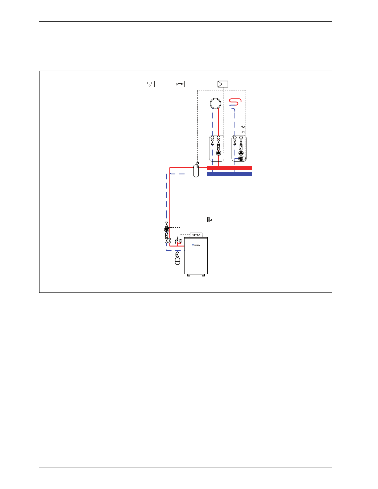
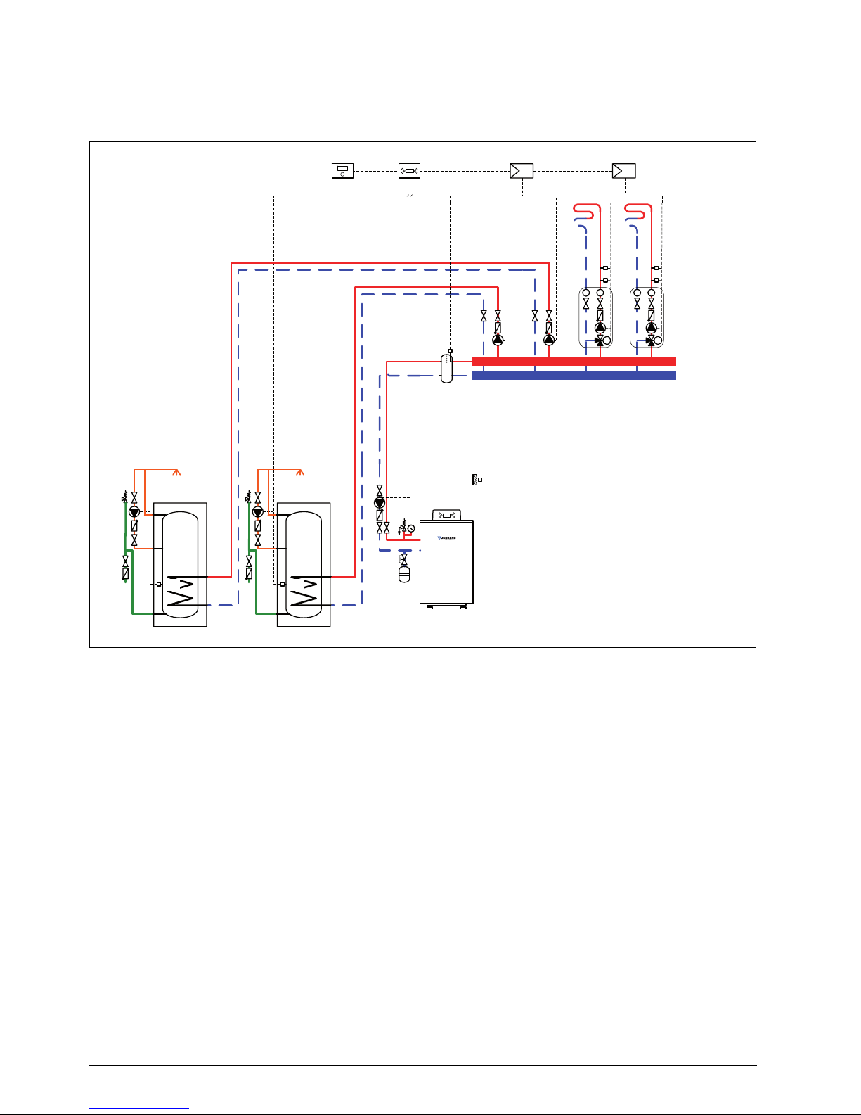
1 System schemes
1.1 System scheme 1: unmixed heating circuit, low loss header
Hydraulic scheme with controller (schematic diagram)
Fig. 1
AF Outside temperature sensor
CUx Boiler control unit
FW 100 Weather-compensated controller
HP Heating circuit pump (primary circuit)
IPM 1 Load switching module for one heating circuit
P Heating circuit pump (secondary circuit)
VF Common flow temperature sensor
1 Module position: on the heat source
3 Module position: on the wall
Heating system components
• Suprapur gas condensing boiler for balanced flue
operation
• One unmixed heating circuit
• Weather-compensated controller
Features
• Generally, we would recommend the installation of a
low loss header on site to ensure reliable transfer of
the required heating output.
• The FW ... weather-compensated controller is
preferred for its higher utilisation of condensing
technology.
• Determine the system water content and select a
corresponding expansion vessel (Æ page 39).
Function description
The unmixed heating circuit with low loss header is
regulated by an FW 100 weather-compensated
controller. This always requires the IPM 1 load switching
module. A 2-wire BUS system enables communication
between the boiler control unit, the controller and the
load switching module.
6 720 643 417-02.1O
IPM 1
AF
FW 100
3
CUx
1
VF
T
T
P
3
Suprapur
KBR 120-280
HP

System schemes
6 720 645 817 (2010/09)
5
The controller is suitable for wall mounting inside the
boiler room or in the living space. Installing it in the living
space enables room temperature hook-up.
Parts list
Model code Description Part no. Pce Price
Condensing boiler
KBR 120-3 A 23 Suprapur gas condensing boiler for natural gas 23 8 718 577 229
KBR 120-3 A 21 Suprapur gas condensing boiler for natural gas 21 8 718 577 285
KBR 160-3 A 23 Suprapur gas condensing boiler for natural gas 23 8 718 577 230
KBR 160-3 A 21 Suprapur gas condensing boiler for natural gas 21 8 718 577 286
KBR 200-3 A 23 Suprapur gas condensing boiler for natural gas 23 8 718 577 231
KBR 200-3 A 21 Suprapur gas condensing boiler for natural gas 21 8 718 577 287
KBR 240-3 A 23 Suprapur gas condensing boiler for natural gas 23 8 718 577 232
KBR 240-3 A 21 Suprapur gas condensing boiler for natural gas 21 8 718 577 288
KBR 280-3 A 23 Suprapur gas condensing boiler for natural gas 23 8 718 577 233
KBR 280-3 A 21 Suprapur gas condensing boiler for natural gas 21 8 718 577 289
Connection accessories
Boiler safety assembly for KBR 120-3 A 7 747 003 386
Boiler safety assembly for KBR 160 ... 280-3 A 7 747 003 387
Shut-off gate valve set for KBR 120-3 A 7 747 301 389
Shut-off gate valve set for KBR 160 ... 280-3 A 7 747 301 390
Dirt trap with fine sieve, DN 50, PN 6 80 950 210
Dirt trap with fine sieve, DN 65, PN 6 80 950 212
Dirt trap with standard sieve, DN 50, PN 6 80 950 110
Dirt trap with standard sieve, DN 65, PN 6 80 950 112
Gas tap R ¾ with TAE, for KBR 120-3 A 7 747 201 234
Gas tap R 1 ¼ with TAE, for KBR 160 ... 280-3 A 7 747 201 236
Compensator for gas connection, DN 25, for KBR 120-3 A 7 747 200 920
Compensator for gas connection, DN 32,
for KBR 160 ... 280-3 A
7 747 200 921
MAG ... (Æ page 72)
Controllers
FW 100 Weather-compensated controller 7 719 002 923
Controller accessories
FB 100 Remote control 7 719 002 907
IPM 1 Load switching module for one heating circuit 7 719 002 738
Other accessories
No. 1620 Condensate pump 80 695 080
No. 1605 Neutralising tank incl. neutralising granulate 8 718 576 749
No. 1606 Neutralising tank incl. condensate pump and neutralising
granulate
8 718 577 421
No. 1607 Neutralising granulate 7 115 120
Flue accessories (incl. boiler flue connection with test port)
(Æ chapter 11 from page 75)
Tab. 1
System schemes
6 720 645 817 (2010/09)
6
1.2 System scheme 2: unmixed underfloor heating circuit, low loss header
Hydraulic scheme with controller (schematic diagram)
Fig. 2
AF Outside temperature sensor
CUx Boiler control unit
FW 100 Weather-compensated controller
HP Heating circuit pump (primary circuit)
IPM 1 Load switching module for one heating circuit
P Heating circuit pump (secondary circuit)
TB Temperature limiter
VF Common flow temperature sensor
1 Module position: on the heat source
3 Module position: on the wall
Heating system components
• Suprapur gas condensing boiler for balanced flue
operation, without diaphragm expansion vessel
• One unmixed underfloor heating circuit
• Weather-compensated controller
Features
• Generally, we would recommend the installation of a
low loss header on site to ensure reliable transfer of
the required heating output.
• The FW ... weather-compensated controller is
preferred for its higher utilisation of condensing
technology.
• Determine the system water content and select a
corresponding expansion vessel (Æ page 39).
• Install a mechanical safety limiter (TB 1) in
accordance with the underfloor heating system
manufacturer's instructions.
Function description
The unmixed underfloor heating circuit with low loss
header is regulated by one FW 100 weathercompensated controller. This always requires the IPM 1
load switching module. A 2-wire BUS system enables
communication between the boiler control unit, the
controller and the load switching module.
The controller is suitable for wall mounting inside the
boiler room or in the living space. Installing it in the living
space enables room temperature hook-up.
1 MPI001 WF
3
AF
T
T
P
TB
CUx
1
VF
Suprapur
KBR 120-280
HP
3
6 720 643 417-01.1O

System schemes
6 720 645 817 (2010/09)
7
Parts list
Model code Description Part no. Pce Price
Condensing boiler
KBR 120-3 A 23 Suprapur gas condensing boiler for natural gas 23 8 718 577 229
KBR 120-3 A 21 Suprapur gas condensing boiler for natural gas 21 8 718 577 285
KBR 160-3 A 23 Suprapur gas condensing boiler for natural gas 23 8 718 577 230
KBR 160-3 A 21 Suprapur gas condensing boiler for natural gas 21 8 718 577 286
KBR 200-3 A 23 Suprapur gas condensing boiler for natural gas 23 8 718 577 231
KBR 200-3 A 21 Suprapur gas condensing boiler for natural gas 21 8 718 577 287
KBR 240-3 A 23 Suprapur gas condensing boiler for natural gas 23 8 718 577 232
KBR 240-3 A 21 Suprapur gas condensing boiler for natural gas 21 8 718 577 288
KBR 280-3 A 23 Suprapur gas condensing boiler for natural gas 23 8 718 577 233
KBR 280-3 A 21 Suprapur gas condensing boiler for natural gas 21 8 718 577 289
Connection accessories
Boiler safety assembly for KBR 120-3 A 7 747 003 386
Boiler safety assembly for KBR 160 ... 280-3 A 7 747 003 387
Shut-off gate valve set for KBR 120-3 A 7 747 301 389
Shut-off gate valve set for KBR 160 ... 280-3 A 7 747 301 390
Dirt trap with fine sieve, DN 50, PN 6 80 950 210
Dirt trap with fine sieve, DN 65, PN 6 80 950 212
Dirt trap with standard sieve, DN 50, PN 6 80 950 110
Dirt trap with standard sieve, DN 65, PN 6 80 950 112
Gas tap R ¾ with TAE, for KBR 120-3 A 7 747 201 234
Gas tap R 1 ¼ with TAE, for KBR 160 ... 280-3 A 7 747 201 236
Compensator for gas connection, DN 25, for KBR 120-3 A 7 747 200 920
Compensator for gas connection, DN 32,
for KBR 160 ... 280-3 A
7 747 200 921
MAG ... (Æ page 72)
Controllers
FW 100 Weather-compensated controller 7 719 002 923
Controller accessories
FB 100 Remote control 7 719 002 907
IPM 1 Load switching module for one heating circuit 7 719 002 738
TB 1 Temperature limiter 7 719 002 255
Other accessories
No. 1620 Condensate pump 80 695 080
No. 1605 Neutralising tank incl. neutralising granulate 8 718 576 749
No. 1606 Neutralising tank incl. condensate pump and neutralising
granulate
8 718 577 421
No. 1607 Neutralising granulate 7 115 120
Flue accessories (incl. boiler flue connection with test port)
(Æ chapter 11 from page 75)
Tab. 2
System schemes
6 720 645 817 (2010/09)
8
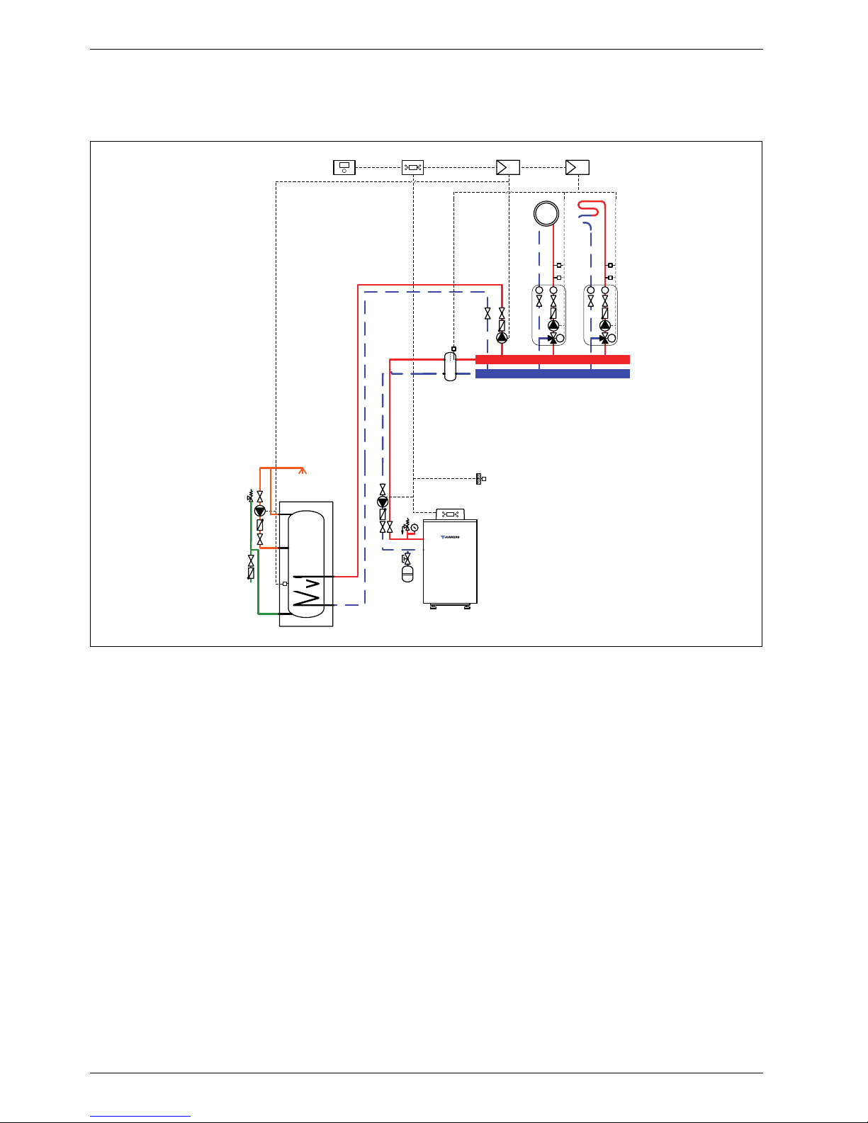
1.3 System scheme 3: mixed heating circuit, DHW circuit, low loss header
Hydraulic scheme with controller (schematic diagram)
Fig. 3
AF Outside temperature sensor
CUx Boiler control unit
FW 100 Weather-compensated controller
HP Heating circuit pump (primary circuit)
IPM 2 Load switching module for two heating circuits
LP Cylinder primary pump
M 3-way mixer
MF Mixer circuit temperature sensor
P Heating circuit pump (secondary circuit)
SF Cylinder temperature sensor
ST DHW cylinder
TB Temperature limiter
VF Common flow temperature sensor
ZP DHW circulation pump
1 Module position: on the heat source
3 Module position: on the wall
Heating system components
• Suprapur gas condensing boiler for balanced flue
operation
• One mixed heating circuit
• DHW cylinder
• Weather-compensated controller
Features
• Generally, we would recommend the installation of a
low loss header on site to ensure reliable transfer of
the required heating output.
• The FW ... weather-compensated controller is
preferred for its higher utilisation of condensing
technology.
• Determine the system water content and select a
corresponding expansion vessel (Æ page 39).
• Install a mechanical safety limiter (TB 1) in
accordance with the underfloor heating system
manufacturer's instructions.
• Install safety assembly to DIN 1988.
Function description
The mixed heating circuit with low loss header and
DHW heating are regulated by an FW 100 weathercompensated controller. This always requires the IPM 2
load switching module. A 2-wire BUS system enables
communication between the boiler control unit, the
controller and the load switching module.
6 720 643 417-03.1O
3
AF
3
CUx 2 MPI001 W
F
T
T
M
M
P
MF
TB
VF
LP
1
ZP
SF
ST ...
Suprapur
KBR 120-280
HP

System schemes
6 720 645 817 (2010/09)
9
The controller is suitable for wall mounting inside the
boiler room or in the living space. Installing it in the living
space enables room temperature hook-up.
Parts list
Model code Description Part no. Pce Price
Condensing boiler
KBR 120-3 A 23 Suprapur gas condensing boiler for natural gas 23 8 718 577 229
KBR 120-3 A 21 Suprapur gas condensing boiler for natural gas 21 8 718 577 285
KBR 160-3 A 23 Suprapur gas condensing boiler for natural gas 23 8 718 577 230
KBR 160-3 A 21 Suprapur gas condensing boiler for natural gas 21 8 718 577 286
KBR 200-3 A 23 Suprapur gas condensing boiler for natural gas 23 8 718 577 231
KBR 200-3 A 21 Suprapur gas condensing boiler for natural gas 21 8 718 577 287
KBR 240-3 A 23 Suprapur gas condensing boiler for natural gas 23 8 718 577 232
KBR 240-3 A 21 Suprapur gas condensing boiler for natural gas 21 8 718 577 288
KBR 280-3 A 23 Suprapur gas condensing boiler for natural gas 23 8 718 577 233
KBR 280-3 A 21 Suprapur gas condensing boiler for natural gas 21 8 718 577 289
Connection accessories
Boiler safety assembly for KBR 120-3 A 7 747 003 386
Boiler safety assembly for KBR 160 ... 280-3 A 7 747 003 387
Shut-off gate valve set for KBR 120-3 A 7 747 301 389
Shut-off gate valve set for KBR 160 ... 280-3 A 7 747 301 390
Dirt trap with fine sieve, DN 50, PN 6 80 950 210
Dirt trap with fine sieve, DN 65, PN 6 80 950 212
Dirt trap with standard sieve, DN 50, PN 6 80 950 110
Dirt trap with standard sieve, DN 65, PN 6 80 950 112
Gas tap R ¾ with TAE, for KBR 120-3 A 7 747 201 234
Gas tap R 1 ¼ with TAE, for KBR 160 ... 280-3 A 7 747 201 236
Compensator for gas connection, DN 25, for KBR 120-3 A 7 747 200 920
Compensator for gas connection, DN 32,
for KBR 160 ... 280-3 A
7 747 200 921
MAG ... (Æ page 72)
DHW cylinder
(Æ chapter 9 from page 60)
Controllers
FW 100 Weather-compensated controller 7 719 002 923
Controller accessories
FB 100 Remote control 7 719 002 907
IPM 2 Load switching module for two heating circuits 7 719 002 739
TB 1 Temperature limiter 7 719 002 255
Other accessories
No. 1620 Condensate pump 80 695 080
No. 1605 Neutralising tank incl. neutralising granulate 8 718 576 749
No. 1606 Neutralising tank incl. condensate pump and neutralising
granulate
8 718 577 421
No. 1607 Neutralising granulate 7 115 120
Flue accessories (incl. boiler flue connection with test port)
(Æ chapter 11 from page 75)
Tab. 3
System schemes
6 720 645 817 (2010/09)
10
1.4 System scheme 4: one unmixed heating circuit, one mixed heating circuit, low loss
header
Hydraulic scheme with controller (schematic diagram)
Fig. 4
AF Outside temperature sensor
CUx Boiler control unit
FW 200 Weather-compensated controller
HP Heating circuit pump (primary circuit)
IPM 2 Load switching module for two heating circuits
M 3-way mixer
MF Mixer circuit temperature sensor
P
1,2
Heating circuit pump (secondary circuit)
TB Temperature limiter
VF Common flow temperature sensor
1 Module position: on the heat source
3 Module position: on the wall
Heating system components
• Suprapur gas condensing boiler for balanced flue
operation, without diaphragm expansion vessel
• One unmixed heating circuit
• One mixed heating circuit
• Weather-compensated controller
Features
• Generally, we would recommend the installation of a
low loss header on site to ensure reliable transfer of
the required heating output.
• The FW ... weather-compensated controller is
preferred for its higher utilisation of condensing
technology.
• Determine the system water content and select a
corresponding expansion vessel (Æ page 39).
• Install a mechanical safety limiter (TB 1) in
accordance with the underfloor heating system
manufacturer's instructions.
Function description
The heating circuits are regulated by an FW 200
weather-compensated controller. This always requires
the IPM 2 load switching module. A 2-wire BUS system
enables communication between the boiler control unit,
the controller and the load switching module.
6 720 643 417-04.1O
1
AF
3
T
T
P1
T
T
M
M
P2
MF
TB
IPM 2
CUx
FW 200
3
VF
Suprapur
KBR 120-280
HP

System schemes
6 720 645 817 (2010/09)
11
The controller is suitable for wall mounting inside the
boiler room or in the living space. Installing it in the living
space enables room temperature hook-up.
Parts list
Model code Description Part no. Pce Price
Condensing boiler
KBR 120-3 A 23 Suprapur gas condensing boiler for natural gas 23 8 718 577 229
KBR 120-3 A 21 Suprapur gas condensing boiler for natural gas 21 8 718 577 285
KBR 160-3 A 23 Suprapur gas condensing boiler for natural gas 23 8 718 577 230
KBR 160-3 A 21 Suprapur gas condensing boiler for natural gas 21 8 718 577 286
KBR 200-3 A 23 Suprapur gas condensing boiler for natural gas 23 8 718 577 231
KBR 200-3 A 21 Suprapur gas condensing boiler for natural gas 21 8 718 577 287
KBR 240-3 A 23 Suprapur gas condensing boiler for natural gas 23 8 718 577 232
KBR 240-3 A 21 Suprapur gas condensing boiler for natural gas 21 8 718 577 288
KBR 280-3 A 23 Suprapur gas condensing boiler for natural gas 23 8 718 577 233
KBR 280-3 A 21 Suprapur gas condensing boiler for natural gas 21 8 718 577 289
Connection accessories
Boiler safety assembly for KBR 120-3 A 7 747 003 386
Boiler safety assembly for KBR 160 ... 280-3 A 7 747 003 387
Shut-off gate valve set for KBR 120-3 A 7 747 301 389
Shut-off gate valve set for KBR 160 ... 280-3 A 7 747 301 390
Dirt trap with fine sieve, DN 50, PN 6 80 950 210
Dirt trap with fine sieve, DN 65, PN 6 80 950 212
Dirt trap with standard sieve, DN 50, PN 6 80 950 110
Dirt trap with standard sieve, DN 65, PN 6 80 950 112
Gas tap R ¾ with TAE, for KBR 120-3 A 7 747 201 234
Gas tap R 1 ¼ with TAE, for KBR 160 ... 280-3 A 7 747 201 236
Compensator for gas connection, DN 25, for KBR 120-3 A 7 747 200 920
Compensator for gas connection, DN 32,
for KBR 160 ... 280-3 A
7 747 200 921
MAG ... (Æ page 72)
Controllers
FW 200 Weather-compensated controller 7 719 002 507
Controller accessories
FB 100 Remote control 7 719 002 907
IPM 2 Load switching module for two heating circuits 7 719 002 739
TB 1 Temperature limiter 7 719 002 255
Other accessories
No. 1620 Condensate pump 80 695 080
No. 1605 Neutralising tank incl. neutralising granulate 8 718 576 749
No. 1606 Neutralising tank incl. condensate pump and neutralising
granulate
8 718 577 421
No. 1607 Neutralising granulate 7 115 120
Flue accessories (incl. boiler flue connection with test port)
(Æ chapter 11 from page 75)
Tab. 4
System schemes
6 720 645 817 (2010/09)
12
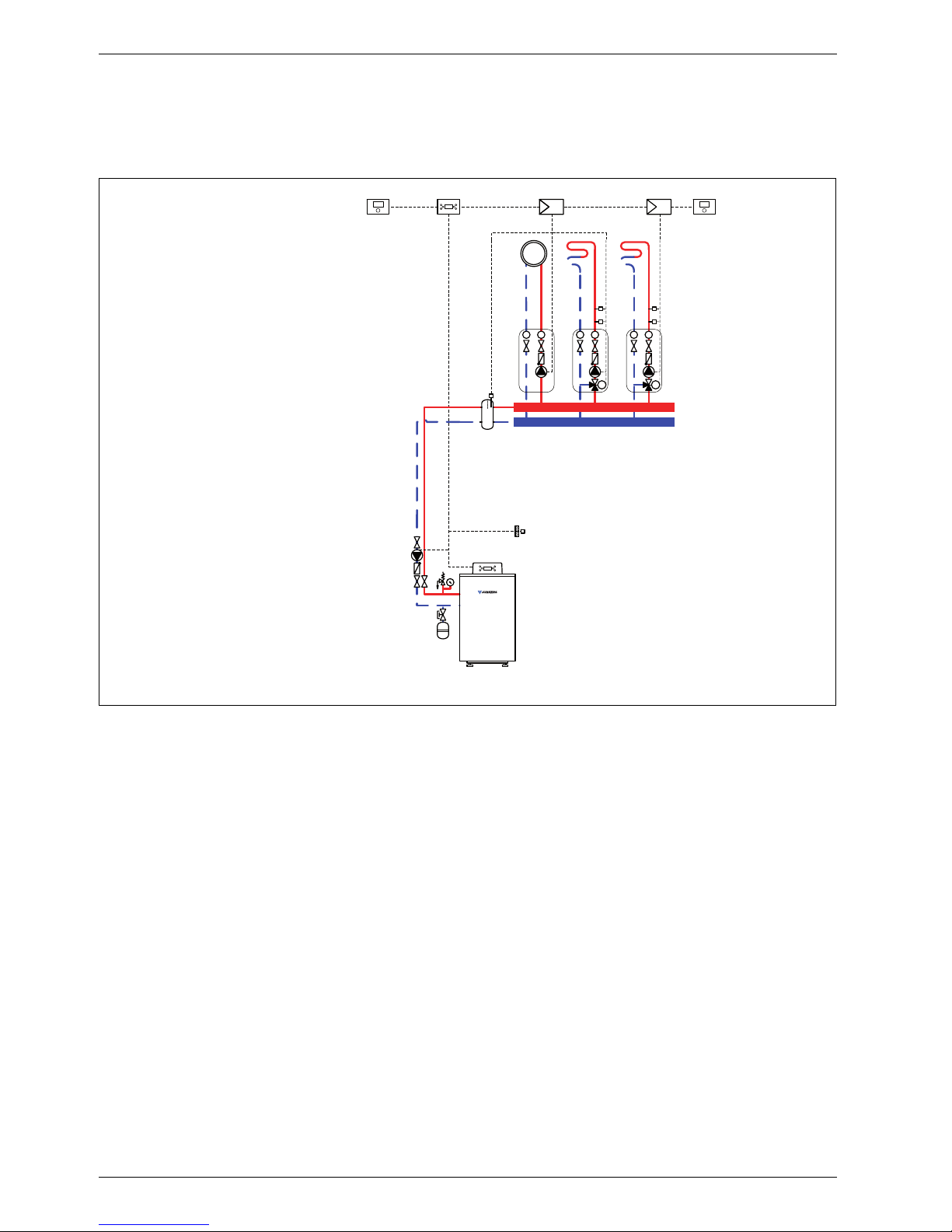
1.5 System scheme 5: two mixed heating circuits, one DHW circuit, low loss header
Hydraulic scheme with controller (schematic diagram)
Fig. 5
AF Outside temperature sensor
CUx Boiler control unit
FW 200 Weather-compensated controller
HP Heating circuit pump (primary circuit)
IPM 1 Load switching module for one heating circuit
IPM 2 Load switching module for two heating circuits
LP Cylinder primary pump
M
1,2
3-way mixer
MF
1,2
Mixer circuit temperature sensor
P
1,2
Heating circuit pump (secondary circuit)
SF Cylinder temperature sensor
ST ... DHW cylinder
TB
1,2
Temperature limiter
VF Common flow temperature sensor
ZP DHW circulation pump
1 Module position: on the heat source
3 Module position: on the wall
Heating system components
• Suprapur gas condensing boiler for balanced flue
operation
• Two mixed heating circuits
• DHW cylinder
• Weather-compensated controller
Features
• Generally, we would recommend the installation of a
low loss header on site to ensure reliable transfer of
the required heating output.
• The FW ... weather-compensated controller is
preferred for its higher utilisation of condensing
technology.
• Determine the system water content and select a
corresponding expansion vessel (Æ page 39).
• Install a mechanical safety limiter (TB 1) in
accordance with the underfloor heating system
manufacturer's instructions.
• Install safety assembly to DIN 1988.
Function description
The heating circuits are regulated by an FW 200
weather-compensated controller. This always requires
the IPM 1 and IPM 2 load switching modules. A 2-wire
BUS system enables communication between the boiler
control unit, the controller and the load switching
modules.
6 720 643 417-06.1O
AF
T
T
M
M2
P2
MF2
TB2
LP
VF
1
3
IPM 1
CUx
FW 200
3
3
IPM 2
ZP
SF
ST ...
Suprapur
KBR 120-280
HP
T
T
M
M1
P1
MF1
TB1

System schemes
6 720 645 817 (2010/09)
13
The controller is suitable for wall mounting inside the
boiler room or in the living space. Installing it in the living
space enables room temperature hook-up.
Parts list
Model code Description Part no. Pce Price
Condensing boiler
KBR 120-3 A 23 Suprapur gas condensing boiler for natural gas 23 8 718 577 229
KBR 120-3 A 21 Suprapur gas condensing boiler for natural gas 21 8 718 577 285
KBR 160-3 A 23 Suprapur gas condensing boiler for natural gas 23 8 718 577 230
KBR 160-3 A 21 Suprapur gas condensing boiler for natural gas 21 8 718 577 286
KBR 200-3 A 23 Suprapur gas condensing boiler for natural gas 23 8 718 577 231
KBR 200-3 A 21 Suprapur gas condensing boiler for natural gas 21 8 718 577 287
KBR 240-3 A 23 Suprapur gas condensing boiler for natural gas 23 8 718 577 232
KBR 240-3 A 21 Suprapur gas condensing boiler for natural gas 21 8 718 577 288
KBR 280-3 A 23 Suprapur gas condensing boiler for natural gas 23 8 718 577 233
KBR 280-3 A 21 Suprapur gas condensing boiler for natural gas 21 8 718 577 289
Connection accessories
Boiler safety assembly for KBR 120-3 A 7 747 003 386
Boiler safety assembly for KBR 160 ... 280-3 A 7 747 003 387
Shut-off gate valve set for KBR 120-3 A 7 747 301 389
Shut-off gate valve set for KBR 160 ... 280-3 A 7 747 301 390
Dirt trap with fine sieve, DN 50, PN 6 80 950 210
Dirt trap with fine sieve, DN 65, PN 6 80 950 212
Dirt trap with standard sieve, DN 50, PN 6 80 950 110
Dirt trap with standard sieve, DN 65, PN 6 80 950 112
Gas tap R ¾ with TAE, for KBR 120-3 A 7 747 201 234
Gas tap R 1 ¼ with TAE, for KBR 160 ... 280-3 A 7 747 201 236
Compensator for gas connection, DN 25, for KBR 120-3 A 7 747 200 920
Compensator for gas connection, DN 32,
for KBR 160 ... 280-3 A
7 747 200 921
MAG ... (Æ page 72)
DHW cylinder
(Æ chapter 9 from page 60)
Controllers
FW 200 Weather-compensated controller 7 719 002 507
Controller accessories
FB 100 Remote control 7 719 002 907
IPM 1 Load switching module for one heating circuit 7 719 002 738
IPM 2 Load switching module for two heating circuits 7 719 002 739
TB 1 Temperature limiter 7 719 002 255
Other accessories
No. 1620 Condensate pump 80 695 080
No. 1605 Neutralising tank incl. neutralising granulate 8 718 576 749
No. 1606 Neutralising tank incl. condensate pump and neutralising
granulate
8 718 577 421
No. 1607 Neutralising granulate 7 115 120
Flue accessories (incl. boiler flue connection with test port)
(Æ chapter 11 from page 75)
Tab. 5
System schemes
6 720 645 817 (2010/09)
14
1.6 System scheme 6: one unmixed heating circuit, two mixed heating circuits, low loss
header
Hydraulic scheme with controller (schematic diagram)
Fig. 6
AF Outside temperature sensor
CUx Boiler control unit
FB 100 Remote control
FW 200 Weather-compensated controller
HP Heating circuit pump (primary circuit)
IPM 1 Load switching module for one heating circuit
IPM 2 Load switching module for two heating circuits
M
2,3
3-way mixer
MF
2,3
Mixer circuit temperature sensor
P
1,3
Heating circuit pump (secondary circuit)
TB Temperature limiter
VF Common flow temperature sensor
1 Module position: on the heat source
3 Module position: on the wall
Heating system components
• Suprapur gas condensing boiler for balanced flue
operation
• One unmixed heating circuit
• Two mixed heating circuits
• Weather-compensated controller
Features
• Generally, we would recommend the installation of a
low loss header on site to ensure reliable transfer of
the required heating output.
• The FW ... weather-compensated controller is
preferred for its higher utilisation of condensing
technology.
• Determine the system water content and select a
corresponding expansion vessel (Æ page 39).
• Install a mechanical safety limiter (TB 1) in
accordance with the underfloor heating system
manufacturer's instructions.
• Install safety assembly to DIN 1988.
Function description
The heating circuits are regulated by an FW 200
weather-compensated controller. This always requires
the IPM 1 and IPM 2 load switching modules. A 2-wire
BUS system enables communication between the boiler
control unit, the controller and the load switching
modules.
6 720 643 417-07.1O
IPM 2 IPM 1AFFB 100
VK
T
T
P1
T
T
M
M2
P2
MF2
TB
T
T
M
M3
P3
MF3
TB
1
CUx
FW 200
3
333
Suprapur
KBR 120-280
HP

System schemes
6 720 645 817 (2010/09)
15
The controller is suitable for wall mounting inside the
boiler room or in the living space. Installing it in the living
space enables room temperature hook-up.
A FB 100 remote control is required for the third heating
circuit.
Parts list
Model code Description Part no. Pce Price
Condensing boiler
KBR 120-3 A 23 Suprapur gas condensing boiler for natural gas 23 8 718 577 229
KBR 120-3 A 21 Suprapur gas condensing boiler for natural gas 21 8 718 577 285
KBR 160-3 A 23 Suprapur gas condensing boiler for natural gas 23 8 718 577 230
KBR 160-3 A 21 Suprapur gas condensing boiler for natural gas 21 8 718 577 286
KBR 200-3 A 23 Suprapur gas condensing boiler for natural gas 23 8 718 577 231
KBR 200-3 A 21 Suprapur gas condensing boiler for natural gas 21 8 718 577 287
KBR 240-3 A 23 Suprapur gas condensing boiler for natural gas 23 8 718 577 232
KBR 240-3 A 21 Suprapur gas condensing boiler for natural gas 21 8 718 577 288
KBR 280-3 A 23 Suprapur gas condensing boiler for natural gas 23 8 718 577 233
KBR 280-3 A 21 Suprapur gas condensing boiler for natural gas 21 8 718 577 289
Connection accessories
Boiler safety assembly for KBR 120-3 A 7 747 003 386
Boiler safety assembly for KBR 160 ... 280-3 A 7 747 003 387
Shut-off gate valve set for KBR 120-3 A 7 747 301 389
Shut-off gate valve set for KBR 160 ... 280-3 A 7 747 301 390
Dirt trap with fine sieve, DN 50, PN 6 80 950 210
Dirt trap with fine sieve, DN 65, PN 6 80 950 212
Dirt trap with standard sieve, DN 50, PN 6 80 950 110
Dirt trap with standard sieve, DN 65, PN 6 80 950 112
Gas tap R ¾ with TAE, for KBR 120-3 A 7 747 201 234
Gas tap R 1 ¼ with TAE, for KBR 160 ... 280-3 A 7 747 201 236
Compensator for gas connection, DN 25, for KBR 120-3 A 7 747 200 920
Compensator for gas connection, DN 32,
for KBR 160 ... 280-3 A
7 747 200 921
MAG ... (Æ page 72)
Controllers
FW 200 Weather-compensated controller 7 719 002 507
Controller accessories
FB 100 Remote control 7 719 002 907
IPM 1 Load switching module for one heating circuit 7 719 002 738
IPM 2 Load switching module for two heating circuits 7 719 002 739
TB 1 Temperature limiter 7 719 002 255
Other accessories
No. 1620 Condensate pump 80 695 080
No. 1605 Neutralising tank incl. neutralising granulate 8 718 576 749
No. 1606 Neutralising tank incl. condensate pump and neutralising
granulate
8 718 577 421
No. 1607 Neutralising granulate 7 115 120
Flue accessories (incl. boiler flue connection with test port)
(Æ chapter 11 from page 75)
Tab. 6
System schemes
6 720 645 817 (2010/09)
16
1.7 System scheme 7: one unmixed heating circuit, three mixed heating circuits, low loss
header
Hydraulic scheme with controller (schematic diagram)
Fig. 7
AF Outside temperature sensor
CUx Boiler control unit
FB 100 Remote control
FW 200 Weather-compensated controller
HP Heating circuit pump (primary circuit)
IPM 2 Load switching module for two heating circuits
M
2,4
3-way mixer
MF
2,4
Mixer circuit temperature sensor
P
1,4
Heating circuit pump (secondary circuit)
TB Temperature limiter
VF Common flow temperature sensor
1 Module position: on the heat source
3 Module position: on the wall
Heating system components
• Suprapur gas condensing boiler for balanced flue
operation, without diaphragm expansion vessel
• One unmixed heating circuit
• Three mixed heating circuits
• Weather-compensated controller
Features
• Generally, we would recommend the installation of a
low loss header on site to ensure reliable transfer of
the required heating output.
• The FW ... weather-compensated controller is
preferred for its higher utilisation of condensing
technology.
• Determine the system water content and select a
corresponding expansion vessel (Æ page 39).
• Install a mechanical safety limiter (TB 1) in
accordance with the underfloor heating system
manufacturer's instructions.
Function description
The heating circuits are regulated by an FW 200
weather-compensated controller. This always requires
two IPM 2 load switching modules. A 2-wire BUS system
enables communication between the boiler control unit,
the controller and the load switching modules.
6 720 643 417-08.1O
IPM 2 IPM 2
AF
FB 100 FB 100
1
CUx
FW 200
333
3
3
VF
T
T
P1
T
T
M
M2
P2
MF2
TB
T
T
M
M3
P3
MF3
TB
T
T
M
M4
P4
MF4
TB
Suprapur
KBR 120-280
HP

System schemes
6 720 645 817 (2010/09)
17
The controller is suitable for wall mounting inside the
boiler room or in the living space. Installing it in the living
space enables room temperature hook-up.
One FB 100 remote control is required for each of the
third and fourth heating circuits.
Parts list
Model code Description Part no. Pce Price
Condensing boiler
KBR 120-3 A 23 Suprapur gas condensing boiler for natural gas 23 8 718 577 229
KBR 120-3 A 21 Suprapur gas condensing boiler for natural gas 21 8 718 577 285
KBR 160-3 A 23 Suprapur gas condensing boiler for natural gas 23 8 718 577 230
KBR 160-3 A 21 Suprapur gas condensing boiler for natural gas 21 8 718 577 286
KBR 200-3 A 23 Suprapur gas condensing boiler for natural gas 23 8 718 577 231
KBR 200-3 A 21 Suprapur gas condensing boiler for natural gas 21 8 718 577 287
KBR 240-3 A 23 Suprapur gas condensing boiler for natural gas 23 8 718 577 232
KBR 240-3 A 21 Suprapur gas condensing boiler for natural gas 21 8 718 577 288
KBR 280-3 A 23 Suprapur gas condensing boiler for natural gas 23 8 718 577 233
KBR 280-3 A 21 Suprapur gas condensing boiler for natural gas 21 8 718 577 289
Connection accessories
Boiler safety assembly for KBR 120-3 A 7 747 003 386
Boiler safety assembly for KBR 160 ... 280-3 A 7 747 003 387
Shut-off gate valve set for KBR 120-3 A 7 747 301 389
Shut-off gate valve set for KBR 160 ... 280-3 A 7 747 301 390
Dirt trap with fine sieve, DN 50, PN 6 80 950 210
Dirt trap with fine sieve, DN 65, PN 6 80 950 212
Dirt trap with standard sieve, DN 50, PN 6 80 950 110
Dirt trap with standard sieve, DN 65, PN 6 80 950 112
Gas tap R ¾ with TAE, for KBR 120-3 A 7 747 201 234
Gas tap R 1 ¼ with TAE, for KBR 160 ... 280-3 A 7 747 201 236
Compensator for gas connection, DN 25, for KBR 120-3 A 7 747 200 920
Compensator for gas connection, DN 32,
for KBR 160 ... 280-3 A
7 747 200 921
MAG ... (Æ page 72)
Controllers
FW 200 Weather-compensated controller 7 719 002 507
Controller accessories
FB 100 Remote control 7 719 002 907
IPM 2 Load switching module for two heating circuits 7 719 002 739
TB 1 Temperature limiter 7 719 002 255
Other accessories
No. 1620 Condensate pump 80 695 080
No. 1605 Neutralising tank incl. neutralising granulate 8 718 576 749
No. 1606 Neutralising tank incl. condensate pump and neutralising
granulate
8 718 577 421
No. 1607 Neutralising granulate 7 115 120
Flue accessories (incl. boiler flue connection with test port)
(Æ chapter 11 from page 75)
Tab. 7
System schemes
6 720 645 817 (2010/09)
18
1.8 System scheme 8: two mixed heating circuits, two DHW circuits, low loss header
Hydraulic scheme with controller (schematic diagram)
Fig. 8
AF Outside temperature sensor
CUx Boiler control unit
FW 500 Weather-compensated controller
HP Heating circuit pump (primary circuit)
IPM 2 Load switching module for two heating circuits
LP
1,2
Cylinder primary pump
M
1,2
3-way mixer
MF
1,2
Mixer circuit temperature sensor
P
1,2
Heating circuit pump (secondary circuit)
SF Cylinder temperature sensor
ST ... DHW cylinder
TB Temperature limiter
VF Common flow temperature sensor
ZP DHW circulation pump
1 Module position: on the heat source
3 Module position: on the wall
Heating system components
• Suprapur gas condensing boiler for balanced flue
operation
• Two mixed heating circuits
• Two DHW circuits
• Weather-compensated controller
Features
• Generally, we would recommend the installation of a
low loss header on site to ensure reliable transfer of
the required heating output.
• The FW ... weather-compensated controller is
preferred for its higher utilisation of condensing
technology.
• Determine the system water content and select a
corresponding expansion vessel (Æ page 39).
• Install a mechanical safety limiter (TB 1) in
accordance with the underfloor heating system
manufacturer's instructions.
• Install safety assembly to DIN 1988.
6 720 643 417-09.1O
IPM 2
AF
LP1 LP2
TT
M
M1
P1
MF1
TB
TT
M
M2
P2
MF2
TB
IPM 2
3
3
VF
1
CUx
FW 500
3
Suprapur
KBR 120-280
HP
ZP
SF
ST ...
ZP
SF
ST ...

System schemes
6 720 645 817 (2010/09)
19
Function description
The heating circuits are regulated by an FW 500
weather-compensated controller. This always requires
two IPM 2 load switching modules. A 2-wire BUS system
enables communication between the boiler control unit,
the controller and the load switching modules.
The controller is suitable for wall mounting inside the
boiler room or in the living space. Installing it in the living
space enables room temperature hook-up.
Parts list
Model code Description Part no. Pce Price
Condensing boiler
KBR 120-3 A 23 Suprapur gas condensing boiler for natural gas 23 8 718 577 229
KBR 120-3 A 21 Suprapur gas condensing boiler for natural gas 21 8 718 577 285
KBR 160-3 A 23 Suprapur gas condensing boiler for natural gas 23 8 718 577 230
KBR 160-3 A 21 Suprapur gas condensing boiler for natural gas 21 8 718 577 286
KBR 200-3 A 23 Suprapur gas condensing boiler for natural gas 23 8 718 577 231
KBR 200-3 A 21 Suprapur gas condensing boiler for natural gas 21 8 718 577 287
KBR 240-3 A 23 Suprapur gas condensing boiler for natural gas 23 8 718 577 232
KBR 240-3 A 21 Suprapur gas condensing boiler for natural gas 21 8 718 577 288
KBR 280-3 A 23 Suprapur gas condensing boiler for natural gas 23 8 718 577 233
KBR 280-3 A 21 Suprapur gas condensing boiler for natural gas 21 8 718 577 289
Connection accessories
Boiler safety assembly for KBR 120-3 A 7 747 003 386
Boiler safety assembly for KBR 160 ... 280-3 A 7 747 003 387
Shut-off gate valve set for KBR 120-3 A 7 747 301 389
Shut-off gate valve set for KBR 160 ... 280-3 A 7 747 301 390
Dirt trap with fine sieve, DN 50, PN 6 80 950 210
Dirt trap with fine sieve, DN 65, PN 6 80 950 212
Dirt trap with standard sieve, DN 50, PN 6 80 950 110
Dirt trap with standard sieve, DN 65, PN 6 80 950 112
Gas tap R ¾ with TAE, for KBR 120-3 A 7 747 201 234
Gas tap R 1 ¼ with TAE, for KBR 160 ... 280-3 A 7 747 201 236
Compensator for gas connection, DN 25, for KBR 120-3 A 7 747 200 920
Compensator for gas connection, DN 32,
for KBR 160 ... 280-3 A
7 747 200 921
MAG ... (Æ page 72)
DHW cylinder
(Æ chapter 9 from page 60)
Controllers
FW 500 Weather-compensated controller 7 719 002 966
Controller accessories
FB 100 Remote control 7 719 002 907
IPM 2 Load switching module for two heating circuits 7 719 002 739
TB 1 Temperature limiter 7 719 002 255
Other accessories
No. 1620 Condensate pump 80 695 080
No. 1605 Neutralising tank incl. neutralising granulate 8 718 576 749
No. 1606 Neutralising tank incl. condensate pump and neutralising
granulate
8 718 577 421
No. 1607 Neutralising granulate 7 115 120
Flue accessories (incl. boiler flue connection with test port)
(Æ chapter 11 from page 75)
Tab. 8
System schemes
6 720 645 817 (2010/09)
20
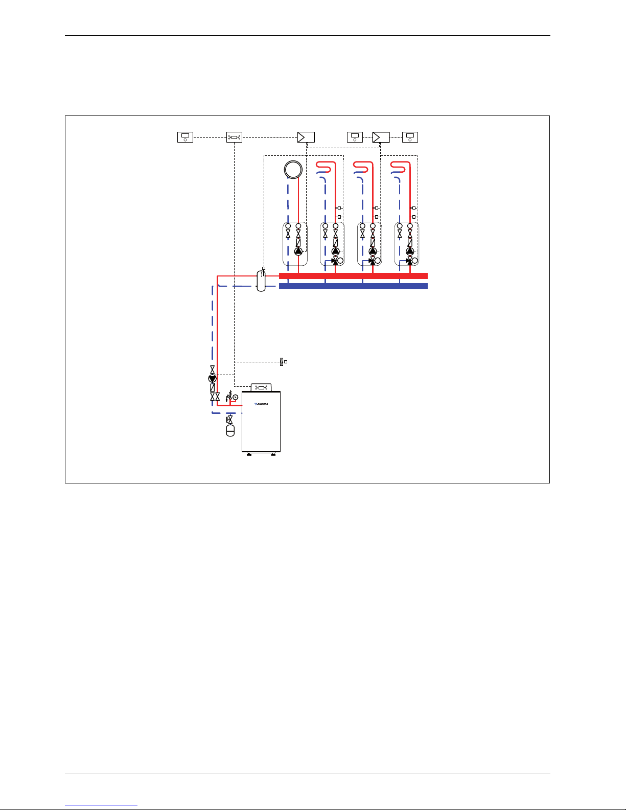
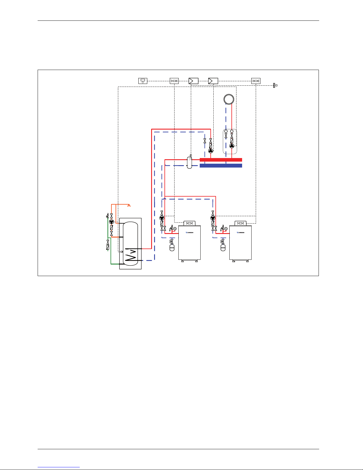
1.9 System scheme 9: one unmixed heating circuit, one DHW circuit, low loss header,
cascade
Hydraulic scheme with controller (schematic diagram)
Fig. 9
AF Outside temperature sensor
CUx Boiler control unit
FW 200 Weather-compensated controller
HP Heating circuit pump (primary circuit)
ICM Cascade switching module
IPM 2 Load switching module for two heating circuits
LP Cylinder primary pump
P Heating circuit pump (secondary circuit)
SF Cylinder temperature sensor
ST ... DHW cylinder
VF Common flow temperature sensor
ZP DHW circulation pump
1 Module position: on the heat source
3 Module position: on the wall
Heating system components
• Two Suprapur gas condensing boilers for balanced
flue operation
• One unmixed heating circuit
• One DHW circuit
• Weather-compensated controller
• Cascade switching module
Features
• The on-site installation of a low loss header is
required to ensure the reliable transfer of the
required heating output.
• The FW ... weather-compensated controller is
preferred for its higher utilisation of condensing
technology.
• Determine the system water content and select a
corresponding expansion vessel (Æ page 39).
• Install safety assembly to DIN 1988.
Function description
The boiler cascade, the unmixed heating circuit and the
DHW circuit are regulated by an FW 200 weathercompensated controller. This always requires two IPM 2
load switching modules. A 2-wire BUS system enables
communication between the boiler control units, the
controller and the load switching modules.
6 720 643 417-10.1O
3
IPM 2
AF
3
FW 200 ICM
3
CUx
1
ZP
SF
ST ...
LP
VF
TT
P
HP
Suprapur
MKB 240-560
HP
CUx
1
System schemes
6 720 645 817 (2010/09)
21
The controller is suitable for wall mounting inside the
boiler room or in the living space. Installing it in the living
space enables room temperature hook-up.
Parts list
Model code Description Part no. Pce Price
Condensing boiler
KBR 120-3 A 23 Suprapur gas condensing boiler for natural gas 23 8 718 577 229
KBR 120-3 A 21 Suprapur gas condensing boiler for natural gas 21 8 718 577 285
KBR 160-3 A 23 Suprapur gas condensing boiler for natural gas 23 8 718 577 230
KBR 160-3 A 21 Suprapur gas condensing boiler for natural gas 21 8 718 577 286
KBR 200-3 A 23 Suprapur gas condensing boiler for natural gas 23 8 718 577 231
KBR 200-3 A 21 Suprapur gas condensing boiler for natural gas 21 8 718 577 287
KBR 240-3 A 23 Suprapur gas condensing boiler for natural gas 23 8 718 577 232
KBR 240-3 A 21 Suprapur gas condensing boiler for natural gas 21 8 718 577 288
KBR 280-3 A 23 Suprapur gas condensing boiler for natural gas 23 8 718 577 233
KBR 280-3 A 21 Suprapur gas condensing boiler for natural gas 21 8 718 577 289
Connection accessories
Boiler safety assembly for KBR 120-3 A 7 747 003 386
Boiler safety assembly for KBR 160 ... 280-3 A 7 747 003 387
Shut-off gate valve set for KBR 120-3 A 7 747 301 389
Shut-off gate valve set for KBR 160 ... 280-3 A 7 747 301 390
Dirt trap with fine sieve, DN 50, PN 6 80 950 210
Dirt trap with fine sieve, DN 65, PN 6 80 950 212
Dirt trap with standard sieve, DN 50, PN 6 80 950 110
Dirt trap with standard sieve, DN 65, PN 6 80 950 112
Gas tap R ¾ with TAE, for KBR 120-3 A 7 747 201 234
Gas tap R 1 ¼ with TAE, for KBR 160 ... 280-3 A 7 747 201 236
Compensator for gas connection, DN 25, for KBR 120-3 A 7 747 200 920
Compensator for gas connection, DN 32,
for KBR 160 ... 280-3 A
7 747 200 921
MAG ... (Æ page 72)
DHW cylinder
(Æ chapter 9 from page 60)
Controllers
FW 200 Weather-compensated controller 7 719 002 507
ICM Cascade switching module 7 719 002 949
Controller accessories
FB 100 Remote control 7 719 002 907
IPM 2 Load switching module for two heating circuits 7 719 002 739
TB 1 Temperature limiter 7 719 002 255
Other accessories
No. 1620 Condensate pump 80 695 080
No. 1605 Neutralising tank incl. neutralising granulate 8 718 576 749
No. 1606 Neutralising tank incl. condensate pump and neutralising
granulate
8 718 577 421
No. 1607 Neutralising granulate 7 115 120
Flue accessories (incl. boiler flue connection with test port)
(Æ chapter 11 from page 75)
Tab. 9
Specification
6 720 645 817 (2010/09)
22
2 Specification
2.1 Appliance parameters
2.1.1 Single appliance Suprapur KBR ...
Boiler size (output in kW) Unit KBR 120-3 A KBR 160-3 A KBR 200-3 A KBR 200-3 A KBR 240-3 A
Number of sections – 4 5 6 7 8
Rated output full load/partial load
temperature pair 50/30 °C
kW 120/31 160/42 200/62 240/75 280/87
Rated output full load/partial load
temperature pair 80/60 °C
kW 113/28 150/38 187/56.2 225/67.6 263/79.2
Rated heat input full load/partial load kW 115.9/29 155/38.8 193/57.9 232/69.6 271/81.3
Flue gas mass flow rate full load/partial
load temperature pair 50/30 °C
g/s 53.8/10.1 70.2/12.9 87.8/21.5 106.0/23.0 125.9/28.4
Flue gas mass flow rate full load/partial
load temperature pair 80/60 °C
g/s 53.7/11.1 70.2/14.1 89.3/21.6 107.4/25.0 125.4/33.4
CO2 content with natural gas full load/
partial load
% 9.1/9.3
Minimum flue gas temperature full load/
partial load temperature pair 50/30 °C
°C 56/32 54/31 55/34 55/33 57/34
Minimum flue gas temperature full load/
partial load temperature pair 80/60 °C
°C < 75/57 < 75/56 < 75/59 < 75/58 < 75/59
Available draught, flue system Pa 100
Type (acc. to DVGW regulations) –
B23, B
23P
, C53, (C63), C
93
open flue and balanced flue operation
Gas
Fan – G1G 170
Gas valve –
Honeywell Kromschröder
VR 4615V VR 415VE CG 20 CG 25 CG 25
Gas restrictor diameter:
Natural gas H (G20),
Wobbe index 14.9 kWh/m
3
Natural gas L (Germany),
Wobbe index 12.8 kWh/m
3
mm
mm
15.7
15.0
Gas
restrictor
not fitted
14.2
14.2
13.6
13.6
12.6
12.6
Heating water circuit
Boiler water capacity l 16 20 24 27 30
Pressure drop on heating water side mbar Æ Fig. 14, page 29
Maximum flow temperature °C 85
Safety temp. for high limit safety cut-out °C 100
Permissible operating pressure bar 4
Electrical data
IP rating – IPX0D
Power supply V/Hz 230/50
Power consumption full load/partial load W 150/40 190/45 230/50 270/50 330/50
Appliance dimensions and weight
Handling dimensions
Width × Depth × Height
mm
851 × 612
× 1400
1059 × 612
× 1400
1059 × 612
×1400
1267 × 612
× 1400
1267 × 612
× 1400
Weight kg 205 240 265 300 330
Tab. 10 Specification
Specification
6 720 645 817 (2010/09)
23
2.1.2 Factory-prepared cascade Suprapur MKB ...
Boiler size (output in kW) Unit
MKB
240-3 A
MKB
320-3 A
MKB
400-3 A
MKB
480-3 A
MKB
560-3 A
Number of sections – 8 10 12 14 16
Rated output full load/partial load
temperature pair 50/30 °C
kW 240/31 320/42 400/62 480/75 560/87
Rated output full load/partial load
temperature pair 80/60 °C
kW 226/28 300/38 374/56.2 450/67.6 526/79.2
Rated heat input full load/partial load kW 232/29 310/38.8 386/57.9 464/69.6 542/81.3
Flue gas mass flow rate full load/partial
load temperature pair 50/30 °C
g/s 53.8/10.1 70.2/12.9 87.8/21.5 106.0/23.0 125.9/28.4
Flue gas mass flow rate full load/partial
load temperature pair 80/60 °C
g/s 53.7/11.1 70.2/14.1 89.3/21.6 107.4/25.0 125.4/33.4
CO2 content with natural gas full load/
partial load
% 9.1/9.3
Minimum flue gas temperature full load/
partial load temperature pair 50/30 °C
°C 56/32 54/31 55/34 55/33 57/34
Minimum flue gas temperature full load/
partial load temperature pair 80/60 °C
°C < 75/57 < 75/56 < 75/59 < 75/58 < 75/59
Available draught, flue system Pa 100
Type (acc. to DVGW regulations) –
B23, B
23P
, C53, (C63), C
93
open flue and balanced flue operation
Gas
Fan – G1G 170
Gas valve –
Honeywell Kromschröder
VR 4615V VR 415VE CG 20 CG 25 CG 25
Gas restrictor diameter:
Natural gas H (G20),
Wobbe index 14.9 kWh/m
3
Natural gas L (Germany),
Wobbe index 12.8 kWh/m
3
mm
mm
15.7
15.0
Gas
restrictor
not fitted
14.2
14.2
13.6
13.6
12.6
12.6
Heating water circuit
Boiler water capacity l 32 40 48 54 60
Pressure drop on heating water side mbar Æ Fig. 15, page 29
Maximum flow temperature °C 85
Safety temp. for high limit safety cut-out °C 100
Permissible operating pressure bar 4
Electrical data
IP rating – IP X0D
Power supply V/Hz 230/50
Power consumption full load/partial load W 300/40 380/45 460/50 540/50 660/50
Appliance dimensions and weight
Handling dimensions
Width × Depth × Height
mm
851 × 612
× 1400
1059 × 612
× 1400
1059 × 612
× 1400
1267 × 612
× 1400
1267 × 612
× 1400
Weight kg 410 480 530 600 660
Tab. 11 Specification
Specification
6 720 645 817 (2010/09)
24
2.2 Dimensions and minimum clearances
2.2.1 Single appliance Suprapur KBR ...
Fig. 10 Suprapur KBR 120 ... 280-3 A
AA Flue gas connection
AKO Condensate outlet
AL Combustion air pipe connection
(balanced flue operation only)
GAS Gas connection
MAG Connection for diaphragm expansion vessel
RK Boiler return
SV Safety valve or safety assembly connection
VK Boiler flow
1) Not part of the standard boiler delivery
1143
1018
615
100
X
GAS
, XAL, X
RK
Z
AA
X
AA
Y
AA
Y
VK
Y
MAG
Ø
AA
GAS
AL
RK
AA
SV
VK
MAG
6 720 643 417-24.1O
AKO
182
176
176
1515
1400
1)
1)
680
496
F
B
34
15 - 25
120
Unit
KBR 120-3 A
MKB 240-3 A
KBR 160-3 A
MKB 320-3 A
KBR 200-3 A
MKB 400-3 A
KBR 240-3 A
MKB 480-3 A
KBR 280-3 A
MKB 560-3 A
B mm 916 1124 1124 1332 1332
Ø
AA
DN 160 160 200 200 200
X
AA
mm 293 345 397 449 501
Y
AA
mm 470 470 495 495 495
Z
AA
mm 145 145 310 310 310
F mm 800 1008 1008 1216 1216
Y
MAG
mm 522 514 514 514 514
Ø
AL
DN 110 110 110 110 110
X
AL
mm 231 335 231 335 231
VK, RK – Rp 2 (DN 50) PN 6 standard flange (DN 65)
X
RK
mm 231 335 231 335 231
Y
VK
mm 1308 1300 1300 1300 1300
SV – R 1 R 1¼
ØGAS – R ¾ R 1½
X
GAS
mm 231 335 231 335 231
Tab. 12 Measurements and connection dimensions

Specification
6 720 645 817 (2010/09)
25
2.2.2 Factory-prepared 2-boiler cascade MKB ...
Fig. 11 Factory-prepared 2-boiler cascade
AA Flue gas connection
AL Combustion air pipe connection (balanced flue operation only)
GAS Gas connection
RK Boiler return
VK Boiler flow
1) Pump installation point, boiler circuit
6 720 643 417-13.1O
717
1)
T
G
T
Z
615
114 3
1018
Y
AA
Ø
AA
1)
Y
RK
Y
VK
215
500
OM
B
G
B
K
S
N
K
X
AA
X
GAS, XAL
AL
GAS
VK
RK
U
1517
R
1)
Specification
6 720 645 817 (2010/09)
26
Unit MKB 240-3 A MKB 320-3 A MKB 400-3 A MKB 480-3 A MKB 560-3 A
B
K
mm 994 1202 1202 1410 1410
B
G
mm 2041 2243 2421 2620 2573
T
G
mm 1842 1995 2135 2139 2135
T
Z
mm 640 795 935 939 935
ØAA – DN 200 DN 200 DN 250 DN 250 DN 250
Y
AA
mm 1335 1342 2126 2135 2130
X
AA
mm 332 384 436 488 540
ØVK – DN 65 DN 80 DN 80 DN 100 DN 100
Y
VK
mm 1308 1299 1299 1299 1299
ØRK – DN 65 DN 80 DN 80 DN 100 DN 100
Y
RK
mm 339.5 330 330 330 330
ØGAS inch R¾ R1¼ R1¼ R1¼ R1¼
X
GAS
mm 270 374 270 374 270
ØAL – DN 100 DN 100 DN 100 DN 100 DN 100
X
AL
mm 270 374 270 374 270
K mm 327 433 327 431 327
M mm 455 453 663 663 871
N mm 270 375 270 369 270
O mm 518 563 567 619 619
R mm 565 775 773 982 981
S mm 419 367 515 454 407
U mm 226 263 259 259 259
Tab. 13 Dimensions Suprapur – factory-prepared 2-boiler cascade
Specification
6 720 645 817 (2010/09)
27
2.3 Installed dimensions
Wherever possible, site the Suprapur gas condensing
boiler with the recommended wall clearances
(Æ Fig. 12). This ensures good accessibility for
installation, maintenance and service.
A reduction of the minimum clearances makes boiler
access more difficult.
2.3.1 Single appliance Suprapur KBR ...
Fig. 12 Installed dimensions Suprapur single boiler
Minimum handling details
A
C
B
D
6 720 644 748-07.1O
Dimension Wall clearance in mm
A 700/500
B 700/550
C 500/100
D 700/500
Tab. 14 Recommended/minimum wall clearances
Unit KBR 120-3 A KBR 160-3 A KBR 200-3 A KBR 240-3 A KBR 280-3 A
Minimum depth mm 612 612 612 612 612
Minimum width mm 855 1065 1065 1275 1275
Minimum height mm 1405 1405 1405 1405 1405
Minimum weight kg 190 219 244 277 307
Tab. 15 Minimum handling details Suprapur single boiler

Specification
6 720 645 817 (2010/09)
28
2.3.2 Factory-prepared cascade MKB ...
Fig. 13 Installed dimensions Suprapur factory-prepared 2-boiler cascade (dim. in mm)
Minimum handling details
Unit MKB 240-3 A MKB 320-3 A MKB 400-3 A MKB 480-3 A MKB 560-3 A
A mm 700/500 700/500 700/500 700/500 700/500
B mm –/900 –/850 –/1000 –/940 –/890
C
1)
1) If the cascade pipework is installed in a different direction, then C = A
mm –/1320 –/1370 –/1370 –/1420 –/1420
S mm –/419 –/367 –/515 –/454 –/407
Tab. 16 Recommended/minimum installed dimensions Suprapur – factory-prepared 2-boiler cascade
A
B
≥ 100
S
C
800
A
6 720 644 748-09.1O
Installation example: The pipework for flue
gas and heating water can be turned 180°.
Unit MKB 240-3 A MKB 320-3 A MKB 400-3 A MKB 480-3 A MKB 560-3 A
Minimum depth mm 612 612 612 612 612
Minimum width mm 855 1065 1065 1275 1275
Minimum height mm 1405 1405 1405 1405 1405
Minimum weight kg 190 219 244 277 307
Tab. 17 Minimum handling details Suprapur factory-prepared 2-boiler cascade
Specification
6 720 645 817 (2010/09)
29
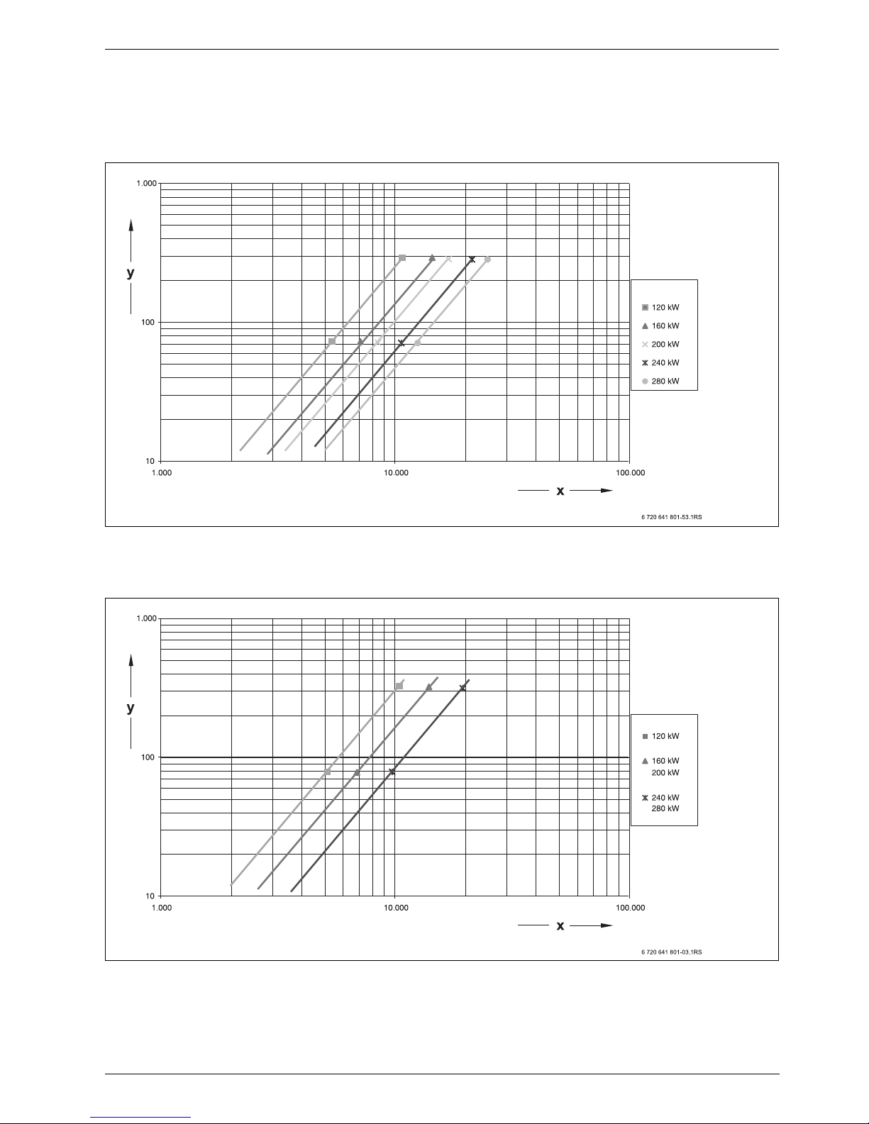
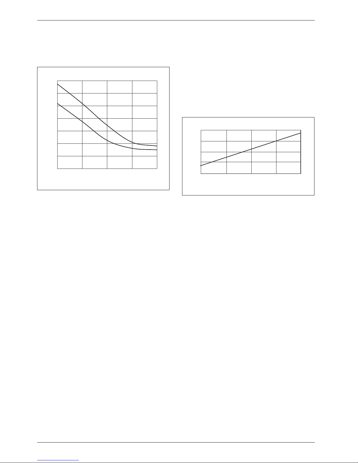
2.4 Pressure drop, water side
The pressure drop on the water side is the pressure
differential between the boiler flow and return
connections of the gas condensing boiler. It depends on
the boiler size and the heating water flow rate.
Fig. 14 Pressure drop on the heating water side without check valve
x Flow rate in l/h
y Pressure drop on the heating water side in mbar
Fig. 15 Pressure drop on the heating water side with check valve (cascade)
x Flow rate in l/h
y Pressure drop on the heating water side in mbar
Specification
6 720 645 817 (2010/09)
30
2.5 Boiler efficiency
The boiler efficiency ηK identifies the ratio of heat output
to heat input subject to the return temperature.
Fig. 16 Boiler efficiency subject to boiler return
temperature (average for this series of boilers)
ηKBoiler efficiency
ϑ Return temperature
1 Full load
2 Partial load
2.6 Standby loss
The standby loss qB is part of the rated heat input that
is required to achieve the specified boiler water
temperature. The cause of this loss is the cooling down
of the boiler through radiation and convection during the
standby time (burner idle time). Radiation and
convection result in part of the output being transferred
continuously from the boiler surface to the ambient air.
In addition to this surface loss, the boiler can also cool
down to a lesser degree through the chimney draught.
Fig. 17 Standby loss, relative to the rated heat input of
the boiler, subject to the average boiler water
temperature (average for this series of boilers)
qBStandby loss
ϑ
K
Average boiler water temperature
94
96
98
100
102
104
106
108
30 40 50 60 70
2
1
ηK [%]
ϑ [°C]
6 720 642 877-05.1il
0
0,1
0,2
30 40 50 60 70
qB [%]
ϑ
K
[°C]
6 720 642 877-06.1il
 Loading...