

Page 1

MX240™ Ethernet Services Router
Hardware Guide
Juniper Networks, Inc.
1194 North Mathilda Avenue
Sunnyvale, California 94089
USA
408-745-2000
www.juniper.net
Part Number: 530-022140-01, Revision 2
Page 2

This product includes the Envoy SNMP Engine, developed by Epilogue Technology, an Integrated Systems Company. Copyright © 1986-1997, Epilogue
Technology Corporation. All rights reserved. This program and its documentation were developed at private expense, and no part of them is in the public
domain.
This product includes memory allocation software developed by Mark Moraes, copyright © 1988, 1989, 1993, University of Toronto.
This product includes FreeBSD software developed by the University of California, Berkeley, and its contributors. All of the documentation and software
included in the 4.4BSD and 4.4BSD-Lite Releases is copyrighted by the Regents of the University of California. Copyright © 1979, 1980, 1983, 1986, 1988,
1989, 1991, 1992, 1993, 1994. The Regents of the University of California. All rights reserved.
GateD software copyright © 1995, the Regents of the University. All rights reserved. Gate Daemon was originated and developed through release 3.0 by
Cornell University and its collaborators. Gated is based on Kirton’s EGP, UC Berkeley’s routing daemon (routed), and DCN’s HELLO routing protocol.
Development of Gated has been supported in part by the National Science Foundation. Portions of the GateD software copyright © 1988, Regents of the
University of California. All rights reserved. Portions of the GateD software copyright © 1991, D. L. S. Associates.
This product includes software developed by Maker Communications, Inc., copyright © 1996, 1997, Maker Communications, Inc.
Juniper Networks, the Juniper Networks logo, NetScreen, and ScreenOS are registered trademarks of Juniper Networks, Inc. in the United States and other
countries. JUNOS and JUNOSe are trademarks of Juniper Networks, Inc. All other trademarks, service marks, registered trademarks, or registered service
marks are the property of their respective owners.
Juniper Networks assumes no responsibility for any inaccuracies in this document. Juniper Networks reserves the right to change, modify, transfer, or
otherwise revise this publication without notice.
Products made or sold by Juniper Networks or components thereof might be covered by one or more of the following patents that are owned by or licensed
to Juniper Networks: U.S. Patent Nos. 5,473,599, 5,905,725, 5,909,440, 6,192,051, 6,333,650, 6,359,479, 6,406,312, 6,429,706, 6,459,579, 6,493,347,
6,538,518, 6,538,899, 6,552,918, 6,567,902, 6,578,186, and 6,590,785.
MX240 Ethernet Services Router Hardware Guide
Copyright © 2008, Juniper Networks, Inc.
All rights reserved. Printed in USA.
Writing: Elizabeth Gardner, Sheila Nolte
Editing: Fran Mues
Illustration: Faith Bradford Brown
Cover Design: Edmonds Design
Revision History
29 February 2008—530-022140-01. Revision 2.
1 February 2008—530-022140-01. Revision 1.
The information in this document is current as of the date listed in the revision history.
YEAR 2000 NOTICE
Juniper Networks hardware and software products are Year 2000 compliant. The JUNOS software has no known time-related limitations through the year
2038. However, the NTP application is known to have some difficulty in the year 2036.
ii ■
Page 3

End User License Agreement
READ THIS END USER LICENSE AGREEMENT (“AGREEMENT”) BEFORE DOWNLOADING, INSTALLING, OR USING THE SOFTWARE. BY DOWNLOADING,
INSTALLING, OR USING THE SOFTWARE OR OTHERWISE EXPRESSING YOUR AGREEMENT TO THE TERMS CONTAINED HEREIN, YOU (AS CUSTOMER
OR IF YOU ARE NOT THE CUSTOMER, AS A REPRESENTATIVE/AGENT AUTHORIZED TO BIND THE CUSTOMER) CONSENT TO BE BOUND BY THIS
AGREEMENT. IF YOU DO NOT OR CANNOT AGREE TO THE TERMS CONTAINED HEREIN, THEN (A) DO NOT DOWNLOAD, INSTALL, OR USE THE SOFTWARE,
AND (B) YOU MAY CONTACT JUNIPER NETWORKS REGARDING LICENSE TERMS.
1. The Parties. The parties to this Agreement are Juniper Networks, Inc. and its subsidiaries (collectively “Juniper”), and the person or organization that
originally purchased from Juniper or an authorized Juniper reseller the applicable license(s) for use of the Software (“Customer”) (collectively, the “Parties”).
2. The Software. In this Agreement, “Software” means the program modules and features of the Juniper or Juniper-supplied software, and updates and
releases of such software, for which Customer has paid the applicable license or support fees to Juniper or an authorized Juniper reseller. “Embedded
Software” means Software which Juniper has embedded in the Juniper equipment.
3. License Grant. Subject to payment of the applicable fees and the limitations and restrictions set forth herein, Juniper grants to Customer a non-exclusive
and non-transferable license, without right to sublicense, to use the Software, in executable form only, subject to the following use restrictions:
a. Customer shall use the Embedded Software solely as embedded in, and for execution on, Juniper equipment originally purchased by Customer from
Juniper or an authorized Juniper reseller.
b. Customer shall use the Software on a single hardware chassis having a single processing unit, or as many chassis or processing units for which Customer
has paid the applicable license fees; provided, however, with respect to the Steel-Belted Radius or Odyssey Access Client software only, Customer shall use
such Software on a single computer containing a single physical random access memory space and containing any number of processors. Use of the
Steel-Belted Radius software on multiple computers requires multiple licenses, regardless of whether such computers are physically contained on a single
chassis.
c. Product purchase documents, paper or electronic user documentation, and/or the particular licenses purchased by Customer may specify limits to
Customer’s use of the Software. Such limits may restrict use to a maximum number of seats, registered endpoints, concurrent users, sessions, calls,
connections, subscribers, clusters, nodes, realms, devices, links, ports or transactions, or require the purchase of separate licenses to use particular features,
functionalities, services, applications, operations, or capabilities, or provide throughput, performance, configuration, bandwidth, interface, processing,
temporal, or geographical limits. In addition, such limits may restrict the use of the Software to managing certain kinds of networks or require the Software
to be used only in conjunction with other specific Software. Customer’s use of the Software shall be subject to all such limitations and purchase of all applicable
licenses.
d. For any trial copy of the Software, Customer’s right to use the Software expires 30 days after download, installation or use of the Software. Customer
may operate the Software after the 30-day trial period only if Customer pays for a license to do so. Customer may not extend or create an additional trial
period by re-installing the Software after the 30-day trial period.
e. The Global Enterprise Edition of the Steel-Belted Radius software may be used by Customer only to manage access to Customer’s enterprise network.
Specifically, service provider customers are expressly prohibited from using the Global Enterprise Edition of the Steel-Belted Radius software to support any
commercial network access services.
The foregoing license is not transferable or assignable by Customer. No license is granted herein to any user who did not originally purchase the applicable
license(s) for the Software from Juniper or an authorized Juniper reseller.
4. Use Prohibitions. Notwithstanding the foregoing, the license provided herein does not permit the Customer to, and Customer agrees not to and shall
not: (a) modify, unbundle, reverse engineer, or create derivative works based on the Software; (b) make unauthorized copies of the Software (except as
necessary for backup purposes); (c) rent, sell, transfer, or grant any rights in and to any copy of the Software, in any form, to any third party; (d) remove
any proprietary notices, labels, or marks on or in any copy of the Software or any product in which the Software is embedded; (e) distribute any copy of
the Software to any third party, including as may be embedded in Juniper equipment sold in the secondhand market; (f) use any ‘locked’ or key-restricted
feature, function, service, application, operation, or capability without first purchasing the applicable license(s) and obtaining a valid key from Juniper, even
if such feature, function, service, application, operation, or capability is enabled without a key; (g) distribute any key for the Software provided by Juniper
to any third party; (h) use the Software in any manner that extends or is broader than the uses purchased by Customer from Juniper or an authorized Juniper
reseller; (i) use the Embedded Software on non-Juniper equipment; (j) use the Software (or make it available for use) on Juniper equipment that the Customer
did not originally purchase from Juniper or an authorized Juniper reseller; (k) disclose the results of testing or benchmarking of the Software to any third
party without the prior written consent of Juniper; or (l) use the Software in any manner other than as expressly provided herein.
5. Audit. Customer shall maintain accurate records as necessary to verify compliance with this Agreement. Upon request by Juniper, Customer shall furnish
such records to Juniper and certify its compliance with this Agreement.
6. Confidentiality. The Parties agree that aspects of the Software and associated documentation are the confidential property of Juniper. As such, Customer
shall exercise all reasonable commercial efforts to maintain the Software and associated documentation in confidence, which at a minimum includes
restricting access to the Software to Customer employees and contractors having a need to use the Software for Customer’s internal business purposes.
■ iii
Page 4

7. Ownership. Juniper and Juniper's licensors, respectively, retain ownership of all right, title, and interest (including copyright) in and to the Software,
associated documentation, and all copies of the Software. Nothing in this Agreement constitutes a transfer or conveyance of any right, title, or interest in
the Software or associated documentation, or a sale of the Software, associated documentation, or copies of the Software.
8. Warranty, Limitation of Liability, Disclaimer of Warranty. The warranty applicable to the Software shall be as set forth in the warranty statement that
accompanies the Software (the “Warranty Statement”). Nothing in this Agreement shall give rise to any obligation to support the Software. Support services
may be purchased separately. Any such support shall be governed by a separate, written support services agreement. TO THE MAXIMUM EXTENT PERMITTED
BY LAW, JUNIPER SHALL NOT BE LIABLE FOR ANY LOST PROFITS, LOSS OF DATA, OR COSTS OR PROCUREMENT OF SUBSTITUTE GOODS OR SERVICES,
OR FOR ANY SPECIAL, INDIRECT, OR CONSEQUENTIAL DAMAGES ARISING OUT OF THIS AGREEMENT, THE SOFTWARE, OR ANY JUNIPER OR
JUNIPER-SUPPLIED SOFTWARE. IN NO EVENT SHALL JUNIPER BE LIABLE FOR DAMAGES ARISING FROM UNAUTHORIZED OR IMPROPER USE OF ANY
JUNIPER OR JUNIPER-SUPPLIED SOFTWARE. EXCEPT AS EXPRESSLY PROVIDED IN THE WARRANTY STATEMENT TO THE EXTENT PERMITTED BY LAW,
JUNIPER DISCLAIMS ANY AND ALL WARRANTIES IN AND TO THE SOFTWARE (WHETHER EXPRESS, IMPLIED, STATUTORY, OR OTHERWISE), INCLUDING
ANY IMPLIED WARRANTY OF MERCHANTABILITY, FITNESS FOR A PARTICULAR PURPOSE, OR NONINFRINGEMENT. IN NO EVENT DOES JUNIPER
WARRANT THAT THE SOFTWARE, OR ANY EQUIPMENT OR NETWORK RUNNING THE SOFTWARE, WILL OPERATE WITHOUT ERROR OR INTERRUPTION,
OR WILL BE FREE OF VULNERABILITY TO INTRUSION OR ATTACK. In no event shall Juniper’s or its suppliers’ or licensors’ liability to Customer, whether
in contract, tort (including negligence), breach of warranty, or otherwise, exceed the price paid by Customer for the Software that gave rise to the claim, or
if the Software is embedded in another Juniper product, the price paid by Customer for such other product. Customer acknowledges and agrees that Juniper
has set its prices and entered into this Agreement in reliance upon the disclaimers of warranty and the limitations of liability set forth herein, that the same
reflect an allocation of risk between the Parties (including the risk that a contract remedy may fail of its essential purpose and cause consequential loss),
and that the same form an essential basis of the bargain between the Parties.
9. Termination. Any breach of this Agreement or failure by Customer to pay any applicable fees due shall result in automatic termination of the license
granted herein. Upon such termination, Customer shall destroy or return to Juniper all copies of the Software and related documentation in Customer’s
possession or control.
10. Taxes. All license fees for the Software are exclusive of taxes, withholdings, duties, or levies (collectively “Taxes”). Customer shall be responsible for
paying Taxes arising from the purchase of the license, or importation or use of the Software.
11. Export. Customer agrees to comply with all applicable export laws and restrictions and regulations of any United States and any applicable foreign
agency or authority, and not to export or re-export the Software or any direct product thereof in violation of any such restrictions, laws or regulations, or
without all necessary approvals. Customer shall be liable for any such violations. The version of the Software supplied to Customer may contain encryption
or other capabilities restricting Customer’s ability to export the Software without an export license.
12. Commercial Computer Software. The Software is “commercial computer software” and is provided with restricted rights. Use, duplication, or disclosure
by the United States government is subject to restrictions set forth in this Agreement and as provided in DFARS 227.7201 through 227.7202-4, FAR 12.212,
FAR 27.405(b)(2), FAR 52.227-19, or FAR 52.227-14(ALT III) as applicable.
13. Interface Information. To the extent required by applicable law, and at Customer's written request, Juniper shall provide Customer with the interface
information needed to achieve interoperability between the Software and another independently created program, on payment of applicable fee, if any.
Customer shall observe strict obligations of confidentiality with respect to such information and shall use such information in compliance with any applicable
terms and conditions upon which Juniper makes such information available.
14. Third Party Software. Any licensor of Juniper whose software is embedded in the Software and any supplier of Juniper whose products or technology
are embedded in (or services are accessed by) the Software shall be a third party beneficiary with respect to this Agreement, and such licensor or vendor
shall have the right to enforce this Agreement in its own name as if it were Juniper. In addition, certain third party software may be provided with the
Software and is subject to the accompanying license(s), if any, of its respective owner(s). To the extent portions of the Software are distributed under and
subject to open source licenses obligating Juniper to make the source code for such portions publicly available (such as the GNU General Public License
(“GPL”) or the GNU Library General Public License (“LGPL”)), Juniper will make such source code portions (including Juniper modifications, as appropriate)
available upon request for a period of up to three years from the date of distribution. Such request can be made in writing to Juniper Networks, Inc., 1194
N. Mathilda Ave., Sunnyvale, CA 94089, ATTN: General Counsel. You may obtain a copy of the GPL at http://www.gnu.org/licenses/gpl.html, and a copy of
the LGPL at http://www.gnu.org/licenses/lgpl.html.
15. Miscellaneous. This Agreement shall be governed by the laws of the State of California without reference to its conflicts of laws principles. The provisions
of the U.N. Convention for the International Sale of Goods shall not apply to this Agreement. For any disputes arising under this Agreement, the Parties
hereby consent to the personal and exclusive jurisdiction of, and venue in, the state and federal courts within Santa Clara County, California. This Agreement
constitutes the entire and sole agreement between Juniper and the Customer with respect to the Software, and supersedes all prior and contemporaneous
agreements relating to the Software, whether oral or written (including any inconsistent terms contained in a purchase order), except that the terms of a
separate written agreement executed by an authorized Juniper representative and Customer shall govern to the extent such terms are inconsistent or conflict
with terms contained herein. No modification to this Agreement nor any waiver of any rights hereunder shall be effective unless expressly assented to in
writing by the party to be charged. If any portion of this Agreement is held invalid, the Parties agree that such invalidity shall not affect the validity of the
remainder of this Agreement. This Agreement and associated documentation has been written in the English language, and the Parties agree that the English
version will govern. (For Canada: Les parties aux présentés confirment leur volonté que cette convention de même que tous les documents y compris tout
avis qui s'y rattaché, soient redigés en langue anglaise. (Translation: The parties confirm that this Agreement and all related documentation is and will be
in the English language)).
iv ■
Page 5

Table of Contents
About This Guide xvii
Objectives ....................................................................................................xvii
Audience .....................................................................................................xvii
Documentation Conventions ......................................................................xviii
List of Technical Publications ........................................................................xix
Obtaining Documentation ..........................................................................xxvi
Documentation Feedback ...........................................................................xxvi
Requesting Technical Support ....................................................................xxvii
Part 1 MX240 Router Overview
Chapter 1 Router Overview 3
Router Description ..........................................................................................3
Component Redundancy .................................................................................4
Chapter 2 Hardware Components 5
Router Chassis .................................................................................................5
Midplane .........................................................................................................8
Dense Port Concentrators (DPCs) ....................................................................8
DPC Components ...................................................................................10
Host Subsystem .............................................................................................11
Switch Control Board (SCB) .....................................................................11
SCB Slots ..........................................................................................12
SCB Redundancy ..............................................................................12
SCB Components ..............................................................................13
SCB LEDs .........................................................................................13
Routing Engine .......................................................................................14
Routing Engine Components ............................................................14
Routing Engine Interface Ports .........................................................16
Routing Engine Boot Sequence .........................................................16
Cable Management System ...........................................................................17
Craft Interface ...............................................................................................17
Alarm LEDs and Alarm Cutoff/Lamp Test Button ....................................18
Host Subsystem LEDs .............................................................................19
Power Supply LEDs .................................................................................19
DPC LEDs ...............................................................................................20
Table of Contents ■ v
Page 6

MX240 Ethernet Services Router Hardware Guide
SCB LEDs ................................................................................................20
Fan LEDs ................................................................................................20
Alarm Relay Contacts ..............................................................................21
Power Supplies ..............................................................................................21
AC Power Supply ....................................................................................21
AC Power Supply LEDs .....................................................................22
DC Power Supply ....................................................................................23
DC Power Supply Configurations for the MX240 Router ...................23
DC Power Supply LEDs .....................................................................24
Cooling System .............................................................................................24
Part 2 Setting Up the Router
Chapter 3 Preparing the Site for Router Installation 29
Site Preparation Checklist ..............................................................................29
Cabinet Requirements ...................................................................................30
Cabinet Size and Clearance Requirements ..............................................30
Cabinet Airflow Requirements ................................................................30
Rack Requirements .......................................................................................31
Rack Size and Strength ...........................................................................31
Spacing of Mounting Bracket Holes .........................................................32
Connection to Building Structure ............................................................32
Clearance Requirements for Airflow and Hardware Maintenance ..................32
Chapter 4 Installation Overview 35
Chapter 5 Unpacking the Router 37
Tools and Parts Required ..............................................................................37
Unpacking the Router ....................................................................................37
Verifying Parts Received ................................................................................38
Chapter 6 Installing the Mounting Hardware 41
Installing the Mounting Hardware for a Rack or Cabinet ...............................41
Moving the Mounting Brackets for Center-Mounting the Router ....................43
Chapter 7 Installing the Router 45
Safety Requirements, Warnings, and Guidelines ...........................................45
Installing the Router Using a Mechanical Lift .................................................45
Tools Required ........................................................................................46
Installing the Router Using a Lift .............................................................46
vi ■ Table of Contents
Page 7

Table of Contents
Chapter 8 Connecting the Router 49
Tools and Parts Required ..............................................................................49
Connecting the Router to Management and Alarm Devices ...........................49
Connecting to a Network for Out-of-Band Management ..........................50
Connecting to a Management Console or Auxiliary Device .....................50
Connecting to an External Alarm-Reporting Device ................................50
Connecting DPC Cables .................................................................................51
Chapter 9 Grounding and Providing Power to the Router 53
Tools and Parts Required ..............................................................................53
Grounding the Router ....................................................................................54
Connecting Power to an AC-Powered Router .................................................54
Powering On an AC-Powered Router .............................................................55
Connecting Power to a DC-Powered Router ..................................................56
Powering On a DC-Powered Router ...............................................................58
Powering Off the Router ................................................................................59
Chapter 10 Configuring JUNOS Software 61
Configuring the JUNOS Software ...................................................................61
Part 3 Hardware Maintenance, Troubleshooting, and Replacement
Procedures
Chapter 11 Maintaining Hardware Components 67
Tools and Parts Required ..............................................................................67
Routine Maintenance Procedures ..................................................................67
Maintaining Cooling System Components .....................................................68
Maintaining the Air Filter ........................................................................68
Maintaining the Fan Tray ........................................................................68
Maintaining the Host Subsystem ...................................................................70
Maintaining Packet Forwarding Engine Components ....................................72
Maintaining DPCs ...................................................................................72
Maintaining DPC Cables ..........................................................................74
Handling and Storing DPCs .....................................................................74
Holding a DPC ..................................................................................75
Storing a DPC ...................................................................................77
Maintaining the Power Supplies ....................................................................78
Table of Contents ■ vii
Page 8

MX240 Ethernet Services Router Hardware Guide
Chapter 12 Troubleshooting Hardware Components 79
Overview of Troubleshooting Resources ........................................................79
Juniper Networks Technical Assistance Center ........................................79
Command-Line Interface ........................................................................79
Chassis and Interface Alarm Messages ....................................................80
Alarm Relay Contacts ..............................................................................80
LEDs .......................................................................................................80
Craft Interface LEDs .........................................................................80
Component LEDs .............................................................................81
Troubleshooting the Cooling System .............................................................82
Troubleshooting DPCs ...................................................................................83
Troubleshooting the Power System ...............................................................84
Chapter 13 Replacing Hardware Components 87
Field-Replaceable Units (FRUs) ......................................................................87
Tools and Parts Required ..............................................................................88
Replacing the Craft Interface .........................................................................89
Removing the Craft Interface ..................................................................89
Installing the Craft Interface ....................................................................90
Replacing Alarm Relay Wires ..................................................................91
Disconnecting the Alarm Relay Wires ..............................................91
Connecting the Alarm Relay Wires ...................................................92
Replacing Cooling System Components ........................................................92
Replacing the Fan Tray ...........................................................................92
Removing the Fan Tray ....................................................................92
Installing the Fan Tray ......................................................................93
Replacing the Air Filter ...........................................................................94
Removing an Air Filter .....................................................................94
Installing the Air Filter ......................................................................95
Replacing Host Subsystem Components .......................................................96
Taking the Host Subsystem Offline .........................................................96
Replacing an SCB ....................................................................................97
Operating and Positioning the SCB Ejectors .....................................98
Removing an SCB .............................................................................99
Installing an SCB ............................................................................100
Replacing a Routing Engine .........................................................................102
Removing a Routing Engine ..................................................................102
Installing a Routing Engine ...................................................................103
Replacing Connections to Routing Engine Interface Ports ...........................104
Replacing the Management Ethernet Cable ...........................................105
Removing the Management Ethernet Cable ...................................105
Installing the Management Ethernet Cable .....................................105
Replacing the Console or Auxiliary Cable ..............................................105
Disconnecting the Cable from a Management Console or Auxiliary
Device ......................................................................................105
Connecting the Cable to a Management Console or Auxiliary
Device ......................................................................................106
viii ■ Table of Contents
Page 9

Table of Contents
Replacing DPCs and Transceivers ................................................................106
Replacing a DPC ...................................................................................106
Removing a DPC ............................................................................106
Installing a DPC ..............................................................................108
Removing an SFP or XFP Transceiver ...................................................110
Installing an SFP or XFP Transceiver .....................................................112
Replacing Power System Components ........................................................112
Removing an AC Power Supply .............................................................113
Installing an AC Power Supply ..............................................................114
Removing a DC Power Supply ..............................................................114
Installing a DC Power Supply ................................................................116
Replacing an AC Power Cord ................................................................118
Disconnecting an AC Power Cord ...................................................119
Connecting an AC Power Supply Cord ............................................119
Replacing a DC Power Supply Cable .....................................................119
Disconnecting a DC Power Supply Cable ........................................120
Connecting a DC Power Supply Cable ............................................120
Replacing the Cable Management System ...................................................121
Removing the Cable Management System ............................................121
Installing the Cable Management System ..............................................122
Part 4 Appendixes
Appendix A Safety and Regulatory Compliance Information 125
Definition of Safety Warning Levels ............................................................125
Safety Guidelines and Warnings ..................................................................126
General Safety Guidelines and Warnings ...............................................127
Qualified Personnel Warning ..........................................................127
Restricted Access Area Warning .....................................................128
Preventing Electrostatic Discharge Damage ...................................130
Fire Safety Requirements ......................................................................130
Fire Suppression .............................................................................131
Fire Suppression Equipment ...........................................................131
Installation Safety Guidelines and Warnings .........................................131
Chassis-Lifting Guidelines ...............................................................132
Installation Instructions Warning ....................................................132
Rack-Mounting Requirements and Warnings ..................................133
Ramp Warning ...............................................................................136
Laser and LED Safety Guidelines and Warnings ....................................136
General Laser Safety Guidelines ......................................................137
Class 1 Laser Product Warning .......................................................137
Class 1 LED Product Warning .........................................................137
Laser Beam Warning ......................................................................138
Radiation from Open Port Apertures Warning ................................139
Maintenance and Operational Safety Guidelines and Warnings ............139
Battery Handling Warning ..............................................................140
Jewelry Removal Warning ..............................................................141
Table of Contents ■ ix
Page 10

MX240 Ethernet Services Router Hardware Guide
Lightning Activity Warning .............................................................142
Operating Temperature Warning ....................................................142
Product Disposal Warning ..............................................................143
Electrical Safety Guidelines and Warnings ............................................144
In Case of Electrical Accident .........................................................144
General Electrical Safety Guidelines and Warnings .........................145
AC Power Electrical Safety Guidelines ............................................148
DC Power Electrical Safety Guidelines and Warnings .....................149
Agency Approvals and Compliance .............................................................155
Agency Approvals .................................................................................155
Compliance Statements for NEBs Requirements ...................................156
Compliance Statements for EMC Requirements ....................................157
Canada ...........................................................................................157
European Community ....................................................................157
Japan ..............................................................................................158
United States ..................................................................................159
Compliance Statements for Environmental Requirements ....................159
Lithium Battery ..............................................................................159
Compliance Statements for Acoustic Noise ...........................................159
Appendix B Physical Specifications 161
Physical Specifications ................................................................................161
Appendix C Router Environmental Specifications 163
Router Environmental Specifications ...........................................................163
Appendix D Power Guidelines, Requirements, and Specifications 165
Chassis Grounding Specifications ................................................................165
Grounding Cable Lug Specification ........................................................165
Grouding Cable Specification ................................................................166
DC Power Specifications and Requirements ................................................166
DC Power Specifications .......................................................................166
DC Power System Electrical Specifications .....................................167
DC Power Supply Electrical Specifications ......................................167
Power Consumption for DC-Powered Routers .......................................167
DC Power Circuit Breaker Specifications ...............................................169
DC Power Cable Specifications .............................................................170
DC Power Cable Lug Specifications ................................................171
DC Power Cable Specifications .......................................................171
AC Power Specifications and Requirements ................................................171
AC Power Specifications .......................................................................172
AC Power System Electrical Specifications .....................................172
AC Power Supply Electrical Specifications ......................................172
Power Consumption for AC-Powered Routers .......................................172
x ■ Table of Contents
Page 11

Table of Contents
AC Power Circuit Breaker Specifications ...............................................174
AC Power Cord Specifications ...............................................................174
Site Electrical Wiring Guidelines ..................................................................176
Distance Limitations for Signaling .........................................................176
Radio Frequency Interference ...............................................................176
Electromagnetic Compatibility ..............................................................176
Appendix E Cable and Wire Guidelines and Specifications 179
Network Cable Specifications and Guidelines ..............................................179
Fiber-Optic and Network Cable Specifications ......................................179
Signal Loss in Multimode and Single-Mode Fiber-Optic Cable ...............179
Attenuation and Dispersion in Fiber-Optic Cable ..................................180
Calculating Power Budget for Fiber-Optic Cable ....................................181
Calculating Power Margin for Fiber-Optic Cable ....................................181
Routing Engine Interface Cable and Wire Specifications ..............................183
Appendix F Cable Connector Pinouts 185
RJ-45 Connector Pinouts for the Routing Engine ETHERNET Port ...............185
RJ-45 Connector Pinouts for the Routing Engine AUX and CONSOLE
Ports .....................................................................................................185
Appendix G Installing the Router Without a Mechanical Lift 187
Tools and Parts Required ............................................................................187
Removing Components from the Chassis ....................................................187
Removing the Power Supplies ...............................................................188
Removing the Fan Tray .........................................................................189
Removing SCBs .....................................................................................189
Removing DPCs ....................................................................................190
Installing the Chassis in the Rack Manually .................................................192
Reinstalling Components in the Chassis ......................................................193
Reinstalling the Power Supplies ............................................................193
Reinstalling the Fan Tray ......................................................................194
Reinstalling SCBs ..................................................................................195
Reinstalling DPCs ..................................................................................196
Appendix H Contacting Customer Support and Returning Hardware 197
Locating Component Serial Numbers ..........................................................197
MX240 Chassis Serial Number Label .....................................................198
SCB Serial Number Label ......................................................................199
DPC Serial Number Label ......................................................................200
Power Supply Serial Number Labels ......................................................200
Routing Engine Serial Number Label .....................................................201
Contacting Customer Support ......................................................................202
Information You Might Need to Supply to JTAC ....................................202
Table of Contents ■ xi
Page 12

MX240 Ethernet Services Router Hardware Guide
Return Procedure ........................................................................................203
Tools and Parts Required ............................................................................204
Packing the Router for Shipment .................................................................204
Packing Components for Shipment .............................................................205
Part 5 Index
Index ...........................................................................................................209
xii ■ Table of Contents
Page 13

List of Figures
Figure 1: Front View of a Fully Configured Router Chassis ..............................6
Figure 2: Rear View of a Fully Configured AC-Powered Router Chassis (110
V) ..............................................................................................................6
Figure 3: Rear View of a Fully Configured AC-Powered Router Chassis
(220V) .......................................................................................................7
Figure 4: Rear View of a Fully Configured DC-Powered Router Chassis ...........7
Figure 5: Midplane ..........................................................................................8
Figure 6: Typical DPCs Supported on the MX240 Router .................................9
Figure 7: DPC Installed Horizontally in the MX240 Router ..............................9
Figure 8: SCB .................................................................................................12
Figure 9: Routing Engine ...............................................................................14
Figure 10: USB Memory Device in a Routing Engine .....................................15
Figure 11: Cable Management System ..........................................................17
Figure 12: Cable Management System Installed on the Router ......................17
Figure 13: Front Panel of the Craft Interface .................................................18
Figure 14: Alarm Relay Contacts ...................................................................21
Figure 15: AC Power Supply ..........................................................................22
Figure 16: DC Power Supply ..........................................................................23
Figure 17: Airflow Through Chassis ...............................................................25
Figure 18: Fan Tray .......................................................................................25
Figure 19: Air Filter .......................................................................................26
Figure 20: Typical Open-Frame Rack ............................................................32
Figure 21: Chassis Dimensions and Clearance Requirements ........................33
Figure 22: Contents of the Shipping Crate .....................................................38
Figure 23: Installing the Front Mounting Hardware for a Four-Post Rack or
Cabinet ...................................................................................................42
Figure 24: Installing the Mounting Hardware for an Open-Frame Rack .........43
Figure 25: Installing the Router in the Rack ...................................................47
Figure 26: Routing Engine Management Ports ...............................................49
Figure 27: RJ-45 Cable Connector ..................................................................50
Figure 28: Alarm Relay Contacts ...................................................................51
Figure 29: Attaching a Cable to a DPC ...........................................................52
Figure 30: Connecting AC Power to the Router .............................................55
Figure 31: Connecting DC Power to the Router .............................................58
Figure 32: DPC Edges ....................................................................................75
Figure 33: Do Not Grasp the Connector Edge ................................................76
Figure 34: Do Not Rest the DPC on an Edge ..................................................77
Figure 35: Airflow Through the Chassis .........................................................82
Figure 36: Removing the Craft Interface ........................................................90
Figure 37: Installing a Craft Interface ............................................................91
Figure 38: Alarm Relay Contacts ...................................................................91
Figure 39: Removing the Fan Tray from an MX240 Router ...........................93
List of Figures ■ xiii
Page 14

MX240 Ethernet Services Router Hardware Guide
Figure 40: Installing the Fan Tray in an MX240 Router .................................94
Figure 41: Removing the Air Filter from an MX240 Router ...........................95
Figure 42: Installing the Air Filter in an MX240 Router ..................................96
Figure 43: Removing an SCB .........................................................................99
Figure 44: Installing an SCB .........................................................................102
Figure 45: Removing a Routing Engine .......................................................103
Figure 46: Installing a Routing Engine .........................................................104
Figure 47: Routing Engine Interface Ports ...................................................104
Figure 48: Cable Connectors .......................................................................105
Figure 49: Removing a DPC ........................................................................108
Figure 50: Installing a DPC ..........................................................................110
Figure 51: Attaching a Cable to a DPC .........................................................110
Figure 52: Removing SFPs or XFPs .............................................................111
Figure 53: Removing an AC Power Supply ..................................................113
Figure 54: Installing an AC Power Supply ....................................................114
Figure 55: Removing a DC Power Supply from an MX240 Router ...............116
Figure 56: Installing a DC Power Supply in an MX240 Router .....................118
Figure 57: Connecting DC Power to the Router ...........................................118
Figure 58: Connecting Power Cables to the DC Power Supply .....................121
Figure 59: Removing or Installing the Cable Management System ..............122
Figure 60: Placing a Component into an Electrostatic Bag ...........................130
Figure 61: Grounding Cable Lug ..................................................................166
Figure 62: Typical DC Source Cabling to the Router ....................................170
Figure 63: DC Power Cable Lug ...................................................................171
Figure 64: AC Plug Types ............................................................................175
Figure 65: Removing a Power Supply Before Installing the Router ..............188
Figure 66: Removing the Fan Tray ..............................................................189
Figure 67: Removing an SCB .......................................................................190
Figure 68: Removing a DPC ........................................................................191
Figure 69: Installing the Router in the Rack .................................................193
Figure 70: Reinstalling a Power Supply ........................................................194
Figure 71: Installing a Fan Tray ...................................................................195
Figure 72: Installing an SCB .........................................................................196
Figure 73: Installing a DPC ..........................................................................196
Figure 74: Serial Number ID Label ..............................................................198
Figure 75: MX240 Chassis Serial Number Label ..........................................199
Figure 76: SCB Serial Number Label ............................................................199
Figure 77: DPC Serial Number Label ...........................................................200
Figure 78: AC Power Supply Serial Number Label .......................................201
Figure 79: DC Power Supply Serial Number Label .......................................201
Figure 80: Routing Engine Serial Number Label ..........................................202
xiv ■ List of Figures
Page 15

List of Tables
Table 1: Notice Icons ..................................................................................xviii
Table 2: Text and Syntax Conventions ........................................................xviii
Table 3: Technical Documentation for Supported Routing Platforms .............xx
Table 4: JUNOS Software Network Operations Guides ................................xxiv
Table 5: JUNOS Software with Enhanced Services Documentation .............xxiv
Table 6: Additional Books Available Through
http://www.juniper.net/books ................................................................xxv
Table 7: Four-Port 10-Gigabit Ethernet DPC LEDs ..........................................10
Table 8: 40-Port Gigabit Ethernet DPC LEDs ..................................................10
Table 9: Switch Control Board LEDs ..............................................................13
Table 10: Routing Engine LEDs .....................................................................16
Table 11: Alarm LEDs and Alarm Cutoff/Lamp Test Button ...........................19
Table 12: Host Subsystem LEDs ....................................................................19
Table 13: Power Supply LEDs on the Craft Interface .....................................19
Table 14: DPC LEDs ......................................................................................20
Table 15: SCB LEDs .......................................................................................20
Table 16: Fan LEDs .......................................................................................20
Table 17: AC Power Supply LEDs ..................................................................23
Table 18: DC Power Supply LEDs ..................................................................24
Table 19: Site Preparation Checklist ..............................................................29
Table 20: Parts List for a Fully Configured Router ..........................................39
Table 21: Accessory Box Parts List ................................................................39
Table 22: Four-Post Rack or Cabinet Mounting Hole Locations ......................41
Table 23: Field-Replaceable Units ..................................................................88
Table 24: Tools and Parts Required ...............................................................88
Table 25: Physical Specifications .................................................................161
Table 26: Router Environmental Specifications ...........................................163
Table 27: Grounding Cable Specifications ....................................................166
Table 28: DC Power System Electrical Specifications ...................................167
Table 29: DC Power Supply Electrical Specifications ...................................167
Table 30: DC-Powered Base Router Power Requirements ...........................168
Table 31: Component Power Requirements ................................................168
Table 32: DC Power Cable Specifications ....................................................171
Table 33: AC Power System Electrical Specifications ...................................172
Table 34: AC Power Supply Electrical Specifications ....................................172
Table 35: AC Base Router Power Requirements ..........................................173
Table 36: Component Power Requirements for AC-Powered Routers ..........173
Table 37: AC Power Cord Specifications ......................................................175
Table 38: Estimated Values for Factors Causing Link Loss .........................181
Table 39: Cable and Wire Specifications for Routing Engine Management
and Alarm Interfaces ............................................................................183
List of Tables ■ xv
Page 16

MX240 Ethernet Services Router Hardware Guide
Table 40: RJ-45 Connector Pinout for the Routing Engine ETHERNET
Port .......................................................................................................185
Table 41: RJ-45 Connector Pinout for the AUX and CONSOLE Ports ............186
xvi ■ List of Tables
Page 17

About This Guide
This preface provides the following guidelines for using the MX240 Ethernet Services
Router Hardware Guide:
■ Objectives on page xvii
■ Audience on page xvii
■ Documentation Conventions on page xviii
■ List of Technical Publications on page xix
■ Obtaining Documentation on page xxvi
■ Documentation Feedback on page xxvi
■ Requesting Technical Support on page xxvii
Objectives
This manual describes hardware components, installation, basic configuration, and
basic troubleshooting procedures for the Juniper Networks MX240 Ethernet Services
Router. It explains how to prepare your site for router installation, unpack and install
the hardware, power on the router, perform initial software configuration, and
perform routine maintenance. After completing the installation and basic configuration
procedures covered in this manual, see the JUNOS software configuration guides for
information about further JUNOS software configuration.
Audience
NOTE: For additional information about Juniper Networks Ethernet Services routers
and the Dense Port Concentrators (DPCs) they support—either corrections to or
information that might have been omitted from this guide—see the hardware release
notes at http://www.juniper.net/.
This guide is designed for network administrators who are installing and maintaining
a Juniper Networks router or preparing a site for router installation. To use this guide,
you need a broad understanding of networks in general, the Internet in particular,
networking principles, and network configuration. Any detailed discussion of these
concepts is beyond the scope of this guide.
Objectives ■ xvii
Page 18
MX240 Ethernet Services Router Hardware Guide
Documentation Conventions
Table 1 on page xviii defines the notice icons used in this guide.
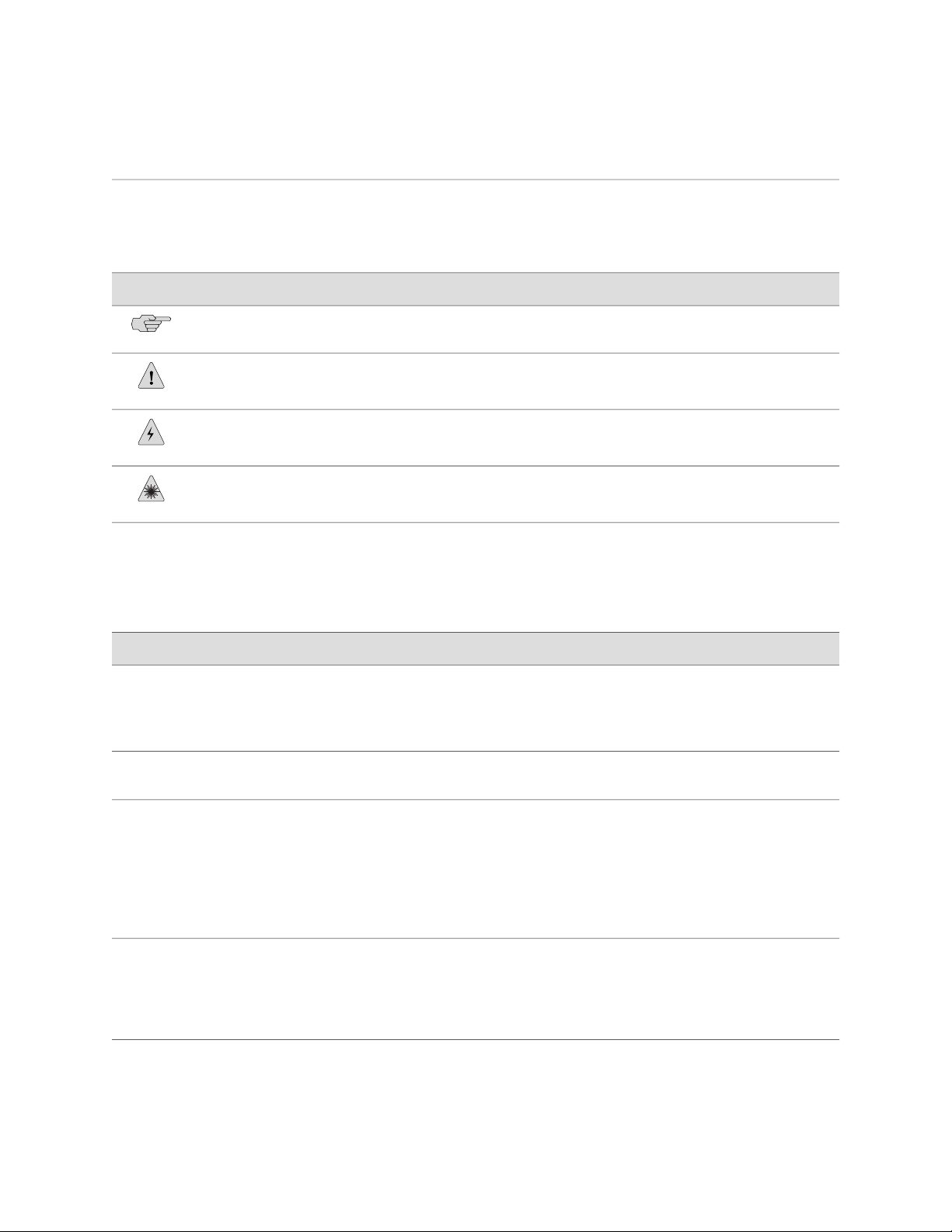
Table 1: Notice Icons
DescriptionMeaningIcon
Indicates important features or instructions.Informational note
Indicates a situation that might result in loss of data or hardware damage.Caution
Alerts you to the risk of personal injury or death.Warning
Alerts you to the risk of personal injury from a laser.Laser warning
Table 2 on page xviii defines the text and syntax conventions used in this guide.
Table 2: Text and Syntax Conventions
Bold text like this
Fixed-width text like this
Italic text like this
Italic text like this
Represents text that you type.
Represents output that appears on the
terminal screen.
Introduces important new terms.
■
Identifies book names.
■
Identifies RFC and Internet draft
■
titles.
Represents variables (options for which
you substitute a value) in commands or
configuration statements.
ExamplesDescriptionConvention
To enter configuration mode, type the
configure command:
user@host> configure
user@host> show chassis alarms
No alarms currently active
A policy term is a named structure
■
that defines match conditions and
actions.
JUNOS System Basics Configuration
■
Guide
RFC 1997, BGP Communities
■
Attribute
Configure the machine’s domain name:
[edit]
root@# set system domain-name
domain-name
xviii ■ Documentation Conventions
Page 19

Table 2: Text and Syntax Conventions (continued)
About This Guide
ExamplesDescriptionConvention
Plain text like this
| (pipe symbol)
# (pound sign)
[ ] (square brackets)
Indention and braces ( { } )
; (semicolon)
Represents names of configuration
statements, commands, files, and
directories; IP addresses; configuration
hierarchy levels; or labels on routing
platform components.
Enclose optional keywords or variables.< > (angle brackets)
Indicates a choice between the mutually
exclusive keywords or variables on either
side of the symbol. The set of choices is
often enclosed in parentheses for clarity.
Indicates a comment specified on the
same line as the configuration statement
to which it applies.
Enclose a variable for which you can
substitute one or more values.
Identify a level in the configuration
hierarchy.
Identifies a leaf statement at a
configuration hierarchy level.
To configure a stub area, include
■
the stub statement at the [edit
protocols ospf area area-id]
hierarchy level.
The console port is labeled
■
CONSOLE.
stub <default-metric metric>;
broadcast | multicast
(string1 | string2 | string3)
rsvp { # Required for dynamic MPLS only
community name members [
community-ids ]
[edit]
routing-options {
static {
route default {
nexthop address;
retain;
}
}
}
J-Web GUI Conventions
Bold text like this
> (bold right angle bracket)
List of Technical Publications
Table 3 on page xx lists the software and hardware guides and release notes for
Juniper Networks J-series, M-series, MX-series, and T-series routing platforms and
describes the contents of each document. Table 4 on page xxiv lists the books included
in the Network Operations Guide series. Table 5 on page xxiv lists the manuals and
release notes supporting JUNOS software with enhanced services. All documents are
available at http://www.juniper.net/techpubs/.
Represents J-Web graphical user
interface (GUI) items you click or select.
Separates levels in a hierarchy of J-Web
selections.
In the Logical Interfaces box, select
■
All Interfaces.
To cancel the configuration, click
■
Cancel.
In the configuration editor hierarchy,
select Protocols>Ospf.
List of Technical Publications ■ xix
Page 20

MX240 Ethernet Services Router Hardware Guide
Table 6 on page xxv lists additional books on Juniper Networks solutions that you can
order through your bookstore. A complete list of such books is available at
http://www.juniper.net/books.
Table 3: Technical Documentation for Supported Routing Platforms
DescriptionBook
JUNOS Software for Supported Routing Platforms
Access Privilege
Explains how to configure access privileges in user classes by using
permission flags and regular expressions. Lists the permission flags
along with their associated command-line interface (CLI) operational
mode commands and configuration statements.
Class of Service
CLI User Guide
Feature Guide
High Availability
MPLS Applications
Multicast Protocols
Multiplay Solutions
Provides an overview of the class-of-service (CoS) functions of the
JUNOS software and describes how to configure CoS features,
including configuring multiple forwarding classes for transmitting
packets, defining which packets are placed into each output queue,
scheduling the transmission service level for each queue, and
managing congestion through the random early detection (RED)
algorithm.
Describes how to use the JUNOS command-line interface (CLI) to
configure, monitor, and manage Juniper Networks routing
platforms. This material was formerly covered in the JUNOS System
Basics Configuration Guide.
Provides a detailed explanation and configuration examples for
several of the most complex features in the JUNOS software.
Provides an overview of hardware and software resources that
ensure a high level of continuous routing platform operation and
describes how to configure high availability (HA) features such as
nonstop active routing (NSR) and graceful Routing Engine
switchover (GRES).
Provides an overview of traffic engineering concepts and describes
how to configure traffic engineering protocols.
Provides an overview of multicast concepts and describes how to
configure multicast routing protocols.
Describes how you can deploy IPTV and voice over IP (VoIP)
services in your network.
MX-series Solutions Guide
Network Interfaces
Network Management
xx ■ List of Technical Publications
Describes common configuration scenarios for the Layer 2 features
supported on the MX-series routers, including basic bridged VLANs
with normalized VLAN tags, aggregated Ethernet links, bridge
domains, Multiple Spanning Tree Protocol (MSTP), and integrated
routing and bridging (IRB).
Provides an overview of the network interface functions of the
JUNOS software and describes how to configure the network
interfaces on the routing platform.
Provides an overview of network management concepts and
describes how to configure various network management features,
such as SNMP and accounting options.
Page 21

Table 3: Technical Documentation for Supported Routing Platforms (continued)
DescriptionBook
About This Guide
Policy Framework
Routing Protocols
Secure Configuration Guide for Common Criteria
and JUNOS-FIPS
Services Interfaces
Software Installation and Upgrade Guide
System Basics
VPNs
Provides an overview of policy concepts and describes how to
configure routing policy, firewall filters, and forwarding options.
Provides an overview of routing concepts and describes how to
configure routing, routing instances, and unicast routing protocols.
Provides an overview of secure Common Criteria and JUNOS-FIPS
protocols for the JUNOS software and describes how to install and
configure secure Common Criteria and JUNOS-FIPS on a routing
platform.
Provides an overview of the services interfaces functions of the
JUNOS software and describes how to configure the services
interfaces on the router.
Describes the JUNOS software components and packaging and
explains how to initially configure, reinstall, and upgrade the JUNOS
system software. This material was formerly covered in the JUNOS
System Basics Configuration Guide.
Describes Juniper Networks routing platforms and explains how
to configure basic system parameters, supported protocols and
software processes, authentication, and a variety of utilities for
managing your router on the network.
Provides an overview and describes how to configure Layer 2 and
Layer 3 virtual private networks (VPNs), virtual private LAN service
(VPLS), and Layer 2 circuits. Provides configuration examples.
JUNOS References
Hierarchy and RFC Reference
Interfaces Command Reference
Routing Protocols and Policies Command
Reference
System Basics and Services Command Reference
System Log Messages Reference
Describes the JUNOS configuration mode commands. Provides a
hierarchy reference that displays each level of a configuration
hierarchy, and includes all possible configuration statements that
can be used at that level. This material was formerly covered in
the JUNOS System Basics Configuration Guide.
Describes the JUNOS software operational mode commands you
use to monitor and troubleshoot interfaces.
Describes the JUNOS software operational mode commands you
use to monitor and troubleshoot routing policies and protocols,
including firewall filters.
Describes the JUNOS software operational mode commands you
use to monitor and troubleshoot system basics, including
commands for real-time monitoring and route (or path) tracing,
system software management, and chassis management. Also
describes commands for monitoring and troubleshooting services
such as class of service (CoS), IP Security (IPSec), stateful firewalls,
flow collection, and flow monitoring.
Describes how to access and interpret system log messages
generated by JUNOS software modules and provides a reference
page for each message.
List of Technical Publications ■ xxi
Page 22

MX240 Ethernet Services Router Hardware Guide
Table 3: Technical Documentation for Supported Routing Platforms (continued)
DescriptionBook
J-Web User Guide
J-Web Interface User Guide
Describes how to use the J-Web graphical user interface (GUI) to
configure, monitor, and manage Juniper Networks routing
platforms.
JUNOS API and Scripting Documentation
JUNOScript API Guide
Describes how to use the JUNOScript application programming
interface (API) to monitor and configure Juniper Networks routing
platforms.
JUNOS XML API Configuration Reference
JUNOS XML API Operational Reference
NETCONF API Guide
JUNOS Configuration and Diagnostic Automation
Guide
Hardware Documentation
Hardware Guide
PIC Guide
DPC Guide
JUNOScope Documentation
JUNOScope Software User Guide
Provides reference pages for the configuration tag elements in the
JUNOS XML API.
Provides reference pages for the operational tag elements in the
JUNOS XML API.
Describes how to use the NETCONF API to monitor and configure
Juniper Networks routing platforms.
Describes how to use the commit script and self-diagnosis features
of the JUNOS software. This guide explains how to enforce custom
configuration rules defined in scripts, how to use commit script
macros to provide simplified aliases for frequently used
configuration statements, and how to configure diagnostic event
policies.
Describes how to install, maintain, and troubleshoot routing
platforms and components. Each platform has its own hardware
guide.
Describes the routing platform's Physical Interface Cards (PICs).
Each platform has its own PIC guide.
Describes the Dense Port Concentrators (DPCs) for all MX-series
routers.
Describes the JUNOScope software graphical user interface (GUI),
how to install and administer the software, and how to use the
software to manage routing platform configuration files and monitor
routing platform operations.
Advanced Insight Solutions (AIS) Documentation
Advanced Insight Solutions Guide
J-series Routing Platform Documentation
xxii ■ List of Technical Publications
Describes the Advanced Insight Manager (AIM) application, which
provides a gateway between JUNOS devices and Juniper Support
Systems (JSS) for case management and intelligence updates.
Explains how to run AI scripts on Juniper Networks devices.
Page 23

Table 3: Technical Documentation for Supported Routing Platforms (continued)
DescriptionBook
About This Guide
Getting Started Guide
Basic LAN and WAN Access Configuration Guide
Advanced WAN Access Configuration Guide
Administration Guide
Release Notes
JUNOS Release Notes
Provides an overview, basic instructions, and specifications for
J-series routing platforms. The guide explains how to prepare your
site for installation, unpack and install the router and its
components, install licenses, and establish basic connectivity. Use
the Getting Started Guide for your router model.
Explains how to configure the interfaces on J-series Services Routers
for basic IP routing with standard routing protocols, ISDN backup,
and digital subscriber line (DSL) connections.
Explains how to configure J-series Services Routers in virtual private
networks (VPNs) and multicast networks, configure data link
switching (DLSw) services, and apply routing techniques such as
policies, stateless and stateful firewall filters, IP Security (IPSec)
tunnels, and class-of-service (CoS) classification for safer, more
efficient routing.
Shows how to manage users and operations, monitor network
performance, upgrade software, and diagnose common problems
on J-series Services Routers.
Summarize new features and known problems for a particular
software release, provide corrections and updates to published
JUNOS, JUNOScript, and NETCONF manuals, provide information
that might have been omitted from the manuals, and describe
upgrade and downgrade procedures.
Hardware Release Notes
JUNOScope Release Notes
AIS Release Notes
AIS AI Script Release Notes
J-series Services Router Release Notes
Describe the available documentation for the routing platform and
summarize known problems with the hardware and accompanying
software. Each platform has its own release notes.
Contain corrections and updates to the published JUNOScope
manual, provide information that might have been omitted from
the manual, and describe upgrade and downgrade procedures.
Summarize AIS new features and guidelines, identify known and
resolved problems, provide information that might have been
omitted from the manuals, and provide initial setup, upgrade, and
downgrade procedures.
Summarize AI Scripts new features, identify known and resolved
problems, provide information that might have been omitted from
the manuals, and provide instructions for automatic and manual
installation, including deleting and rolling back.
Briefly describe Services Router features, identify known hardware
problems, and provide upgrade and downgrade instructions.
List of Technical Publications ■ xxiii
Page 24

MX240 Ethernet Services Router Hardware Guide
Table 4: JUNOS Software Network Operations Guides
DescriptionBook
Baseline
Interfaces
MPLS
MPLS Log Reference
MPLS Fast Reroute
Hardware
Describes the most basic tasks for running a network using Juniper
Networks products. Tasks include upgrading and reinstalling JUNOS
software, gathering basic system management information,
verifying your network topology, and searching log messages.
Describes tasks for monitoring interfaces. Tasks include using
loopback testing and locating alarms.
Describes tasks for configuring, monitoring, and troubleshooting
an example MPLS network. Tasks include verifying the correct
configuration of the MPLS and RSVP protocols, displaying the status
and statistics of MPLS running on all routing platforms in the
network, and using the layered MPLS troubleshooting model to
investigate problems with an MPLS network.
Describes MPLS status and error messages that appear in the output
of the show mpls lsp extensive command. The guide also describes
how and when to configure Constrained Shortest Path First (CSPF)
and RSVP trace options, and how to examine a CSPF or RSVP
failure in a sample network.
Describes operational information helpful in monitoring and
troubleshooting an MPLS network configured with fast reroute
(FRR) and load balancing.
Describes tasks for monitoring M-series and T-series routing
platforms.
To configure and operate a J-series Services Router running JUNOS software with
enhanced services, you must also use the configuration statements and operational
mode commands documented in JUNOS configuration guides and command
references. To configure and operate a WX Integrated Services Module, you must
also use WX documentation.
Table 5: JUNOS Software with Enhanced Services Documentation
DescriptionBook
JUNOS Software with Enhanced Services Design
and Implementation Guide
JUNOS Software with Enhanced Services J-series
Services Router Quick Start
JUNOS Software with Enhanced Services J-series
Services Router Getting Started Guide
Provides guidelines and examples for designing and
implementing IP Security (IPSec) virtual private networks
(VPNs), firewalls, and routing on J-series routers running
JUNOS software with enhanced services.
Explains how to quickly set up a J-series router. This
document contains router declarations of conformity.
Provides an overview, basic instructions, and specifications
for J-series Services Routers. This guide explains how to
prepare a site, unpack and install the router, replace router
hardware, and establish basic router connectivity. This guide
contains hardware descriptions and specifications.
xxiv ■ List of Technical Publications
Page 25

Table 5: JUNOS Software with Enhanced Services Documentation (continued)
DescriptionBook
About This Guide
JUNOS Software with Enhanced Services
Migration Guide
JUNOS Software with Enhanced Services
Interfaces and Routing Configuration Guide
JUNOS Software with Enhanced Services Security
Configuration Guide
JUNOS Software with Enhanced Services
Administration Guide
JUNOS Software with Enhanced Services CLI
Reference
WXC Integrated Services Module Installation and
Configuration Guide
Provides instructions for migrating an SSG device running
ScreenOS software or a J-series router running the JUNOS
software to JUNOS software with enhanced services.
Explains how to configure J-series router interfaces for basic
IP routing with standard routing protocols, ISDN service,
firewall filters (access control lists), and class-of-service (CoS)
traffic classification.
Explains how to configure and manage security services
such as stateful firewall policies, IPSec VPNs, firewall screens,
Network Address translation (NAT) and Router interface
modes, Public Key Cryptography, and Application Layer
Gateways (ALGs).
Shows how to monitor the router and routing operations,
firewall and security services, system alarms and events,
and network performance. This guide also shows how to
administer user authentication and access, upgrade software,
and diagnose common problems.
Provides the complete JUNOS software with enhanced
services configuration hierarchy and describes the
configuration statements and operational mode commands
not documented in the standard JUNOS manuals.
Explains how to install and initially configure a WXC
Integrated Services Module in a J-series router for application
acceleration.
JUNOS Software with Enhanced Services Release
Notes
Summarize new features and known problems for a
particular release of JUNOS software with enhanced services
on J-series routers, including J-Web interface features and
problems. The release notes also contain corrections and
updates to the manuals and software upgrade and
downgrade instructions for JUNOS software with enhanced
services.
Table 6: Additional Books Available Through http://www.juniper.net/books
DescriptionBook
Interdomain Multicast
Routing
JUNOS Cookbook
Provides background and in-depth analysis of multicast routing using Protocol Independent
Multicast sparse mode (PIM SM) and Multicast Source Discovery Protocol (MSDP); details
any-source and source-specific multicast delivery models; explores multiprotocol BGP (MBGP)
and multicast IS-IS; explains Internet Gateway Management Protocol (IGMP) versions 1, 2, and
3; lists packet formats for IGMP, PIM, and MSDP; and provides a complete glossary of multicast
terms.
Provides detailed examples of common JUNOS software configuration tasks, such as basic router
configuration and file management, security and access control, logging, routing policy, firewalls,
routing protocols, MPLS, and VPNs.
List of Technical Publications ■ xxv
Page 26

MX240 Ethernet Services Router Hardware Guide
Table 6: Additional Books Available Through http://www.juniper.net/books (continued)
DescriptionBook
MPLS-Enabled Applications
OSPF and IS-IS: Choosing an
IGP for Large-Scale Networks
Routing Policy and Protocols
for Multivendor IP Networks
The Complete IS-IS Protocol
Provides an overview of Multiprotocol Label Switching (MPLS) applications (such as Layer 3
virtual private networks [VPNs], Layer 2 VPNs, virtual private LAN service [VPLS], and
pseudowires), explains how to apply MPLS, examines the scaling requirements of equipment
at different points in the network, and covers the following topics: point-to-multipoint label
switched paths (LSPs), DiffServ-aware traffic engineering, class of service, interdomain traffic
engineering, path computation, route target filtering, multicast support for Layer 3 VPNs, and
management and troubleshooting of MPLS networks.
Explores the full range of characteristics and capabilities for the two major link-state routing
protocols: Open Shortest Path First (OSPF) and IS-IS. Explains architecture, packet types, and
addressing; demonstrates how to improve scalability; shows how to design large-scale networks
for maximum security and reliability; details protocol extensions for MPLS-based traffic
engineering, IPv6, and multitopology routing; and covers troubleshooting for OSPF and IS-IS
networks.
Provides a brief history of the Internet, explains IP addressing and routing (Routing Information
Protocol [RIP], OSPF, IS-IS, and Border Gateway Protocol [BGP]), explores ISP peering and
routing policies, and displays configurations for both Juniper Networks and other vendors'
routers.
Provides the insight and practical solutions necessary to understand the IS-IS protocol and how
it works by using a multivendor, real-world approach.
Obtaining Documentation
To obtain the most current version of all Juniper Networks technical documentation,
see the products documentation page on the Juniper Networks Web site at
http://www.juniper.net/.
To order printed copies of this guide and other Juniper Networks technical documents,
or to order a documentation CD, which contains this guide, contact your sales
representative.
Copies of the Management Information Bases (MIBs) available in a software release
are included on the documentation CDs and at http://www.juniper.net/.
Documentation Feedback
We encourage you to provide feedback, comments, and suggestions so that we can
improve the documentation. You can send your comments to
techpubs-comments@juniper.net, or fill out the documentation feedback form at
http://www.juniper.net/techpubs/docbug/docbugreport.html. If you are using e-mail, be sure
to include the following information with your comments:
■ Document name
■ Document part number
■ Page number
■ Software release version (not required for Network Operations Guides [NOGs])
xxvi ■ Obtaining Documentation
Page 27

Requesting Technical Support
Technical product support is available through the Juniper Networks Technical
Assistance Center (JTAC). If you are a customer with an active J-Care or JNASC support
contract, or are covered under warranty, and need postsales technical support, you
can access our tools and resources online or open a case with JTAC.
■ JTAC policies—For a complete understanding of our JTAC procedures and policies,
review the JTAC User Guide located at
http://www.juniper.net/customers/support/downloads/710059.pdf.
■ Product warranties—For product warranty information, visit
http://www.juniper.net/support/warranty/.
■ JTAC Hours of Operation —The JTAC centers have resources available 24 hours
a day, 7 days a week, 365 days a year.
Self-Help Online Tools and Resources
About This Guide
For quick and easy problem resolution, Juniper Networks has designed an online
self-service portal called the Customer Support Center (CSC) that provides you with
the following features:
■
Find CSC offerings: http://www.juniper.net/customers/support/
■
Search for known bugs: http://www2.juniper.net/kb/
■
Find product documentation: http://www.juniper.net/techpubs/
■ Find solutions and answer questions using our Knowledge Base:
http://kb.juniper.net/
■ Download the latest versions of software and review release notes:
http://www.juniper.net/customers/csc/software/
■ Search technical bulletins for relevant hardware and software notifications:
https://www.juniper.net/alerts/
■ Join and participate in the Juniper Networks Community Forum:
http://www.juniper.net/company/communities/
■
Open a case online in the CSC Case Manager: http://www.juniper.net/cm/
To verify service entitlement by product serial number, use our Serial Number
Entitlement (SNE) Tool located at https://tools.juniper.net/SerialNumberEntitlementSearch/
.
Opening a Case with JTAC
You can open a case with JTAC on the Web or by telephone.
■
Use the Case Manager tool in the CSC at http://www.juniper.net/cm/ .
■ Call 1-888-314-JTAC (1-888-314-5822 toll-free in the USA, Canada, and Mexico).
For international or direct-dial options in countries without toll-free numbers, visit
us at http://www.juniper.net/support/requesting-support.html.
Requesting Technical Support ■ xxvii
Page 28

MX240 Ethernet Services Router Hardware Guide
xxviii ■ Requesting Technical Support
Page 29

Part 1
MX240 Router Overview
■ Router Overview on page 3
■ Hardware Components on page 5
MX240 Router Overview ■ 1
Page 30

MX240 Ethernet Services Router Hardware Guide
2 ■ MX240 Router Overview
Page 31

Chapter 1
Router Overview
This chapter provides an overview of the MX240 Ethernet Services Router, discussing
the following topics:
■ Router Description on page 3
■ Component Redundancy on page 4
Router Description
The MX240 Ethernet Services Router is an Ethernet-optimized edge router that
provides both switching and carrier-class Ethernet routing, with a capacity of up to
120 gigabits per second (Gbps), full duplex. The MX240 router enables a wide range
of business and residential applications and services, including high-speed transport
and VPN services, next-generation broadband multiplay services, and high-volume
Internet data center internetworking.
The MX240 router is five rack units (U) tall. Several routers can be stacked in a single
floor-to-ceiling rack, for increased port density per unit of floor space. Fully populated,
the MX240 provides up to 120 Gigabit Ethernet or up to 12 10-Gigabit Ethernet ports.
The router provides two dedicated slots for Dense Port Concentrators (DPC), one
dedicated slot for a Switch Control Board (SCB), and one multifunction slot for either
one DPC or one SCB.
The Packet Forwarding Engines are combined with the Ethernet ports on a Dense
Port Concentrator (DPC), which installs into the router chassis. Each Packet Forwarding
Engine enables a throughput of 10 Gbps. The DPCs are connected to one or two
SCBs. The connections between DPCs and SCBs are organized in three groups:
■ Switch Fabric—Connects the DPCs and provides for packet transport between
DPCs.
■ Control plane—Gigabit Ethernet links between the combined SCBs/Routing
Engines and each DPC. All board-to-board information is passed over Ethernet
except for low-level status and commands.
■ Management signals—Provide low-level status diagnostic support.
Router Description ■ 3
Page 32

MX240 Ethernet Services Router Hardware Guide
Component Redundancy
The MX240 chassis provides redundancy and resiliency. The hardware system is
fully redundant, including power supplies, Routing Engines, and SCBs.
A fully configured router is designed so that no single point of failure can cause the
entire system to fail. Only a fully configured router provides complete redundancy.
All other configurations provide partial redundancy. The following major hardware
components are redundant:
■ Host subsystem—The host subsystem consists of a Routing Engine functioning
together with an SCB. The router can have one or two host subsystems. If two
host subsystems are installed, one functions as the master and the other functions
as the backup. If the master host subsystem (or either of its components) fails,
the backup can take over as the master. To operate, each host subsystem requires
a Routing Engine installed directly into in an SCB.
If the Routing Engines are configured for nonstop routing and graceful switchover,
the backup Routing Engine automatically synchronizes its configuration and
state with the master Routing Engine. Any update to the master Routing Engine
state is replicated on the backup Routing Engine. If the backup Routing Engine
assumes mastership, packet forwarding continues through the router without
interruption. For more information about nonstop routing and graceful switchover,
see the JUNOS High Availability Configuration Guide.
■ In the high-line (220 V) AC power configuration, the MX240 router contains one
or two AC power supplies, located horizontally at the rear of the chassis in slots
PEM0 and PEM2 (left to right) (see Figure 3 on page 7). The high-line
configuration requires one power supply, with the second power supply providing
redundancy. Each AC power supply provides power to all components in the
router. When two power supplies are present, they share power almost equally
within a fully populated system. If one power supply fails or is removed, the
remaining power supply assumes the entire electrical load without interruption.
One power supply can provide the maximum configuration with full power for
as long as the router is operational.
■ In the low-line (110 V) AC power configuration, the MX240 router contains either
two AC power supplies (nonredundant), located horizontally at the rear of the
chassis in slots PEM0 and PEM1 (left to right); or four AC power supplies
(redundant), located in slots PEM0 through PEM3 (left to right) (see
Figure 2 on page 6). The low-line configuration requires two power supplies,
and the third and fourth power supplies provide redundancy. Each AC power
supply provides power to all components in the router. When two power supplies
are present, they share power almost equally within a fully populated system.
If one power supply in a redundant configuration fails or is removed, the
remaining power supplies assume the entire electrical load without interruption.
Two power supplies provide the maximum configuration with full power for as
long as the router is operational.
■ Cooling system—The cooling system has redundant components, which are
controlled by the host subsystem. If one of the fans fails, the host subsystem
increases the speed of the remaining fans to provide sufficient cooling for the
router indefinitely.
4 ■ Component Redundancy
Page 33

Chapter 2
Hardware Components
This chapter provides an overview of the router's hardware components:
■ Router Chassis on page 5
■ Midplane on page 8
■ Dense Port Concentrators (DPCs) on page 8
■ Host Subsystem on page 11
■ Cable Management System on page 17
■ Craft Interface on page 17
■ Power Supplies on page 21
■ Cooling System on page 24
Router Chassis
The router chassis is a rigid sheet metal structure that houses all the other router
components (see Figure 1 on page 6, Figure 2 on page 6, Figure 3 on page 7,
and Figure 4 on page 7). The chassis measures 8.71 in. (22.1 cm) high,
17.45 in. (44.3 cm) wide, and 24.5 in. (62.2 cm) deep (from the front-mounting
brackets to the rear of the chassis). The chassis installs in standard 800-mm deep
(or larger) enclosed cabinets, 19-in. equipment racks, or telco open-frame racks. See
Table 25 on page 161.
Router Chassis ■ 5
Page 34

MX240 Ethernet Services Router Hardware Guide
Figure 1: Front View of a Fully Configured Router Chassis
Figure 2: Rear View of a Fully Configured AC-Powered Router Chassis (110 V)
6 ■ Router Chassis
Page 35

Chapter 2: Hardware Components
Figure 3: Rear View of a Fully Configured AC-Powered Router Chassis (220V)
Figure 4: Rear View of a Fully Configured DC-Powered Router Chassis
Router Chassis ■ 7
Page 36

MX240 Ethernet Services Router Hardware Guide
Midplane
The midplane is located toward the rear of the chassis and forms the rear of the DPC
card cage (see Figure 5 on page 8). The DPCs and SCBs install into the midplane
from the front of the chassis, and the power supplies install into the midplane from
the rear of the chassis. The cooling system components also connect to the midplane.
The midplane performs the following major functions:
■ Data path—Data packets are transferred across the midplane between the DPCs
through the fabric ASICs on the SCBs.
■ Power distribution—The router power supplies connect to the midplane, which
distributes power to all the router components.
■ Signal path—The midplane provides the signal path to the DPCs, SCBs, Routing
Engines, and other system components for monitoring and control of the system.
Figure 5: Midplane
Dense Port Concentrators (DPCs)
A Dense Port Concentrator (DPC) is optimized for Ethernet density and supports up
to 40 Gigabit Ethernet or four 10-Gigabit Ethernet ports (see Figure 6 on page 9).
The DPC assembly combines packet forwarding and Ethernet interfaces on a single
board, with four 10-Gbps Packet Forwarding Engines. Each Packet Forwarding Engine
consists of one I-chip for Layer 3 processing and one Layer 2 network processor. The
DPCs interface with the power supplies and Switch Control Boards (SCBs).
The router has two dedicated DPC slots. DPCs install horizontally in the front of the
router (see Figure 6 on page 9). One multifunction slot numbered 1/0 supports
either one DPC or one SCB. The DPC slots are numbered 1/0, 1, and 2 bottom to
top. A DPC can be installed in any slot on the router that supports DPCs.
You can install any combination of DPC types in the router.
DPCs are hot-removable and hot-insertable, as described in “Field-Replaceable Units
(FRUs)” on page 87. When you install a DPC in an operating router, the Routing
8 ■ Midplane
Page 37

Chapter 2: Hardware Components
Engine downloads the DPC software, the DPC runs its diagnostics, and the Packet
Forwarding Engines housed on the DPC are enabled. Forwarding on other DPCs
continues uninterrupted during this process. For DPC replacement instructions, see
“Replacing a DPC” on page 106.
If a slot is not occupied by a DPC or SCB, a blank panel must be installed to shield
the empty slot and to allow cooling air to circulate properly through the router.
Figure 6 on page 9 shows typical DPCs supported on the MX240 router. For more
information about DPCs, see the MX-series Ethernet Services Router DPC Guide.
Figure 6: Typical DPCs Supported on the MX240 Router
Figure 7: DPC Installed Horizontally in the MX240 Router
Dense Port Concentrators (DPCs) ■ 9
Page 38

MX240 Ethernet Services Router Hardware Guide
DPC Components
Each DPC consists of the following components:
■ DPC cover, which functions as a ground plane and a stiffener.
■ Fabric interfaces.
■ Two Gigabit Ethernet interfaces that allow control information, route information,
and statistics to be sent between the Routing Engine and the CPU on the DPCs.
■ Two interfaces from the SCBs that enable the DPCs to be powered on and
controlled.
■ Physical DPC connectors.
■ Four Packet Forwarding Engines.
■ Midplane connectors and power circuitry.
■ Processor subsystem, which includes a 1.2-GHz CPU, system controller, and
1 GB of SDRAM.
■ Online button—Takes the DPC online or offline when pressed.
■ LEDs on the 4-port 10-Gigabit Ethernet faceplate, which indicate the port status.
LEDs are labeled top to bottom 0/0 through 0/3 (see Table 7 on page 10).
■ LEDs on a 40-port Gigabit Ethernet faceplate indicate the port status. LEDs are
labeled horizontally and left to right 0/0 through 0/5, 1/0 through 1/5, 2/0
through 2/5, and 3/0 through 3/5 (see Table 8 on page 10).
Table 7: Four-Port 10-Gigabit Ethernet DPC LEDs
DescriptionStateColorLabel
OK/FAIL
TUNNEL
LINK
Green
Red
Green
Green
On steadily
On steadily
Off
On steadily
On steadily
Off
DPC is functioning normally.
DPC has failed.
Normal operating mode.
Port configured in tunnel mode.
Link is active.
No link.
Table 8: 40-Port Gigabit Ethernet DPC LEDs
OK/FAIL
10 ■ Dense Port Concentrators (DPCs)
Green
Red
On steadily
On steadily
DescriptionStateColorLabel
DPC is functioning normally.
DPC has failed.
Page 39

Table 8: 40-Port Gigabit Ethernet DPC LEDs (continued)
DescriptionStateColorLabel
Chapter 2: Hardware Components
Host Subsystem
LINK
On steadilyGreen
Off
Link is active.
No link.
Two LEDs, located on the craft interface above the DPC, display the status of the
DPC and are labeled OK and FAIL. For more information about the DPC LEDs located
on the craft interface, see “DPC LEDs” on page 20.
The host subsystem provides the routing and system management functions of the
router. You can install one or two host subsystems on the router. Each host subsystem
functions as a unit; the Routing Engine must be installed directly into the Switch
Control Board.
NOTE: We recommend that you install two host subsystems for redundant protection.
If you install only one host subsystem, we recommend that you install it in slot 0.
Each host subsystem has three LEDs that display its status. The host subsystem LEDs
are located on the upper left of the craft interface. For more information about the
host subsystem LEDs, see “Host Subsystem LEDs” on page 19.
The host subsystem consists of the following components:
■ Switch Control Board (SCB) on page 11
■ Routing Engine on page 14
Switch Control Board (SCB)
The Switch Control Board (SCB) provides the following functions:
■ Powers on and powers off DPCs
■ Controls clocking, system resets and booting
■ Monitors and controls system functions, including fan speed, board power status,
PDM status and control, and the craft interface
■ Provides interconnections to all the DPCs within the chassis through the switch
fabrics integrated into the SCB
The Routing Engine installs directly into a slot on the SCB (see Figure 8 on page 12).
Host Subsystem ■ 11
Page 40

MX240 Ethernet Services Router Hardware Guide
Figure 8: SCB
SCB Slots
You can install one or two SCBs. The SCBs install horizontally into the front of the
chassis in the slots labeled 0 and 1/0 (the multifunction slot1/0 can contain either
SCB1 or DPC0). If any slots are empty, you must install a blank panel.
SCB Redundancy
If two SCBs are installed, one SCB functions as the master SCB and the other as its
backup. If the master fails or is removed, the backup becomes the master.
12 ■ Host Subsystem
Page 41

Chapter 2: Hardware Components
SCB Components
Each SCB consists of the following components:
■ Chassis management Ethernet switch.
■ I2C bus logic, used for low-level communication with each component.
■ Component redundancy circuitry.
■ Control Board/Routing Engine mastership mechanism.
■ Gigabit Ethernet switch that is connected to the embedded CPU complex on all
components.
■ Switch fabric—Provides the switching functions for the DPCs.
■ Control FPGA—Provides the Peripheral Component Interconnect (PCI) interface
to the Routing Engine.
■ 1000Base-T Ethernet controller—Provides a 1-Gbps Ethernet link between the
Routing Engines.
■ Ethernet switch—Provides 1-Gbps link speeds between the Routing Engine and
the DPCs.
■ Circuits for chassis management and control.
■ Power circuits for the Routing Engine and SCB.
■ LEDs—Provide status (see “SCB LEDs” on page 13)
SCB LEDs
Three LEDs on the SCB indicate the status of the SCB. The LEDs, labeled FABRIC
ACTIVE, FABRIC ONLY, and OK/FAIL, are located directly on the SCB. Table 9 on page
13 describes the functions of the SCB LEDs.
Table 9: Switch Control Board LEDs
DescriptionStateColorLabel
FABRIC
ACTIVE
FABRIC
ONLY
Fabric is in active mode.On steadilyGreen
SCB operates in fabric-only mode.On steadilyGreen
SCB operates in fabric/control board mode.Off
OK/FAIL
SCB is online.On steadilyGreen
SCB is offline.Off
SCB has failed.On steadilyRed
Host Subsystem ■ 13
Page 42

MX240 Ethernet Services Router Hardware Guide
Routing Engine
The Routing Engine is an Intel-based PC platform that runs JUNOS software. Software
processes that run on the Routing Engine maintain the routing tables, manage the
routing protocols used on the router, control the router interfaces, control some
chassis components, and provide the interface for system management and user
access to the router.
You can install one or two Routing Engines in the router. The Routing Engines install
into the front of the chassis in horizontal slots in the SCBs labeled 0 and 1/0. Each
Routing Engine must be installed directly into an SCB. A USB port on the Routing
Engine accepts a USB memory card that allows you to load JUNOS software.
If two Routing Engines are installed, one functions as the master and the other acts
as the backup. If the master Routing Engine fails or is removed and the backup is
configured appropriately, the backup takes over as the master. The Backup Routing
Engine is hot-insertable and hot-removable.
The MX240 router supports the RE-S-1300-2048 Routing Engine and the
RE-S-2000-4096 Routing Engine. Both Routing Engines have the same ports and
LEDs on the faceplate.
NOTE: If two Routing Engines are installed, they must both be the same hardware
version.
Figure 9: Routing Engine
14 ■ Host Subsystem
Routing Engine Components
Each Routing Engine (shown in Figure 9 on page 14) consists of the following
components:
Page 43

Chapter 2: Hardware Components
■ CPU—Runs JUNOS software to maintain the router's routing tables and routing
protocols. It has a Pentium-class processor.
■ DRAM—Provides storage for the routing and forwarding tables and for other
Routing Engine processes.
■ USB port—Provides a removable media interface through which you can install
the JUNOS software manually. (See Figure 10 on page 15.) JUNOS supports USB
version 1.0.
Figure 10: USB Memory Device in a Routing Engine
■ CompactFlash card—Provides primary storage for software images, configuration
files, and microcode. The CompactFlash card is fixed and is inaccessible from
outside the router.
■ Hard disk—Provides secondary storage for log files, memory dumps, and
rebooting the system if the CompactFlash card fails.
■ Management ports—Each Routing Engine has one 10/100-Mbps Ethernet port
for connecting to a management network, and two asynchronous serial
ports—one for connecting to a console and one for connecting to a modem or
other auxiliary device. The interface ports are labelled AUX, CONSOLE, and
ETHERNET.
■ EEPROM—Stores the serial number of the Routing Engine.
■ Reset button—Reboots the Routing Engine when pressed.
■ Online/Offline button—Takes the Routing Engine online or offline when pressed.
■ Extractor clips—Used for inserting and extracting the Routing Engine.
■ Captive screws—Secure the Routing Engine in place.
NOTE: For specific information about Routing Engine components (for example, the
amount of DRAM), issue the show chassis routing-engine command.
Each Routing Engine has four LEDs that indicate its status. The LEDs, labeled MASTER,
HDD, ONLINE, and FAIL, are located directly on the faceplate of the Routing Engine.
Table 10 on page 16 describes the functions of the Routing Engine LEDs.
Host Subsystem ■ 15
Page 44

MX240 Ethernet Services Router Hardware Guide
Table 10: Routing Engine LEDs
DescriptionStateColorLabel
MASTER
HDD
ONLINE
FAIL
Green
Green
blinking
Blinking
On steadily
Routing Engine is the Master.On steadilyBlue
Hard disk is functioning normally.Green
Routing Engine is transitioning online.
Routing Engine is functioning normally.
Routing Engine has failed.On steadilyRed
Routing Engine Interface Ports
Three Routing Engine ports connect the Routing Engine to one or more external
devices on which system administrators can issue JUNOS command-line interface
(CLI) commands to manage the router (see Figure 9 on page 14).
The ports with the indicated labels function as follows:
■
AUX—Connects the Routing Engine to a laptop, modem, or other auxiliary device
through a serial cable with an RJ-45 connector.
■
CONSOLE—Connects the Routing Engine to a system console through a serial
cable with an RJ-45 connector.
■
ETHERNET—Connects the Routing Engine through an Ethernet connection to a
management LAN (or any other device that plugs into an Ethernet connection)
for out-of-band management. The port uses an autosensing RJ-45 connector to
support 10-Mbps or 100-Mbps connections. Two small LEDs on the top of the
port indicate the connection in use: the LED flashes yellow or green for a 10-Mbps
or 100-Mbps connection, and the LED is light green when traffic is passing
through the port.
16 ■ Host Subsystem
For information about the pinouts for the connectors, see “Cable Connector
Pinouts” on page 185.
Routing Engine Boot Sequence
The Routing Engine boots from the storage media in this order: the USB device (if
present), then the CompactFlash card, then the hard disk, then the LAN.
If the Routing Engines are configured for nonstop routing and graceful switchover,
the backup Routing Engine automatically synchronizes its configuration and state
with the master Routing Engine. Any update to the master Routing Engine state is
replicated on the backup Routing Engine. If the backup Routing Engine assumes
mastership, packet forwarding continues through the router without interruption.
For more information about graceful switchover, see the JUNOS High Availability
Configuration Guide.
Page 45

Cable Management System
The cable management system (see Figure 11 on page 17 and Figure 12 on page 17)
consists of plastic dividers located on the left and right sides of each DPC, SCB, and
multifunction slot. The cable management system allows you to route the cables
outside the router and away from the DPCs, SCBs, and Routing Engines.
Figure 11: Cable Management System
Chapter 2: Hardware Components
Craft Interface
Figure 12: Cable Management System Installed on the Router
The craft interface allows you to view status and troubleshooting information at a
glance and to perform many system control functions. It is hot-insertable and
hot-removable. The craft interface is located on the front of the router above the DPC
card cage and contains the following components:
■ Alarm LEDs and Alarm Cutoff/Lamp Test Button on page 18
■ Host Subsystem LEDs on page 19
■ Power Supply LEDs on page 19
■ DPC LEDs on page 20
Cable Management System ■ 17
Page 46

MX240 Ethernet Services Router Hardware Guide
■ SCB LEDs on page 20
■ Fan LEDs on page 20
■ Alarm Relay Contacts on page 21
Figure 13: Front Panel of the Craft Interface
NOTE: At least one SCB must be installed in the router for the craft interface to obtain
power.
Alarm LEDs and Alarm Cutoff/Lamp Test Button
Two large alarm LEDs are located at the upper right of the craft interface (see
Figure 13 on page 18). The circular red LED lights to indicate a critical condition that
can result in a system shutdown. The triangular yellow LED lights to indicate a less
severe condition that requires monitoring or maintenance. Both LEDs can be lit
simultaneously.
A condition that causes an LED to light also activates the corresponding alarm relay
contact on the craft interface, as described in “Alarm Relay Contacts” on page 21.
To deactivate red and yellow alarms, press the button labeled ACO/LT (for “alarm
cutoff/lamp test”), which is located to the right of the alarm LEDs. Deactivating an
alarm turns off both LEDs and deactivates the device attached to the corresponding
alarm relay contact on the craft interface.
Table 11 on page 19 describes the alarm LEDs and alarm cutoff button in more
detail.
18 ■ Craft Interface
Page 47

Table 11: Alarm LEDs and Alarm Cutoff/Lamp Test Button
DescriptionStateColorShape
Chapter 2: Hardware Components
Host Subsystem LEDs
On steadilyRed
On steadilyYellow
––
Critical alarm LED—Indicates a critical condition
that can cause the router to stop functioning.
Possible causes include component removal, failure,
or overheating.
Warning alarm LED—Indicates a serious but nonfatal
error condition, such as a maintenance alert or a
significant increase in component temperature.
Alarm cutoff/lamp test button—Deactivates red and
yellow alarms. Causes all LEDs on the craft interface
to light (for testing) when pressed and held.
Each host subsystem has three LEDs, located on the upper left of the craft interface,
that indicate its status. The LEDs labeled RE0 show the status of the Routing Engine
in slot 0 and the SCB in slot 0. The LEDs labeled RE1 show the status of the Routing
Engine and SCB in slot 1/0Table 12 on page 19 describes the functions of the host
subsystem LEDs.
Table 12: Host Subsystem LEDs
DescriptionStateColorLabel
Power Supply LEDs
MASTER
ONLINE
OFFLINE
Host is functioning as the master.On steadilyGreen
Host is online and is functioning normally.On steadilyGreen
Host is installed but the Routing Engine is offline.On steadilyRed
Host is not installed.Off
Each power supply has two LEDs on the craft interface that indicate its status. The
LEDs, labeled 0 through 3, are located on the upper left of the craft interface next
to the PEM label. Table 13 on page 19 describes the functions of the power supply
LEDs on the craft interface.
Table 13: Power Supply LEDs on the Craft Interface
DescriptionStateColorLabel
PEM
Power supply is functioning normally.On steadilyGreen
Power supply has failed or power input has failed.On steadilyRed
Craft Interface ■ 19
Page 48

MX240 Ethernet Services Router Hardware Guide
DPC LEDs
Each DPC has LEDs on the craft interface that indicate its status. The DPC LEDs,
labeled 1/0,1, and 2, (1/0 shows status of either SCB1 or DPC0, depending on which
component is installed in the slot), are located along the bottom of the craft interface.
Table 14: DPC LEDs
DescriptionStateColorLabel
SCB LEDs
OK
FAIL
DPC is functioning normally.On steadilyGreen
DPC is transitioning online or offline.Blinking
The slot is not online.Off
DPC has failed.On steadilyRed
Each SCB has two LEDs on the craft interface that indicates its status. The SCB LEDs,
labeled 0 and 1/0 (the multifunction slot1/0 can contain either SCB1 or DPC0), are
located along the bottom of the craft interface. Table 15 on page 20 describes the
functions of the SCB LEDs.
Table 15: SCB LEDs
DescriptionStateColorLabel
OK
SCB: Fabric and control board functioning normally.On steadilyGreen
SCB is transitioning online or offline.Blinking
The slot is not online.Off
Fan LEDs
20 ■ Craft Interface
FAIL
SCB has failed.On steadilyRed
The fan LED is located on the top left of the craft interface. Table 16 on page 20
describes the functions of the fan LEDs.
Table 16: Fan LEDs
DescriptionStateColorLabel
FAN
Fan is functioning normally.On steadilyGreen
Fan has failed.On steadilyRed
Page 49

Alarm Relay Contacts
Chapter 2: Hardware Components
The craft interface has two alarm relay contacts for connecting the router to external
alarm devices (see Figure 14 on page 21). Whenever a system condition triggers
either the red or yellow alarm on the craft interface, the alarm relay contacts are
also activated. The alarm relay contacts are located on the upper right of the craft
interface.
Figure 14: Alarm Relay Contacts
Power Supplies
AC Power Supply
The MX240 router uses either AC or DC power supplies. You can configure the MX240
router with either one or two high-line (220 V) AC power supplies, two or four low-line
(110 V) AC power supplies, or one or two DC power supplies. The power supplies
connect to the midplane, which distributes the different output voltages produced
by the power supplies to the router components, depending on their voltage
requirements. Each power supply is cooled by its own internal cooling system.
Redundant power supplies are hot-removable and hot-insertable. When you remove
a power supply from a router that uses a nonredundant power supply configuration,
the router might shut down depending on your configuration.
CAUTION: The router cannot be powered from AC and DC power supplies
simultaneously.
NOTE: Routers configured with only one or two power supplies are shipped with a
blank panel installed over the power supply slots that are not populated.
Each AC power supply weighs approximately 5.0 lb (2.3 kg) and consists of one AC
appliance inlet, one AC switch, a fan, and LEDs to monitor the status of the power
supply. Figure 15 on page 22 shows the power supply.
Each inlet requires a dedicated AC power feed and a dedicated facility circuit breaker.
We recommend that you use a minimum 15 A (250 VAC) facility circuit breaker, or
as required by local code. For information about connecting the router to power, see
“Connecting Power to an AC-Powered Router” on page 54.
Power Supplies ■ 21
Page 50

MX240 Ethernet Services Router Hardware Guide
Figure 15: AC Power Supply
WARNING: The router is pluggable type A equipment installed in a restricted-access
location. It has a separate protective earthing terminal (sized for UNC 1/4-20 ground
lugs) provided on the chassis in addition to the grounding pin of the power supply
cord. This separate protective earthing terminal must be permanently connected to
earth.
In the high-line (220 V) AC power configuration, the MX240 router contains one or
two AC power supplies, located horizontally at the rear of the chassis in slots PEM0
and PEM2 (left to right) (see Figure 3 on page 7). The high-line configuration requires
one power supply, with the second power supply providing redundancy. Each AC
power supply provides power to all components in the router. When two power
supplies are present, they share power almost equally within a fully populated system.
If one power supply fails or is removed, the remaining power supply assumes the
entire electrical load without interruption. One power supply can provide the
maximum configuration with full power for as long as the router is operational.
In the low-line (110 V) AC power configuration, the MX240 router contains either
two AC power supplies (nonredundant), located horizontally at the rear of the chassis
in slots PEM0 and PEM1 (left to right); or four AC power supplies (redundant), located
in slots PEM0 through PEM3 (left to right) (see Figure 2 on page 6). The low-line
configuration requires two power supplies, and the third and fourth power supplies
provide redundancy. Each AC power supply provides power to all components in
the router. When two power supplies are present, they share power almost equally
within a fully populated system. If one power supply in a redundant configuration
fails or is removed, the remaining power supplies assume the entire electrical load
without interruption. Two power supplies provide the maximum configuration with
full power for as long as the router is operational.
AC Power Supply LEDs
Each AC power supply faceplate contains three LEDs that indicate the status of the
power supply (see Table 17 on page 23). The power supply status is also reflected
in two LEDs on the craft interface (see Table 13 on page 19). In addition, a power
supply failure triggers the red alarm LED on the craft interface.
22 ■ Power Supplies
Page 51

Table 17: AC Power Supply LEDs
Chapter 2: Hardware Components
DescriptionStateColorLabel
AC OK
DC OK
PS FAIL
DC Power Supply
AC power input voltage is below 78 VAC.OffAmber
AC power input voltage is within 78–264 VAC.OnGreen
OffGreen
On
On
DC power outputs generated by the power supply are not within the normal
operating ranges.
DC power outputs generated by the power supply are within the normal operating
ranges.
Power supply is functioning normally.OffRed
Power supply is not functioning normally and its output voltage is out of regulation
limits. Check AC OK and DC OK LEDs for more information.
Each DC power supply has a single DC input (–48 VDC and return) that requires a
dedicated circuit breaker. We recommend that you use a minimum 40 A facility
circuit breaker, or as required by local code.
Figure 16: DC Power Supply
For information about site power preparations, see “Power Guidelines, Requirements,
and Specifications” on page 165. For information about connecting the router to
power, see “Connecting Power to a DC-Powered Router” on page 56. For DC power
electrical specifications, see “DC Power System Electrical Specifications” on page 167.
DC Power Supply Configurations for the MX240 Router
In the DC power configuration, the router contains either one or two DC power
supplies (see Figure 16 on page 23) located at the rear of the chassis in slots PEM0
Power Supplies ■ 23
Page 52

MX240 Ethernet Services Router Hardware Guide
and PEM2 (left to right). You can upgrade your DC power system from one to two
power supplies. A single DC power supply provides power to all components.
One DC power supply is required. A second DC power supply provides redundancy.
If a DC power supply in a redundant configuration fails, the redundant power supply
takes over without interruption.
DC Power Supply LEDs
Each DC power supply faceplate contains three LEDs that indicate the status of the
power supply (see Table 18 on page 24). The power supply status is also reflected
in two LEDs on the craft interface (see Table 13 on page 19). In addition, a power
supply failure triggers the red alarm LED on the craft interface.
NOTE: An SCB must be present for the PWR OK LED to go on.
Table 18: DC Power Supply LEDs
PWR OK
BRKR ON
Green
INPUT OK
OffGreen
OnAmber
OnAmber
Cooling System
The cooling system consists of the following components:
DescriptionStateColorLabel
Power supply is not functioning normally. Check the INPUT OK LED for more
information.
Power supply is functioning normally.On
The main output voltage is out of range (lower limit: 37.5 V to 39.5 V; upper limit:
72.5 V to 76 V).
DC power supply circuit breaker is turned off.OffGreen
DC power input is present and the DC power supply circuit breaker is turned on.On
DC input to the PEM is not present.OffGreen
DC input is present and is connected in correct polarity.On
DC input is present, but not in valid operating range or connected in reverse
polarity.
24 ■ Cooling System
■ Fan tray
■ Air filter
The cooling system components work together to keep all router components within
the acceptable temperature range (see Figure 17 on page 25, Figure 18 on page 25,
and Figure 19 on page 26). The router has one fan tray and one air filter that install
vertically in the rear of the router. The fan tray contains three fans.
Page 53

Chapter 2: Hardware Components
The air intake to cool the chassis is located on the side of the chassis next to the air
filter. Air is pulled through the chassis toward the fan tray, where it is exhausted out
the side of the system. The air intake to cool the power supplies is located in the
front of the router above the craft interface. The exhaust for the power supplies is
located on the rear bulkhead power supplies.
Figure 17: Airflow Through Chassis
The host subsystem monitors the temperature of the router components. When the
router is operating normally, the fans function at lower than full speed. If a fan fails
or the ambient temperature rises above a threshold, the speed of the remaining fans
is automatically adjusted to keep the temperature within the acceptable range. If the
ambient maximum temperature specification is exceeded and the system cannot
be adequately cooled, the Routing Engine shuts down the system by disabling output
power from each power supply.
Figure 18: Fan Tray
Cooling System ■ 25
Page 54

MX240 Ethernet Services Router Hardware Guide
Figure 19: Air Filter
26 ■ Cooling System
Page 55

Part 2
Setting Up the Router
■ Preparing the Site for Router Installation on page 29
■ Installation Overview on page 35
■ Unpacking the Router on page 37
■ Installing the Mounting Hardware on page 41
■ Installing the Router on page 45
■ Connecting the Router on page 49
■ Grounding and Providing Power to the Router on page 53
■ Configuring JUNOS Software on page 61
Setting Up the Router ■ 27
Page 56

MX240 Ethernet Services Router Hardware Guide
28 ■ Setting Up the Router
Page 57

Chapter 3
Preparing the Site for Router Installation
This chapter describes how to prepare your site for installation of the MX240 router.
It discusses the following topics:
■ Site Preparation Checklist on page 29
■ Cabinet Requirements on page 30
■ Rack Requirements on page 31
■ Clearance Requirements for Airflow and Hardware Maintenance on page 32
Site Preparation Checklist
The checklist in Table 19 on page 29 summarizes the tasks you must perform when
preparing a site for router installation.
Table 19: Site Preparation Checklist
DatePerformed ByFor More InformationItem or Task
Verify that environmental factors such as
temperature and humidity do not exceed router
tolerances.
Select the type of rack or cabinet.
Plan rack or cabinet location, including required
space clearances.
If a rack is used, secure rack to floor and
building structure.
Acquire cables and connectors.
Locate sites for connection of system
grounding.
Measure distance between external power
sources and router installation site.
“Router Environmental
Specifications” on page 163
“Cabinet Requirements” on page 30,
“Rack Requirements” on page 31
“Cabinet Size and Clearance
Requirements” on page 30,
“Rack Size and Strength” on page 31,
“Clearance Requirements for Airflow
and Hardware
Maintenance” on page 32
“Connection to Building
Structure” on page 32
“Chassis Grounding
Specifications” on page 165
Site Preparation Checklist ■ 29
Page 58

MX240 Ethernet Services Router Hardware Guide
Table 19: Site Preparation Checklist (continued)
DatePerformed ByFor More InformationItem or Task
Calculate the optical power budget and optical
power margin.
“Calculating Power Budget for
Fiber-Optic Cable” on page 181
Cabinet Requirements
The router can be installed in a standard 482-mm wide (or larger) enclosed cabinet.
The following sections describe cabinet requirements:
■ Cabinet Size and Clearance Requirements on page 30
■ Cabinet Airflow Requirements on page 30
Cabinet Size and Clearance Requirements
The minimum-sized cabinet that can accommodate the router is 482-mm wide and
800-mm deep. A cabinet larger than the minimum requirement provides better
airflow and reduces the chance of overheating. To accommodate a single router, the
cabinet must be at least 13 U high. If you provide adequate cooling air and airflow
clearance, you can stack several routers in a cabinet that has sufficient usable vertical
space. Each router requires 5 U.
The minimum total clearance inside the cabinet is 30.7 in. between the inside of the
front door and the inside of the rear door.
Cabinet Airflow Requirements
When you mount the router in a cabinet, you must ensure that ventilation through
the cabinet is sufficient to prevent overheating. Consider the following requirements
to when planning for chassis cooling:
■ Ensure that the cool air supply you provide through the cabinet can adequately
dissipate the thermal output of the router.
■ Ensure that the cabinet allows the chassis hot exhaust air to exit from the cabinet
without recirculating into the router. An open cabinet (without a top or doors)
that employs hot air exhaust extraction from the top allows the best airflow
through the chassis. If the cabinet contains a top or doors, perforations in these
elements assist with removing the hot air exhaust. For an illustration of chassis
airflow, see Figure 17 on page 25.
■ Install the router as close as possible to the front of the cabinet so that the cable
management system just clears the inside of the front door. This maximizes the
clearance in the rear of the cabinet for critical airflow.
■ Route and dress all cables to minimize the blockage of airflow to and from the
chassis.
30 ■ Cabinet Requirements
Page 59

Rack Requirements
The router can be installed in a rack. Many types of racks are acceptable, including
four-post (telco) racks and open-frame racks. An example of an open-frame rack
appears in Figure 20 on page 32.
The following sections describe rack requirements:
■ Rack Size and Strength on page 31
■ Spacing of Mounting Bracket Holes on page 32
■ Connection to Building Structure on page 32
Rack Size and Strength
The router is designed for installation in a 19-in. rack as defined in Cabinets, Racks,
Panels, and Associated Equipment (document number EIA-310-D) published by the
Electronics Industry Association (http://www.eia.org).
Chapter 3: Preparing the Site for Router Installation
With the use of adapters, the router is designed to fit into a 600-mm-wide rack, as
defined in the four-part Equipment Engineering (EE); European telecommunications
standard for equipment practice (document numbers ETS 300 119-1 through 119-4)
published by the European Telecommunications Standards Institute (http://www.etsi.org).
Use approved wing devices to narrow the opening between the rails.
The rack rails must be spaced widely enough to accommodate the router chassis's
external dimensions: 8.71 in. (22.1 cm) high, 24.5 in. (62.2 cm) deep, and
17.45 in. (44.3 cm) wide. The spacing of rails and adjacent racks must also allow for
the clearances around the router and rack that are specified in “Clearance
Requirements for Airflow and Hardware Maintenance” on page 32.
In an open-frame rack, center-mounting the chassis in the rack is preferable to
front-mounting because the more even distribution of weight provides greater stability.
For instructions about installing the mounting hardware, see “Installing the Mounting
Hardware” on page 41.
The chassis height of 8.71 in. (22.1 cm) is approximately 5 U. A U is the standard
rack unit defined in Cabinets, Racks, Panels, and Associated Equipment (document
number EIA-310-D) published by the Electronics Industry Association. You can stack
several MX240 routers in a rack that has sufficient usable vertical space.
The rack must be strong enough to support the weight of the fully configured router,
up to 128 lb (58.1 kg). If you stack multiple fully configured routers in one rack, it
must be capable of supporting the combined weight of the routers.
Rack Requirements ■ 31
Page 60

MX240 Ethernet Services Router Hardware Guide
Figure 20: Typical Open-Frame Rack
Spacing of Mounting Bracket Holes
The router can be mounted in any rack that provides holes or hole patterns spaced
at 1 U (1.75 in.) increments. The mounting brackets used to attach the chassis to a
rack are designed to fasten to holes spaced at those distances.
Connection to Building Structure
Always secure the rack to the structure of the building. If your geographical area is
subject to earthquakes, bolt the rack to the floor. For maximum stability, also secure
the rack to ceiling brackets. For more information, see “Rack-Mounting Requirements
and Warnings” on page 133.
Clearance Requirements for Airflow and Hardware Maintenance
When planning the installation site, allow sufficient clearance around the rack (see
Figure 21 on page 33):
■ For the cooling system to function properly, the airflow around the chassis must
be unrestricted. Allow at least 6 in. (15.2 cm) of clearance between side-cooled
32 ■ Clearance Requirements for Airflow and Hardware Maintenance
Page 61

Chapter 3: Preparing the Site for Router Installation
routers. Allow 2.8 in. (7 cm) between the side of the chassis and any
non-heat-producing surface such as a wall.
■ For service personnel to remove and install hardware components, there must
be adequate space at the front and back of the router. At least 24 in. (61 cm) is
required both in front of and behind the router. NEBS GR-63 recommends that
you allow at least 30 in. (76.2 cm) in front of the router.
Figure 21: Chassis Dimensions and Clearance Requirements
Clearance Requirements for Airflow and Hardware Maintenance ■ 33
Page 62

MX240 Ethernet Services Router Hardware Guide
34 ■ Clearance Requirements for Airflow and Hardware Maintenance
Page 63

Chapter 4
Installation Overview
After you have prepared your installation site as described in “Preparing the Site for
Router Installation” on page 29, you are ready to unpack and install the router. It is
important to proceed through the installation process in the following order:
1. Review the safety guidelines explained in “Safety and Regulatory Compliance
Information” on page 125.
2. Follow the instructions in this chapter to unpack the router and verify that the
parts are received.
3. Install the mounting hardware as described in “Installing the Mounting
Hardware” on page 41.
4. Install the router as described in “Installing the Router” on page 45 or “Installing
the Router Without a Mechanical Lift” on page 187.
5. Connect cables to external devices as described in “Connecting the
Router” on page 49.
6. Connect the grounding cable as described in “Grounding the Router” on page 54.
7. Connect the power cables as described in “Connecting Power to an AC-Powered
Router” on page 54 or “Connecting Power to a DC-Powered Router” on page 56.
8. Power on the router as described in “Powering On an AC-Powered
Router” on page 55 or “Powering On a DC-Powered Router” on page 58.
9. Perform the initial system startup as described in “Configuring JUNOS
Software” on page 61.
■ 35
Page 64

MX240 Ethernet Services Router Hardware Guide
36 ■
Page 65

Chapter 5
Unpacking the Router
This chapter describes how to prepare to install the router. It discusses the following
topics:
■ Tools and Parts Required on page 37
■ Unpacking the Router on page 37
■ Verifying Parts Received on page 38
Tools and Parts Required
To unpack the router and prepare for installation, you need the following tools:
■ Phillips (+) screwdriver, number 2
■ 1/2-in. or 13-mm open-end or socket wrench to remove bracket bolts from the
shipping pallet
■ Blank panels to cover any slots not occupied by a component
Unpacking the Router
The router is shipped in a wooden crate. A wooden pallet forms the base of the crate.
The router chassis is bolted to this pallet. Quick Start installation instructions and a
cardboard accessory box are also included in the shipping crate.
The shipping container measures 21 in. (53.3 cm) high, 23.5 in. (60.0 cm) wide, and
32.5 in. (82.5 cm) deep. The total weight of the container containing the router and
accessories can range from 93 lb (42.2 kg) to 169 lb (76.7 kg).
NOTE: The router is maximally protected inside the shipping crate. Do not unpack
it until you are ready to begin installation.
Tools and Parts Required ■ 37
Page 66

MX240 Ethernet Services Router Hardware Guide
To unpack the router (see Figure 22 on page 38):
1. Move the shipping crate to a staging area as close to the installation site as
possible, where you have enough room to remove the components from the
chassis. While the chassis is bolted to the pallet, you can use a forklift or pallet
jack to move it.
2. Position the shipping crate with the arrows pointing up.
3. Open all the latches on the shipping crate.
4. Remove the front door of the shipping crate cover and set it aside.
5. Slide the remainder of the shipping crate cover off the pallet.
6. Remove the foam covering the top of the router.
7. Remove the accessory box and the Quick Start installation instructions.
8. Verify the parts received against the lists in Table 20 on page 39 and
Table 21 on page 39.
9. Remove the vapor corrosion inhibitor (VCI) packs attached to the pallet, being
careful not to break the VCI packs open.
10. To remove the brackets holding the chassis on the pallet, use a 1/2-in. socket
wrench and a number 2 Phillips screwdriver to remove the bolts and screws
from the brackets.
11. Store the brackets and bolts inside the accessory box.
12. Save the shipping crate cover, pallet, and packing materials in case you need to
move or ship the router at a later time.
13. To proceed with the installation, see “Installing the Router Using a Lift” on page
46 or “Installing the Router Without a Mechanical Lift” on page 187.
Figure 22: Contents of the Shipping Crate
Verifying Parts Received
A packing list is included in each shipment. Check the parts in the shipment against
the items on the packing list. The packing list specifies the part numbers and
descriptions of each part in your order.
38 ■ Verifying Parts Received
Page 67

Chapter 5: Unpacking the Router
If any part is missing, contact a customer service representative.
A fully configured router contains the router chassis with installed components, listed
in Table 20 on page 39, and an accessory box, which contains the parts listed in
Table 21 on page 39. The parts shipped with your router can vary depending on the
configuration you ordered.
Table 20: Parts List for a Fully Configured Router
QuantityComponent
rack-mounting brackets
Blank panels for slots without components installed
1Chassis, including midplane, craft interface, and
Up to 3DPCs
1 or 2Routing Engines
1 or 2SCBs
1 or 2DC power supplies
1 or 2AC power supplies (220 V)
2 or 4AC power supplies (110 V)
1Fan tray
1Air filter
1Air filter tray
1Quick start installation instructions
1Mounting shelf
One blank panel for each slot not
occupied by a component
Table 21: Accessory Box Parts List
the serial port
connect the router alarms
QuantityPart
22Screws to mount chassis and small shelf
5DC power terminal Lugs, 6-AWG
1RJ-45-to-DB-9 serial cable to connect the router through
2Cable manager brackets
2Terminal block plug, 3–pole, 5.08 mm spacing, 12A, to
Verifying Parts Received ■ 39
Page 68

MX240 Ethernet Services Router Hardware Guide
Table 21: Accessory Box Parts List (continued)
QuantityPart
1Label, accessories contents, MX240
1USB flash drive with JUNOS software
1Read me first document
1Affidavit for T1 connection
1Juniper Networks Product Warranty
1End User License Agreement
1Document sleeve
23 in. x 5 in. pink bag
Category 5E, 15'
29 in. x 12 in. pink bag, ESD
1Accessory box, 19 in. x 12 in. x 3 in.
1Ethernet cable, RJ-45/RJ-45, 4-pair stranded UTP,
1ESD wrist strap with cable
40 ■ Verifying Parts Received
Page 69

Chapter 6
Installing the Mounting Hardware
The router can be installed in a four-post rack or cabinet or an open-frame rack.
Install the mounting hardware on the rack before installing the router.
After the mounting hardware is installed, proceed to “Installing the Router” on page
45 or “Installing the Router Without a Mechanical Lift” on page 187, depending on
your type of installation.
This chapter describes the procedures for installing the mounting hardware:
■ Installing the Mounting Hardware for a Rack or Cabinet on page 41
■ Moving the Mounting Brackets for Center-Mounting the Router on page 43
Installing the Mounting Hardware for a Rack or Cabinet
Install the mounting shelf, which is included in the shipping container, before installing
the router. We recommend that you install the mounting shelf because the weight
of a fully loaded chassis can be up to 128 lb (58.1 kg).
Table 22 on page 41 specifies the holes in which you insert cage nuts and screws to
install the mounting hardware required (an X indicates a mounting hole location).
The hole distances are relative to one of the standard U divisions on the rack. The
bottom of all mounting shelves is at 0.02 in. above a U division.
Table 22: Four-Post Rack or Cabinet Mounting Hole Locations
Mounting ShelfDistance Above U DivisionHole
1.14 U2.00 in. (5.1 cm)4
0.86 U1.51 in. (3.8 cm)3
0.50 U0.88 in. (2.2 cm)2
0.14 U0.25 in. (0.6 cm)1
X
X
X
X
Installing the Mounting Hardware for a Rack or Cabinet ■ 41
Page 70

MX240 Ethernet Services Router Hardware Guide
To install the mounting shelf on the front rails of a four-post rack or cabinet, or the
rails of an open-frame rack:
1. If needed, install cage nuts in the holes specified in Table 22 on page 41.
2. On the back of each rack rail, partially insert a mounting screw into the lowest
hole specified in Table 22 on page 41.
3. Install the mounting shelf on the back of the rack rails. Rest the bottom slot of
each flange on a mounting screw.
4. Partially insert the remaining screws into the open holes in each flange of the
mounting shelf (see Figure 23 on page 42 or Figure 24 on page 43).
5. Tighten all the screws completely.
Figure 23: Installing the Front Mounting Hardware for a Four-Post Rack or Cabinet
42 ■ Installing the Mounting Hardware for a Rack or Cabinet
Page 71

Chapter 6: Installing the Mounting Hardware
Figure 24: Installing the Mounting Hardware for an Open-Frame Rack
Moving the Mounting Brackets for Center-Mounting the Router
Two removable mounting brackets are attached to the mounting holes closest to the
front of the chassis. You can move the pair of brackets to another position on the
side of the chassis for center-mounting the router.
To move the mounting brackets from the front of the chassis toward the center of
the chassis:
1. Remove the three screws at the top and center of the bracket.
2. Pull the top of the bracket slightly away from the chassis. The bottom of the
bracket contains a tab that inserts into a slot in the chassis.
3. Pull the bracket away from the chassis so that the tab is removed from the chassis
slot.
4. Insert the bracket tab into the slot in the bottom center of the chassis.
5. Align the bracket with the two mounting holes located toward the top center of
the chassis.
There is no mounting hole in the center of the chassis that corresponds to the
hole in the center of the bracket.
6. Insert the two screws at the top of the bracket and tighten each partially.
Two screws are needed for mounting the bracket on the center of the chassis.
You do not need the third screw.
Moving the Mounting Brackets for Center-Mounting the Router ■ 43
Page 72

MX240 Ethernet Services Router Hardware Guide
7. Tighten the two screws completely.
8. Repeat the procedure for the other bracket.
44 ■ Moving the Mounting Brackets for Center-Mounting the Router
Page 73

Chapter 7
Installing the Router
This chapter discusses the following router installation topics:
■ Safety Requirements, Warnings, and Guidelines on page 45
■ Installing the Router Using a Mechanical Lift on page 45
Safety Requirements, Warnings, and Guidelines
To avoid harm to yourself or the router as you install and maintain it, follow the
guidelines for working with and near electrical equipment, as well as the safety
procedures for working with Internet routers. For a discussion of how to make the
installation site a safe environment, see “Preparing the Site for Router
Installation” on page 29. For a list of safety warnings, see “Safety and Regulatory
Compliance Information” on page 125 and particularly “Electrical Safety Guidelines
and Warnings” on page 144. However, providing an exhaustive set of guidelines for
working with electrical equipment is beyond the scope of this manual.
Installing the Router Using a Mechanical Lift
Because of the router's size and weight—up to 128 lb (58.1 kg) depending on the
configuration—we strongly recommend that you install the router using a mechanical
lift as described in “Installing the Router Using a Lift” on page 46. If you do not use
a lift to install the router, see “Installing the Router Without a Mechanical Lift” on page
187 for complete instructions to install the router safely.
Before installing the router, prepare your site and review the guidelines in “Preparing
the Site for Router Installation” on page 29. The “Site Preparation Checklist” on page
29 summarizes the tasks you must perform when preparing a site for router
installation. You also need to unpack the router from the shipping container, as
described in “Unpacking the Router” on page 37.
This section is divided into the following topics:
■ Tools Required on page 46
■ Installing the Router Using a Lift on page 46
Safety Requirements, Warnings, and Guidelines ■ 45
Page 74

MX240 Ethernet Services Router Hardware Guide
Tools Required
To install the router, you need the following tools:
■ Mechanical lift
■ Phillips (+) screwdriver, number 2
Installing the Router Using a Lift
Before installing the router in the rack, read the safety information in “Chassis-Lifting
Guidelines” on page 132. Remove the router from the shipping container as described
in “Unpacking the Router” on page 37. Install the mounting hardware as described
in “Installing the Mounting Hardware” on page 41.
CAUTION: Before front mounting the router in a rack, have a qualified technician
verify that the rack is strong enough to support the router's weight and is adequately
supported at the installation site.
To install the router using a lift (see Figure 25 on page 47):
1. Ensure that the rack is in its permanent location and is secured to the building.
Ensure that the installation site allows adequate clearance for both airflow and
maintenance. For details, see “Preparing the Site for Router
Installation” on page 29.
2. Load the router onto the lift, making sure it rests securely on the lift platform.
3. Using the lift, position the router in front of the rack or cabinet, centering it in
front of the mounting shelf.
4. Lift the chassis approximately 0.75 in. above the surface of the mounting shelf
and position it as close as possible to the shelf.
5. Carefully slide the router onto the mounting shelf so that the bottom of the chassis
and the mounting shelf overlap by approximately two inches.
6. Slide the router onto the mounting shelf until the mounting brackets contact the
rack rails. The shelf ensures that the holes in the mounting brackets of the chassis
align with the holes in the rack rails.
7. Move the lift away from the rack.
8. Install a mounting screw into each of the open mounting holes aligned with the
rack, starting from the bottom.
9. Visually inspect the alignment of the router. If the router is installed properly in
the rack, all the mounting screws on one side of the rack should be aligned with
the mounting screws on the opposite side and the router should be level.
46 ■ Installing the Router Using a Mechanical Lift
Page 75

Figure 25: Installing the Router in the Rack
Chapter 7: Installing the Router
NOTE: This illustration depicts the router being installed in an open-frame rack. For
an illustration of the mounting hardware required for a four-post rack or cabinet, see
Figure 23 on page 42.
Installing the Router Using a Mechanical Lift ■ 47
Page 76

MX240 Ethernet Services Router Hardware Guide
48 ■ Installing the Router Using a Mechanical Lift
Page 77

Chapter 8
Connecting the Router
■ Tools and Parts Required on page 49
■ Connecting the Router to Management and Alarm Devices on page 49
■ Connecting DPC Cables on page 51
Tools and Parts Required
To connect the router to management devices and DPCs, you need the following
tools and parts:
■ Phillips (+) screwdrivers, numbers 1 and 2
■ 2.5-mm flat-blade (–) screwdriver
■ 2.5-mm Phillips (+) screwdriver
■ Wire cutters
■ Electrostatic discharge (ESD) grounding wrist strap
Connecting the Router to Management and Alarm Devices
After you have installed the router into the rack, connect one or more external devices
to the Routing Engine ports for management and service operations (see
Figure 26 on page 49). For specifications for the cable accepted by the Routing Engine
management ports, see “Routing Engine Interface Cable and Wire
Specifications” on page 183.
Figure 26: Routing Engine Management Ports
Tools and Parts Required ■ 49
Page 78

MX240 Ethernet Services Router Hardware Guide
Figure 27: RJ-45 Cable Connector
To connect external devices to the Routing Engine management ports, perform the
procedures described in the following sections:
■ Connecting to a Network for Out-of-Band Management on page 50
■ Connecting to a Management Console or Auxiliary Device on page 50
■ Connecting to an External Alarm-Reporting Device on page 50
Connecting to a Network for Out-of-Band Management
To connect the Routing Engine to a network for out-of-band management, connect
an Ethernet cable with RJ-45 connectors to the ETHERNET port on the Routing Engine.
One such cable is provided with the router. For cable specifications, see “Routing
Engine Interface Cable and Wire Specifications” on page 183. Follow this procedure:
1. Turn off the power to the management device.
2. Plug one end of the Ethernet cable (Figure 27 on page 50 shows the connector)
into the ETHERNET port on the Routing Engine. Figure 26 on page 49 shows the
external device ports on the Routing Engine.
3. Plug the other end of the cable into the network device.
Connecting to a Management Console or Auxiliary Device
To use a system console to configure and manage the Routing Engine, connect it to
the appropriate CONSOLE port on the Routing Engine. To use a laptop, modem, or
other auxiliary device, connect it to the AUX port on the Routing Engine. Both ports
accept a cable with an RJ-45 connector. One serial cable with an RJ-45 connector
and a DB-9 connector is provided with the router. If you want to connect a device
to the CONSOLE port and another device to the AUX port, you must supply an
additional cable. For cable specifications, see “Routing Engine Interface Cable and
Wire Specifications” on page 183.
To connect a management console or auxiliary device:
1. Turn off the power to the console or auxiliary device.
2. Plug the RJ-45 end of the serial cable (Figure 27 on page 50 shows the connector)
into the AUX port or CONSOLE port on the Routing Engine. Figure 26 on page
49 shows the external device ports on the Routing Engine.
3. Plug the female DB-9 end into the device's serial port.
Connecting to an External Alarm-Reporting Device
To connect the router to external alarm-reporting devices, attach wires to the RED
and YELLOW relay contacts on the craft interface. (See Figure 28 on page 51.) A
50 ■ Connecting the Router to Management and Alarm Devices
Page 79

Chapter 8: Connecting the Router
system condition that triggers the red or yellow alarm LED on the craft interface also
activates the corresponding alarm relay contact.
The terminal blocks that plug into the alarm relay contacts are supplied with the
router. They accept wire of any gauge between 28-AWG and 14-AWG (0.08 and
2.08 mm2), which is not provided. Use the gauge of wire appropriate for the external
device you are connecting.
To connect an external device to an alarm relay contact (see Figure 28 on page 51):
1. Prepare the required length of wire with gauge between 28-AWG and 14-AWG
(0.08 and 2.08 mm2).
2. While the terminal block is not plugged into the relay contact, use a 2.5-mm
flat-blade screwdriver to loosen the small screws on its side. With the small
screws on its side facing left, insert wires into the slots in the front of the block
based on the wiring for the external device. Tighten the screws to secure the
wire.
3. Plug the terminal block into the relay contact, and use a 2.5-mm flat-blade
screwdriver to tighten the screws on the face of the block.
4. Attach the other end of the wires to the external device.
To attach a reporting device for the other kind of alarm, repeat the procedure.
Figure 28: Alarm Relay Contacts
Connecting DPC Cables
Connect the DPCs to the network by plugging in network cables. Follow this procedure
(see Figure 29 on page 52, which shows a fiber-optic DPC):
1. Have ready a length of the type of cable used by the DPC. For cable specifications,
see the MX-series Ethernet Services Router DPC Guide.
2. If the cable connector port is covered by a rubber safety plug, remove the plug.
WARNING: Do not look directly into a fiber-optic transceiver or into the ends of
fiber-optic cables. Fiber-optic transceivers and fiber-optic cable connected to a
transceiver emit laser light that can damage your eyes.
Connecting DPC Cables ■ 51
Page 80

MX240 Ethernet Services Router Hardware Guide
CAUTION: Do not leave a fiber-optic transceiver uncovered except when inserting
or removing cable. The safety cap keeps the port clean and prevents accidental
exposure to laser light.
3. Insert the cable connector into the cable connector port on the DPC faceplate.
NOTE: The XFP cages and optics on the DPC are industry standard parts that have
limited tactile feedback for insertion of optics and fiber. You need to insert the optics
and fiber firmly until the latch is securely in place.
4. Arrange the cable in the cable management system to prevent it from dislodging
or developing stress points. Secure the cable so that it is not supporting its own
weight as it hangs to the floor. Place excess cable out of the way in a neatly
coiled loop in the cable management system. Placing fasteners on the loop helps
to maintain its shape.
CAUTION: Avoid bending fiber-optic cable beyond its minimum bend radius. An arc
smaller than a few inches in diameter can damage the cable and cause problems
that are difficult to diagnose.
CAUTION: Do not let fiber-optic cable hang free from the connector. Do not allow
fastened loops of cable to dangle, which stresses the cable at the fastening point.
Figure 29: Attaching a Cable to a DPC
52 ■ Connecting DPC Cables
Page 81

Chapter 9
Grounding and Providing Power to the Router
■ Tools and Parts Required on page 53
■ Grounding the Router on page 54
■ Connecting Power to an AC-Powered Router on page 54
■ Powering On an AC-Powered Router on page 55
■ Connecting Power to a DC-Powered Router on page 56
■ Powering On a DC-Powered Router on page 58
■ Powering Off the Router on page 59
Tools and Parts Required
To ground and provide power to the router, you need the following tools and parts:
■ Phillips (+) screwdrivers, numbers 1 and 2
■ 2.5-mm flat-blade (–) screwdriver
■ 3/8-in. nut driver or hexagonal-head external drive socket wrench, with a torque
range between 23 lb-in. (2.6 Nm) and 25 lb-in. (2.8 Nm) tightening torque, for
tightening nuts to terminal studs on each power supply (on a DC-powered router)
CAUTION: Do not substitute a metric nut driver or wrench. A tool that does not fit
the nuts exactly can damage them. You must use a 3/8-in. tool.
■ Wire cutters
■ Electrostatic discharge (ESD) grounding wrist strap
Tools and Parts Required ■ 53
Page 82

MX240 Ethernet Services Router Hardware Guide
Grounding the Router
You ground the router by connecting a grounding cable to earth ground and then
attaching it to the chassis grounding points using UNC 1/4-20 two screws. You must
provide the grounding cables (the cable lugs are supplied with the router). For
grounding cable specifications, see “Chassis Grounding Specifications” on page 165.
1. Verify that a licensed electrician has attached the cable lug provided with the
router to the grounding cable.
2. Attach an electrostatic discharge (ESD) grounding strap to your bare wrist and
connect the strap to an approved site ESD grounding point. See the instructions
for your site.
3. Ensure that all grounding surfaces are clean and brought to a bright finish before
grounding connections are made.
4. Connect the grounding cable to a proper earth ground.
5. Detach the ESD grounding strap from the site ESD grounding point.
6. Attach an electrostatic discharge (ESD) grounding strap to your bare wrist and
connect the strap to one of the ESD points on the chassis. For more information
about ESD, see “Preventing Electrostatic Discharge Damage” on page 130.
7. Place the grounding cable lug over the grounding points on the upper rear of the
chassis. The bolts are sized for UNC 1/4-20 bolts.
8. Secure the grounding cable lug to the grounding points, first with the washers,
then with the screws.
9. Dress the grounding cable and verify that it does not touch or block access to
router components, and that it does not drape where people could trip on it.
Connecting Power to an AC-Powered Router
CAUTION: Do not mix AC and DC power supplies within the same router. Damage
to the router might occur.
You connect AC power to the router by attaching power cords from the AC power
sources to the AC appliance inlets located on the power supplies. The power cords
are provided. For power cord specifications, see “AC Power Cord
Specifications” on page 174.
To connect the AC power cords to the router for each power supply (see
Figure 30 on page 55):
54 ■ Grounding the Router
1. Locate the power cords shipped with the router, which should have a plug
appropriate for your geographical location (see “AC Power Cord
Specifications” on page 174).
2. Move the AC switch next to the appliance inlet on the power supply to the off
position (O).
3. Insert the power cord plug into an external AC power source receptacle.
Page 83

Chapter 9: Grounding and Providing Power to the Router
NOTE: Each power supply must be connected to a dedicated AC power feed and a
dedicated external circuit breaker. We recommend that you use a 15 A (250 VAC)
minimum, or as permitted by local code.
4. Dress the power cord appropriately. Verify that the power cord does not block
the air exhaust and access to router components, or drape where people could
trip on it.
5. Repeat Step 1 through Step 4 for the remaining power supplies.
Figure 30: Connecting AC Power to the Router
Powering On an AC-Powered Router
To power on an AC-powered router:
1. Attach an electrostatic discharge (ESD) grounding strap to your bare wrist and
connect the strap to one of the ESD points on the chassis. For more information
about ESD, see “Preventing Electrostatic Discharge Damage” on page 130.
2. Verify that the power supplies are fully inserted in the chassis.
3. Verify that the AC power cord is securely inserted into the appliance inlet.
4. Verify that an external management device is connected to one of the Routing
Engine ports (AUX, CONSOLE, or ETHERNET). For more information about
connecting management devices, see “Connecting the Router to Management
and Alarm Devices” on page 49.
5. Turn on the power to the external management device.
6.
Switch the AC switch on each power supply to the on position (|) and observe
the status LEDs on each power supply faceplate. If an AC power supply is correctly
installed and functioning normally, the AC OK and DC OK LEDs light steadily, and
the PS FAIL LED is not lit.
Powering On an AC-Powered Router ■ 55
Page 84

MX240 Ethernet Services Router Hardware Guide
If any of the status LEDs indicates that the power supply is not functioning
normally, repeat the installation and cabling procedures described in “Replacing
Power System Components” on page 112.
NOTE: After powering off a power supply, wait at least 60 seconds before turning it
back on. After powering on a power supply, wait at least 60 seconds before turning
it off.
If the system is completely powered off when you power on the power supply, the
Routing Engine boots as the power supply completes its startup sequence. If the
Routing Engine finishes booting and you need to power off the system again, first
issue the CLI request system halt command.
After a power supply is powered on, it can take up to 60 seconds for status
indicators—such as the status LEDs on the power supply and the show chassis
command display—to indicate that the power supply is functioning normally. Ignore
error indicators that appear during the first 60 seconds.
7. On the external management device connected to the Routing Engine, monitor
the startup process to verify that the system has booted properly.
Connecting Power to a DC-Powered Router
CAUTION: Do not mix AC and DC power supplies within the same router. Damage
to the router might occur.
WARNING: Before performing the following procedure, ensure that power is removed
from the DC circuit. To ensure that all power is off, locate the circuit breaker on the
panel board that services the DC circuit, switch the circuit breaker to the off position,
and tape the switch handle of the circuit breaker in the off position.
You connect DC power to the router by attaching power cables from the external
DC power sources to the terminal studs on the power supply faceplates. You must
provide the power cables (the cable lugs are supplied with the router). For power
cable specifications, see “DC Power Cable Specifications” on page 170.
To connect the DC source power cables to the router for each power supply:
1. Switch off the dedicated facility circuit breakers. Ensure that the voltage across
the DC power source cable leads is 0 V and that there is no chance that the cable
leads might become active during installation.
2.
Switch the circuit breaker on the power supply faceplate to the OFF position.
3. Remove the clear plastic cover protecting the terminal studs on the faceplate.
4. Verify that the DC power cables are correctly labeled before making connections
to the power supply. In a typical power distribution scheme where the return is
56 ■ Connecting Power to a DC-Powered Router
Page 85

Chapter 9: Grounding and Providing Power to the Router
connected to chassis ground at the battery plant, you can use a multimeter to
verify that the ohm output of the –48V and RTN DC cables to chassis ground. .
The cable with very large resistance (indicating an open circuit) to chassis ground
will be –48V and the cable with very low resistance (indicating a closed circuit)
to chassis ground will be RTN.
CAUTION: You must ensure that power connections maintain the proper polarity.
The power source cables might be labeled (+) and (–) to indicate their polarity. There
is no standard color coding for DC power cables. The color coding used by the external
DC power source at your site determines the color coding for the leads on the power
cables that attach to the terminal studs on each power supply.
5. Remove the nuts and washers from the terminal studs. (Use a 3/8-in. nut driver
or socket wrench.)
6. Secure each power cable lug to the terminal studs, first with the flat washer, then
with the nut (see Figure 31 on page 58). Apply between 23 lb-in. (2.6 Nm) and
25 lb-in. (2.8 Nm) of torque to each nut. .(Use a 3/8-in. nut driver or socket
wrench.)
■
Secure the positive (+) DC source power cable lug to the RTN (return)
terminal.
■
Secure the negative (–) DC source power cable lug to the –48V (input)
terminal.
NOTE: The DC power supply in PEM0 must be powered by dedicated power feeds
derived from feed A, and the DC power supply in PEM2 must be powered by dedicated
power feeds derived from feed B. This configuration provides the commonly deployed
A/B feed redundancy for the system.
7. Replace the clear plastic cover over the terminal studs on the faceplate.
8. Verify that the power cables are connected correctly, that they are not touching
or blocking access to router components, and that they do not drape where
people could trip on them.
9. If you are installing two power supplies, repeat Steps 2 through 8 for the other
power supply.
Connecting Power to a DC-Powered Router ■ 57
Page 86

MX240 Ethernet Services Router Hardware Guide
Figure 31: Connecting DC Power to the Router
Powering On a DC-Powered Router
WARNING: Before performing the following procedure, ensure that power is removed
from the DC circuit. To ensure that all power is off, locate the circuit breaker on the
panel board that services the DC circuit, switch the circuit breaker to the off position,
and tape the switch handle of the circuit breaker in the off position.
CAUTION: Do not mix AC and DC power supplies within the same router. Damage
to the router might occur.
To power on a DC-powered router:
1. Verify that an external management device is connected to one of the Routing
Engine ports (AUX, CONSOLE, or ETHERNET). For more information about
connecting management devices, see “Connecting the Router to Management
and Alarm Devices” on page 49.
2. Turn on the power to the external management device.
3. Attach an electrostatic discharge (ESD) grounding strap to your bare wrist and
connect the strap to one of the ESD points on the chassis. For more information
about ESD, see “Preventing Electrostatic Discharge Damage” on page 130.
4. Verify that the power supplies are fully inserted in the chassis.
5. Verify that the source power cables are connected to the appropriate terminal:
the positive (+) source cable to the return terminal (labeled RTN) and the negative
(–) source cable to the input terminal (labeled –48V).
58 ■ Powering On a DC-Powered Router
Page 87

Chapter 9: Grounding and Providing Power to the Router
6. Switch on the dedicated facility circuit breakers to provide power to the DC
power cables.
7.
Check the INPUT OK LED is lit steadily green to verify that power is present.
8. If power is not present:
■ Verify that the fuse is installed correctly and turn on the breaker at the battery
distribution fuse board or fuse bay.
■ Check the voltage with a meter at the terminals of the power supply for
correct voltage level and polarity.
9.
Switch the circuit breaker on each of the power supplies to the ON position —
and observe the status LEDs on each power supply faceplate. If a DC power
supply is correctly installed and functioning normally, the PWR OK, BRKR ON,
and INPUT OK LEDs light green steadily.
If any of the status LEDs indicates that the power supply is not functioning
normally, repeat the installation and cabling procedures described in “Replacing
Power System Components” on page 112.
NOTE: After powering off a power supply, wait at least 60 seconds before turning it
back on. After powering on a power supply, wait at least 60 seconds before turning
it off.
If the system is completely powered off when you power on the power supply, the
Routing Engine boots as the power supply completes its startup sequence. If the
Routing Engine finishes booting and you need to power off the system again, first
issue the CLI request system halt command.
After a power supply is powered on, it can take up to 60 seconds for status
indicators—such as the status LEDs on the power supply and the show chassis
command display—to indicate that the power supply is functioning normally. Ignore
error indicators that appear during the first 60 seconds.
10. On the external management device connected to the Routing Engine, monitor
the startup process to verify that the system has booted properly.
Powering Off the Router
If you need to power off the router:
1. On the external management device connected to the Routing Engine, issue the
request system halt both-routing-engines operational mode command. The
command shuts down the Routing Engines cleanly, so their state information is
preserved. (If the router contains only one Routing Engine, issue the request
system halt command.)
user@host> request system halt both-routing-engines
Powering Off the Router ■ 59
Page 88

MX240 Ethernet Services Router Hardware Guide
Wait until a message appears on the console confirming that the operating system
has halted. For more information about the command, see the JUNOS System
Basics and Services Command Reference.
2. Attach an electrostatic discharge (ESD) grounding strap to your bare wrist and
connect the strap to one of the ESD points on the chassis. For more information
about ESD, see “Preventing Electrostatic Discharge Damage” on page 130.
3. On an AC-powered router, switch the AC switch on each power supply to the off
position (O). On a DC-powered router, switch the circuit breaker on each power
supply to the off position (OFF).
60 ■ Powering Off the Router
Page 89

Chapter 10
Configuring JUNOS Software
■ Configuring the JUNOS Software on page 61
Configuring the JUNOS Software
The router is shipped with the JUNOS software preinstalled and ready to be configured
when the router is powered on. There are three copies of the software: one on a
CompactFlash card in the Routing Engine, one on a hard disk in the Routing Engine,
and one on a USB flash drive that can be inserted into the slot in the Routing Engine
faceplate.
When the router boots, it first attempts to start the image on the USB flash drive. If
a USB flash drive is not inserted into the Routing Engine or the attempt otherwise
fails, the router next tries the CompactFlash card (if installed), and finally the hard
disk.
You configure the router by issuing JUNOS command-line interface (CLI) commands,
either on a console device attached to the CONSOLE port on the Routing Engine, or
over a telnet connection to a network connected to the ETHERNET port on the Routing
Engine.
Gather the following information before configuring the router:
■ Name that the router will use on the network
■ Domain name that the router will use
■ IP address and prefix length information for the Ethernet interface
■ IP address of a default router
■ IP address of a DNS server
■ Password for the root user
This procedure connects the router to the network but does not enable it to forward
traffic. For complete information about enabling the router to forward traffic, including
examples, see the JUNOS software configuration guides.
To configure the software:
1. Verify that the router is powered on, as described in “Powering On an AC-Powered
Router” on page 55 or “Powering On a DC-Powered Router” on page 58.
2. Log in as the root user. There is no password.
Configuring the JUNOS Software ■ 61
Page 90

MX240 Ethernet Services Router Hardware Guide
3. Start the CLI.
root# cli
root@>
4. Enter configuration mode.
cli> configure
[edit]
root@#
5. Configure the name of the router. If the name includes spaces, enclose the name
in quotation marks (“ ”).
[edit]
root@# set system host-name host-name
6. Configure the router’s domain name.
[edit]
root@# set system domain-name domain-name
7. Configure the IP address and prefix length for the router’s Ethernet interface.
[edit]
root@# set interfaces fxp0 unit 0 family inet address address/prefix-length
8. Configure the IP address of a backup router, which is used only while the routing
protocol is not running.
[edit]
root@# set system backup-router address
9. Configure the IP address of a DNS server.
[edit]
root@# set system name-server address
10. Set the root authentication password by entering either a clear-text password,
an encrypted password, or an SSH public key string (DSA or RSA).
[edit]
root@# set system root-authentication plain-text-password
New password: password
Retype new password: password
or
[edit]
root@# set system root-authentication encrypted-password encrypted-password
or
[edit]
root@# set system root-authentication ssh-dsa public-key
or
62 ■ Configuring the JUNOS Software
Page 91

Chapter 10: Configuring JUNOS Software
[edit]
root@# set system root-authentication ssh-rsa public-key
11. Optionally, display the configuration to verify that it is correct.
[edit]
root@# show
system {
host-name host-name;
domain-name domain-name;
backup-router address;
root-authentication {
authentication-method (password | public-key);
}
name-server {
address;
}
}
interfaces {
fxp0 {
unit 0 {
family inet {
address address/prefix-length;
}
}
}
}
12. Commit the configuration to activate it on the router.
[edit]
root@# commit
13. Optionally, configure additional properties by adding the necessary configuration
statements. Then commit the changes to activate them on the router.
[edit]
root@host# commit
14. When you have finished configuring the router, exit configuration mode.
[edit]
root@host# exit
root@host>
Configuring the JUNOS Software ■ 63
Page 92

MX240 Ethernet Services Router Hardware Guide
64 ■ Configuring the JUNOS Software
Page 93

Part 3
Hardware Maintenance, Troubleshooting, and Replacement Procedures
■ Maintaining Hardware Components on page 67
■ Troubleshooting Hardware Components on page 79
■ Replacing Hardware Components on page 87
Hardware Maintenance, Troubleshooting, and Replacement Procedures ■ 65
Page 94

MX240 Ethernet Services Router Hardware Guide
66 ■ Hardware Maintenance, Troubleshooting, and Replacement Procedures
Page 95

Chapter 11
Maintaining Hardware Components
This chapter describes how to maintain hardware components installed in the router.
Some components, such as the craft interface, require no maintenance.
For information about returning a part to Juniper Networks for repair or replacement,
see “Contacting Customer Support and Returning Hardware” on page 197.
■ Tools and Parts Required on page 67
■ Routine Maintenance Procedures on page 67
■ Maintaining Cooling System Components on page 68
■ Maintaining the Host Subsystem on page 70
■ Maintaining Packet Forwarding Engine Components on page 72
■ Maintaining the Power Supplies on page 78
Tools and Parts Required
To maintain hardware components, you need the following tools and parts:
■ ESD grounding wrist strap
■ Flat-blade (–) screwdriver
■ Phillips (+) screwdriver, number 1
■ Phillips (+) screwdriver, number 2
Routine Maintenance Procedures
For optimum router performance, perform the following preventive maintenance
procedures regularly:
■ Inspect the installation site for moisture, loose wires or cables, and excessive
dust. Make sure that airflow is unobstructed around the router and into the air
intake vents.
■ Check the status-reporting devices on the craft interface—System alarms and
LEDs.
■ Inspect the air filter at the left rear of the router, replacing it every 6 months for
optimum cooling system performance. Do not run the router for more than a
Tools and Parts Required ■ 67
Page 96

MX240 Ethernet Services Router Hardware Guide
few minutes without the air filter in place. For maintenance instructions, see
“Maintaining the Air Filter” on page 68.
Maintaining Cooling System Components
This section discusses the following topics:
■ Maintaining the Air Filter on page 68
■ Maintaining the Fan Tray on page 68
Maintaining the Air Filter
A dirty air filter restricts airflow in the unit, producing a negative effect on the
ventilation of the chassis. The filter degrades over time. Periodically replace the filter
in use, as well as spares. We recommend that you replace the filter every 6 months.
For procedures to replace the air filter, see “Replacing the Air Filter” on page 94.
CAUTION: Always keep the air filter in place while the router is operating. Because
the fans are very powerful, they could pull small bits of wire or other materials into
the router through the unfiltered air intake. This could damage the router components.
Use spare filters within one year of manufacture. Check the date of manufacture
printed on the filter. Store spare air filters in a dark, cool, and dry place. Storing air
filters at higher temperatures, or where they can be exposed to ultraviolet (UV)
radiation, hydrocarbon emissions, or vapors from solvents, can significantly reduce
their life.
Maintaining the Fan Tray
The fan tray contains multiple fans that work in unison to cool the router components.
If one fan fails, the host subsystem adjusts the speed of the remaining fans to maintain
proper cooling. A red alarm is triggered when a fan fails, and a yellow alarm and red
alarm is triggered when a fan tray is removed.
To display the status of the cooling system, issue the show chassis environment
command. The output is similar to the following:
user@host> show chassis environment
Class Item Status Measurement
Temp PEM 0 OK 45 degrees C / 113 degrees F
PEM 1 OK 45 degrees C / 113 degrees F
PEM 2 Absent
PEM 3 Absent
68 ■ Maintaining Cooling System Components
Page 97

Chapter 11: Maintaining Hardware Components
Routing Engine 0 OK 42 degrees C / 107 degrees F
Routing Engine 1 Present
CB 0 Intake OK 40 degrees C / 104 degrees F
CB 0 Exhaust A OK 37 degrees C / 98 degrees F
CB 0 Exhaust B OK 42 degrees C / 107 degrees F
CB 0 ACBC OK 41 degrees C / 105 degrees F
CB 0 SF A OK 49 degrees C / 120 degrees F
CB 0 SF B OK 44 degrees C / 111 degrees F
CB 1 Intake OK 39 degrees C / 102 degrees F
CB 1 Exhaust A OK 37 degrees C / 98 degrees F
CB 1 Exhaust B OK 42 degrees C / 107 degrees F
CB 1 ACBC OK 40 degrees C / 104 degrees F
CB 1 SF A OK 49 degrees C / 120 degrees F
CB 1 SF B OK 43 degrees C / 109 degrees F
FPC 1 Intake OK 33 degrees C / 91 degrees F
FPC 1 Exhaust A OK 39 degrees C / 102 degrees F
FPC 1 Exhaust B OK 52 degrees C / 125 degrees F
FPC 1 I3 0 TSensor OK 50 degrees C / 122 degrees F
FPC 1 I3 0 Chip OK 54 degrees C / 129 degrees F
FPC 1 I3 1 TSensor OK 47 degrees C / 116 degrees F
FPC 1 I3 1 Chip OK 50 degrees C / 122 degrees F
FPC 1 I3 2 TSensor OK 46 degrees C / 114 degrees F
FPC 1 I3 2 Chip OK 49 degrees C / 120 degrees F
FPC 1 I3 3 TSensor OK 43 degrees C / 109 degrees F
FPC 1 I3 3 Chip OK 48 degrees C / 118 degrees F
FPC 1 IA 0 TSensor OK 48 degrees C / 118 degrees F
FPC 1 IA 0 Chip OK 49 degrees C / 120 degrees F
FPC 1 IA 1 TSensor OK 45 degrees C / 113 degrees F
FPC 1 IA 1 Chip OK 50 degrees C / 122 degrees F
FPC 2 Intake OK 33 degrees C / 91 degrees F
FPC 2 Exhaust A OK 40 degrees C / 104 degrees F
FPC 2 Exhaust B OK 54 degrees C / 129 degrees F
FPC 2 I3 0 TSensor OK 52 degrees C / 125 degrees F
FPC 2 I3 0 Chip OK 54 degrees C / 129 degrees F
FPC 2 I3 1 TSensor OK 49 degrees C / 120 degrees F
FPC 2 I3 1 Chip OK 50 degrees C / 122 degrees F
FPC 2 I3 2 TSensor OK 48 degrees C / 118 degrees F
FPC 2 I3 2 Chip OK 51 degrees C / 123 degrees F
FPC 2 I3 3 TSensor OK 44 degrees C / 111 degrees F
FPC 2 I3 3 Chip OK 46 degrees C / 114 degrees F
FPC 2 IA 0 TSensor OK 49 degrees C / 120 degrees F
FPC 2 IA 0 Chip OK 50 degrees C / 122 degrees F
FPC 2 IA 1 TSensor OK 48 degrees C / 118 degrees F
FPC 2 IA 1 Chip OK 52 degrees C / 125 degrees F
Fans Front Fan OK Spinning at intermediate-speed
Middle Fan OK Spinning at intermediate-speed
Rear Fan OK Spinning at intermediate-speed
Maintaining Cooling System Components ■ 69
Page 98

MX240 Ethernet Services Router Hardware Guide
Maintaining the Host Subsystem
The host subsystem comprises an SCB and a Routing Engine installed into a slot in
the SCB. To maintain the host subsystem components, follow these guidelines:
■ Check the LEDs on the craft interface to view information about the status of
the Routing Engines. For more information about the LEDs, see “Craft
Interface” on page 17.
■ Check the LEDs on the SCB faceplate (see Table 9 on page 13).
■ Check the LEDs on the Routing Engine faceplate (see Table 10 on page 16).
■
To check the status of the Routing Engines, issue the show chassis routing-engine
command. The output is similar to the following:
user@host> show chassis routing-engine
Routing Engine status:
Slot 0:
Current state Master
Election priority Master (default)
Temperature 45 degrees C / 113 degrees F
CPU temperature 43 degrees C / 109 degrees F
DRAM 2048 MB
Memory utilization 15 percent
CPU utilization:
User 0 percent
Background 0 percent
Kernel 8 percent
Interrupt 0 percent
Idle 92 percent
Model RE-S-1300
Serial ID 1000694968
Start time 2007-07-10 12:27:39 PDT
Uptime 1 hour, 40 minutes, 37 seconds
Load averages: 1 minute 5 minute 15 minute
0.11 0.06 0.01
Routing Engine status:
Slot 1:
Current state Backup
Election priority Backup (default)
Temperature 46 degrees C / 114 degrees F
CPU temperature 42 degrees C / 107 degrees F
DRAM 2048 MB
Memory utilization 13 percent
CPU utilization:
User 0 percent
Background 0 percent
Kernel 0 percent
Interrupt 0 percent
Idle 100 percent
Model RE-S-1300
Serial ID 1000694976
Start time 2007-06-19 14:17:00 PDT
Uptime 20 days, 23 hours, 51 minutes, 4 seconds
70 ■ Maintaining the Host Subsystem
Page 99

Chapter 11: Maintaining Hardware Components
■
To check the status of the SCBs, issue the show chassis environment cb command.
The output is similar to the following:
user@host> show chassis environment cb
CB 0 status:
State Online Master
Temperature 40 degrees C / 104 degrees F
Power 1
1.2 V 1208 mV
1.5 V 1521 mV
1.8 V 1807 mV
2.5 V 2507 mV
3.3 V 3319 mV
5.0 V 5033 mV
12.0 V 12142 mV
1.25 V 1243 mV
3.3 V SM3 3312 mV
5 V RE 5059 mV
12 V RE 11968 mV
Power 2
11.3 V bias PEM 11253 mV
4.6 V bias MidPlane 4814 mV
11.3 V bias FPD 11234 mV
11.3 V bias POE 0 11176 mV
11.3 V bias POE 1 11292 mV
Bus Revision 42
FPGA Revision 1
CB 1 status:
State Online Standby
Temperature 40 degrees C / 104 degrees F
Power 1
1.2 V 1202 mV
1.5 V 1514 mV
1.8 V 1807 mV
2.5 V 2500 mV
3.3 V 3293 mV
5.0 V 5053 mV
12.0 V 12200 mV
1.25 V 1260 mV
3.3 V SM3 3319 mV
5 V RE 5059 mV
12 V RE 12007 mV
Power 2
11.3 V bias PEM 11311 mV
4.6 V bias MidPlane 4827 mV
11.3 V bias FPD 11330 mV
11.3 V bias POE 0 11292 mV
11.3 V bias POE 1 11311 mV
Bus Revision 42
FPGA Revision 1
To check the status of a specific SCB, issue the show chassis environment cb command
and include the slot number of the SCB. The output is similar to the following:
Maintaining the Host Subsystem ■ 71
Page 100

MX240 Ethernet Services Router Hardware Guide
user@host> show chassis environment cb 0
CB 0 status:
State Online
Temperature Intake 66 degrees C / 150 degrees F
Temperature Exhaust A 67 degrees C / 152 degrees F
Temperature Exhaust B 73 degrees C / 163 degrees F
Power
1.2 V 1153 mV
1.5 V 1417 mV
1.8 V 1704 mV
2.5 V 2375 mV
3.3 V 3138 mV
5.0 V 4763 mV
1.2 V Rocket IO 1160 mV
1.5 V Rocket IO 1408 mV
1.8 V RLDRAM 1717 mV
I2C Slave Revision 15
For more information about using the CLI, see the JUNOS software manuals.
Maintaining Packet Forwarding Engine Components
For instructions on maintaining Packet Forwarding Engine components, see the
following sections:
■ Maintaining DPCs on page 72
■ Maintaining DPC Cables on page 74
■ Handling and Storing DPCs on page 74
Maintaining DPCs
The router can have up to three Dense Port Concentrators (DPCs) mounted
horizontally in the DPC card cage at the front of the chassis, as shown in
Figure 1 on page 6. To maintain DPCs, perform the following procedures regularly:
■ Check the LEDs on the craft interface directly above each DPC slot. The green
LED labeled OK lights steadily when a DPC is functioning normally. For more
information, see “DPC LEDs” on page 20.
■
Check the OK/FAIL LED on the DPC. For more information, see Table 7 on page
10 and Table 8 on page 10. If the DPC detects a failure, the DPC sends an alarm
message to the Routing Engine.
■
Issue the CLI show chassis fpc command to check the status of installed DPCs.
As shown in the sample output, the value Online in the column labeled State
indicates that the DPC is functioning normally:
user@host> show chassis fpc
Temp CPU Utilization (%) Memory Utilization (%)
Slot State (C) Total Interrupt DRAM (MB) Heap Buffer
0 Online 41 9 0 1024 15 57
1 Online 43 5 0 1024 16 57
2 Online 43 11 0 1024 16 57
72 ■ Maintaining Packet Forwarding Engine Components
 Loading...