

Page 1

M7i Multiservice Edge Router PIC Guide
October 2010
This guide provides an overview and description of the PICs supported by the Juniper
Networks M7i Multiservice Edge Router.
Contents
M7i PICs Description . . . . . . . . . . . . . . . . . . . . . . . . . . . . . . . . . . . . . . . . . . . . . . . . . . 3
M7i PICs Supported . . . . . . . . . . . . . . . . . . . . . . . . . . . . . . . . . . . . . . . . . . . . . . . . . . 4
M7i PIC Combination Limitations . . . . . . . . . . . . . . . . . . . . . . . . . . . . . . . . . . . . . . . 10
M7i PIC/CFEB Compatibility . . . . . . . . . . . . . . . . . . . . . . . . . . . . . . . . . . . . . . . . . . . 11
Adaptive Services II FIPS PIC (M7i Router) . . . . . . . . . . . . . . . . . . . . . . . . . . . . . . . 14
ATM2 DS3 IQ PIC (M7i Router) . . . . . . . . . . . . . . . . . . . . . . . . . . . . . . . . . . . . . . . . . 16
ATM2 E3 IQ PIC (M7i Router) . . . . . . . . . . . . . . . . . . . . . . . . . . . . . . . . . . . . . . . . . . 18
ATM2 OC3/STM1 IQ PIC (M7i Router) . . . . . . . . . . . . . . . . . . . . . . . . . . . . . . . . . . . 20
ATM2 OC12/STM4 IQ PIC (M7i Router) . . . . . . . . . . . . . . . . . . . . . . . . . . . . . . . . . . 22
Channelized DS3 IQ PIC (M7i Router) . . . . . . . . . . . . . . . . . . . . . . . . . . . . . . . . . . . 24
Channelized DS3 and E3 Enhanced IQ (IQE) PIC (M7i Router) . . . . . . . . . . . . . . . 26
Channelized E1 IQ PIC (M7i Router) . . . . . . . . . . . . . . . . . . . . . . . . . . . . . . . . . . . . . 29
Channelized E1/T1 Enhanced IQ (IQE) PIC (M7i Router) . . . . . . . . . . . . . . . . . . . . . 31
Channelized OC3 IQ PIC (M7i Router) . . . . . . . . . . . . . . . . . . . . . . . . . . . . . . . . . . . 34
Channelized OC3/STM1 Circuit Emulation PIC with SFP (M7i Router) . . . . . . . . . 36
Channelized OC3/STM1 Enhanced IQ (IQE) with SFP (M7i Router) . . . . . . . . . . . 39
Channelized OC12 IQ PIC (M7i Router) . . . . . . . . . . . . . . . . . . . . . . . . . . . . . . . . . . 44
Channelized OC12/STM4 Enhanced IQ (IQE) PIC with SFP (M7i Router) . . . . . . . 46
Channelized STM1 IQ PIC (M7i Router) . . . . . . . . . . . . . . . . . . . . . . . . . . . . . . . . . . 51
Channelized T1 IQ PIC (M7i Router) . . . . . . . . . . . . . . . . . . . . . . . . . . . . . . . . . . . . . 53
DS3 PIC (M7i Router) . . . . . . . . . . . . . . . . . . . . . . . . . . . . . . . . . . . . . . . . . . . . . . . . 55
DS3/E3 Enhanced IQ (IQE) PIC (M7i Router) . . . . . . . . . . . . . . . . . . . . . . . . . . . . . 57
E1 PIC (M7i Router) . . . . . . . . . . . . . . . . . . . . . . . . . . . . . . . . . . . . . . . . . . . . . . . . . 60
E1/T1 Circuit Emulation PIC (M7i Router) . . . . . . . . . . . . . . . . . . . . . . . . . . . . . . . . 62
E3 PIC (M7i Router) . . . . . . . . . . . . . . . . . . . . . . . . . . . . . . . . . . . . . . . . . . . . . . . . . 66
E3 IQ PIC (M7i Router) . . . . . . . . . . . . . . . . . . . . . . . . . . . . . . . . . . . . . . . . . . . . . . . 68
EIA-530 PIC (M7i Router) . . . . . . . . . . . . . . . . . . . . . . . . . . . . . . . . . . . . . . . . . . . . 70
ES PIC (M7i Router) . . . . . . . . . . . . . . . . . . . . . . . . . . . . . . . . . . . . . . . . . . . . . . . . . 72
Fast Ethernet PICs (M7i Router) . . . . . . . . . . . . . . . . . . . . . . . . . . . . . . . . . . . . . . . 74
Gigabit Ethernet PIC with SFP (M7i Router) . . . . . . . . . . . . . . . . . . . . . . . . . . . . . . 76
Gigabit Ethernet IQ PIC with SFP (M7i Router) . . . . . . . . . . . . . . . . . . . . . . . . . . . . 78
Gigabit Ethernet IQ2 PIC with SFP (M7i Router) . . . . . . . . . . . . . . . . . . . . . . . . . . 80
Gigabit Ethernet Enhanced IQ2 (IQ2E) PIC with SFP (M7i Router) . . . . . . . . . . . . 82
1Copyright © 2010, Juniper Networks, Inc.
Page 2

M7i Multiservice Edge Router PIC Guide
Multiservices 100 PIC (M7i Router) . . . . . . . . . . . . . . . . . . . . . . . . . . . . . . . . . . . . . 84
SONET/SDH OC3c/STM1 PIC with SFP (M7i Router) . . . . . . . . . . . . . . . . . . . . . . 86
SONET/SDH OC3/STM1 Enhanced IQ (IQE) PIC with SFP (M7i Router) . . . . . . . 89
SONET/SDH OC3/STM1 (Multi-Rate) PIC with SFP (M7i Router) . . . . . . . . . . . . . 91
SONET/SDH OC12/STM4 Enhanced IQ (IQE) PIC with SFP (M7i Router) . . . . . . 94
SONET/SDH OC12/STM4 (Multi-Rate) PIC with SFP (M7i Router) . . . . . . . . . . . . 97
T1 PIC (M7i Router) . . . . . . . . . . . . . . . . . . . . . . . . . . . . . . . . . . . . . . . . . . . . . . . . 100
Tunnel Services PIC (M7i Router) . . . . . . . . . . . . . . . . . . . . . . . . . . . . . . . . . . . . . . 102
Junos OS Documentation and Release Notes . . . . . . . . . . . . . . . . . . . . . . . . . . . . 103
Requesting Technical Support . . . . . . . . . . . . . . . . . . . . . . . . . . . . . . . . . . . . . . . . 103
Self-Help Online Tools and Resources . . . . . . . . . . . . . . . . . . . . . . . . . . . . . . 103
Opening a Case with JTAC . . . . . . . . . . . . . . . . . . . . . . . . . . . . . . . . . . . . . . . 104
Revision History . . . . . . . . . . . . . . . . . . . . . . . . . . . . . . . . . . . . . . . . . . . . . . . . . . . 104
Copyright © 2010, Juniper Networks, Inc.2
Page 3

M7i PICs Description
M7i PICs Description
PICs physically connect the routerto network media. PICs receive incoming packets from
the network and transmit outgoing packets to the network, performing framing and
line-speed signaling for their media type as required. PICs also encapsulate outgoing
packets received from the Compact Forwarding Engine Board (CFEB) or Enhanced CFEB
(CFEB-E) beforetransmitting them. The controller ASICon each PIC performs additional
control functions specific to the PIC media type.
The router supports various PICs, including ATM, Channelized, Gigabit Ethernet, Services,
and SONET/SDH interfaces. You can install PICs of different media types on the same
router as long as the router supports those PICs.
Blank PICs resemble other PICs but do not provide any physical connection or activity.
When a slot is not occupied by a PIC, you must insert a blank PIC to fill the empty slot
and ensure proper cooling of the system.
Four PIC slots are located in one Flexible PIC Concentrator (FPC), FPC0, which is built in
to the chassis. The PIC slots are numbered from 0 (zero) through 3, right to left. The
number of ports on a PIC depends on the type of PIC.
Related
Documentation
The M7i router has a maximum throughput of 3.2 Gbps full duplex for the FPC with 4 PIC
slots. Inserting a combination of PICs with an aggregate higher than the maximum
throughput is supported, but constitutes oversubscription of the FPC. The fixed interface
card (FIC) has a maximum throughput of 1 Gbps full duplex.
PICs are hot-removable and hot-insertable.
Most PICs supported on the M7i router have the following components.
•
One or more cable connector ports—Accept a network media connector.
•
LEDs—Indicate PIC and port status. Most PICs have an LED labeled STATUS on the
PIC faceplate. Some PICs have additional LEDs, often one per port. The meaning of
the LED states differs for various PICs.
•
Ejector lever—Controls the locking system that secures the PIC in the card cage.
M7i PICs Supported on page 4.•
• M7i End-of-Life PICs Supported
• M7i PIC LEDs
• M7I Field-Replaceable Units (FRUs)
• M7i Flexible PIC Concentrators (FPCs) Description
• PIC Serial Number ID Label
• Replacing an M7i PIC
• Troubleshooting the M7i FIC or PICs
3Copyright © 2010, Juniper Networks, Inc.
Page 4

M7i Multiservice Edge Router PIC Guide
M7i PICs Supported
Table 1 on page 4 lists the PICs supported by the M7i router. The PICs are listed
alphabetically by PIC family.
Table 1: PICs Supported in the M7i Router
ATM2 IQ
PE-4DS3-ATM24“ATM2DS3 IQ PIC (M7i Router)” on
page 16
•
10 ft (3.05 m)
posilock SMB
to BNC
(provided)
•
Four pairs of
Rx and Tx
coaxial cables
First Junos OS
Release
SupportConnectorModel NumberPortsPIC Family and Type
6.1Coaxial:
page 18
Router)” on page 20
Router)” on page 22
Channelized IQ
Router)” on page 24
Router)” on page 29
PE-2E3-ATM22“ATM2 E3 IQ PIC (M7i Router)” on
•
10 ft (3.05 m)
6.1Coaxial:
posilock SMB
to BNC cable
(provided)
•
Four pairs of
Rx and Tx
coaxial cables
•
2“ATM2 OC3/STM1 IQ PIC (M7i
Optical: SC/PCPE-2OC3-ATM2-MM
6.0
PE-2OC3-ATM2-SMIR
•
1“ATM2 OC12/STM4 IQ PIC (M7i
Optical: SC/PCPE-1OC12-ATM2-MM
6.0
PE-1OC12-ATM2-SMIR
PE-4CHDS3-QPP4“Channelized DS3 IQ PIC (M7i
•
Standard DS3
6.0Coaxial
BNC coaxial
cable
interfaces
•
PE-10CHE1-RJ48-QPP-N10“Channelized E1 IQ PIC (M7i
120-ohm
RJ-48C
9.1R4
9.2R3
9.3R1
Router)” on page 34
•
Optical: SC/PCPE-1CHOC3-SMIR-QPP1“Channelized OC3 IQ PIC (M7i
Copyright © 2010, Juniper Networks, Inc.4
7.1
Page 5

Table 1: PICs Supported in the M7i Router (continued)
M7i PICs Supported
First Junos OS
Release
SupportConnectorModel NumberPortsPIC Family and Type
Router)” on page 44
Router)” on page 51
Router)” on page 53
Channelized IQE
(IQE) PIC (M7i Router)” on page 26
(IQE) PIC (M7i Router)” on page 31
IQ (IQE) PIC with SFP (M7i Router)
•
Optical: SC/PCPE-1CHOC12SMIR-QPP1“Channelized OC12 IQ PIC (M7i
•
Optical: SC/PCPE-1CHSTM1-SMIR-QPP1“Channelized STM1 IQ PIC (M7i
•
PE-10CHT1-RJ48-QPP10“Channelized T1 IQ PIC (M7i
120-ohm
6.0
6.0
7.4
RJ-48C
connector
(female)
PE-4CHDS3-E3-IQE-BNC4“ChannelizedDS3/E3 Enhanced IQ
•
Standard DS3
10.2Coaxial
BNC coaxial
cable
interfaces
PE-10CHE-T1-IQE-RJ4810“Channelized E1/T1 Enhanced IQ
•
120-ohm
10.2
RJ-48C
connector
(female)
•
Optical: LC/PCPE-2CHOC3-STM1-IQE-SFP2Channelized OC3/STM1 Enhanced
10.2
Enhanced IQ (IQE) PIC with SFP
(M7i Router)” on page 46
Circuit Emulation
Emulation PIC with SFP (M7i
Router)” on page 36
Router)” on page 62
DS3, E1, E3, and T1
“DS3 PIC (M7i Router)” on page 55
•
Optical: LC/PCPE-1CHOC12STM4–IQE-SFP1“Channelized OC12/STM4
•
Optical: LC/PCPE-4CHOC3-CE-SFP4“Channelized OC3/STM1 Circuit
•
PE-12T1E1-CE-TELCO12“E1/T1 Circuit Emulation PIC (M7i
RJ-21
10.2
9.3
9.3
connector
•
Cables are
rated for
intra-building
connections
only.
5Copyright © 2010, Juniper Networks, Inc.
Page 6

M7i Multiservice Edge Router PIC Guide
Table 1: PICs Supported in the M7i Router (continued)
First Junos OS
Release
SupportConnectorModel NumberPortsPIC Family and Type
•
DS3 PIC
•
DS3 PIC
(M7i Router)” on page 57
•
PE-2DS32
Custom 10 ft
6.0
(3.05 m)
posilock SMB
to BNC male
cable,
separate Rx
and Tx
(provided)
•
PE-4DS34
Custom 10 ft
6.0
(3.05 m)
posilock SMB
to BNC male
cable,
separate Rx
and Tx
(provided)
•
PE-4DS3–E3-IQE-BNC4“DS3/E3 Enhanced IQ (IQE) PIC
Standard DS3
10.2
BNC coaxial
cable
interfaces
•
4“E1 PIC (M7i Router)” on page 60
PE-4E1-COAX
Four RJ-48
6.0
connectors
PE-4E1-RJ48
(one per port)
•
Four coaxial
connectors
Custom 10 ft
(3.05 m)
posilock to
BNC male
cable,
separate Rx
and Tx
•
PE-2E32“E3 PIC (M7i Router)” on page 66
Custom 10 ft
6.0
(3.05 m)
posilock to
BNC male
cable,
separate RX
and TX
PE-4E3-QPP4“E3IQ PIC (M7i Router)” on page 68
•
Standard DS3
6.1Coaxial
BNC coaxial
cable
interfaces
Copyright © 2010, Juniper Networks, Inc.6
Page 7

Table 1: PICs Supported in the M7i Router (continued)
M7i PICs Supported
First Junos OS
Release
SupportConnectorModel NumberPortsPIC Family and Type
Ethernet
“Fast Ethernet PICs (M7i Router)” on page 74
•
Fast Ethernet PIC
•
Fast Ethernet PIC
•
Fast Ethernet PIC
12
PE-4T1-RJ484“T1 PIC (M7i Router)” on page 100
PE-4FE-TX4
PE-12FE-TX-MDI
PE-12FE-TX-MDIX
•
100-ohm
RJ-48
connector
•
RJ-45
•
Two-pair,
Category 5
unshielded
twisted-pair
•
Pinout: MDI
noncrossover
•
MT-RJ femalePE-8FE-FX8
•
One very high
density
connector
interface
(VHDCI) to
RJ-21 cable
that connects
to an
RJ-45 patch
panel
6.0
6.0
6.0
6.0
Router)” on page 76
Ethernet IQ
(M7i Router)” on page 78
•
PE-1GE-SFP1“Gigabit Ethernet PIC with SFP (M7i
Optical: LC/PC
•
Copper: RJ-45
•
Four-pair,
6.3
Category 5
shielded
twisted-pair
connectivity
•
Pinout: MDI
crossover
•
PE-1GE-SFP-QPP1“Gigabit Ethernet IQ PIC with SFP
Optical: LC/PC
•
Copper: RJ-45
•
Four-pair,
6.0
Category 5
shielded
twisted-pair
connectivity
•
Pinout: MDI
crossover
7Copyright © 2010, Juniper Networks, Inc.
Page 8

M7i Multiservice Edge Router PIC Guide
Table 1: PICs Supported in the M7i Router (continued)
Ethernet IQ2
PE-4GE-TYPE1-SFP-IQ24“Gigabit Ethernet IQ2 PIC with SFP
(M7i Router)” on page 80
Ethernet Enhanced IQ2 (IQ2E)
PE-4GE-TYPE1-SFP-IQ2E4“Gigabit Ethernet Enhanced IQ2
(IQ2E) PIC with SFP (M7i Router)”
on page 82
•
Optical: LC/PC
•
Copper: RJ-45
•
Four-pair,
Category 5
shielded
twisted-pair
connectivity
•
Pinout: MDI
crossover
•
Optical: LC/PC
•
Copper: RJ-45
•
Four-pair,
Category 5
shielded
twisted-pair
connectivity
•
Pinout: MDI
crossover
First Junos OS
Release
SupportConnectorModel NumberPortsPIC Family and Type
7.6R3
9.4
Services
Router)” on page 14
Router)” on page 84
on page 102
Serial
•
NonePE-AS2-FIPS0“Adaptive Services II FIPS PIC (M7i
•
NonePE-ES-8000“ES PIC (M7i Router)” on page 72
•
NonePE-MS-100-10“MultiServices 100 PIC (M7i
•
NonePE-TUNNEL0“TunnelServices PIC (M7i Router)”
7.2
6.0
8.1
6.0
Copyright © 2010, Juniper Networks, Inc.8
Page 9

Table 1: PICs Supported in the M7i Router (continued)
M7i PICs Supported
First Junos OS
Release
SupportConnectorModel NumberPortsPIC Family and Type
page 70
SONET/SDH
SFP (M7i Router)” on page 86
IQ (IQE) PIC with SFP (M7i Router)”
on page 89
•
PE-2EIA5302“EIA-530 PIC (M7i Router)” on
Two DB-25
6.0
male
connectors
(one per port,
included with
PIC)
•
V.35 requires
an EIA-530 to
V.35 cable and
connects to a
V.35 DTE
34-pin
Winchester
type male
cable (one per
port)
•
X.21 requires
an EIA-530 to
X.21 cable and
connects to a
X.21 DTE DB-15
male cable
•
Optical: LC/PCPE-2OC3-SON-SFP2“SONET/SDH OC3c/STM1PIC with
•
Optical: LC/PCPE-4OC3–STM1-IQE-SFP4“SONET/SDH OC3/STM1Enhanced
8.4
10.2
(Multi-Rate) PIC with SFP (M7i
Router)” on page 91
Enhanced IQ (IQE) PIC with SFP
(M7i Router)” on page 94
(Multi-Rate) PIC with SFP (M7i
Router)” on page 97
Related
Documentation
M7i PICs Description on page 3•
• M7i PIC/CFEB Compatibility on page 11
•
Optical: LC/PCPE-4OC3-1OC12-SON-SFP4“SONET/SDH OC3/STM1
•
Optical: LC/PCPE-1OC12-STM4-IQE-SFP1“SONET/SDH OC12/STM4
•
Optical: LC/PCPE-1OC12-SON-SFP1“SONET/SDH OC12/STM4
8.4
10.2
8.4
9Copyright © 2010, Juniper Networks, Inc.
Page 10

M7i Multiservice Edge Router PIC Guide
M7i PIC Combination Limitations
In most cases, you can install PICs of different media types in the M7i router. However,
configuration rules might limit certain combinations of PICs. Some PICs of different PIC
families cannot be installed in PIC slots 0 and 1, or in slots 2 and 3. If you have different
PIC families in the M7i router and are running Junos OS Release 10.2 or later, review the
configuration rules to plan which PICs to install in your router. Consult the most recent
technical bulletins about configurationrules for PIC combinations on the Juniper Networks
Support site at http://www.juniper.net/support/. Newer Junos OS services for some PICs
can require significant Internet Processor ASIC memory. Ethernet and SONET PICs
typically do not use large amounts of memory. Gigabit Ethernet, ATM2, IQ serial PICs,
IQE PICs, and Multiservices PICs use more. To conserve memory, you can group PICs in
the same family together on the same router.
As a workaround, you can:
•
Install one PIC in a different PIC slot.
•
Remove one of the PICs from the router
Related
Documentation
M7i PICs Description on page 3•
• M7i PIC/CFEB Compatibility on page 11
Copyright © 2010, Juniper Networks, Inc.10
Page 11

M7i PIC/CFEB Compatibility
The PIC/CFEB compatibility matrixes list the current PICs for the m7I router. For example,
Junos OS Release 9.4 is the first release in which the CFEB-E supports the ATM2 DS3 IQ
PIC.
Table 2: CFEB/PIC Compatibility in the M7i Router
ATM2 IQ
page 16
M7i PIC/CFEB Compatibility
CFEB-ECFEBPortsPIC Model NumberPIC Family and Type
9.46.14PE-4DS3-ATM2“ATM2 DS3 IQ PIC (M7i Router)” on
9.46.12PE-2E3-ATM2“ATM2 E3 IQ PIC (M7i Router)” on page 18
“ATM2 OC3/STM1 IQ PIC (M7i Router)” on
page 20
“ATM2 OC12/STM4 IQ PIC (M7i Router)”
on page 22
Channelized IQ
page 24
page 29
page 34
on page 44
on page 51
page 53
PE-2OC3-ATM2-SMIR
PE-1OC12-ATM2-SMIR
9.46.02PE-2OC3-ATM2-MM
9.46.01PE-1OC12-ATM2-MM
9.46.04PE-4CHDS3-QPP“Channelized DS3 IQ PIC (M7i Router)” on
10PE-10CHE1-RJ48-QPP-N“Channelized E1 IQ PIC (M7i Router)” on
9.2R3
9.3R1
9.49.1R4
9.47.11PE-1CHOC3-SMIR-QPP“Channelized OC3 IQ PIC (M7i Router)” on
9.46.01PE-1CHOC12SMIR-QPP“Channelized OC12 IQ PIC (M7i Router)”
9.46.01PE-1CHSTM1-SMIR-QPP“Channelized STM1 IQ PIC (M7i Router)”
9.47.410PE-10CHT1-RJ48-QPP“Channelized T1 IQ PIC (M7i Router)” on
Channelized IQE
PIC (M7i Router)” on page 26
(M7i Router)” on page 31
PIC with SFP (M7i Router)
10.2–4PE-4CHDS3-E3–IQE-BNC“Channelized DS3/E3 Enhanced IQ (IQE)
10.2–10PE-10CHE-T1-IQE-RJ48“Channelized E1/T1 Enhanced IQ (IQE) PIC
10.2–2PE-2CHOC3-STM1-IQE-SFPChannelized OC3/STM1EnhancedIQ (IQE)
11Copyright © 2010, Juniper Networks, Inc.
Page 12

M7i Multiservice Edge Router PIC Guide
Table 2: CFEB/PIC Compatibility in the M7i Router (continued)
(IQE) PIC with SFP (M7i Router)” on
page 46
Circuit Emulation
PIC with SFP (M7i Router)” on page 36
on page 62
DS3, E1, E3, and T1
CFEB-ECFEBPortsPIC Model NumberPIC Family and Type
10.2–1PE-1CHOC12STM4–IQE-SFP“Channelized OC12/STM4 Enhanced IQ
9.59.34PE-4CHOC3-CE-SFP“Channelized OC3/STM1 Circuit Emulation
9.59.312PE-12T1E1-CE-TELCO“E1/T1 Circuit Emulation PIC (M7i Router)”
9.46.02PE-2DS3“DS3 PIC (M7i Router)” on page 55
9.46.04PE-4DS3“DS3 PIC (M7i Router)” on page 55
Router)” on page 57
“E1 PIC (M7i Router)” on page 60
Ethernet
page 74
page 74
“Fast Ethernet PICs (M7i Router)” on
page 74
Router)” on page 76
10.2–4PE-4DS3–E3-IQE-BNC“DS3/E3 Enhanced IQ (IQE) PIC (M7i
9.46.04PE-4E1-COAX
PE-4E1-RJ48
9.46.02PE-2E3“E3 PIC (M7i Router)” on page 66
9.46.14PE-4E3-QPP“E3 IQ PIC (M7i Router)” on page 68
9.46.04PE-4T1-RJ48“T1 PIC (M7i Router)” on page 100
9.46.04PE-4FE-TX“Fast Ethernet PICs (M7i Router)” on
9.46.08PE-8FE-FX“Fast Ethernet PICs (M7i Router)” on
9.46.012PE-12FE-TX-MDI
PE-12FE-TX-MDIX
9.46.31PE-1GE-SFP“Gigabit Ethernet PIC with SFP (M7i
Ethernet IQ
Router)” on page 78
Ethernet IQ2
9.46.01PE-1GE-SFP-QPP“Gigabit Ethernet IQ PIC with SFP (M7i
Copyright © 2010, Juniper Networks, Inc.12
Page 13

Table 2: CFEB/PIC Compatibility in the M7i Router (continued)
Router)” on page 80
Ethernet Enhanced IQ2 (IQ2E)
with SFP (M7i Router)” on page 82
Services
Router)” on page 14
page 84
M7i PIC/CFEB Compatibility
CFEB-ECFEBPortsPIC Model NumberPIC Family and Type
9.47.6R34PE-4GE-TYPE1-SFP-IQ2“Gigabit Ethernet IQ2 PIC with SFP (M7i
9.5R29.44PE-4GE-TYPE1-SFP-IQ2E“Gigabit Ethernet Enhanced IQ2 (IQ2E) PIC
9.47.20PE-AS2-FIPS“Adaptive Services II FIPS PIC (M7i
–6.00PE-ES-800“ES PIC (M7i Router)” on page 72
9.48.10PE-MS-100-1“MultiServices 100 PIC (M7i Router)” on
page 102
Serial
SONET/SDH
(M7i Router)” on page 86
(IQE) PIC with SFP (M7i Router)” on
page 89
with SFP (M7i Router)” on page 91
(IQE) PIC with SFP (M7i Router)” on
page 94
PIC with SFP (M7i Router)” on page 97
Related
Documentation
M7i PICs Description on page 3•
• M7i PICs Supported on page 4
9.46.00PE-TUNNEL“Tunnel Services PIC (M7i Router)” on
9.46.02PE-2EIA530“EIA-530 PIC (M7i Router)” on page 70
9.48.42PE-2OC3-SON-SFP“SONET/SDH OC3c/STM1 PIC with SFP
10.2–4PE-4OC3–STM1-IQE-SFP“SONET/SDH OC3/STM1 Enhanced IQ
9.48.44PE-4OC3-1OC12-SON-SFP“SONET/SDH OC3/STM1 (Multi-Rate)PIC
10.2–1PE-1OC12–STM4-IQE-SFP“SONET/SDH OC12/STM4 Enhanced IQ
9.48.41PE-1OC12-SON-SFP“SONET/SDH OC12/STM4 (Multi-Rate)
13Copyright © 2010, Juniper Networks, Inc.
Page 14
M7i Multiservice Edge Router PIC Guide
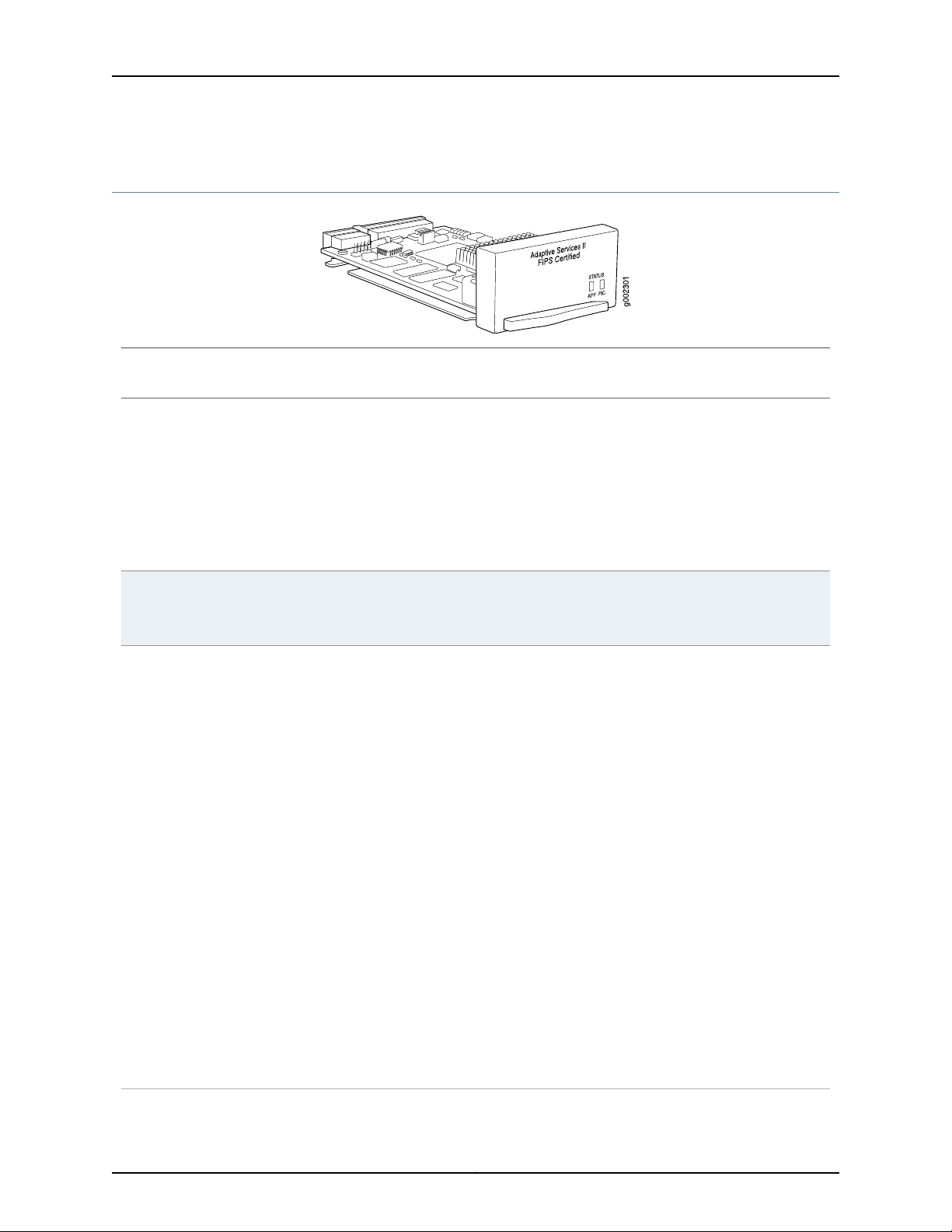
Adaptive Services II FIPS PIC (M7i Router)
•
Junos OS Release 7.2 and laterSoftware release
•
Description
Junos-FIPS requires an Adaptive Services II FIPS PIC for external IPSec connections. See the
Secure Configuration Guide for Common Criteria and Junos-FIPS for more information.
•
Supports tunnel services. This feature is included with the PIC and does not require an individual
license.
•
Individual licenses must be purchased for additional services such as Network Address
Translation(NAT), stateful firewall, intrusion detection services (IDS), IPSec. J-Flow accounting,
and voice services. For information about which services are supported by PIC and platform
type, see the Junos OS Services Interfaces Configuration Guide.
•
Power requirement: 0.4 A @ 48 V (19 W)
Hardware features
Software features
•
Support for up to 2000 service sets
•
Active monitoring on up to 1 million flows
•
Support for MTUs up to 9192 bytes for Gigabit Ethernet and SONET interfaces
For a list of the software features available for services PICs, see the Junos OS Services Interfaces
Configuration Guide.
Depending on your Junos OS Release and individual licenses, software features for this PIC can
include:
•
Stateful firewall with packet inspection:
•
Detects SYN attacks, ICMP and UDP floods, and ping-of-death attacks
•
NAT for IP addresses
•
Port Address Translation (PAT) for port numbers
•
J-Flow accounting exports cflowd version 5 and version 8 records
•
Tunnel services:
•
IP-IP unicast tunneling
•
GRE unicast tunneling—Supports GRE fragmentation
•
PIM sparse mode unicast tunneling
•
Virtual tunnel interface for Layer 3 VPNs
•
IPSec encryption
•
Voice services:
•
Compressed Real-Time Protocol (CRTP)
•
Encapsulations:
•
Multilink Frame Relay (MLFR)
•
Multilink Point-to-Point Protocol (MLPP)
Copyright © 2010, Juniper Networks, Inc.14
Page 15

Adaptive Services II FIPS PIC (M7i Router)
LEDs
Documentation
Related
Status LED, one tricolor:
•
Off—PIC is offline and it is safe to remove it from the chassis.
•
Green—PIC is operating normally.
•
Yellow—PIC is initializing.
•
Red—PIChas an error or failureand no further harm can be done by removing it from the chassis.
Application LED, one tricolor:
•
Off—Service is not running.
•
Green—Service is running under acceptable load.
•
Yellow—Service is overloaded.
M7i PICs Description on page 3•
• M7i PICs Supported on page 4
• M7i PIC/CFEB Compatibility on page 11
15Copyright © 2010, Juniper Networks, Inc.
Page 16
M7i Multiservice Edge Router PIC Guide
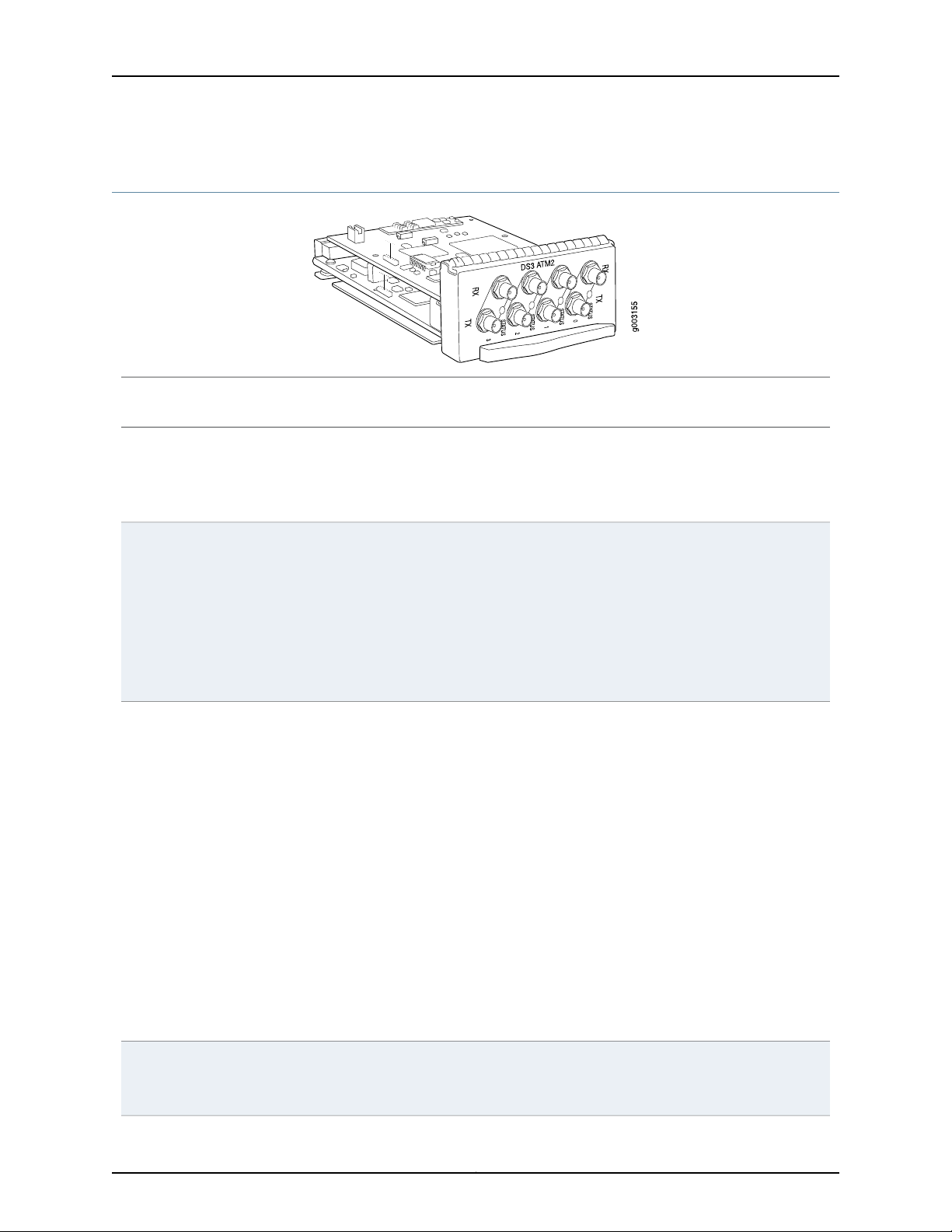
ATM2 DS3 IQ PIC (M7i Router)
•
Junos OS Release 6.1 and laterSoftware release
•
Description
Four DS3 ports
•
Power requirement: 0.41 A @ 48 V (20.0 W)
•
Intelligent queuing (IQ) PICs support fine-grained queuing per logical interface.
•
ATM standards compliant
Hardware features
Software features
•
16-MB SDRAM memory for ATM segmentation and reassembly (SAR)
•
ATM switch ID
•
Configurable framing options:
•
C-bit with ATM direct mapping
•
C-bit with Physical Layer Convergence Protocol (PLCP) framing (default)
•
M23 ATM direct mapping
•
M23 with PLCP framing
•
Internal and loop timing
•
Per-virtual circuit (VC) and per-virtual path (VP) traffic shaping
•
Unspecified bit rate (UBR) traffic shaping
•
Fine-grained variable bit rate (VBR) traffic shaping
•
Circuit cross-connect (CCC)
•
ATM Inverse Address Resolution Protocol (ARP), which enables routers to automatically learn
the IP address of the router on the far end of an ATM permanent virtual circuit (PVC)
•
Simple Network Management Protocol (SNMP):
•
Management Information Base (MIB) 2 (RFC 1213)
•
ATM MIB (RFC 1695)
•
SONET MIB
•
AAL5 encapsulations:
•
ATM-VC-MUX
•
ATM-NLPID
•
ATM-Cisco-LLPID
•
ATM-SNAP
•
ATM-CCC-VC-MUX
Cablesand connectors
Coaxial:
•
10 ft (3.05 m) posilock SMB to BNC (provided)
•
Four pairs of Rx and Tx coaxial cables
Copyright © 2010, Juniper Networks, Inc.16
Page 17

ATM2 DS3 IQ PIC (M7i Router)
LEDs
Alarms, errors, and
events
Related
Documentation
One tricolor per port:
•
Off—Not enabled
•
Green—Online with no alarms or failures
•
Yellow—Online with alarms for remote failures
•
Red—Active with a local alarm; router has detected a failure
•
Alarm indication signal (AIS)
•
Far-end block error (FEBE)
•
Frame error
•
Idle code
•
Idle received
•
Local and remote loopback
•
Loss of signal (LOS)
•
Out of frame (OOF)
•
Path parity error
•
Yellow alarm
M7i PICs Description on page 3•
• M7i PICs Supported on page 4
• M7i PIC/CFEB Compatibility on page 11
17Copyright © 2010, Juniper Networks, Inc.
Page 18
M7i Multiservice Edge Router PIC Guide
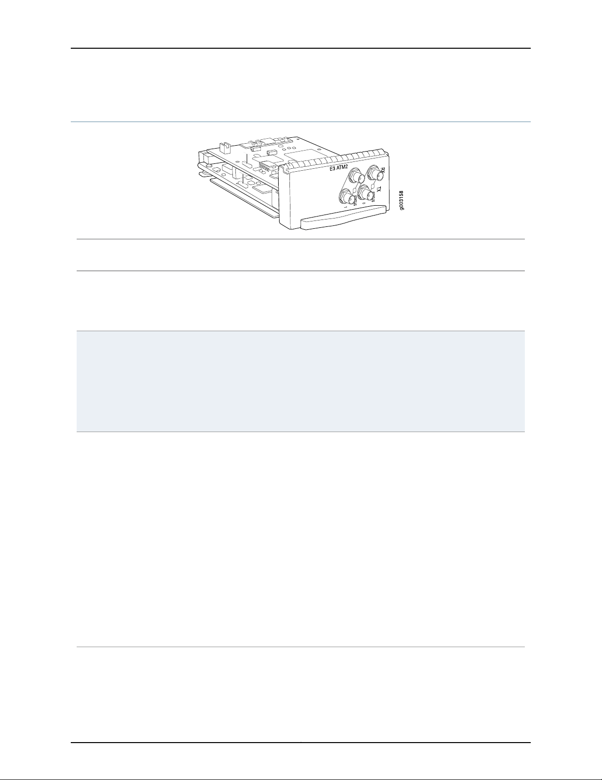
ATM2 E3 IQ PIC (M7i Router)
•
Junos OS Release 6.1 and laterSoftware release
•
Description
Two E3 ports
•
Power requirement: 0.41 A @ 48 V (20 W)
•
Intelligent queuing (IQ) PICs support fine-grained queuing per logical interface
•
ATM standards compliant
Hardware features
Software features
•
16-MB SDRAM memory for ATM segmentation and reassembly (SAR)
•
ATM switch ID
•
Configurable framing options:
•
G.751 direct mapping
•
G.751 with PLCP encapsulation (default)
•
G.832 ATM direct mapping
•
Internal and loop timing
•
Per-virtual circuit (VC) and per-virtual path (VP) traffic shaping
•
Unspecified bit rate (UBR) traffic shaping
•
Fine-grained variable bit rate (VBR) traffic shaping
•
Circuit cross-connect (CCC)
•
ATM Inverse Address Resolution Protocol (ARP), which enables routers to automatically learn
the IP address of the router on the far end of an ATM permanent virtual circuit (PVC)
•
Simple Network Management Protocol (SNMP):
•
Management Information Base (MIB) 2 (RFC 1213)
•
ATM MIB (RFC 1695)
•
SONET MIB
•
AAL5 encapsulations:
•
ATM-VC-MUX
•
ATM-NLPID
•
ATM-Cisco-LLPID
•
ATM-SNAP
•
ATM-CCC-VC-MUX
Copyright © 2010, Juniper Networks, Inc.18
Page 19

Cablesand connectors
ATM2 E3 IQ PIC (M7i Router)
•
10 ft (3.05 m) posilock SMB to BNC (provided)
•
Four pairs of Rx and Tx coaxial cables
•
SONET/SDH OC3/STM1 fixed transceiver:
•
Multimode
•
Intermediate reach (IR-1)
Optical interface specifications—see SONET/SDH OC3/STM1 Optical Interface Specifications
LEDs
Alarms, errors, and
events
Related
Documentation
One tricolor per port:
•
Off—Not enabled
•
Green—Online with no alarms or failures
•
Yellow—Online with alarms for remote failures
•
Red—Active with a local alarm; router has detected a failure
•
Alarm indication signal (AIS)
•
Frame error
•
Line code violation
•
Local and remote loopback
•
Loss of signal (LOS)
•
Out of frame (OOF)
•
Yellow alarm
M7i PICs Description on page 3•
• M7i PICs Supported on page 4
• M7i PIC/CFEB Compatibility on page 11
19Copyright © 2010, Juniper Networks, Inc.
Page 20

M7i Multiservice Edge Router PIC Guide
ATM2 OC3/STM1 IQ PIC (M7i Router)
•
Junos OS Release 6.0 and laterSoftware release
•
Description
Two OC3 ports
•
Power requirement: 0.41 A @ 48 V (20 W)
•
Intelligent queuing (IQ) PICs support fine-grained queuing per logical interface
•
Conforms to ANSI T1.105-1991 and T1E1.2/93-020R1
•
ATM and SONET/SDH standards compliant
•
Alarm and event counting and detection
•
Compatible with well-known ATM switches
•
ATM switch ID, which displays the switch IP address and local interface name of the adjacent
Fore ATM switches
Hardware features
Software features
•
Single 3010 SAR for segmentation and reassembly into 53 byte ATM cells
•
High-performance parsing of SONET/SDH frames
•
ASIC-basedpacketsegmentationand reassembly(SAR) management and output port queuing
•
64 MB SDRAM memory for ATM SAR
•
Packet buffering, Layer 2 parsing
•
Circuit cross-connect (CCC) for leveraging ATM access networks
•
User-configurable virtual circuit (VC) and virtual path (VP) support
•
Support for idle cell or unassigned cell transmission
•
OAM fault management processes alarm indication signal (AIS), remote defect indicator (RDI)
cells, and loop cells
•
Point-to-point and point-to-multipoint mode Layer 2 counters per VC and per VP
•
Local and remote loopback
•
ATM Inverse Address Resolution Protocol (ARP), which enables routers to automatically learn
the IP address of the router on the far end of an ATM permanent virtual circuit (PVC)
•
Simple Network Management Protocol (SNMP):
•
Management Information Base (MIB) 2 (RFC 1213)
•
ATM MIB (RFC 1695)
•
SONET MIB
•
Unspecified bit rate (UBR), non-real-time variable bit rate (VBR), and constant bit rate (CBR)
traffic shaping
•
Per-VC or per-VP traffic shaping
•
Support for F4 OAM cells
•
Support for 16 bit VCI range
Copyright © 2010, Juniper Networks, Inc.20
Page 21

Cablesand connectors
ATM2 OC3/STM1 IQ PIC (M7i Router)
•
Duplex SC/PC connector (RX and TX)
•
SONET/SDH OC3/STM1 fixed transceivers:
•
Multimode
•
Intermediate reach (IR-1)
Optical interface specifications—see SONET/SDH OC3/STM1 Optical Interface Specifications
LEDs
Alarms, errors, and
events
Related
Documentation
One tricolor per port:
•
Off—Not enabled
•
Green—Online with no alarms or failures
•
Yellow—Online with alarms for remote failures
•
Red—Active with a local alarm; router has detected a failure
•
Alarm indication signal (AIS-L, AIS-P)
•
Bit error rate signal degrade (BERR-SD), bit error rate signal fail (BERR-SF)
•
Bit interleaved parity errors B1, B2, B3
•
Errored seconds (ES-S, ES-L, ES-P), far-end bit errors REI-L, REI-P (CV-LFE, CV-PFE), far-end
errored seconds (ES-LFE, ES-PFE), far-end severely errored seconds (SES-LFE, SES-PFE),
far-end unavailable seconds (UAS-LFE, UAS-PFE)
•
Loss of cell delineation (LOC), loss of frame (LOF), loss of pointer (LOP-P), loss of signal (LOS)
•
Payload mismatch (PLM-P), payload unequipped (UNEQ-P)
•
Remote defect indication (RDI-L, RDI-P)
•
Severely errored framing (SEF), severely errored framing seconds (SEFS-S), severely errored
seconds (SES-S, SES-L, SES-P), unavailable seconds (UAS-L, UAS-P)
M7i PICs Description on page 3•
• M7i PICs Supported on page 4
• M7i PIC/CFEB Compatibility on page 11
• SONET/SDH OC3/STM1 Optical Interface Specifications
21Copyright © 2010, Juniper Networks, Inc.
Page 22
M7i Multiservice Edge Router PIC Guide
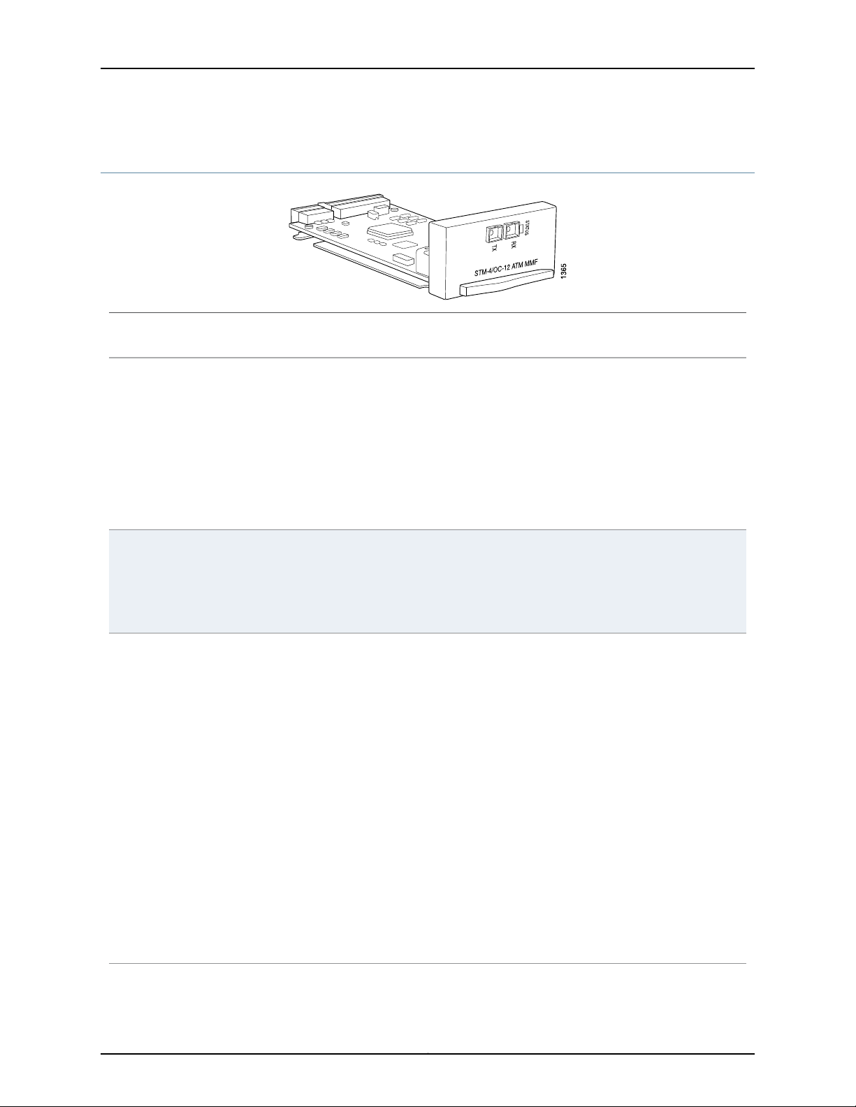
ATM2 OC12/STM4 IQ PIC (M7i Router)
•
Junos OS Release 6.0 and laterSoftware release
•
Description
One OC12 port
•
Power requirement: 0.41 A @ 48 V (20 W)
•
Intelligent queuing (IQ) PICs support fine-grained queuing per logical interface
•
Conforms to ANSI T1.105-1991 and T1E1.2/93-020R1
•
Complies with ATM and SONET/SDH standards
•
Alarm and event counting and detection
•
Compatible with well-known ATM switches
•
ATM switch ID, which displays the switch IP address and local interface name of the adjacent
Fore ATM switches
Hardware features
Software features
•
One 3010 SAR for segmentation and reassembly into 53-byte ATM cells
•
High-performance parsing of SONET/SDH frames
•
ASIC-basedpacketsegmentationand reassembly(SAR) management and output port queuing
•
64 MB SDRAM memory for ATM SAR
•
Packet buffering, Layer 2 parsing
•
Circuit cross-connect for leveraging ATM access networks
•
User-configurable virtual circuit (VC) and virtual path (VP) support
•
Support for idle cell or unassigned cell transmission
•
OAM fault management processes alarm indication signal (AIS), remote defect indication
(RDI), and loop cells
•
Point-to-point and point-to-multipoint mode Layer 2 counters per VC and per VP
•
Local and remote loopback
•
ATM Inverse ARP, which enables routers to automatically learn the IP address of the router on
the far end of an ATM PVC
•
Simple Network Management Protocol (SNMP):
•
Management Information Base (MIB) 2 (RFC 1213)
•
ATM MIB (RFC 1695)
•
SONET MIB
•
Unspecified bit rate (UBR), non-real-time variable bit rate (VBR), and constant bit rate (CBR)
traffic shaping
•
Per-VC or per-VP traffic shaping
•
Support for F4 OAM cells
•
Support for 16-bit VCI range
Copyright © 2010, Juniper Networks, Inc.22
Page 23

Cablesand connectors
ATM2 OC12/STM4 IQ PIC (M7i Router)
•
Duplex SC/PC connector (Rx and Tx)
•
SONET/SDH OC12/STM4 fixed transceivers:
•
Multimode
•
Intermediate reach (IR-1)
Optical interfacespecifications—seeSONET/SDH OC12/STM4Optical InterfaceSpecifications
LEDs
Alarms, errors, and
events
Related
Documentation
One tricolor per port:
•
Off—Not enabled
•
Green—Online with no alarms or failures
•
Yellow—Online with alarms for remote failures
•
Red—Active with a local alarm; router has detected a failure
•
Alarm indication signal (AIS-L, AIS-P)
•
Bit error rate signal degrade (BERR-SD), bit error rate signal fail (BERR-SF)
•
Bit interleaved parity errors B1, B2, B3
•
Errored seconds (ES-S, ES-L, ES-P), far-end bit errors REI-L, REI-P (CV-LFE, CV-PFE), far-end
errored seconds (ES-LFE, ES-PFE), far-end severely errored seconds (SES-LFE, SES-PFE),
far-end unavailable seconds (UAS-LFE, UAS-PFE)
•
Loss of cell delineation (LOC), loss of frame (LOF), loss of pointer (LOP-P), loss of signal (LOS)
•
Payload mismatch (PLM-P), payload unequipped (UNEQ-P)
•
Remote defect indication (RDI-L, RDI-P)
•
Severely errored framing (SEF), severely errored framing seconds (SEFS-S), severely errored
seconds (SES-S, SES-L, SES-P), unavailable seconds (UAS-L, UAS-P)
M7i PICs Description on page 3•
• M7i PICs Supported on page 4
• M7i PIC/CFEB Compatibility on page 11
• SONET/SDH OC12/STM4 Optical Interface Specifications
23Copyright © 2010, Juniper Networks, Inc.
Page 24
M7i Multiservice Edge Router PIC Guide
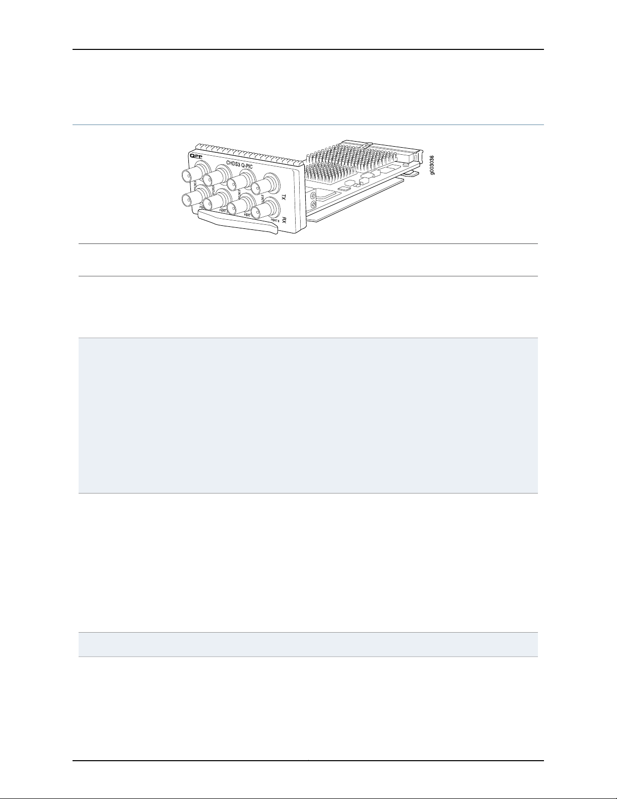
Channelized DS3 IQ PIC (M7i Router)
•
Junos OS Release 6.0 and laterSoftware release
•
Description
Four DS3 ports
•
Power requirement: 0.32 A @ 48 V (15.6 W)
•
Intelligent queuing (IQ) PICs support fine-grained queuing per logical interface
•
Channelization: DS3, DS0
Hardware features
Software features
•
Data service unit (DSU) functionality
•
Subrate and scrambling:
•
Digital Link/Quick Eagle
•
Kentrox
•
Larscom
•
ADTRAN
•
Verilink
•
B3ZS line encoding
•
M13 or C-bit parity
•
Full bit error rate test (BERT)
•
Local and remote loopback testing
•
Quality of service (QoS) per channel: weighted round-robin (WRR), random early detection
(RED), weighted random early detection (WRED)
•
Simple Network Management Protocol (SNMP): DS1 MIB, DS3 MIB
•
Dynamic, arbitrary channel configuration
•
Encapsulations:
•
High-Level Data Link Control (HDLC)
•
Frame Relay
•
Circuit cross-connect (CCC)
•
Translational cross-connect (TCC)
•
Point-to-Point Protocol (PPP)
•
Standard DS3 BNC coaxial cable interfacesCablesand connectors
Copyright © 2010, Juniper Networks, Inc.24
Page 25

Channelized DS3 IQ PIC (M7i Router)
LEDs
Alarms, errors, and
events
(counters)
Related
Documentation
One tricolor per port:
•
Off—Not enabled
•
Green—Online with no alarms or failures
•
Yellow—Online with alarms for remote failures
•
Red—Active with a local alarm; router has detected a failure
•
Alarm indication signal (AIS)
•
Excessive zeros (EXZ)
•
Far-end block error (FEBE)
•
Frame error
•
Idle code, Idle received
•
Line code violation (LCV)
•
Loss of signal (LOS)
•
Out of frame (OOF)
•
Parity bit (P-bit) disagreements
•
Path parity error
•
Yellow alarm bit (X-bit) disagreements
•
Layer 2 per-queue and per-channel packet and byte countersInstrumentation
M7i PICs Description on page 3•
• M7i PICs Supported on page 4
• M7i PIC/CFEB Compatibility on page 11
25Copyright © 2010, Juniper Networks, Inc.
Page 26

RX
RX
RX
RX
TX
TX
TX
TX
PO
RT
0
PO
RT
1
PO
RT
2
PO
RT
3
g006017
M7i Multiservice Edge Router PIC Guide
Channelized DS3 and E3 Enhanced IQ (IQE) PIC (M7i Router)
•
Junos OS Release 10.2 and later (Type 1)Software release
•
Description
Four E3 or Channelized DS3 ports
•
E3 or Channelized DS3 is configurable on a per-port granularity
•
DS3 channelization:
•
4 DS3 channels
•
112 DS1 channels
•
1011 DS0 channels
•
Power requirement: 0.53 A @ 48 V (25.4 W)
•
Ports are numbered 0 through 3 from left to rightHardware features
Software features
•
Maximum transmission units (MTUs) of up to 9000 bytes
•
Dynamic, arbitrary channel configuration
•
Subrate and scrambling:
NOTE: Only DS3 interfaces support subrate and scrambling.
•
Digital Link/Quick Eagle
•
Kentrox
•
Larscom
•
ADTRAN
•
Verilink (subrate: only port A mode)
NOTE: For DS3 interfaces, Verilink does not function if an IQE interface is paired with an IQ
interface.
•
Data service unit (DSU) functionality
•
B3ZS line encoding
•
Framing: M13, C-bit parity, framed clear channel
•
Full bit error rate test (BERT) for DS0, DS1, and DS3
•
ANSI T1.403 FDL
•
Internal and loop clocking for DS3 and DS1
•
DS3 far end alarm and control (FEAC) channel
•
Local line, remote line, and remote playback loopback testing for each DS3 and DS1channels
•
Quality of service (QoS) per channel: weighted round-robin (WRR), random early detection
(RED), weighted random early detection (WRED)
•
Enhanced fine-grained queuing per logical interface. See the Junos OS Class of Service
Configuration Guide for more information about class of service features.
•
Simple Network Management Protocol (SNMP): DS1 MIB, DS3 MIB
Copyright © 2010, Juniper Networks, Inc.26
Page 27

Channelized DS3 and E3 Enhanced IQ (IQE) PIC (M7i Router)
•
Encapsulations:
•
Circuit cross-connect (CCC)
•
Translational cross-connect (TCC)
•
Extended Frame Relay for CCC and TCC
•
Flexible Frame Relay
•
Frame Relay
•
Frame Relay for CCC
•
Frame Relay for TCC
•
Frame Relay port CCC
•
High-Level Data Link Control (HDLC)
•
HDLC framing for CCC
•
HDLC framing for TCC
•
MPLS CCC
•
MPLS TCC
•
Multilink Frame Relay (MLFR) UNI NNI (MFR FRF.16)
•
Point-to-Point Protocol (PPP)
•
PPP for CCC
•
PPP for TCC
LEDs
•
Standard DS3 BNC coaxial cable interfacesCablesand connectors
One tricolor per port:
•
Off—Not enabled
•
Green—Online with no alarms or failures
•
Yellow—Online with alarms for remote failures
•
Red—Active with a local alarm; router has detected a failure
27Copyright © 2010, Juniper Networks, Inc.
Page 28

M7i Multiservice Edge Router PIC Guide
•
Alarms, errors, and
events
Alarm reporting for error statistics and failure counts
•
DS1 alarms:
•
•
•
•
DS1 error detection:
•
•
•
•
•
•
•
•
•
•
DS3 alarms:
Alarm indication signal (AIS)
Loss of frame (LOF)
Remote alarm indication signal (RAIS)
Bursty errored seconds (BES)
CRC errors
Errored seconds (ES)
Line errored seconds (LES)
Loss of framing seconds (LOFS)
Loss of signal seconds (LOSS)
Severely errored seconds (SES)
Severely errored framing seconds (SEFS)
Unavailable seconds (UAS)
(counters)
•
Alarm indication signal (AIS)
•
Loss of frame (LOF)
•
Loss of signal (LOS)
•
Phase lock loop (PLL)
•
DS3 error detection:
•
C-bit code violations (CCV)
•
C-bit errored seconds (CES)
•
C-bit severely errored framing seconds (CEFS)
•
CRC errors
•
Excessive zeros (EXZ)
•
Far-end block error (FEBE)
•
Far-end receive failure (FERF)
•
Line errored seconds (LES)
•
Parity bit (P-bit) code violations (PCV)
•
Parity bit (P-bit) errored seconds (PES)
•
Parity bit (P-bit) severely errored framing seconds (PSES)
•
Severely errored framing seconds (SEFS)
•
Unavailable seconds (UAS)
•
Layer 2 per-queue and per-channel packet and byte countersInstrumentation
Related
Documentation
M7i PICs Description on page 3•
• M7i PICs Supported on page 4
• M7i PIC/CFEB Compatibility on page 11
Copyright © 2010, Juniper Networks, Inc.28
Page 29
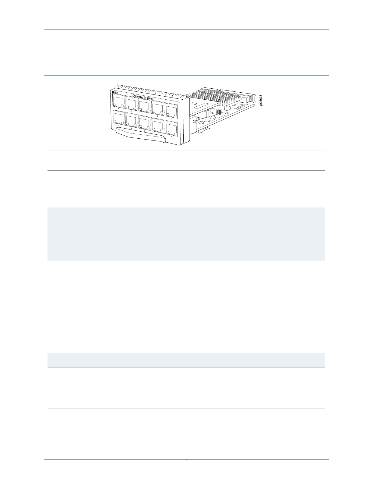
Channelized E1 IQ PIC (M7i Router)
•
PE-10CHE1-RJ48-QPP-N: Junos OS Release 9.1R4, 9.2R3, 9.3R1 and laterSoftware release
•
Description
Ten E1 ports
•
Power requirement: 0.15 A @ 48 V (7.2 W)
•
Intelligent queuing (IQ) PICs support fine-grained queuing per logical interface.
•
Channelization: E1, DS0
Channelized E1 IQ PIC (M7i Router)
Hardware features
Software features
LEDs
•
Data service unit (DSU) functionality
•
Ports configurable as clear channel E1 interfaces with 2.048-Mbps connectivity
•
Supports unframed E1 G.703 and G.704 framing modes
•
Supports HDB3 line coding
•
CRC4 configurable
•
Local and remote loopback testing
•
Quality of service (QoS) per channel: weighted round-robin (WRR), random early detection
(RED), weighted random early detection (WRED)
•
Simple Network Management Protocol (SNMP): E1 MIB, DS0 MIB
•
Dynamic, arbitrary channel configuration
•
Full bit error rate test (BERT)
•
Encapsulations:
•
High-Level Data Link Control (HDLC)
•
Frame Relay
•
Circuit cross-connect (CCC)
•
Translational cross-connect (TCC)
•
Point-to-Point Protocol (PPP)
•
120-ohm RJ-48CCables and connectors
One bicolor per E1 port:
•
Off—Port not enabled
•
Green—Physical E1 link is up; individual subchannels can be down
•
Red—Physical E1 link is down
29Copyright © 2010, Juniper Networks, Inc.
Page 30

M7i Multiservice Edge Router PIC Guide
•
Alarms, errors, and
events
Alarm indication signal (AIS)
•
Loss of frame (LOF)
•
Out of frame (OOF)
•
Failed signal rate (FSR)
•
Layer 2 per-queue and per-channel packet and byte countersInstrumentation
(counters)
Related
Documentation
M7i PICs Description on page 3•
• M7i PICs Supported on page 4
• M7i PIC/CFEB Compatibility on page 11
Copyright © 2010, Juniper Networks, Inc.30
Page 31

g006020
Channelized E1/T1 Enhanced IQ (IQE) PIC (M7i Router)
Channelized E1/T1 Enhanced IQ (IQE) PIC (M7i Router)
•
Junos OS Release 10.2 and later (Type 1)Software release
•
Description
Ten E1 or T1 ports
•
DS1 and E1 interfaces are selectable on a per-port granularity
•
E1 channelization per PIC:
•
10 E1 channels
•
310 DS0 channels
•
T1 channelization per PIC:
•
10 T1 channels
•
240 DS0 channels
•
Power requirement: 0.52 A @ 48 V (24.73 W)
Hardware features
Software features
•
Top row: 1, 3, 5, 7, and 9 from left to right
•
Bottom row: 0, 2, 4, 6, and 8 from left to right
•
Quality of service (QoS) per channel: weighted round-robin (WRR), random early detection
(RED), weighted random early detection (WRED)
•
Enhanced fine-grained queuing per logical interface. See the Junos OS Class of Service
Configuration Guide for more information about class of service features.
•
Support sending and receiving in-band loopback codes in both framed and unframed mode:
•
Framed in-band loopback at CSU
•
Framed in-band loopback at Smartjack (ANSI)
•
Unframed in-band loopback at CSU
•
Unframed in-band loopback at Smartjack (ANSI)
•
You can configure the following framing modes using the CLI:
•
T1—SF (D4/superframe), ESF (extended superframe)
•
E1—G704, G704–no-crc4, unframed
•
Packet buffering, Layer 2 parsing
•
Local line, remote line, and remote payload loopback testing; each channel can be looped
individually and independently of other channels (DS1/E1 channels)
•
Simple Network Management Protocol (SNMP): T1 MIB (RFC 1406)
•
Dynamic, arbitrary channel configuration
•
Full bit error rate test (BERT)
•
Clocking: internal and loop (clock recovered from network and use for transmit). Internal timing
is the default for channelized T1 ports. The external master clock can be a multiple of 2.048
MHz or 1.544 MHz for E1 or T1 operation.
•
Line coding:
31Copyright © 2010, Juniper Networks, Inc.
Page 32

M7i Multiservice Edge Router PIC Guide
•
•
•
Encapsulations:
•
•
•
•
•
•
•
•
•
•
•
•
•
•
•
•
•
Encapsulations available only for DS0 and DS1:
•
•
•
•
Encapsulations available only for DS1:
T1—CLI configurable as AMI or B8ZS
E1—HDB3
Circuit cross-connect (CCC)
Translational cross-connect (TCC)
Extended Frame Relay for CCC and TCC
Flexible Frame Relay
Frame Relay
Frame Relay for CCC
Frame Relay for TCC
Frame Relay port CCC
High-Level Data Link Control (HDLC)
HDLC framing for CCC
HDLC framing for TCC
MPLS CCC
MPLS TCC
Point-to-Point Protocol (PPP)
PPP for CCC
PPP for TCC
Multilink Frame Relay end-to-end (MLFR FRF.15)
Multilink Frame Relay (MLFR) UNI NNI (MFR FRF.16)
Multilink PPP (MLPPP)
LEDs
•
PPP over Frame Relay
•
120-ohm RJ-48C connector (female)Cablesand connectors
One tricolor per port:
•
Off—Not enabled
•
Green—Online with no alarms or failures
•
Yellow—Online with alarms for remote failures
•
Red—Active with a local alarm; router has detected a failure
Copyright © 2010, Juniper Networks, Inc.32
Page 33

Alarms, errors, and
events
Channelized E1/T1 Enhanced IQ (IQE) PIC (M7i Router)
•
DS1 alarms:
•
Alarm indication signal (AIS)
•
Loss of frame (LOF)
•
Remote alarm indication signal (RAIS)
•
24-hour alarm reporting history maintained for error statistics and failure counts, 15-minute
intervals on all errors
•
DS1 error detection:
•
Bursty errored seconds (BES)
•
CRC errors
•
Errored seconds (ES)
•
Line errored seconds (LES)
•
Loss of framing seconds (LOFS)
•
Loss of signal seconds (LOSS)
•
Severely errored seconds (SES)
•
Severely errored framing seconds (SEFS)
•
Unavailable seconds (UAS)
Instrumentation
(counters)
Related
Documentation
•
Layer 2 per-queue and per-channel packet and byte counters
•
Layer 2 per-queue and per-channel packet and byte drop counters
M7i PICs Description on page 3•
• M7i PICs Supported on page 4
• M7i PIC/CFEB Compatibility on page 11
33Copyright © 2010, Juniper Networks, Inc.
Page 34

M7i Multiservice Edge Router PIC Guide
Channelized OC3 IQ PIC (M7i Router)
•
Junos OS Release 7.6 and laterSoftware release
•
Description
One OC3 port
•
Power requirement: 0.39 A @ 48 V (18.6 W)
•
Fine-grained queuing per logical interface
•
Channelization: DS3, DS1, DS0
Hardware features
Software features
•
Subrate and scrambling:
•
Digital Link/Quick Eagle
•
Kentrox
•
Larscom
•
ADTRAN
•
Verilink
•
Packet buffering, Layer 2 parsing
•
M13/C-bit parity encoding
•
DS3 far-end alarm and control (FEAC) channel support
•
Local and remote loopback testing
•
Quality of service (QoS) per channel: weighted round-robin (WRR), random early detection
(RED), weighted random early detection (WRED)
•
Simple Network Management Protocol (SNMP): OC3 MIB, DS3 MIB, T1 MIB
•
Dynamic, arbitrary channel configuration
•
Full bit error rate test (BERT)
•
Encapsulations:
•
High-Level Data Link Control (HDLC)
•
Frame Relay
•
Circuit cross-connect (CCC)
•
Translational cross-connect (TCC)
•
Point-to-Point Protocol (PPP)
Cablesand connectors
•
Duplex SC/PC connector (Rx and Tx); single-mode fiber intermediate-reach fiber
•
SONET/SDH OC3/STM1 fixed transceivers:
•
Intermediate reach (IR-1)
Optical interface specifications—see SONET/SDH OC3/STM1 Optical Interface Specifications
Copyright © 2010, Juniper Networks, Inc.34
Page 35

Channelized OC3 IQ PIC (M7i Router)
LEDs
Alarms, errors, and
events
One tricolor per port:
•
Off—Not enabled
•
Green—Online with no alarms or failures
•
Yellow—Online with alarms for remote failures
•
Red—Active with a local alarm; router has detected a failure
•
Alarm indication signal (AIS-L, AIS-P)
•
Bit error rate signal degrade (BERR-SD), bit error rate signal fail (BERR-SF)
•
Bit interleaved parity errors B1, B2, B3
•
Errored seconds (ES-S, ES-L, ES-P), far-end bit errors REI-L, REI-P (CV-LFE, CV-PFE), Far-end
block error (FEBE), far-end errored seconds (ES-LFE, ES-PFE), far-end severely errored seconds
(SES-LFE, SES-PFE), far-end unavailable seconds (UAS-LFE, UAS-PFE)
•
Frame error
•
Idle code, Idle received
•
Loss of frame (LOF), loss of pointer (LOP-P), loss of signal (LOS)
•
Out of frame (OOF)
•
Payload mismatch (PLM-P), payload unequipped (UNEQ-P)
•
Parity bit (P-bit) disagreements
•
Path parity error
•
Remote defect indication (RDI-L, RDI-P)
•
Severely errored framing (SEF), severely errored framing seconds (SEFS-S), severely errored
seconds (SES-S, SES-L, SES-P), unavailable seconds (UAS-L, UAS-P)
•
Yellow alarm bit (X-bit) disagreements
Related
Documentation
M7i PICs Description on page 3•
• M7i PICs Supported on page 4
• M7i PIC/CFEB Compatibility on page 11
• SONET/SDH OC3/STM1 Optical Interface Specifications
35Copyright © 2010, Juniper Networks, Inc.
Page 36

M7i Multiservice Edge Router PIC Guide
Channelized OC3/STM1 Circuit Emulation PIC with SFP (M7i Router)
•
Junos OS Release 9.3 and laterSoftware release
•
Description
Four OC3/STM1 ports
•
Power requirement: 0.52 A @ 48 V (25 W)
•
Channelization: DS1
Channelization down to E1/T1
Each port can be channelized as 84 T1 ports for a total of 336 T1 pseudowires or 63 E1 ports
for a total of 252 pseudowires.
Hardware features
•
Subrate and scrambling:
•
Digital Link/Quick Eagle
•
Kentrox
•
Larscom
•
ADTRAN
•
Verilink
•
M13/C-bit parity encoding
•
Local and remote loopback testing
Copyright © 2010, Juniper Networks, Inc.36
Page 37

Software features
Channelized OC3/STM1 Circuit Emulation PIC with SFP (M7i Router)
•
Loop timing
•
Optical diagnostics
•
AM1 or B8ZS line encoding
•
APS/SDH MSP
•
Fractional mode and framed clear channel mode
•
Superframe (D4/SF) and extended superframe (ESP) framing
•
Simple Network Management Protocol (SNMP):
•
OC3 MIB
•
T1 MIB
•
ATM MIB (Junos OS Release 10.2 and later)
•
Automatic protection switching (APS)
•
Dynamic, arbitrary channel configuration
•
Full bit error rate test (BERT)
•
Encapsulations: Structure-agnostic time-division multiplexing (TDM) over packet (SAToP)
(RFC 4553)
•
Pseudowire emulation edge-to-edge (PWE3) for ATM (RFC 4717) (Junos OS Release 9.6 and
later)
•
ATM Pseudowire emulation edge-to-edge via dynamic labels (LDP, RSVP-TE) (Junos OS
Release 9.6 and later)
•
Inverse mulitplexing (IMA) for ATM (Junos OS Release 10.0 and later)
•
ATM QoS (Junos OS Release 10.2 and later):
•
Per-virtual circuit (VC) and per-virtual path (VP) traffic shaping
•
Unspecified bit rate (UBR) traffic shaping
•
Fine-grained real-time variable bit rate (rtVBR) and real-time variable bit rate (nrtVBR)
traffic shaping
•
Port-level egress shaping
•
Constant bit rate (CBR)
•
Policing on a per virtual circuit basis
•
Independent peak cell rate (PCR) and sustained cell rate (SCR) policing
•
Counting, tagging, or discard policing actions
Cablesand connectors
•
Duplex LC/PC connector (Rx and Tx)
•
SONET/SDH OC3/STM1 SFPs:
•
Multimode (model number: SFP-OC3-SR)
•
Intermediate reach (IR-1) (model number: SFP-OC3-IR)
•
Long reach (LR-1) (model number: SFP-OC3-LR)
Optical interface specifications—see SONET/SDH OC3/STM1 Optical Interface Specifications
37Copyright © 2010, Juniper Networks, Inc.
Page 38

M7i Multiservice Edge Router PIC Guide
LEDs
Alarms, errors, and
events
OK LED, one tricolor:
•
Off—PIC is offline and it is safe to remove it from the router.
•
Green—PIC is operating normally.
•
Yellow—PIC is initializing.
•
Red—PIC has an error or failure.
APP LED, one bicolor:
•
Off—Monitoring application is not running.
•
Green—Monitoring application is running under acceptable load.
One tricolor per port:
•
Off—Not enabled
•
Green—Online with no alarms or failures
•
Yellow—Online with alarms for remote failures
•
Red—Active with a local alarm; router has detected a failure
Structure agnostic alarms for T1 interface:
•
Alarm indication signal (AIS-L, AIS-P)
•
Loss of signal (LOS)
•
Errored seconds (ES)
•
Line-errored seconds (LES)
•
Severely errored seconds (SES)
•
Unavailable errored seconds (UAS)
•
Bipolar violation (BPV)
•
Controlled slip (CS)
•
Line code violation (LCV)
Structure agnostic alarms for E1 interface:
Related
Documentation
•
Alarm indication signal (AIS-L, AIS-P)
•
Loss of signal (LOS)
•
Errored seconds (ES)
•
Line-errored seconds (LES)
•
Severely errored seconds (SES)
•
Unavailable errored seconds (UAS)
•
Bipolar violation (BPV)
•
Controlled slip (CS)
•
Line code violation (LCV)
M7i PICs Description on page 3•
• M7i PICs Supported on page 4
• M7i PIC/CFEB Compatibility on page 11
• SONET/SDH OC3/STM1 Optical Interface Specifications
Copyright © 2010, Juniper Networks, Inc.38
Page 39

STATUS
PORT 1
PORT 0
TX
TX
RX
RX
g006019
Channelized OC3/STM1 Enhanced IQ (IQE) with SFP (M7i Router)
Channelized OC3/STM1 Enhanced IQ (IQE) with SFP (M7i Router)
•
Junos OS Release 10.2 and laterSoftware release
•
Description
Two OC3 or STM1 ports
•
SONET or SDH is configurable on a per-port granularity
•
SONET channelization:
•
2 OC3 channels
•
6 DS3 channels
•
168 DS1 channels
•
1011 DS0 channels
•
SDH channelization:
•
2 STM1 channels (non-concatenated)
•
6 E3 channels
•
126 E1 channels
•
6 DS3 channels
•
168 DS1 channels
•
1011 DS0 channels
•
Power requirement: 0.56 A @ 48 V (27.1 W)
•
Ports are numbered 0 and 1 from left to rightHardware features
39Copyright © 2010, Juniper Networks, Inc.
Page 40

M7i Multiservice Edge Router PIC Guide
•
Software features
Dynamic, arbitrary channel configuration
•
Quality of service (QoS) per channel: weighted round-robin (WRR), random early detection
(RED), weighted random early detection (WRED)
•
Enhanced fine-grained queuing per logical interface. See the Junos OS Class of Service
Configuration Guide for more information about class of service features.
•
Subrate and scrambling:
•
•
•
•
•
•
Packet buffering, Layer 2 parsing
•
M13/C-bit parity encoding
•
DS3 far-end alarm and control (FEAC) channel support
•
Local line, remote line, and remote payload loopback testing
•
Simple Network Management Protocol (SNMP): OC3 MIB, DS3 MIB, T1 MIB
•
Full bit error rate test (BERT)
•
Encapsulations:
Digital Link/Quick Eagle
Kentrox
Larscom
ADTRAN
Verilink
•
Circuit cross-connect (CCC)
•
Translational cross-connect (TCC)
•
Extended Frame Relay for CCC and TCC
•
Flexible Frame Relay
•
Frame Relay
•
Frame Relay for CCC
•
Frame Relay for TCC
•
Frame Relay port CCC
•
High-Level Data Link Control (HDLC)
•
HDLC framing for CCC
•
HDLC framing for TCC
•
MPLS CCC
•
MPLS TCC
•
Multilink Frame Relay (MLFR) UNI NNI (MFR FRF.16)
•
Point-to-Point Protocol (PPP)
•
PPP for CCC
•
PPP for TCC
•
Encapsulations available only for DS1:
•
Multilink Frame Relay end-to-end (MLFR FRF.15)
•
Multilink PPP (MLPPP)
•
PPP over Frame Relay
Cablesand connectors
•
Duplex LC/PC connector (Rx and Tx)
•
SONET/SDH OC3/STM1 SFPs:
•
Multimode (model number: SFP-OC3-SR)
•
Intermediate Reach (IR-1) (model number: SFP-OC3-IR)
•
Long reach (LR-1) (model number: SFP-OC3-LR)
Optical interface support—See SONET/SDH OC3/STM1 Optical Interface Specifications
Copyright © 2010, Juniper Networks, Inc.40
Page 41

Channelized OC3/STM1 Enhanced IQ (IQE) with SFP (M7i Router)
LEDs
Alarms, errors, and
events
One tricolor Status LED per port:
•
Off—Not enabled
•
Green—Online with no alarms or failures
•
Yellow—Online with alarms for remote failures
•
Red—Active with a local alarm; router has detected a failure
•
SONET alarms:
•
Alarm indication signal—line (AIS-L)
•
Alarm indication signal—path (AIS-P)
•
Bit error rate—signal degrade (BERR-SD)
•
Bit error rate—signal fail (BERR-SF)
•
Loss of clock (LOC)
•
Loss of frame (LOF)
•
Loss of light (LOL)
•
Loss of pointer (LOP)
•
Loss of signal (LOS)
•
Payload label mismatch (PLM-P)
•
Remote defect indication—line (RDI-L)
•
Remote defect indication—path (RDI-P)
•
Remote error indication (REI)
•
Payload unequipped (unequipped STS at path level) (UNEQ-P)
•
Virtual container—alarm indication signal (VAIS)
•
Virtual container—loss of clock (VLOC)
•
Virtual container—loss of pointer (VLOP)
•
Virtual container—mismatch (VMIS)
•
Virtual container—remote defect indication (VRD1)
•
Virtual container—unequipped (VUNEQ)
•
SDH alarms:
•
Administrative unit alarm indication signal (AU-AIS)
•
Bit error rate signal degrade (BERR-SD)
•
Bit error rate signal fail (BERR-SF)
•
Bit interleaved parity (BIP) error B1, B2, B3
•
Higher order path—alarm indication signal (HP-AIS)
•
Higher order path—far-end receiver error (HP-FERF)
•
Higher order path—payload label mismatch (HP-PLM)
•
Higher order path—loss of pointer (HP-LOP)
•
Higher order path—remote defect indication (HP-RDI)
•
Higher order path—unequipped (HP-UNEQ)
•
Loss of clock (LOC)
•
Loss of frame (LOF)
•
Loss of light (LOL)
•
Loss of signal (LOS)
•
Multiplex section—alarm indication signal (MS-AIS)
•
Multiplex section—far-end receive error (MS-FERF)
•
Multiplex section—remote defect indication (MS-RDI)
•
Multiplex section—remote error indication (MS-REI)
41Copyright © 2010, Juniper Networks, Inc.
Page 42

M7i Multiservice Edge Router PIC Guide
•
•
•
•
•
•
•
•
•
•
DS1 alarms:
•
•
•
•
DS1 error detection:
•
•
•
•
•
•
•
•
•
•
DS3 alarms:
Phase lock loop (PLL)
Remote error indication (REI)
Severely errored frame (SEF)
Tributary unit—alarm indication signal (TU-AIS)
Tributary unit—loss of clock (TU-LOC)
Tributary unit—loss of pointer (TU-LOP)
Tributary unit—mismatch (TU-MIS)
Tributary unit—remote defect indication (TU-RD1)
Tributary unit—unequipped (TU-UNEQ)
Alarm indication signal (AIS)
Loss of frame (LOF)
Remote alarm indication signal (RAIS)
Bursty errored seconds (BES)
CRC errors
Errored seconds (ES)
Line errored seconds (LES)
Loss of framing seconds (LOFS)
Loss of signal seconds (LOSS)
Severely errored seconds (SES)
Severely errored framing seconds (SEFS)
Unavailable seconds (UAS)
•
Alarm indication signal (AIS)
•
Loss of frame (LOF)
•
Loss of signal (LOS)
•
Phase lock loop (PLL)
•
DS3 error detection:
•
C-bit code violations (CCV)
•
C-bit errored seconds (CES)
•
C-bit severely errored framing seconds (CEFS)
•
CRC errors
•
Excessive zeros (EXZ)
•
Far-end block error (FEBE)
•
Far-end receive failure (FERF)
•
Line errored seconds (LES)
•
Parity bit (P-bit) code violations (PCV)
•
Parity bit (P-bit) errored seconds (PES)
•
Parity bit (P-bit) severely errored framing seconds (PSES)
•
Severely errored framing seconds (SEFS)
•
Unavailable seconds (UAS)
Copyright © 2010, Juniper Networks, Inc.42
Page 43

Channelized OC3/STM1 Enhanced IQ (IQE) with SFP (M7i Router)
Related
Documentation
M7i PICs Description on page 3•
• M7i PICs Supported on page 4
• M7i PIC/CFEB Compatibility on page 11
• SONET/SDH OC3/STM1 Optical Interface Specifications
43Copyright © 2010, Juniper Networks, Inc.
Page 44

M7i Multiservice Edge Router PIC Guide
Channelized OC12 IQ PIC (M7i Router)
•
Junos OS Release 6.1 and laterSoftware release
•
Description
One OC12 port
•
Power requirement: 0.23 A @ 48 V (10.8 W)
•
Intelligent queuing (IQ) PICs support fine-grained queuing per logical interface
•
Channelization: OC3, DS3, DS1, DS0
Hardware features
Software features
•
Subrate and scrambling:
•
Digital Link/Quick Eagle
•
Kentrox
•
Larscom
•
ADTRAN
•
Verilink
•
Packet buffering, Layer 2 parsing
•
M13/C-bit parity encoding
•
DS3 far-end alarm and control (FEAC) channel support
•
Local and remote loopback testing
•
Quality of service (QoS) per channel: weighted round-robin (WRR), random early detection
(RED), weighted random early detection (WRED)
•
Simple Network Management Protocol (SNMP): OC3 MIB, DS3 MIB, T1 MIB
•
Dynamic, arbitrary channel configuration
•
Full bit error rate test (BERT)
•
Encapsulations:
•
High-Level Data Link Control (HDLC)
•
Frame Relay
•
Circuit cross-connect (CCC)
•
Translational cross-connect (TCC)
•
Point-to-Point Protocol (PPP)
Cablesand connectors
•
Duplex SC/PC connector (Rx and Tx); single-mode fiber
•
SONET/SDH OC12/STM4 fixed transceiver:
•
Intermediate reach (IR-1)
Optical interfacespecifications—seeSONET/SDH OC12/STM4Optical InterfaceSpecifications
Copyright © 2010, Juniper Networks, Inc.44
Page 45

Channelized OC12 IQ PIC (M7i Router)
LEDs
Alarms, errors, and
events
One tricolor per port:
•
Off—Not enabled
•
Green—Online with no alarms or failures
•
Yellow—Online with alarms for remote failures
•
Red—Active with a local alarm; router has detected a failure
•
Alarm indication signal (AIS-L, AIS-P)
•
Bit error rate signal degrade (BERR-SD), bit error rate signal fail (BERR-SF)
•
Bit interleaved parity errors B1, B2, B3 (CV-S, CV-L, CV-P)
•
Errored seconds (ES-S, ES-L, ES-P), far-end bit errors REI-L, REI-P (CV-LFE, CV-PFE), far-end
block error (FEBE), far-end errored seconds (ES-LFE, ES-PFE), far-end severely errored seconds
(SES-LFE, SES-PFE), far-end unavailable seconds (UAS-LFE, UAS-PFE)
•
Frame error
•
Idle code, Idle received
•
Loss of frame (LOF), loss of pointer (LOP-P), loss of signal (LOS)
•
Out of frame (OOF)
•
Payload mismatch (PLM-P), payload unequipped (UNEQ-P)
•
Parity bit (P-bit) disagreements
•
Path parity error
•
Remote defect indication (RDI-L, RDI-P)
•
Severely errored framing (SEF), severely errored framing seconds (SEFS-S), severely errored
seconds (SES-S, SES-L, SES-P), unavailable seconds (UAS-L, UAS-P)
•
Yellow alarm bit (X-bit) disagreements
(counters)
Documentation
Related
•
Layer 2 per-queue and per-channel packet and byte countersInstrumentation
M7i PICs Description on page 3•
• M7i PICs Supported on page 4
• M7i PIC/CFEB Compatibility on page 11
• SONET/SDH OC12/STM4 Optical Interface Specifications
45Copyright © 2010, Juniper Networks, Inc.
Page 46

TX
RX
Channelized
STM-4/OC-12 SFP
g006014
M7i Multiservice Edge Router PIC Guide
Channelized OC12/STM4 Enhanced IQ (IQE) PIC with SFP (M7i Router)
Figure 1: 1-Port IQE PIC
•
Junos OS Release 10.2 and later (Type 1)Software release
•
Description
One OC12/STM4 port
•
SONET channelization:
•
1 OC12 channel
•
4 OC3 channels
•
12 DS3 channels
•
336 DS1 channels
•
1011 DS0 channels
•
SDH channelization:
•
1 STM4 channel
•
4 STM1 channels
•
12 E3 channels
•
252 E1 channels
•
12 DS3 channels
•
336 DS1 channels
•
1011 DS0 channels
•
Power requirement: 0.64 A @ –48 V (30.7 W)
•
Port is numbered 0.Hardware features
Copyright © 2010, Juniper Networks, Inc.46
Page 47

Software features
Channelized OC12/STM4 Enhanced IQ (IQE) PIC with SFP (M7i Router)
•
Quality of service (QoS) per channel: weighted round-robin (WRR), random early detection
(RED), weighted random early detection (WRED)
•
Enhanced fine-grained queuing per logical interface. See the Junos OS Class of Service
Configuration Guide for more information about class of service features.
•
Subrate and scrambling:
•
Digital Link/Quick Eagle
•
Kentrox
•
Larscom
•
ADTRAN
•
Verilink
•
Packet buffering, Layer 2 parsing
•
M13/C-bit parity encoding
•
DS3 far-end alarm and control (FEAC) channel support
•
Local line, remote line, and remote payload loopback testing
•
Simple Network Management Protocol (SNMP): OC3 MIB, DS3 MIB, T1 MIB
•
Dynamic, arbitrary channel configuration
•
Full bit error rate test (BERT)
NOTE: BERT is not applicable for SONET/SDH channels.
•
Encapsulations:
•
Circuit cross-connect (CCC)
•
Translational cross-connect (TCC)
•
Extended Frame Relay for CCC and TCC
•
Flexible Frame Relay
•
Frame Relay
•
Frame Relay for CCC
•
Frame Relay for TCC
•
Frame Relay port CCC
•
High-Level Data Link Control (HDLC)
•
HDLC framing for CCC
•
HDLC framing for TCC
•
MPLS CCC
•
MPLS TCC
•
Multilink Frame Relay (MLFR) UNI NNI (MFR FRF.16)
•
Point-to-Point Protocol (PPP)
•
PPP for CCC
•
PPP for TCC
•
Encapsulations available only for DS1:
•
Multilink Frame Relay end-to-end (MLFR FRF.15)
•
Multilink PPP (MLPPP)
•
PPP over Frame Relay
47Copyright © 2010, Juniper Networks, Inc.
Page 48

M7i Multiservice Edge Router PIC Guide
•
Cablesand connectors
Duplex LC/PC connector (Rx and Tx); single-mode fiber
•
SONET/SDH OC12/STM4 fiber-optic SFP transceivers:
•
•
•
Optical interfacespecifications—seeSONET/SDH OC12/STM4Optical InterfaceSpecifications
Short reach (model number: SFP-OC12-SR)
Intermediate reach (IR-1) (model number: SFP-OC312-IR)
Long reach (LR-1) (model number: SFP-OC12-LR)
LEDs
Alarms, errors, and
events
One tricolor per port:
•
Off—Not enabled
•
Green—Online with no alarms or failures
•
Yellow—Online with alarms for remote failures
•
Red—Active with a local alarm; router has detected a failure
•
SONET alarms:
•
Alarm indication signal—line (AIS-L)
•
Alarm indication signal—path (AIS-P)
•
Bit error rate—signal degrade (BERR-SD)
•
Bit error rate—signal fail (BERR-SF)
•
Loss of frame (LOF)
•
Loss of light (LOL)
•
Loss of pointer (LOP)
•
Loss of signal (LOS)
•
Payload label mismatch (PLM-P)
•
Remote defect indication—line (RDI-L)
•
Remote defect indication—path (RDI-P)
•
Remote error indication (REI)
•
Payload unequipped (unequipped STS at path level) (UNEQ-P)
•
Virtual container—alarm indication signal (VAIS)
•
Virtual container—loss of pointer (VLOP)
•
Virtual container—mismatch (VMIS)
•
Virtual container—remote defect indication (VRD1)
•
Virtual container—unequipped (VUNEQ)
•
SDH alarms:
•
Administrative unit alarm indication signal (AU-AIS)
•
Bit error rate—signal degrade (BERR-SD)
•
Bit error rate—signal fail (BERR-SF)
•
Bit interleaved parity (BIP) error B1, B2, B3
•
Higher order path—alarm indication signal (HP-AIS)
•
Higher order path—far-end receive failure (HP-FERF)
•
Higher order path—payload label mismatch (HP-PLM)
•
Higher order path—loss of pointer (HP-LOP)
•
Higher order path—remote defect indication (HP-RDI)
•
Higher order path—unequipped (HP-UNEQ)
•
Loss of frame (LOF)
•
Loss of light (LOL)
•
Loss of signal (LOS)
Copyright © 2010, Juniper Networks, Inc.48
Page 49

Channelized OC12/STM4 Enhanced IQ (IQE) PIC with SFP (M7i Router)
•
Multiplex section—alarm indication signal (MS-AIS)
•
Multiplex section—far-end receive failure (MS-FERF)
•
Multiplex section—remote defect indication (MS-RDI)
•
Multiplex section—remote error indication (MS-REI)
•
Phase lock loop (PLL)
•
Remote error indication (REI)
•
Severely errored frame (SEF)
•
Tributary unit—alarm indication signal (TU-AIS)
•
Tributary unit—loss of pointer (TU-LOP)
•
Tributary unit—mismatch (TU-MIS)
•
Tributary unit—remote defect indication (TU-RD1)
•
Tributary unit—unequipped (TU-UNEQ)
•
DS1 alarms:
•
Alarm indication signal (AIS)
•
Loss of frame (LOF)
•
Remote alarm indication signal (RAIS)
•
DS1 error detection:
•
Bursty errored seconds (BES)
•
CRC errors
•
Errored seconds (ES)
•
Line errored seconds (LES)
•
Loss of framing seconds (LOFS)
•
Severely errored seconds (SES)
•
Severely errored framing seconds (SEFS)
•
Unavailable seconds (UAS)
•
DS3 alarms:
•
Alarm indication signal (AIS)
•
Loss of frame (LOF)
•
Yellow alarm
•
DS3 error detection:
•
C-bit code violations (CCV)
•
C-bit errored seconds (CES)
•
C-bit severely errored framing seconds (CEFS)
•
CRC errors
•
Excessive zeros (EXZ)
•
Far-end block error (FEBE)
•
Far-end receive failure (FERF)
•
Line errored seconds (LES)
•
Parity bit (P-bit) code violations (PCV)
•
Parity bit (P-bit) errored seconds (PES)
•
Parity bit (P-bit) severely errored framing seconds (PSES)
•
Severely errored framing seconds (SEFS)
•
Unavailable seconds (UAS)
49Copyright © 2010, Juniper Networks, Inc.
Page 50

M7i Multiservice Edge Router PIC Guide
•
Layer 2 per-queue and per-channel packet and byte countersInstrumentation
(counters)
Related
Documentation
M7i PICs Description on page 3•
• M7i PICs Supported on page 4
• M7i PIC/CFEB Compatibility on page 11
Copyright © 2010, Juniper Networks, Inc.50
Page 51

Channelized STM1 IQ PIC (M7i Router)
•
Junos OS Release 6.0 and laterSoftware release
•
Description
Hardware features
One STM1 port
•
Power requirement: 0.39 A @ 48 V (18.6 W)
•
Intelligent queuing (IQ) PICs support fine-grained queuing per logical interface
•
Channelization: STM1c, fractional E1, framed and unframed DS0
•
Packet buffering, Layer 2 parsing
•
Local and remote loopback testing
Channelized STM1 IQ PIC (M7i Router)
Software features
LEDs
•
Quality of service (QoS) per channel: weighted round-robin (WRR), random early detection
(RED), weighted random early detection (WRED)
•
SNMP: SONET/SDH MIB, T1/E1 MIB
•
Dynamic, arbitrary channel configuration
•
Full bit error rate test (BERT) patterns at E1 and DS0 levels
•
Encapsulations:
•
High-Level Data Link Control (HDLC)
•
Frame Relay
•
Circuit cross-connect (CCC)
•
Translational cross-connect (TCC)
•
Point-to-Point Protocol (PPP)
•
Duplex SC/PC connector (Rx and Tx); single-mode intermediate-reach fiberCablesand connectors
One tricolor:
•
Off—Not enabled
•
Green—Online with no alarms or failures
•
Yellow—Online with alarms for remote failures
•
Red—Active with a local alarm; router has detected a failure
51Copyright © 2010, Juniper Networks, Inc.
Page 52

M7i Multiservice Edge Router PIC Guide
•
Alarms, errors, and
events
Alarm indication signal (AIS-L, AIS-P)
•
Bit error rate signal degrade (BERR-SD), bit error rate signal fail (BERR-SF)
•
Bit interleaved parity errors B1, B2, B3 (CV-S, CV-L, CV-P)
•
Errored seconds (ES-S, ES-L, ES-P), far-end bit errors REI-L, REI-P (CV-LFE, CV-PFE), far-end
errored seconds (ES-LFE, ES-PFE), far-end severely errored seconds (SES-LFE, SES-PFE),
far-end unavailable seconds (UAS-LFE, UAS-PFE)
•
Loss of frame (LOF), loss of pointer (LOP-P), loss of signal (LOS)
•
Payload mismatch (PLM-P), payload unequipped (UNEQ-P)
•
Remote defect indication (RDI-L, RDI-P)
•
Severely errored framing (SEF), severely errored framing seconds (SEFS-S), severely errored
seconds (SES-S, SES-L, SES-P), unavailable seconds (UAS-L, UAS-P)
•
Layer 2 per-queue and per-channel packet and byte countersInstrumentation
(counters)
Related
Documentation
M7i PICs Description on page 3•
• M7i PICs Supported on page 4
• M7i PIC/CFEB Compatibility on page 11
Copyright © 2010, Juniper Networks, Inc.52
Page 53

Channelized T1 IQ PIC (M7i Router)
•
Junos OS Release 7.4 and laterSoftware release
•
Description
Ten T1 ports
•
Power requirement: 0.15 A @ 48 V (7.2 W)
•
Intelligent queuing (IQ) PICs support fine-grained queuing per logical interface.
•
Channelization: T1, FT1, NxDS0
Channelized T1 IQ PIC (M7i Router)
Hardware features
•
Data service unit (DSU) and channel service unit (CSU) functionality
•
Ports configurable as clear channel T1 interfaces with 1.544-Mbps connectivity
•
Framing: Superframe (SF or D4) and Extended Superframe (ESF)
•
Supports B8ZS (bipolar 8-zero substitution) and AMI (alternate mark inversion) line coding
•
Local, remote, and payload loopback testing
•
ANSI T1.403 loopback support:
•
Respondstoembedded loopback commands upon receipt of an FDL command from remote
end with loopup and loopdown at both line and payload level
•
Insertion of loopback commands enables remote CSU/NIU/Smartjack to enter loopback
and loopdown at both the line and payload level (ANSI and Telcordia)
•
Inband loopback support:
•
Responds to inband loopback commands at both the line and payload level (ANSI and
Telcordia)
•
Insertion of inband loopback commands at both the line and payload level (ANSI and
Telcordia)
•
Clocking support of external (line) and internal
•
Buildout support of the following ranges:
•
0 through 132 (Line buildout is from 1 through 132 feet)
•
133 through 265 (Line buildout is from 133 through 265 feet)
•
266 through 398 (Line buildout is from 266 through 398 feet)
•
399 through 531 (Line buildout is from 399 through 531 feet)
•
532 through 655 (Line buildout is from 532 through 655 feet)
53Copyright © 2010, Juniper Networks, Inc.
Page 54

M7i Multiservice Edge Router PIC Guide
•
Software features
Quality of service (QoS) per channel: weighted round-robin (WRR), random early detection
(RED), weighted random early detection (WRED)
•
SNMP: T1 MIB and DS0 MIB
•
Dynamic, arbitrary channel configuration
•
Full bit error rate test (BERT) patterns at T1 and DS0 levels
•
Encapsulations:
•
•
•
•
•
•
120-ohm RJ-48C connector (female)Cablesand connectors
High-Level Data Link Control (HDLC)
Frame Relay
Circuit cross-connect (CCC)
Translational cross-connect (TCC)
Point-to-Point Protocol (PPP)
LEDs
Alarms, errors, and
events
Instrumentation
(counters)
Related
Documentation
One tricolor per port:
•
Off—Not enabled
•
Green—Online with no alarms or failures
•
Yellow—Online with alarms for remote failures
•
Red—Active with a local alarm; router has detected a failure
•
Alarm indication signal (AIS)
•
Remote defect indication (RDI)
•
Loss of frame (LOF)
•
Loss of signal (LOS)
•
Bipolar violation (BPV)
•
Excessive zero (EXZ)
•
Line code violation (LCV)
•
Error seconds (ES)
•
Severely errored seconds (SES)
•
Severely errored frames (SEF)
•
Bit error event (BEE)
•
Layer 2 per-queue and per-channel packet and byte counters
•
24–hour history or error counter updated at 15–minute intervals
M7i PICs Description on page 3•
• M7i PICs Supported on page 4
• M7i PIC/CFEB Compatibility on page 11
Copyright © 2010, Juniper Networks, Inc.54
Page 55

DS3 PIC (M7i Router)
•
Description
Hardware features
•
•
•
•
•
•
•
•
•
•
DS3 PIC (M7i Router)
Junos OS Release 6.0 and laterSoftware release
Two or four DS3 ports
Power requirement: 0.47 A @ 48 V (22.5 W)
Integrated DSU interoperability with leading DSU vendors
High-performance throughput on each port at speeds up to 44.736 Mbps, full duplex
C-bit framing
B3ZS line encoding
Subrate and scrambling:
•
Digital Link
•
Kentrox
•
Larscom
Per-port rate policing on input
Per-port rate shaping on output
Packet buffering, Layer 2 parsing
Software features
LEDs
•
DS3 functionality:
•
C-bit framing
•
B3ZS line encoding
•
DS3 diagnostics and loopback control
•
DS3 alarm and event counting and detection
•
Per-packet counts and byte counts
•
Local and remote loopback testing, as well as BERT testing per DS3
•
DS3 far-end alarm and control (FEAC) channel support
•
Encapsulations:
•
High-Level Data Link Control (HDLC)
•
Frame Relay
•
Circuit cross-connect (CCC)
•
Point-to-Point Protocol (PPP)
•
Custom 10 ft (3.05 m) posilock SMB to BNC male cable, separate Rx and Tx (provided)Cablesand connectors
One tricolor per port:
•
Off—Not enabled
•
Green—Online with no alarms or failures
•
Yellow—Online with alarms for remote failures
•
Red—Active with a local alarm; router has detected a failure
55Copyright © 2010, Juniper Networks, Inc.
Page 56

M7i Multiservice Edge Router PIC Guide
•
Alarms, errors, and
events
Alarm indication signal (AIS)
•
Bit error rate test (BERT) functionality on PIC (you can configure one DS3 channel in BERT
mode and configure the remaining channels to transmit and receive normal traffic)
•
Equipment failure (does not affect service)
•
Far-end block error (FEBE)
•
Frame error
•
Idle code, Idle received
•
Local and remote loopback
•
Loss of signal (LOS)
•
Out of frame (OOF)
•
Parity bit (P-bit) disagreements
•
Path parity error
•
Yellow alarm bit (X-bit) disagreements
Related
Documentation
M7i PICs Description on page 3•
• M7i PICs Supported on page 4
• M7i PIC/CFEB Compatibility on page 11
Copyright © 2010, Juniper Networks, Inc.56
Page 57

DS3/E3 Enhanced IQ (IQE) PIC (M7i Router)
RX
RX
RX
RX
TX
TX
TX
TX
PO
RT
0
PO
RT
1
PO
RT
2
PO
RT
3
DS3/E3
g006016
•
Junos OS Release 10.2 and laterSoftware release
•
Description
Four DS3 or E3 ports
•
DS3 or E3 is configurable on a per-port granularity
•
Power requirement: 0.51 A @ 48 V (24.7 W)
DS3/E3 Enhanced IQ (IQE) PIC (M7i Router)
Hardware features
Software features
•
Ports are numbered 0 through 3 from left to right
•
Maximum transmission units (MTUs) of up to 9192 bytes
•
Subrate and scrambling:
NOTE: Only DS3 interfaces support subrate and scrambling.
•
Digital Link/Quick Eagle
•
Kentrox
•
Larscom
•
ADTRAN
•
Verilink (subrate: only port A mode)
NOTE: For DS3 interfaces, Verilink does not function if an IQE interface is paired with an IQ
interface.
•
Data service unit (DSU) functionality
•
B3ZS line encoding
•
Framing: M13, C-bit parity, framed clear channel
•
Full bit error rate test (BERT)
•
ANSI T1.403 FDL
•
Internal and loop clocking
•
DS3 far end alarm and control (FEAC) channel
•
Local line, remote line, and remote playback loopback testing
•
Simple Network Management Protocol (SNMP): DS3 MIB
•
Quality of service (QoS) per channel: weighted round-robin (WRR), random early detection
(RED), weighted random early detection (WRED)
•
Enhanced fine-grained queuing per logical interface. See the Junos OS Class of Service
Configuration Guide for more information about class of service features.
•
Encapsulations:
•
Circuit cross-connect (CCC)
•
Translational cross-connect (TCC)
•
Extended Frame Relay for CCC and TCC
57Copyright © 2010, Juniper Networks, Inc.
Page 58

M7i Multiservice Edge Router PIC Guide
•
•
•
•
•
•
•
•
•
•
•
•
•
•
•
Standard DS3 BNC coaxial cable interfacesCablesand connectors
Flexible Frame Relay
Frame Relay
Frame Relay for CCC
Frame Relay for TCC
Frame Relay port CCC
High-Level Data Link Control (HDLC)
HDLC framing for CCC
HDLC framing for TCC
MPLS CCC
MPLS TCC
Multilink Frame Relay (MLFR) UNI NNI (MFR FRF.16)
Point-to-Point Protocol (PPP)
PPP for CCC
PPP for TCC
LEDs
Alarms, errors, and
events
One tricolor per port:
•
Off—Not enabled
•
Green—Online with no alarms or failures
•
Yellow—Online with alarms for remote failures
•
Red—Active with a local alarm; router has detected a failure
•
DS3 alarms:
•
Alarm indication signal (AIS)
•
Loss of frame (LOF)
•
Loss of signal (LOS)
•
Phase lock loop (PLL)
•
Yellow alarm
•
DS3 error detection:
•
C-bit code violations (CCV)
•
C-bit errored seconds (CES)
•
C-bit severely errored framing seconds (CEFS)
•
CRC errors
•
Excessive zeros (EXZ)
•
Far-end block error (FEBE)
•
Far-end receive failure (FERF)
•
Line errored seconds (LES)
•
Parity bit (P-bit) code violations (PCV)
•
Parity bit (P-bit) errored seconds (PES)
•
Parity bit (P-bit) severely errored framing seconds (PSES)
•
Severely errored framing seconds (SEFS)
•
Unavailable seconds (UAS)
(counters)
•
Layer 2 per-queue and per-channel packet and byte countersInstrumentation
Copyright © 2010, Juniper Networks, Inc.58
Page 59

DS3/E3 Enhanced IQ (IQE) PIC (M7i Router)
Related
Documentation
M7i PICs Description on page 3•
• M7i PICs Supported on page 4
• M7i PIC/CFEB Compatibility on page 11
59Copyright © 2010, Juniper Networks, Inc.
Page 60

M7i Multiservice Edge Router PIC Guide
E1 PIC (M7i Router)
•
Junos OS Release 6.0 and laterSoftware release
•
Description
Hardware features
Four E1 or coaxial ports
•
•
•
Power requirement: 0.08 A @ 48 V (3.74 W)
•
Onboard DSU functionality for E1 connectivity
•
High-performance throughput on each port at speeds up to 2.048 Mbps, full duplex
•
Maximum transmission units (MTUs) of up to 4500 bytes
•
Per-interface diagnostics and loopback control
•
Per-interface shaping on output
•
Per-interface alarm and event counting and detection
•
HDB3 line coding
•
4-bit CRC for G.704 framed mode
•
Per-port loop timing
•
Balanced and unbalanced modes
•
Packet buffering, Layer 2 parsing
•
Full bit error rate test (BERT)
4-port, 120-ohm, RJ-48
4-port, 75-ohm, coaxial
Software features
Cablesand connectors
•
Integrated support for G.703 unframed mode and G.704 framed mode with CRC; this feature
is user-configurable
NOTE: The G.704 implementation supports speeds slower than 2.048 Mbps; multiple channels
within a single E1 interface are not supported.
•
Configurable clock source: Internal or loop
•
Encapsulations:
•
High-Level Data Link Control (HDLC)
•
Frame Relay
•
Circuit cross-connect (CCC)
•
Point-to-Point Protocol (PPP)
•
Two versions:
•
Four RJ-48 connectors (one per port)
•
Four coaxial connectors
•
Custom 10 ft (3.05 m) posilock to BNC male cable, separate Rx and Tx
Copyright © 2010, Juniper Networks, Inc.60
Page 61

E1 PIC (M7i Router)
LEDs
Alarms, errors, and
events
Related
Documentation
One tricolor per port:
•
Off—Not enabled
•
Green—Online with no alarms or failures
•
Yellow—Online with alarms for remote failures
•
Red—Active with a local alarm; router has detected a failure
•
Alarm indication signal (AIS)
•
Bipolar violations
•
Excessive zeros
•
Far-end block errors (FEBE, E-bit errors)
•
Loss of frame (LOF)
•
Loss of signal (LOS)
•
Local and remote loopback diagnostics
•
Yellow alarm bit (X-bit) disagreements
M7i PICs Description on page 3•
• M7i PICs Supported on page 4
• M7i PIC/CFEB Compatibility on page 11
61Copyright © 2010, Juniper Networks, Inc.
Page 62

M7i Multiservice Edge Router PIC Guide
E1/T1 Circuit Emulation PIC (M7i Router)
•
Junos OS Release 9.3 and laterSoftware release
•
Description
Configurable as either twelve E1 ports or twelve T1 ports
NOTE: Mixing E1 and T1 ports on the same PIC is not supported.
•
Power requirement: 0.52 A @ 48 V (25 W)
•
Onboard DSU functionality for E1 connectivity
Hardware features
•
Maximum transmission units (MTUs) of up to 1024 bytes
•
Per-interface diagnostics and loopback control
•
Per-interface alarm and event counting and detection
•
Framing
•
4-bit CRC for G.704 framed mode
•
G.704 without CRC4
•
Unframed
•
Balanced and unbalanced modes
•
Full bit error rate test (BERT)
Copyright © 2010, Juniper Networks, Inc.62
Page 63

Software features
E1/T1 Circuit Emulation PIC (M7i Router)
•
PIC can be configured as twelve T1 ports or twelve E1 ports
•
Local and remote loopback diagnostics
•
E1 ports
•
High-performance throughput on each port at speeds up to 2048 Mbps, full duplex
•
HDB3 line encoding
•
Integrated support for G.704 framed mode with CRC; this feature is user-configurable
NOTE: The G.704 implementation supports speeds slower than 2.048 Mbps; multiple channels
within a single E1 interface are not supported.
•
G.704 framed without CRC4
•
Unframed
•
Framed clear channel mode
•
Unframed clear channel mode
•
Framed fractional mode
•
T1 ports
•
High-performance throughput on each port at speeds up to 1544 Mbps, full duplex
•
AMI and B8ZS line encoding
•
Framed clear channel mode
•
Fractional mode
•
Superframe (D4/SF) and extended superframe (ESF) framing
•
ESF CSU counters, WRT impairments, and CRC checking
•
Local DS1 line loopback, remote line loopback
•
Loop timing and PIC line timing
•
Encapsulations: Structure-agnostic time-division multiplexing (TDM) over packet (SAToP)
(RFC 4553)
•
Pseudowire emulation edge-to-edge (PWE3) for ATM (RFC 4717) (Junos OS Release 9.6 and
later)
•
ATM Pseudowire emulation edge-to-edge via dynamic labels (LDP, RSVP-TE) (Junos OS
Release 9.6 and later)
•
Inverse mulitplexing (IMA) for ATM (Junos OS Release 10.0 and later)
•
Simple Network Management Protocol (SNMP): ATM MIB (Junos OS Release 10.2 and later)
•
ATM QoS (Junos OS Release 10.2 and later)
•
Per-virtual circuit (VC) and per-virtual path (VP) traffic shaping
•
Unspecified bit rate (UBR) traffic shaping
•
Fine-grained real-time variable bit rate (rtVBR) and real-time variable bit rate (nrtVBR)
traffic shaping
•
Port-level egress shaping
•
Constant bit rate (CBR)
•
Policing on a per virtual circuit basis
•
Independent peak cell rate (PCR) and sustained cell rate (SCR) policing
•
Counting, tagging, or discard policing actions
Cablesand connectors
•
RJ-21 connector
•
Cables are rated for intra-building connections only.
63Copyright © 2010, Juniper Networks, Inc.
Page 64

M7i Multiservice Edge Router PIC Guide
LEDs
OK LED, one tricolor:
•
Off—PIC is offline and it is safe to remove it from the router.
•
Green—PIC is operating normally.
•
Yellow—PIC is initializing.
•
Red—PIC has an error or failure.
APP LED, one bicolor:
•
Off—Monitoring application is not running.
•
Green—Monitoring application is running under acceptable load.
One tricolor per port:
•
Off—Not enabled
•
Green—Online with no alarms or failures
•
Yellow—Online with alarms for remote failures
•
Red—Active with a local alarm; router has detected a failure
Copyright © 2010, Juniper Networks, Inc.64
Page 65

E1/T1 Circuit Emulation PIC (M7i Router)
Alarms, errors, and
events
Structure agnostic alarms for T1:
•
Alarm indication signal (AIS)
•
Loss of signal (LOS)
•
Errored seconds (ES)
•
Line code violation (LCV)
•
Line errored seconds (LES)
•
Severely errored seconds (SES)
•
Unavailable seconds (UAS)
Structure agnostic alarms for E1:
•
Alarm indication signal (AIS)
•
Errored seconds (ES)
•
Line code violation (LCV)
•
Line errored seconds (LES)
•
Severely errored seconds (SES)
•
Unavailable seconds (UAS)
Structure aware alarms for E1:
•
Alarm indication signal (AIS)
•
Loss of frame (LOF)
•
Loss of signal (LOS)
•
Yellow alarm (remote alarm indication (RAI) (YLW)
•
Far-end block error (FEBE)
•
Cylical Redundancy Check (CRC)
•
CRC major
•
CRC minor
•
Line code violation (LCV)
•
Path code violation (LCV)
•
Errored seconds (ES)
•
Bursty errored seconds (BES)
•
Line errored seconds (LES)
•
Severely errored seconds (SES)
•
Severely errored frame seconds (SEFS)
•
Unavailable seconds (UAS)
Related
Documentation
M7i PICs Description on page 3•
• M7i PICs Supported on page 4
• M7i PIC/CFEB Compatibility on page 11
65Copyright © 2010, Juniper Networks, Inc.
Page 66

M7i Multiservice Edge Router PIC Guide
E3 PIC (M7i Router)
•
Junos OS Release 6.0 and laterSoftware release
•
Description
Hardware features
Two E3 ports
•
Power requirement: 0.47 A @ 48 V (22.5 W)
•
Integrated DSU interoperability
•
High-density E3 (34.368-Mbps) connectivity
•
High-performance throughput on each port at speeds up to 34.368 Mbps, full duplex
•
Scrambling support
•
Subrate clocking support
•
Rate policing on input
•
Rate shaping on output
•
Packet buffering, Layer 2 parsing
•
Large MTUs, up to 9192 bytes
•
Local and remote loopback
Software features
LEDs
•
Supports G-751 framing
•
E3 diagnostics and loopback control
•
E3 alarm and event counting and detection
•
DS3 diagnostics and loopback control
•
Bit error rate test (BERT); you can configure one port in BERT mode and configure the remaining
channels to transmit and receive normal traffic
•
Encapsulations:
•
High-level Data Link Control (HDLC)
•
Frame Relay
•
Multiprotocol Label Switching (MPLS) circuit cross-connect (CCC)
•
Point-to-Point Protocol (PPP)
•
Custom 10 ft (3.05 m) posilock to BNC male cable, separate RX and TXCablesand connectors
One tricolor per port:
•
Off—Not enabled
•
Green—Online with no alarms or failures
•
Yellow—Online with alarms for remote failures
•
Red—Active with a local alarm; router has detected a failure
Copyright © 2010, Juniper Networks, Inc.66
Page 67

Alarms, errors, and
events
•
Alarm indication signal (AIS)
•
Equipment failure (does not affect service)
•
Frame error
•
Line code violation
•
Loss of signal (LOS)
•
Out of frame (OOF)
•
Yellow alarm bit (A-bit) disagreements
E3 PIC (M7i Router)
Related
Documentation
M7i PICs Description on page 3•
• M7i PICs Supported on page 4
• M7i PIC/CFEB Compatibility on page 11
67Copyright © 2010, Juniper Networks, Inc.
Page 68

M7i Multiservice Edge Router PIC Guide
E3 IQ PIC (M7i Router)
•
Junos OS Release 6.1 and laterSoftware release
•
Description
Four E3 ports
•
Power requirement: 0.38 A @ 48 V (18 W)
•
Intelligent queuing (IQ) PICs support fine-grained queuing per logical interface
Hardware features
Software features
•
Clear-channel (34.368-Mbps) and subrate E3
•
Unframed or ITU G.751 framing
•
Data service unit (DSU) functionality
•
Subrate and scrambling:
•
Digital Link/Quick Eagle
•
Kentrox
•
HDB3 line encoding
•
Full bit error rate test (BERT)
•
Local and remote loopback testing
•
Quality of service (QoS) per port: weighted round-robin (WRR), random early detection (RED),
weighted random early detection (WRED)
•
Simple Network Management Protocol (SNMP): E3 MIB, QoS MIB
•
Input policing and output shaping
•
Provider-side rate limiting
•
Full data link connection identifier (DLCI) range with sparse channel numbering
•
Per-DLCI queues with weighted deficit round-robin and strict priority
•
Encapsulations:
•
High-Level Data Link Control (HDLC)
•
Frame Relay
•
Circuit cross-connect (CCC)
•
Translational cross-connect (TCC)
•
Point-to-Point Protocol (PPP)
•
Standard E3 BNC coaxial cable interfacesCables and connectors
Copyright © 2010, Juniper Networks, Inc.68
Page 69

E3 IQ PIC (M7i Router)
LEDs
Alarms, errors, and
events
(counters)
Related
Documentation
One tricolor per port:
•
Off—Not enabled
•
Green—Online with no alarms or failures
•
Yellow—Online with alarms for remote failures
•
Red—Active with a local alarm; router has detected a failure
•
Alarm indication signal (AIS)
•
Equipment failure (does not affect service)
•
Frame error
•
Line code violation
•
Loss of signal (LOS)
•
Out of frame (OOF)
•
Yellow alarm bit (A-bit) disagreements
•
Layer 2 per-queue packet and byte countersInstrumentation
M7i PICs Description on page 3•
• M7i PICs Supported on page 4
• M7i PIC/CFEB Compatibility on page 11
69Copyright © 2010, Juniper Networks, Inc.
Page 70

M7i Multiservice Edge Router PIC Guide
EIA-530 PIC (M7i Router)
•
Junos OS Release 6.0 and laterSoftware release
•
Description
Hardware features
Two EIA-530, X.21 or V.35 serial ports
•
Power requirement: 0.07 A @ 48 V (3.4 W)
•
Configured as data terminal equipment (DTE) ports
•
Resynchronization signal
•
Receives clock rates up to 16 Mbps
•
Local, data communications equipment (DCE) local, and DTE remote loopbacks
Software features
Cablesand connectors
•
Supports four queues per port
•
Random early detection (RED)
•
Transmitter Signal Element Timing is looped from the timing received on the Transmitted
Signal Element DCE. EIA-530 ports support the ability to invert the Transmit Data Element.
The EIA-530 ports support the following rates:
•
2.048 Mbps
•
2.341 Mbps
•
2.731 Mbps
•
3.277 Mbps
•
4.09 Mbps
•
5.461 Mbps
•
8.192 Mbps
•
16.384 Mbps
•
V.35 ports support up to 2.048 Mbps
•
X.21 ports support up to 10 Mbps
•
Encapsulations
•
High-Level Data Link Control (HDLC)
•
Frame Relay
•
Circuit cross-connect (CCC)
•
Translational cross-connect (TCC)
•
Point-to-Point Protocol (PPP)
•
Two DB-25 male connectors (one per port, included with PIC)
•
V.35 requires an EIA-530 to V.35 cable and connects to a V.35 DTE 34-pin Winchester type
male cable (one per port)
•
X.21 requires an EIA-530 to X.21 cable and connects to a X.21 DTE DB-15 male cable
Copyright © 2010, Juniper Networks, Inc.70
Page 71

EIA-530 PIC (M7i Router)
LEDs
Instrumentation
(counters)
Related
Documentation
Three bicolor per port:
•
Data set ready (DSR):
•
Green—DSR is detected or ignored
•
Red—DSR expected but not present
•
Data carrier detect (DCD):
•
Green—DCD is detected or ignored
•
Red—DCD expected but not present
•
Resynchronization:
•
Green—Keepalives are being received
•
Red—Data terminal ready (DTR) toggled from low to high (resynchronization pulses are
being sent)
•
Per-port packet and byte counters
•
Resynchronization counters:
•
Number of resynchronizations initiated
•
Time of last resynchronization
M7i PICs Description on page 3•
• M7i PICs Supported on page 4
• M7i PIC/CFEB Compatibility on page 11
71Copyright © 2010, Juniper Networks, Inc.
Page 72

M7i Multiservice Edge Router PIC Guide
ES PIC (M7i Router)
•
Junos OS Release 6.0 and laterSoftware release
•
Description
High-bandwidth encryption (in accordance with IPSec standards)
•
Power requirement: 0.21 A @ 48 V (10 W)
•
Support for IPSec encryption, decryption, and key calculation acceleration
NOTE: The ES PIC does not support reassembly and decryption of encrypted packets that were
fragmented in an IPSec tunnel.
Hardware features
Software features
LEDs
•
Extends the existing security functionality to Internet traffic at high-performance rates
•
Throughput at 800 Mbps, half duplex
•
1000 IPSec tunnels or 2000 IPSec security association (SA) pairs
•
Supports MTUs of up to 3900 bytes
For a list of the software features available for services PICs, see the Junos OS Services Interfaces
Configuration Guide.
•
Support for IPv4
•
Authentication hash algorithms: MD-5 and SHA-1
•
Encryption algorithms: DES, 3-DES, and Null
•
Automated key management using Diffie-Hellman key establishment
•
Support for preshared key management
•
Authentication Header and Encapsulating Security Payload (ESP) independently or in bundle
mode
•
Tunnel mode IPSec encryption and decryption for data traffic
•
Transport mode IPSec encryption and decryption for control traffic
•
Static and dynamic security associations (SA) supported
•
SA lifetime configurable in seconds and kilobytes
One tricolor:
•
Off—Not enabled
•
Green—Online with no alarms or failures
•
Yellow—Online with alarms for remote failures
•
Red—Active with a local alarm; router has detected a failure
Instrumentation
(counters)
•
Input and output bytes per tunnel
•
Total authentication failures
•
Total antireply failures
•
Total encryption ASIC errors per PIC
Copyright © 2010, Juniper Networks, Inc.72
Page 73

ES PIC (M7i Router)
Related
Documentation
M7i PICs Description on page 3•
• M7i PICs Supported on page 4
• M7i PIC/CFEB Compatibility on page 11
73Copyright © 2010, Juniper Networks, Inc.
Page 74

M7i Multiservice Edge Router PIC Guide
Fast Ethernet PICs (M7i Router)
Figure 3: 8-Port Fast Ethernet PICFigure 2: 4-Port Fast Ethernet PIC
Figure 5: VHDCI to RJ-21 cableFigure 4: 12-Port Fast Ethernet PIC
Software release
Description
Hardware features
Software features
•
4-port and 12-port: Junos OS Release 6.0 and later
•
8-port: Junos OS Release 6.1 and later
•
4 or 12 100Base-TX ports; 8 100Base-FX ports
•
Power requirement:
•
4-port: 0.14 A @ 48 V (6.8 W)
•
8-port: 0.26 A @ 48 V (12.5 W)
•
12-port: 0.23 A @ 48 V (11 W)
•
High-performance throughput on each port at speeds up to 100 Mbps
•
Source and destination Media Access Control (MAC) address filtering
•
RMON EtherStats packet buffering
•
802.3 Ethernet standard compliant
•
4-port PICs support:
•
MTUs of up to 9192 bytes
•
1024 802.1Q VLANs per port
•
8-port and 12-port PICs support
•
MTUs of up to 1532 bytes
•
16 802.1Q VLANs per port
•
Autosensing full-duplex and half-duplex modes
•
Virtual Router Redundancy Protocol (VRRP)
•
802.1q virtual LANs (VLANs)
•
Circuit cross-connect (CCC) VLAN
Copyright © 2010, Juniper Networks, Inc.74
Page 75

Fast Ethernet PICs (M7i Router)
Cablesand connectors
LEDs
4-port PIC:
•
Connector: Two-pair, Category 5 unshielded twisted-pair connectivity through an RJ-45
connector
•
Pinout: MDI noncrossover
8-port PIC:
•
Connector: MT-RJ female
•
FX optical interface—see Gigabit Ethernet 1000BASE Optical Interface Specifications
12-port PIC:
•
Connector: One very high density connector interface (VHDCI) to RJ-21 cable that connects to
an RJ-45 patch panel
Status LED, one bicolor:
•
Off—PIC ports not enabled.
•
Green—PIC is operating normally.
•
Red—PIC has an error or failure.
4-port PIC—One pair of port LEDs:
•
Link LED—If green, the port is online; if there is no light, the port is down.
•
RX LED—If flashing green, the port is receiving data; if there is no light, the port might be on but
is not receiving data.
8-port PIC—one pair of port LEDs per port:
Related
Documentation
•
Port link LED—If green, the port is online; if there is no light, the port is down
NOTE: The link LED remains lit on the 8-port PIC when the port is down.
•
Port RX LED—If flashing green, the port is receiving data; if there is no light, the port might be
on, but is not receiving data
12-port PIC—one port LED per port:
•
Green—100-Mbps link established
•
Flashing green—100-Mbps activity
•
Yellow—10-Mbps link established
•
Flashing yellow—10-Mbps activity
•
Off—No link present
NOTE: The port LEDs remain lit on the 12-port PIC when the ports are down.
M7i PICs Description on page 3•
• M7i PICs Supported on page 4
• M7i PIC/CFEB Compatibility on page 11
• Gigabit Ethernet 1000BASE Optical Interface Specifications
75Copyright © 2010, Juniper Networks, Inc.
Page 76

M7i Multiservice Edge Router PIC Guide
Gigabit Ethernet PIC with SFP (M7i Router)
•
Junos OS Release 6.3 and laterSoftware release
•
Description
One Gigabit Ethernet port
•
Power requirement: 0.15 A @ 48 V (7.3 W)
•
Supports large Ethernet frame sizes for more efficient throughput across the intra-POP network
Hardware features
Software features
Cablesand connectors
•
High-performance throughput on each port at speeds up to 1 Gbps
•
Autonegotiation between Gigabit Ethernet circuit partners
•
Full-duplex mode
•
Maximum transmission units (MTUs) of up to 9192 bytes
•
Virtual Router Redundancy Protocol (VRRP) support
•
802.1q virtual LANs (VLANs) support
•
960 destination MAC filters per port
•
Flexible Ethernet encapsulation
•
Multiple tag protocol identifiers (TPID) support
•
Source MAC learning
•
MAC accounting and policing—Dynamic local address learning of source MAC addresses
•
You can install any transceiver supported by the PIC.
•
Fiber-optic small form-factor pluggable (SFP) transceivers:
•
Duplex LC/PC connector (Rx and Tx)
•
1000Base-LH (model number: SFP-1GE-LH)
•
1000Base-LX (model number: SFP-1GE-LX)
•
1000Base-SX (model number: SFP-1GE-SX)
•
Optical interface specifications—see Gigabit Ethernet 1000BASE Optical Interface
Specifications
•
Copper SFP transceiver:
•
Connector: Four-pair, Category 5 shielded twisted-pair connectivity through an RJ-45
connector
•
1000Base-T (model number: SFP-1-GE-T)
•
Pinout: MDI crossover
•
Copper interface specifications—see Gigabit Ethernet 1000BASE Optical Interface
Specifications
NOTE: Do not install Gigabit Ethernet SFPs in the SONET/SDH port. The port will not recognize
the SFP.
Copyright © 2010, Juniper Networks, Inc.76
Page 77

Gigabit Ethernet PIC with SFP (M7i Router)
LEDs
Documentation
Related
Status LED, one bicolor:
•
Off—PIC is not enabled.
•
Green—PIC is operating normally.
•
Red—PIC has an error or failure.
Port LEDs, one pair per port:
•
Link—If green, the port is online; if there is no light, the port is down.
•
Activity—If flashing green, the port is receiving data; if there is no light, the port might be on but
is not receiving data.
M7i PICs Description on page 3•
• M7i PICs Supported on page 4
• M7i PIC/CFEB Compatibility on page 11
• Gigabit Ethernet 1000BASE Optical Interface Specifications
77Copyright © 2010, Juniper Networks, Inc.
Page 78

M7i Multiservice Edge Router PIC Guide
Gigabit Ethernet IQ PIC with SFP (M7i Router)
•
Junos OS Release 6.0 and laterSoftware release
•
Description
Hardware features
One Gigabit Ethernet port
•
Power requirement: 0.46 A @ 48 V (22 W)
•
Intelligent queuing (IQ) PICs support fine-grained queuing per-logical interface.
•
High-performance throughput at speeds up to 1 Gbps
•
Full-duplex mode
•
Large MTUs of up to 9192 bytes
Software features
Cablesand connectors
•
Optical diagnostics and related alarms (Junos OS Release 8.2 and later)
•
Quality of service (QoS) per channel: Weighted round-robin (WRR), Random early drop (RED),
Weighted random early drop (WRED)
•
Virtual Router Redundancy Protocol (VRRP) support
•
802.1Q Virtual LANs
•
VLAN stacking and rewriting
•
MAC policing, accounting, and filters
•
Flexible Ethernet encapsulation
•
The Gigabit Ethernet IQ PICs use small form-factor pluggable tranceivers (SFPs) that allow
different interfaces to be used on the PIC. For information about installing and removing SFPs,
see the M7i Internet Router Hardware Guide.
•
Fiber-optic SFP transceivers:
•
Duplex LC/PC connector (RX and TX)
•
Small form-factor pluggable (SFP) transceivers:
•
1000Base-LH (model number: SFP-1GE-LH)
•
1000Base-LX (model number: SFP-1GE-LX)
•
1000Base-SX (model number: SFP-1GE-SX)
Optical interface specifications—see Gigabit Ethernet 1000BASE Optical Interface
Specifications
•
Copper SFP transceiver:
•
Connector: Four-pair, Category 5 shielded twisted pair connectivity through an RJ-45
connector
•
1000Base-T (model number: SFP-1-GE-T)
•
Pinout: MDI crossover
•
Copper interface specifications—see Gigabit Ethernet 1000BASE Optical Interface
Specifications
Copyright © 2010, Juniper Networks, Inc.78
Page 79

LEDs
•
Status LEDs, one tricolor:
•
Off—Not enabled.
•
Green—Online with no alarms or failures.
•
Yellow—Online with alarms for remote failures.
•
Red—Active with a local alarm; router has detected a failure.
•
Port LEDs, one per port:
•
Off—Port is down.
•
Green—Link is established.
Gigabit Ethernet IQ PIC with SFP (M7i Router)
Related
Documentation
M7i PICs Description on page 3•
• M7i PICs Supported on page 4
• M7i PIC/CFEB Compatibility on page 11
• Gigabit Ethernet 1000BASE Optical Interface Specifications
79Copyright © 2010, Juniper Networks, Inc.
Page 80

M7i Multiservice Edge Router PIC Guide
Gigabit Ethernet IQ2 PIC with SFP (M7i Router)
•
Junos OS Release 7.6R3 and laterSoftware release
•
Description
Hardware features
Four Gigabit Ethernet ports
•
Power requirement: 0.65 A @ 48 V (31 W)
•
High-performance throughput on each port: speeds up to 1 Gbps
•
Full-duplex mode
•
Large maximum transmission units (MTUs) of up to 9192 bytes
Software features
•
Intelligent handling of oversubscribed traffic
•
Optical diagnostics and related alarms
•
Quality of service (QoS) per channel: weighted round-robin (WRR), random early detection
(RED), weighted random early detection (WRED)
•
Virtual Router Redundancy Protocol (VRRP) support
•
Hierarchical shaping
•
Fine-grained queuing and shaping per logical interface at both ingress and egress
•
802.1q virtual LANs (VLANs)
•
VLAN stacking and rewriting
•
Channels defined by two stacked VLAN tags
•
Multiple tag protocol identifiers (TPID) support
•
IP service for nonstandard TPID and stacked VLAN tags
•
802.1p rewrite per channel
•
Flexible mapping of channels and scheduler resources at both ingress and egress
•
Flexible Ethernet encapsulation
•
MAC learning, policing, accounting, and filtering
Copyright © 2010, Juniper Networks, Inc.80
Page 81

Gigabit Ethernet IQ2 PIC with SFP (M7i Router)
Cablesand connectors
LEDs
You can install any transceiver supported by the PIC.
•
Fiber-optic small form-factor pluggable (SFP) transceivers:
•
Duplex LC/PC connector (Rx and Tx)
•
1000Base-LH (model number: SFP-1GE-LH)
•
1000Base-LX (model number: SFP-1GE-LX)
•
1000Base-SX (model number: SFP-1GE-SX)
•
Copper SFP transceiver:
•
Connector: Four-pair, Category 5 shielded twisted-pair connectivity through an RJ-45
connector
•
Pinout: MDI crossover
•
Length: 328 ft (100 m)
•
1000Base-T (model number: SFP-1-GE-T)
•
Copper interface specifications—see Gigabit Ethernet 1000BASE Optical Interface
Specifications
NOTE: Do not install SONET/SDH SFPs in the Gigabit Ethernet port. The port will not recognize
the SFP.
OK LED, one tricolor:
•
Off—PIC is offline and it is safe to remove it from the router.
•
Green—PIC is operating normally.
•
Yellow—PIC is initializing.
•
Red—PIC has an error or failure.
APP LED, one bicolor:
Related
Documentation
•
Off—Monitoring application is not running.
•
Green—Monitoring application is running under acceptable load.
Port LEDs, one per port:
•
Off—Port is not enabled.
•
Green—Port is online with no alarms or failures.
M7i PICs Description on page 3•
• M7i PICs Supported on page 4
• M7i PIC/CFEB Compatibility on page 11
• Gigabit Ethernet 1000BASE Optical Interface Specifications
81Copyright © 2010, Juniper Networks, Inc.
Page 82

g004424
M7i Multiservice Edge Router PIC Guide
Gigabit Ethernet Enhanced IQ2 (IQ2E) PIC with SFP (M7i Router)
•
Junos OS Release 9.4 and laterSoftware release
•
Description
Hardware features
Four Gigabit Ethernet ports
•
Power requirement: 0.67 A @ 48 V (32 W)
•
High-performance throughput on each port: speeds up to 1 Gbps
•
Full-duplex mode
•
Large maximum transmission units (MTUs) of up to 9192 bytes
Software features
•
Intelligent handling of oversubscribed traffic
•
Optical diagnostics and related alarms
•
Quality of service (QoS) per channel: weighted round-robin (WRR), random early detection
(RED), weighted random early detection (WRED)
•
Drop statistics reported per queue for each of four priority-based drop profiles
•
Four levels of strict priorities with priority propagation among scheduling levels
•
Virtual Router Redundancy Protocol (VRRP) support
•
Hierarchical shaping and hierarchical scheduler
•
Fine-grained queuing and shaping per logical interface at both ingress and egress
•
802.1q virtual LANs (VLANs)
•
VLAN stacking and rewriting
•
Channels defined by two stacked VLAN tags
•
Multiple tag protocol identifiers (TPID) support
•
IP service for nonstandard TPID and stacked VLAN tags
•
802.1p rewrite per channel
•
Flexible mapping of channels and scheduler resources at both ingress and egress
•
16,000 schedulers (2,000 schedulers with 8 queues each or 4,000 schedulers with 4 queues
each)
•
Scheduler resources dynamically allocated across ports
•
Flexible Ethernet encapsulation
•
MAC learning, policing, accounting, and filtering
Copyright © 2010, Juniper Networks, Inc.82
Page 83

Cablesand connectors
Gigabit Ethernet Enhanced IQ2 (IQ2E) PIC with SFP (M7i Router)
•
You can install any transceiver supported by the PIC.
•
Fiber-optic small form-factor pluggable (SFP) transceivers:
•
Duplex LC/PC connector (Rx and Tx)
•
1000Base-LH (model number: SFP-1GE-LH)
•
1000Base-LX (model number: SFP-1GE-LX)
•
1000Base-SX (model number: SFP-1GE-SX)
•
Optical interface specifications—see Gigabit Ethernet 1000BASE Optical Interface
Specifications
•
Copper SFP transceiver:
•
Connector: Four-pair, Category 5 shielded twisted-pair connectivity through an RJ-45
connector
•
1000Base-T (model number: SFP-1-GE-T)
•
Pinout: MDI crossover
•
Copper interface specifications—see Gigabit Ethernet 1000BASE Optical Interface
Specifications
NOTE: Do not install SONET/SDH SFPs in the Gigabit Ethernet port. The port will not recognize
the SFP.
LEDs
Documentation
Related
OK LED, one tricolor:
•
Off—PIC is offline and it is safe to remove it from the router.
•
Green—PIC is operating normally.
•
Yellow—PIC is initializing.
•
Red—PIC has an error or failure.
APP LED, one bicolor:
•
Off—Monitoring application is not running.
•
Green—Monitoring application is running under acceptable load.
Port LEDs, one per port:
•
Off—Port is not enabled.
•
Green—Port is online with no alarms or failures.
M7i PICs Description on page 3•
• M7i PICs Supported on page 4
• M7i PIC/CFEB Compatibility on page 11
• Gigabit Ethernet 1000BASE Optical Interface Specifications
83Copyright © 2010, Juniper Networks, Inc.
Page 84

M7i Multiservice Edge Router PIC Guide
Multiservices 100 PIC (M7i Router)
•
Junos OS Release 8.1 and laterSoftware release
•
Description
Supports tunnel services. This feature is included with the PIC and does not require an individual
license.
•
Individual licenses must be purchased for additional services.
•
Power requirement: 0.52 A @ 48 V (25 W)
•
Active monitoring on up to 1.6 million flowsHardware features
•
Software features
Support for up to 2000 service sets
•
Support for MTUs up to 9192 bytes for Gigabit Ethernet and SONET interfaces
Depending on your Junos OS Release and individual licenses, software features for this PIC can
include the features listed in Table3 on page 84. For more information about the software features
available for services PICs, see the Junos OS Services Interfaces Configuration Guide.
LEDs
Status LED, one tricolor:
•
Off—PIC is offline and it is safe to remove it from the chassis.
•
Green—PIC is operating normally.
•
Yellow—PIC is initializing.
•
Red—PIChas an error or failureand no further harm can be done by removing it from the chassis.
Application LED, one bicolor:
•
Off—Service is not running.
•
Green—Service is running under acceptable load.
•
Yellow—Service is overloaded.
Table 3: Multiservices PICs Software Features Supported by the M7i Router
Multiservices 100Software Feature
8.1GRE Key
ping of death attacks
8.1GRE dont-fragment
8.1Stateful firewall with packet inspection: detects SYN attacks, ICMP and UDP floods, and
Copyright © 2010, Juniper Networks, Inc.84
Page 85

Multiservices 100 PIC (M7i Router)
Table 3: Multiservices PICs Software Features Supported by the M7i Router (continued)
Multiservices 100Software Feature
8.1Network Address Translation (NAT) for IP addresses
8.1Port Address Translation (PAT) for port numbers
8.1IP Security (IPSec) encryption
8.1Active flow monitoring exports cflowd version 5 and version 8 records
8.3Active flow monitoring exports flow monitoring version 9 records, based on RFC 3954
–Passive flow monitoring
–Passive flow collection
8.2Flow-tap
•
IP-IP unicast tunneling
•
GRE unicast tunneling—Supports GRE fragmentation
•
Protocol Independent Multicast (PIM) sparse mode unicast tunneling
•
Compressed Real-Time Transport Protocol (CRTP)
•
Multilink Frame Relay (MLFR)
•
Multilink Point-to-Point Protocol (MLPP)
Related
Documentation
M7i PICs Description on page 3•
• M7i PICs Supported on page 4
–Dynamic flow capture
8.2RPM
8.1Link services
8.1Tunnel services:
8.1Virtual tunnel interface for Layer 3 VPNs
8.2Layer 2 Tunneling Protocol (L2TP)
8.1Voice services:
8.1Encapsulations:
• M7i PIC/CFEB Compatibility on page 11
85Copyright © 2010, Juniper Networks, Inc.
Page 86

M7i Multiservice Edge Router PIC Guide
SONET/SDH OC3c/STM1 PIC with SFP (M7i Router)
•
Junos OS Release 8.4 and laterSoftware release
•
Description
Hardware features
Two OC3c ports
•
Power requirement: 0.25 A @ 48 V (12 W)
•
Multiplexing and demultiplexing
•
Rate policing on input
•
Rate shaping on output
•
Packet buffering, Layer 2 parsing
Software features
Cablesand connectors
•
Optical diagnostics and related alarms
•
SONET/SDH framing
•
Link aggregation
•
Alarm and event counting and detection
•
Dual-router automatic protection switching (APS)
•
Multiprotocol Label Switching (MPLS) fast reroute
•
Encapsulations
•
High-Level Data Link Control (HDLC)
•
Frame Relay
•
Circuit cross-connect (CCC)
•
Translational cross-connect (TCC)
•
Point-to-Point Protocol (PPP)
•
Duplex LC/PC connector (Rx and Tx)
•
SONET/SDH OC3/STM1 small form-factor pluggable (SFP) transceivers:
•
Multimode (model number: SFP-OC3-SR)
•
Intermediate reach (IR-1) (model number: SFP-OC3-IR)
•
Long reach (LR-1) (model number: SFP-OC3-LR)
Optical interface specifications—see SONET/SDH OC3/STM1 Optical Interface Specifications
NOTE: To extend the life of the laser, when a PIC is not being actively used with any valid links,
take the PIC offline until you are ready to establish a link to another device. For information about
taking a PIC offline, see the request chassis pic offline command in the Junos OS System Basics
and Services Command Reference.
Copyright © 2010, Juniper Networks, Inc.86
Page 87

SONET/SDH OC3c/STM1 PIC with SFP (M7i Router)
LEDs
Alarms, errors, and
events
One tricolor per port:
•
Off—Not enabled
•
Green—Online with no alarms or failures
•
Yellow—Online with alarms for remote failures
•
Red—Active with a local alarm; router has detected a failure
•
SONET alarms:
•
Alarm indication signal—line (AIS-L)
•
Alarm indication signal—path (AIS-P)
•
Bit error rate signal degrade (BERR-SD)
•
Bit error rate signal fail (BERR-SF)
•
Bit interleaved parity (BIP) error B1
•
Bit interleaved parity (BIP) error B2
•
Bit interleaved parity (BIP) error B3
•
Loss of frame (LOF)
•
Loss of pointer (LOP-P)
•
Loss of signal (LOS)
•
Far-end bit error: remote error indication—line (REI-L) (CV-LFE)
•
Far-end bit error: remote error indication—path (REI-P) (CV-PFE)
•
Payload mismatch (path label mismatch) (PLM-P)
•
Payload unequipped (unequipped STS at path level) (UNEQ-P)
•
Remote defect indication—line (RDI-L)
•
Remote defect indication—path (RDI-P)
•
SDH alarms:
•
Multiplex section alarm indication signal (MS-AIS)
•
Administrative unit alarm indication signal (AU-AIS)
•
Bit error rate signal degrade (BERR-SD)
•
Bit error rate signal fail (BERR-SF)
•
Bit interleaved parity (BIP) error B1
•
Bit interleaved parity (BIP) error B2
•
Bit interleaved parity (BIP) error B3
•
Loss of frame (LOF)
•
Loss of pointer (HP-LOP)
•
Loss of signal (LOS)
•
Multiplex section remote error indication (MS-REI)
•
Higher path label mismatch (HP-PLM)
•
Higher path unequipped (HP-UNEQ)
•
Multiplex section remote defect indication (MS-RDI)
•
Higher path remote defect indication (HP-RDI)
•
Errored seconds (ES-S, ES-L, ES-P), far-end errored seconds (ES-LFE, ES-PFE), far-end severely
errored seconds (SES-LFE, SES-PFE), far-end unavailable seconds (UAS-LFE, UAS-PFE)
•
Severely errored framing (SEF), severely errored framing seconds (SEFS-S), severely errored
seconds (SES-S, SES-L, SES-P), unavailable seconds (UAS-L, UAS-P)
Related
Documentation
M7i PICs Description on page 3•
• M7i PICs Supported on page 4
87Copyright © 2010, Juniper Networks, Inc.
Page 88

M7i Multiservice Edge Router PIC Guide
• M7i PIC/CFEB Compatibility on page 11
• SONET/SDH OC3/STM1 Optical Interface Specifications
Copyright © 2010, Juniper Networks, Inc.88
Page 89

STM-1/OC-3 SFP
g006018
SONET/SDH OC3/STM1 Enhanced IQ (IQE) PIC with SFP (M7i Router)
SONET/SDH OC3/STM1 Enhanced IQ (IQE) PIC with SFP (M7i Router)
•
Junos OS Release 10.2 and later (Type 1)Software release
•
Description
Four DS3 or E3 ports
•
DS3 or E3 is configurable on a per-port granularity
•
Power requirement: 0.51 A @ 48 V (24.7 W)
Hardware features
Software features
•
Ports are numbered 0 through 3 from left to right
•
Maximum transmission units (MTUs) of up to 9192 bytes
•
Subrate and scrambling:
NOTE: Only DS3 interfaces support subrate and scrambling.
•
Digital Link/Quick Eagle
•
Kentrox
•
Larscom
•
ADTRAN
•
Verilink (subrate: only port A mode)
NOTE: For DS3 interfaces, Verilink does not function if an IQE interface is paired with an IQ
interface.
•
Data service unit (DSU) functionality
•
B3ZS line encoding
•
Framing: M13, C-bit parity, framed clear channel
•
Full bit error rate test (BERT)
•
ANSI T1.403 FDL
•
Internal and loop clocking
•
DS3 far end alarm and control (FEAC) channel
•
Local line, remote line, and remote playback loopback testing
•
Simple Network Management Protocol (SNMP): DS3 MIB
•
Quality of service (QoS) per channel: weighted round-robin (WRR), random early detection
(RED), weighted random early detection (WRED)
•
Enhanced fine-grained queuing per logical interface. See the Junos OS Class of Service
Configuration Guide for more information about class of service features.
•
Encapsulations:
•
Circuit cross-connect (CCC)
•
Translational cross-connect (TCC)
•
Extended Frame Relay for CCC and TCC
89Copyright © 2010, Juniper Networks, Inc.
Page 90

M7i Multiservice Edge Router PIC Guide
•
•
•
•
•
•
•
•
•
•
•
•
•
•
•
Standard DS3 BNC coaxial cable interfacesCablesand connectors
Flexible Frame Relay
Frame Relay
Frame Relay for CCC
Frame Relay for TCC
Frame Relay port CCC
High-Level Data Link Control (HDLC)
HDLC framing for CCC
HDLC framing for TCC
MPLS CCC
MPLS TCC
Multilink Frame Relay (MLFR) UNI NNI (MFR FRF.16)
Point-to-Point Protocol (PPP)
PPP for CCC
PPP for TCC
LEDs
Alarms, errors, and
events
One tricolor per port:
•
Off—Not enabled
•
Green—Online with no alarms or failures
•
Yellow—Online with alarms for remote failures
•
Red—Active with a local alarm; router has detected a failure
•
DS3 alarms:
•
Alarm indication signal (AIS)
•
Loss of frame (LOF)
•
Loss of signal (LOS)
•
Phase lock loop (PLL)
•
Yellow alarm
•
DS3 error detection:
•
C-bit code violations (CCV)
•
C-bit errored seconds (CES)
•
C-bit severely errored framing seconds (CEFS)
•
CRC errors
•
Excessive zeros (EXZ)
•
Far-end block error (FEBE)
•
Far-end receive failure (FERF)
•
Line errored seconds (LES)
•
Parity bit (P-bit) code violations (PCV)
•
Parity bit (P-bit) errored seconds (PES)
•
Parity bit (P-bit) severely errored framing seconds (PSES)
•
Severely errored framing seconds (SEFS)
•
Unavailable seconds (UAS)
(counters)
•
Layer 2 per-queue and per-channel packet and byte countersInstrumentation
Copyright © 2010, Juniper Networks, Inc.90
Page 91

SONET/SDH OC3/STM1 (Multi-Rate) PIC with SFP (M7i Router)
Related
Documentation
M7i PICs Description on page 3•
• M7i PICs Supported on page 4
• M7i PIC/CFEB Compatibility on page 11
SONET/SDH OC3/STM1 (Multi-Rate) PIC with SFP (M7i Router)
•
Junos OS Release 8.4 and laterSoftware release
•
Description
Rate-selectable using one of the following rates:
•
1-port OC12
•
1-port OC12c
•
4-port OC3c
•
Power requirement: 0.40 A @ 48 V (19 W)
Hardware features
Software features
•
Multiplexing and demultiplexing
•
Rate policing on input
•
Rate shaping on output
•
Packet buffering, Layer 2 parsing
•
Optical diagnostics and related alarms
•
Per-port SONET/SDH framing
•
Link aggregation
•
Alarm and event counting and detection
•
Dual-router automatic protection switching (APS)
•
Multiprotocol Label Switching (MPLS) fast reroute
•
Encapsulations:
•
High-Level Data Link Control (HDLC)
•
Frame Relay
•
Circuit cross-connect (CCC)
•
Translational cross-connect (TCC)
•
Point-to-Point Protocol (PPP)
91Copyright © 2010, Juniper Networks, Inc.
Page 92

M7i Multiservice Edge Router PIC Guide
Cablesand connectors
LEDs
You can install any transceiver supported by the PIC.
•
Duplex LC/PC connector (Rx and Tx)
•
SONET/SDH OC3/STM1 small form-factor pluggable (SFP) transceivers:
•
Multimode (model number: SFP-OC3-SR)
•
Intermediate reach (IR-1) (model number: SFP-OC3-IR)
•
Long reach (LR-1) (model number: SFP-OC3-LR)
Optical interface specifications—see SONET/SDH OC3/STM1 Optical Interface Specifications
•
SONET/SDH OC12/STM4 small form-factor pluggable (SFP) transceivers:
•
Short reach (SR-1) (model number: SFP-OC12-SR)
•
Intermediate reach (IR-1) (model number: SFP-OC12-IR)
•
Long reach (LR-1) (model number: SFP-OC12-LR)
Optical interfacespecifications—seeSONET/SDH OC12/STM4Optical InterfaceSpecifications
NOTE: To extend the life of the laser, when a PIC is not being actively used with any valid links,
take the PIC offline until you are ready to establish a link to another device. For information about
taking a PIC offline, see the request chassis pic offline command in the Junos OS System Basics
and Services Command Reference.
One tricolor per port:
•
Off—Not enabled
•
Green—Online with no alarms or failures
•
Yellow—Online with alarms for remote failures
•
Red—Active with a local alarm; router has detected a failure
Copyright © 2010, Juniper Networks, Inc.92
Page 93

Alarms, errors, and
events
SONET/SDH OC3/STM1 (Multi-Rate) PIC with SFP (M7i Router)
•
SONET alarms:
•
Alarm indication signal—line (AIS-L)
•
Alarm indication signal—path (AIS-P)
•
Bit error rate signal degrade (BERR-SD)
•
Bit error rate signal fail (BERR-SF)
•
Bit interleaved parity (BIP) error B1
•
Bit interleaved parity (BIP) error B2
•
Bit interleaved parity (BIP) error B3
•
Loss of frame (LOF)
•
Loss of pointer (LOP-P)
•
Loss of signal (LOS)
•
Far-end bit error: remote error indication—line (REI-L) (CV-LFE)
•
Far-end bit error: remote error indication—path (REI-P) (CV-PFE)
•
Payload mismatch (path label mismatch) (PLM-P)
•
Payload unequipped (unequipped STS at path level) (UNEQ-P)
•
Remote defect indication—line (RDI-L)
•
Remote defect indication—path (RDI-P)
•
SDH alarms:
•
Multiplex section alarm indication signal (MS-AIS)
•
Administrative unit alarm indication signal (AU-AIS)
•
Bit error rate signal degrade (BERR-SD)
•
Bit error rate signal fail (BERR-SF)
•
Bit interleaved parity (BIP) error B1
•
Bit interleaved parity (BIP) error B2
•
Bit interleaved parity (BIP) error B3
•
Loss of frame (LOF)
•
Loss of pointer (HP-LOP)
•
Loss of signal (LOS)
•
Multiplex section remote error indication (MS-REI)
•
Higher path label mismatch (HP-PLM)
•
Higher path unequipped (HP-UNEQ)
•
Multiplex section remote defect indication (MS-RDI)
•
Higher path remote defect indication (HP-RDI)
•
Errored seconds (ES-S, ES-L, ES-P), far-end errored seconds (ES-LFE, ES-PFE), far-end severely
errored seconds (SES-LFE, SES-PFE), far-end unavailable seconds (UAS-LFE, UAS-PFE)
•
Severely errored framing (SEF), severely errored framing seconds (SEFS-S), severely errored
seconds (SES-S, SES-L, SES-P), unavailable seconds (UAS-L, UAS-P)
Related
Documentation
M7i PICs Description on page 3•
• M7i PICs Supported on page 4
• M7i PIC/CFEB Compatibility on page 11
• SONET/SDH OC3/STM1 Optical Interface Specifications
• SONET/SDH OC12/STM4 Optical Interface Specifications
93Copyright © 2010, Juniper Networks, Inc.
Page 94

TX
RX
STM-4/OC-12 SFP
g006015
M7i Multiservice Edge Router PIC Guide
SONET/SDH OC12/STM4 Enhanced IQ (IQE) PIC with SFP (M7i Router)
•
Junos OS Release 10.2 and later (Type 1)Software release
•
Description
One OC12/STM4 port
•
SONET or SDH is configurable on a per-port granularity
•
Power requirement: 0.58 A @ 48 V (27.8 W)
•
Port is numbered 0.Hardware features
Software features
•
Quality of service (QoS) per channel: weighted round-robin (WRR), random early detection
(RED), weighted random early detection (WRED)
•
Enhanced fine-grained queuing per logical interface. See the Junos OS Class of Service
Configuration Guide for more information about class of service features.
•
Packet buffering, Layer 2 parsing
•
Local line and remote payload loopback testing
•
Encapsulations:
•
Circuit cross-connect (CCC)
•
Translational cross-connect (TCC)
•
Extended Frame Relay for CCC and TCC
•
Flexible Frame Relay
•
Frame Relay
•
Frame Relay for CCC
•
Frame Relay for TCC
•
Frame Relay port CCC
•
High-Level Data Link Control (HDLC)
•
HDLC framing for CCC
•
HDLC framing for TCC
•
MPLS CCC
•
MPLS TCC
•
Multilink Frame Relay (MLFR) UNI NNI (MFR FRF.16)
•
Point-to-Point Protocol (PPP)
•
PPP for CCC
•
PPP for TCC
•
Encapsulations available only for DS1:
•
Multilink Frame Relay end-to-end (MLFR FRF.15)
•
Multilink PPP (MLPPP)
•
PPP over Frame Relay
Copyright © 2010, Juniper Networks, Inc.94
Page 95

Cablesand connectors
SONET/SDH OC12/STM4 Enhanced IQ (IQE) PIC with SFP (M7i Router)
•
Duplex LC/PC connector (Rx and Tx)
•
SONET/SDH OC12/STM4 fiber-optic SFP transceivers:
•
Short reach (model number: SFP-OC12-SR)
•
Intermediate reach (IR-1) (model number: SFP-OC312-IR)
•
Long reach (LR-1) (model number: SFP-OC12-LR)
Optical interfacespecifications—seeSONET/SDH OC12/STM4Optical InterfaceSpecifications
LEDs
One tricolor per port:
•
Off—Not enabled
•
Green—Online with no alarms or failures
•
Yellow—Online with alarms for remote failures
•
Red—Active with a local alarm; router has detected a failure
95Copyright © 2010, Juniper Networks, Inc.
Page 96

M7i Multiservice Edge Router PIC Guide
•
Alarms, errors, and
SONET alarms:
events
•
•
•
•
•
•
•
•
•
•
•
•
•
•
SDH alarms:
•
•
•
•
•
•
•
•
•
•
•
•
•
•
•
•
•
•
•
•
Alarm indication signal—line (AIS-L)
Alarm indication signal—path (AIS-P)
Bit error rate signal degrade (BERR-SD)
Bit error rate signal fail (BERR-SF)
Loss of frame (LOF)
Loss of light (LOL)
Loss of pointer (LOP)
Loss of signal (LOS)
Payload label mismatch (PLM-P)
Remote defect indication—line (RDI-L)
Remote defect indication—path (RDI-P)
Remote error indication (REI)
Payload unequipped (unequipped STS at path level) (UNEQ-P)
Administrative unit alarm indication signal (AU-AIS)
Bit error rate signal degrade (BERR-SD)
Bit error rate signal fail (BERR-SF)
Bit interleaved parity (BIP) error B1, B2, B3
Higher order path—alarm indication signal (HP-AIS)
Higher order path—far-end receive failure (HP-FERF)
Higher order path—payload label mismatch (HP-PLM)
Higher order path—loss of pointer (HP-LOP)
Higher order path—remote defect indication (HP-RDI)
Higher order path—unequipped (HP-UNEQ)
Loss of frame (LOF)
Loss of light (LOL)
Loss of signal (LOS)
Multiplex section—alarm indication signal (MS-AIS)
Multiplex section—far-end receive failure (MS-FERF)
Multiplex section—remote defect indication (MS-RDI)
Multiplex section—remote error indication (MS-REI)
Phase lock loop (PLL)
Remote error indication (REI)
Severely errored frame (SEF)
(counters)
Documentation
Related
•
Layer 2 per-queue and per-channel packet and byte countersInstrumentation
M7i PICs Description on page 3•
• M7i PICs Supported on page 4
• M7i PIC/CFEB Compatibility on page 11
Copyright © 2010, Juniper Networks, Inc.96
Page 97

SONET/SDH OC12/STM4 (Multi-Rate) PIC with SFP (M7i Router)
SONET/SDH OC12/STM4 (Multi-Rate) PIC with SFP (M7i Router)
•
Junos OS Release 8.4 and laterSoftware release
•
Description
Rate-selectable using one of the following rates:
•
1-port OC3
•
1-port OC12
•
1-port OC12c
•
Power requirement: 0.20 A @ 48 V (9.5 W)
Hardware features
Software features
•
Multiplexing and demultiplexing
•
Rate policing on input
•
Rate shaping on output
•
Packet buffering, Layer 2 parsing
•
Optical diagnostics and related alarms
•
Per-port SONET/SDH framing
•
Link aggregation
•
Alarm and event counting and detection
•
Dual-router automatic protection switching (APS)
•
Multiprotocol Label Switching (MPLS) fast reroute
•
Encapsulations:
•
High-Level Data Link Control (HDLC)
•
Frame Relay
•
Circuit cross-connect (CCC)
•
Translational cross-connect (TCC)
•
Point-to-Point Protocol (PPP)
97Copyright © 2010, Juniper Networks, Inc.
Page 98

M7i Multiservice Edge Router PIC Guide
Cables and connectors
LEDs
You can install any transceiver supported by the PIC.
•
Duplex LC/PC connector (Rx and Tx)
•
SONET/SDH OC3/STM1 small form-factor pluggable (SFP) transceivers:
•
Multimode (model number: SFP-OC3-SR)
•
Intermediate reach (IR-1) (model number: SFP-OC3-IR)
•
Long reach (LR-1) (model number: SFP-OC3-LR)
•
Optical interface specifications—see SONET/SDH OC3/STM1 Optical Interface
Specifications
•
SONET/SDH OC12/STM4 SFP transceivers:
•
Short reach (SR-1) (model number: SFP-OC12-SR)
•
Intermediate reach (IR-1) (model number: SFP-OC12-IR)
•
Long reach (LR-1) (model number: SFP-OC12-LR)
•
Optical interface specifications—see SONET/SDH OC12/STM4 Optical Interface
Specifications
NOTE: To extend the life of the laser, when a PIC is not being actively used with any valid links,
take the PIC offline until you are ready to establish a link to another device. For information
about taking a PIC offline, see the request chassis pic offline command in the Junos OS System
Basics and Services Command Reference.
One tricolor per port:
•
Off—Not enabled
•
Green—Online with no alarms or failures
•
Yellow—Online with alarms for remote failures
•
Red—Active with a local alarm; router has detected a failure
Copyright © 2010, Juniper Networks, Inc.98
Page 99

Alarms, errors, and events
SONET/SDH OC12/STM4 (Multi-Rate) PIC with SFP (M7i Router)
•
SONET alarms:
•
Alarm indication signal—line (AIS-L)
•
Alarm indication signal—path (AIS-P)
•
Bit error rate signal degrade (BERR-SD)
•
Bit error rate signal fail (BERR-SF)
•
Bit interleaved parity (BIP) error B1
•
Bit interleaved parity (BIP) error B2
•
Bit interleaved parity (BIP) error B3
•
Loss of frame (LOF)
•
Loss of pointer (LOP-P)
•
Loss of signal (LOS)
•
Far-end bit error: remote error indication—line (REI-L) (CV-LFE)
•
Far-end bit error: remote error indication—path (REI-P) (CV-PFE)
•
Payload mismatch (path label mismatch) (PLM-P)
•
Payload unequipped (unequipped STS at path level) (UNEQ-P)
•
Remote defect indication—line (RDI-L)
•
Remote defect indication—path (RDI-P)
•
SDH alarms:
•
Multiplex section alarm indication signal (MS-AIS)
•
Administrative unit alarm indication signal (AU-AIS)
•
Bit error rate signal degrade (BERR-SD)
•
Bit error rate signal fail (BERR-SF)
•
Bit interleaved parity (BIP) error B1
•
Bit interleaved parity (BIP) error B2
•
Bit interleaved parity (BIP) error B3
•
Loss of frame (LOF)
•
Loss of pointer (HP-LOP)
•
Loss of signal (LOS)
•
Multiplex section remote error indication (MS-REI)
•
Higher path label mismatch (HP-PLM)
•
Higher path unequipped (HP-UNEQ)
•
Multiplex section remote defect indication (MS-RDI)
•
Higher path remote defect indication (HP-RDI)
•
Errored seconds (ES-S, ES-L, ES-P), far-end errored seconds (ES-LFE, ES-PFE), far-end
severely errored seconds (SES-LFE, SES-PFE), far-end unavailable seconds (UAS-LFE,
UAS-PFE)
•
Severely errored framing (SEF), severely errored framing seconds (SEFS-S), severely errored
seconds (SES-S, SES-L, SES-P), unavailable seconds (UAS-L, UAS-P)
Related
Documentation
M7i PICs Description on page 3•
• M7i PICs Supported on page 4
• M7i PIC/CFEB Compatibility on page 11
• SONET/SDH OC3/STM1 Optical Interface Specifications
• SONET/SDH OC12/STM4 Optical Interface Specifications
99Copyright © 2010, Juniper Networks, Inc.
Page 100

M7i Multiservice Edge Router PIC Guide
T1 PIC (M7i Router)
•
Junos OS Release 6.0 and laterSoftware release
•
Description
Hardware features
Four T1 ports
•
Power requirement: 0.08 A @ 48 V (3.7 W)
•
Supports clear channel T1 per port (1.544 Mbps per channel)
•
Supports attenuation up to –12 dBm
•
Per-port loop timing
•
Onboard DSU functionality for T1 connectivity
Software features
LEDs
Alarms, errors, and
events
•
ESF and SF framing
•
B8ZS and AMI coding
•
ESF CSU counters, WRT impairments, and CRC checking
•
Local DS1 line loopback, remote line loopback
•
Configurable clock source—internal or loop
•
Encapsulations:
•
High-Level Data Link Control (HDLC)
•
Frame Relay
•
Circuit cross-connect (CCC)
•
Point-to-Point Protocol (PPP)
•
100-ohm RJ-48 connectorCablesand connectors
One tricolor per port:
•
Off—Not enabled
•
Green—Online with no alarms or failures
•
Yellow—Online with alarms for remote failures
•
Red—Active with a local alarm; router has detected a failure
•
Alarm indication signal (AIS)
•
Bipolar violations
•
Excessive zeros
•
Far-end block errors (FEBE, E-bit errors)
•
Loss of frame (LOF)
•
Loss of signal (LOS)
•
Yellow alarm bit (X-bit) disagreements
Copyright © 2010, Juniper Networks, Inc.100
 Loading...