

Page 1

M160 Internet Router
Hardware Guide
Juniper Networks®, Inc.
1194 North Mathilda Avenue
Sunnyvale, California
USA
408-745-2000
94089
www.juniper.net
Part Numb er : 530-007250-01, Revision 5
Page 2

This product includes the Envoy SNMP Engine, developed by Epilogue Technology, an Integrated Systems Company. Copyright
© 1986-1997, Epi logue Technology Corporation. All rights reserved. This program and its documentation were developed
at private expense, and no part of them is in the public domain.
This product includes memory allocation software developed by Mark Moraes, copyright © 1988, 1989, 1993, University of Toronto.
This product includes FreeBSD sof tware developed by the Un iversity of Californ ia, Berkeley, and its contributors. A ll of t he documentation and
software included in the 4.4BSD and 4.4BS D-Lite Releases is copyrighted by the Regents of the U niversity of California . Copyright © 1979, 1980,
1983, 1986, 1988, 1989, 1991, 1992, 1993, 1994. The Regents of the University of California. All rights reserved.
GateD software copyright © 1995, the Regents of the University. All rights reserved. Gate Daemon wa s originated and developed through release
3.0 by Cornell University an d its collaborators. Gat ed is based on Kirton’s EGP, UC Berkeley’s routing daemon (routed), and DCN’s HELLO routing
protocol. Development of Gated has been supported in part by the National Scien ce Foundation. Portions of the GateD software copyright © 1988,
Regents of the University of California. All rights reserved. Portions of the GateD software copyright © 1 991, D. L. S. Associates.
This product includes software developed by Maker Com munications, Inc., Copyright © 1996, 1997, Maker Communications, Inc.
Juniper Networks, the Juniper Networks logo, NetScreen, NetScreen Technologies, the NetScreen logo, N et Screen-Global Pro, ScreenOS, and
GigaScreen are registered trademarks of Juniper Networks, Inc. in the United States and other countries.
The following are trademarks of Juniper Networks, Inc.: ERX, ESP, E-series, Instant Virtual Extranet, Internet Processor, J2300, J4300, J6300, J-Protect,
J-series,J-Web,JUNOS,JUNOScope,JUNOScript,JUNOSe,M5,M7i,M10,M10i,M20,M40,M40e,M160,M320,M-series,MMD,NetScreen-5GT,
NetScreen-5XP, NetScreen-5XT, NetScreen-25, NetScreen-50, NetScreen-204, NetScreen-208, NetScreen-500, NetScreen-5200, NetScreen-5400,
NetScreen-IDP 10, NetScreen-IDP 100, NetScreen-ID P 500, NetScreen-Remote Secur ity Client, NetScreen-Remote V P N Client, NetScreen-SA 1000 Series,
NetScreen-SA 3000 Series, NetScreen-SA 500 0 Series, NetScreen-SA Central Manager, NetScreen Secure Access, NetScreen-SM 3000, NetScreen-Security
Manager, NMC-RX, SD X , Stateful Signatu re, T320 , T640, T-series, and TX Matrix. All other tradem ar ks, service marks, registered trademarks, or
registered service marks are the property of their respective owners. All specifications are subject to change without notice.
Juniper Networks assumes no responsibility for any inacc u racies in this document. Ju niper Networks reserves the right to
change, modify, transfer, or otherwise revise this publication without notice.
Copyright © 2005, Juniper Networks, Inc. All rights reserved.
M160 Internet Router Hardware Guide
Copyright © 2005, Juniper Ne twor ks, Inc.
All rights reserved. Printed in USA.
Writing: Sheila Nolte, Tony Mauro, J erry Isaac
Editing: Stella Hackell
Illustration: Faith Bradford
Cover Design: Edmonds Design
Revision History
25 February 2005—530-007250-01 Revision 5. Correct DC power illustration and replacement procedure.
12 November 2004—530-007250-01 Revision 4. Revised fuse replacement procedure.
30 June 2003—530-007250-01 Revision 3. Corrected and added component information.
15 October 2002—530-007250-01 Revision 2. Incorporated updated technical infor mation; synchronized with M40e I nternet Router Ha rdware G uide.
15 March 2002—530-007250-01 Revision 1. Incorporated updated technical information.
15 October 2001—Incorporated updated technical information.
15 May 2001—Adopted new template.
28 February 2001—Incorporated u pdated technical in form ation.
31 August 2000— Incorporated updated technical information.
31 March 2000—First edit ion.
The information in this document is current as of the date listed in the revision history.
Juniper Networks assumes no respo nsibility for any inaccuracies in this document. Juniper Networks reserves the right to change, mo dify, transfer or
otherwise revise this publication without notice.
Products made or sold by Juniper Netw orks (including the ERX-310, ERX-705, ERX-710, ERX-1410, ERX-1440, M5, M7i, M10, M10i, M20, M40, M40e,
M160, M320, and T320 routers, T640 routing node, and the JUNOS and SDX -300 software) or c omponents th ereof might be covered by one or more of the
following patents that are owned by or licensed to Juniper Networks: U.S. Patent Nos. 5,473,599, 5,905 ,725, 5,909,4 40, 6,192,051, 6,333 ,650, 6,359,479,
6,406,312, 6,429,706, 6,459,579, 6,493,347, 6,538,518, 6,538,899, 6,552,918, 6,567,902, 6,578,186, and 6,590,785.
YEAR 2000 NOTICE
Juniper Networks h ardware and software products are Year 2000 comp liant. The JUNOS software has no known time-related limitations th rough the year
2038. However, the NTP application is known to have some difficulty in the year 2036.
ii
Page 3

End User License Agreement
READ THIS END USER LICENSE AGREEMENT ("AGREEMENT") BEFORE DOWNLOADING, INSTALLING, OR USING THE SOFTWARE. BY DOWNLOADING,
INSTALLING, OR USING THE SOFTWARE OR OTHERWISE EXPRESSING YOUR AGREEMENT TO THE TERMS CONTAINED HEREIN, YOU (AS CUSTOMER
OR IF YOU ARE NOT THE CUSTOMER, AS A REPRESENTATIVE/AGENT AUTHORIZED TO BIND THE CUSTOMER) CONSENT TO BE BOUND BY THIS
AGREEMENT. IF YOU DO NOT OR CANNOT AGREE TO THE T ERMS CONTAINED HEREIN, THEN (A) DO NOT DOWNLOAD, INSTALL, OR USE THE
SOFTWARE, AND (B) YOU MAY C ONTACT JUNIPER NETWORKS REGARDING LICENSE TERMS.
1. The Parties. The parties to this Agreement are Juniper Networks, Inc. and its subsidiaries (collectively "Juniper"), and the person or organization that
originally purchased from Juniper or an autho rized Juniper reseller the applicable license(s) for use of the Software ("Customer") (col lectively, the "Parties").
2. The Software. In this Agreement, "Software" means the program modules and features of the Juniper or Juniper-supplied software, and updates and
releases of such software, for which Customer has paid the applicable license or support fees to Junipe r or an authorized Jun iper reseller.
3. License Grant. Subject to payment of the applicable fees and the limitations and restrictions set forth herein, Juniper grants to Customer a
non-exclusive and non-transferable lic e nse, without right to sublicense, to use the Software, in executable form only, s ubject to the following use restrictions:
a. Customer shall use th e Software solely as embedded in, and for execution on, Jun iper equipment originally p urchased by Customer from
Juniper or an authorized Juniper reseller, unless the applica ble Juniper documentation expressly permits installation on non-Juniper equipme nt.
b. Customer shall use the Software on a single hardware chassis having a single processing unit, or as many chassis or processing
units for which Cus tomer has paid the applicable licens e fees.
c. Other Juniper documentation for the Software (such as product purchase docu me nts, documents accompanying the product, t he
Software user manual(s), Juniper’s website for the Software, or messages displayed by the Software) may spe cify limits to Customer’s use of the
Software. Such limits m ay restrict use to a maximum number of seats, co ncur rent users, sessions, subscribers, nodes, or transactions, or
require the purchase of separate licenses to us e particular features, functionalities, or capabilities, or provide temporal or geographical limits.
Customer’s use of the Software shall be subject to all such limitations and purchase of all applicable licenses.
The foregoing license is not transferable or a ssignable by C us tomer. No license is granted herein to any user wh o did not or iginally purchase
the applicable license(s) for the Software from Juniper or an authorized Jun iper reseller.
4. Use Prohibitions. Notwithstanding the foregoing, the license provided herein does not permit the Customer to, and Customer agrees not to and sha ll
not: (a) modify, unbundle, reverse engineer, or create derivative works based on the Sof tware; (b) make unauthorized copies of the Software (except as
necessary for backup purposes); (c) rent, transfer, or grant any rights in and to any copy of the Software, in any form, to any third party; (d) remove any
proprietary notices, labels, or marks on or in any copy of the Software; (e) distribute any copy of the Software to any third party, including as may be
embedded in Juniper equipment sold in the second hand market; (f) use any ’locked’ or key-restricted feature, function, or capability without first purchasing
the applicable license(s) and obtaining a valid key from Juniper, even if such feature, function, or capability is enabled without a key; (g) dist rib ute any key
for the Software provided by Juniper to any third party; (h ) use the Software in any manner that extends or is broader than the uses pu rchased by Customer
from Juniper or an authorized Juniper reseller; (i) use the Software on non-Juniper equipment where the Juniper do cumentation does not expressly permit
installation on non-Junipe r equipment; (j) use the Soft ware (or make it available for use) on Juniper equipment that the Customer did not originally purchase
from Juniper or an auth or ized Juniper reseller; or (k) use the Software in any m anner other t han as expressly provided herein.
5. Audit. Customer shall maintain accurate records as necessary to verify compliance with this Agreement. Upon request by Juniper, Customer shall
furnish such records to Juniper and certify its compliance with this Agreement.
6. Confidentiality. The Parties agree that aspects of the Software and associat ed documentation a re the confidential property of Jun iper. As such,
Customer shall exercise all reasonable commercial efforts to maintain the Software and associated documentation in confidence, which at a minimum
includes restricting a ccess to the Software to Cu stomer employees and contractors having a need to use the Software.
7. Ownership. Juniper and Juniper’s licensors, respectively, retain ownership of all right, title, and interest (including copyright) in and to the Software,
associated documentation, and all copies of the Software. Nothing in this Agreem ent constitutes a transfer or conveyance of any right, title, or interest in
the Software or associated documentation, or a sale of the Software, associated docume ntation, or copies of the Software.
8. Warranty, Limitation of Liability, Disclaimer of Warranty. If th e Software is distributed on physical media (such as CD), Juniper warrants for 9 0 days
from delivery th at the media on which the Software is delivered will be free of defects in material and workmanship under normal use. This limited
warranty extends only to the Customer. Except as may be expressly provided in separate documentation from Juniper, no other warranties apply to
the Software, and the Software is otherwise provided AS IS. Customer assumes all risks arising from use of the Software. Customer’s sole remedy and
Juniper’s entire liability under this li m ited warranty is that Juniper, at its option, will repair o r replace the media containing the Software, or provide a
refund, provided that Customer makes a proper warranty claim to Juniper, in writing, within the warranty period. Nothing in this Agreement shall give rise
to any obligation to supp ort the Software. Any such support shall be governed by a separate, written agreement. To the maximu m extent permitted by law,
Juniper shall not be liable for any liability for lost profits, loss of data or costs or procurement of substitute goods or services, or for any special, indirect, or
consequential d amages arising out of this Agreement, the Software, or any Juniper or Juniper-supplied software. I n no event shall Juniper be li able for
damages a rising from u nauthorized or improper use of any Juniper or Juniper-supplied software.
EXCEPT AS EXPRESSLY PROVIDED HEREIN OR IN SEPARATE DOCUMENTATION PROVIDED FROM JUNIPER AN D TO THE EXTENT PERMITTED BY
LAW, JUNIPER DISCLAIMS ANY AND ALL WARRANTIES IN AND TO THE SOFTWARE (WHETHER EXPRESS, IMPLIED, STATUTORY, OR OTHERWISE),
INCLUDING ANY IMPLIED WARRANTY OF MERCHANTABILITY, FITNESS FOR A PARTICULAR PURPO S E, OR NONINFRINGEMENT. IN NO EVENT DOES
iii
Page 4

JUNIPER WARRANT THAT THE SOFTWARE, OR A NY EQUIPMENT OR NETWORK RUNNING THE SOFTWARE, WILL OPERATE WITHOUT ERROR OR
INTERRUPTION, OR WILL BE FREE OF VULNERABILITY TO INTRUSION OR ATTACK.
9. Termination. Any breach of this Agreement or failure by C ustome r to pay any applicable fees due shall result in automatic termination of the
license granted herein. Upon such termination, Customer shall destroy or return to Juniper a ll copies of the Software and related documentation in
Customer’s possession o r control.
10. Taxes. All license fees for the Software are exclusive of taxes, withholdings, duties, or levies (collecti vely "Taxes"). Customer shall be responsible
for paying Taxes arising from the purchase of the licens e, or importation or use of the Sof twa re.
11. Export. Customer agrees to comply with all applicable export laws and restrictions and regulations of any United States and any applica ble foreign
agency or authority, and not to export or re-export the Software or any direct product thereof in violation of any such restrictions, laws o r regulations, or
without all n e cess ary approvals. C ustomer shall be liable for any such violations. The version of th e Software supplied to you may contain encryp tion or
other capabilities restricting your ability to export the Software without an export license.
12. Commercial C omputer Softw are. The Software is "commercial comput e r software" and is provided with restricted rights. Use, duplication, or
disclosure by the United States government is subject to restrictions set forth in this Agreement and as provided in DFARS 227.7201 through 227.7202-4,
FAR 12.212, FAR 27.405(b)(2), FAR 52.227-19, or FAR 52.227-14(ALT III) as applicable.
13. Miscellaneous. This Agreement shall be governed by the laws of the State of California without reference to its conflicts of laws principles. For any
disputes arising u nder this Agreemen t, the Parties hereby consent to the personal and exclusive jurisdictio n of, and venue in, the state an d federal courts
within Santa Clara County, California. This Agreement constitutes t he entire and sole agreement between Jun iper and the C ustome r with respect to the
Software, and supersedes all prior and contemporaneous agreements relating to the Software, whether oral or written (including any inconsistent terms
contained in a purchase order), except th at the terms of a separate written agreement executed by an authorized Juniper representative an d Customer
shall govern to the extent such t e rms are inco ns is tent or conflict with terms contained herein. No modification to this Agreeme nt nor any waiver of any
rights hereunder shall be effective u nless expressly assented to in writing by the party to be charged. If any por tio n of this Agreement is held invalid,the
Parties agree that such invalidity shall not affect th e validity of the remainder of this Agreement.
If you have any questions about this agreement, co ntact Juniper Networks at the following address:
Juniper Networks, Inc.
11 9 4 N o r t h M a t hi l d a Av e n u e
Sunnyvale, CA 94089
USA
Attn: Contracts Administrato r
iv
Page 5

Table of Contents
Part 1
About This Guide
Objectives ...... ................ ................ .................. ................ ...xix
Audience.. ................ ................ ................ ................ ...........xix
Documentation Conventions ......................................................xix
List of Technical Publications ... ................ ................ ................ ...xxi
Documentation Feedback........................................................ xxiii
Requesting Support............................................................... xxiii
Product Overview
Chapter 1 System Overview .. 3
System Description...................................................................3
Field-Replaceable Units (FRUs) ....... ................ ................ ...............4
System Redundancy..................................................................4
Safety Requirements, Warnings, and Guidelines...................................5
Chapter 2
Hardware Component Overview .. 7
Chassis.................................................................................7
Packet Forwarding Engine ..........................................................11
Midplane........................................................................12
Physical Interface Cards (PICs)................................................ 13
PIC Components ..... ................ ................ ................ ..... 14
Flexible PIC Concentrators (FPCs) ............................................ 14
FPC Components............. ................ ................ ............. 16
FPC Types.................................................................. 17
Packet Forwarding Engine Clock Generators (PCGs) ........................ 18
PCG Components ......................................................... 19
Switching and Forwarding Module (SFM) ............... ................ ..... 19
SFM Components ......................................................... 20
Host Module.. ................ ................ ................ .................. ..... 22
Routing Engine.................................................................23
Routing Engine Components............................................. 24
Miscellaneous Control Subsystem (MCS)..................................... 25
MCS Components......................................................... 26
Craft Interface........ ................ ................ ................ ............... 27
Alarm LEDs and Alarm Cutoff/Lamp Test Button............................ 28
LCD and Navigation Buttons ............. ................ ................ ..... 29
LCD Idle Mode............................................................. 29
LCD Alarm Mode.......................................................... 30
xix
Table of Contents v
Page 6

M160 Internet Router Hardware Guide
Connector Interface Panel (CIP) .. ................ ................ ................ . 32
Power System ....................................................................... 35
Cooling System ..................................................................... 39
Cable Management System..... ................ ................ ................ ... 41
Host Module LEDs .............. ................ ................ ............... 31
FPC LEDs and Offline Button ................................................. 31
Routing Engine Management Ports........................................... 33
BITS Input Ports ................................................................ 34
Alarm Relay Contacts.......................................................... 34
Power Supply................................................................... 36
Circuit Breaker Box ............. ................ ................ ............... 38
Fuses............................................................................39
Cooling System Components ................................................. 40
Airflow through the Chassis...................................................40
Chapter 3
Chapter 4
JUNOS Internet Software Over view .. 43
Routing Engine Software Components............... ................ ............. 43
Routing Protocol Process ......................................................44
IPv4 Routing Protocols.................................................... 44
IPv6 Routing Protocols.................................................... 46
Routing and Forwarding Tables .......................................... 47
Routing Policy ............................................................. 47
VPNs ............................................................................ 48
Interface Process...................... ................ ................ ......... 49
Chassis Process ................................................................49
SNMP and MIB II Processes ................................................... 49
Management Process..... ................ ................ ................ ..... 49
Routing Engine Kernel......................................................... 49
Tools for Accessing and Configuring the Software ............................... 50
Tools for Monitoring the Software ................................................. 50
Software Upgrades............. ................ ................ ................ ..... 50
System Architecture Overview .. 51
Packet Forwarding Engine Architecture........................................... 51
Data Flow through the Packet Forwarding Engine ....... ................ ... 52
Routing Engine Architecture....................................................... 53
Routing Engine Functions.. .................. ................ ................ . 54
Part 2
Chapter 5 Preparing for Router Installation .. 59
vi Table of Contents
Initial Installation
Rack Requirements .............. ................ ................ ................ ... 59
Rack Size and Strength ............. ................ ................ ........... 60
Spacing of Mounting Holes.................................................... 61
Connection to Building Structure ........ ................ ................ ..... 62
Clearance Requirements for Airflow and Hardware Maintenance ......... ..... 62
Routing Node Environmental Specifications ...... ................ ............... 62
Fire Safety Requirements .......................................................... 63
Page 7

Table of Contents
Fire Suppression ............................................................... 63
Fire Suppression Equipment .................................................. 64
Power Guidelines, Requirements, and Specifications ............................ 64
Site Electrical Wiring Guidelines.............................................. 65
Distance Limitations for Signaling ....................................... 65
Radio Frequency Interference............................................ 65
Electromagnetic Compatibility .............. ................ ............. 65
Router Power Requirements . ................ .................. ............... 65
Chassis Grounding .............. .................. ................ ............. 67
Power, Connection, and Cable Specifications................................ 67
Network Cable Specifications and Guidelines ... ................ ................ . 70
Fiber Optic and Network Cable Specifications ....... ................ ....... 71
Signal Loss in Multimode and Single-Mode Fiber-Optic Cable ............. 71
Attenuation and Dispersion in Fiber-Optic Cable .. ................ ......... 71
Calculating Power Budget for Fiber-Optic Cable.............................72
Calculating Power Margin for Fiber-Optic Cable............................. 73
Attenuating to Prevent Saturation at SONET/SDH PICs ..................... 74
Routing Engine Interface Cable and Wire Specifications ........................ 74
Site Preparation Checklist.......................................................... 75
Chapter 6
Chapter 7
Chapter 8
Unpacking the Router.. 77
Tools and Parts Required........................................................... 77
Unpacking the Router .............................................................. 77
Installing the Router Using a Mechanical Lift .. 81
Tools and Parts Required ................... ................ ................ ....... 81
Installing the Chassis Using a Mechanical Lift.................................... 81
Installing the Router without a Mechanical Lift .. 83
Tools and Parts Required ................... ................ ................ ....... 84
Removing Components from the Chassis ........................................ 84
Removing the Power Supplies ....... ................ ................ ......... 86
Removing the Rear Component Cover ....................................... 86
Removing the SFMs... ................ ................ ................ ......... 87
Removing the MCSs ........................................................... 88
Removing the PCGs................. ................ ................ ........... 89
Removing the Routing Engines ............................................... 90
Removing the Rear Upper Impeller Assembly............................... 91
Removing the Rear Lower Impeller Assembly............................... 92
Removing the Fan Tray ........................................................ 93
Removing the FPCs ....... ................ ................ ................ ..... 94
Removing the Front Impeller Assembly ..................................... 96
Installing the Chassis into the Rack ............................................... 97
Reinstalling Components into the Chassis ........................................ 99
Reinstalling the Front Impeller Assembly...................................100
Reinstalling the FPCs ............. ................ ................ ............ 101
Reinstalling the Fan Tray .....................................................102
Reinstalling the Rear Lower Impeller Assembly ............................103
Reinstalling the Rear Upper Impeller Assembly ............................104
Reinstalling the Routing Engines ........ ................ ................ ....105
Reinstalling the PCGs ............. ................ ................ ............106
Reinstalling the MCSs..... ................ ................ ................ ....107
Table of Contents vii
Page 8

M160 Internet Router Hardware Guide
Chapter
Reinstalling the SFMs ......... ................ ................ ................ 108
Reinstalling the Rear Component Cover .... ................ ................ 109
Reinstalling the Power Supplies.................... ................ ..........109
9
Part 3
Connecting the Router and Performing Initial Configuration .. 111
Tools and Parts Required.......................................................... 111
Connecting the Router to Management and Alarm Devices ......... .......... 112
Connecting to a Network for Out-of-Band Management................... 114
Connecting to a Management Console or Auxiliary Device ............... 114
Connecting to an External Alarm-Reporting Device .......................115
Connecting PIC Cables ............................................................ 115
Providing Power to the Router........ ................ ................ ............ 117
Connecting Power to the Router... ................ ................ .......... 117
Powering On the Router...................................................... 119
Configuring the JUNOS Internet Software ......... ................ ..............121
Hardware Maintenance, Replacement, and Troubleshooting
Procedures
Chapter 10 Maintaining Hardware Components .. 127
Routine Maintenance Procedures ............ ................ ................ ....127
Maintaining Cooling System Components.......................................127
Maintaining the Air Filter................. ................ ................ ....128
Removing the Air Filter...... ................ ................ ............128
Cleaning the Air Filter ...................................................129
Installing the Air Filter ...................................................129
Maintaining the Fan Tray and Impellers ...................... ..............130
Maintaining Host Module Components..........................................131
Maintaining Packet Forwarding Engine Components......... ................ ..132
Maintaining FPCs ............... ................ ................ ..............133
Maintaining PICs and PIC Cables............................................134
Maintaining the PCGs.........................................................135
Maintaining SFMs ......... ................ ................ .................. ..136
Maintaining Power Supplies .............. ................ ................ ........137
Chapter 11
viii Table of Contents
Replacing Hardware Components.. 139
Tools and Parts Required..........................................................139
Replacing the CIP and Routing Engine Interface Port Cables ...... ............141
Removing the CIP.............................................................141
Installing the CIP.... ................ ................ ................ ..........143
Replacing Connections to Routing Engine Interface Ports.................145
Replacing the Management Ethernet Cable............................146
Replacing the Console or Auxiliary Cable ...... .................. ......146
Replace Alarm Relay Wires........ ................ ................ ......147
Replacing Cooling System Components . ................ ................ ........148
Replacing the Fan Tray ........... ................ ................ ............148
Page 9

Table of Contents
Removing the Fan Tray ................ ................ ................ ..148
Installing the Fan Tray ...................................................149
Replacing the Front Impeller Assembly............... ................ ......150
Removing the Front Impeller Assembly................................151
Removing the Craft Interface from the Front Impeller Assembly ... .152
Installing the Craft Interface on the Front Impeller Assembly........153
Installing the Front Impeller Assembly............. ................ ....154
Replacing the Rear Lower Impeller Assembly ..............................154
Removing the Rear Lower Impeller Assembly......... ................155
Installing the Rear Lower Impeller Assembly ..........................155
Replacing the Rear Upper Impeller Assembly ..............................156
Removing the Rear Upper Impeller Assembly............... ..........157
Installing the Rear Upper Impeller Assembly ..........................158
Replacing Host Module Components ............................................159
Replacing an MCS.............................................................159
Removing an MCS........................................................159
Installing an MCS............... ................ ................ ..........161
Removing and Insert the PC Card ...........................................163
Removing the PC Card........... ................ ................ ........163
Insert the PC Card........................................................164
Replacing a Routing Engine ..................................................165
Removing a Routing Engine.............................................165
Installing a Routing Engine.. ................ ................ ............168
Replacing Packet Forwarding Engine Components ... ................ ..........169
Replacing an FPC .............................................................169
Removing an FPC ........................................................170
Installing an FPC ......... ................ ................ ................172
Replacing a PCG...............................................................176
Removing a PCG .........................................................176
Installing a PCG...........................................................178
Replacing a PIC ...............................................................179
Removing a PIC .... ................ ................ ................ ......179
Installing a PIC ...........................................................181
Replace PIC Cables ...........................................................185
Removing a PIC Cable ........... ................ ................ ........185
Installing a PIC Cable ....................................................186
Replacing an SFM.............................................................188
Removing an SFM........................................................188
Installing an SFM... ................ ................ ................ ......189
Replace an SFP.............. ................ ................ ................ ..190
Removing an SFP ........................................................190
Installing an SFP..........................................................191
Replacing Power System Components...........................................193
Replacing the Circuit Breaker Box ........... ................ ................193
Removing the Circuit Breaker Box......................................193
Installing the Circuit Breaker Box ............. ................ ..........195
Replacing a Power Supply ....................................................197
Removing a Power Supply............... ................ ................197
Installing a Power Supply................................................199
Disconnecting and Connecting Power ......................................200
Disconnecting Power from the Router.... ................ ..............200
Connecting Power to the Router ...... ................ ................ ..202
Replacing a Fuse..............................................................204
Table of Contents ix
Page 10

M160 Internet Router Hardware Guide
Chapter 12 Troubleshooting Hardware Components .. 207
Overview of Troubleshooting Resources... ................ ................ ......207
Troubleshooting the Cooling System ......... ................ ................ ....212
Troubleshooting Packet Forwarding Engine Components......................213
Troubleshooting the Power System........... ................ ................ ....215
Command-Line Interface .....................................................207
LEDs ...........................................................................208
LEDs on the Craft Interface..............................................208
LEDs on Hardware Components........ ................ ................209
Chassis and Interface Alarm Messages.. ................ ................ ....209
Blown Fuse Indicators ........................................................ 211
Juniper Networks Technical Assistance Center ... ................ ..........212
Troubleshooting FPCs............... ................ ................ ..........214
Troubleshooting PICs ..... ................ ................ .................. ..215
All LEDs on Both Supplies Are Off................... ................ ........215
All LEDs on One Supply Are Off or LED States Are not Correct...........216
Part 4
Appendixes
Appendix A Safety and Regulatory Compliance Information.. 221
Definition of Safety Warning Levels..............................................221
Safety Guidelines and Warnings ..................................................222
General Safety Guidelines and Warnings............ ................ ........224
Qualified Personnel Warning ................ ................ ............225
Restricted Access Area Warning ........................................225
Preventing Electrostatic Discharge Damage ...........................226
Electrical Safety Guidelines and Warnings ..................................227
General Electrical Safety Guidelines ....................................229
DC Power Electrical Safety Guidelines..................................229
Copper Conductors Warning ...........................................230
DC Power Disconnection Warning......................................231
DC Power Grounding Requirements and Warning.....................232
DC Power Wiring Sequence Warning...................................233
DC Power Wiring Terminations Warning...............................234
Grounded Equipment Warning...................... ................ ....235
In Case of Electrical Accident ...........................................236
Midplane Energy Hazard Warning .......... .................. ..........236
Multiple Power Supplies Disconnection Warning......................236
Power Disconnection Warning ................ ................ ..........237
TN Power Warning .......................................................238
Installation Safety Guidelines and Warnings................................239
Chassis Lifting Guidelines ...............................................239
Installation Instructions Warning ........... ................ ............239
Rack-Mounting Requirements and Warnings ........ ................ ..240
Ramp Warning ..... ................ ................ ................ ......244
Laser and LED Safety Guidelines and Warnings ............................244
General Laser Safety Guidelines.........................................245
Class 1 Laser Product Warning................ ................ ..........245
Class 1 LED Product Warning ..... ................ ................ ......245
x Table of Contents
Page 11

Table of Contents
Laser Beam Warning................. ................ ................ ....246
Radiation From Open Port Apertures Warning ........................247
Maintenance and Operational Safety Guidelines and Warnings .. .. .. ....247
Battery Handling Warning...............................................248
Jewelry Removal Warning ......... ................ ................ ......249
Lightning Activity Warning .... .................. ................ ........250
Operating Temperature Warning........................................251
Product Disposal Warning...............................................252
Agency Approvals..................................................................253
Compliance Statements for EMC Requirements .............. ................ ..254
Canada.........................................................................254
European Community ........................................................254
Japan ............. ................ ................ ................ ..............254
United States .... ................ ................ ................ ..............254
Appendix B
Appendix C
Contacting Customer Support and Returning Hardware .. 255
Locating Component Serial Numbers ...... ................ ................ ......255
CIP Serial Number ID Label.... ................ ................ ..............257
Craft Interface Serial Number ID Label......................................257
DC Power Supply Serial Number ID Label .... ................ ..............258
FPC Serial Number ID Label .................................................259
MCS Serial Number ID Label.................................................259
PCG Serial Number ID Label .................................................260
PIC Serial Number ID Label.... ................ ................ ..............260
Routing Engine Serial Number ID Label.....................................261
SFM Serial Number ID Label .................................................262
Contacting Customer Support ....................................................262
Information You Might Need to Supply to JTAC............... ..............263
Return Procedure ..................................................................263
Tools and Parts Required ................... ................ ................ ......264
Packing the Routing Node for Shipment.........................................265
Packing Components for Shipment ...... ................ ................ ........267
Cable Connector Pinouts.. 269
RJ-45 Connector Pinouts for the Routing Engine ETHERNET Port.............269
DB-9 Connector Pinouts for the Routing Engine AUXILIARY and CONSOLE
Ports ................................................................................270
RJ-48 Cable Pinouts for E1 and T1 PICs ....... ................ ................ ..270
X.21 and V.35 Cable Pinouts for EIA-530 PIC ......... ................ ..........273
Fast Ethernet 48-port Cable Pinouts ..... ................ ................ ........274
Part 5
Index
Index................................................................................279
Table of Contents xi
Page 12

M160 Internet Router Hardware Guide
xii Table of Contents
Page 13

List of Figures
Figure 1: Front of Chassis ... ................................................. .................... 8
Figure 2: Rear of Chassis with Component Cover in Place ............................ ......... 9
Figure 3: Rear of Chassis with Component Cover Removed .......... ........................ 10
Figure 4: Midplane................................. .............................................. 13
Figure 5: Front of Chassis with Four-PIC FPC Installed in Slot FPC0.......................... 15
Figure 6: FPC1 and FPC2............... ............................................ ............. 18
Figure 7: Packet Forwarding Engine Clock Generator.......................................... 19
Figure 8: Switching and Forwarding Module ...................... ............................. 21
Figure 9: Routing Engine............... ............................................ ............. 25
Figure 10: Miscellaneous Control Subsystem................................................... 27
Figure 11: Craft Interface.......... ........................................... ................... 28
Figure 12: LCD in Idle Mode ................................. ................................... 30
Figure 13: LCD in Alarm Mode......... ............................................ ............. 30
Figure 14: Connector Interface Panel........ ........................................... ........ 33
Figure 15: Routing Engine Interface Ports for Host Module 0 .............................. .. 34
Figure 16: Alarm Relay Contacts and BITS Input Ports ........... ............................. 35
Figure 17: Original Power Supply.................................................. ............. 37
Figure 18: Enhanced Power Supply............................... .............................. 37
Figure 19: Circuit Breaker Box .................................... .............................. 39
Figure 20: Airflow through the Chassis ............................................ ............. 41
Figure 21: Cable Management System ...... ........................................... ........ 41
Figure 22: System Architecture ......................................... ........................ 51
Figure 23: Packet Forwarding Engine Components and Data Flow ........................... 53
Figure 24: Routing Engine Architecture ..................... ................................... 54
Figure 25: Control Packet Handling for Routing and Forwarding Table Updates ........... .. 55
Figure 26: Typical Center-Mount Rack.................................. ........................ 61
Figure 27: Chassis Dimensions and Clearance Requirements................................. 62
Figure 28: Power and Grounding Cable Lug ....................................... ............. 67
Figure 29: Typical Source Cabling to the Router ....................... ........................ 68
Figure 30: Power and Grounding Cable Connections....... ................................... 70
Figure 31: Unpacking the Router ................. .............................................. 79
Figure 32: Removing a Power Supply ............................ .............................. 86
Figure 33: Removing an SFM ................................ ................................... 88
Figure 34: Removing an MCS................ ........................................... ........ 89
Figure 35: Removing a PCG....................................... .............................. 90
Figure 36: Removing a Routing Engine............................ ............................. 91
Figure 37: Removing the Rear Upper Impeller Assembly .. ................................... 92
Figure 38: Removing the Rear Upper Impeller Assembly .. ................................... 92
Figure 39: Removing the Rear Lower Impeller Assembly ........................ ............. 93
Figure 40: Removing the Fan Tray................................................. ............. 94
Figure 41: Removing an FPC................................................. ................... 96
Figure 42: Removing the Front Impeller Assembly.................................... ........ 97
Figure 43: Attaching the Lifting Handle ................................ ........................ 98
Figure 44: Installing the Chassis in a Rack .................. ................................... 99
Figure 45: Reinstalling the Front Impeller Assembly ............................. ............101
Figure 46: Reinstalling an FPC.... ........................................... ..................102
Figure 47: Reinstalling the Fan Tray ......................... ..................................103
Figure 48: Reinstalling the Rear Lower Impeller Assembly....... ............................104
Figure 49: Reinstalling the Rear Upper Impeller Assembly............ .......................105
List of Figu re s xiii
Page 14

M160 Internet Router Hardware Guide
Figure 50: Rei
Figure 51: Rei
Figure 52: Rein
Figure 53: Rein
Figure 54: Rein
Figure 55: Rein
Figure 56: Rout
Figure 57: Rout
Figure 58: Conso
Figure 59: Attac
Figure 60: Conne
Figure 61: Removi
Figure 62: Removi
Figure 63: Instal
Figure 64: Removi
Figure 65: Install
Figure 66: Routing
Figure 67: Etherne
Figure 68: Serial P
Figure 69: Removin
Figure 70: Install
Figure 71: Removing
Figure 72: Removing
nstalling the Rear Upper Impeller Assembly...................................105
nstalling a Routing Engine .................................... ..................106
stalling a PCG ..... ........................................... ..................107
stalling an MCS .............................. ..................................108
stalling an SFM......... ................................................. .......109
stalling a Power Supply................................................. ....... 110
ing Engine Management Ports and Alarm Relay Contacts ........... ....... 113
ing Engine Ethernet Cable Connector ................................. ....... 114
le and Auxiliary Serial Port Connector .......................... ............ 115
hing Cable to a PIC............... ............................................ . 117
cting Power and Grounding Cables .. ....................................... 119
ng the Air Filter............................................................ .129
ng the Filter from the Air Filter Cover.................................... .129
ling the Air Filter............................ ..................................130
ng the CIP ........................... .......................................143
ing the CIP....................... ............................................ .144
Engine Interface Ports and Alarm Relay Contacts ..... ..................145
t Cable Connector............. ............................................ .146
ort Connector.................. .............................................147
g the Fan Tray ...................................... .......................149
ing the Fan Tray . ........................................... ..................150
the Front Impeller Assembly ............................... ............152
the Screws along the Top Front Edge of the Front Impeller
Assembly................ ............................................ .......................153
Figure 73: Removing
Figure 74: Installi
Figure 75: Removing t
Figure 76: Installin
Figure 77: Removing t
Figure 78: Removing t
Figure 79: Installing
Figure 80: Installing
Figure 81: Removing a
Figure 82: Installing
Figure 83: Removing th
Figure 84: Insert the P
Figure85: RemovingaRo
Figure 86: Installing a
Figure 87: Removing an F
Figure 88: Installing a
Figure 89: Connecting Fi
Figure90: RemovingaPCG
Figure 91: Installing a P
Figure92: RemovingaPIC
Figure 93: Installing a PI
Figure 94: Connecting Fib
Figure 95: Connecting Fib
Figure 96: Removing an SF
Figure 97: Installing an S
Figure 98: Small Form Fact
Figure 99: Removing the Ci
Figure 100: Installing th
Figure 101: Removing a Powe
Figure 102: Rear of Power Su
the Craft Interface .......................... ............................153
ng the Front Impeller Assembly.......... ..................................154
he Rear Lower Impeller Assembly ............. .......................155
g the Rear Lower Impeller Assembly .............................. .......156
he Rear Upper Impeller Assembly ........ ............................157
he Rear Upper Impeller Assembly ........ ............................158
the Rear Upper Impeller Assembly ......... ............................158
the Rear Upper Impeller Assembly ......... ............................159
n MCS .......... ................................................. .......161
an MCS ................................. ..................................162
e PC Card ...................................... .......................164
C Card .......... ............................................ ............165
uting Engine................................. .......................167
Routing Engine....... ........................................... .......169
PC............................................ .......................172
n FPC.................................. ..................................175
ber-Optic Cable to a PIC ..................... .......................176
............................. .......................................177
CG .. ............................................ .......................179
.............................. .......................................181
C.................... ........................................... .......184
er-Optic Cable to a PIC ..................... .......................184
er-Optic Cable to a PIC ..................... .......................187
M .......... ............................................ ............189
FM ............................................ .......................190
or Pluggable (SFP) ......... .......................................190
rcuit Breaker Box..................... ............................195
e Circuit Breaker Box.......... .......................................197
r Supply ...................................... ..................198
pply Showing Midplane Connectors............... ............199
xiv List of Figures
Page 15

List of Figures
Figure 103: Installing a Power Supply .................................. .......................200
Figure 104: Disconnecting Power Cables.......................... ............................202
Figure 105: Connecting Power and Grounding Cables. .......................................204
Figure 106: Fuse Locations in the Fuse Box ....................................... ............206
Figure 107: Fuse Locations in the Fuse Box ............ ....................................... 211
Figure 108: Placing a Component into an Electrostatic Bag................ ..................227
Figure 109: Serial Number ID Label ......................... ..................................256
Figure 110: CIP Serial Number ID Label ..................................... ..................257
Figure 111: Craft Interface Serial Number ID Label ......... ..................................258
Figure 112: DC Power Supply Serial Number ID Label................................. .......258
Figure 113: FPC Serial Number ID Label .......................................... ............259
Figure 114: MCS Serial Number ID Label............................................... .......260
Figure 115: PCG Serial Number ID Label .............. .......................................260
Figure 116: PIC Serial Number ID Label ..................... ..................................261
Figure 117: Routing Engine 333 Serial Number ID Label... ..................................261
Figure 118: Routing Engine 600 Serial Number ID Label... ..................................262
Figure 119: SFM Serial Number ID Label ................................... ..................262
Figure 120: EIA-530 PIC..... ................................................. ..................273
Figure 121: Fast Ethernet 48-port PIC....... ........................................... .......275
Figure 122: VHDCI to RJ-21 Cable ................................ .............................275
List of Figures xv
Page 16

M160 Internet Router Hardware Guide
xvi List of Figures
Page 17

List of Tables
Table 1: Notice Icons ......................... ........................................... ........ xx
Table 2: Text and Syntax Conventions............................ .............................. xx
Table 3: Juniper Networks Technical Documentation ...... ...................................xxi
Table 4: Field-Replaceable Units ............................. .................................... 4
Table 5: Chassis Physical Specifications ..................................... ................... 11
Table 6: States for PCG LEDs ..................................... .............................. 19
Table 7: States for SFM LEDs................................. ................................... 22
Table 8: States for MCS LEDs ........................... ........................................ 27
Table 9: Alarm LEDs and Alarm Cutoff/Lamp Test Button .................................. .. 29
Table 10: States for Host Module LEDs ...................... ................................... 31
Table 11: States for FPC LEDs ..................... ............................................ ..32
Table 12: States for Power Supply LEDs .................... ................................... 37
Table 13: Electrical Specifications for Power Supply ................................... ........ 38
Table 14: Spacing of Holes on Front Support Post and Center-Mounting Bracket ............ 61
Table 15: Routing Node Environmental Specifications ................ ........................ 63
Table 16: Component Power Requirements ................ ................................... 66
Table 17: DC Power and Grounding Cable Specifications...................................... 69
Table 18: Estimated Values for Factors Causing Link Loss ....... ............................. 73
Table 19: Cable and Wire Specifications for Routing Engine Management and Alarm
Interfaces ................................ ........................................... ........ 75
Table 20: Site Preparation Checklist .............................. .............................. 75
Table 21: Generic Inventory of Router Components Installed in Chassis ..................... 79
Table 22: Router Component Weights ............ ............................................ .. 83
Table 23: FPC Removal Checklist ............................ ................................... 94
Table 24: Tools and Parts Required .......................... ..................................140
Table 25: Fuse Specifications............................................ .......................206
Table 26: Chassis Alarm Messages........................... ..................................209
Table 27: SONET/SDH Interface Alarm Messages............................................. 210
Table 28: RJ-45 Connector Pinout.................................................. ............269
Table 29: DB-9 Connector Pinout...... ............................................ ............270
Table 30: RJ-48 Connector to RJ-48 Connector (Straight) Pinout . ............................270
Table 31: RJ-48 Connector to RJ-48 Connector (Crossover) Pinout...........................271
Table 32: RJ-48 Connector to DB-15 Connector (Straight) Pinout ............................272
Table 33: RJ-48 Connector to DB-15 Connector (Crossover) Pinout................... .......272
Table 34: DB-25 Connector to V.35 Connector Pinout ................. .......................273
Table 35: DB-25 Connector to DB-15 (X.21) Connector Pinout............. ..................274
Table 36: RJ-21 Pin Assignments.. ........................................... ..................275
List of Tables xvii
Page 18

M160 Internet Router Hardware Guide
xviii List of Tables
Page 19

About This Guide
Objectives on page xix
Audience on page xix
Documentation Conventions on page xix
List of Technical Publications on page xxi
Documentation Feedback on page xxiii
Requesting Support on page xxiii
Objectives
This manual describes hardware installation and basic troubleshooting procedures
for the Juniper Networks M160 Internet router. It explains how to prepare your
site for router installation, unpack and install the hardware, power on the router,
perform initial software configuration, and perform routine maintenance. After
completing the installation and basic configuration procedures covered in this
manual, refer to the JUNOS Internet software configuration guides for information
about further JUNOS software configuration.
NOTE: For additional information about Juniper Networks Internet routers and the
Physical Interface Cards (PICs) they support—either corrections to or information
that might have been omitted from this guide—see the hardware release notes at
http://www.juniper.net/.
Audience
This guide is designed for network administrators who are installing and
maintaining a Juniper Networks router or preparing a site for router installation. To
use this guide, you need a broad understanding of networks in general, the Internet
in particular, networking principles, and network configuration. Any detailed
discussion of these concepts is beyond the scope of this guide.
Documentation Conventions
Table 1 defines the notice icons used in this guide.
Documentation Conventions xix
Page 20

M160 Internet Router Hardware Guide
Table 1: Notice Icons
Icon Meaning Description
Informational note Indicates important features or
Caution
instructions.
Indicates a situation that might result in
loss of data or hardware damage.
War ning
Alerts you to the risk of personal injury
or death.
Table 2 defines the text and syntax conventions used in this guide.
Table 2: Text and Syntax Conventions
Convention Description Examples
Represents text that you type. T o enter configuration mode, type the
Bold sans serif typeface
Fixed-width typeface
Italic typeface
Italic sans serif typeface
Sans serif typeface Represents names of configuration
< > (angle brackets) Enclose optional keywords or variables. stub <default-metric metric >;
|(pipesymbol)
Represents output that appears on the
terminal screen.
Introduces important new
terms.
Identifies book names.
Identifies RFC and Internet draft
titles.
Represents variables (options for which
you subst
configuration statements.
statements, commands, files, and
directories; IP addresses; configuration
hierarchy levels; or labels on routing
platform components.
Indicates a choice between the mutually
exclusive keywords or variables on
either side of the symbol. The set of
choices is often enclosed in parentheses
for clarity.
itute a value) in commands or
configure command:
user@host> configure
user@host> show chassis alarms
No alarms currently active
Apolicy term is a named
structure that defines match
conditions and actions.
JUNOS System Basics
Configuration Guide
RFC 1997, BGP Communities
Attribute
Configure the machine’s domain name:
[edit]
root@# set system domain-name
domain-name
To configure a stub area,
include the stub statement at
the [edit protocols ospf area
area-id] hierarchy level.
The console port is labeled
CONSOLE.
broadcast | multicast
( string1 | string2 | string3 )
xx Documentation Conventions
Page 21

Convention Description Examples
# (pound sign) Indicates a comment specified on the
[](squarebrackets) Encloseavariableforwhichyoucan
Indention a nd braces ( { } )
; (semicolon) Identifies a leaf statement at a
J-Web GUI Conventions
Bold typeface Represents J-Web graphical user
same line as the configuration statement
to which it applies.
substitute one or more values.
Identify a level in the configuration
hierarchy.
configuration hierarchy level.
interface (GUI) items you click or select.
rsvp { # Required for dynamic MPLS
only
community name members [
community-ids ]
[edit]
routing-options {
static {
route default {
}
}
}
In the Logical Interfaces box,
select All Interfaces.
About This Guide
nexthop address ;
retain;
> (bold right angle bracket) Separates levels in a hierarchy of J-Web
selections.
List of Technical Publications
Table 3 lists the software and hardware guides and release notes for Juniper
Networks routing platforms that use the JUNOS Internet software and describes
the contents of each book.
Table 3: Juniper Networks Technical Documentation
Book Description
JUNOS for J-series, M-series, and T-series Routing Platforms Configuration Guides
Feature Guide
System Basics
Network Interfaces and Class of Service
MPLS Applications
Provides a
several of the most complex features in the JUNOS software.
Provides an overview of the JUNOS software and describes how to
install and upgrade the software. This manual also describes how
to configure system management functions and how to configure
the chassis, including user accounts, passwords, and redundancy.
Provides an overview of the network interface and class-of-service
functions of the JUNOS software and describes how to configure
the network interfaces on the router.
Provides an overview of traffic engineering concepts and describes
how to configure traffic engineering protocols.
detailed explanation and configuration examples for
To cancel the configuration,
click Cancel.
In the configuration editor hierarchy,
select Protocols>Ospf.
List of Technical Publications xxi
Page 22

M160 Internet Router Hardware Guide
Book Description
Multicast Protocols
Network Management
Policy Framework
Routing Protocols
Services Interfaces
VPNs
JUNOS References
Network and Services Interfaces Command
Reference
Protocols, Class of Service, and System Basics
Command Reference
System Log Messages Reference
JUNOScript API D ocumentation
JUNOScript API Guide
JUNOScript API Configuration Reference
JUNOScript API Operational Reference
JUNOS Comprehensive Index a nd Glossar y
Comprehensive Index and Glossary
Hardware Documentation
Hardware Guide
PIC Guide
JUNOScope Documentation
JUNOScope Software User Guide
Provides an overview of multicast concepts and describes how to
configure multicast routing protocols.
Provides an overview of network management concepts and
describes how to configure various network management features,
such as SNMP, accounting options, and cflowd.
Provides an overview of policy concepts and describes how to
configure routing policy, firewall filters, and forwarding options.
Provides an overview of routing concepts and describes how to
configure routing, routing instances, and unicast routing protocols.
Provides an overview of the services interfaces functions of the
JUNOS software and describes how to configure the services
interfaces on the router.
Provides an overview and describes how to configure Layer 2 and
Layer 3 virtual private networks (VPNs), virtual private LAN service
(VPLS), and Layer 2 circuits. Provides configuration examples.
Describes the JUNOS Internet software operational mode
commands you use to monitor and troubleshoot network and
services interfaces on Juniper Networks routing platforms.
Describes the JUNOS Internet software operational mode
commands y
ou use to monitor and troubleshoot most aspects of
Juniper Networks routing platforms.
Describes how to access and interpret system log messages
generated by JUNOS software modules and provides a reference
page for each message.
Describes how to use the JUNOScript application programming
interface (API) to monitor and configure Juniper Networks routers.
Provides reference pages for the configuration tags in the
JUNOScript API.
Provides reference pages for the operational tags in the JUNOScript
API.
Provides a complete index of all JUNOS Internet software books
and the JUNOScript API Guide. Also provides a comprehensive
glossary .
Describes how to install, maintain, and troubleshoot routers and
router components. Each platform has its own hardware guide.
Describes the router Physical Interface Cards (PICs). Each router
platform has its own PIC guide.
Describes the JUNOScope software graphical user interface (GUI),
how to install and administer the software, and how to use the
are to manage router configuration files and monitor router
softw
operations.
xxii List of Technical Publications
Page 23

Book Description
J-series Services Router Documentation
J-series Services Router User Guide
Release Notes
JUNOS Internet Software Release Notes
Hardware Release Notes
JUNOScope Software Release Notes
J-series Services Router Release Notes
Contains instructions for installing, configuring, and managing a
J-series Services Router. The guide explains how to prepare your
site for installation, unpack and install the hardware, power on the
router, configure secure routing, monitor network operations, and
perform routine maintenance.
Provide a summary of new features for a particular software
release. Software release notes also contain corrections and
updates to published JUNOS and JUNOScript manuals, provide
information that might have been omitted from the manuals, and
describe upgrade and downgrade procedures.
Describe the available documentation for the router platform
and summarize known problems with the hardware and
accompanying software. Each platform has its own release notes.
Contain corrections and updates to the published JUNOScope
manual, provide information that might have been omitted from
the manual, and describe upgrade and downgrade procedures.
Briefly describe Services Router features, identify known hardware
problems, and provide upgrade and downgrade instructions
About This Guide
Documentation Feedback
We encourage you to provide feedback, comments, and suggestions so
that we can improve the documentation. You can send your comments to
techpubs-comments@juniper.net, or fill out the documentation feedback form at
http://www.juniper.net/techpubs/docbug/docbugreport.html. If you are using e-mail, be
sure to include the following information with your comments:
Document name
Document part number
Page number
Software release version
Requesting Support
For technical support, open a support case using the Case Manager link at
http://www.juniper.net/support/ or call 1-888-314-JTAC (within the United States) or
1-408-745-9500 (outside the United States).
Requesting Support xxiii
Page 24

M160 Internet Router Hardware Guide
xxiv Requesting Support
Page 25

Part 1
Product Overview
System Overview on page 3
Hardware Component Overview on page 7
JUNOS Internet Software Overview on page 43
System Architecture Overview on page 51
Product Overview 1
Page 26

2 Product Overview
Page 27

Chapter 1
System Overview
This chapter provides an overview of the Juniper Networks M160 Internet router,
discussing the following topics:
System Description on page 3
Field-Replaceable Units (FRUs) on page 4
System Redundancy on page 4
Safety Requirements, Warnings, and Guidelines on page 5
System Description
The M160 Internet router is a complete routing system that provides
SONET/SDH, ATM, Ethernet , and channelized interfaces for large networks
and network applications, such as those supported by Internet service
providers (ISPs). Application-specific integrated circuits (ASICs), a definitive
part of the router design, enable the router to forward data at the high
speeds demanded by current network media.
The router accommodates up to eight Flexible PIC Concentrators (FPCs), which can
each be configured with a variety of network media types, altogether providing up to
32 OC-12/STM-4, 32 OC-48/STM-16, or eight OC-192/STM-64 ports per system. The
router height of 35 in. (89 cm) enables stacked installation of two M160 systems in
a single floor-to-ceiling rack, for increased port density per unit of floor space.
The router’s maximum aggregate throughput is 160 gigabits per second (Gbps)
simplex or 80 Gbps full duplex. The router provides very high throughput for
any combination of Physical Interface Cards (PICs) that does not exceed 3
Gbps on an FPC1 or 10 Gbps on an FPC2. A combination that exceeds these
numbers is supported, but constitutes oversubscription.
The router architecture cleanly separates control operations from packet forwarding
operations, which helps to eliminate processing and traffic bottlenecks. Control
operations in the rout er are performed by the Routing Engine, which runs
JUNOS Internet software to handle routing protocols, traffic engineering, policy,
policing, monitoring, and configuration management. Forwarding operations
in the router are performed by t he Packet Forwarding Engine, which consists
of hardware , including ASICs, designed by Juniper Networks.
System Description 3
Page 28

M160 Internet Router Hardware Guide
Field-Replaceable Units (FRUs)
Field-replaceable units (FRUs) are router components that can be replaced at
the customer site. Replacing most FRUs requires minimal router downtime.
The router uses the following types of FRUs:
Hot-removableandhot-insertableFRUs—Youcanremoveandreplacethese
components without powering down the router or disrupting the routing
functions.
Hot-pluggable FRUs—You can remove and replace these components without
powering down the router, but the routing functions of the system are
interrupted when the component is removed.
Table 4 lists the FRUs for the M160 router.
Table 4: Field-Replaceable Units
Hot-Removable and
Hot-Insert
Air filter
Fan tray (located behind
the cable management
system)
Flexible PIC Concentrator
(FPC)
Physical Interface Card
(PIC)
Power supply
Small form factor
pluggable (SFP)
able FRUs
For FRU replacement instructions, see “Replacing Hardware
Components” on page 139.
System Redundancy
The router is designed so that no single point of failure can cause the entire system
to fail. The following hardware components contribute to system redundancy:
Hot-Plugga
Miscellaneous Control
Subsystem (MCS)
Packet Forwarding Engine
Clock Generator (PCG)
Routing Engine
Switching and Forwarding
Module (SFM)
ble FRUs
FRUs That Require Powering
Down the Rou
Circuit breaker box
Connector Interface Panel (CIP)
ter
4 System Redundancy
Cooling system—When the temperature inside the router is below the
acceptable maximum, the cooling system’s components function at less than
full speed. If the temperature becomes excessive—for example, because a
cooling system component is removed—the MCS automatically increases the
speed of the remaining components t o reduce the temperature. The cooling
Page 29

System Overview
system can function at the higher speed indefinitely. For more information,
see Cooling System on page 39.
Host module (Routing Engine and MCS functioning together)—The router
can have one or two host modules. If two host modules are installed, one
(the master) is active and the other is in standby mode. If the master host
module (or either of its components) is removed from the chassis, the standby
host module becomes active. The Routing Engine and MCS must reside in
adjacent slots and be fully operational for the host module to function. For
more information, see Host Module on page 22.
PCG—The router has two PCGs. Both PCGs send their clock s ignals to the
other Packet Forwarding Engine components, along with a signal that indicates
which clock is the master. If one PCG fails, the other PCG becomes the master
system clock. For more information, see “Packet Forwarding Engine Clock
Generators (PCGs)” on page 18.
Power supply—The router has two load-sharing, fully redundant power
supplies to distribute DC power to the other components. If one power
supply fails, the second power supply can provide full power to the router’s
components indefinitely. For more information, see Power System on page 35.
SFM—The router can have up to fo ur interconnected SFMs. If one SFM fails,
the switching and forwarding functions of the failed module are distributed
among the remaining SFMs. Total bandwidth is reduced by 1/ n ,where n is
the total number of SFMs installed in the router. For example, in a system with
four S FMs, each SFM provides one-fourth of the forwarding capacity. For more
information, see “Switching and Forwarding Module (SFM)” on page 19.
In the base configuration, the router has one host module and multiple SFMs,
PCGs, power supplies, and cooling system components.
Safety Requirements, Warnings, and Guidelines
To avoid harm to yourself or the router as you install and maintain it, you need
to follow the guidelines for working with and near electrical equipment, as well
as the safety procedures for working with Internet routers. For a discussion of
how to make the installation site a safe environment, see “Preparing for Router
Installation” on page 59. For a list of safety warnings, see “Safety and Regulatory
Compliance Information” on page 221 and particularly “Electrical Safety Guidelines
and Warnings” on page 227. However, pr oviding an exhaustive set of guidelines
for working with electrical equipment is beyond the scope of this manual.
Safety Requirements, Warnings, and Guidelines 5
Page 30

M160 Internet Router Hardware Guide
6 Safety Requirements, Warnings, and Guidelines
Page 31

Chapter 2
Hardware Component Overview
This chapter pr ovides an overview of the hardware components on the M160
Internet router:
Chassis on page 7
Packet Forwarding Engine on page 11
Host Module on page 22
Craft Interface on page 27
Connector Interface Panel (CIP) on page 32
Power System on page 35
Cooling System on page 39
Cable Management System on page 41
Chassis
The router chassis is a rigid sheet metal structure that houses the other
hardware components. The chassis is 1 7.5 in. (44.5 cm) wide and 29 in.
(73.6 cm) deep. The chassis height of 35 in. (89 cm) enables stacked
installation of two M160 routers in a single floor-to-ceiling rack. For more
information, see Rack Requirements on page 59.
The two front support posts and center-mounting brackets (one on each
side) extend the chassis width to 19 in. (48.3 cm) and enable installation
into either a front-mount or a center-mount rack.
Figure 1, Figure 2, and Figure 3 show three views of the router chassis.
Chassis 7
Page 32

M160 Internet Router Hardware Guide
Figure 1: Front of Chassis
Craft interface
FPCs
CIP
ESD point
Cable management
system
Air filter
R
1165
8 Chassis
Page 33

Figure 2: Rear of Chassis with Component Cover in Place
Component
cover
ESD point
Hardware Component Overview
Upper
impeller
P
C
G
0
PC
G
1
Lower
impeller
Power
supplies
Grounding
points
Circuit
breaker box
1167
Chassis 9
Page 34

M160 Internet Router Hardware Guide
Figure 3: Rear of Chassis with Component Cover Removed
SFM 0
SFMs
MCS 0
Routing Engines
MCS 1
SFMs
SFM 1
MCS 0
RE 0
RE 1
MCS 1
SFM 2
SFM 3
PCG 0
PCG 1
PCGs
10 Chassis
1166
The chassis includes the following electrical safety components:
Two electrostatic discharge (ESD) points (banana plug receptacles), one front
and one rear, as shown in Figure 1 and Figure 2
Two internally threaded grounding points, as shown in Figure 2
WARNING: Before removing or installing components of a functioning router, attach
an ESD strap to an ESD point and place the other end of the strap around your bare
wrist. Failure to use an ESD strap could result in damage to the router.
The router must be connected to earth ground during normal operation.
Page 35

For further safety information, see “Safety and Regulatory Compliance Information”
on page 221.
Table 5 summarizes physical specifications for the router chassis.
Table 5: Chassis Physical Specifications
Description Value
Chassis height
Chassis width 17.5 in. (44.5 cm) for sides of chassis
Chassis depth
Wei g ht,
maximum
configurat
Wei g ht,
minimum
configuration
Thermal output 9400 BTU/hour
ion
35 in. (89 cm)
19 in. (48.3 cm) with front support posts and center-mounting brackets
29 in. (73.6 cm)
370.5 lb (168 kg)
190 lb (86 kg)
Hardware Component Overview
Packet Forwarding Engine
The Packet Forwarding Engine is a multicomponent system that uses
application-specific integrated circuits (ASICs) to perform Layer 2 and Layer 3
packet switching, route lookups, and packet forwarding. The ASICs include the
Distributed Buffer Manager ASIC, Internet Processor II ASIC, I/O Manager ASIC,
Packet Director ASIC, and media-specific controller ASICs.
ThePacketForwardingEnginehasthefollowingcomponents:
Midplane—Physically separates front and rear cavities inside the chassis,
distributes power from the power supplies, and transfers packets and signals
between router components, which plug into it.
Physical Interface Card (PIC)—Physically connects the router to network media
such as OC-12/STM-4, OC-48/STM-16, Ethernet, and channelized interfaces.
PICs are housed in Flexible PIC Concentrators (FPCs). (Quad-wide PICs, such
as the OC-192/STM-64 SONET/SDH PIC, are exceptions. Such PICs occupy
Packet Forwarding Engine 11
Page 36

M160 Internet Router Hardware Guide
For information about Packet Forwarding Engine components, see the following
sections:
an entire FPC slot in the chassis and insert directly into the slot rather than
into an FPC card carrier.)
Flexible PIC Concentrator (FPC)—Processes incoming and outgoing packets.
Up to eight FPCs plug into the midplane from the front of the chassis. Each
FPC accommodates up to four PICs.
Packet Forwarding Engine Clock Generator (PCG)—Sends clock signals to
the other Packet Forwarding Engine components. Two PCGs plug into the
midplane from the rear of the chassis.
Switching and Forwarding Module (SFM)—Performs route lookup, filtering, and
switching. Up to four SFMs plug into the midplane from the rear of the chassis.
Midplane on page 12
Midplane
Physical Interface Cards (PICs) on page 1 3
Flexible PIC Concentrators (FPCs) on page 14
Packet Forwarding Engine Clock Generators (PCGs) on page 18
Switching and Forwarding Module (SFM) on page 19
The midplane is a panel located in the center of the chassis, running from side
to side and forming the rear of the FPC card cage (see Figure 4). All router
components other than PICs plug directly into the midplane. The midplane contains
an EEPROM that stores the serial number and revision level of the midplane.
Themidplaneperformsthefollowingfunctions:
Transfer of packets—The midplane accepts an incoming packet after it is
processedbyanFPC,andtransmitsittoanSFM.TheSFMperformsswitching
and forwarding functions and transfers outgoing packets back across the
midplane to the FPCs for transmission to the network.
Power distribution—The midplane distributes power to all router components
from the power supplies attached to it.
12 Packet Forwarding Engine
Signal connectivity—The midplane transports the signals exchanged by
system components for monitoring and control purposes.
Page 37

Figure 4: Midplane
Hardware Component Overview
R
Midplane
FPC
card cage
Physical Interface Cards (PICs)
Physical Interface Cards (PICs) physically connect the router to network
media. They are housed in Flexible PIC Concentrators (FPCs); for more
information about FPCs, see “Flexible PIC Concentrators (FPCs)” on page
14. (Quad-wide PICs, such as the OC-192/STM-64 SONET/SDH PIC, are
exceptions. Such PICs occupy an entire FPC slot in the chassis and insert
directly into the slot rather than into an FPC card carrier.)
PICs receive i ncoming packets from the network and transmit outgoing p ackets
to the network, performing framing and line-speed signaling for their media
type as required. PICs also encapsulate outgoing packets received from the
FPCs bef ore transmitting them. The controller ASIC on each PIC performs
additional control functions specific to the PIC media type.
The router supports various PICs, including ATM, Channelized, Gigabit
Ethernet, IP Services, and SONET/SDH interfaces. For complete PIC
specifications, see the M160 Internet Router PIC Guide.
1171
Packet Forwarding Engine 13
Page 38

M160 Internet Router Hardware Guide
Some PICs, such as selected Gigabit Ethernet PICs, accept small form factor
pluggables (SFPs), which are fiber-optic transceivers that can be removed from
the PIC. Various SFPs have different reach characteristics. You can mix them in
a single PIC and change the combination dynamically. SFPs are hot-removable
and hot-insertable, as described in Field-Replaceable Units (FRUs) on page 4. For
SFP replacement instructions, see “Replace an SFP” on page 190. For information
about PICs that use SFPs, see the M160 Internet Router PIC Guide.
You can install up to four PICs in an FPC. The number of ports on a PIC
depends on the type of PIC. PICs are hot-removable and hot-insertable, as
described in Field-Replaceable Units (FRUs) on page 4. For PIC replacement
instructions, see “Replacing a PIC” on page 179.
PIC Components
Most PICs supported on the M160 router have the following components. For
complete specifications, see the M160 Internet Router PIC Guide. For information
about pinouts for PIC cable connectors, see “Cable Connector Pinouts” on page 269.
One or more cable connector ports—Accept a network media connector.
LEDs—Indicate PIC and port status. Most PICs have an LED labeled STATUS on
the PIC faceplate. Some PICs have additional LEDs, often one per port. The
meaning of the LED states differs for v arious PICs. For more information, see
the M160 Internet Router PIC Guide.
Offline button—Prepares the PIC for removal from the FPC when pressed. For
the PICs that install on an FPC1, the offline button for each PIC is next to it on
the FPC card carrier. For the PICs that install on an FPC2, the offline button is
onthePICfaceplate. SeeFigure6.
Flexible PIC Concentrators (FPCs)
Flexible PIC Concentrators (FPCs) house the PICs that connect the router to network
media (for information about PICs, see “Physical Interface Cards (PICs)” on page
13). The main function of an FPC is to connect the PICs installed in it to the other
router components. An I/O Manager ASIC on the FPC divides each incoming data
packet into 64-byte cells and passes the cells through the midplane to the SFM,
where another ASIC decides how to distribute them among the memory buffers
located on and shared by all installed FPCs. After the SFM decides how to forward a
packet, an I/O Manager ASIC on the FPC reassembles the corresponding data cells
back into network-packet form and passes the packet to the appropriate PIC for
transmission to the network. For more information, see “Data Flow through the
Packet Forwarding Engine” on page 52.
Up to eight FPCs install vertically into the midplane from the front of the
chassis. The FPC slots are numbered from
accommodates up to four PICs. The PIC slots in each FPC are numbered from
0 (zero) through 3, top to bottom. An FPC can be installed into any FPC slot,
regardless of the PICs it contains, and any combination of slots can be used. If a
14 Packet Forwarding Engine
FPC0 to FPC7,lefttoright. EachFPC
Page 39

Hardware Component Overview
slot is empty, you must install a blank FPC panel to shield it, so that cooling air can
circulate properly throughout the card cage.
Figure 5, which shows a chassis with an FPC in slot
panels to show the position of the FPC in the card cage.
Figure 5: Front of Chassis with Four-PIC FPC Installed in Slot FPC0
R
FPC0, omits the blank FPC
1189
For information about FPC components and types, see the following sections:
FPC Components on page 16
FPC Types on page 17
Packet Forwarding Engine 15
Page 40

M160 Internet Router Hardware Guide
FPC Components
An FPC has the following components:
FPC card carrier—Houses the ASICs, connectors, and processor subsystem.
Four I/O Manager ASICs—Parse Layer 2 and Layer 3 data and perform
encapsulation and segmentation. The I/O Manager ASICs divide incoming
packets into 64-byte data cells for easier processing, and reassemble the cells
for each packet after the forwarding decision is made for it. Enhanced FPCs
have I/O Manager ASICs capable of enhanced quality of service.
Two Packet Director ASICs—Transfer packets between the PICs and the I/O
Manager ASICs: one directs incoming packets from the PICs to the I/O
Manager ASICs, while the second directs outgoing packets from the I/O
Manager ASICs to the PICs.
Eight identical synchronous DRAM (SDRAM) dual inline memory modules
(DIMMs)—Form the memory pool shared with the other FPCs installed
in the router.
Parity-protectedsynchronousSRAM(SSRAM)—Storesdatastructuresused
by the I/O Manager ASICs.
Processor subsystem—Manages packet handling in the FPC and
communication with the SFM. It is a PowerPC 603e-based CPU with
parity-protected DRAM.
EEPROM—Stores the serial number and revision level of the FPC.
Two LEDs—Indicate FPC status. The LED labeled OK is green and the one
labeled
FAIL is red. The LEDs for each FPC are located on the router craft
interface. For more information, see “FPC LEDs and Offline Button” on
page 31.
Offline button—Prepares the FPC for removal from the router when pressed.
Like the LEDs, an offline button is located on the craft interface. For more
information, see “FPC LEDs and Offline Button” on page 31.
Four PIC offline buttons (on FPC1 only)—Prepare each corresponding PIC
for removal from the FPC.
Ejector levers—Control the locking system that secures the FPC in the card
cage.
NOTE: For specific information about FPC components (for example, the amount of
memory available), issue the
show chassis fpc command.
16 Packet Forwarding Engine
Page 41

Hardware Component Overview
FPC Types
The router supports two types of FPC, shown in Figure 6:
FPC1 (standard or enhanced)—Supports PICs including single-port
OC-12/STM-4 and Gigabit Ethernet.
FPC2 (standard or enhanced)—Supports higher-speed PICs including
OC-48/STM-16 and Tunnel services.
You can install any combination of FPC types together on the router .
FPCs are hot-removable and hot-insertable, as described in Field-Replaceable Units
(FRUs) on page 4. When you remove or install an FPC, packet forwarding halts
forabout200mswhilethePacketForwardingEngineadjuststothechangein
the amount of memory available in the p ool located on and shared by all FPCs.
When you install an FPC into a functioning router, the Routing Engine downloads
the FPC software, the FPC runs its diagnostics, and the PICs housed on the FPC
are enabled. Forwarding continues uninterrupted during this process. For FPC
replacement instructions, see “Replacing an FPC” on page 169.
Enhanced FPCs have I/O Manager ASICs capable of enhanced quality of
service, and 2 MB of SSRAM. Enhanced FPCs can be identified through
theCLI,orbyastickeronthefaceplate.
The PICs that install on both types of FPC are also hot-removable and hot-insertable.
For more information, see “Physical Interface Cards (PICs)” on page 13.
Packet Forwarding Engine 17
Page 42

M160 Internet Router Hardware Guide
Figure 6: FPC1 and FPC2
Ejector lever
Offline buttons
(on FPC)
FPC 1
FPC 2
Ejector lever
Offline buttons
(on PICs)
1187
Ejector lever
Ejector lever
Packet Forwarding Engine Clock Generators (PCGs)
The router has two Packet Forwarding Engine Clock Generators (PCGs) installed
in the slots at the rear of the chassis that ar e labeled
in Figure 3. The PCGs generate a 125-MHz clock signal used to gate packet
processing. During startup, the active Routing Engine determines which PCG is
master and which is backup, and the MCS relays the decision to the PCGs and to
themodulesandASICsinthePacketForwardingEnginethatusetheclocksignal.
The modules and ASICs then use only the signal from the master source.
PCGs are hot-pluggable, as described in Field-Replaceable Units (FRUs) on page 4.
Removal or failure of the backup PCG does not affect router function. When the
master PCG fails or is r emoved from the chassis, however, the Packet Forwarding
Engine resets so that the components start using the signal from the other PCG
(which becomes the master). Packet forwarding halts while there is no clock signal,
because the Packet Forwarding Engine does not accept incoming packets. For
PCG replacement instructions, see “Replacing a PCG” on page 176.
PCG 0 and PCG 1,asshown
18 Packet Forwarding Engine
Page 43
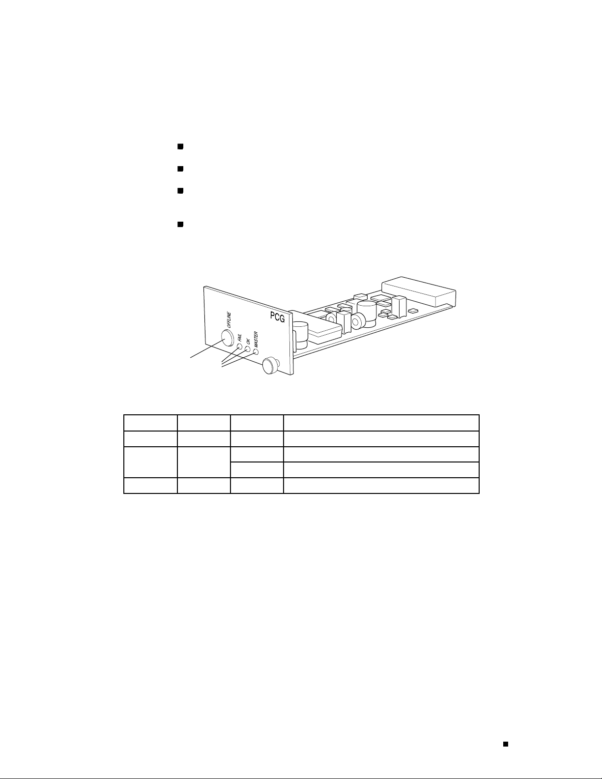
PCG Components
Each PCG (shown in Figure 7) has the following components:
Signal generator—Provides a 125-MHz system clock s ignal.
EEPROM—Stores the serial number and revision level of the PCG.
Three LEDs—Indicate PCG status. There is a blue one labeled MASTER, a green
one labeled
Offline button—Prepares the PCG for removal from the router when pressed.
Figure 7: Packet Forwarding Engine Clock Generator
OK, and an amber one labeled FAIL. Table 6 describes the LED states.
Hardware Component Overview
Offline button
Table 6: States for PCG LEDs
Label Color State Description
MASTER Blue On steadily
FAI L Amber On steadilyPCG has fai
Green
LEDs
On steadily PCG is functioning normally.OK
Blinking
Switching and Forwarding Module (SFM)
The Switching and Forwarding Module (SFM) performs route lookup,
filtering, and switching on incoming data packets, then directs outbound
packets to the appropriate FPC for transmission to the network. It can
process 40 million packets per second (Mpps).
Up to four SFMs can be installed in the router, processing a total of 160 Mpps.
The SFMs are hot-pluggable , as described in Field-Replaceable Units (FRUs) on
page 4. Removing or inserting an SFM causes a brief interruption in forwarding
performance (about 500 ms) as the Packet Forwarding Engine reconfigures
the distribution of packets across the remaining SFMs.
1181
PCG is master.
PCG is starting up.
led.
For SFM replacement instructions, see “Replacing an SFM” on page 188.
Packet Forwarding Engine 19
Page 44

M160 Internet Router Hardware Guide
The SFM communicates with the Routing Engine using a dedicated 100-Mbps Fast
Ethernet link that transfers routing table data from the Routing Engine to the
forwarding table in the Internet Processor II ASIC. The link is a lso used to transfer
from the SFM to the Routing Engine routing link-state updates and other packets
destined for the router that have been received through the router interfaces.
The ASICs and other components on the SFM provide the following functions:
Route lookups—The Internet Processor II ASIC on each SFM performs route
lookups using the forwarding table stored in SSRAM.
Management of shared memory on the FPCs—One Distributed Buffer Manager
ASIC receives the 64-byte data cells into which the I/O Manager ASICs on each
FPC divide incoming packets, and uniformly a llocates them throughout the
shared memory buffers located on the FPCs.
Transfer of outgoing data packets—The second Distributed Buffer Manager
ASIC passes notification of the forwarding decision for each packet to an I/O
Manager ASIC so that data cells for the outgoing packet can be reassembled
for transmission to the network.
Transfer of exception and control packets—The Internet Processor II ASIC
passes exception packets to the microprocessor on the SFM, which processes
almost all of them. The SFM sends any remaining exception packets to
the Routing Engine for further processing. When the SFM detects an error
originating i n t he Packet Forwarding Engine, it sends it to the Routing Engine
using system logging (syslog) messages.
SFM Components
EachSFMisatwo-boardsystem,asshowninFigure8. Ithas
the following components:
Two Distributed Buffer Manager ASICs—Process incoming and outgoing
packets: one distributes data cells (which the I/O Manager ASIC on each
FPC derives from incoming packets) to the shared mem ory buffers on the
20 Packet Forwarding Engine
Page 45
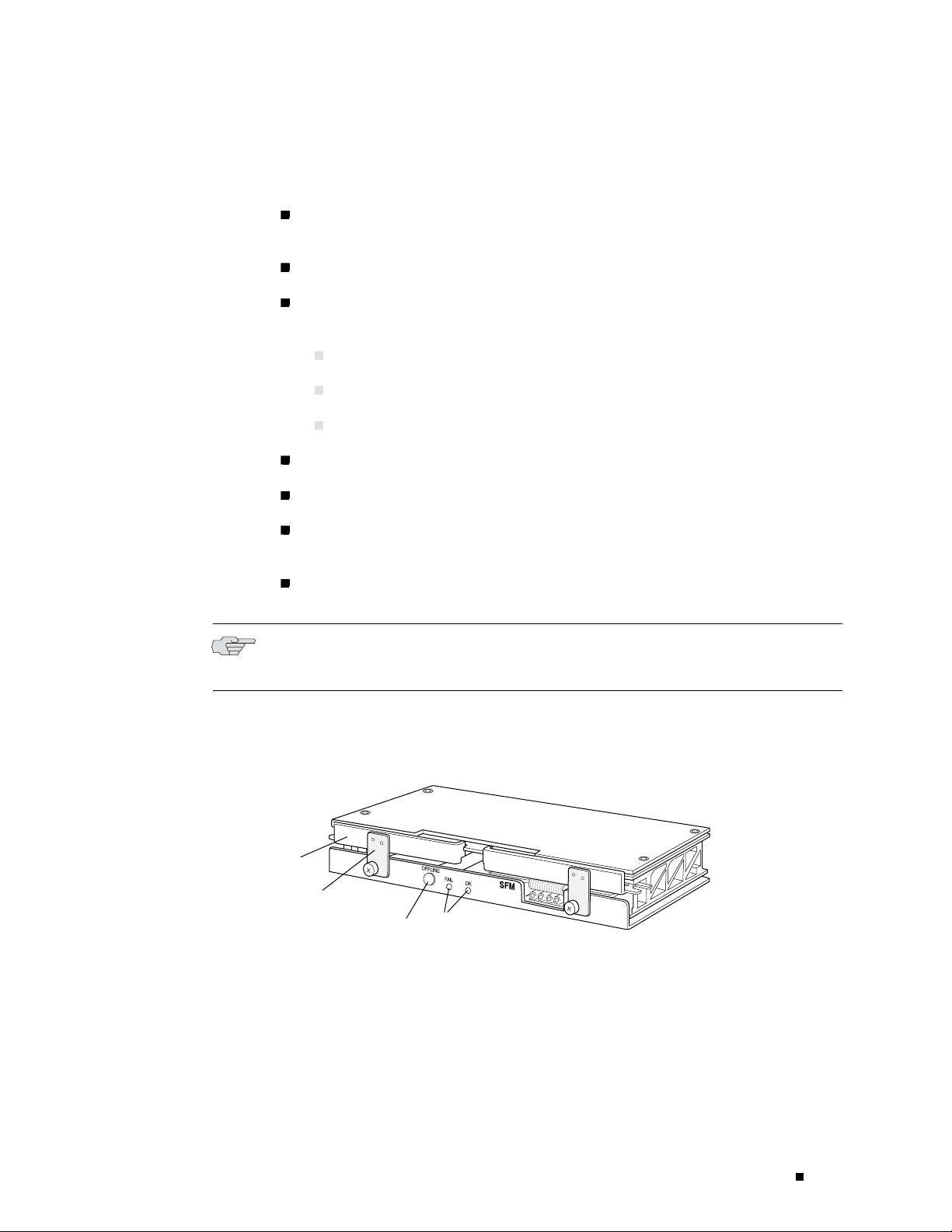
Hardware Component Overview
FPCs, while the second forwards notification of routing decisions to the
I/O Manager ASICs.
One Internet Processor II ASIC—Performs route lookups and makes routing
decisions.
Parity-protected SSRAM—Stores the forwarding table.
Processor subsystem—Manages SFM functions and handles exception packets.
The processor has the following components:
One PowerPC 603e processor
Parity-protected Level 2 cache
Parity-protected DRAM
EEPROM—Stores the serial number and revision level.
Offline button—Prepares the SFM for removal from the router when p ressed.
Two LEDs—Indicate SFM status. There is a green one labeled OK and an amber
one labeled
Ejector handles and locking tabs—Control the locking system that secures the
SFMinthechassis.
NOTE: For specific information about SFM components (for example, the amount of
SSRAM and DRAM), issue the
Figure 8: Switching and Forwarding Module
Ejector handle
Ejector locking tab
Offline button
FAI L . Table 7 describes the LED states.
show chassis sfm detail command.
LEDs
1184
Packet Forwarding Engine 21
Page 46

M160 Internet Router Hardware Guide
Table 7: States for SFM LEDs
Label Color State Description
Green
FAI L Amber On steadily SFM has failed.
Host Module
The host module constructs routing tables, performs system management
functions, and generates the SONET/SDH clock signal for SONET/SDH interfaces. It
consists of a paired Routing Engine and Miscellaneous Control Subsystem (MCS).
For a host module to function, both of its components—Routing Engine and
MCS—must be installed and operational. One or two host modules can be installed
into the midplane from the rear of the chassis, as shown in Figure 3: the Routing
Engine slot labeled
above the
On steadily SFM is functioning normally.OK
Blinking
MCS 1 slot.
SFM is starting up.
RE 0 is below the MCS slot labeled MCS 0 and the RE 1 slot is
If two host modules are installed, both are powered on, but only one is active (the
master); the second host module is in standby mode and performs no functions.
By default, the master host module is the one with components installed in the
RE 0 and MCS 0 slots. To change the default master Routing Engine, include the
appropriate
[edit chassis redundancy routing-engine] statement in the configuration, as
described in the section about Routing Engine redundancy in the JUNOS Internet
Software Configuration Guide: Getting Started.
The host module components are h ot-pluggable, as d escribed in Field-Replaceable
Units (FRUs) on page 4. Removal or failure of one or both components in the
standby host module does not affect router function. If one or both components
in the master host module is removed from the chassis, the effect depends on
whether two host modules are installed:
If there is only one host module, packet forwarding halts until both the Routing
Engine and MCS are reinstalled and functioning normally.
If there are two host modules, the effect depends on the software configuration:
If the Routing Engines are running JUNOS Release 6.0 or later and
are configured for graceful switchover, the standby Routing Engine
automatically assumes mastership without interruption of forwarding
performance. For information about configuring graceful switchover, see
the section about Routing Engine redundancy in JUNOS Internet Software
Configuration Guide: Getting Started.
22 Host Module
Otherwise, forwarding halts while standby host module becomes the
master and the new master Routing Engine resets the Packet Forwarding
Engine.
Page 47

Hardware Component Overview
For host module replacement instructions, see “Replacing an MCS” on page 159
and “Replacing a Routing Engine” on page 165.
Note that the effect of a hardware or software failure on one or both components
in the master host module differs from the effect of removing a component that
belongs to the master host module:
With the default router configuration, in case of failure you must
correct the problem manually. You can issue the appropriate
request chassis routing-engine master commandtoswitchmastershiptotheother
Routing Engine, for example. For information about the command, see the
JUNOS Internet Software Operational Mode Command Reference: Protocols, Class
of Service, Chassis, and Management.
On routers with two installed Routing Engines running JUNOS Rel ease
6.0 or later, you can configure graceful switchover of Routing Engines, as
previously described for the case of Routing Engine removal. When the
standby Routing Engine stops receiving keepalive signals from the master
Routing Engine, it automatically assumes mastership without interruption of
forwarding performance.
Routing Engine
On routers with two installed Routing Engines running any JUNOS release,
you can configure automatic Routing Engine mastership failover. When the
standby Routing Engine stops receiving keepalive signals from the master
Routing Engine, it automatically assumes mastership. Packet forwarding halts
while the Packet Forwarding Engine components reset and connect to the
new master Routing Engine.
For information about configuring graceful switchover or automatic mastership
failover, see the section about Routing Engine redundancy in the JUNOS Internet
Software Configuration Guide: Getting Started.
For more information about host module components, see the following sections:
Routing Engine on page 23
Miscellaneous Control Subsystem (MCS) on page 25
The Routing Engine is an Intel-based PCI platform that runs JUNOS Internet
software. Software processes that run on the Routing Engine maintain the
routing tables, manage the routing protocols used on the router, control the
router’s interfaces, control some chassis components, and provide the interface
for system management and user access to the router.
For a description of the Routing Engine’s role in router architecture ,
see Routing Engine Architecture on page 53.
One or two host modules (paired Routing Engine and MCS) can be installed
into the midplane from the rear of the chassis, as shown in Figure 3. If two
host modules are installed, the Routing Engines together determine which is
Host Module 23
Page 48

M160 Internet Router Hardware Guide
the master and which is in standby mode (and so performs no functions). By
default, the Routing Engine in the slot labeled
Routing Engine also determines which of the two PCGs is the master.
The Routing Engine is hot-pluggable, as described in Field-Replaceable
Units (FRUs) on page 4. For information about the effect of removing a
Routing Engine, see Host Module on page 22. For replacement instructions,
see “Replacing a Routing Engine” on page 165.
Routing Engine Components
TheRoutingEngine(showninFigure9)isatwo-boardsystem
with the following components:
RE0 is the master. The master
CPU—Runs JUNOS Internet software to maintain the router’s routing tables
and routing protocols. It has a Pentium-class processor.
SDRAM—Provides storage for the routing and forwarding tables and for other
Routing Engine processes.
Compact flash drive—Provides primary storage for software images,
configuration files, and microcode. The drive is fixed and inaccessible from
outside the router.
Hard disk—Provides secondary storage for log files, memory dumps, and
rebooting the system if the flash drive fails.
PCcardslots—AcceptremovablePCcards,whichstoresoftwareimages
for system upgrades.
LED—Indicates disk activity for the internal IDE interface. It does not
necessarily indicate routing-related activity.
Interfaces for out-of-band management access—Provide information about
Routing Engine status to devices (console, laptop, or terminal server) that can
be attached to access ports located on the Connector Interface Panel (CIP).
EEPROM—Stores the serial nu mb er of the Routing Engine.
Reset button—Reboots the Routing Engine when pressed.
NOTE: The LEDs that report host module status (and by implication Routing Engine
status) are on the craft interface rather than the Routing Engine faceplate. For more
information, see “Host Module LEDs” on page 31.
24 Host Module
NOTE: The appearance and p osition of electronic components or the PC card
slot on your Routing Engine might differ from Figure 9 and other figures in this
Page 49

document that depict the Routing Engine. These differenc es do not affect Routing
Engine installation and removal or functionality.
For specific information about Routing Engine components (for example, t he
amount of SDRAM), issue the
show chassis routing-engine command.
NOTE: If two Routing Engines are installed, they must both be the same version.
Figure 9: Routing Engine
Routing Engine 333 Routing Engine 600
Extractor clipExtractor clip
Hardware Component Overview
LED
PC card slot
Extractor clip
Miscellaneous Control Subsystem (MCS)
The Miscellaneous Control Subsystem (MCS) works with its companion Routing
Engine to provide control and monitoring functions for router components. It also
generates a clock signal for the S ONET/SDH interfaces on the router.
One or two host modules (paired MCS and Routing Engine) can be installed
into the midplane from the rear of the chassis, as shown in Figure 3. Only
one host module is active at a time, with the optional second host module in
standby mode. For more information about host module interdependence
and redundancy, see Host Module on page 22.
The MCS performs the following functions:
Monitoring and control of router components—The MCS collects statistics
from all sensors in the system. When it detects a failure or alarm condition,
it sends a signal to the Routing Engine, which generates control messages
P
C
C
A
R
J
U
N
D
IP
E
R
N
E
T
W
O
R
K
S
L
A
B
E
L
T
H
IS
S
ID
E
PC card slot
RESET
HD
LED
Extractor clip
1596
Host Module 25
Page 50

M160 Internet Router Hardware Guide
or sets an alarm. The MCS also relays control messages from the Routing
Engine to the router components.
Controlling component power-up and power-down—The MCS controls the
power-up sequence of router components as they start, and powers down
components when their offline buttons are pressed.
Signaling of mastership—In a router with more than one host module, the
MCS signals to all router components which host module is the master and
which is the standby. It relays the mastership signal for the two PCGs as well.
Providing SONET/SDH clock source—The MCS generates a 19.44-MHz
SONET/SDH clock signal, along with a signal that indicates which MCS is the
master SONET/SDH clock generator (if two MCSs are installed).
Clock monitoring—The MCS monitors the PCG system clock and its
SONET/SDH clock to verify that they are providing the expected signal. It
generates an alarm if a clock signal is incorrect.
Control of FPC resets—If the MCS detects errors in an FPC, it attempts to
reset the FPC. After three unsuccessful reset attempts, the MCS takes the
FPC offline and informs the Routing Engine. Other FPCs are unaffected,
and system operation continues.
MCS Components
Each MCS (shown in Figure 10) has the following components:
PCI interface—Connects the MCS to the Routing Engine.
100-Mbps Ethernet switch—Carries signals and monitoring data between
router components.
19.44-MHz stratum 3 reference clock—Generates clock signal for SONET/SDH
PICs.
I2C controller—Monitors the status of router components.
Three LEDs—Indicate MCS status. Th ere is a blue one labeled MASTER, a green
one labeled
Offline button—Prepares the MCS for removal from the router when pressed.
Extractor clips—Control the locking system that secures the MCS in the chassis.
OK, and an amber one labeled FAIL. Table 8 describes the LED states.
26 Host Module
Page 51

Figure 10: Miscellaneous Control Subsystem
Extractor clip
Hardware Component Overview
Offline button
Table 8: States for MCS LEDs
Label Color State Description
MASTER Blue On steadily
Green
FAI L Amber On steadilyMCS has fai
Craft Interface
Thecraftinterfaceprovidesstatusandtroubleshootinginformationataglanceand
has buttons for deactivating alarms and preparing FPCs for removal. The craft
interface is located on the front of the chassis above the FPC card cage, as shown in
Figure 1. It includes the elements shown in Figure 11.
LEDs
On steadily MCS is functioning normally.OK
Blinking
1178
Extractor clip
MCS is master.
MCS is starting up.
led.
Craft Interface 27
Page 52

M160 Internet Router Hardware Guide
Figure 11: Craft Interface
Yellow alarm
LED
FAIL
OK
FPC 0 FPC 1
Red alarm
LED
FAIL
FPC 5
Host module
LEDs
OFFLINE ONLINE
OFFLINE ONLINE
FAIL
OK
FPC 6
OK
MASTER
MASTER
HOST0
HOST1
FAIL
FPC 7
Alarm cutoff
button
OK
ACO/LT
FAIL
FPC 2
buttons
OK
MENU
ENTER
FAIL
FPC 3
LCDNavigation
Navigation
buttons
FAIL
OK
FPC 4
OK
FAIL
FPC LEDs and offline buttons (for FPC 0-7)
NOTE: The LEDs for some router components are located on the component
faceplate, rather than on the craft interface. For information about those LEDs, see
the following sections:
“PCG Components” on page 19
“SFM Components” on page 20
“MCS Components” on page 26
OK
1231
Power System on page 35
For information about the elements on the craft interface, see the following sections:
Alarm LEDs and Alarm Cutoff/Lamp Test Button on page 28
LCD and Navigation Buttons on page 29
Host Module LEDs on page 3 1
FPC LEDs and Offline Button on page 31
Alarm LEDs and Alarm Cutoff/Lamp Test Button
Two large alarm LEDs are located at the upper left of the craft interface
(see Figure 11). The circular red LED lights t o indicate a critical condition
that can result in a system shutdown. The triangular yellow LED lights to
indicate a less severe condition that requires monitoring or maintenance.
Both LEDs can be lit simultaneously.
A condition that causes an LED to light also activates the corresponding alarm
relay contact on the connector interface panel (CIP), as described in “Alarm
28 Craft Interface
Page 53

Hardware Component Overview
Relay Contacts” on page 34. The LCD on t he craft interface reports the cause
of the alarm, as described in “LCD Alarm Mode” on page 30.
To deactivate red and yellow alarms, press the button labeled
cutoff/lamp test”), which is located to the left of the alarm LEDs. Deactivating an
alarm turns off both LEDs and deactivates the device attached to the corresponding
alarm relay contact on the CIP. However, the LCD continues to report the alarm
message until you clear the condition that caused the alarm.
Table 9 describes the alarm LEDs and alarm cutoff button in more detail.
Table 9: Alarm LEDs and Alarm Cutoff/Lamp Test Button
Shape Color State Description
Red On steadily Critical alarm LED—Indicates a critical condition
that can cause the router to stop functioning.
Possible causes include component removal,
failure, or overheating.
Yellow On steadily Warning alarm LED—Indicates a serious but
nonfatal error condition, such as a maintenance
alert or a significant increase in component
temperature.
——
Alarm cutoff/lamp test button—Deactivates red
and yellow alarms. Causes all LEDs on the craft
interface to light (f or testing purposes), when
pressed and held.
ACO/LT (for “alarm
LCD and Navigation Buttons
A four-line LCD is located in the craft interface, along with six navigation buttons.
The LCD operates in two modes, as described in the following sections:
LCDIdleModeonpage29
LCD Alarm Mode on page 30
LCD Idle Mode
During normal operation, the LCD operates in idle mode and reports
current status information, as shown in Figure 12.
Craft Interface 29
Page 54

M160 Internet Router Hardware Guide
Figure 12: LCD in Idle Mode
MENU
Router1
Up 2 + 11:59
ENTER
Power OK
The lines in the display report the following information:
First line—Routing node name.
Second line—Length of time the router has been running, reported in the
following form:
Up days + hours : minutes
Third and fourth lines—Status messages, which rotate at two-second intervals.
Some conditions, such as removal or insertion of a system component,
can interrupt the messages.
To add a message that alternates every 2 seconds with the default status
messages, use the
set chassis display message command. For more information,
see the JUNOS Internet Software Operational Mode Command Reference:
Protocols, Class of Service, Chassis, and Management.
1263
LCD Alarm Mode
When a red or yellow alarm occurs, the LCD switches to alarm mode and
reports about the alarm condition, as shown in Figure 13.
Figure 13: LCD in Alarm Mode
MENU
ENTER
Router1
2
R: PEM 1 Input Failure
Y: Change air filter
1264
30 Craft Interface
Page 55

Host Module LEDs
Hardware Component Overview
The lines in the display report the following information:
First line—Routing node name.
Second line—Number of active alarms.
Third and fourth lines—Individual alarm messages, with the most severe
condition shown first. The prefix on each line indicates whether the alarm is a
red (
R) or yellow (Y) alarm.
For a list of alarm messages that can appear on the LCD, see “Chassis
and Interface Alarm Messages” on page 209.
Attheupperrightcornerofthecraftinterface(seeFigure11)aretwosetsofLEDs
that indicate host module status: the set labeled
Routing Engine in slot
thestatusoftheRoutingEngineinslot
RE 0 and MCS in slot MCS 0, and the set labeled HOST1 reports
RE 1 and the MCS in slot MCS 1.Eachset
includes three LEDs—a green one labeled
ONLINE, and a red one labeled OFFLINE. T able 10 describes the LED states.
HOST0 reports the status of the
MASTER, another green one labeled
Table 10: States for Host Module LEDs
Label Color State Description
Green
Green
FPC LEDs a
MASTER
ONLINE
OFFLINE Red On steadily One or both host module components are not
nd Offline Button
The LEDS and offline button for each FPC are l ocated directly above it on the
craft interface, as shown in Figure 11. The red LED labeled
LED labeled
The offline button, lab eled with the FPC slot number (for example,
prepares the FPC for removal from the router when pressed.
On steadily Host module is functioning as master.
On steadily Host module components (Routing Engine and
MCS) are installed and functioning normally.
Blinking Host module is starting up.
installed or have failed.
FAI L and the green
OK indicate FPC status, as described in Table 11.
FPC2),
Craft Interface 31
Page 56

M160 Internet Router Hardware Guide
Table 11: States for FPC LEDs
Label Color State Description
OK
FAI L Red On steadily FPC has failed.
Green
On steadily FPC is functioning normally.
Blinking FPC is starting up or going offline.
Off FPC is offline or not installed.
Connector Interface Panel (CIP)
The Connect
or Interface Panel (CIP) is located at the left side of the FPC card cage,
as shown in Figure 1 . It houses Routing Engine management ports and alarm relay
contacts, as shown in Figure 14 and described in the following sections:
Routing Engine Management Ports on page 33
BITS Input
Ports on page 34
Alarm R elay Contacts on page 34
32 Connector Interface Panel (CIP)
Page 57

Figure 14: Connector Interface Panel
HOST
0
ETHERNET
ACT
YEL=10Mb
GRN=100Mb
CONSOLE
Hardware Component Overview
AUXILIARY
HOST
ETHERNET
ACT
YEL=10Mb
GRN=100Mb
CONSOLE
AUXILIARY
RED ALARM
NC
C
NO
NC
C
NO
YELLOW
ALARM
1
BITS A
LINK
BITS B
Engine ports
BITS
input ports
Routing
LINK
Alarm relay
contacts
Routing Engine Management Ports
On the upper half of the CIP are two sets of ports for connecting the Routing
Engines to one or more external devices on which system administrators can issue
JUNOS command-line interface (CLI) commands to manage the router. The s et of
ports labeled
set labeled
HOST0 connects to the Routing Engine in the slot labeled RE 0,andthe
HOST1 connects to the Routing Engine in the slot labeled RE 1.
1204
Connector Interface Panel (CIP) 33
Page 58

M160 Internet Router Hardware Guide
The ports with the indicated label in each set function as follow s :
For information about the pinouts for the connectors, see “Cable
Connector Pinouts” on page 269.
ETHERNET—Connects the Routing Engine through an Ethernet connection to a
management LAN (or any other device that plugs into an Ethernet connection)
for out-of-band management. The port uses an autosensing RJ-45 connector to
support both 10 - and 100-Mbps connections. Two small LEDs on the left edge
of the port indicate the connection in use: the LED labeled
ETHERNET lights
yellow or green for a 10-Mbps or 100-Mbps connection, and the LED lab eled
ACT lights green when traffic is passing through the port.
CONSOLE—Connects the Routing Engine to a system console through an
RS-232 (EIA-232) serial cable.
AUXILIARY— Connects the Routing Engine to a laptop, modem, or other
auxiliary device through an RS-232 (EIA-232) serial cable.
Figure 15 shows the ports that connect to the Routing Engine installed in slot
The arrangement of ports for the Routing Engine installed in slot RE 1 is the same.
Figure 15: Routing Engine Interface Ports for Host Module 0
HOST
0
ETHERNET
ACT
Ethernet
LEDs
YEL=10Mb
GRN=100Mb
Ethernet port
Console port
CONSOLE
Auxiliary port
AUXILIARY
BITS Input Por ts
RE 0.
1236
In the center of the CIP are two ports labeled BITS A and BITS B (see Figure 16). The
router does not support BITS input, so these ports do not function.
Alarm Relay Contacts
At the bottom of the CIP are two relay contacts for connecting the router to
external alarm-reporting devices, the upper labeled
34 Connector Interface Panel (CIP)
RED ALARM and the lower
Page 59

YELLOW ALARM (see Fi gure 16). A system condition that causes the red or yellow
alarm LED to light on the craft interface also activates the corresponding alarm
relay contact. For instructions for attaching a device to the alarm relay contacts,
see “Connecting to an External Alarm-Reporting Device” on page 115.
Figure 16: Alarm Relay Contacts and BITS Input Ports
BITS A
LINK
BITS B
LINK
RED ALARM
NC
C
NO
NC
C
NO
YELLOW
ALARM
Hardware Component Overview
BITS
input ports
Alarm relay
contacts
Power System
1173
The router uses DC power. There are two load-sharing, pass-through power supplies
located at the bottom rear of the chassis, as shown in Figure 2. The power supplies
connect to the midplane, which distributes power to router components according
to their individual voltage requirements. When the pow er supplies are installed
and operational, they automatically share the electrical load. If a power supply
stops functioning for any reason, the remaining power supplies instantly begin
providing all the power the router needs for normal functioning and can provide
full power indefinitely.
Pow er supplies are hot-removable and hot-insertable, as described in
Field-Replaceable Units (FRUs) on page 4. To avoid electrical injury, carefully follow
the instructions in “Replacing a Power Supply” on page 197.
NOTE: After powering off a power supply, wait at least 60 seconds before turning
it back on. After powering on a power supply, wait at least 60 seconds before
turning it off.
If the r outer is completely powered down when you power on the power supply,
the Routing Engine boots as the power supply completes its startup sequence. If
Power System 35
Page 60

M160 Internet Router Hardware Guide
the Routing Engine finishes booting and you need to power down the router
again, first issue the CLI
“Disconnecting Power from the Router” on page 200.
After a p ower supply is powered on, it can take up to 60 seconds for status
indicators—such a s LEDs on the power supply,
messages on the craft interface LCD—to indicate that the power supply is
functioning normally. Ignore error indicators that appear during the first 60 seconds.
See the following sections for further information:
request system halt command. For more information, see
show chassis commands, and
Power Supply on page 36
Circuit Breaker Box on page 38
Fuses on page 39
Power Supply
The router has two load-sharing, pass-through power supplies, located at the
bottom rear of the chassis, as shown in Figure 2. For information about power
supply redundancy and replaceability, see Power System on page 35.
Each power supply has the following components (see Figure 17 and Figure 18):
LEDs—Indicate power supply status. There is a green one labeled CB ON,a
blue one labeled
power supply also has an amber LED labeled
OUTPUT OK, and an amber one labeled CB OFF.Theoriginal
NO AIRFLOW. Table 12 describes
the LED states.
In addition, power supply failure triggers the red alarm LED on the craft
interface and the
RED ALARM relay c ontact on the CIP. See “Alarm LEDs and
Alarm Cutoff/Lamp Test Button” on page 28.
Self-test button—Tests the power supply. Do not press this button; it is for use
by qualified service personnel only .
36 Power System
Page 61

Figure 17: Original Power Supply
Figure 18: Enhanced Power Supply
Hardware Component Overview
C
B
O
N
O
U
T
P
U
T
O
K
N
O
A
I
R
F
L
O
W
C
B
O
F
F
P
E
M
S
E
L
F
T
E
S
T
1219
ENHANCED PEM
CAUTION
TURN OFF CIRCUIT
BREAKER BEFORE REMOVING
OR INSERTING PEM.
INSERT PEM THEN
TURN ON CIRCUIT
BREAKER AFTER 1 MINUTE.
TIGHTEN THESE SCREWS FIRST
CB ON
OUTPUT OK
PEM
SELF TEST
CB OFF
Table 12: States for Power Supply LEDs
Label Color State Description
CB ON
Green
OUTPUT OK Blue
1266
On steadily Power supply is inserted correctly and is receiving
power. Circuit breaker is on.
On steadily Power supply is inserted and is functioning
normally.
Blinking Power supply is not functioning, is starting up, or is
not properly inserted, or airflow is not sufficient.
Power System 37
Page 62

M160 Internet Router Hardware Guide
Label Color State Description
NO
AIRFLOW
(original
power
supply only)
CB OFF Amber On steadily Power supply is functioning, but the circuit breaker
Amber On steadily Power supply is inserted, but airflow around the
Table 13 lists electrical specifications for the power supply.
Table 13: Electrical Specifications for Power Supply
power supply is not sufficient.
is off.
Descriptio
Maximum power output
DC input voltage Nominal: –48 VDC, –60 VDC
DC input current rating 80 A @ –48 V
Output voltages +48 V @ 8.3 A (cooling system), +8.3 V @ 6 A (bias), –48 V to
Circuit Breaker Box
n
Specificat
Original power supply: 2400 W; nonisolated
Enhanced power supply: 3000 W; nonisolated
Operating range: –42 to –72 VDC
–60 V@ 75 A
ion
The circuit breaker box is located on the rear of the chassis, above the
right power supply, as shown in Figure 2.
The circuit breaker box houses two circuit breakers and sets of terminal studs,
corresponding positionally to the two power supplies, as shown in Figure 19.
For proper router operation and power load sharing, connect a different
external DC power source to each set of terminal studs.
In addition, a grounding cable attaches to separate grounding points located
above the circuit breaker box, as shown in Figure 2. For more information, see
“Power, Connection, and Cable Specifications” on page 67.
38 Power System
Page 63

Figure 19: Circuit Breaker Box
Hardware Component Overview
1225
Fuses
Cooling System
The router uses fuses from the Cooper Bussman brand GMT series for the FPCs,
MCSs, PCGs, and SFMs. The fuses are located in a fuse box on the rear of the
midplane. When the fuse for a component blows, the component stops functioning
even though it is installed correctly and the power supplies are providing power to
the router. For more information, see “Blown Fuse Indicators” on page 211. For
fuse replacement instructions, see “Replacing a Fuse” on p age 204.
The cooling system includes a f a n tray and several impellers that draw room air into
the chassis to ke ep its internal temperature below a maximum acceptable level.
When the temperature is below the maximum, the fans and impellers function
at less than full speed. If the MCS detects that the temperature of a component
has exceeded the acceptable maximum—for example, because an impeller is
removed—it automatically increases the speed of the remaining impellers and fans
to reduce the temperature. The fans and impellers can function at the higher
speed indefinitely.
For more information about the cooling system, see the following sections:
Cooling System Components on page 40
Airflow through the Chassis on page 40
Cooling System 39
Page 64

M160 Internet Router Hardware Guide
Cooling System Components
The cooling system has the following components. All are hot-removable and
hot-insertable, as described in Field-Replaceable Units (FRUs) on page 4.
Air intake vent, air filter, and intake cover—Provide an opening for room air to
enter the router. They are located at the bottom of the chassis front, below the
cable management system, as shown in Figure 1. The air filter is removable
and covers the air intake vent, preventing dust and other particles from
entering the cooling system. For maintenance and replacement instructions,
see “Maintaining the Air Filter” on page 128. The nonremovable air intake
cover is located behind the air filter and provides EMC shielding.
CAUTION: Do not remove the air filter for more than a few minutes while the
router is operating. The fans and impellers are powerful enough to draw in foreign
material, such as bits of wire, through the unfiltered air intake, which could damage
router components.
Front cooling subsystem—Cools the FPCs, PICs, and midplane. It includes a fan
tray located behind the cable management system and a large, central impeller
behind the craft interface. For replacement instructions, see “Replacing the Fan
Tray” on page 148 and “Replacing the Front Impeller Assembly” on page 150.
Rear cooling subsystem—Cools the SFMs, host module, PCGs, and power
supplies. It includes one impeller located at the upper right of the chassis
rear and another at the lower left, as shown in Figure 2. The upper and
lower impellers are not interchangeable. For replacement instructions, see
“Replacing the Rear Lower Impeller Assembly” on page 154 and “Replacing
the Rear Upper Impeller Assembly” on page 156.
Airflow through the Chassis
Figure 20 shows airflow through the chassis and the location of
the impellers and fan tray.
40 Cooling System
Page 65

Figure 20: Airflow through the Chassis
Hardware Component Overview
Front view
Impeller
Card cage
Air intake cover
Cable Management System
The cable management system (see Figure 21) consists of a row of nine
semicircular plastic bobbins mounted on t he front of the router below the FPC
card cage. The PIC cables pass between the bobbins and into the tray , keeping
the cables organized and securely in place. The curvature of the bobbins also
helps maintain the proper bend radius for optical PIC cables.
Front
Side view
Impeller
Fan tray
Rear
Top view
Rear
Impeller
(upper rear)
Impeller
(upper front)
1170
Front
Figure 21: Cable Management System
Cable management
system
1938
Cable Management System 41
Page 66

M160 Internet Router Hardware Guide
42 Cable Managem ent System
Page 67

Chapter 3
JUNOS Internet Software Overview
The JUNOS Internet software is especially designed for the large production
networks t ypically supported by Internet Service Providers (ISPs). It incorporates
Internet Protocol (IP) routing software and software for management of interfaces,
networks, and the router chassis.
TheJUNOSInternetsoftwarerunsontheRoutingEngine.Thesoftwareconsistsof
processes that support Internet routing protocols, control the router’s interfaces
and the router chassis itself, and provide an interface for system management.
The processes run on top of a kernel that coordinates the communication among
processes and has a direct link to the Packet Forwarding Engine software.
Use the JUNOS Internet software to configure the routing protocols that run on
the router and the properties of router interfaces. After you have activated a
software configuration, use the JUNOS Internet software to monitor the protocol
traffic passing through the router and to troubleshoot protocol and network
connectivity problems.
For additional information about the JUNOS Internet software, including its security
features and a list of the industry standards it supports, see the JUNOS System Basics
Configuration Guide. For complete information about configuring the software,
including examples, see the JUNOS Internet software configuration guides.
This chapter discusses the following topics:
Routing Engine Software Components on page 43
Tools for Accessing and Configuring t he Software on page 50
Tools for Monitoring the Software on page 50
Software Upgrades on page 50
Routing Engine Software Components
The Routing Engine software consists of several software pro cesses that control
router functions and a kernel that coordinates communication among the
processes, as described in the following sections:
Routing Protocol Process on page 44
Routing Engine Software Components 43
Page 68

M160 Internet Router Hardware Guide
Routing Protocol Process
The JUNOS software routing protocol process controls the routing p rotocols that
run on the router. The routing protocol process starts all configured routing
protocols and handles all routing messages. It consolidates the routing information
learned from all routing protocols into common routing tables. From this routing
information, the routing protocol process determines the active routes to network
destinations and installs these routes into the Routing Engine’s forwarding table.
Finally, the routing protocol process implements the routing policies you specify,
which determine how routing information is transferred between the routing
protocols and the routing table.
VPNs on page 48
Interface Process on page 49
Chassis Process on page 49
SNMP and MIB II Processes on page 49
Management Process on page 4 9
Routing Engine Kernel on page 49
This section discusses the following topics:
IPv4 Routing Protocols on page 44
IPv6 Routing Protocols on page 46
Routing and Forwarding Tables on page 47
Routing Policy on page 47
For complete information about routing concepts, see the JUNOS
Internet software configuration guides.
IPv4 Routing Protocols
The JUNOS Internet software implements full IP routing functionality,
providing support for IP version 4 (IPv4). The routing protocols are fully
interoperable with existing IP routing protocols and provide the scale and
control necessary for the Internet core. The software provides support for
the following routing and traffic engineering protocols:
Unicast routing protocols
BGP—Border Gateway Protocol, version 4, is an Exterior Gateway Protocol
(EGP) that guarantees loop-free exchange of routing information between
routing domains (also called autonomous systems). BGP, in conjunction
44 Routing Engine Software Components
Page 69

JUNOS Internet Software Overview
with JUNOS routing policy, provides a system of administrative checks and
balances that can be used to implement peering and transit agreements.
ICMP—Internet Control Message Protocol router discovery is a method
that hosts can use to discover the addresses of operational routers on a
subnet.
IS-IS—Intermediate System-to-Intermediate System is a link-state interior
gateway protocol (IGP) for IP networks that uses the shortest-path-first
algorithm (SPF algorithm, also called the Dijkstra algorithm) to determine
routes.
OSPF—Open Shortest Path First, version 2, is an IGP developed for
IP networks by the Int ernet Engineering Task Force (IETF). OSPF is
a link-state protocol that makes routing decisions based on the SPF
algorithm.
RIP—Routing Information Protocol, version 2, is an IGP for IP networks
based on the Bellman-Ford algorithm. RIP is a distance-vector protocol.
RIP dynamically routes packets between a subscriber and a service
provider without the subscriber having to configure BGP or to participate
in the service provider’s IGP discovery process.
Multicast routing protocols
DVMRP—Distance Vector Multicast Routing Protocol is a dense-mode
(flood-and-prune) multicast routing protocol.
IGMP—Internet Group Management Protocol, versions 1 and 2, is used
to manage membership in multicast groups.
MSDP—Multicast Source Discovery Protocol enables multiple PIM sparse
mode domains to be joined. A rendezvous point (RP) in a PIM sparse
mode domain has a peering relationship with an RP in another domain,
thereby discovering multicast sources from other domains.
PIM sparse mode and dense mode—Protocol-Independent Multicast is a
multicast routing protocol used to route traffic to multicast groups that
might span wide-area and interdomain internetworks. In PIM sparse
mode, routers explicitly join and leave multicast groups. PIM dense
mode is a flood-and-prune protocol.
SAP/SDP—Session Announcement Protocol and Session Description
Protocol handle conference session announcements.
MPLS application protocols
LDP—Label Distribution Protocol provides a mechanism for distributing
labels in nontraffic-engineered applications. LDP allows routers to
establish label-switched paths (LSPs) through a network by mapping
network-layer routing information directly to data-link layer switched
Routing Engine Software Components 45
Page 70

M160 Internet Router Hardware Guide
IPv6 Routing Protocols
The JUNOS Internet software implements full IP routing functionality,
providing support for IP version 6 (IPv6). The routing protocols are fully
interoperable with existing IP routing protocols and provide the scale and
control necessary for the Internet core. The software provides support
for the following unicast routing protocols:
paths. LSPs created by LDP can also traverse LSPs created by Resource
Reservation Protocol (RSVP).
MPLS—Multiprotocol Label Switching enables you to configure LSPs
through a network either manually or dynamically. You can control how
traffic traverses the network by directing it through particular paths,
rather than relying on an IGP’s least-cost algorithm to choose a path.
RSVP—Resource Reservation Protocol, version 1, provides a mechanism
for engineering network traffic patterns that is independent of the
shortest path determined by a routing protocol. RSVP itself is not a
routing protocol, but is designed to operate with current and future
unicast and multicast routing protocols. JUNOS RSVP software supports
dynamic signaling for MPLS LSPs.
BGP—Border Gateway Protocol, version 4, is an EGP that guarantees loop-free
exchange of routing information between routing domains (also called
autonomous systems). BGP, in conjunction with JUNOS routing policy, provides
a system of administrative checks and balances that can be used to implement
peering and transit agreements.
ICMP—Internet Control Message Protocol router discovery is a method that
hosts can use to discover the addresses of operational routers on a subnet.
IS-IS—Intermediate System-to-Intermediate System is a link-state interior
gateway protocol (IGP) for IP networks that uses the shortest-path-first
algorithm (SPF algorithm, also called the Dijkstra algorithm) to determine
routes.
OSPF—Open Shortest Path First, ver sion 3 (OSPFv3), supports version 6 of
the Internet Protocol (IPv6). The fundamental mechanisms of OSPF such as
flooding, Designated Router (DR) election, area based topologies and the
Shortest Path First (SPF) calculations remain unchanged. Some differences
exist either due to changes in protocol semantics between IPv4 and IPv6, or to
handle the increased address size of IPv6.
RIP—Routing Information Protocol, version 2, is an IGP for IP networks
based on the Bellman-Ford algorithm. RIP is a distance-vector protocol. RIP
dynamically routes packets between a subscriber and a service provider
without the subscriber having to configure BGP or to participate in the service
provider’s IGP discovery process.
46 Routing Engine Software Components
Page 71

JUNOS Internet Software Overview
Routing and Forwarding Tables
The primary function of the JUNOS routing protocol process is maintaining routing
tables and using the information in them to determine active routes to network
destinations. It copies information about the active routes into the Routing Engine’s
forwarding table, which the JUNOS kernel copies to the Packet Forwarding Engine.
By default, the routing protocol process maintains the following routing tables and
uses the information in each table to determine activeroutes to network destinations:
Unicast routing table—Stores routing information for all unicast protocols
running on the router, including BGP, IS-IS, OSPF, and RIP. You can also
configure additional routes, such as static routes, for inclusion in the routing
table. The unicast routing protocols use the routes in this table when
advertising routing information to their neighbors.
In the unicast routing table, the routing protocol process designates routes with
the lowest preference values as active. By default, a route’s preference value is
simply a function of how the routing protocol process learned about the route.
You can modify the default preference value by setting routing policies and
configuring other software parameters. See “Routing Policy” on page 47.
Multicast routing table (cache)—Stores routing information for all multicast
protocols running on the router, including DVMRP and PIM. You can configure
additional routes for inclusion in the routing table.
In the multicast routing table, the routing protocol process uses traffic flow and
other parameters specified by the multicast routing protocol algorithms to
select active routes.
MPLS routing table—Stores MPLS label information.
For unicast routes, the routing protocol process determines active routes by
choosing the most preferred route, which is the route with the lowest preference
value. By default, the route’s preference value is simply a function of how the
routing protocol process learned about the route. You can modify the default
preference value using routing policy and with software configuration parameters.
For multicast traffic, the routing protocol process determines active routes based
on traffic flow and other parameters specified by the multicast routing protocol
algorithms. The routing protocol process then installs one or more active routes to
each network destination into the Routing Engine’s forwarding table.
You can configure additional routing tables to meet your requirements, as
described in the JUNOS Routing Protocols Configuration Guide.
Routing Policy
By default, all routing protocols place their rout es into the routing table.
When advertising routes, the routing protocols, by default, advertise only
a limited set of routes from the routing table. Specifically, each routing
protocol exports only the active routes that were learned by that protocol.
Routing Engine Software Components 47
Page 72

M160 Internet Router Hardware Guide
In addition, IGPs (IS-IS, OSPF, and RIP) export the direct (interface) routes
for the interfaces on which the protocol is explicitly configured.
For each routing table, you can affect the routes that a protocol places into the table
and the routes from the table that the protocol advertises by defining one or more
routing policies and then applying them to the specific routing protocol.
Routing policies applied when t he routing protocol places routes into the routing
table are called import policies because the routes are being imported into
the routing table. Policies applied when the routing protocol is advertising
routes that are in the routing table are called export policies because the
routes are being exported from the routing table. In other words, the terms
import and export are used with respect to the routing table.
Routing policy enables you to control (filter) which routes are imported into the
routing table and which routes are exported from the routing table. Routing policy
also allows you to set the information associated with a route as it is being imported
into or exported from the routing table. Routing policies applied to imported routes
control the routes used to determine active routes, whereas policies applied to
exported routes control which routes a protocol advertises to its neighbors.
VPNs
You implement routing policy by defining policies. A policy specifies the conditions
tousetomatcharouteandtheactiontoperformontheroutewhenamatch
occurs. For example, when a routing table imports routing information from a
routing protocol, a routing policy might modify the route’s preference, mark the
route with a color to identify it for later manipulation, or prevent the route from
even being installed in a routing table. When a routing table exports routes to a
routing protocol, a policy might assign metric values, modify t he BGP community
information, tag the route with additional information, or prevent the route
from being exported altogether. You also can define policies for redistributing
the routes learned from one protocol into another protocol.
The JUNOS software supports several types of VPNs:
Layer 2 VPNs—A Layer 2 VPN links a set of sites sharing common routing
information, and whose connectivity is controlled by a collection of policies. A
Layer 2 VPN is not aware of routes within a customer’s network. It simply
provides private links between a customer’s sites over the service provider’s
existing public Internet backbone.
Layer3VPNs—ALayer3VPNlinksasetofsitesthatsharecommonrouting
information, and whose connectivity is controlled by a collection of policies.
A Layer 3 VPN is aware of routes within a customer’s network, requiring
more configuration on the part of the service provider than a Layer 2 VPN.
The sites that make up a Layer 3 VPN are connected over a service provider’s
existing public Internet backbone.
Interprovider VPNs—An interprovider VPN supplies connectivity between two
VPNs in separate autonomous systems (ASs). This functionality could be used
48 Routing Engine Software Components
Page 73

Interface Process
JUNOS Internet Software Overview
by a VPN customer with connections to several various ISPs, or different
connections to the same ISP in various geographic regions.
Carrier-of-Carrier VPNs—Carrier-of-carrier VPNs allow a VPN service provider
to supply VPN service to a customer who is also a service provider. The latter
service provider s upplies Internet or VPN service to an end customer.
The JUNOS interface process manages the physical interface devices and logical
interfaces on the router. It implements the JUNOS command-line interface
(CLI) commands and configuration statements that you use to specify interface
properties such as location (FPC location in the FPC card cage and PIC location
on an FPC), the interface type (such as SONET/SDH or ATM), encapsulation,
and interface-specific properties. You can configure both interfaces that are
currently active and interfaces that might be installed later.
The JUNOS interface process communicates with the interface process in the
Packet Forwarding Engine through the JUNOS kernel, enabling the JUNOS Internet
software to track the status and condition of router interfaces.
Chassis Process
The JUNOS chassis process allows you to configure and control the properties of
the router, including conditions that trigger alarms and clock sources. The chassis
process communicates directly with a chassis process in the JUNOS kernel.
SNMP and MIB II Processes
The JUNOS Internet software supports the Simple Network Management
Protocol (SNMP), versions 1, 2, and 3, which provides a mechanism for
monitoring the state of the router. This software is controlled by the JUNOS
SNMP and Management Information Base (MIB) II processes, which consist
of an SNMP master agent and a MIB II agent.
Management Process
The management process starts all the other JUNOS software processes and the
CLI when the router boots. It monitors the running JUNOS processes and makes
all reasonable attempts to restart any process that terminates.
Routing Engine Kernel
The Routing Engine kernel provides the underlying infrastructure for all JUNOS
software processes. It also pro vides the link between the routing tables maintained
by the routing protocol process and the forwarding table maintained by the Routing
Engine. Additionally, it coordinates communication with the Packet Forwarding
Engine, which primarily involves synchronizing the Packet Forwarding Engine’s
forwarding table with the master forwarding table maintained by the Routing Engine.
Routing Engine Software Components 49
Page 74

M160 Internet Router Hardware Guide
Tools for Accessing and Configuring the Software
The JUNOS CLI is the primary tool for accessing and controlling the JUNOS Internet
software. You use it when accessing the router through the console or a connection
to an out-of-band management network. The CLI includes command s for
configuring router hardware, the JUNOS Internet software, and network connectivity.
The JUNOS CLI is a straightforward command interface. You type commands
on a single line and enter the commands by pressing the Enter key. The CLI
provides command help and command completion, as well as Emacs-style
keyboard sequences for moving around on a command line and scrolling through
a buffer that contains recently executed commands. For more information
about the CLI, see the JUNOS System Basics Configuration Guide.
Tools for Monitoring the Software
In addition to commands for configuring router hardw are and software, the CLI
includes commands for monitoring and troubleshooting hardware, software, routing
protocols, and network connectivity. CLI commands display information from
routing tables, information specific to routing protocols, a nd information about
network connectivity derived from the
ping and traceroute utilities.
Software Upgrades
You can also use the JUNOS Internet software i mplementation of SNMP to monitor
routers. The SNMP software consists of an SNMP master agent and a MIB II agent.
It provides full support for MIB II SNMP version 1 traps and version 2 notifications,
SNMP version 1
information about SNMP, see the JUNOS Network Management Configuration Guide.
The software also supports tracing and logging operations, which you can use
to track normal router operations, error conditions, and the packets that the
router generates or forwards. Logging operations use a syslog-like mechanism to
record systemwide, high-level events such as interfaces going up or down and
user logins on the router. Tracing operations record more detailed information
about the operation of routing protocols, such as the various types of routing
protocol packets sent and received, and routing policy actions.
The router is delivered with the JUNOS Internet software preinstalled. To upgrade
the software, you use CLI commands to copy a set of software images over the
network to memory storage on the Routing Engine. The JUNOS Internet software
setconsistsofseveralimagesprovidedinindividualpackagesorasabundle. You
normally upgrade all packages simultaneously. For information about installing and
upgrading JUNOS software, see the JUNOS System Basics Configuration Guide.
Get and GetNext requests, and version 2 GetBulk requests. For more
50 Software Upgrades
Page 75

Chapter 4
System Architecture Overview
The router architecture consists of two major components:
Packet Forwarding Engine—Performs Layer 2 and Layer 3 packet switching,
route lookups, and packet forwarding.
Routing Engine—Provides Layer 3 routing services and network management.
The Packet Forwarding Engine and the Routing Engine perform independently but
communicate constantly through a 100-Mbps internal link. This arrangement
provides streamlined forwarding and r outing control and the ability to run
Internet-scale networks at high speeds. Figure 22 illustrates the relationship
between the Packet Forwarding Engine and the Routing Engine.
Figure 22: System Architecture
Routing Engine
100-Mbps link
Packets
in
For a discussion of the architectural components, see the following sections:
Packet Forwarding Engine Architecture on page 51
RoutingEngineArchitectureonpage53
Packet Forwarding
Engine
Packet Forwarding Engine Architecture
The Packet Forwarding Engine performs Layer 2 and Layer 3 packet switching.
It can forward up to 160 for all packet sizes. The aggregate throughput for the
router is 160 gigabits per second (Gbps) simplex or 80 Gbps full duplex. The
Packet Forwar ding Engine is implemented in application-specific integrated circuits
(ASICs). It uses a centralized route lookup engine and shared memory.
Packets
out
Packet Forwarding Engine Architecture 51
1244
Page 76

M160 Internet Router Hardware Guide
The Packet Forwarding Engine architecture includes the following components:
Midplane—Transports packets, notifications, and other signals between the
FPCs and the Packet Forwarding Engine (as well as other system components).
Physical Interface Card (PIC)—Physically connects the router to fiber-optic
or digital network media. A controller ASIC in each PIC performs control
functions specific to the PIC media type.
Flexible PIC Concentrator (FPC)—Houses PICs and provides shared memory
for processing incoming and outgoing packets. Each FPC hosts four I/O
Manager ASICs, which divide incoming data packets into memory blocks (cells)
before passing them to the SFMs, and reassembles cells into data packets when
the packets are ready for transmission. The FPC also hosts two Packet Director
ASICs—one distributes incoming packets among the I/O Manager ASICs, and
the other distributes outgoing packets to the appropriate PICs on the FPC.
Switching and Forwarding Module (SFM)—Hosts an Internet Processor II ASIC,
which makes forwarding decisions, and two Distributed Buffer Manager ASICs:
one distributes data cells to the shared memory buffers on the FPCs and the
other notifies the FPCs of forwarding decisions for outgoing packets.
Data Flow through the Packet Forwarding Engine
Use of ASICs promotes efficient movement of data packets through
the system. Packets flow through the Packet Forwarding Engine in
the following sequence (see Figure 23):
1. Packets a rrive at an incoming PIC interface.
2. The PIC passes the packets to the FPC, where the Packet Director ASIC
distributes them among the I/O Manager ASICs.
3. The I/O Manager ASICs process the packet headers, divide the packets into
64-byte data cells, and pass the cells through the midplane to the SFMs.
4. The Distributed Buffer Manager ASICs on the SFMs distribute the data cells
throughout memory buffers located on and shared by all the FPCs.
5. For each packet, an Internet Processor II ASIC on an SFM performs a route
lookup and decides how to forward the packet.
6. The Internet Processor II ASIC notifies a Distributed Buffer Manager ASIC of
the forwarding decision, and the Distributed Buffer Manager ASIC forwards the
notification to the FPC that hosts the appropriate outbound interface.
7. The I/O Manager ASIC on the FPC reassembles data cells in shared memory
into data packets as they are ready for transmission and passes them through
the Packet Director ASIC to the outbound PIC.
8. The outbound PIC transmits the data packets.
52 Packet Forwarding Engine Architecture
Page 77

Figure 23: Packet Forwarding Engine Components and Data Flow
Midplane
System Architecture Overview
Packet
in
Controller
Packet
out
PIC
Routing Engine Architecture
The Routing Engine is an Intel-based PCI platform running the JUNOS Internet
software, which Juniper Networks has developed and optimized to handle
large numbers of network interfaces and routes. The software consists of
a set of system processes running in protected memory modules on top
of an independent operating sy stem. The JUNOS kernel supports JUNOS
system processes, which handle system management processes, routing
protocols, and control functions (see Figure 24).
FPC
I/O
Manager
Packet
Director
Distributed
Buffer
Manager
Processor II
Routing
Engine
SFM
Internet
= ASIC
1234
The Routing Engine has a dedicated 1 00-Mbps internal connection
to the Packet Forwarding Engine.
Routing Engine Architecture 53
Page 78

M160 Internet Router Hardware Guide
Figure 24: Routing Engine Architecture
JUNOS
software
management
Routing Engine Functions
The Routing Engine handles all routing protocol processes, as well as
the software processes that control the router’s interfaces, the chassis
components, system management, and user access to the router. These
routing and software processes run on top of a kernel that interacts with the
Packet Forwarding Engine. For more information about the processes, see
Routing Engine Software Components on page 43.
The Routing Engine includes the following functions and features:
System
processes
Routing
protocols
Kernel
Intel-based PCI platform
Control
functions
System processes
Operating system
1164
Processing of routing protocol packets—The Routing Engine handles all
packets that concern routing protocols, freeing the Packet Forwarding Engine
to handle only packets that represent Internet traffic.
Software modularity—Because each software process is devoted to a different
function and uses a separate process space, the failure of one process has little
or no effect on the others.
In-depth Internet functionality—Each routing protocol is implemented with a
complete set of Internet features and provides full flexibility for advertising,
filtering, and modifying routes. Routing policies are set according to route
parameters (for example, prefix, prefix lengths, and Border Gateway Protocol
[BGP] attributes).
Scalability—The JUNOS routing tables have been designed to hold all the
routes in current networks with ample capacity for expansion. Additionally, the
54 Routing Engine Architecture
Page 79

System Architecture Overview
JUNOS Internet software can efficiently support large numbers of interfaces
and virtual circuits.
Management interface—Differe nt levels of system management tools are
provided, including the JUNOS command-line interface (CLI), the JUNOScript
application programming interface, the craft interface, and SNMP.
Storage and change management—Configuration files, system images, and
microcode can be held and maintained in primary and secondary storage
systems, permitting local or remote upgrades.
Monitoring efficiency and flexibility—The router supports functions such
as alarm handling and packet counting on every port, without degrading
packet-forwarding performance.
The Routing Engine constructs and maintains one or more routing tables (see
Figure 25). From the routing tables, the Routing Engine derives a table of active
routes, called the forwarding table, which is then copied into the Packet Forwarding
Engine. The design of the ASICs allow the forwarding table in the Packet Forwarding
Engine to be updated without interrupting forwarding performance.
Figure 25: Control Packet Handling for Routing and Forwarding Table Updates
Routing protocol
process
Forwarding table
updates
Packets
in
Routing Engine
Forwarding table
Packet Forwarding
Engines
Routing protocol
packets from network
Packets
out
1240
Routing Engine Architecture 55
Page 80

M160 Internet Router Hardware Guide
56 Routing Engine Architecture
Page 81

Part 2
Initial Installation
Preparing for Router Installation on page 59
Unpacking the Router on page 77
Installing the Router Using a Mechanical Lift on page 81
Installing the Router without a Mechanical Lift on page 83
Connecting the Router and Performing Initial Configuration on page 111
Initial Installat ion 57
Page 82

58 Initial Installatio n
Page 83

Chapter 5
Preparing for Router Installation
This chapter describes how to prepare your site for installation of the M160 Internet
router. It discusse s the following topics:
Rack Requirements on page 59
Clearance Requirements for Airflow and Hardware Maintenance on page 62
Routing Node Environmental Specifications on page 62
Fire Safety Requirements on page 63
Power Guidelines, Requirements, and Specifications on page 64
Network Cable Specifications and Guidelines on page 70
Routing Engine Interface Cable and Wire Specifications on page 74
Site Preparation Checklist on page 75
Rack Requirements
The router must be installed in a rack. Many types of racks are acceptable, including
front-mount racks, 4-post (telco) racks, and center-mount racks. An example of a
center-mount rack appears in Figure 26.
The following sections describe rack requirements:
Rack Size and Strength on page 60
Spacing of Mounting Holes on page 61
Connection to Building Structure on page 62
Rack Requirements 59
Page 84

M160 Internet Router Hardware Guide
Rack Size and Strength
The router is designed for installation in a rack that complies with
either of the following standards:
A 19-in. rack as defined in Cabinets,Racks,Panels,andAssociatedEquipment
(document number EIA-310-D) published by the Electronics Industry
Association (
http://www.eia.org).
A 600-mm rack as defined in the four-part Equipment Engineering (EE);
European telecommunications standard for equipment practice (document
numbers ETS 300 119-1 through 119-4) published by the European
Telecommunications Standards Institute (
http://www.etsi.org).
The horizontal spacing between the rails in a rack that complies with
this standard is usually wider than the router’s front support posts and
center-mounting brackets, which measure 19 in. (48.3 cm) from outer edge
toouteredge. Useapprovedwingdevicestonarrowtheopeningbetween
the rails as required.
The rack rails must be spaced widely enough to accommodate the router chassis’s
external dimensions: 35 in. (89 cm) high, 29 in. (73.6 cm) deep, and 17.5 in.
(44.5 cm) wide. The outer edges of the front support posts and center-mounting
brackets extend the width to 19 in. (48. 3 cm). The spacing of rails and adjacent
racks must also allow for the clearances around the router and rack that are specified
in Clearance Requirements for Airflow and Hardware Maintenance on page 62.
NOTE: The router might not fit into an 800-mm-deep cabinet, even if you adjust the
front-to-back position of the front mounting rails inside the cabinet.
If you mount the router in a cabinet, be sure that ventilation is sufficient to
prevent overheating.
In general, a center-mount rack is preferable to a front-mount rack because
the more even distribution of weight in the center-mount rack provides
greater stability. If a front-mount rack is used, we recommend supporting
the back of the router with a shelf or other structure.
The chassis height of 35 in. (89 cm) is approximately 20 U. A
U is the
standard rack unit defined in Cabinets, Racks, Panels, and Associated Equipment
(document number EIA-310-D) published by the Electronics Industry
Association. You can stack eight M160 routers in a rack that has at least
40 U (70 in. or 1.78 m) of usable vertical space.
60 Rack Requirements
The rack must be strong enough to support the weight of the fully configured
router, up to about 370.5 lb (168 kg). If you stack eight routers in one rack,
it must be capable of supporting about 740 lb (336 kg).
Page 85

Figure 26: Typical Center-Mount Rack
(2.13 m)
Preparing for Router Installation
19 in. (48.3 cm)
Mounting rails
7 ft
Floor bolts
1011
Spacing of Mounting Holes
Table 14 specifies the spacing between mounting holes in the chassis’s front support
posts and center-mounting brackets. The mounting holes in a front-mount rack’s
rails must align with the holes in the front support posts, and the mounting holes in a
center-mount rack’s rails must align with the holes in the center-mounting brackets.
Table 14: Spacing of Holes on Front Support Post and Center-Mounting Bracket
Router Mounting Rail Hole Spacing
Front support post 4 U (7 in. or 17.78 cm)
Center-mounting bracket
3U(5.25in. or13.33cm)
Rack Requirements 61
Page 86

M160 Internet Router Hardware Guide
Connection to Building Structure
Always secure the rack to the structure of the building. If your geographical
area is subject to earthquakes, bolt the rack to the floor. For maximum
stability, also secure the rack to ceiling brackets. For more information, see
“Rack-Mounting Requirements and Warnings” on page 240.
Clearance Requirements for Airflow and Hardware Maintenance
When planning the installation site, you need to allow sufficient
clearance around the rack (see Figure 27):
For the cooling system to function properly, the airflow around the chassis
must be unrestricted. Figure 20 depicts the airflow in the router.
For service personnel to remove and install hardware components, there must
be adequate space at the front and back of the router. Allow at least 24 in.
(61cm)bothinfrontoftherouterandbehindit.
Figure 27: Chassis Dimensions and Clearance Requirements
Top down view
24 in. (61 cm) clearance
for maintenance
Front of chassis
19 in.
(48.3 cm)
Center rack-mount ears
29 in.
(73.6 cm)
19 in.
(48.3 cm)
Routing Node Environmental Specifications
24 in. (61 cm) clearance
for maintenance
6 in. (15.2 cm) clearance
for airflow
17.5 in.
(44.5 cm)
6 in. (15.2 cm) clearance
Rear of chassis
for airflow
1169
Table 15 specifies the environmental specifications required for normal
router operation. In addition, the site should be as dust-free as possible.
Dust can clog air intake vents, reducing cooling system efficiency. Check the
vents frequently, cleaning them as necessary. For more information, see
“Maintaining Hardware Components” on page 127.
62 Routing Node Environmental Specifications
Page 87

Table 15: Routing Node Environmental Specifications
Description Value
Altitude No performance degradation to 10,000 ft (3048 m)
Relative humidity Normal operation ensured in relative humidity range of 5% to
90%, noncondensing
Temperatu r e
Seismic
Maximum thermal output 9400 BTU/hour
Normal operation ensured in temperature range of 32°F (0°C) to
104°F (40°C)
Non-operating storage temperature in shipping crate:
–40°F (–40°C) to 158°F (70°C)
Tested to meet Telcordia Technologies Zone 4 earthquake
requirements
Preparing for Router Installation
NOTE: Install the router only in restricted areas, such as dedicated equipment
rooms and equipment closets, in accordance with Articles 110-16, 110-17, and
110-18 of the National Electrical Code, ANSI/NFPA 70.
For additional safety guidelines and requirements, see “Safety and Regulatory
Compliance Information” on page 221.
Fire Safety Requirements
In the event of a fire emergency involving routers and other network equipment,
the safety of people is the primary concern. You should establish procedures for
protecting people in the event of a fire emergency, provide safety training, and
properly provision fire-control equipment and fire extinguishers.
In addition, you should establish procedures to protect your equipment in the
event of a fire emergency. Juniper Networks products should be installed in
an environment suitable for electronic equipment. We recommend that fire
suppression equipment be available in the event of a fire in the vicinity of the
equipment, and that all local fire, safety, and electrical codes and ordinances
be observed when installing and operating your equipment.
Fire Suppression
In the event of an electrical hazard or an electrical fire, you should first turn power
off to the equipment at the source. Then use a Type C fire extinguisher, which uses
noncorrosive fire retardants, to extinguish the fire. For more information about
fire extinguishers, see “Fire Suppression Equipment” on page 64.
Fire Safety Requirements 63
Page 88

M160 Internet Router Hardware Guide
Fire Suppression Equipment
Type C fire extinguishers, w hich use noncorrosive fire retardants such as carbon
dioxide (CO2) and Halotron™, are most effective for suppressing electrical fires.
Type C fir e extinguishers displace the oxygen from the point of combustion to
eliminate the fire. For extinguishing fire on or around equipment that draws air from
the environment for cooling, you should use this type of inert oxygen displacement
extinguisher instead of an extinguisher that leave residues on equipment.
Do not use multipurpose Type ABC chemical fire extinguishers (dry chemical
fire extinguishers) near Juniper Networks equipment. The primary ingredient in
these fire extinguishers is monoammonium phosphate, which is very sticky and
difficult to clean. In addition, in minute amounts of mois ture, monoammonium
phosphate can become highly corrosive and corrodes most metals.
Any equipment in a room in which a chemical fire extinguisher has been
discharged is subject to premature failure and unreliable operation. The
equipment is considered to be irreparably damaged.
NOTE: To keep warranties effective, do not use a dry chemical fire extinguisher to
control a fire at or near a Juniper Networks router. If a dry chemical fire extinguisher
is used, the unit is no longer eligible for coverage under a service agreement.
We recommend that you dispose of any irreparably damaged equipment
in an environmentally responsible manner.
Power Guidelines, Requirements, and Specifications
The router uses DC power. There are two load-sharing, pass-through power supplies
located at the bottom rear of the chassis, as shown in Figure 2. The power supplies
connect to the midplane, which distributes power to router components according
to their individual voltage requirements. When the pow er supplies are installed
and operational, they automatically share the electrical load. If a power supply
stops functioning for any reason, the remaining power supplies instantly begin
providing all the power the router needs for normal functioning and can provide
full power indefinitely.
For site wiring and power system guidelines, requirements, and specifications, see
the following sections:
Site Electrical Wiring Guidelines on page 65
Router Power Requirements on page 65
Chassis Grounding on page 67
Power, Connection, and Cable Specifications on page 67
64 Power Guidelines, Requirements, and Specifications
Page 89

Site Electrical Wiring Guidelines
When planning the electrical wiring at your site, consider the factors
discussed in the following sections.
Distance Limitations for Signaling
Improperly installed wires can emit radio interference. In addition, the potential
for damage from lightning strikes increases if wires exceed recommended
distances, or if wires p ass between buildings. The electromagnetic pulse (EMP)
caused by lightning can damage unshielded conductors and destroy electronic
devices. If y our site has previously experienced such problems, you might want
to consult experts in electrical surge suppression and shielding.
Radio Frequency Interference
You can reduce or eliminate the emission of radio frequency interference (RFI) from
your site wiring by using twisted-pair cable with a good distribution of grounding
conductors. If you must exceed the recommended distances, use a high-quality
twisted-pair cable with one ground conductor for each data signal when applicable.
Preparing for Router Installation
Electromagnetic Compatibility
If your site is susceptible to problems with electromagnetic compatibility
(EMC), particularly from lightning or radio transmitters, you might want to
seek expert advice. Strong sources of electromagnetic interference (EMI) can
destroy the signal drivers and receivers in the router and conduct power
surges over the lines into the equipment, resulting in an electrical hazard.
It is particularly important to provide a properly grounded and shielded
environment and to use electrical surge-suppression devices.
CAUTION: To comply with intrabuilding lightning/surge requirements, int rabuilding
wiring must be shielded, and the shield for the wiring must be grounded at both
ends.
Router Power Requirements
Table 16 lists the power requirements for various hardware components
when the router is operating under typical voltage conditions. For PIC power
requirements, see the M160 Internet Router PIC Guide.
Power Guidelines, Requirements, and Specifications 65
Page 90

M160 Internet Router Hardware Guide
Table 16: Component Power Requirements
Component Power Requirement (Amps)
Base system (cooling system, power supplies, and craft
interface)
Hostmodule(RoutingEngineandMCS) 1.3A/48V
FPC
PCG
SFM
7-10 A/48 V
2.4A/48V
0.2A/48V
1.3A/48V
You can use the information in Table 16 and the M160 Internet Router PIC
Guide to calculate power consumption for various hardware configurations,
input current from a different source voltage, and thermal output, as shown
in the following examples. (For an added safety margin, the examples use
a generalized value for PICs of 0.625 A/48 V each.)
Power consumption for minimum configuration:
Base system + 1 FPC + 1 SFM + 1 host module + 2 PCGs + 4 PICs =
7 A + 2.4 A + 1.3 A + 1.3 A + 2(0.2 A) + 4(0.625 A) =
7 A + 2.4 A + 1.3 A + 1.3 A + 0.4 A + 2.5 A = 14.9 A @ 48 V = 715 W DC
Pow er consumption for maximum configuration:
Base system + 8 FPCs + 4 SFMs + 2 host modules + 2 PCGs + 32 PICs =
10 A + 8(2.4 A) + 4(1.3 A) + 2(1.3 A) + 2(0.2 A) + 32(0.625 A) =
10A + 19.2A + 5.2A + 2.6A + 0.4A + 20A=57.4A@48V=2755WDC
Input current from a DC source other than 48 V (based on maximum
configuration):
(54 VDC input) x (input current X) = (48 VDC input) x (input current Y)
54 x X = 48 x 57.4 A
X=48 x 57.4A/54=51.0A
System thermal output for maximally configured router:
105% of Watts DC/0.293 = BTU/hr
1.05 x 2755/0.293 = 9873 BTU/hr
NOTE: If you plan to operate a maximally configured router, we recommend that
you provision at least 70 A @ 48 VDC and use a facility circuit breaker rated for
70 A minimum. Doing so enables you to operate the router in any configuration
without upgrading the po wer infrastructure, and allows the router to function at
full capacity using one power supply.
If you plan to operate the router at less than the maximum configuration and do not
provision a 70 A circuit breaker, we recommend that you provision a circuit breaker
rated for at least 125% of the continuous current that the system dra ws at 48 V.
66 Power Guidelines, Requirements, and Specifications
Page 91
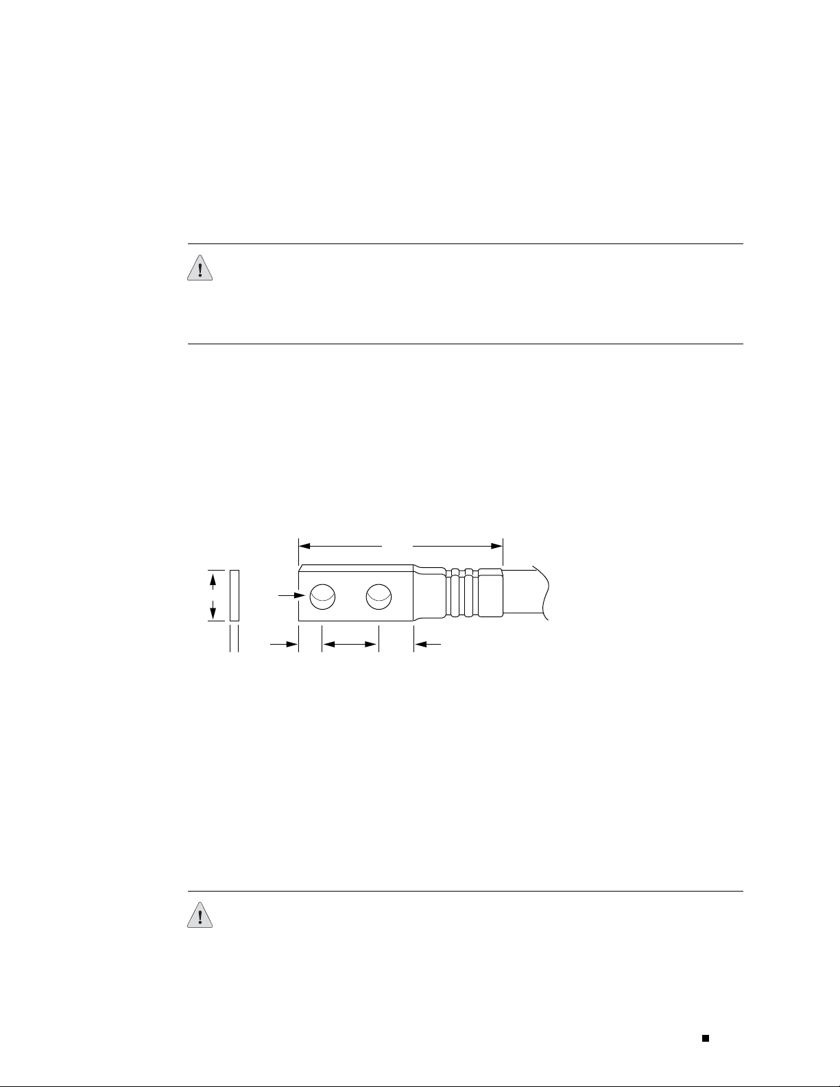
Chassis Grounding
Preparing for Router Installation
To meet safety and electromagnetic interference (EMI) requirements and to
ensure proper operation, the router must be adequately grounded before power
is connected. A pair of threaded inserts (PEM nuts) are provided on the right
rear of the chassis for connecting the router to earth ground.
CAUTION: Before router installation begins, a licensed electrician must attach a
cable lug to the grounding and power cables that you supply. A cable with an
incorrectly attached lug can damage the router (for example, by causing a short
circuit).
To ground the router, connect a grounding cable to earth ground and then
attach it to the chassis grounding points. The grounding points are spaced at
0.625-in. (15.86-mm) centers. The accessory box shipped with the router
includes the cable lug that attaches to the grounding cable (see Figure 28) and
the UNC 1/4–20 screws (American) used to secure the grounding cable to the
grounding points. (The cable lug shown in Figure 28 is also used for the DC power
cables.) Thegroundingcablemustbeabletohandleupto82A.
Figure 28: Power and Grounding Cable Lug
End view
0.55
0.08
0.28
2 holes
0.63
0.25 0.37
2.25
Thegroundingcablemustbe8-AWG(8.4m2) wire, minimum, or
as permitted by the local code.
Power, Connection, and Cable Specifications
To supply power to the router, connect power cables to a separate, dedicated power
source for each p ower supply and attach the cables to the terminal studs on the
circuit breaker box. Most sites distribute power through a main conduit that leads
to frame-mounted power distribution panels, one of which might be located at the
top of the rack that houses the router. A pair of cables (one input and one return)
connects each set of terminal studs to the power distribution panel.
Crimp area
All measurements in inches
g002137
CAUTION: There is no standard color coding for DC power cables. The color coding
used by the external DC power source at your site determines the color coding
for the leads on the power cables that attach to the terminal studs on the circuit
Power Guidelines, Requirements, and Specifications 67
Page 92
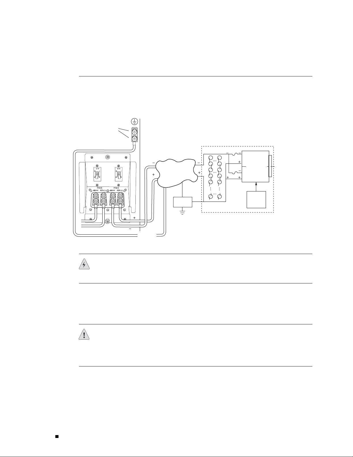
M160 Internet Router Hardware Guide
breaker box. You must ensure that power connections maintain the proper polarity.
The power source cables might be labeled
Figure 29 shows a typical source cabling arrangement.
Figure 29: Typical Source Cabling to the Router
Chassis
grounding
points
(+) and (–) to indicate their polarity.
AC
1975
Central
office ground
Central office
primary & secondary
DC power distribution
Ground
window
Central
office ground
Batteries
Rectifiers
Plant
controls
Battery plant
WARNING: Power plant ground and chassis ground must be connected to the
same building ground.
Table 17 summarizes the specifications for the grounding and power cables, which
you supply. The accessory box shipped with the router includes the cable lugs that
attach to the terminal studs of the circuit breaker box (see Figure 28). (The cable
lug shown in Figure 28 is also used for the grounding the chassis.)
CAUTION: Before router installation begins, a licensed electrician must attach a
cable lug to the grounding and power cables that you supply. A cable with an
incorrectly attached lug can damage the router (for example, by causing a short
circuit).
68 Power Guidelines, Requirements, and Specifications
Page 93

Table 17: DC Power and Grounding Cable Specifications
Cable Type Quantity and S
Power
Grounding One 8-AWG (8.4 mm2) wire, minimum, or as permitted
Eight 4-AWG (16 mm2) wires, minimum, or as permitted
by the local code
by the local code
WARNING: For field-wiring connections, use copper conductors only.
For other electrical safety information, see “Electrical Safety Guidelines and
Warnings” on page 227.
pecification
Preparing for Router Installation
Maximum
Equal Length
None
None
CAUTION: Power cords and cables must not block access to router components or
drape where people could trip on them.
Figure 30 shows how to attach the power cables. The power cables attach
to the 1/4–20 UNC terminal studs located on the circuit breaker box—
the input set of studs is labeled
–48V andthereturnsetislabeledRTN(+).
Thenutsandlockingwashersusedtosecurethepowercablelugson
the terminal studs are preinstalled on the studs.
The tool for loosening or tightening the nuts on the terminal studs is a
7/16-in. hexagonal-head external drive socket wrench, or nut driver, with
a minimum of 30 lb-in. (3.5 Nm) tightening torque.
CAUTION: Do not substitute a metric nut driver or wrench. A tool that does not fit
thenutsexactlycandamagethem.Ifa7/16-in.toolisnotavailable,usepliersor
an ad justable wrench.
Power Guidelines, Requirements, and Specifications 69
Page 94
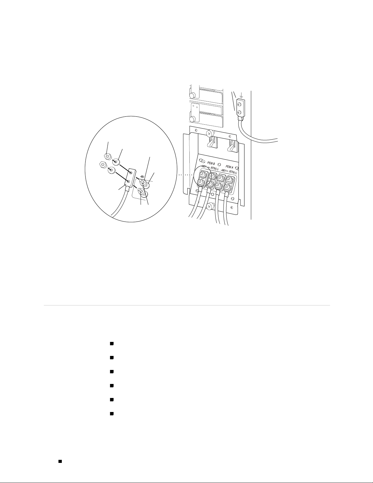
M160 Internet Router Hardware Guide
Figure 30: Power and Grounding Cable Connections
Grounding
points
Nut
Flat washer
Nut
Flat washer
Cable lug
Terminal studs
For information about the DC power supply, including electrical specifications and
a description of components, see “Power Supply” on page 36. For instructions
on connecting the DC power and grounding cables during initial installation, see
“Connecting Power to the Router” on page 117. For instructions on replacing a
DC power cable, see “Disconnecting and Connecting Power” on page 200.
Network Cable Specifications and Guidelines
To ground
g001226
The various PICs supported on the router accept different kinds of network cable,
including multimode and single-mode fiber-optic cable. For more information, see
the following sections:
Fiber Optic and Network Cable Specifications on page 71
Signal Loss in Multimode and Single-Mode Fiber-Optic Cable on page 71
Attenuation and Dispersion in Fiber-Optic Cable on page 71
Calculating Power Budget for Fiber-Optic Cable on page 72
Calculating Power Margin for Fiber-Optic Cable on page 73
Attenuating to Prevent Saturation at SONET/SDH PICs on page 74
70 Network Cable Specifications and Guidelines
Page 95

Fiber Optic and Network Cable Specifications
The router supports PICs that use various kinds of network cable, including
multimode and single-mode fiber-optic cable. For information about the type
ofcableusedbyeachPIC,seetheM160 Internet Router PIC Guide.
Signal Loss in Multimode and Single-Mode Fiber-Optic Cable
Multimode fiber is large enough in diameter to allow rays of light to reflect internally
(bounce off the walls of the fiber). Interfaces with multimode optics typically
use LEDs as light sources. LEDs are not coherent sources, however. They spray
varying wavelengths of light into the multimode fiber, which reflects the light at
different angles. Light rays travel in jagged lines through a multimode fiber, causing
signal dispersion. When light trav eling in the fiber core radiates into the fiber
cladding, higher-order mode loss (HOL) results. Together these factors limit the
transmission distance of multimode fiber compared to single-mode fiber.
Single-mode fiber is so small in diameter that rays of light can reflect internally
through one layer only. Interfaces with single-mode optics use lasers as
light sources. Lasers generate a single wavelength of light, which travels in
astraightlinethroughthesingle-modefiber. Comparedwithmultimode
fiber, single-mode fiber has higher bandwidth and can carry signals for
longer distances. It is consequently more expensive.
Preparing for Router Installation
For information about the maximum transmission distance and supported
wavelength range for the types of single-mode and multimode fiber-optic cable
used by PICs on the M160 router, see the M 160 Internet Router PIC Guide.
Exceeding the maximum transmission distances can result in significant
signal loss, which causes unreliable transmission.
The router uses optical lasers for SONET/SDH PIC single-mode interfaces.
TheseopticscomplywithIR-1ofBellcoreGR-253-COREIssue2,
December 1995 and ANSI TI.105.06.
Attenuation and Dispersion in Fiber-Optic Cable
Correct functioning of an optical data link depends on modulated light reaching
the receiver with enough power to be demodulated correctly. Attenuation is the
reduction in power of the light signal as it is transmitted. Attenuation is caused
by passive media components, such as cables, cable splices, and connectors.
While attenuation is significantly lower for optical fiber than for other media, it
still occurs in both multimode and single-mode transmission. An efficient optical
data link must have enough light available to overcome attenuation.
Network Cable Specifications and Guidelines 71
Page 96

M160 Internet Router Hardware Guide
Dispersion is the spreading of the signal in time. The following two types
of dispersion can affect an optical data link:
For multimode transmission, modal dispersion, rather than chromatic
dispersion or attenuation, usually limits the maximum bit rate and link length.
For single-mode transmission, modal dispersion is not a factor. However ,
at higher bit rates and over longer distances, chromatic dispersion rather
than modal dispersion limits maximum link length.
An efficient optical data link must have enough light to exceed the minimum
power that the receiver requires to operate within its specifications. In addition,
the total dispersion must be less than the limits specified for the type of link in
Telcordia Technologies document GR-253-CORE (Section 4.3) and International
Telecommunications Union (ITU) document G.957.
Chromatic dispersion— The spreading of the signal in time resulting from
the different speeds of light rays.
Modal dispersion—The spreading of the signal in time resulting from the
different propagation modes in the fiber.
When chromatic dispersion is at the maximum allowed, its effect can be considered
as a power penalty in the power budget. The op tical power budget must allow
for the sum of component attenuation, power penalties (including those from
dispersion), and a safety margin for unexpected losses. For more information about
power budget, see “Calculating Power Budget for Fiber-Optic Cable” on page 72.
Calculating Power Budget for Fiber-Optic Cable
To ensure that fiber-optic connections have sufficient power for correct operation,
you need to calculate the link’s power budget, which is the maximum amount
of power it can transmit. When you calculate the power budget, you use a
worst-case analysis to provide a margin of error, even though all the parts of
an actual system do not operate at the worst-case levels. To calculate the
worst-case estimate of power budget (
power (
PB=PT–P
The following hypothetical power budget equation uses values measured in
decibels (dB) and decibels referred to one milliwatt (dBm):
PB=PT–P
PB=–15dBm–(–28dBm)
P
) and minimum receiver sensitivity (PR):
T
R
R
P
), you assume minimum transmitter
B
PB=13dB
72 Network Cable Specifications and Guidelines
Page 97

Calculating Power Margin for Fiber-Optic Cable
After calculating a link’s power budget (using the equation described in
“Calculating Power Budget for Fiber-Optic Cable” on page 72), you can
calculate the pow er margin (
available after subtracting attenuation or link loss (
(
P
).Aworst-caseestimateofPMassumes maximum LL:
B
PM=PB–LL
A PMgreater than zero indicates that the power budget is sufficient
to operate the receiver.
Factors that can cause link loss include higher-order mode losses, modal and
chromatic dispersion, connectors, splices, and fiber attenuation. Table 18
lists an estimated amount of loss for the factors used in the following sample
calculations. For information about the actual amount of signal loss caused
by equipment and other factors, refer to vendor documentation.
P
M
Preparing for Router Installation
),whichrepresentstheamountofpower
LL) from the power budget
Table 18: Estimated Values for Factors Causing Link Loss
Link-Loss Factor Estimated Link-Loss Value
Higher-order mode losses Single-mode—None
Modal and chromatic dispersion Single-mode—None
Connector
Splice 0.5 dB
Fiber attenuation Single-mode—0.5 dB/km
The following example uses the estimated values in Table 18 to calculate link loss
(
LL)fora2km-longmultimodelinkwithapowerbudget(P
Fiber attenuation for 2 km @ 1.0 dB/km= 2 dB
Loss for five connectors @ 0.5 dB per connector = 5(0.5 dB) = 2.5 dB
Loss for two splices @ 0.5 dB per splice =2(0.5 dB) = 1 dB
Multimode—0.5 dB
Multimode—None, if product of bandwidth and distance
is less than 500 MHz–km
0.5 dB
Multimode—1 dB/km
)of13dB:
B
Higher-order loss = 0.5 dB
Clock recovery module = 1 dB
P
The power margin (
) is calculated as follows:
M
Network Cable Specifications and Guidelines 73
Page 98

M160 Internet Router Hardware Guide
PM=PB–LL
PM=13dB–2km(1.0dB/km)–5(0.5dB)–2(0.5dB)–0.5dB[HOL]–1dB[CRM]
PM=13dB–2dB–2.5dB–1dB–0.5dB–1dB
PM=6dB
The following sample calculation for an 8 km-long single-mode link with
a power budget (
calculate link loss (
or 4 dB) and loss for seven connectors (0.5 dB per connector, or 3.5 dB).
The power margin (
PM=PB–LL
PM=13dB–8km(0.5dB/km)–7(0.5dB)
PM=13dB–4dB–3.5dB
P
) of 13 dB uses the estimated values from Table 18 to
B
LL) as the sum of fiber attenuation (8 km @ 0.5 dB/km,
P
) is calculated as follows:
M
PM=5.5dB
In both examples, the calculated power margin is great er than zero,
indicating that the link has sufficient power for transmission and does
not exceed the maximum receiver input power.
Attenuating to Prevent Satu ration at SONET/SDH PICs
SONET/SDH interfaces in the different reach classes—short reach (SR), intermediate
reach (IR), and long reach (LR)—generate different output power levels and
tolerate different input power levels. Interfaces that have a longer reach can
transmit enough power to saturate the receivers on PICs that have a shorter reach.
Specifically, LR interfaces can saturate IR PICs, and both IR and LR interfaces can
saturate SR PICs. Interfaces in the same reach class can also saturate one another.
To prevent saturation, you might need to attenuate pow er at the PIC receiver,
particularly if you know that it has a shorter reach than the interface that is
sending the signal. Determine the amount of attenuation needed by measuring
the power level at each receiver. Attenuate the power to bring it within the
allowable range; for short lengths of fiber , with fiber and connector loss close
tozero,anattenuatorof5to10dBshouldbesufficient.
Forspecificationsofminimumandmaximuminputlevel(receiver
sensitivity and receiver saturation) and minimum and maximum output
level (average launch power) for the SONET/SDH PICs supported on the
M160 router, see the M160 Internet Router PIC Guide.
Routing Engine Interface Cable and Wire Specifications
For management and service operations, you connect the Routing Engine to
an external console or management network through ports on the Connector
74 Routing Engine Interface Cable and Wire Specifications
Page 99

Preparing for Router Installation
Interface Panel (CIP). You can also connect the router to external alarm-reporting
devices through the alarm relay contacts on the CIP. (For more information,
see Connector Interface Panel (CIP) on page 32.)
Table 19 lists the specifications for the cables that connect to management
ports and the wires that connect to the alarm relay contacts.
Table 19: Cable and Wire Specifications for Routing Engine Management and Alarm Interfaces
Cable
Port
Routing Engine
console or
auxiliary
interface
Routing Engine
Ethernet
interface
Alarm relay
contacts
Specificati
RS-232 (EIA-232)
serial cable
Category 5 cable or
equivalent suitable
for 100BaseT
operation
Wire with gauge
between 24-A WG
and 12-AWG (0.20
and 3.33 mm2)
Site Preparation Checklist
The checklist in Table 20 summarizes the tasks you need to perform
when preparing a site for router installation.
Table 20: Site Preparation Checklist
on
Cable/Wire
Supplied
One 6-ft (1.83-m)
length with
DB-9/DB-9
connectors
One 15-ft (4.57-m)
length with
RJ-45/RJ-45
connectors
No None
Maximum
Length
6 ft (1.83 m) DB-9 male
328 ft (100 m)
Router
Receptacle
RJ-45
autosensing
—
Item or Task Performed By Date Notes
Verify that environmental factors such
as temperature and humidity do not
exceed router tolerances (see Routing Node
Environmental Specifications on page 62).
Measure distance between external power
sources and router installation site.
Select the type of rack or cabinet.
Plan rack or cabinet location, including
required space clearances.
If a rack is used, secure rack to floor and
building structure.
Acquire cables and connectors.
Site Preparation Checklist 75
Page 100

M160 Internet Router Hardware Guide
Item or Task Performed By Date Notes
Locate sites for connection of system
grounding.
Calculate power budget and power margin.
76 Site Preparation Checklist
 Loading...