

Page 1

M10i™ Internet Router
Hardware Guide
Juniper Networks, Inc.
1194 North Mathilda Avenue
Sunnyvale, California 94089
USA
408-745-2000
www.juniper.net
Part Number: 530-017393-01, Revision 2
Page 2

This product includes the Envoy SNMP Engine, developed by Epilogue Technology, an Integrated Systems Company. Copyright © 1986-1997, Epilogue
Technology Corporation. All rights reserved. This program and its documentation were developed at private expense, and no part of them is in the public
domain.
This product includes memory allocation software developed by Mark Moraes, copyright © 1988, 1989, 1993, University of Toronto.
This product includes FreeBSD software developed by the University of California, Berkeley, and its contributors. All of the documentation and software
included in the 4.4BSD and 4.4BSD-Lite Releases is copyrighted by the Regents of the University of California. Copyright © 1979, 1980, 1983, 1986, 1988,
1989, 1991, 1992, 1993, 1994. The Regents of the University of California. All rights reserved.
GateD software copyright © 1995, the Regents of the University. All rights reserved. Gate Daemon was originated and developed through release 3.0 by
Cornell University and its collaborators. Gated is based on Kirton’s EGP, UC Berkeley’s routing daemon (routed), and DCN’s HELLO routing protocol.
Development of Gated has been supported in part by the National Science Foundation. Portions of the GateD software copyright © 1988, Regents of the
University of California. All rights reserved. Portions of the GateD software copyright © 1991, D. L. S. Associates.
This product includes software developed by Maker Communications, Inc., copyright © 1996, 1997, Maker Communications, Inc.
Juniper Networks, the Juniper Networks logo, NetScreen, and ScreenOS are registered trademarks of Juniper Networks, Inc. in the United States and other
countries. JUNOS and JUNOSe are trademarks of Juniper Networks, Inc. All other trademarks, service marks, registered trademarks, or registered service
marks are the property of their respective owners.
Juniper Networks assumes no responsibility for any inaccuracies in this document. Juniper Networks reserves the right to change, modify, transfer, or
otherwise revise this publication without notice.
Products made or sold by Juniper Networks or components thereof might be covered by one or more of the following patents that are owned by or licensed
to Juniper Networks: U.S. Patent Nos. 5,473,599, 5,905,725, 5,909,440, 6,192,051, 6,333,650, 6,359,479, 6,406,312, 6,429,706, 6,459,579, 6,493,347,
6,538,518, 6,538,899, 6,552,918, 6,567,902, 6,578,186, and 6,590,785.
Copyright © 2007, Juniper Networks, Inc. All rights reserved.
M10i Internet Router Hardware Guide
Copyright © 2007, Juniper Networks, Inc.
All rights reserved. Printed in USA.
Writing: Elizabeth Gardner, Jerry Isaac
Editing: Stella Hackell
Illustration: Faith Bradford Brown
Cover Design: Edmonds Design
Revision History
20 March 2007— 530-017393-01 Revision 2. Corrected the input operating voltage range for DC power supplies and AC power supplies. Corrected clearance
requirements. Updated the mounting hardware installation procedure.
20 October 2006— 530-017393-01 Revision 1. Added European Community EMC Declaration of Conformity.
28 June 2006—530-014302-01, Revision 4. Added torque limits for securing cable lugs to the DC power supplies.
30 May 2006—530-014302-01, Revision 3. Corrected maximum aggregate throughput. Added AC power cord warning in Japanese. Added Lithium battery
statement.
13 April 2006—530-014302-01, Revision 2. Deleted notes that erroneously stated power supplies must be installed in specific slots. Clarified DC power
supply requirements for full system power redundancy. Updated JUNOS Release recommendation for graceful switchover.
14 September 2005—530-014302-01, Revision 1.
9 November 2004—530-011255-01, Revision 2.
18 March 2004—530-011255-01, Revision 1.
The information in this document is current as of the date listed in the revision history.
YEAR 2000 NOTICE
Juniper Networks hardware and software products are Year 2000 compliant. The JUNOS software has no known time-related limitations through the year
2038. However, the NTP application is known to have some difficulty in the year 2036.
ii ■
Page 3

End User License Agreement
READ THIS END USER LICENSE AGREEMENT (“AGREEMENT”) BEFORE DOWNLOADING, INSTALLING, OR USING THE SOFTWARE. BY DOWNLOADING,
INSTALLING, OR USING THE SOFTWARE OR OTHERWISE EXPRESSING YOUR AGREEMENT TO THE TERMS CONTAINED HEREIN, YOU (AS CUSTOMER
OR IF YOU ARE NOT THE CUSTOMER, AS A REPRESENTATIVE/AGENT AUTHORIZED TO BIND THE CUSTOMER) CONSENT TO BE BOUND BY THIS
AGREEMENT. IF YOU DO NOT OR CANNOT AGREE TO THE TERMS CONTAINED HEREIN, THEN (A) DO NOT DOWNLOAD, INSTALL, OR USE THE SOFTWARE,
AND (B) YOU MAY CONTACT JUNIPER NETWORKS REGARDING LICENSE TERMS.
1. The Parties. The parties to this Agreement are Juniper Networks, Inc. and its subsidiaries (collectively “Juniper”), and the person or organization that
originally purchased from Juniper or an authorized Juniper reseller the applicable license(s) for use of the Software (“Customer”) (collectively, the “Parties”).
2. The Software. In this Agreement, “Software” means the program modules and features of the Juniper or Juniper-supplied software, and updates and
releases of such software, for which Customer has paid the applicable license or support fees to Juniper or an authorized Juniper reseller. “Embedded
Software” means Software which Juniper has embedded in the Juniper equipment.
3. License Grant. Subject to payment of the applicable fees and the limitations and restrictions set forth herein, Juniper grants to Customer a non-exclusive
and non-transferable license, without right to sublicense, to use the Software, in executable form only, subject to the following use restrictions:
a. Customer shall use the Embedded Software solely as embedded in, and for execution on, Juniper equipment originally purchased by Customer from
Juniper or an authorized Juniper reseller.
b. Customer shall use the Software on a single hardware chassis having a single processing unit, or as many chassis or processing units for which Customer
has paid the applicable license fees; provided, however, with respect to the Steel-Belted Radius or Odyssey Access Client software only, Customer shall use
such Software on a single computer containing a single physical random access memory space and containing any number of processors. Use of the
Steel-Belted Radius software on multiple computers requires multiple licenses, regardless of whether such computers are physically contained on a single
chassis.
c. Product purchase documents, paper or electronic user documentation, and/or the particular licenses purchased by Customer may specify limits to
Customer’s use of the Software. Such limits may restrict use to a maximum number of seats, registered endpoints, concurrent users, sessions, calls,
connections, subscribers, clusters, nodes, realms, devices, links, ports or transactions, or require the purchase of separate licenses to use particular features,
functionalities, services, applications, operations, or capabilities, or provide throughput, performance, configuration, bandwidth, interface, processing,
temporal, or geographical limits. In addition, such limits may restrict the use of the Software to managing certain kinds of networks or require the Software
to be used only in conjunction with other specific Software. Customer’s use of the Software shall be subject to all such limitations and purchase of all applicable
licenses.
d. For any trial copy of the Software, Customer’s right to use the Software expires 30 days after download, installation or use of the Software. Customer
may operate the Software after the 30-day trial period only if Customer pays for a license to do so. Customer may not extend or create an additional trial
period by re-installing the Software after the 30-day trial period.
e. The Global Enterprise Edition of the Steel-Belted Radius software may be used by Customer only to manage access to Customer’s enterprise network.
Specifically, service provider customers are expressly prohibited from using the Global Enterprise Edition of the Steel-Belted Radius software to support any
commercial network access services.
The foregoing license is not transferable or assignable by Customer. No license is granted herein to any user who did not originally purchase the applicable
license(s) for the Software from Juniper or an authorized Juniper reseller.
4. Use Prohibitions. Notwithstanding the foregoing, the license provided herein does not permit the Customer to, and Customer agrees not to and shall
not: (a) modify, unbundle, reverse engineer, or create derivative works based on the Software; (b) make unauthorized copies of the Software (except as
necessary for backup purposes); (c) rent, sell, transfer, or grant any rights in and to any copy of the Software, in any form, to any third party; (d) remove
any proprietary notices, labels, or marks on or in any copy of the Software or any product in which the Software is embedded; (e) distribute any copy of
the Software to any third party, including as may be embedded in Juniper equipment sold in the secondhand market; (f) use any ‘locked’ or key-restricted
feature, function, service, application, operation, or capability without first purchasing the applicable license(s) and obtaining a valid key from Juniper, even
if such feature, function, service, application, operation, or capability is enabled without a key; (g) distribute any key for the Software provided by Juniper
to any third party; (h) use the Software in any manner that extends or is broader than the uses purchased by Customer from Juniper or an authorized Juniper
reseller; (i) use the Embedded Software on non-Juniper equipment; (j) use the Software (or make it available for use) on Juniper equipment that the Customer
did not originally purchase from Juniper or an authorized Juniper reseller; (k) disclose the results of testing or benchmarking of the Software to any third
party without the prior written consent of Juniper; or (l) use the Software in any manner other than as expressly provided herein.
5. Audit. Customer shall maintain accurate records as necessary to verify compliance with this Agreement. Upon request by Juniper, Customer shall furnish
such records to Juniper and certify its compliance with this Agreement.
6. Confidentiality. The Parties agree that aspects of the Software and associated documentation are the confidential property of Juniper. As such, Customer
shall exercise all reasonable commercial efforts to maintain the Software and associated documentation in confidence, which at a minimum includes
restricting access to the Software to Customer employees and contractors having a need to use the Software for Customer’s internal business purposes.
■ iii
Page 4

7. Ownership. Juniper and Juniper's licensors, respectively, retain ownership of all right, title, and interest (including copyright) in and to the Software,
associated documentation, and all copies of the Software. Nothing in this Agreement constitutes a transfer or conveyance of any right, title, or interest in
the Software or associated documentation, or a sale of the Software, associated documentation, or copies of the Software.
8. Warranty, Limitation of Liability, Disclaimer of Warranty. The warranty applicable to the Software shall be as set forth in the warranty statement that
accompanies the Software (the “Warranty Statement”). Nothing in this Agreement shall give rise to any obligation to support the Software. Support services
may be purchased separately. Any such support shall be governed by a separate, written support services agreement. TO THE MAXIMUM EXTENT PERMITTED
BY LAW, JUNIPER SHALL NOT BE LIABLE FOR ANY LOST PROFITS, LOSS OF DATA, OR COSTS OR PROCUREMENT OF SUBSTITUTE GOODS OR SERVICES,
OR FOR ANY SPECIAL, INDIRECT, OR CONSEQUENTIAL DAMAGES ARISING OUT OF THIS AGREEMENT, THE SOFTWARE, OR ANY JUNIPER OR
JUNIPER-SUPPLIED SOFTWARE. IN NO EVENT SHALL JUNIPER BE LIABLE FOR DAMAGES ARISING FROM UNAUTHORIZED OR IMPROPER USE OF ANY
JUNIPER OR JUNIPER-SUPPLIED SOFTWARE. EXCEPT AS EXPRESSLY PROVIDED IN THE WARRANTY STATEMENT TO THE EXTENT PERMITTED BY LAW,
JUNIPER DISCLAIMS ANY AND ALL WARRANTIES IN AND TO THE SOFTWARE (WHETHER EXPRESS, IMPLIED, STATUTORY, OR OTHERWISE), INCLUDING
ANY IMPLIED WARRANTY OF MERCHANTABILITY, FITNESS FOR A PARTICULAR PURPOSE, OR NONINFRINGEMENT. IN NO EVENT DOES JUNIPER
WARRANT THAT THE SOFTWARE, OR ANY EQUIPMENT OR NETWORK RUNNING THE SOFTWARE, WILL OPERATE WITHOUT ERROR OR INTERRUPTION,
OR WILL BE FREE OF VULNERABILITY TO INTRUSION OR ATTACK. In no event shall Juniper’s or its suppliers’ or licensors’ liability to Customer, whether
in contract, tort (including negligence), breach of warranty, or otherwise, exceed the price paid by Customer for the Software that gave rise to the claim, or
if the Software is embedded in another Juniper product, the price paid by Customer for such other product. Customer acknowledges and agrees that Juniper
has set its prices and entered into this Agreement in reliance upon the disclaimers of warranty and the limitations of liability set forth herein, that the same
reflect an allocation of risk between the Parties (including the risk that a contract remedy may fail of its essential purpose and cause consequential loss),
and that the same form an essential basis of the bargain between the Parties.
9. Termination. Any breach of this Agreement or failure by Customer to pay any applicable fees due shall result in automatic termination of the license
granted herein. Upon such termination, Customer shall destroy or return to Juniper all copies of the Software and related documentation in Customer’s
possession or control.
10. Taxes. All license fees for the Software are exclusive of taxes, withholdings, duties, or levies (collectively “Taxes”). Customer shall be responsible for
paying Taxes arising from the purchase of the license, or importation or use of the Software.
11. Export. Customer agrees to comply with all applicable export laws and restrictions and regulations of any United States and any applicable foreign
agency or authority, and not to export or re-export the Software or any direct product thereof in violation of any such restrictions, laws or regulations, or
without all necessary approvals. Customer shall be liable for any such violations. The version of the Software supplied to Customer may contain encryption
or other capabilities restricting Customer’s ability to export the Software without an export license.
12. Commercial Computer Software. The Software is “commercial computer software” and is provided with restricted rights. Use, duplication, or disclosure
by the United States government is subject to restrictions set forth in this Agreement and as provided in DFARS 227.7201 through 227.7202-4, FAR 12.212,
FAR 27.405(b)(2), FAR 52.227-19, or FAR 52.227-14(ALT III) as applicable.
13. Interface Information.To the extent required by applicable law, and at Customer's written request, Juniper shall provide Customer with the interface
information needed to achieve interoperability between the Software and another independently created program, on payment of applicable fee, if any.
Customer shall observe strict obligations of confidentiality with respect to such information and shall use such information in compliance with any applicable
terms and conditions upon which Juniper makes such information available.
14. Third Party Software.Any licensor of Juniper whose software is embedded in the Software and any supplier of Juniper whose products or technology
are embedded in (or services are accessed by) the Software shall be a third party beneficiary with respect to this Agreement, and such licensor or vendor
shall have the right to enforce this Agreement in its own name as if it were Juniper. In addition, certain third party software may be provided with the
Software and is subject to the accompanying license(s), if any, of its respective owner(s). To the extent portions of the Software are distributed under and
subject to open source licenses obligating Juniper to make the source code for such portions publicly available (such as the GNU General Public License
(“GPL”) or the GNU Library General Public License (“LGPL”)), Juniper will make such source code portions (including Juniper modifications, as appropriate)
available upon request for a period of up to three years from the date of distribution. Such request can be made in writing to Juniper Networks, Inc., 1194
N. Mathilda Ave., Sunnyvale, CA 94089, ATTN: General Counsel. You may obtain a copy of the GPL at http://www.gnu.org/licenses/gpl.html, and a copy of
the LGPL at http://www.gnu.org/licenses/lgpl.html.
15. Miscellaneous. This Agreement shall be governed by the laws of the State of California without reference to its conflicts of laws principles. The provisions
of the U.N. Convention for the International Sale of Goods shall not apply to this Agreement. For any disputes arising under this Agreement, the Parties
hereby consent to the personal and exclusive jurisdiction of, and venue in, the state and federal courts within Santa Clara County, California. This Agreement
constitutes the entire and sole agreement between Juniper and the Customer with respect to the Software, and supersedes all prior and contemporaneous
agreements relating to the Software, whether oral or written (including any inconsistent terms contained in a purchase order), except that the terms of a
separate written agreement executed by an authorized Juniper representative and Customer shall govern to the extent such terms are inconsistent or conflict
with terms contained herein. No modification to this Agreement nor any waiver of any rights hereunder shall be effective unless expressly assented to in
writing by the party to be charged. If any portion of this Agreement is held invalid, the Parties agree that such invalidity shall not affect the validity of the
remainder of this Agreement. This Agreement and associated documentation has been written in the English language, and the Parties agree that the English
version will govern. (For Canada: Les parties aux présentés confirment leur volonté que cette convention de même que tous les documents y compris tout
avis qui s'y rattaché, soient redigés en langue anglaise. (Translation: The parties confirm that this Agreement and all related documentation is and will be
in the English language)).
iv ■
Page 5

Table of Contents
About This Guide xvii
Objectives ....................................................................................................xvii
Audience .....................................................................................................xvii
Documentation Conventions ......................................................................xviii
List of Technical Publications ........................................................................xix
Documentation Feedback ...........................................................................xxiii
Requesting Support ....................................................................................xxiv
Part 1 Product Overview
Chapter 1 System Overview 3
System Description .........................................................................................3
Field-Replaceable Units (FRUs) ........................................................................3
System Redundancy ........................................................................................4
AC System Redundancy ............................................................................4
DC System Redundancy ...........................................................................5
Safety Requirements, Warnings, and Guidelines .............................................5
Chapter 2 Hardware Component Overview 7
Router Chassis .................................................................................................7
Midplane .........................................................................................................9
Flexible PIC Concentrators (FPCs) .................................................................10
Physical Interface Cards (PICs) ......................................................................10
PIC Components .....................................................................................11
Compact Forwarding Engine Board (CFEB) ...................................................11
CFEB Components ..................................................................................12
Routing Engine ..............................................................................................14
Routing Engine Components ..................................................................14
Routing Engine Interface Ports ...............................................................16
High-Availability Chassis Manager (HCM) ......................................................17
HCM Components ...................................................................................17
Alarm LEDs ......................................................................................18
PIC Offline Buttons ...........................................................................19
Power Supplies ..............................................................................................19
AC Power Supply ....................................................................................20
DC Power Supply ....................................................................................21
Table of Contents ■ v
Page 6

M10i Internet Router Hardware Guide
Power Supply LED ..................................................................................22
Fan Tray ........................................................................................................23
Cable Management System ...........................................................................23
Chapter 3 JUNOS Internet Software Overview 25
Routing Engine Software Components ..........................................................25
Routing Protocol Process ........................................................................26
IPv4 Routing Protocols .....................................................................26
IPv6 Routing Protocols .....................................................................28
Routing and Forwarding Tables ........................................................29
Routing Policy ..................................................................................29
VPNs .......................................................................................................30
Interface Process ....................................................................................31
Chassis Process .......................................................................................31
SNMP and MIB II Processes ....................................................................31
Management Process ..............................................................................31
Routing Engine Kernel ............................................................................31
Tools for Accessing and Configuring the Software .........................................32
Tools for Monitoring the Software .................................................................32
Software Upgrades ........................................................................................32
Chapter 4 System Architecture Overview 33
Packet Forwarding Engine Architecture .........................................................33
Data Flow Through the Packet Forwarding Engine ..................................34
Routing Engine Architecture ..........................................................................35
Routing Engine Functions .......................................................................36
Part 2 Initial Installation
Chapter 5 Preparing for Router Installation 41
Site Preparation Checklist ..............................................................................41
Rack Requirements .......................................................................................42
Rack Size and Strength ...........................................................................42
Spacing of Mounting Holes .....................................................................44
Connection to Building Structure ............................................................44
Clearance Requirements for Airflow and Hardware Maintenance ..................44
Chapter 6 Unpacking the Router 47
Tools and Parts Required ..............................................................................47
Unpacking the Router ....................................................................................47
vi ■ Table of Contents
Page 7

Table of Contents
Chapter 7 Installing the Mounting Hardware 51
Moving the Mounting Brackets ......................................................................51
Installing the Cable Management System ......................................................52
Chapter 8 Installing the Router 55
Tools and Parts Required .............................................................................55
Installing the Chassis in the Rack ..................................................................55
Chapter 9 Connecting the Router 59
Tools and Parts Required ..............................................................................59
Connecting the Router to Management Devices ............................................59
Connecting to a Network for Out-of-Band Management ..........................60
Connecting to a Management Console or Auxiliary Device .....................60
Connecting PIC Cables ..................................................................................61
Providing Power to the Router ......................................................................62
Connecting Power to an AC-Powered Router ..........................................62
Connecting Power to a DC-Powered Router ............................................63
Powering On the Router .........................................................................65
Chapter 10 Performing the Initial Configuration 67
Configuring the JUNOS Internet Software ......................................................67
Part 3 Hardware Maintenance, Troubleshooting, and Replacement
Procedures
Chapter 11 Maintaining Hardware Components 73
Routine Maintenance Procedures ..................................................................73
Maintaining the CFEB ....................................................................................73
Maintaining the Fan Tray ..............................................................................74
Maintaining PICs and PIC Cables ...................................................................74
Maintaining the Power Supplies ...................................................................76
Maintaining the Routing Engine ....................................................................77
Chapter 12 Troubleshooting Hardware Components 79
Overview of Troubleshooting Resources ........................................................79
Command-Line Interface ........................................................................79
LEDs .......................................................................................................80
LEDs on the HCM .............................................................................80
LEDs on Hardware Components ......................................................80
Table of Contents ■ vii
Page 8

M10i Internet Router Hardware Guide
Hardware and Interface Alarm Messages ................................................80
Juniper Networks Technical Assistance Center ........................................83
Troubleshooting the CFEB .............................................................................83
Troubleshooting the Fan Tray ........................................................................84
Troubleshooting PICs ....................................................................................84
Troubleshooting the Power System ...............................................................85
LED on All Supplies Are Blinking or Off ..................................................85
LED on One Supply Is Off .......................................................................85
Chapter 13 Replacing Hardware Components 87
Tools and Parts Required ..............................................................................87
Replacing a Fan Tray .....................................................................................88
Removing a Fan Tray ..............................................................................88
Installing a Fan Tray ...............................................................................89
Replacing a CFEB ..........................................................................................90
Removing a CFEB ...................................................................................90
Installing a CFEB .....................................................................................91
Replacing an HCM .........................................................................................92
Removing an HCM ..................................................................................92
Installing an HCM ...................................................................................95
Replacing a PIC .............................................................................................96
Removing a PIC ......................................................................................97
Installing a PIC ........................................................................................99
Replacing PIC Cables ...................................................................................101
Removing a PIC Cable ..........................................................................101
Installing a PIC Cable ............................................................................102
Replacing an SFP .........................................................................................104
Removing an SFP ..................................................................................105
Installing an SFP ...................................................................................106
Replacing Power System Components ........................................................107
Replacing an AC Power Supply .............................................................107
Removing an AC Power Supply ......................................................108
Installing an AC Power Supply ........................................................109
Disconnecting and Connecting AC Power .............................................110
Disconnecting AC Power from the Router ......................................111
Connecting AC Power to the Router ...............................................111
Replacing a DC Power Supply ...............................................................112
Removing a DC Power Supply ........................................................113
Installing a DC Power Supply ..........................................................114
Disconnecting and Connecting DC Power .............................................116
Disconnecting DC Power from the Router ......................................117
Connecting DC Power to the Router ...............................................118
Replacing Routing Engine Components .......................................................120
Replacing the Routing Engine ...............................................................121
Removing a Routing Engine ...........................................................121
Installing a Routing Engine .............................................................123
Removing and Inserting the PC Card ....................................................124
Removing the PC Card ...................................................................124
Inserting the PC Card .....................................................................125
viii ■ Table of Contents
Page 9

Table of Contents
Removing and Inserting the Internal Flash Drive ..................................126
Removing the Internal Compact Flash Disk from a Routing
Engine ............................................................................................126
Inserting the Internal Compact Flash Disk ......................................127
Configuring the Internal Compact Flash Disk .................................128
Removing and Inserting SDRAM Modules .............................................129
Removing a SDRAM Module ...........................................................129
Inserting a SDRAM Module .............................................................129
Replacing Connectors to Routing Engine Interface Ports .......................130
Replacing the Management Ethernet Cable ....................................131
Replacing the Console or Auxiliary Cable .......................................131
Part 4 Appendixes
Appendix A Safety and Regulatory Compliance Information 135
Definition of Safety Warning Levels ............................................................135
Safety Guidelines and Warnings ..................................................................136
General Safety Guidelines and Warnings ...............................................137
Qualified Personnel Warning ..........................................................138
Restricted Access Area Warning ....................................................138
Preventing Electrostatic Discharge Damage ...................................140
Fire Safety Requirements ......................................................................141
Fire Suppression .............................................................................141
Fire Suppression Equipment ...........................................................141
Electrical Safety Guidelines and Warnings ............................................142
In Case of Electrical Accident .........................................................142
General Electrical Safety Guidelines and Warnings .........................142
AC Power Electrical Safety Guidelines ............................................147
Power Cable Warning (Japanese) ....................................................148
DC Power Electrical Safety Guidelines and Warnings .....................148
Installation Safety Guidelines and Warnings ...................................153
Laser and LED Safety Guidelines and Warnings ..............................159
Maintenance and Operational Safety Guidelines and Warnings ......162
Agency Approvals .................................................................................168
Compliance Statements for EMC Requirements ....................................169
Canada ...........................................................................................169
European Community ....................................................................169
Japan ..............................................................................................170
United States ..................................................................................170
Compliance Statements for Environmental Requirements ....................171
Lithium Battery ..............................................................................171
Compliance Statements for Acoustic Noise ...........................................171
Appendix B Environmental Specifications 173
Router Environmental Specifications ...........................................................173
Table of Contents ■ ix
Page 10

M10i Internet Router Hardware Guide
Appendix C Power Requirements, Guidelines, and Specifications 175
Power Guidelines, Requirements, and Specifications ...................................175
Site Electrical Wiring Guidelines ............................................................175
Distance Limitations for Signaling ..................................................175
Radio Frequency Interference ........................................................176
Electromagnetic Compatibility .......................................................176
Router Power Requirements .................................................................176
Chassis Grounding ................................................................................177
AC Power, Connection, and Power Cord Specifications ........................178
DC Power, Connection, and Cable Specifications ..................................179
Appendix D Cable Specifications 183
Network Cable Specifications and Guidelines ..............................................183
Fiber Optic and Network Cable Specifications ......................................183
Signal Loss in Multimode and Single-Mode Fiber-Optic Cable ...............183
Attenuation and Dispersion in Fiber-Optic Cable ..................................184
Attenuation in SONET/SDH PICs ...........................................................184
Calculating Power Budget for Fiber-Optic Cable ....................................185
Calculating Power Margin for Fiber-Optic Cable ....................................185
Cable Specifications for Routing Engine Management Interfaces .................187
Appendix E Contacting Customer Support and Returning Hardware 189
Locating Component Serial Numbers ..........................................................189
CFEB Serial Number ID Label ................................................................190
HCM Serial Number ID Label ................................................................191
PIC Serial Number ID Label ...................................................................191
Power Supply Serial Number ID Label ..................................................192
Routing Engine Serial Number ID Label ................................................193
Contacting Customer Support ......................................................................193
Information You Might Need to Supply to JTAC ....................................194
Return Procedure ........................................................................................194
Tools and Parts Required ...........................................................................195
Packing the Router for Shipment .................................................................195
Packing Components for Shipment .............................................................196
Appendix F Cable Connector Pinouts 199
RJ-45 Connector Pinouts for the Routing Engine MGMT Port .......................199
DB-9 Connector Pinouts for the Routing Engine AUX/MODEM and CONSOLE
Ports ............................................................................................................200
RJ-48 Cable Pinouts for E1 and T1 PICs .......................................................200
X.21 and V.35 Cable Pinouts for EIA-530 PIC ..............................................203
RJ-21 Cable Pinouts for Fast Ethernet 12-Port PIC .......................................205
x ■ Table of Contents
Page 11

Part 5 Index
Index ...........................................................................................................209
Table of Contents
Table of Contents ■ xi
Page 12

M10i Internet Router Hardware Guide
xii ■ Table of Contents
Page 13

List of Figures
Figure 1: Front of Chassis ................................................................................8
Figure 2: Rear of Chassis .................................................................................8
Figure 3: Midplane ........................................................................................10
Figure 4: CFEB ..............................................................................................13
Figure 5: Routing Engine ...............................................................................16
Figure 6: High-Availability Chassis Manager ..................................................18
Figure 7: AC Power Supply ............................................................................21
Figure 8: DC Power Supply ............................................................................22
Figure 9: Airflow Through the Chassis ...........................................................23
Figure 10: Cable Management System ..........................................................24
Figure 11: System Architecture .....................................................................33
Figure 12: Packet Forwarding Engine Components and Data Flow ...............35
Figure 13: Routing Engine Architecture .........................................................35
Figure 14: Control Packet Handling for Routing and Forwarding Table
Updates .........................................................................................................37
Figure 15: Typical Open-Frame Rack ............................................................43
Figure 16: Chassis Dimensions and Clearance Requirements ........................45
Figure 17: Unpacking the Router ...................................................................48
Figure 18: Moving the Mounting Brackets on the Chassis ..............................52
Figure 19: Installing the Cable Management System .....................................53
Figure 20: Installing the Chassis into a Open-Frame Rack .............................57
Figure 21: Installing the Chassis into a Four-Post Rack ..................................58
Figure 22: Routing Engine Management Ports ...............................................59
Figure 23: Routing Engine Ethernet Cable Connector ....................................60
Figure 24: Console and Auxiliary Serial Port Connector .................................60
Figure 25: Attaching Cable to a PIC ...............................................................62
Figure 26: Connecting DC Power and Grounding Cables ...............................64
Figure 27: Removing a Fan Tray ...................................................................89
Figure 28: Installing a Fan Tray .....................................................................90
Figure 29: Removing a CFEB .........................................................................91
Figure 30: Installing a CFEB ...........................................................................92
Figure 31: Removing a Routing Engine .........................................................95
Figure 32: Removing an HCM .......................................................................95
Figure 33: Installing the HCM ........................................................................96
Figure 34: Installing a Routing Engine ...........................................................96
Figure 35: Removing a PIC ............................................................................99
Figure 36: Installing a PIC ............................................................................101
Figure 37: Connecting Fiber-Optic Cable to a PIC ........................................104
Figure 38: Small Form-Factor Pluggable (SFP) .............................................105
Figure 39: Removing an AC Power Supply ..................................................109
Figure 40: Installing an AC Power Supply ....................................................110
Figure 41: Removing a DC Power Supply ....................................................114
List of Figures ■ xiii
Page 14

M10i Internet Router Hardware Guide
Figure 42: Installing a DC Power Supply ......................................................116
Figure 43: Connecting Power Cables to a DC Power Supply ........................116
Figure 44: Connecting Power Cables to a DC Power Supply ........................120
Figure 45: Removing a Routing Engine .......................................................123
Figure 46: Installing a Routing Engine .........................................................124
Figure 47: Removing the PC Card ...............................................................125
Figure 48: Inserting the PC Card ..................................................................126
Figure 49: Removing the Internal Flash Drive .............................................127
Figure 50: Inserting the Internal Flash Drive ................................................128
Figure 51: Installing the SDRAM Module .....................................................130
Figure 52: Routing Engine Interface Ports ...................................................130
Figure 53: Routing Engine Ethernet Cable Connector ..................................131
Figure 54: Console and Auxiliary Serial Port Connector ...............................132
Figure 55: Placing a Component into an Electrostatic Bag ...........................141
Figure 56: AC Plug Types ............................................................................179
Figure 57: DC Power and Grounding Cable Connections .............................181
Figure 58: Serial Number ID Label ..............................................................190
Figure 59: CFEB Serial Number ID Label .....................................................190
Figure 60: HCM Serial Number ID Label ......................................................191
Figure 61: PIC Serial Number ID Label ........................................................191
Figure 62: AC Power Supply Serial Number ID Label ...................................192
Figure 63: DC Power Supply Serial Number ID Label ...................................192
Figure 64: Routing Engine Serial Number ID Label ......................................193
Figure 65: EIA-530 PIC ................................................................................204
Figure 66: Fast Ethernet 12-port PIC ...........................................................205
Figure 67: VHDCI to RJ-21 Cable .................................................................206
xiv ■ List of Figures
Page 15

List of Tables
Table 1: Notice Icons ..................................................................................xviii
Table 2: Text and Syntax Conventions ........................................................xviii
Table 3: Technical Documentation for Supported Routing Platforms .............xx
Table 4: JUNOS Internet Software Network Operations Guides ...................xxiii
Table 5: Field-Replaceable Units ......................................................................4
Table 6: Chassis Physical Specifications ..........................................................9
Table 7: States for CFEB LEDs .......................................................................13
Table 8: States for Routing Engine LEDs ........................................................16
Table 9: States for HCM LEDs .......................................................................18
Table 10: Alarm LEDs ....................................................................................19
Table 11: Electrical Specifications for AC Power Supply ................................21
Table 12: Electrical Specifications for DC Power Supply ................................22
Table 13: States for Power Supply LED ..........................................................22
Table 14: Site Preparation Checklist ..............................................................41
Table 15: Generic Inventory of Router Components ......................................48
Table 16: Chassis Alarm Messages ................................................................81
Table 17: SONET/SDH Interface Alarm Messages .....................................82
Table 18: Tools and Parts Required ...............................................................87
Table 19: Router Environmental Specifications ...........................................173
Table 20: Component Power Requirements ...............................................176
Table 21: AC Power Cord Specifications ......................................................179
Table 22: DC Power and Grounding Cable Specifications ............................180
Table 23: Estimated Values for Factors Causing Link Loss .........................186
Table 24: Cable Specifications for Routing Engine Management
Interfaces ....................................................................................................187
Table 25: RJ-45 Connector Pinout ................................................................199
Table 26: DB-9 Connector Pinout ................................................................200
Table 27: RJ-48 Connector to RJ-48 Connector (Straight) Pinout ..................200
Table 28: RJ-48 Connector to RJ-48 Connector (Crossover) Pinout ...............201
Table 29: RJ-48 Connector to DB-15 Connector (Straight) Pinout .................202
Table 30: RJ-48 Connector to DB-15 Connector (Crossover) Pinout .............203
Table 31: DB-25 Connector to V.35 Connector Pinout .................................204
Table 32: DB-25 Connector to DB-15 (X.21) Connector Pinout ....................205
Table 33: RJ-21 Pin Assignments .................................................................206
List of Tables ■ xv
Page 16

M10i Internet Router Hardware Guide
xvi ■ List of Tables
Page 17

About This Guide
This preface provides the following guidelines for using the M10i Internet Router
Hardware Guide.
■ Objectives on page xvii
■ Audience on page xvii
■ Documentation Conventions on page xviii
■ List of Technical Publications on page xix
■ Documentation Feedback on page xxiii
■ Requesting Support on page xxiv
Objectives
This manual describes hardware installation and basic troubleshooting procedures
for the Juniper Networks M10i Internet Router. It explains how to prepare your site
for router installation, unpack and install the hardware, power on the router, perform
initial software configuration, and perform routine maintenance. After completing
the installation and basic configuration procedures covered in this manual, refer to
the JUNOS Internet software configuration guides for information about further JUNOS
software configuration.
Audience
NOTE: For additional information about Juniper Networks Internet routers and the
Physical Interface Cards (PICs) they support—either corrections to or information
that might have been omitted from this guide—see the hardware release notes at
http://www.juniper.net/.
This guide is designed for network administrators who are installing and maintaining
a Juniper Networks router or preparing a site for router installation. To use this guide,
you need a broad understanding of networks in general, the Internet in particular,
networking principles, and network configuration. Any detailed discussion of these
concepts is beyond the scope of this guide.
Objectives ■ xvii
Page 18
M10i Internet Router Hardware Guide
Documentation Conventions
Table 1 on page xviii defines the notice icons used in this guide.
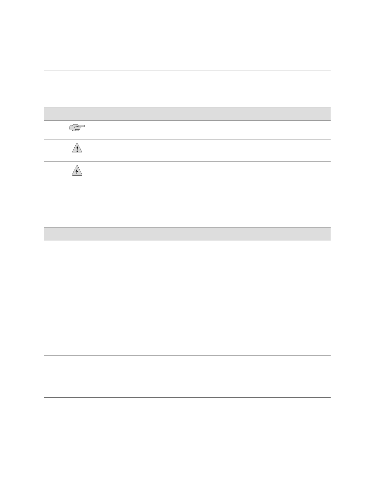
Table 1: Notice Icons
DescriptionMeaningIcon
Indicates important features or instructions.Informational note
Caution
Table 2 on page xviii defines the text and syntax conventions used in this guide.
Table 2: Text and Syntax Conventions
Bold sans serif typeface
Fixed-width typeface
Italic typeface
Indicates a situation that might result in loss of data or hardware
damage.
Alerts you to the risk of personal injury or death.Warning
Represents text that you type.
Represents output that appears on the
terminal screen.
Introduces important new terms.
■
Identifies book names.
■
Identifies RFC and Internet draft
■
titles.
ExamplesDescriptionConvention
To enter configuration mode, type the
configure command:
user@host> configure
user@host> show chassis alarms
No alarms currently active
A policy term is a named structure
■
that defines match conditions and
actions.
JUNOS System Basics Configuration
■
Guide
Italic sans serif typeface
xviii ■ Documentation Conventions
Represents variables (options for which
you substitute a value) in commands or
configuration statements.
RFC 1997, BGP Communities
■
Attribute
Configure the machine’s domain name:
[edit]
root@# set system domain-name
domain-name
Page 19

Table 2: Text and Syntax Conventions (continued)
About This Guide
ExamplesDescriptionConvention
Sans serif typeface
| (pipe symbol)
# (pound sign)
[ ] (square brackets)
Indention and braces ( { } )
; (semicolon)
Represents names of configuration
statements, commands, files, and
directories; IP addresses; configuration
hierarchy levels; or labels on routing
platform components.
Enclose optional keywords or variables.< > (angle brackets)
Indicates a choice between the mutually
exclusive keywords or variables on either
side of the symbol. The set of choices is
often enclosed in parentheses for clarity.
Indicates a comment specified on the
same line as the configuration statement
to which it applies.
Enclose a variable for which you can
substitute one or more values.
Identify a level in the configuration
hierarchy.
Identifies a leaf statement at a
configuration hierarchy level.
To configure a stub area, include
■
the stub statement at the [edit
protocols ospf area area-id]
hierarchy level.
The console port is labeled
■
CONSOLE.
stub <default-metric metric>;
broadcast | multicast
(string1 | string2 | string3)
rsvp { # Required for dynamic MPLS only
community name members [
community-ids ]
[edit]
routing-options {
static {
route default {
nexthop address;
retain;
}
}
}
J-Web GUI Conventions
Bold typeface
> (bold right angle bracket)
List of Technical Publications
Table 3 on page xx lists the software and hardware guides and release notes for
Juniper Networks J-series, M-series, MX-series, and T-series routing platforms and
Represents J-Web graphical user
interface (GUI) items you click or select.
Separates levels in a hierarchy of J-Web
selections.
In the Logical Interfaces box, select
■
All Interfaces.
To cancel the configuration, click
■
Cancel.
In the configuration editor hierarchy,
select Protocols>Ospf.
List of Technical Publications ■ xix
Page 20

M10i Internet Router Hardware Guide
describes the contents of each document. Table 4 on page xxiii lists the books included
in the Network Operations Guide series.
Table 3: Technical Documentation for Supported Routing Platforms
DescriptionBook
JUNOS Internet Software for Supported Routing Platforms
Class of Service
Provides an overview of the class-of-service (CoS) functions of the
JUNOS software and describes how to configure CoS features,
including configuring multiple forwarding classes for transmitting
packets, defining which packets are placed into each output queue,
scheduling the transmission service level for each queue, and
managing congestion through the random early detection (RED)
algorithm.
CLI User Guide
Feature Guide
MPLS Applications
Multicast Protocols
Network Interfaces
Network Management
Policy Framework
Routing Protocols
Secure Configuration Guide for Common Criteria
and JUNOS-FIPS
Describes how to use the JUNOS command-line interface (CLI) to
configure, monitor, and manage Juniper Networks routing
platforms. This material was formerly covered in the JUNOS System
Basics Configuration Guide.
Provides a detailed explanation and configuration examples for
several of the most complex features in the JUNOS software.
Provides an overview of traffic engineering concepts and describes
how to configure traffic engineering protocols.
Provides an overview of multicast concepts and describes how to
configure multicast routing protocols.
Provides an overview of the network interface functions of the
JUNOS software and describes how to configure the network
interfaces on the routing platform.
Provides an overview of network management concepts and
describes how to configure various network management features,
such as SNMP and accounting options.
Provides an overview of policy concepts and describes how to
configure routing policy, firewall filters, and forwarding options.
Provides an overview of routing concepts and describes how to
configure routing, routing instances, and unicast routing protocols.
Provides an overview of secure Common Criteria and JUNOS-FIPS
protocols for the JUNOS Internet software and describes how to
install and configure secure Common Criteria and JUNOS-FIPS on
a routing platform.
Services Interfaces
Software Installation and Upgrade Guide
xx ■ List of Technical Publications
Provides an overview of the services interfaces functions of the
JUNOS software and describes how to configure the services
interfaces on the router.
Provides a description of JUNOS software components and
packaging, and includes detailed information about how to initially
configure, reinstall, and upgrade the JUNOS system software. This
material was formerly covered in the JUNOS System Basics
Configuration Guide.
Page 21

Table 3: Technical Documentation for Supported Routing Platforms (continued)
DescriptionBook
About This Guide
System Basics
VPNs
JUNOS References
Hierarchy and RFC Reference
Interfaces Command Reference
Routing Protocols and Policies Command
Reference
System Basics and Services Command Reference
Describes Juniper Networks routing platforms, and provides
information about how to configure basic system parameters,
supported protocols and software processes, authentication, and
a variety of utilities for managing your router on the network.
Provides an overview and describes how to configure Layer 2 and
Layer 3 virtual private networks (VPNs), virtual private LAN service
(VPLS), and Layer 2 circuits. Provides configuration examples.
Describes the JUNOS configuration mode commands. Provides a
hierarchy reference that displays each level of a configuration
hierarchy, and includes all possible configuration statements that
can be used at that level. This material was formerly covered in
the JUNOS System Basics Configuration Guide.
Describes the JUNOS software operational mode commands you
use to monitor and troubleshoot interfaces.
Describes the JUNOS software operational mode commands you
use to monitor and troubleshoot routing policies and protocols,
including firewall filters.
Describes the JUNOS software operational mode commands you
use to monitor and troubleshoot system basics, including
commands for real-time monitoring and route (or path) tracing,
system software management, and chassis management. Also
describes commands for monitoring and troubleshooting services
such as class of service (CoS), IP Security (IPSec), stateful firewalls,
flow collection, and flow monitoring.
System Log Messages Reference
J-Web User Guide
J-Web Interface User Guide
JUNOS API and Scripting Documentation
JUNOScript API Guide
JUNOS XML API Configuration Reference
JUNOS XML API Operational Reference
NETCONF API Guide
Describes how to access and interpret system log messages
generated by JUNOS software modules and provides a reference
page for each message.
Describes how to use the J-Web graphical user interface (GUI) to
configure, monitor, and manage Juniper Networks routing
platforms.
Describes how to use the JUNOScript application programming
interface (API) to monitor and configure Juniper Networks routing
platforms.
Provides reference pages for the configuration tag elements in the
JUNOS XML API.
Provides reference pages for the operational tag elements in the
JUNOS XML API.
Describes how to use the NETCONF API to monitor and configure
Juniper Networks routing platforms.
List of Technical Publications ■ xxi
Page 22

M10i Internet Router Hardware Guide
Table 3: Technical Documentation for Supported Routing Platforms (continued)
DescriptionBook
JUNOS Configuration and Diagnostic Automation
Guide
Hardware Documentation
Hardware Guide
PIC Guide
JUNOScope Documentation
JUNOScope Software User Guide
J-series Routing Platform Documentation
Getting Started Guide
Describes how to use the commit script and self-diagnosis features
of the JUNOS software. This guide explains how to enforce custom
configuration rules defined in scripts, how to use commit script
macros to provide simplified aliases for frequently used
configuration statements, and how to configure diagnostic event
policies.
Describes how to install, maintain, and troubleshoot routing
platforms and components. Each platform has its own hardware
guide.
Describes the routing platform's Physical Interface Cards (PICs).
Each platform has its own PIC guide.
Describes the JUNOScope software graphical user interface (GUI),
how to install and administer the software, and how to use the
software to manage routing platform configuration files and monitor
routing platform operations.
Provides an overview, basic instructions, and specifications for
J-series routing platforms. The guide explains how to prepare your
site for installation, unpack and install the router and its
components, install licenses, and establish basic connectivity. Use
the Getting Started Guide for your router model.
Basic LAN and WAN Access Configuration Guide
Advanced WAN Access Configuration Guide
Administration Guide
Release Notes
JUNOS Release Notes
Hardware Release Notes
Explains how to configure the interfaces on J-series Services Routers
for basic IP routing with standard routing protocols, ISDN backup,
and digital subscriber line (DSL) connections.
Explains how to configure J-series Services Routers in virtual private
networks (VPNs) and multicast networks, configure data link
switching (DLSw) services, and apply routing techniques such as
policies, stateless and stateful firewall filters, IP Security (IPSec)
tunnels, and class-of-service (CoS) classification for safer, more
efficient routing.
Shows how to manage users and operations, monitor network
performance, upgrade software, and diagnose common problems
on J-series Services Routers.
Summarize new features and known problems for a particular
software release, provide corrections and updates to published
JUNOS, JUNOScript, and NETCONF manuals, provide information
that might have been omitted from the manuals, and describe
upgrade and downgrade procedures.
Describe the available documentation for the routing platform and
summarize known problems with the hardware and accompanying
software. Each platform has its own release notes.
xxii ■ List of Technical Publications
Page 23

Table 3: Technical Documentation for Supported Routing Platforms (continued)
DescriptionBook
About This Guide
JUNOScope Release Notes
Contain corrections and updates to the published JUNOScope
manual, provide information that might have been omitted from
the manual, and describe upgrade and downgrade procedures.
J-series Services Router Release Notes
Briefly describe Services Router features, identify known hardware
problems, and provide upgrade and downgrade instructions
Table 4: JUNOS Internet Software Network Operations Guides
DescriptionBook
Baseline
Describes the most basic tasks for running a network using Juniper
Networks products. Tasks include upgrading and reinstalling JUNOS
software, gathering basic system management information,
verifying your network topology, and searching log messages.
Interfaces
Describes tasks for monitoring interfaces. Tasks include using
loopback testing and locating alarms.
MPLS
Describes tasks for configuring, monitoring, and troubleshooting
an example MPLS network. Tasks include verifying the correct
configuration of the MPLS and RSVP protocols, displaying the status
and statistics of MPLS running on all routing platforms in the
network, and using the layered MPLS troubleshooting model to
investigate problems with an MPLS network.
MPLS Log Reference
Describes MPLS status and error messages that appear in the output
of the show mpls lsp extensive command. The guide also describes
how and when to configure Constrained Shortest Path First (CSPF)
and RSVP trace options, and how to examine a CSPF or RSVP
failure in a sample network.
Hardware
Documentation Feedback
We encourage you to provide feedback, comments, and suggestions so that we can
improve the documentation. You can send your comments to
techpubs-comments@juniper.net, or fill out the documentation feedback form at
http://www.juniper.net/techpubs/docbug/docbugreport.html. If you are using e-mail, be
sure to include the following information with your comments:
■ Document name
■ Document part number
■ Page number
■ Software release version
Describes tasks for monitoring M-series and T-series routing
platforms.
Documentation Feedback ■ xxiii
Page 24

M10i Internet Router Hardware Guide
Requesting Support
For technical support, open a support case with the Case Manager link at
http://www.juniper.net/support/ or call 1-888-314-JTAC (from the United States, Canada,
or Mexico) or 1-408-745-9500 (from elsewhere).
xxiv ■ Requesting Support
Page 25

Part 1
Product Overview
■ System Overview on page 3
■ Hardware Component Overview on page 7
■ JUNOS Internet Software Overview on page 25
■ System Architecture Overview on page 33
Product Overview ■ 1
Page 26

M10i Internet Router Hardware Guide
2 ■ Product Overview
Page 27

Chapter 1
System Overview
This chapter provides an overview of the Juniper Networks M10i Internet router,
discussing the following topics:
■ System Description on page 3
■ Field-Replaceable Units (FRUs) on page 3
■ System Redundancy on page 4
■ Safety Requirements, Warnings, and Guidelines on page 5
System Description
The M10i Internet router provides high-speed interfaces for medium and large
networks and network applications, such as those supported by Internet service
providers (ISPs). Application-specific integrated circuits (ASICs), a definitive part of
the router design, enable the router to forward data at the high speeds demanded
by current network media.
The M10i router supports up to eight Physical Interface Cards (PICs). The router
height of 8.7 in. (22.1 cm) enables stacked installation of eight M10i routers in a
single floor-to-ceiling rack, for increased port density per unit of floor space.
The router's maximum aggregate throughput is 3.2 gigabits per second (Gbps) full
duplex per FPC (6.4 Gbps full-duplex total throughput rate). Inserting a combination
of PICs with an aggregate higher than the maximum throughput per FPC is supported,
but constitutes oversubscription of the FPC.
The router architecture cleanly separates control operations from packet forwarding
operations, which helps to eliminate processing and traffic bottlenecks. Control
operations in the router are performed by the Routing Engine, which runs JUNOS
Internet software to handle routing protocols, traffic engineering, policy, policing,
monitoring, and configuration management. Forwarding operations in the router
are performed by the Packet Forwarding Engine, which consists of hardware, including
ASICs, designed by Juniper Networks.
Field-Replaceable Units (FRUs)
Field-replaceable units (FRUs) are router components that can be replaced at the
customer site. Replacing most FRUs requires minimal router downtime. The router
uses the following types of FRUs:
System Description ■ 3
Page 28

M10i Internet Router Hardware Guide
■ Hot-removable and hot-insertable FRUs—You can remove and replace these
■ Hot-pluggable FRUs—You can remove and replace these components without
■ FRUs that require powering off the router—You must power off the router before
Table 5 on page 4 lists the FRUs for the M10i router.
Table 5: Field-Replaceable Units
components without powering off the router or disrupting the routing functions.
powering off the router, but the routing functions of the system are interrupted
when the component is removed. If a component is acting as a backup, it can
be removed without affecting router functions.
removing these components.
Hot-Removable and
Hot-Insertable FRUs
Fan tray
Physical Interface Card
(PIC)
Power supply (AC or DC)
Small form-factor pluggable
(SFP)
For FRU replacement instructions, see “Replacing Hardware Components” on page 87.
System Redundancy
You can configure the router for system redundancy by using three AC or four DC
load-sharing, fully-redundant power supplies to distribute power to the other
components.
AC System Redundancy
AC system redundancy requires three independent AC power outlets. If one power
supply fails, the other two power supplies provide full power to the router's
components indefinitely.
FRUs that require
powering off the routerHot-Pluggable FRUs
NoneCompact Forwarding
Engine Board (CFEB)
High-Availability Chassis
Manager (HCM)
Routing Engine
4 ■ System Redundancy
You can set up increased AC system redundancy by using four AC power supplies.
In this case, two power supplies are powered from two AC outlets, and the other two
power supplies use two AC outlets from a UPS battery-backed power source. This
lets the router run during AC power outages for the amount of time that the UPS
allows.
Page 29

DC System Redundancy
DC system redundancy requires two power sources from feed A and two power
sources from feed B. If one feed fails or is shut down for service, the other feed
powers two DC power supplies and can provide full power to the router's components
indefinitely.
Safety Requirements, Warnings, and Guidelines
To avoid harm to yourself or the router as you install and maintain it, you need to
follow the guidelines for working with and near electrical equipment, as well as the
safety procedures for working with Internet routers. For a discussion of how to make
the installation site a safe environment, see “Preparing for Router
Installation” on page 41. For a list of safety warnings, see “Safety and Regulatory
Compliance Information” on page 135 and particularly “Electrical Safety Guidelines and
Warnings” on page 142. However, providing an exhaustive set of guidelines for working
with electrical equipment is beyond the scope of this manual.
Chapter 1: System Overview
Safety Requirements, Warnings, and Guidelines ■ 5
Page 30

M10i Internet Router Hardware Guide
6 ■ Safety Requirements, Warnings, and Guidelines
Page 31

Chapter 2
Hardware Component Overview
This chapter provides an overview of the hardware components on the M10i Internet
router:
■ Router Chassis on page 7
■ Midplane on page 9
■ Flexible PIC Concentrators (FPCs) on page 10
■ Physical Interface Cards (PICs) on page 10
■ Compact Forwarding Engine Board (CFEB) on page 11
■ Routing Engine on page 14
■ High-Availability Chassis Manager (HCM) on page 17
■ Power Supplies on page 19
■ Fan Tray on page 23
■ Cable Management System on page 23
Router Chassis
The router chassis is a rigid sheet metal structure that houses the other hardware
components. The chassis is 17.5 in. (44.5 cm) wide and 18 in. (45.7 cm) deep. The
chassis height of 8.7 in. (22.1 cm) enables stacked installation of eight M10i routers
in a single floor-to-ceiling rack. For more information, see “Rack
Requirements” on page 42.
The two mounting brackets (one on each side) extend the chassis width to 19 in.
(48.3 cm).
Figure 1 and Figure 2 show front and rear views of the router chassis.
Router Chassis ■ 7
Page 32

M10i Internet Router Hardware Guide
Figure 1: Front of Chassis
Figure 2: Rear of Chassis
8 ■ Router Chassis
The chassis includes an electrostatic discharge (ESD) point (banana plug receptacle)
to protect electronic components from damage due to static electricity, at the front
of the chassis, as shown in Figure 1.
WARNING: Before removing or installing components of a functioning router, attach
an ESD strap to an ESD point and place the other end of the strap around your bare
wrist. Failure to use an ESD strap could result in damage to the router.
The router must be connected to earth ground during normal operation.
Page 33

For further safety information, see “Safety and Regulatory Compliance
Information” on page 135.
Table 6 on page 9 summarizes physical specifications for the router chassis.
Table 6: Chassis Physical Specifications
ValueDescription
8.7 in. (22.1 cm)Chassis height
Chapter 2: Hardware Component Overview
Midplane
Chassis width
Thermal output
The midplane is a panel located in the center of the chassis, running from side to
side and forming the rear of the PIC card cage (see Figure 3). All router components
plug directly into the midplane. The midplane contains an EEPROM that stores the
serial number and revision level of the midplane.
The midplane performs the following functions:
■ Transfer of packets—After being processed by a PIC, an incoming data packet
17.5 in. (44.5 cm) for sides of chassis
■
19 in. (48.3 cm) with mounting brackets
■
18 in. (45.7 cm)Chassis depth
79 lb (35.8 kg)Weight, maximum configuration
57 lb (25.9 kg)Weight, minimum configuration
AC: 3276 BTU/hour (960 W)
■
DC: 1965 BTU/hour (576 W)
■
crosses the midplane to the CFEB. The CFEB performs switching and forwarding
functions and transfers outgoing packets back across the midplane to the PICs
for transmission to the network.
■ Power distribution—The midplane distributes power to all router components
from the power supplies attached to it. It also provides hot-plug protection for
the PIC and HCM slots.
■ Signal connectivity—The midplane transports the signals exchanged by system
components for monitoring and control purposes.
Midplane ■ 9
Page 34

M10i Internet Router Hardware Guide
Figure 3: Midplane
Flexible PIC Concentrators (FPCs)
Flexible PIC Concentrators (FPCs) house the PICs that connect the router to network
media (for information about PICs, see “Physical Interface Cards (PICs)” on page 10).
On the M10i router, each FPC is built in (it cannot be removed from the chassis as
on other M-series platforms) and corresponds to a horizontal row of PIC slots. The
two FPCs on the M10i router are numbered 0 and 1, top to bottom. Each FPC
accommodates up to four PICs.
Physical Interface Cards (PICs)
Physical Interface Cards (PICs) physically connect the router to network media. They
are housed in Flexible PIC Concentrators (FPCs); for more information about FPCs,
see “Flexible PIC Concentrators (FPCs)” on page 10.
PICs receive incoming packets from the network and transmit outgoing packets to
the network, performing framing and line-speed signaling for their media type as
required. PICs also encapsulate outgoing packets received from the FPCs before
transmitting them. The controller ASIC on each PIC performs additional control
functions specific to the PIC media type.
The router supports various PICs, including ATM, Channelized, Gigabit Ethernet, IP
Services, and SONET/SDH interfaces. For complete PIC specifications, see the M10i
Internet Router PIC Guide.
Some PICs, such as selected Gigabit Ethernet PICs, accept small form-factor pluggables
(SFPs), which are fiber-optic transceivers that can be removed from the PIC. Various
SFPs have different reach characteristics. You can mix them in a single PIC and
change the combination dynamically. SFPs are hot-removable and hot-insertable, as
described in “Field-Replaceable Units (FRUs)” on page 3. For SFP replacement
instructions, see “Replacing an SFP” on page 104. For information about PICs that use
SFPs, see the M10i Internet Router PIC Guide.
Up to eight PICs install into an M10i router, as shown in Figure 1. The PIC slots on
the upper FPC are numbered from 0/0 (zero/zero) through 0/3, right to left. The PIC
slots in the lower FPC are numbered from 1/0 (one/zero) through 1/3, right to left.
10 ■ Flexible PIC Concentrators (FPCs)
Page 35

PIC Components
Chapter 2: Hardware Component Overview
The slot number for a PIC appears above its offline button on the HCM (see “PIC
Offline Buttons” on page 19). The number of ports on a PIC depends on the type of
PIC.
PICs are hot-removable and hot-insertable. A removed PIC no longer receives or
transmits data, and removing or inserting a PIC briefly interrupts forwarding of traffic
through the remaining PICs.
For PIC replacement instructions, see “Replacing a PIC” on page 96.
Most PICs supported on the M10i router have the following components. For complete
specifications, see the M10i Internet Router PIC Guide. For information about pinouts
for PIC cable connectors, see “Cable Connector Pinouts” on page 199.
■ One or more cable connector ports—Accept a network media connector.
■
LEDs—Indicate PIC and port status. Most PICs have an LED labeled STATUS on
the PIC faceplate. Some PICs have additional LEDs, often one per port. The
meaning of the LED states differs for various PICs. For more information, see
the M10i Internet Router PIC Guide.
■ Ejector lever—Controls the locking system that secures the PIC in the card cage.
Compact Forwarding Engine Board (CFEB)
The Compact Forwarding Engine Board (CFEB) performs route lookup, filtering, and
switching on incoming data packets, then directs outbound packets to the appropriate
FPC for transmission to the network. It can process 16 million packets per second
(Mpps).
One or two CFEBs can be installed into the midplane from the rear of the chassis,
as shown in Figure 2. Only one CFEB is active at a time; the optional second CFEB
is in standby mode. By default, the CFEB in slot CFEB 0 is active. To modify the
default, include the appropriate cfeb statement at the [edit chassis redundancy]
hierarchy level of the configuration, as described in the section about CFEB
redundancy in the JUNOS System Basics Configuration Guide.
CFEBs are hot-pluggable, as described in “Field-Replaceable Units (FRUs)” on page 3.
Removing the standby CFEB has no effect on router function. If the active CFEB fails
or is removed from the chassis, the effect depends on how many CFEBs are installed:
■ If there is one CFEB, forwarding halts until the CFEB is replaced and functioning
again. It takes approximately one minute for the replaced CFEB to boot and
become active; reading in router configuration information can take additional
time, depending on the complexity of the configuration.
■ If there are two CFEBs, forwarding halts while the standby CFEB boots and
becomes active, which takes approximately one minute; synchronizing router
configuration information can take additional time, depending on the complexity
of the configuration.
Compact Forwarding Engine Board (CFEB) ■ 11
Page 36

M10i Internet Router Hardware Guide
For CFEB replacement instructions, see “Replacing a CFEB” on page 90.
The CFEB communicates with the Routing Engine using a dedicated 100-Mbps Fast
Ethernet link that transfers routing table data from the Routing Engine to the
forwarding table in the integrated ASIC. The link is also used to transfer from the
CFEB to the Routing Engine routing link-state updates and other packets destined
for the router that have been received through the router interfaces.
The ASICs and other components on the CFEB provide the following functions:
■ Route lookups—Performs route lookups using the forwarding table stored in the
■ Management of shared memory —Uniformly allocates incoming data packets
■ Transfer of outgoing data packets—Passes data packets to the destination FIC
synchronous SRAM (SSRAM).
throughout the router's shared memory.
or PIC when the data is ready to be transmitted.
CFEB Components
■ Transfer of exception and control packets—Passes exception packets to the
microprocessor on the CFEB, which processes almost all of them. The remainder
are sent to the Routing Engine for further processing. Any errors originating in
the Packet Forwarding Engine and detected by the CFEB are sent to the Routing
Engine using system log messages.
The CFEB has the following major components:
■ Processing components:
■ 266-MHz CPU and supporting circuitry
■ Integrated ASIC
■ 33-MHz PCI bus
■ Storage components:
■ SDRAM for packet memory
■ SDRAM for the microkernel
■ SSRAM for route lookup
■ SSRAM for control memory
■ System interfaces:
■ 100-Mbps Ethernet link for internal interface to the Routing Engine
■ 19.44-MHz reference clock that generates clock signal for SONET/SDH PICs
2
■ I
C controller to read the I2C/EEPROMs in the PICs and temperature sensors
12 ■ Compact Forwarding Engine Board (CFEB)
Page 37

Chapter 2: Hardware Component Overview
2
■ I
C/EEPROM containing the serial number and revision level
■ Two 512-KB boot flash EPROMs (programmable on the board)
■ One PowerPC 8245 integrated processor
■
Three LEDs—A green LED labeled OK, a red LED labeled FAIL, and a blue LED
labeled MASTER indicate CFEB status. Table 7 on page 13 describes the LED
states.
■ Power off button—Prepares the CFEB for removal from the router when pressed.
■ Ejector levers—Control the locking system that secures the CFEB in the chassis.
NOTE: For specific information about CFEB components (for example, the amount
of SDRAM), issue the show chassis cfeb command.
Figure 4: CFEB
Table 7: States for CFEB LEDs
OK
FAIL
DescriptionStateColorLabel
CFEB is running normally.On steadilyGreen
CFEB is starting up.Blinking
CFEB is not operational or is in reset mode.On steadilyRed
MASTER
CFEB is functioning as master.On steadilyBlue
Compact Forwarding Engine Board (CFEB) ■ 13
Page 38

M10i Internet Router Hardware Guide
Routing Engine
The Routing Engine is an Intel-based PCI platform that runs JUNOS Internet software.
Software processes that run on the Routing Engine maintain the routing tables,
manage the routing protocols used on the router, control the router's interfaces,
control some chassis components, and provide the interface for system management
and user access to the router.
For a description of the Routing Engine's role in router architecture, see “Routing
Engine Architecture” on page 35.
One or two Routing Engines can be installed into the midplane from the front of the
chassis, as shown in Figure 1. If two Routing Engines are installed, the High-Availability
Chassis Manager (HCM) determines which is the master and which is in standby
mode (and so performs no functions). By default, the Routing Engine in the slot
labeled RE0 is the master.
To change the default master Routing Engine, include the appropriate
[edit chassis redundancy routing-engine] statement in the configuration, as described
in the section about Routing Engine redundancy in the JUNOS System Basics
Configuration Guide.
The Routing Engine is hot-pluggable, as described in “Field-Replaceable Units
(FRUs)” on page 3. Removal or failure of the standby Routing Engine does not affect
router function. If the master Routing Engine is removed from the chassis, the effect
depends on whether two Routing Engines are installed:
■ With the default router configuration, in case of failure you must correct the
problem manually. You can issue the appropriate
request chassis routing-engine master command to switch mastership to the other
Routing Engine, for example. For information about the command, see the JUNOS
System Basics and Services Command Reference.
■ On routers with two installed Routing Engines, you can configure graceful
switchover of Routing Engines or automatic Routing Engine mastership failover.
If the Routing Engines are configured for graceful switchover, the standby Routing
Engine immediately assumes Routing Engine functions and there is no
interruption to packet forwarding. Otherwise, packet forwarding halts while the
standby Routing Engine becomes the master and the Packet Forwarding Engine
components reset and connect to the new master Routing Engine. For information
about configuring graceful switchover or automatic mastership failover, see the
section about Routing Engine redundancy in the JUNOS System Basics
Configuration Guide.
We recommend you run JUNOS Release 7.0 or later on the M10i router to support
graceful switchover.
For replacement instructions, see “Replacing the Routing Engine” on page 121.
Routing Engine Components
The Routing Engine has the following major components (see Figure 5):
14 ■ Routing Engine
Page 39

Chapter 2: Hardware Component Overview
■ CPU—Runs JUNOS Internet software to maintain the router's routing tables and
routing protocols. It has a Pentium-class processor.
■ SDRAM—Provides storage for the routing and forwarding tables and for other
Routing Engine processes.
■ Internal flash drive—This drive is optional. If installed, it provides primary storage.
It holds software images, configuration files, and microcode.
■ Hard disk—If no internal flash drive is installed, provides primary storage for
software images, configuration files, and microcode. If an internal flash drive is
installed, the hard disk provides secondary storage for log files and memory
dumps, and can reboot the system if the internal flash drive fails.
■ PC card slot—Accepts a removable PC card, which stores software images for
system upgrades.
■
Four LEDs—A green LED labeled HDD, a blue LED labeled MASTER, a red LED
labeled FAIL, and a green LED labeled ONLINE indicate Routing Engine status.
Table 8 on page 16 describes the LED states.
■ Interfaces for out-of-band management access—Provide information about
Routing Engine status to devices (console, laptop, or terminal server) that can
be attached to access ports located on the Routing Engine.
2
■ I
C/EEPROM—Stores the serial number of the Routing Engine.
■ Reset button—Reboots the Routing Engine when pressed.
■ Offline button—Powers down the Routing Engine when pressed.
■ Thumbscrews—Secure the Routing Engine in the chassis.
NOTE: The appearance and position of electronic components or the PC card slot
on your Routing Engine might differ from Figure 5 and other figures in this document
that depict the Routing Engine. These differences do not affect Routing Engine
installation and removal or functionality.
NOTE: For specific information about Routing Engine components (for example, the
capacity of the hard drive), issue the show chassis routing-engine command.
Routing Engine ■ 15
Page 40

M10i Internet Router Hardware Guide
Figure 5: Routing Engine
Table 8: States for Routing Engine LEDs
HDD
MASTER
FAIL
ONLINE
Routing Engine Interface Ports
Each Routing Engine has a set of ports for connecting to one or more external devices
on which system administrators can issue JUNOS command-line interface (CLI)
commands to manage the router (see Figure 5).
The ports with the indicated label in each set function as follows:
■
AUX/MODEM— Connects the Routing Engine to a laptop, modem, or other
auxiliary device through an RS-232 (EIA-232) serial cable.
■
MGMT—Connects the Routing Engine through an Ethernet connection to a
management LAN (or any other device that plugs into an Ethernet connection)
for out-of-band management. The port uses an autosensing RJ-45 connector to
support both 10- and 100-Mbps connections.
DescriptionStateColorLabel
There is read/write activity on the PC card.BlinkingGreen
Routing Engine is functioning as master.On steadilyBlue
Routing Engine is not operational.On steadilyRed
Routing Engine is running normally.On steadilyGreen
16 ■ Routing Engine
To the left of each MGMT port is a link status indicator, which lights to show that
a link has been established over the Ethernet connection. To the right of each
MGMT port is an activity indicator, which flashes when data is being transferred.
■
CONSOLE—Connects the Routing Engine to a system console through an RS-232
(EIA-232) serial cable.
Page 41

For information about the pinouts for the connectors, see “Cable Connector
Pinouts” on page 199.
High-Availability Chassis Manager (HCM)
The High-Availability Chassis Manager (HCM) works with its companion Routing
Engine to provide control and monitoring functions for router components. The HCM
also displays alarm status and takes PICs online and offline.
Two HCMs are installed into the midplane from the front of the chassis, as shown
in Figure 1. The master HCM performs all functions and provides PIC removal buttons
for the first FPC. The standby HCM provides PIC removal buttons for the second FPC.
The HCM in the slot labeled HCM0 is paired with the Routing Engine in the slot labeled
RE0. Likewise, the HCM in the slot labeled HCM1 is paired with the Routing Engine
in the slot labeled RE1. By default, the HCM in the slot labeled HCM0 is the master.
NOTE: When HCM mastership changes because of failure, Routing Engine mastership
will change as well. For a description of Routing Engine mastership, see “Routing
Engine” on page 14.
Chapter 2: Hardware Component Overview
HCM Components
The HCM performs the following functions:
■ Monitoring and control of router components—The HCM collects statistics from
all sensors in the system. When it detects a failure or alarm condition, it sends
a signal to the Routing Engine, which generates control messages or sets an
alarm. The HCM also relays control messages from the Routing Engine to the
router components.
■ Controlling component power-up and power-down—The HCM controls the
power-up sequence of router components as they start and powers down
components when their offline buttons are pressed.
■ Signaling of mastership—In a router with more than one Routing Engine, the
HCM signals to all router components which Routing Engine is the master and
which is the standby.
■ Alarm display—If an alarm exists, the HCM displays the alarm condition. For
more information, see “Alarm LEDs” on page 18.
■ PIC removal—If a PIC offline button is pressed, the HCM relays the request to
the CFEB, which takes the PIC offline and informs the Routing Engine. Other
PICs are unaffected, and system operation continues. For more information, see
“PIC Offline Buttons” on page 19.
Each HCM (shown in Figure 6) has the following components:
High-Availability Chassis Manager (HCM) ■ 17
Page 42

M10i Internet Router Hardware Guide
■ 100-Mbps Fast Ethernet switch—Carries signals and monitoring data between
■
■ Alarm LEDs—Display alarm conditions, if any exist.
■ PIC offline buttons—Relays a request to the CFEB, which prepares a PIC for
Figure 6: High-Availability Chassis Manager
router components.
Two LEDs—Indicate HCM status. There is a green one labeled PWR and an blue
one labeled MSTR. Table 9 on page 18 describes the LED states.
removal from the router, or brings the PIC online when it is replaced.
Table 9: States for HCM LEDs
PWR
MSTR
Alarm LEDs
Two alarm LEDs are located on the right of the HCM (see Figure 6). The circular red
LED lights to indicate a critical condition that can result in a system shutdown. The
triangular yellow LED lights to indicate a less severe condition that requires monitoring
or maintenance. Both LEDs can be lit simultaneously.
To deactivate red and yellow alarms, you must clear the condition that caused the
alarm.
DescriptionStateColorLabel
HCM is functioning normally.On steadilyGreen
HCM is starting up.Blinking
HCM is master.On steadilyBlue
18 ■ High-Availability Chassis Manager (HCM)
Page 43

Table 10 on page 19 describes the alarm LEDs in more detail.
Table 10: Alarm LEDs
Chapter 2: Hardware Component Overview
DescriptionStateColorShape
Power Supplies
On steadilyRed
On steadilyYellow
Critical alarm LED—Indicates a critical condition
that can cause the router to stop functioning, such
as component removal, failure, or overheating.
Warning alarm LED—Indicates a serious but nonfatal
error condition, such as a maintenance alert or a
significant increase in component temperature.
PIC Offline Buttons
Offline buttons for one row of PICs are located on each HCM (see Figure 6). Pressing
the button relays a request to the CFEB, which prepares the PIC for removal from
the router, or brings it online when it is replaced. The HCM in slot 0 controls PICs
on FPC 0. The HCM in slot 1 controls PICs on FPC 1. The buttons are labeled with
the PIC slot numbers. The PIC slots on the upper FPC are numbered from 0/0
(zero/zero) through 0/3, right to left. The PIC slots in the lower FPC are numbered
from 1/0 (one/zero) through 1/3, right to left.
For PIC replacement instructions, see “Replacing a PIC” on page 96.
The router uses either AC or DC power. You can install up to four load-sharing power
supplies at the bottom rear of the chassis, as shown in Figure 2. The power supplies
connect to the midplane, which distributes power to router components according
to their individual voltage requirements. When the power supplies are installed and
operational, they automatically share the electrical load.
An enable control pin on the output connector of each power supply ensures that
the supply is fully seated into the router midplane before the supply can be turned
on. The enable pin prevents a user-accessible energy hazard, so there is no
interlocking mechanism. The enable pin disables the voltage at the output connector
if the power supply is not turned off before removal.
The router must have at least two AC power supplies, and any two AC power supplies
can provide full power to the router. Three power supplies are required for
redundancy.
The router must have at least two DC power supplies, and any two DC power supplies
can provide full power to the router. DC system redundancy requires two power
sources from feed A and two power sources from feed B. If one feed fails or is shut
down for service, the other feed powers two DC power supplies and can provide full
power to the router's components indefinitely.
Power Supplies ■ 19
Page 44

M10i Internet Router Hardware Guide
Power supplies are hot-removable and hot-insertable, as described in “Field-Replaceable
Units (FRUs)” on page 3. To avoid electrical injury, carefully follow the instructions
in “Replacing an AC Power Supply” on page 107 and “Replacing a DC Power
Supply” on page 112.
NOTE: After powering off a power supply, wait at least 60 seconds before turning it
back on. After powering on a power supply, wait at least 60 seconds before turning
it off.
If the router is completely powered off when you power on the power supply, the
Routing Engine boots as the power supply completes its startup sequence. If the
Routing Engine finishes booting and you need to power off the router again, first
issue the CLI request system halt command. For more information, see “Disconnecting
AC Power from the Router” on page 111 or “Disconnecting DC Power from the
Router” on page 117.
After a power supply is powered on, it can take up to 60 seconds for status
indicators—such as LEDs on the power supply and show chassis commands—to
indicate that the power supply is functioning normally. Ignore error indicators that
appear during the first 60 seconds.
AC Power Supply
See the following sections for further information about power system components:
■ AC Power Supply on page 20
■ DC Power Supply on page 21
■ Power Supply LED on page 22
An AC-powered router has two or more load-sharing AC power supplies, located at
the bottom rear of the chassis, as shown in Figure 2. For information about power
supply redundancy and replaceability, see “Power Supplies” on page 19.
Figure 7 shows the power supply and Table 11 on page 21 lists electrical specifications.
For information about the LED, see “Power Supply LED” on page 22.
20 ■ Power Supplies
Page 45

Figure 7: AC Power Supply
Table 11: Electrical Specifications for AC Power Supply
SpecificationDescription
Chapter 2: Hardware Component Overview
AC input voltage
Output voltages
DC Power Supply
293 WDCMaximum power output
Nominal: 100, 120, 200, 208, 220, 240 VAC
Operating range: 90–264 VAC
47–63 HzAC input line frequency
6–3 AAC input current rating
+3.3 V @ 40 A, +2.5 V @ 20 A, +5.0 V @ 15 A,
+12 V@ 3 A
A DC-powered router has two or more load-sharing DC power supplies, located at
the bottom rear of the chassis, as shown in Figure 2. For information about power
supply redundancy and replaceability, see “Power Supplies” on page 19.
Figure 8 shows the power supply and Table 12 on page 22 lists electrical specifications.
For information about the LED, see “Power Supply LED” on page 22.
Power Supplies ■ 21
Page 46

M10i Internet Router Hardware Guide
Figure 8: DC Power Supply
Table 12: Electrical Specifications for DC Power Supply
SpecificationDescription
293 WMaximum power output
DC input voltage
Output voltages
Power Supply LED
Table 13: States for Power Supply LED
Nominal: –48, –60 VDC
Operating range: –40.5 to –72 VDC
10 A @ –48 VInput DC current rating
+3.3 V @ 40 A, +2.5 V @ 20 A, +5.0 V @ 15 A,
+12 V@ 3 A
NOTE: The DC power supply requires –42 VDC to power on.
NOTE: The DC power supplies are marked –48 VDC. This is the nominal voltage
associated with the battery circuit. Any higher voltages are associated only with float
voltages for the charging function.
Table 13 on page 22 describes the LED on both AC and DC power supplies.
OUTPUT OK
22 ■ Power Supplies
On steadilyGreen
Blinking
DescriptionStateColorLabel
Power supply is functioning normally, input is
occurring, outputs are within range, and the
temperature is within range.
Power supply is not functioning, is starting up, is
not properly inserted, or airflow is not sufficient.
Page 47

Fan Tray
Chapter 2: Hardware Component Overview
The router's cooling system consists of two fan trays, located along the left and right
side of the chassis, that provide side-to-side cooling (see Figure 9). They connect
directly to the router midplane. Each fan tray is a single unit containing eight
individually fault-tolerant fans. If a single fan fails, the remaining fans continue to
function indefinitely. For proper airflow, the primary fan tray should be installed in
slot 1 (the left slot looking at the chassis from the rear) and must be installed for
proper cooling at all times. The redundant fan tray, if present, should be installed in
slot 0 on the right. This fan tray provides additional cooling and redundancy.
Figure 9: Airflow Through the Chassis
The fan tray is hot-removable and hot-insertable, as described in “Field-Replaceable
Units (FRUs)” on page 3. For instructions on replacing it, see “Replacing a Fan
Tray” on page 88.
CAUTION: Do not remove both fan trays for more than one minute while the router
is operating. The fans are the sole source of cooling, and the router can overheat
when they are absent.
Cable Management System
The cable management system consists of racks that attach vertically to each side
of the chassis at the front, as shown in Figure 10. Pass PIC cables through the slots
in the racks to keep the cables organized and securely in place, and to avoid bending
optical cables beyond the proper bend radius. The cable management system evenly
distributes the weight of a cable, so that it is not subjected to undue stress at the
connector.
Fan Tray ■ 23
Page 48

M10i Internet Router Hardware Guide
Figure 10: Cable Management System
24 ■ Cable Management System
Page 49

Chapter 3
JUNOS Internet Software Overview
The JUNOS Internet software is especially designed for the large production networks
typically supported by Internet Service Providers (ISPs). It incorporates Internet
Protocol (IP) routing software and software for management of interfaces, networks,
and the router chassis.
The JUNOS Internet software runs on the Routing Engine. The software consists of
processes that support Internet routing protocols, control the router's interfaces and
the router chassis itself, and provide an interface for system management. The
processes run on top of a kernel that coordinates the communication among processes
and has a direct link to the Packet Forwarding Engine software.
Use the JUNOS Internet software to configure the routing protocols that run on the
router and the properties of router interfaces. After you have activated a software
configuration, use the JUNOS Internet software to monitor the protocol traffic passing
through the router and to troubleshoot protocol and network connectivity problems.
For additional information about the JUNOS Internet software, including its security
features and a list of the industry standards it supports, see the JUNOS System Basics
Configuration Guide. For complete information about configuring the software,
including examples, see the JUNOS Internet software configuration guides.
NOTE: The router supports Release 6.1 and later versions of the JUNOS Internet
software.
This chapter discusses the following topics:
■ Routing Engine Software Components on page 25
■ Tools for Accessing and Configuring the Software on page 32
■ Tools for Monitoring the Software on page 32
■ Software Upgrades on page 32
Routing Engine Software Components
The Routing Engine software consists of several software processes that control
router functions and a kernel that coordinates communication among the processes,
as described in the following sections:
Routing Engine Software Components ■ 25
Page 50

M10i Internet Router Hardware Guide
■ Routing Protocol Process on page 26
■ VPNs on page 30
■ Interface Process on page 31
■ Chassis Process on page 31
■ SNMP and MIB II Processes on page 31
■ Management Process on page 31
■ Routing Engine Kernel on page 31
Routing Protocol Process
The JUNOS software routing protocol process controls the routing protocols that run
on the router. The routing protocol process starts all configured routing protocols
and handles all routing messages. It consolidates the routing information learned
from all routing protocols into common routing tables. From this routing information,
the routing protocol process determines the active routes to network destinations
and installs these routes into the Routing Engine's forwarding table. Finally, the
routing protocol process implements the routing policies you specify, which determine
how routing information is transferred between the routing protocols and the routing
table.
This section discusses the following topics:
■ IPv4 Routing Protocols on page 26
■ IPv6 Routing Protocols on page 28
■ Routing and Forwarding Tables on page 29
■ Routing Policy on page 29
For complete information about routing concepts, see the JUNOS Internet software
configuration guides.
IPv4 Routing Protocols
The JUNOS Internet software implements full IP routing functionality, providing
support for IP version 4 (IPv4). The routing protocols are fully interoperable with
existing IP routing protocols and provide the scale and control necessary for the
Internet core. The software provides support for the following routing and traffic
engineering protocols:
■ Unicast routing protocols
26 ■ Routing Engine Software Components
Page 51

Chapter 3: JUNOS Internet Software Overview
■ BGP—Border Gateway Protocol, version 4, is an Exterior Gateway Protocol
(EGP) that guarantees loop-free exchange of routing information between
routing domains (also called autonomous systems). BGP, in conjunction with
JUNOS routing policy, provides a system of administrative checks and
balances that can be used to implement peering and transit agreements.
■ ICMP—Internet Control Message Protocol router discovery is a method that
hosts can use to discover the addresses of operational routers on a subnet.
■ IS-IS—Intermediate System-to-Intermediate System is a link-state interior
gateway protocol (IGP) for IP networks that uses the shortest-path-first
algorithm (SPF algorithm, also called the Dijkstra algorithm) to determine
routes.
■ OSPF—Open Shortest Path First, version 2, is an IGP developed for IP
networks by the Internet Engineering Task Force (IETF). OSPF is a link-state
protocol that makes routing decisions based on the SPF algorithm.
■ RIP—Routing Information Protocol, version 2, is an IGP for IP networks
based on the Bellman-Ford algorithm. RIP is a distance-vector protocol. RIP
dynamically routes packets between a subscriber and a service provider
without the subscriber having to configure BGP or to participate in the service
provider’s IGP discovery process.
■ Multicast routing protocols
■ DVMRP—Distance Vector Multicast Routing Protocol is a dense-mode
(flood-and-prune) multicast routing protocol.
■ IGMP—Internet Group Management Protocol, versions 1 and 2, is used to
manage membership in multicast groups.
■ MSDP—Multicast Source Discovery Protocol enables multiple PIM sparse
mode domains to be joined. A rendezvous point (RP) in a PIM sparse mode
domain has a peering relationship with an RP in another domain, thereby
discovering multicast sources from other domains.
■ PIM sparse mode and dense mode—Protocol-Independent Multicast is a
multicast routing protocol used to route traffic to multicast groups that might
span wide-area and interdomain internetworks. In PIM sparse mode, routers
explicitly join and leave multicast groups. PIM dense mode is a
flood-and-prune protocol.
■ SAP/SDP—Session Announcement Protocol and Session Description Protocol
handle conference session announcements.
■ MPLS application protocols
■ LDP—Label Distribution Protocol provides a mechanism for distributing
labels in nontraffic-engineered applications. LDP allows routers to establish
label-switched paths (LSPs) through a network by mapping network-layer
routing information directly to data-link layer switched paths. LSPs created
Routing Engine Software Components ■ 27
Page 52

M10i Internet Router Hardware Guide
IPv6 Routing Protocols
The JUNOS Internet software implements full IP routing functionality, providing
support for IP version 6 (IPv6). The routing protocols are fully interoperable with
existing IP routing protocols and provide the scale and control necessary for the
Internet core. The software provides support for the following unicast routing
protocols:
by LDP can also traverse LSPs created by Resource Reservation Protocol
(RSVP).
■ MPLS—Multiprotocol Label Switching enables you to configure LSPs through
a network either manually or dynamically. You can control how traffic
traverses the network by directing it through particular paths, rather than
relying on an IGP's least-cost algorithm to choose a path.
■ RSVP—Resource Reservation Protocol, version 1, provides a mechanism for
engineering network traffic patterns that is independent of the shortest path
determined by a routing protocol. RSVP itself is not a routing protocol, but
is designed to operate with current and future unicast and multicast routing
protocols. JUNOS RSVP software supports dynamic signaling for MPLS LSPs.
■ BGP—Border Gateway Protocol, version 4, is an EGP that guarantees loop-free
exchange of routing information between routing domains (also called
autonomous systems). BGP, in conjunction with JUNOS routing policy, provides
a system of administrative checks and balances that can be used to implement
peering and transit agreements.
■ ICMP—Internet Control Message Protocol router discovery is a method that hosts
can use to discover the addresses of operational routers on a subnet.
■ IS-IS—Intermediate System-to-Intermediate System is a link-state interior gateway
protocol (IGP) for IP networks that uses the shortest-path-first algorithm (SPF
algorithm, also called the Dijkstra algorithm) to determine routes.
■ OSPF—Open Shortest Path First, version 3 (OSPFv3), supports version 6 of the
Internet Protocol (IPv6). The fundamental mechanisms of OSPF such as flooding,
Designated Router (DR) election, area based topologies and the Shortest Path
First (SPF) calculations remain unchanged. Some differences exist either due to
changes in protocol semantics between IPv4 and IPv6, or to handle the increased
address size of IPv6.
■ RIP—Routing Information Protocol, version 2, is an IGP for IP networks based
on the Bellman-Ford algorithm. RIP is a distance-vector protocol. RIP dynamically
routes packets between a subscriber and a service provider without the subscriber
having to configure BGP or to participate in the service provider’s IGP discovery
process.
28 ■ Routing Engine Software Components
Page 53

Chapter 3: JUNOS Internet Software Overview
Routing and Forwarding Tables
The primary function of the JUNOS routing protocol process is maintaining routing
tables and using the information in them to determine active routes to network
destinations. It copies information about the active routes into the Routing Engine's
forwarding table, which the JUNOS kernel copies to the Packet Forwarding Engine.
By default, the routing protocol process maintains the following routing tables and
uses the information in each table to determine active routes to network destinations:
■ Unicast routing table—Stores routing information for all unicast protocols running
on the router, including BGP, IS-IS, OSPF, and RIP. You can also configure
additional routes, such as static routes, for inclusion in the routing table. The
unicast routing protocols use the routes in this table when advertising routing
information to their neighbors.
In the unicast routing table, the routing protocol process designates routes with
the lowest preference values as active. By default, a route's preference value is
simply a function of how the routing protocol process learned about the route.
You can modify the default preference value by setting routing policies and
configuring other software parameters. See “Routing Policy” on page 29.
■ Multicast routing table (cache)—Stores routing information for all multicast
protocols running on the router, including DVMRP and PIM. You can configure
additional routes for inclusion in the routing table.
In the multicast routing table, the routing protocol process uses traffic flow and
other parameters specified by the multicast routing protocol algorithms to select
active routes.
■ MPLS routing table—Stores MPLS label information.
For unicast routes, the routing protocol process determines active routes by choosing
the most preferred route, which is the route with the lowest preference value. By
default, the route’s preference value is simply a function of how the routing protocol
process learned about the route. You can modify the default preference value using
routing policy and with software configuration parameters.
For multicast traffic, the routing protocol process determines active routes based on
traffic flow and other parameters specified by the multicast routing protocol
algorithms. The routing protocol process then installs one or more active routes to
each network destination into the Routing Engine’s forwarding table.
You can configure additional routing tables to meet your requirements, as described
in the JUNOS Routing Protocols Configuration Guide.
Routing Policy
By default, all routing protocols place their routes into the routing table. When
advertising routes, the routing protocols, by default, advertise only a limited set of
routes from the routing table. Specifically, each routing protocol exports only the
active routes that were learned by that protocol. In addition, IGPs (IS-IS, OSPF, and
Routing Engine Software Components ■ 29
Page 54

M10i Internet Router Hardware Guide
RIP) export the direct (interface) routes for the interfaces on which the protocol is
explicitly configured.
For each routing table, you can affect the routes that a protocol places into the table
and the routes from the table that the protocol advertises by defining one or more
routing policies and then applying them to the specific routing protocol.
Routing policies applied when the routing protocol places routes into the routing
table are called import policies because the routes are being imported into the routing
table. Policies applied when the routing protocol is advertising routes that are in the
routing table are called export policies because the routes are being exported from
the routing table. In other words, the terms import and export are used with respect
to the routing table.
Routing policy enables you to control (filter) which routes are imported into the
routing table and which routes are exported from the routing table. Routing policy
also allows you to set the information associated with a route as it is being imported
into or exported from the routing table. Routing policies applied to imported routes
control the routes used to determine active routes, whereas policies applied to
exported routes control which routes a protocol advertises to its neighbors.
VPNs
You implement routing policy by defining policies. A policy specifies the conditions
to use to match a route and the action to perform on the route when a match occurs.
For example, when a routing table imports routing information from a routing
protocol, a routing policy might modify the route's preference, mark the route with
a color to identify it for later manipulation, or prevent the route from even being
installed in a routing table. When a routing table exports routes to a routing protocol,
a policy might assign metric values, modify the BGP community information, tag
the route with additional information, or prevent the route from being exported
altogether. You also can define policies for redistributing the routes learned from
one protocol into another protocol.
The JUNOS software supports several types of VPNs:
■ Layer 2 VPNs—A Layer 2 VPN links a set of sites sharing common routing
information, and whose connectivity is controlled by a collection of policies. A
Layer 2 VPN is not aware of routes within a customer’s network. It simply
provides private links between a customer’s sites over the service provider’s
existing public Internet backbone.
■ Layer 3 VPNs—A Layer 3 VPN links a set of sites that share common routing
information, and whose connectivity is controlled by a collection of policies. A
Layer 3 VPN is aware of routes within a customer’s network, requiring more
configuration on the part of the service provider than a Layer 2 VPN. The sites
that make up a Layer 3 VPN are connected over a service provider’s existing
public Internet backbone.
■ Interprovider VPNs—An interprovider VPN supplies connectivity between two
VPNs in separate autonomous systems (ASs). This functionality could be used
30 ■ Routing Engine Software Components
Page 55

Interface Process
Chapter 3: JUNOS Internet Software Overview
by a VPN customer with connections to several various ISPs, or different
connections to the same ISP in various geographic regions.
■ Carrier-of-Carrier VPNs—Carrier-of-carrier VPNs allow a VPN service provider to
supply VPN service to a customer who is also a service provider. The latter service
provider supplies Internet or VPN service to an end customer.
The JUNOS interface process manages the physical interface devices and logical
interfaces on the router. It implements the JUNOS command-line interface (CLI)
commands and configuration statements that you use to specify interface properties
such as location (FPC location in the FPC card cage and PIC location on an FPC), the
interface type (such as SONET/SDH or ATM), encapsulation, and interface-specific
properties. You can configure both interfaces that are currently active and interfaces
that might be installed later.
The JUNOS interface process communicates with the interface process in the Packet
Forwarding Engine through the JUNOS kernel, enabling the JUNOS Internet software
to track the status and condition of router interfaces.
Chassis Process
The JUNOS chassis process allows you to configure and control the properties of the
router, including conditions that trigger alarms and clock sources. The chassis process
communicates directly with a chassis process in the JUNOS kernel.
SNMP and MIB II Processes
The JUNOS Internet software supports the Simple Network Management Protocol
(SNMP), versions 1, 2, and 3, which provides a mechanism for monitoring the state
of the router. This software is controlled by the JUNOS SNMP and Management
Information Base (MIB) II processes, which consist of an SNMP master agent and a
MIB II agent.
Management Process
The management process starts all the other JUNOS software processes and the CLI
when the router boots. It monitors the running JUNOS processes and makes all
reasonable attempts to restart any process that terminates.
Routing Engine Kernel
The Routing Engine kernel provides the underlying infrastructure for all JUNOS
software processes. It also provides the link between the routing tables maintained
by the routing protocol process and the forwarding table maintained by the Routing
Engine. Additionally, it coordinates communication with the Packet Forwarding
Engine, which primarily involves synchronizing the Packet Forwarding Engine's
forwarding table with the master forwarding table maintained by the Routing Engine.
Routing Engine Software Components ■ 31
Page 56

M10i Internet Router Hardware Guide
Tools for Accessing and Configuring the Software
The JUNOS CLI is the primary tool for accessing and controlling the JUNOS Internet
software. You use it when accessing the router through the console or a connection
to an out-of-band management network. The CLI includes commands for configuring
router hardware, the JUNOS Internet software, and network connectivity.
The JUNOS CLI is a straightforward command interface. You type commands on a
single line and enter the commands by pressing the Enter key. The CLI provides
command help and command completion, as well as Emacs-style keyboard sequences
for moving around on a command line and scrolling through a buffer that contains
recently executed commands. For more information about the CLI, see the JUNOS
System Basics Configuration Guide.
Tools for Monitoring the Software
In addition to commands for configuring router hardware and software, the CLI
includes commands for monitoring and troubleshooting hardware, software, routing
protocols, and network connectivity. CLI commands display information from routing
tables, information specific to routing protocols, and information about network
connectivity derived from the ping and traceroute utilities.
Software Upgrades
You can also use the JUNOS Internet software implementation of SNMP to monitor
routers. The SNMP software consists of an SNMP master agent and a MIB II agent.
It provides full support for MIB II SNMP version 1 traps and version 2 notifications,
SNMP version 1 Get and GetNext requests, and version 2 GetBulk requests. For more
information about SNMP, see the JUNOS Network Management Configuration Guide.
The software also supports tracing and logging operations, which you can use to
track normal router operations, error conditions, and the packets that the router
generates or forwards. Logging operations use a syslog-like mechanism to record
systemwide, high-level events such as interfaces going up or down and user logins
on the router. Tracing operations record more detailed information about the
operation of routing protocols, such as the various types of routing protocol packets
sent and received, and routing policy actions.
The router is delivered with the JUNOS Internet software preinstalled. To upgrade
the software, you use CLI commands to copy a set of software images over the
network to memory storage on the Routing Engine. The JUNOS Internet software
set consists of several images provided in individual packages or as a bundle. You
normally upgrade all packages simultaneously. For information about installing and
upgrading JUNOS software, see the JUNOS System Basics Configuration Guide.
32 ■ Tools for Accessing and Configuring the Software
Page 57

Chapter 4
System Architecture Overview
The router architecture consists of two major components:
■ Packet Forwarding Engine—Performs Layer 2 and Layer 3 packet switching,
route lookups, and packet forwarding.
■ Routing Engine—Provides Layer 3 routing services and network management.
The Packet Forwarding Engine and the Routing Engine perform independently but
communicate constantly through a 100-Mbps internal link. This arrangement provides
streamlined forwarding and routing control and the ability to run Internet-scale
networks at high speeds. Figure 11 illustrates the relationship between the Packet
Forwarding Engine and the Routing Engine.
Figure 11: System Architecture
For a discussion of the architectural components, see the following sections:
■ Packet Forwarding Engine Architecture on page 33
■ Routing Engine Architecture on page 35
Packet Forwarding Engine Architecture
The Packet Forwarding Engine performs Layer 2 and Layer 3 packet switching. It
can forward up to 16 million packets per second (Mpps) for all packet sizes. The
aggregate throughput is 3.2 gigabits per second (Gbps) full duplex per FPC (6.4 Gbps
full-duplex total throughput rate). The Packet Forwarding Engine is implemented in
application-specific integrated circuits (ASICs). It uses a centralized route lookup
engine and shared memory.
The Packet Forwarding Engine architecture includes the following components:
Packet Forwarding Engine Architecture ■ 33
Page 58

M10i Internet Router Hardware Guide
■ Midplane—Transports packets, notifications, and other signals between the PICs
and the Packet Forwarding Engine (as well as other system components).
■ Physical Interface Card (PIC)—Physically connects the router to fiber-optic or
digital network media. A controller ASIC in each PIC performs control functions
specific to the PIC media type.
■ Compact Forwarding Engine Board (CFEB)—Hosts an integrated ASIC, which
makes forwarding decisions, distributes data cells to the shared memory, and
directs data packets when they are ready for transmission.
Data Flow Through the Packet Forwarding Engine
Use of ASICs promotes efficient movement of data packets through the system.
Packets flow through the Packet Forwarding Engine in the following sequence (see
Figure 12):
1. Packets arrive at an incoming networking interface.
2. The networking interface passes the packets to the CFEB, where the integrated
ASIC processes the packet headers, divides the packets into 64-byte data cells,
and distributes the data cells throughout the memory buffer.
3. The integrated ASIC on the CFEB performs a route lookup for each packet and
decides how to forward it.
a. If services are configured for the packet, the integrated ASIC reassembles
the packet and passes them to the services interface.
b. The services interface passes the packet to the CFEB, where the integrated
ASIC processes the packet, divides the packet into 64-byte cells, and
distributes the data cells throughout the memory buffer.
c. The integrated ASIC performs a second route lookup for each packet and
decides how to forward it.
4. The integrated ASIC notifies the outbound networking interface.
5. The integrated ASIC reassembles data cells stored in shared memory into data
packets as they are ready for transmission and passes them to the outbound
networking interface.
6. The outbound networking interface transmits the data packets.
34 ■ Packet Forwarding Engine Architecture
Page 59

Chapter 4: System Architecture Overview
Figure 12: Packet Forwarding Engine Components and Data Flow
Routing Engine Architecture
The Routing Engine is an Intel-based PCI platform running the JUNOS Internet
software, which Juniper Networks has developed and optimized to handle large
numbers of network interfaces and routes. The software consists of a set of system
processes running in protected memory modules on top of an independent operating
system. The JUNOS kernel supports JUNOS system processes, which handle system
management processes, routing protocols, and control functions (see Figure 13).
The Routing Engine has a dedicated 100-Mbps internal connection to the Packet
Forwarding Engine.
Figure 13: Routing Engine Architecture
Routing Engine Architecture ■ 35
Page 60

M10i Internet Router Hardware Guide
Routing Engine Functions
The Routing Engine handles all routing protocol processes, as well as the software
processes that control the router's interfaces, the chassis components, system
management, and user access to the router. These routing and software processes
run on top of a kernel that interacts with the Packet Forwarding Engine. For more
information about the processes, see JUNOS System Basics and Services Command
Reference.
The Routing Engine includes the following functions and features:
■ Processing of routing protocol packets—The Routing Engine handles all packets
that concern routing protocols, freeing the Packet Forwarding Engine to handle
only packets that represent Internet traffic.
■ Software modularity—Because each software process is devoted to a different
function and uses a separate process space, the failure of one process has little
or no effect on the others.
■ In-depth Internet functionality—Each routing protocol is implemented with a
complete set of Internet features and provides full flexibility for advertising,
filtering, and modifying routes. Routing policies are set according to route
parameters (for example, prefix, prefix lengths, and Border Gateway Protocol
[BGP] attributes).
■ Scalability—The JUNOS routing tables have been designed to hold all the routes
in current networks with ample capacity for expansion. Additionally, the JUNOS
Internet software can efficiently support large numbers of interfaces and virtual
circuits.
■ Management interface—Different levels of system management tools are
provided, including the JUNOS command-line interface (CLI), the JUNOScript
application programming interface, the craft interface, and SNMP.
■ Storage and change management—Configuration files, system images, and
microcode can be held and maintained in primary and secondary storage
systems, permitting local or remote upgrades.
■ Monitoring efficiency and flexibility—The router supports functions such as alarm
handling and packet counting on every port, without degrading packet-forwarding
performance.
The Routing Engine constructs and maintains one or more routing tables (see
Figure 14). From the routing tables, the Routing Engine derives a table of active routes,
called the forwarding table, which is then copied into the Packet Forwarding Engine.
The design of the ASICs allow the forwarding table in the Packet Forwarding Engine
to be updated without interrupting forwarding performance.
36 ■ Routing Engine Architecture
Page 61

Chapter 4: System Architecture Overview
Figure 14: Control Packet Handling for Routing and Forwarding Table Updates
Routing Engine Architecture ■ 37
Page 62

M10i Internet Router Hardware Guide
38 ■ Routing Engine Architecture
Page 63

Part 2
Initial Installation
■ Preparing for Router Installation on page 41
■ Unpacking the Router on page 47
■ Installing the Mounting Hardware on page 51
■ Installing the Router on page 55
■ Connecting the Router on page 59
■ Performing the Initial Configuration on page 67
Initial Installation ■ 39
Page 64

M10i Internet Router Hardware Guide
40 ■ Initial Installation
Page 65

Chapter 5
Preparing for Router Installation
This chapter describes how to prepare your site for installation of the M10i Internet
router. It discusses the following topics:
■ Site Preparation Checklist on page 41
■ Rack Requirements on page 42
■ Clearance Requirements for Airflow and Hardware Maintenance on page 44
Site Preparation Checklist
The checklist in Table 14 on page 41 summarizes the tasks you need to perform
when preparing a site for router installation.
Table 14: Site Preparation Checklist
Environment
Verify that environmental factors such as
temperature and humidity do not exceed router
tolerances.
“Router Environmental
Specifications” on page 173
DatePerformed ByFor More InformationItem or Task
Power
Measure distance between external power
sources and router installation site.
grounding.
Calculate the power consumption and
requirements.
Hardware Configuration
Choose the configuration.
Rack
requirements for the installation of the router.
“DC Power, Connection, and Cable
Specifications” on page 179
“Chassis Grounding” on page 177Locate sites for connection of system
“Router Power
Requirements” on page 176
“Hardware Component
Overview” on page 7
“Rack Requirements” on page 42Verify that your rack meets the minimum
Site Preparation Checklist ■ 41
Page 66

M10i Internet Router Hardware Guide
Table 14: Site Preparation Checklist (continued)
DatePerformed ByFor More InformationItem or Task
Plan rack location, including required space
clearances.
If a rack is used, secure rack to floor and
building structure.
Cables
Acquire cables and connectors:
Determine the number of cables needed
■
based on your planned configuration.
Review the maximum distance allowed
■
for each cable. Choose the length of cable
based on the distance between the
hardware components being connected.
Plan the cable routing and management.
Rack Requirements
The router must be installed in a rack. Many types of racks are acceptable, including
4-post (telco) racks and open–frame racks. An example of a open-frame rack appears
in Figure 15.
“Clearance Requirements for Airflow
and Hardware
Maintenance” on page 44
“Rack Size and Strength” on page 42
“Connection to Building
Structure” on page 44
“Calculating Power Budget for
Fiber-Optic Cable” on page 185
“Calculating Power Margin for
Fiber-Optic Cable” on page 185
“Maintaining PICs and PIC
Cables” on page 74
The following sections describe rack requirements:
■ Rack Size and Strength on page 42
■ Spacing of Mounting Holes on page 44
■ Connection to Building Structure on page 44
Rack Size and Strength
The router is designed for installation in a 19-in. rack as defined in Cabinets, Racks,
Panels, and Associated Equipment (document number EIA-310-D) published by the
Electronics Industry Association (http://www.eia.org).
With the use of adapters, the router is designed to fit into a 600-mm-wide and
600-mm-deep rack as defined in the four-part Equipment Engineering (EE); European
telecommunications standard for equipment practice (document numbers ETS 300
119-1 through 119-4) published by the European Telecommunications Standards
Institute (http://www.etsi.org). Use approved wing devices to narrow the opening
between the rails.
42 ■ Rack Requirements
Page 67

Chapter 5: Preparing for Router Installation
NOTE: We recommend that you do not install the router in a cabinet. If you mount
the router in a cabinet, be sure that sufficient room is provided for cable management
and cables.
The rack rails must be spaced widely enough to accommodate the router chassis's
external dimensions: 8.7 in. (22.1 cm) high, 18 in. (45.7 cm) deep, and 17.5 in.
(44.5 cm) wide. The outer edges of the mounting brackets extend the width to 19 in.
(48.3 cm). The spacing of rails and adjacent racks must also allow for the clearances
around the router and rack that are specified in “Clearance Requirements for Airflow
and Hardware Maintenance” on page 44.
The chassis height of 8.7 in. (22.1 cm) is approximately 5 U. A U is the standard rack
unit defined in Cabinets, Racks, Panels, and Associated Equipment (document number
EIA-310-D) published by the Electronics Industry Association. You can stack eight
router in a rack that has at least 40 U (70 in. or 1.78 m) of usable vertical space.
The rack must be strong enough to support the weight of the fully configured router,
up to approximately 79 lb (35.8 kg). If you stack eight fully configured routers in one
rack, it must be capable of supporting about 632 lb (286.7 kg).
Figure 15: Typical Open-Frame Rack
Rack Requirements ■ 43
Page 68

M10i Internet Router Hardware Guide
Spacing of Mounting Holes
The holes in the mounting brackets are spaced at 1 U (1.75 in. or 4.45 cm), so the
router can be mounted in any rack that provides holes spaced at that distance.
Connection to Building Structure
Always secure the rack to the structure of the building. If your geographical area is
subject to earthquakes, bolt the rack to the floor. For maximum stability, also secure
the rack to ceiling brackets. For more information, see “Rack-Mounting Requirements
and Warnings” on page 155.
Clearance Requirements for Airflow and Hardware Maintenance
When planning the installation site, you need to allow sufficient clearance around
the rack (see Figure 16):
■ For the cooling system to function properly, the airflow around the chassis must
be unrestricted. Figure 9 depicts the airflow in the router. Allow at least 6 in.
(15.2 cm) of clearance between side-cooled routers. Allow 2.8 in. (7 cm)
between the side of the chassis and any non-heat-producing surface such as a
wall.
NOTE: We recommend that you do not install the router in a cabinet. If you mount
the router in a cabinet, be sure that ventilation is sufficient to prevent overheating.
■ For service personnel to remove and install hardware components, there must
be adequate space at the front and back of the router. At least 24 in. (61 cm) is
required both in front of and behind the router. NEBs GR-63 recommends that
you allow at least 30 in. (76.2 cm) in front of the rack and 24 in. (61 cm) behind
the rack.
44 ■ Clearance Requirements for Airflow and Hardware Maintenance
Page 69

Chapter 5: Preparing for Router Installation
Figure 16: Chassis Dimensions and Clearance Requirements
Clearance Requirements for Airflow and Hardware Maintenance ■ 45
Page 70

M10i Internet Router Hardware Guide
46 ■ Clearance Requirements for Airflow and Hardware Maintenance
Page 71

Chapter 6
Unpacking the Router
This chapter explains how to unpack the router and verify the parts received. It also
describes how to move the mounting brackets and install the cable management
system. Before beginning, prepare the installation site as described in “Preparing for
Router Installation” on page 41 and review the safety information in “Safety and
Regulatory Compliance Information” on page 135, especially “General Safety Guidelines
and Warnings” on page 137 and “Installation Safety Guidelines and Warnings” on page 153.
This chapter discusses the following topics:
■ Tools and Parts Required on page 47
■ Unpacking the Router on page 47
Tools and Parts Required
To unpack the router and prepare for installation, you need the following tools:
■ Utility knife for cutting the sealing tape on the shipping carton
■ Phillips (+) screwdriver, number 2
Unpacking the Router
The router is shipped in a cardboard carton, held in place with foam packing material.
The crate also contains an accessory box, the front-mounting shelf, and the M10i
Internet Router Installation Quick Start.
NOTE: The router is maximally protected inside the shipping carton. Do not unpack
it until you are ready to begin installation.
To unpack the router, perform these steps:
1. Move the shipping carton to a staging area as close to the installation site as
2. Position the carton so that the arrows are pointing up.
3. Using a utility knife, cut through the sealing tape on the top seam of the carton.
possible.
Open the top flaps of the carton.
Tools and Parts Required ■ 47
Page 72

M10i Internet Router Hardware Guide
4. Remove the accessory box and packing material from the top of the router.
5. Open the accessory box and verify the contents against the parts inventory on
6. Remove the router from the shipping carton.
7. Verify the chassis components received against the packing list included with
8. Save the shipping carton, packing materials, and pallet in case you later need to
Figure 17: Unpacking the Router
the label attached to the box.
the router. A generic parts inventory appears in Table 15 on page 48.
move or ship the router.
Table 15: Generic Inventory of Router Components
48 ■ Unpacking the Router
QuantityComponent
Up to 2Fan tray
Up to 2CFEB
2HCM
2Mounting brackets
Up to 8PIC
Up to 4Power supply
Page 73

Table 15: Generic Inventory of Router Components (continued)
QuantityComponent
Up to 2Routing Engine
Depends on router configurationBlank panels for slots without components
Chapter 6: Unpacking the Router
Unpacking the Router ■ 49
Page 74

M10i Internet Router Hardware Guide
50 ■ Unpacking the Router
Page 75

Chapter 7
Installing the Mounting Hardware
In a four-post rack or cabinet, you front-mount the router. In an open-frame rack,
you can center-mount or front-mount the router. In an open-frame rack,
center-mounting provides more even distribution of weight and greater stability. If
you are installing the router in a four-post rack or cabinet, or front-mounting it in an
open-frame rack, we recommend using a shelf to support the router.
■ Moving the Mounting Brackets on page 51
■ Installing the Cable Management System on page 52
Moving the Mounting Brackets
The router is shipped with the mounting brackets installed in the front-mounting
position, as shown in Figure 1. If you are center-mounting the router, you must move
the brackets. To move the mounting brackets, follow this procedure (see Figure 18):
1. Attach an electrostatic discharge (ESD) grounding strap to your bare wrist and
connect the strap to one of the ESD points on the chassis. Make sure the router
is attached to a proper earth ground. For more information about ESD, see
“Preventing Electrostatic Discharge Damage” on page 140.
2. To install the mounting brackets in the center-mounting position, you must
remove the fan trays:
a. Loosen the thumbscrew at the top of the fan tray faceplate, using a Phillips
screwdriver if necessary.
b. Grasp the handle on the faceplate and slide the tray about halfway out of
the chassis.
c. Place one hand under the fan tray to support it and slide the tray completely
out of the chassis.
3. Use a number 2 Phillips screwdriver to remove the screws securing the mounting
brackets in the front-mounting position.
4. Remove the mounting brackets by tilting the top of the mounting bracket away
from the chassis and sliding it out of the slot at the bottom of the chassis.
5. Insert the tab at the base of the mounting brackets at an angle into the slot at
the bottom of the chassis in the center-mounting position (see Figure 18).
Moving the Mounting Brackets ■ 51
Page 76

M10i Internet Router Hardware Guide
6. Replace the screws that secure the mounting brackets to the chassis.
7. Reinstall the fan trays:
Figure 18: Moving the Mounting Brackets on the Chassis
a. Grasp the handle on the faceplate of the fan tray with one hand and place
the other hand under the unit to support it. Orient the fan tray so that the
thumbscrew is at the top of the tray.
b. Slide the tray into the slot.
c. Tighten the thumbscrew to seat the fan tray firmly in the chassis.
Installing the Cable Management System
The cable management system organizes and supports the PIC cables to prevent
damage.
To install the cable management system, follow this procedure (see Figure 19):
1. Attach an electrostatic discharge (ESD) grounding strap to your bare wrist and
connect the strap to one of the ESD points on the chassis. Make sure the router
is attached to a proper earth ground. For more information about ESD, see
“Preventing Electrostatic Discharge Damage” on page 140.
2. Locate the cable management racks and appropriate screws in the accessory
box.
3. Slide the cable management rack into the slots at the front of the chassis.
4. Use a number 2 Phillips screwdriver to tighten the screws that secure the cable
management system to the chassis.
52 ■ Installing the Cable Management System
Page 77

Chapter 7: Installing the Mounting Hardware
Figure 19: Installing the Cable Management System
Installing the Cable Management System ■ 53
Page 78

M10i Internet Router Hardware Guide
54 ■ Installing the Cable Management System
Page 79

Chapter 8
Installing the Router
Because the router weighs between 57 lb (25.9 kg) and about 79 lb (35.8 kg), using
a mechanical lift to install it is recommended.
If you do not use a mechanical lift, installing the chassis safely requires two people
to lift and an additional person to insert the mounting screws.
This chapter has the following sections:
■ Tools and Parts Required on page 55
■ Installing the Chassis in the Rack on page 55
Tools and Parts Required
To install the chassis into a rack using a mechanical lift, you need the following tools
and parts:
■ Mechanical lift (recommended)
■ Phillips (+) screwdrivers, numbers 1 and 2
Installing the Chassis in the Rack
Using a mechanical lift to maneuver the router into the rack is recommended because
of the router's size and weight. The lift must be able to accommodate the router's
weight—between 57 lb (25.9 kg) and about 79 lb (35.8 kg) depending on
configuration—and must fit between the support posts of the rack.
NOTE: If you are installing multiple routers in one rack, install the lowest one first
and proceed upward in the rack.
First, perform the following prerequisite procedures:
■ Verify that the router site meets the requirements described in “Preparing for
Router Installation” on page 41.
■ Place the rack in its permanent location, allowing adequate clearance for airflow
and maintenance, and secure it to the building structure. For details, see “Rack
Requirements” on page 42.
Tools and Parts Required ■ 55
Page 80

M10i Internet Router Hardware Guide
■ Read the information in “Installation Safety Guidelines and Warnings” on page 153,
■ Remove the router from the shipping carton, as described in “Unpacking the
Then perform the following procedures to install the router (see Figure 20 and
Figure 21):
1. If you are center-mounting the router, move the mounting brackets on the chassis
2. Position the chassis at the appropriate height in the rack:
with particular attention to “Chassis Lifting Guidelines” on page 154.
Router” on page 47.
from the front-mounting position to the center-mounting position. For
instructions, see “Moving the Mounting Brackets” on page 51.
■ If using a mechanical lift, load the router onto the lift, making sure it rests
securely on the lift platform. Use the lift to raise the chassis to the correct
height.
■ If not using a mechanical lift, have one person stand behind the router and
another person in front. Grasp the chassis, lift it, and position it at the correct
height. Have a third person ready to install the mounting screws.
3. Align the bottom hole in both mounting brackets with a hole in each rack rail,
making sure the chassis is level.
4. Install a mounting screw into each of the two aligned holes. Use a Phillips
screwdriver to tighten the screws.
5. Moving up the router, install a mounting screw into the remaining holes in each
mounting . At least two screws in each mounting bracket are required, at the
top and bottom of the mounting bracket.
6. Verify that the router is level.
7. If using a mechanical lift, move it away from the rack.
8. To continue the installation, proceed to “Connecting the Router ” on page 59.
56 ■ Installing the Chassis in the Rack
Page 81

Figure 20: Installing the Chassis into a Open-Frame Rack
Chapter 8: Installing the Router
Installing the Chassis in the Rack ■ 57
Page 82

M10i Internet Router Hardware Guide
Figure 21: Installing the Chassis into a Four-Post Rack
58 ■ Installing the Chassis in the Rack
Page 83

Chapter 9
Connecting the Router
After installing the router into the rack as described in “Initial Installation” on page 39,
complete the installation by connecting management and alarm devices, PICs, and
power cables. This chapter has the following sections:
■ Tools and Parts Required on page 59
■ Connecting the Router to Management Devices on page 59
■ Connecting PIC Cables on page 61
■ Providing Power to the Router on page 62
Tools and Parts Required
To connect the router to management devices and PICs and to power on the router,
you need the following tools and parts:
■ Phillips (+) screwdrivers, numbers 1 and 2
■ Flat-blade (-) screwdrivers, 2.5 mm and 3 mm
■ Electrostatic damage (ESD) grounding wrist strap
Connecting the Router to Management Devices
After you have installed the router into the rack, attach one or more external devices
to the ports on the craft interface that connect to the Routing Engine for management
and service operations (see Figure 22). For specifications for the cable accepted by
the Routing Engine management ports, see “Cable Specifications for Routing Engine
Management Interfaces” on page 187.
Figure 22: Routing Engine Management Ports
To connect external devices to the Routing Engine management ports, perform the
procedures described in the following sections:
■ Connecting to a Network for Out-of-Band Management on page 60
Tools and Parts Required ■ 59
Page 84

M10i Internet Router Hardware Guide
■ Connecting to a Management Console or Auxiliary Device on page 60
Connecting to a Network for Out-of-Band Management
To connect the Routing Engine to a network for out-of-band management, connect
an Ethernet cable with RJ-45/RJ-45 connectors to the MGMT port on the Routing
Engine. One such cable is provided with the router. For cable specifications, see
“Cable Specifications for Routing Engine Management Interfaces” on page 187. Follow
this procedure:
1. Turn off the power to the management device.
2.
Plug one end of the Ethernet cable (Figure 23 shows the connector) into the MGMT
port on the Routing Engine (see Figure 22).
3. Plug the other end of the cable into the network device.
Figure 23: Routing Engine Ethernet Cable Connector
Connecting to a Management Console or Auxiliary Device
To use a system console to configure and manage the Routing Engine, connect it to
the CONSOLE port on the Routing Engine. To use a laptop, modem, or other auxiliary
device, connect it to the appropriate AUX/MODEM port on the Routing Engine. Both
ports accept an RS-232 (EIA-232) serial cable with DB-9/DB-9 connectors. One such
cable is provided with the router. If you want to connect a device to both ports, you
must supply another cable. See “Cable Specifications for Routing Engine Management
Interfaces” on page 187. To connect a management console or auxiliary device, follow
this procedure:
1. Turn off the power to the console or auxiliary device.
2. Plug the female end (shown in Figure 24) of the provided console cable into the
CONSOLE or AUX/MODEM port (see Figure 22).
3. Using a 2.5 mm flat-blade screwdriver, tighten the screws on the connector.
4. Attach the other end of the cable to the console or auxiliary device.
Figure 24: Console and Auxiliary Serial Port Connector
60 ■ Connecting the Router to Management Devices
Page 85

Connecting PIC Cables
Now connect PICs to the network by plugging in network cable. To connect cable to
the PICs, follow this procedure (see Figure 25, which shows a fiber-optic PIC):
1. Have ready a length of the type of cable used by the PIC. For cable specifications,
2. If the PIC cable connector port is covered by a rubber safety plug, remove the
WARNING: Do not look directly into the ends of fiber-optic cables or into the
transceivers on the interface faceplate. Single-mode fiber-optic cable and the interfaces
that use it (such as ATM and SONET/SDH interfaces) emit laser light that can damage
your eyes.
Chapter 9: Connecting the Router
see the M10i Internet Router PIC Guide.
plug.
CAUTION: Do not leave a fiber-optic transceiver uncovered except when inserting
or removing cable. The safety cap keeps the port clean and prevents accidental
exposure to laser light.
3. Insert the cable connector into the cable connector port on the PIC faceplate.
4. Arrange the cable in the cable management system to prevent it from dislodging
or developing stress points. Secure the cable so that it is not supporting its own
weight as it hangs to the floor. Place excess cable out of the way in a neatly
coiled loop in the cable management system. Placing fasteners on the loop helps
to maintain its shape.
CAUTION: Avoid bending fiber-optic cable beyond its minimum bend radius. An arc
smaller than a few inches in diameter can damage the cable and cause problems
that are difficult to diagnose.
CAUTION: Do not let fiber-optic cable hang free from the connector. Do not allow
fastened loops of cable to dangle, which stresses the cable at the fastening point.
Connecting PIC Cables ■ 61
Page 86

M10i Internet Router Hardware Guide
Figure 25: Attaching Cable to a PIC
Providing Power to the Router
Connect the router to external power sources and power it on by performing the
following procedures:
■ Connecting Power to an AC-Powered Router on page 62
■ Connecting Power to a DC-Powered Router on page 63
■ Powering On the Router on page 65
Connecting Power to an AC-Powered Router
Connect AC power to the router by plugging the power cord supplied with each power
supply into the appliance inlet on the power supply faceplate and into an AC power
source receptacle. Follow this procedure:
1. Locate the power cords shipped with the router, which should have a plug
appropriate for your geographical location (see “AC Power, Connection, and Power
Cord Specifications” on page 178).
2. Attach an electrostatic discharge (ESD) grounding strap to your bare wrist and
connect the strap to one of the ESD points on the chassis. Make sure the router
is attached to a proper earth ground. For more information about ESD, see
“Preventing Electrostatic Discharge Damage” on page 140.
3. Connect the grounding cable to a proper earth ground.
4. Verify that a licensed electrician has attached the cable lug provided with the
router to the grounding cable.
5. Using a number 2 Phillips screwdriver, remove the screws next to the grounding
symbol above the power supplies on the chassis rear. Secure the grounding cable
lug to the chosen grounding point by reinstalling and tightening the screws.
62 ■ Providing Power to the Router
Page 87

6.
Verify that the switch on each power supply faceplate is in the OFF (O) position.
7. For each power supply, insert the appliance coupler end of a power cord into
the appliance inlet on a power supply faceplate and insert the plug into an AC
power source receptacle. Verify that the power cord does not block access to
router components or drape where people could trip on it.
Connecting Power to a DC-Powered Router
Connect DC power to the router by inserting power cables into the field-wiring
terminals on the faceplate of each power supply. Power and grounding cables are
not supplied with the router. For information about the required cable type, see “DC
Power, Connection, and Cable Specifications” on page 179.
CAUTION: There is no standard color coding for DC power cables. The color coding
used by the external DC power source at your site determines the color coding for
the leads on the power cables that attach to the terminal studs on the power supply
faceplate. You must ensure that power connections maintain the proper polarity.
The power source cables might be labeled (+) and (–) to indicate their polarity.
Chapter 9: Connecting the Router
To connect DC power to the router, follow this procedure (see Figure 26):
1. Verify that there is no power flowing from either external power source, so that
the voltage across the leads of the power cables is 0 V. Ensure that there is no
chance that the cable leads might become active during the procedure.
2. For each power supply, verify that the power switch on the power supply faceplate
is in the OFF (O) position.
3. Attach an electrostatic discharge (ESD) grounding strap to your bare wrist and
connect the strap to one of the ESD points on the chassis. Make sure the router
is attached to a proper earth ground. For more information about ESD, see
“Preventing Electrostatic Discharge Damage” on page 140.
4. Connect the grounding cable to a proper earth ground.
5. Verify that a licensed electrician has attached the cable lug provided with the
router to the grounding cable.
6. Using a number 2 Phillips screwdriver, remove the screws next to the grounding
symbol above the power supplies on the chassis rear. Secure the grounding cable
lug to the chosen grounding point by reinstalling and tightening the screws.
7. Verify that a licensed electrician has attached a listed power cable lug to each
power source cable.
8. Loop the power cables through the hook located on the faceplate to the right of
the field-wiring terminals.
9. Depending on the type of power cable lugs used, loosen or remove the screws
on the field-wiring terminals.
Providing Power to the Router ■ 63
Page 88

M10i Internet Router Hardware Guide
10. Insert the power cable lugs into the appropriate field-wiring terminals. Using a
NOTE: The DC power supplies in slots P/S 0 and P/S 1 must be powered by dedicated
power feeds derived from feed A, and the DC power supplies in slots P/S 2 and P/S
3 must be powered by dedicated power feeds derived from feed B. This configuration
provides the commonly deployed A/B feed redundancy for the system. For
information about connecting to DC power sources, see “Chassis Grounding” on page
177 and “DC Power, Connection, and Cable Specifications” on page 179.
number 1 Phillips screwdriver, turn the screw on each field-wiring terminal
clockwise to secure the power cable lug. Apply between 8 lb-in. (.9 Nm) and 9
lb-in. (1.02 Nm) of torque to each screw.
a. Insert the positive (+) source cable into the return terminal, which is labeled
RTN.
b. Insert the negative (–) source cable into the input terminal, which is labeled
–48V.
11. Verify that the DC source power cabling and the grounding cabling are correct,
that they are not touching or blocking access to router components, and that
they do not drape where people could trip on them.
Figure 26: Connecting DC Power and Grounding Cables
64 ■ Providing Power to the Router
Page 89

Powering On the Router
To power on the router, follow this procedure:
1. Verify that the power supplies are fully inserted in the chassis and the
2. For each power supply on an AC-powered router, verify that the ends of the
3. Verify that an external management device is connected to one of the Routing
Chapter 9: Connecting the Router
thumbscrews on their faceplates are tightened.
power cord are firmly plugged into the appliance inlet on the power supply
faceplate and the external power source receptacle.
For each power supply on a DC-powered router, verify that the source DC power
cables are connected to the appropriate terminal on the power supply faceplate:
the positive (+) source cable to the return terminal (labeled RTN) and the negative
(–) source cable to the input terminal (labeled –48V).
Engine ports on the Routing Engine (AUX/MODEM, CONSOLE, or MGMT). For
more information on connecting management devices, see “Connecting the Router
to Management Devices” on page 59.
4. Turn on the power to the external management device.
5.
Press the power switch for the power supplies in slots P/S 0 and P/S 1 to the
ON ( | ) position. On both AC and DC power supplies, the switch is located on
the power supply faceplate.
6.
Verify that the OUTPUT OK LED on each power supply faceplate eventually lights
steadily.
NOTE: After powering off a power supply, wait at least 60 seconds before turning it
back on. After powering on a power supply, wait at least 60 seconds before turning
it off.
If the router is completely powered off when you power on the power supply, the
Routing Engine boots as the power supply completes its startup sequence. If the
Routing Engine finishes booting and you need to power off the router again, first
issue the CLI request system halt command. For more information, see “Disconnecting
AC Power from the Router” on page 111 or “Disconnecting DC Power from the
Router” on page 117.
After a power supply is powered on, it can take up to 60 seconds for status
indicators—such as LEDs on the power supply and show chassis commands—to
indicate that the power supply is functioning normally. Ignore error indicators that
appear during the first 60 seconds.
7.
Press the power switch for any additional power supplies to the ON ( | ) position
and verify that the OUTPUT OK LED on each power supply faceplate lights steadily.
If the LED does not light after 60 seconds, verify that the power supply is properly
inserted into the chassis and repeat the cable installation procedures described
Providing Power to the Router ■ 65
Page 90

M10i Internet Router Hardware Guide
8. On the external management device connected to the Routing Engine, monitor
in “Connecting Power to an AC-Powered Router” on page 62 or “Connecting Power
to a DC-Powered Router” on page 63.
the startup process to verify that the system has booted properly.
66 ■ Providing Power to the Router
Page 91

Chapter 10
Performing the Initial Configuration
■ Configuring the JUNOS Internet Software on page 67
Configuring the JUNOS Internet Software
The router is shipped with the JUNOS Internet software preinstalled and ready to be
configured when the router is powered on. There are three copies of the software:
one on a nonrotating flash drive in the Routing Engine, one on a rotating hard disk
in the Routing Engine, and one on a PC card that can be inserted into the slot in the
Routing Engine faceplate.
When the router boots, it first attempts to start the image on the PC card. If a PC
card is not inserted into the Routing Engine or the attempt otherwise fails, the router
next tries the flash drive, and finally the hard disk.
You configure the router by issuing JUNOS command-line interface (CLI) commands,
either on a console device attached to the CONSOLE port on the Routing Engine, or
over a telnet connection to a network connected to the MGMT port on the Routing
Engine.
Gather the following information before configuring the router:
■ Name the router will use on the network
■ Domain name the router will use
■ IP address and prefix length information for the Ethernet interface
■ IP address of a default router
■ IP address of a DNS server
■ Password for the root user
To configure the software, follow this procedure:
1. If the router is not already turned on, power it on as described in “Powering On
the Router” on page 65.
2. Log in as the “root” user. There is no password.
3. Start the CLI.
Configuring the JUNOS Internet Software ■ 67
Page 92

M10i Internet Router Hardware Guide
4. Enter configuration mode.
5. Configure the name of the router. If the name includes spaces, enclose the name
6. Configure the router's domain name.
root# cli
root@>
cli> configure
[edit]
root@#
in quotation marks (“ ”).
[edit]
root@# set system host-name host-name
[edit]
root@# set system domain-name domain-name
7. Configure the IP address and prefix length for the router's Ethernet interface.
[edit]
root@# set interfaces fxp0 unit 0 family inet address address/prefix-length
8. Configure the IP address of a backup router, which is used only while the routing
protocol is not running.
[edit]
root@# set system backup-router address
9. Configure the IP address of a DNS server.
[edit]
root@# set system name-server address
10. Set the root authentication password by entering either a clear-text password,
an encrypted password, or an SSH public key string (DSA or RSA).
[edit]
root@# set system root-authentication plain-text-password
New password: password
Retype new password: password
or
[edit]
root@# set system root-authentication encrypted-password encrypted-password
or
[edit]
root@# set system root-authentication ssh-dsa public-key
or
68 ■ Configuring the JUNOS Internet Software
Page 93

Chapter 10: Performing the Initial Configuration
[edit]
root@# set system root-authentication ssh-rsa public-key
11. Optionally, display the configuration to verify that it is correct.
[edit]
root@# show
system {
host-name host-name;
domain-name domain-name;
backup-router address;
root-authentication {
authentication-method (password | public-key);
}
name-server {
address;
}
}
interfaces {
fxp0 {
unit 0 {
family inet {
address address/prefix-length;
}
}
}
}
12. Commit the configuration to activate it on the router.
[edit]
root@# commit
13. Optionally, configure additional properties by adding the necessary configuration
statements. Then commit the changes to activate them on the router.
[edit]
root@host# commit
14. When you have finished configuring the router, exit configuration mode.
[edit]
root@host# exit
root@host>
Configuring the JUNOS Internet Software ■ 69
Page 94

M10i Internet Router Hardware Guide
70 ■ Configuring the JUNOS Internet Software
Page 95

Part 3
Hardware Maintenance, Troubleshooting, and Replacement Procedures
■ Maintaining Hardware Components on page 73
■ Troubleshooting Hardware Components on page 79
■ Replacing Hardware Components on page 87
Hardware Maintenance, Troubleshooting, and Replacement Procedures ■ 71
Page 96

M10i Internet Router Hardware Guide
72 ■ Hardware Maintenance, Troubleshooting, and Replacement Procedures
Page 97

Chapter 11
Maintaining Hardware Components
This chapter describes how to maintain hardware components installed in the router.
For information about returning a part to Juniper Networks for repair or replacement,
see “Contacting Customer Support and Returning Hardware” on page 189.
■ Routine Maintenance Procedures on page 73
■ Maintaining the CFEB on page 73
■ Maintaining the Fan Tray on page 74
■ Maintaining PICs and PIC Cables on page 74
■ Maintaining the Power Supplies on page 76
■ Maintaining the Routing Engine on page 77
Routine Maintenance Procedures
For optimum router performance, perform the following preventive maintenance
procedures regularly:
■ Inspect the installation site for potential problems caused by moisture, loose
■ Check the LEDs on the HCM and on hardware components. See “High-Availability
Maintaining the CFEB
The Compact Forwarding Engine Board (CFEB) installs into the rear of the chassis,
as shown in Figure 2. To maintain the CFEB, perform the following procedures
regularly:
■ Check the system logging messages on the management console. The CFEB
■
wires or cables, and excessive dust. Make sure that airflow around the router is
unobstructed.
Chassis Manager (HCM)” on page 17.
notifies the Routing Engine of any errors it detects during normal operation.
Issue the CLI show chassis cfeb command to check the status of the CFEB.
user@host> show chassis cfeb
Routine Maintenance Procedures ■ 73
Page 98

M10i Internet Router Hardware Guide
For a description of the output from the command, see the JUNOS System Basics
and Services Command Reference.
Maintaining the Fan Tray
CFEB status:
State Online
Intake Temperature 27 degrees C / 80 degrees F
Exhaust Temperature 33 degrees C / 91 degrees F
CPU utilization 3 percent
Interrupt utilization 0 percent
Heap utilization 8 percent
Buffer utilization 21 percent
Total CPU DRAM 128 MB
Internet Processor II Version 1, Foundry IBM, Part number 164
Start time: 2003-06-11 11:41:22 PDT
Uptime: 1 hour, 39 minutes, 31 seconds
The fan trays install into the rear of the chassis, as shown in Figure 2. To check the
status of the fans in the fan trays, issue the show chassis environment command. The
output includes an entry for each fan, as shown in this example:
user@host> show chassis environment
Class Item Status Measurement
...
Fans Left Fan 1 OK Spinning at normal speed
Left Fan 2 OK Spinning at normal speed
Left Fan 3 OK Spinning at normal speed
Left Fan 4 OK Spinning at normal speed
Left Fan 5 OK Spinning at normal speed
Left Fan 6 OK Spinning at normal speed
Left Fan 7 OK Spinning at normal speed
Left Fan 8 OK Spinning at normal speed
...
For further description of the output from the command, see the JUNOS System Basics
and Services Command Reference.
Maintaining PICs and PIC Cables
To maintain PICs and PIC cables, follow these guidelines:
■ Check the LEDs on PIC faceplates. Most PIC faceplates have an LED labeled
STATUS. Some PICs have additional LEDs, often one per port. The meaning of
the LED states differs for various PICs. For more information, see the M10i
Internet Router PIC Guide. If the FPC that houses the PIC detects a PIC failure,
the FPC generates an alarm message to be sent to the Routing Engine.
■
74 ■ Maintaining the Fan Tray
Issue the CLI show chassis fpc pic-status command. The PIC slots in an FPC are
numbered from 0 through 3, right to left:
Page 99

Chapter 11: Maintaining Hardware Components
user@host> show chassis fpc pic-status
Slot 0 Online
PIC 0 4x OC-3 SONET, MM
PIC 1 1x CSTM1, SMIR
PIC 3 2x OC-3 ATM, MM
Slot 1 Online
PIC 0 1x OC-12 SONET, MM
PIC 1 1x OC-12 ATM, MM
PIC 2 2x OC-3 ATM, MM
PIC 3 2x OC-3 ATM, MM
For further description of the output from the command, see the JUNOS System
Basics and Services Command Reference.
■ Use the cable management system (shown in Figure 10) to support cables and
prevent cables from dislodging or developing stress points.
■ Place excess cable out of the way in the cable management system. Do not allow
fastened loops of cable to dangle from the connector or cable management
system, because this stresses the cable at the fastening point. Putting fasteners
on the loops helps to maintain their shape.
■ Keep the cable connections clean and free of dust and other particles, which can
cause drops in the received power level. Always inspect cables and clean them
if necessary before connecting an interface.
■ Label both ends of PIC cables to identify them.
The following guidelines apply specifically to fiber-optic cable:
■ When you unplug a fiber-optic cable from a PIC, always place a rubber safety
plug over the transceiver on the PIC faceplate and on the end of the cable.
■ Anchor fiber-optic cable to avoid stress on the connectors. When attaching fiber
to a PIC, be sure to secure the fiber so it is not supporting its own weight as it
hangs to the floor. Never let fiber-optic cable hang free from the connector.
■ Avoid bending fiber-optic cable beyond its bend radius. An arc smaller than a
few inches can damage the cable and cause problems that are difficult to
diagnose.
■ Frequent plugging and unplugging of fiber-optic cable into and out of optical
instruments, such as ATM or SONET/SDH analyzers, can cause damage to the
instruments that is expensive to repair. Instead, attach a short fiber extension
to the optical equipment. Any wear and tear due to frequent plugging and
Maintaining PICs and PIC Cables ■ 75
Page 100

M10i Internet Router Hardware Guide
■ Keep fiber-optic cable connections clean. Small micro-deposits of oil and dust
unplugging is then absorbed by the short fiber extension, which is easy and
inexpensive to replace.
in the canal of the transceiver or cable connector could cause loss of light,
reducing signal power and possibly causing intermittent problems with the optical
connection.
To clean the transceivers, use an appropriate fiber-cleaning device, such as
RIFOCS Fiber Optic Adaptor Cleaning Wands (part number 946). Follow the
directions for the cleaning kit you use.
After you have cleaned the transceiver on the fiber-optic PIC, make sure that the
connector tip of the fiber-optic cable is clean. Use only an approved alcohol-free
fiber-optic cable cleaning kit, such as the Opptex Cletop-S® Fiber Cleaner. Follow
the directions for the cleaning kit you use.
Maintaining the Power Supplies
To verify that the power supplies are functioning normally, perform the following
procedures regularly:
■
Check that the green OUTPUT OK LED is lit on the faceplate of both power supplies.
For more information about the LED, see “Power Supply LED” on page 22.
■ Issue the following CLI command to check the status of the power supplies. As
shown in the sample output, the value OK in the Status column indicates that
the power supply is operating normally:
user@host> show chassis environment
Class Item Status Measurement
Power Power Supply A OK
Power Supply B OK
...
For further description of the output from the command, see the JUNOS System
Basics and Services Command Reference.
■ Check the red and yellow alarm LEDs on the HCM. Power supply failure or
removal triggers an alarm that causes one or both of the LEDs to light. You can
display the associated error messages by issuing the following CLI command:
user@host> show chassis alarms
For a list of possible alarm messages, see “Hardware and Interface Alarm
Messages” on page 80.
76 ■ Maintaining the Power Supplies
 Loading...