

Page 1

®
Junos
Protected System Domain Configuration Guide
OS
Release
10.4
Published: 2010-10-04
Copyright © 2010, Juniper Networks, Inc.
Page 2

Juniper Networks, Inc.
1194 North Mathilda Avenue
Sunnyvale, California 94089
USA
408-745-2000
www.juniper.net
This productincludes the Envoy SNMP Engine, developed by Epilogue Technology,an Integrated Systems Company. Copyright © 1986-1997,
Epilogue Technology Corporation. All rights reserved. This program and its documentation were developed at private expense, and no part
of them is in the public domain.
This product includes memory allocation software developed by Mark Moraes, copyright © 1988, 1989, 1993, University of Toronto.
This product includes FreeBSD software developed by the University of California, Berkeley, and its contributors. All of the documentation
and software included in the 4.4BSD and 4.4BSD-Lite Releases is copyrighted by the Regents of the University of California. Copyright ©
1979, 1980, 1983, 1986, 1988, 1989, 1991, 1992, 1993, 1994. The Regents of the University of California. All rights reserved.
GateD software copyright © 1995, the Regents of the University. All rights reserved. Gate Daemon was originated and developed through
release 3.0 by Cornell University and its collaborators. Gated is based on Kirton’s EGP, UC Berkeley’s routing daemon (routed), and DCN’s
HELLO routing protocol. Development of Gated has been supported in part by the National Science Foundation. Portions of the GateD
software copyright © 1988, Regents of the University of California. All rights reserved. Portions of the GateD software copyright © 1991, D.
L. S. Associates.
This product includes software developed by Maker Communications, Inc., copyright © 1996, 1997, Maker Communications, Inc.
Juniper Networks, Junos, Steel-Belted Radius, NetScreen, and ScreenOS are registered trademarks of Juniper Networks, Inc. in the United
States and other countries. The Juniper Networks Logo, the Junos logo, and JunosE are trademarks of Juniper Networks, Inc. All other
trademarks, service marks, registered trademarks, or registered service marks are the property of their respective owners.
Juniper Networks assumes no responsibility for any inaccuracies in this document. Juniper Networks reserves the right to change, modify,
transfer, or otherwise revise this publication without notice.
Products made or sold by Juniper Networks or components thereof might be covered by one or more of the following patents that are
owned by or licensed to Juniper Networks: U.S. Patent Nos. 5,473,599, 5,905,725, 5,909,440, 6,192,051, 6,333,650, 6,359,479, 6,406,312,
6,429,706, 6,459,579, 6,493,347, 6,538,518, 6,538,899, 6,552,918, 6,567,902, 6,578,186, and 6,590,785.
Junos®OS Protected System Domain Configuration Guide
Release 10.4
Copyright © 2010, Juniper Networks, Inc.
All rights reserved. Printed in USA.
Writing: Andrea Couvrey, Justine Tamaro
Editing: Nancy Kurahashi, Sonia Saruba
Cover Design: Edmonds Design
Revision History
October 2010— Revision 1 Junos 10.4
The information in this document is current as of the date listed in the revision history.
YEAR 2000 NOTICE
Juniper Networks hardware and software products are Year 2000 compliant. The Junos OS has no known time-related limitations through
the year 2038. However, the NTP application is known to have some difficulty in the year 2036.
Copyright © 2010, Juniper Networks, Inc.ii
Page 3

END USER LICENSE AGREEMENT
READ THIS END USER LICENSE AGREEMENT (“AGREEMENT”) BEFORE DOWNLOADING, INSTALLING, OR USING THE SOFTWARE.
BY DOWNLOADING, INSTALLING, OR USING THE SOFTWARE OR OTHERWISE EXPRESSING YOUR AGREEMENT TO THE TERMS
CONTAINED HEREIN, YOU (AS CUSTOMER OR IF YOU ARE NOT THE CUSTOMER, AS A REPRESENTATIVE/AGENT AUTHORIZED TO
BIND THE CUSTOMER) CONSENT TO BE BOUND BY THISAGREEMENT. IF YOU DO NOT OR CANNOT AGREE TO THE TERMSCONTAINED
HEREIN, THEN (A) DO NOT DOWNLOAD, INSTALL, OR USE THE SOFTWARE, AND (B) YOU MAY CONTACT JUNIPER NETWORKS
REGARDING LICENSE TERMS.
1. The Parties. The parties to this Agreement are (i) Juniper Networks, Inc. (if the Customer’s principal office is located in the Americas) or
Juniper Networks (Cayman) Limited (ifthe Customer’s principal officeis locatedoutside the Americas) (such applicableentity being referred
to herein as“Juniper”), and (ii) theperson or organization thatoriginally purchasedfrom Juniperor anauthorized Juniperresellerthe applicable
license(s) for use of the Software (“Customer”) (collectively, the “Parties”).
2. The Software. In this Agreement, “Software” means the program modules and features of the Juniper or Juniper-supplied software, for
which Customer has paid the applicable license or support fees to Juniper or an authorized Juniper reseller, or which was embedded by
Juniper in equipment which Customer purchased from Juniper or an authorized Juniper reseller. “Software” also includes updates, upgrades
and new releases of such software. “Embedded Software” means Software which Juniper has embedded in or loaded onto the Juniper
equipment and any updates, upgrades, additions or replacements which are subsequently embedded in or loaded onto the equipment.
3. License Grant. Subject to payment of the applicable fees and thelimitations andrestrictions setforth herein,Juniper grantsto Customer
a non-exclusive and non-transferable license, without right to sublicense, to use the Software, in executable form only, subject to the
following use restrictions:
a. Customer shall use Embedded Software solely as embedded in, and for execution on, Juniper equipment originally purchased by
Customer from Juniper or an authorized Juniper reseller.
b. Customer shall use the Software on a single hardware chassis having a single processing unit, or as many chassis or processing units
for which Customer has paid the applicable license fees; provided, however, with respect to the Steel-Belted Radius or Odyssey Access
Client software only, Customer shall use such Software on a single computer containing a single physical random access memory space
and containing any number of processors. Use of the Steel-Belted Radius or IMS AAA software on multiple computers or virtual machines
(e.g., Solaris zones) requires multiple licenses, regardless of whether such computers or virtualizations are physically contained on a single
chassis.
c. Product purchase documents, paper or electronic user documentation, and/or the particular licenses purchased by Customer may
specify limitsto Customer’s useof the Software. Suchlimits mayrestrict use to amaximum numberof seats, registered endpoints,concurrent
users, sessions, calls, connections, subscribers, clusters, nodes, realms, devices, links, ports or transactions, or require the purchase of
separate licenses to use particular features, functionalities, services, applications, operations, or capabilities, or provide throughput,
performance, configuration, bandwidth, interface, processing, temporal, or geographical limits. In addition, such limits may restrict the use
of the Software to managing certain kinds of networks or require the Software to be used only in conjunction with other specific Software.
Customer’s use of the Software shall be subject to all such limitations and purchase of all applicable licenses.
d. For any trial copy of the Software, Customer’s right to use the Software expires 30 days after download, installation or use of the
Software. Customer may operate the Software after the 30-day trial period only if Customer pays for a license to do so. Customer may not
extend or create an additional trial period by re-installing the Software after the 30-day trial period.
e. The Global Enterprise Edition of the Steel-Belted Radius software may be used by Customer only to manage access to Customer ’s
enterprise network. Specifically, service provider customers are expressly prohibited from using the Global Enterprise Edition of the
Steel-Belted Radius software to support any commercial network access services.
The foregoing license is not transferable or assignable by Customer. No license is granted herein to any user who did not originally purchase
the applicable license(s) for the Software from Juniper or an authorized Juniper reseller.
4. Use Prohibitions. Notwithstanding the foregoing, the license provided herein does not permit the Customer to, and Customer agrees
not to and shall not: (a) modify, unbundle, reverse engineer, or create derivative works based on the Software; (b) make unauthorized
copies of the Software (except as necessary for backup purposes); (c) rent, sell, transfer, or grant any rights in and to any copy of the
Software,in any form, to any third party; (d) remove any proprietary notices,labels, ormarks onor in anycopy of the Software orany product
in which the Software is embedded; (e) distribute any copy of the Software to any third party, including as may be embedded in Juniper
equipment sold inthe secondhand market; (f) useany ‘locked’ or key-restrictedfeature,function, service, application, operation, or capability
without first purchasing the applicable license(s) and obtaining a valid key from Juniper, even if such feature, function, service, application,
operation, or capability is enabled without a key; (g) distribute any key for the Software provided by Juniper to any third party; (h) use the
iiiCopyright © 2010, Juniper Networks, Inc.
Page 4

Software in any manner that extends or is broader than the uses purchased by Customer from Juniper or an authorized Juniper reseller; (i)
use Embedded Software on non-Juniper equipment; (j) use Embedded Software (or make it available for use) on Juniper equipment that
the Customer did not originally purchase from Juniper or an authorized Juniper reseller; (k) disclose the results of testing or benchmarking
of the Software to any third party without the prior written consent of Juniper; or (l) use the Software in any manner other than as expressly
provided herein.
5. Audit. Customer shall maintain accurate records as necessary to verify compliance with this Agreement. Upon request by Juniper,
Customer shall furnish such records to Juniper and certify its compliance with this Agreement.
6. Confidentiality. The Parties agree that aspects of the Software and associated documentation are the confidential property of Juniper.
As such, Customer shall exercise all reasonable commercial efforts to maintain the Software and associated documentation in confidence,
which at a minimum includes restricting access to the Software to Customer employees and contractors having a need to use the Software
for Customer’s internal business purposes.
7. Ownership. Juniper and Juniper’s licensors, respectively, retain ownership of all right, title, and interest (including copyright) in and to
the Software, associated documentation, and all copies of the Software. Nothing in this Agreement constitutes a transfer or conveyance
of any right, title, or interest in the Software or associated documentation, or a sale of the Software, associated documentation, or copies
of the Software.
8. Warranty, Limitation of Liability, Disclaimer of Warranty. The warranty applicable to the Software shall be as set forth in the warranty
statementthat accompanies the Software (the“Warranty Statement”). Nothing in this Agreementshall give riseto any obligationto support
the Software. Support services may be purchased separately. Any such support shall be governed by a separate, written support services
agreement. TO THE MAXIMUM EXTENT PERMITTED BY LAW, JUNIPER SHALL NOT BE LIABLE FOR ANY LOST PROFITS, LOSS OF DATA,
OR COSTS ORPROCUREMENT OFSUBSTITUTE GOODSOR SERVICES,OR FORANY SPECIAL, INDIRECT, ORCONSEQUENTIAL DAMAGES
ARISING OUTOF THIS AGREEMENT,THE SOFTWARE,OR ANY JUNIPEROR JUNIPER-SUPPLIEDSOFTWARE. INNO EVENT SHALLJUNIPER
BE LIABLE FOR DAMAGES ARISING FROM UNAUTHORIZED OR IMPROPER USE OF ANY JUNIPER OR JUNIPER-SUPPLIED SOFTWARE.
EXCEPT AS EXPRESSLY PROVIDED IN THE WARRANTY STATEMENT TO THE EXTENT PERMITTED BY LAW, JUNIPER DISCLAIMS ANY
AND ALL WARRANTIES IN AND TO THE SOFTWARE (WHETHER EXPRESS, IMPLIED, STATUTORY, OR OTHERWISE), INCLUDING ANY
IMPLIED WARRANTY OF MERCHANTABILITY, FITNESS FOR A PARTICULAR PURPOSE, OR NONINFRINGEMENT. IN NO EVENT DOES
JUNIPER WARRANT THAT THE SOFTWARE, OR ANY EQUIPMENT OR NETWORK RUNNING THE SOFTWARE, WILL OPERATE WITHOUT
ERROR OR INTERRUPTION, OR WILL BE FREE OF VULNERABILITY TO INTRUSION OR ATTACK. In no event shall Juniper’s or its suppliers’
or licensors’ liability to Customer, whether in contract, tort (including negligence), breach of warranty, or otherwise, exceed the price paid
by Customer for the Software that gave rise to the claim, or if the Software is embedded in another Juniper product, the price paid by
Customer for such other product. Customer acknowledges and agrees that Juniper has set its prices and entered into this Agreement in
reliance upon the disclaimers of warranty and the limitations of liability set forth herein, that the same reflect an allocation of risk between
the Parties (including the risk that a contract remedy may fail of its essential purpose and cause consequential loss), and that the same
form an essential basis of the bargain between the Parties.
9. Termination. Any breach of this Agreement or failure by Customer to pay any applicable fees due shall result in automatic termination
of the license granted herein. Upon such termination, Customer shall destroy or return to Juniper all copies of the Software and related
documentation in Customer’s possession or control.
10. Taxes. All license fees payable under this agreement are exclusive of tax. Customer shall be responsible for paying Taxes arising from
the purchase of the license, or importation or use of the Software. If applicable, valid exemption documentation for each taxing jurisdiction
shall be provided to Juniper prior to invoicing, and Customer shall promptly notify Juniper if their exemption is revoked or modified. All
payments made by Customer shall be net of any applicable withholding tax. Customer will provide reasonable assistance to Juniper in
connection with such withholding taxes by promptly: providing Juniper with valid tax receipts and other required documentation showing
Customer’s payment of any withholding taxes; completing appropriate applications that would reduce the amount of withholding tax to
be paid; and notifying and assisting Juniper in any audit or tax proceeding related to transactions hereunder. Customer shall comply with
all applicable tax laws and regulations, and Customer will promptly pay or reimburse Juniper for all costs and damages related to any
liability incurred by Juniper as a result of Customer’s non-compliance or delay with its responsibilities herein. Customer’s obligations under
this Section shall survive termination or expiration of this Agreement.
11. Export. Customer agrees to comply with all applicable export laws and restrictions and regulations of any United States and any
applicable foreign agency or authority, and not to export or re-export the Software or any direct product thereof in violation of any such
restrictions, laws or regulations, or without all necessary approvals. Customer shall be liable for any such violations. The version of the
Software supplied to Customer may contain encryption or other capabilities restricting Customer’s ability to export the Software without
an export license.
Copyright © 2010, Juniper Networks, Inc.iv
Page 5

12. Commercial Computer Software. The Software is “commercial computer software” and is provided with restricted rights. Use,
duplication, or disclosure by the United States government is subject to restrictions set forth in this Agreement and as provided in DFARS
227.7201 through 227.7202-4, FAR 12.212, FAR 27.405(b)(2), FAR 52.227-19, or FAR 52.227-14(ALT III) as applicable.
13. Interface Information. To the extent required by applicable law, and at Customer's written request, Juniper shall provide Customer
with the interface information needed to achieve interoperability between the Software and another independently created program, on
payment of applicable fee, if any. Customer shall observe strict obligations of confidentiality with respect to such information and shall use
such information in compliance with any applicable terms and conditions upon which Juniper makes such information available.
14. Third Party Software. Any licensor of Juniper whose software is embeddedin the Software and any supplier of Juniper whose products
or technology are embedded in (or services are accessed by) the Software shall be a third party beneficiary with respect to this Agreement,
and such licensor or vendor shall have the right to enforcethis Agreement in its own name as if it were Juniper. In addition, certain thirdparty
software may be provided with the Software and is subject to the accompanying license(s), if any, of its respective owner(s). To the extent
portions of the Software are distributed under and subject to open source licenses obligating Juniper to make the source code for such
portions publicly available (such as the GNU General Public License (“GPL”) or the GNU Library General Public License (“LGPL”)), Juniper
will make such source code portions (including Juniper modifications, as appropriate) available upon request for a period of up to three
years from the date of distribution. Such request can be made in writing to Juniper Networks, Inc., 1194 N. Mathilda Ave., Sunnyvale, CA
94089, ATTN: General Counsel. You may obtain a copy of the GPL at http://www.gnu.org/licenses/gpl.html, and a copy of the LGPL
at http://www.gnu.org/licenses/lgpl.html .
15. Miscellaneous. This Agreement shall be governed by the laws of the State of California without reference to its conflicts of laws
principles. The provisions of the U.N. Convention for the International Sale of Goods shall not apply to this Agreement. For any disputes
arising under this Agreement, the Parties hereby consent to the personal and exclusive jurisdiction of, and venue in, the state and federal
courts within Santa Clara County, California. This Agreement constitutes the entire and sole agreement between Juniper and the Customer
with respect to the Software, and supersedes all prior and contemporaneous agreements relating to the Software, whether oral or written
(including any inconsistent terms contained in a purchase order), except that the terms of a separate written agreement executed by an
authorized Juniper representative and Customer shall govern to the extent such terms are inconsistent or conflict with terms contained
herein. No modification to this Agreement nor any waiver of any rights hereunder shall be effective unless expressly assented to in writing
by the party to be charged. If any portion of this Agreement is held invalid, the Parties agree that such invalidity shall not affect the validity
of the remainder of this Agreement. This Agreement and associated documentation has been written in the English language, and the
Parties agree that the English version will govern. (For Canada: Les parties aux présentés confirment leur volonté que cette convention de
même que tous les documents y compris tout avis qui s'y rattaché, soient redigés en langue anglaise. (Translation: The parties confirm that
this Agreement and all related documentation is and will be in the English language)).
vCopyright © 2010, Juniper Networks, Inc.
Page 6

Copyright © 2010, Juniper Networks, Inc.vi
Page 7

Abbreviated Table of Contents
About This Guide . . . . . . . . . . . . . . . . . . . . . . . . . . . . . . . . . . . . . . . . . . . . . . . . . xix
Part 1 Product Overview
Chapter 1 JCS1200 Chassis and T Series Routers as a Single Platform . . . . . . . . . . . . . 3
Chapter 2 JCS1200 and T Series Platform Software Views . . . . . . . . . . . . . . . . . . . . . . . 17
Chapter 3 JCS1200 Platform Components . . . . . . . . . . . . . . . . . . . . . . . . . . . . . . . . . . . . . 21
Part 2 Configuration Overview
Chapter 4 Before You Begin . . . . . . . . . . . . . . . . . . . . . . . . . . . . . . . . . . . . . . . . . . . . . . . . . . 31
Chapter 5 Configuration Roadmap . . . . . . . . . . . . . . . . . . . . . . . . . . . . . . . . . . . . . . . . . . . 33
Part 3 Configuring the JCS1200 Platform
Chapter 6 Configuring Basic System Parameters . . . . . . . . . . . . . . . . . . . . . . . . . . . . . . . 39
Chapter 7 Configuring the Routing Engines on the JCS1200 Platform . . . . . . . . . . . . . 49
Chapter 8 Summary of JCS Management Module Configuration Commands . . . . . . . 53
Part 4 Configuring the Junos OS
Chapter 9 Configuring an RSD and Creating PSDs . . . . . . . . . . . . . . . . . . . . . . . . . . . . . . 83
Chapter 10 Configuring Basic System Properties on a New PSD . . . . . . . . . . . . . . . . . . . 87
Chapter 11 Configuring Shared Interfaces . . . . . . . . . . . . . . . . . . . . . . . . . . . . . . . . . . . . . . 93
Chapter 12 Configuring Inter-PSD Forwarding . . . . . . . . . . . . . . . . . . . . . . . . . . . . . . . . . . 107
Chapter 13 Summary of Junos Configuration Statements . . . . . . . . . . . . . . . . . . . . . . . . 113
Part 5 Configuration Examples
Chapter 14 Configuration Examples . . . . . . . . . . . . . . . . . . . . . . . . . . . . . . . . . . . . . . . . . . . 123
Part 6 Managing the JCS1200 Platform
Chapter 15 Managing the JCS1200 Platform . . . . . . . . . . . . . . . . . . . . . . . . . . . . . . . . . . . 199
Chapter 16 Summary of JCS Management Module Monitoring Commands . . . . . . . . 209
Part 7 Managing RSDs and PSDs
Chapter 17 Managing the Junos OS . . . . . . . . . . . . . . . . . . . . . . . . . . . . . . . . . . . . . . . . . . . 237
Part 8 Appendix
Appendix A Troubleshooting . . . . . . . . . . . . . . . . . . . . . . . . . . . . . . . . . . . . . . . . . . . . . . . . . 253
viiCopyright © 2010, Juniper Networks, Inc.
Page 8

JUNOS 10.4 Protected System Domain Configuration Guide
Part 9 Indexes
Index . . . . . . . . . . . . . . . . . . . . . . . . . . . . . . . . . . . . . . . . . . . . . . . . . . . . . . . . . . . 259
Index of Statements and Commands . . . . . . . . . . . . . . . . . . . . . . . . . . . . . . . 265
Copyright © 2010, Juniper Networks, Inc.viii
Page 9

Table of Contents
About This Guide . . . . . . . . . . . . . . . . . . . . . . . . . . . . . . . . . . . . . . . . . . . . . . . . . xix
JUNOS Documentation and Release Notes . . . . . . . . . . . . . . . . . . . . . . . . . . . . . . xix
Objectives . . . . . . . . . . . . . . . . . . . . . . . . . . . . . . . . . . . . . . . . . . . . . . . . . . . . . . . . . xx
Audience . . . . . . . . . . . . . . . . . . . . . . . . . . . . . . . . . . . . . . . . . . . . . . . . . . . . . . . . . . xx
Supported Routing Platforms . . . . . . . . . . . . . . . . . . . . . . . . . . . . . . . . . . . . . . . . . xxi
Using the Indexes . . . . . . . . . . . . . . . . . . . . . . . . . . . . . . . . . . . . . . . . . . . . . . . . . . . xxi
Using the Examples in This Manual . . . . . . . . . . . . . . . . . . . . . . . . . . . . . . . . . . . . xxi
Merging a Full Example . . . . . . . . . . . . . . . . . . . . . . . . . . . . . . . . . . . . . . . . . . xxi
Merging a Snippet . . . . . . . . . . . . . . . . . . . . . . . . . . . . . . . . . . . . . . . . . . . . . . xxii
Documentation Conventions . . . . . . . . . . . . . . . . . . . . . . . . . . . . . . . . . . . . . . . . . xxiii
Documentation Feedback . . . . . . . . . . . . . . . . . . . . . . . . . . . . . . . . . . . . . . . . . . . xxiii
Requesting Technical Support . . . . . . . . . . . . . . . . . . . . . . . . . . . . . . . . . . . . . . . . xxiii
Self-Help Online Tools and Resources . . . . . . . . . . . . . . . . . . . . . . . . . . . . . xxiv
Opening a Case with JTAC . . . . . . . . . . . . . . . . . . . . . . . . . . . . . . . . . . . . . . . xxiv
Part 1 Product Overview
Chapter 1 JCS1200 Chassis and T Series Routers as a Single Platform . . . . . . . . . . . . . 3
Product Overview . . . . . . . . . . . . . . . . . . . . . . . . . . . . . . . . . . . . . . . . . . . . . . . . . . . . 3
JCS1200 Chassis and T Series Core Routers as a Single Platform . . . . . . . . . . 3
Root System Domains . . . . . . . . . . . . . . . . . . . . . . . . . . . . . . . . . . . . . . . . . . . . 4
Protected System Domains . . . . . . . . . . . . . . . . . . . . . . . . . . . . . . . . . . . . . . . . 4
Shared Interfaces . . . . . . . . . . . . . . . . . . . . . . . . . . . . . . . . . . . . . . . . . . . . . . . . 5
Inter-PSD Forwarding Overview . . . . . . . . . . . . . . . . . . . . . . . . . . . . . . . . . . . . . 8
Route Reflection Overview . . . . . . . . . . . . . . . . . . . . . . . . . . . . . . . . . . . . . . . . . 8
Connections Between JCS1200 and T Series Chassis . . . . . . . . . . . . . . . . . . . 11
Benefits of JCS1200 and T Series as a Single Platform . . . . . . . . . . . . . . . . . . 13
Network Consolidation . . . . . . . . . . . . . . . . . . . . . . . . . . . . . . . . . . . . . . . . 13
Enhanced Security and Administration . . . . . . . . . . . . . . . . . . . . . . . . . . . 14
Cost Efficiency . . . . . . . . . . . . . . . . . . . . . . . . . . . . . . . . . . . . . . . . . . . . . . 15
Faster Deployment of New Services . . . . . . . . . . . . . . . . . . . . . . . . . . . . . 15
Chapter 2 JCS1200 and T Series Platform Software Views . . . . . . . . . . . . . . . . . . . . . . . 17
Software Views Overview . . . . . . . . . . . . . . . . . . . . . . . . . . . . . . . . . . . . . . . . . . . . . 17
JCS Administration View . . . . . . . . . . . . . . . . . . . . . . . . . . . . . . . . . . . . . . . . . . . . . . 17
Types of JCS Users . . . . . . . . . . . . . . . . . . . . . . . . . . . . . . . . . . . . . . . . . . . . . . 18
How Command Targets and User Permissions Impact Views . . . . . . . . . . . . . 18
RSD Administration View . . . . . . . . . . . . . . . . . . . . . . . . . . . . . . . . . . . . . . . . . . . . . 18
Access Privileges . . . . . . . . . . . . . . . . . . . . . . . . . . . . . . . . . . . . . . . . . . . . . . . . 19
System Information . . . . . . . . . . . . . . . . . . . . . . . . . . . . . . . . . . . . . . . . . . . . . . 19
Management Tasks . . . . . . . . . . . . . . . . . . . . . . . . . . . . . . . . . . . . . . . . . . . . . . 19
ixCopyright © 2010, Juniper Networks, Inc.
Page 10

JUNOS 10.4 Protected System Domain Configuration Guide
PSD Administration View . . . . . . . . . . . . . . . . . . . . . . . . . . . . . . . . . . . . . . . . . . . . . 19
Access Privileges . . . . . . . . . . . . . . . . . . . . . . . . . . . . . . . . . . . . . . . . . . . . . . . . 20
System Information . . . . . . . . . . . . . . . . . . . . . . . . . . . . . . . . . . . . . . . . . . . . . 20
Management Tasks . . . . . . . . . . . . . . . . . . . . . . . . . . . . . . . . . . . . . . . . . . . . . 20
Chapter 3 JCS1200 Platform Components . . . . . . . . . . . . . . . . . . . . . . . . . . . . . . . . . . . . . 21
JCS1200 Platform Hardware Components . . . . . . . . . . . . . . . . . . . . . . . . . . . . . . . 21
Default Hardware Configuration . . . . . . . . . . . . . . . . . . . . . . . . . . . . . . . . . . . . 21
Routing Engines . . . . . . . . . . . . . . . . . . . . . . . . . . . . . . . . . . . . . . . . . . . . . . . . . 21
Management Module . . . . . . . . . . . . . . . . . . . . . . . . . . . . . . . . . . . . . . . . . . . . 22
Switch Module . . . . . . . . . . . . . . . . . . . . . . . . . . . . . . . . . . . . . . . . . . . . . . . . . . 22
Media Tray . . . . . . . . . . . . . . . . . . . . . . . . . . . . . . . . . . . . . . . . . . . . . . . . . . . . . 22
Power Supply Modules . . . . . . . . . . . . . . . . . . . . . . . . . . . . . . . . . . . . . . . . . . . 22
Fan Modules . . . . . . . . . . . . . . . . . . . . . . . . . . . . . . . . . . . . . . . . . . . . . . . . . . . 23
JCS1200 Software Components . . . . . . . . . . . . . . . . . . . . . . . . . . . . . . . . . . . . . . . 23
JCS Management Module CLI Overview . . . . . . . . . . . . . . . . . . . . . . . . . . . . . 23
Logging In to the JCS Management Module CLI . . . . . . . . . . . . . . . . . . . . . . . 24
Getting Help on JCS Commands . . . . . . . . . . . . . . . . . . . . . . . . . . . . . . . . . . . 24
Setting the JCS Management Module Command Target . . . . . . . . . . . . . . . . 25
JCS Switch Module Script . . . . . . . . . . . . . . . . . . . . . . . . . . . . . . . . . . . . . . . . . 26
JCS1200 Platform Graceful Routing Engine (GRES) Switchover . . . . . . . . . . . . . . 27
Graceful Routing Engine Switchover Overview . . . . . . . . . . . . . . . . . . . . . . . . 27
Graceful Routing Engine Switchover PIC Support . . . . . . . . . . . . . . . . . . . . . . 27
Part 2 Configuration Overview
Chapter 4 Before You Begin . . . . . . . . . . . . . . . . . . . . . . . . . . . . . . . . . . . . . . . . . . . . . . . . . . 31
Verifying the FPC BootROM Version . . . . . . . . . . . . . . . . . . . . . . . . . . . . . . . . . . . . . 31
Keeping the JCS Management Module Default SNMP Setting . . . . . . . . . . . . . . . 32
Chapter 5 Configuration Roadmap . . . . . . . . . . . . . . . . . . . . . . . . . . . . . . . . . . . . . . . . . . . 33
Configuration Roadmap . . . . . . . . . . . . . . . . . . . . . . . . . . . . . . . . . . . . . . . . . . . . . . 33
Step One: Configure the JCS1200 Platform . . . . . . . . . . . . . . . . . . . . . . . . . . . 33
Step Two: Configure the T Series Router . . . . . . . . . . . . . . . . . . . . . . . . . . . . . 34
Step Three: Configure Basic System Properties on a New PSD . . . . . . . . . . . 34
Step Four: Configure Shared Interfaces (Optional) . . . . . . . . . . . . . . . . . . . . . 35
Part 3 Configuring the JCS1200 Platform
Chapter 6 Configuring Basic System Parameters . . . . . . . . . . . . . . . . . . . . . . . . . . . . . . . 39
Configuring JCS Management Module Settings . . . . . . . . . . . . . . . . . . . . . . . . . . . 39
Restoring the Default JCS Management Module Configuration . . . . . . . . . . . 40
Configuring the JCS Management Module Ethernet Interface . . . . . . . . . . . . 40
Configuring the Switch Module Ethernet Interface . . . . . . . . . . . . . . . . . . . . . 41
Configuring User Accounts . . . . . . . . . . . . . . . . . . . . . . . . . . . . . . . . . . . . . . . . 42
Configuring the NTP Server . . . . . . . . . . . . . . . . . . . . . . . . . . . . . . . . . . . . . . . 42
Configuring the Time Zone . . . . . . . . . . . . . . . . . . . . . . . . . . . . . . . . . . . . . . . . 43
Copyright © 2010, Juniper Networks, Inc.x
Page 11

Table of Contents
Configuring the System Name and Contact Information . . . . . . . . . . . . . . . . 43
Configuring SNMP Traps . . . . . . . . . . . . . . . . . . . . . . . . . . . . . . . . . . . . . . . . . . . . . 43
Configuring the SNMP Community . . . . . . . . . . . . . . . . . . . . . . . . . . . . . . . . . 44
Configuring Alert Entries for SNMP Traps . . . . . . . . . . . . . . . . . . . . . . . . . . . . 44
Configuring Monitored Alerts for SNMP Traps . . . . . . . . . . . . . . . . . . . . . . . . . 45
Configuring SSH Access . . . . . . . . . . . . . . . . . . . . . . . . . . . . . . . . . . . . . . . . . . . . . 45
Generating the Host Key . . . . . . . . . . . . . . . . . . . . . . . . . . . . . . . . . . . . . . . . . . 46
Adding the User Public Key . . . . . . . . . . . . . . . . . . . . . . . . . . . . . . . . . . . . . . . 46
Configuring the JCS Switch Module . . . . . . . . . . . . . . . . . . . . . . . . . . . . . . . . . . . . . 47
Chapter 7 Configuring the Routing Engines on the JCS1200 Platform . . . . . . . . . . . . . 49
Upgrading a JCS1200 Route Reflector to 64-Bit Junos OS . . . . . . . . . . . . . . . . . . 49
Downloading 64-Bit Junos OS . . . . . . . . . . . . . . . . . . . . . . . . . . . . . . . . . . . . . 49
Installing 64-Bit Junos OS . . . . . . . . . . . . . . . . . . . . . . . . . . . . . . . . . . . . . . . . 50
Configuring the Routing Engine Parameters (Blade Bay Data) . . . . . . . . . . . . . . . 51
Configuring the Routing Engine (Blade) Name . . . . . . . . . . . . . . . . . . . . . . . . . . . . 52
Chapter 8 Summary of JCS Management Module Configuration Commands . . . . . . . 53
alertentries . . . . . . . . . . . . . . . . . . . . . . . . . . . . . . . . . . . . . . . . . . . . . . . . . . . . . . . . 54
baydata . . . . . . . . . . . . . . . . . . . . . . . . . . . . . . . . . . . . . . . . . . . . . . . . . . . . . . . . . . 56
clear . . . . . . . . . . . . . . . . . . . . . . . . . . . . . . . . . . . . . . . . . . . . . . . . . . . . . . . . . . . . . 58
clock . . . . . . . . . . . . . . . . . . . . . . . . . . . . . . . . . . . . . . . . . . . . . . . . . . . . . . . . . . . . . 59
config . . . . . . . . . . . . . . . . . . . . . . . . . . . . . . . . . . . . . . . . . . . . . . . . . . . . . . . . . . . . 60
env . . . . . . . . . . . . . . . . . . . . . . . . . . . . . . . . . . . . . . . . . . . . . . . . . . . . . . . . . . . . . . 62
exit . . . . . . . . . . . . . . . . . . . . . . . . . . . . . . . . . . . . . . . . . . . . . . . . . . . . . . . . . . . . . . 63
help . . . . . . . . . . . . . . . . . . . . . . . . . . . . . . . . . . . . . . . . . . . . . . . . . . . . . . . . . . . . . . 64
ifconfig (JCS Management Module) . . . . . . . . . . . . . . . . . . . . . . . . . . . . . . . . . . . . 65
ifconfig (JCS Switch Module) . . . . . . . . . . . . . . . . . . . . . . . . . . . . . . . . . . . . . . . . . . 67
monalerts . . . . . . . . . . . . . . . . . . . . . . . . . . . . . . . . . . . . . . . . . . . . . . . . . . . . . . . . . 69
mt . . . . . . . . . . . . . . . . . . . . . . . . . . . . . . . . . . . . . . . . . . . . . . . . . . . . . . . . . . . . . . . . 71
ntp . . . . . . . . . . . . . . . . . . . . . . . . . . . . . . . . . . . . . . . . . . . . . . . . . . . . . . . . . . . . . . . 72
snmp . . . . . . . . . . . . . . . . . . . . . . . . . . . . . . . . . . . . . . . . . . . . . . . . . . . . . . . . . . . . . 74
sshcfg . . . . . . . . . . . . . . . . . . . . . . . . . . . . . . . . . . . . . . . . . . . . . . . . . . . . . . . . . . . . 76
users . . . . . . . . . . . . . . . . . . . . . . . . . . . . . . . . . . . . . . . . . . . . . . . . . . . . . . . . . . . . . 78
Part 4 Configuring the Junos OS
Chapter 9 Configuring an RSD and Creating PSDs . . . . . . . . . . . . . . . . . . . . . . . . . . . . . . 83
System Domains Configuration Hierarchy . . . . . . . . . . . . . . . . . . . . . . . . . . . . . . . 83
Configuring an RSD and Creating PSDs . . . . . . . . . . . . . . . . . . . . . . . . . . . . . . . . . 84
Chapter 10 Configuring Basic System Properties on a New PSD . . . . . . . . . . . . . . . . . . . 87
Configuring a PSD with a Single Routing Engine . . . . . . . . . . . . . . . . . . . . . . . . . . . 87
Configuring a PSD with Redundant Routing Engines . . . . . . . . . . . . . . . . . . . . . . . 89
Chapter 11 Configuring Shared Interfaces . . . . . . . . . . . . . . . . . . . . . . . . . . . . . . . . . . . . . . 93
Interfaces Hierarchy . . . . . . . . . . . . . . . . . . . . . . . . . . . . . . . . . . . . . . . . . . . . . . . . . 93
Configuring Shared Interfaces . . . . . . . . . . . . . . . . . . . . . . . . . . . . . . . . . . . . . . . . . 94
Before You Configure Shared Interfaces . . . . . . . . . . . . . . . . . . . . . . . . . . . . . 94
Configuring Shared Interfaces on the RSD . . . . . . . . . . . . . . . . . . . . . . . . . . . 95
Configuring Shared Interfaces on a PSD . . . . . . . . . . . . . . . . . . . . . . . . . . . . . 97
xiCopyright © 2010, Juniper Networks, Inc.
Page 12

JUNOS 10.4 Protected System Domain Configuration Guide
Configuring Firewall Filters on Shared Interfaces . . . . . . . . . . . . . . . . . . . . . . 102
Configuring CoS Features on Shared Interfaces . . . . . . . . . . . . . . . . . . . . . . 104
Chapter 12 Configuring Inter-PSD Forwarding . . . . . . . . . . . . . . . . . . . . . . . . . . . . . . . . . . 107
Interface Hierarchy . . . . . . . . . . . . . . . . . . . . . . . . . . . . . . . . . . . . . . . . . . . . . . . . . 107
Configuring Inter-PSD Forwarding . . . . . . . . . . . . . . . . . . . . . . . . . . . . . . . . . . . . . 107
Before You Configure Inter-PSD Forwarding . . . . . . . . . . . . . . . . . . . . . . . . . 108
Configuring Inter-PSD Forwarding on a PSD . . . . . . . . . . . . . . . . . . . . . . . . . 108
Chapter 13 Summary of Junos Configuration Statements . . . . . . . . . . . . . . . . . . . . . . . . 113
control-plane-bandwidth-percent . . . . . . . . . . . . . . . . . . . . . . . . . . . . . . . . . . . . . 113
control-slot-numbers . . . . . . . . . . . . . . . . . . . . . . . . . . . . . . . . . . . . . . . . . . . . . . . 114
control-system-id . . . . . . . . . . . . . . . . . . . . . . . . . . . . . . . . . . . . . . . . . . . . . . . . . . 115
description . . . . . . . . . . . . . . . . . . . . . . . . . . . . . . . . . . . . . . . . . . . . . . . . . . . . . . . . 115
fpcs . . . . . . . . . . . . . . . . . . . . . . . . . . . . . . . . . . . . . . . . . . . . . . . . . . . . . . . . . . . . . 116
interface-shared-with . . . . . . . . . . . . . . . . . . . . . . . . . . . . . . . . . . . . . . . . . . . . . . . 116
peer-interface . . . . . . . . . . . . . . . . . . . . . . . . . . . . . . . . . . . . . . . . . . . . . . . . . . . . . . 117
peer-psd . . . . . . . . . . . . . . . . . . . . . . . . . . . . . . . . . . . . . . . . . . . . . . . . . . . . . . . . . . 117
protected-system-domains . . . . . . . . . . . . . . . . . . . . . . . . . . . . . . . . . . . . . . . . . . 118
root-domain-id . . . . . . . . . . . . . . . . . . . . . . . . . . . . . . . . . . . . . . . . . . . . . . . . . . . . 119
shared-interface . . . . . . . . . . . . . . . . . . . . . . . . . . . . . . . . . . . . . . . . . . . . . . . . . . . 119
system-domains . . . . . . . . . . . . . . . . . . . . . . . . . . . . . . . . . . . . . . . . . . . . . . . . . . . 120
Part 5 Configuration Examples
Chapter 14 Configuration Examples . . . . . . . . . . . . . . . . . . . . . . . . . . . . . . . . . . . . . . . . . . . 123
Example: Configuring a JCS1200 Platform and a Single T Series Router . . . . . . . 123
Example: Configuring a JCS1200 Platform and Multiple T Series Routers . . . . . . 128
Example: Configuring Shared Interfaces (SONET) . . . . . . . . . . . . . . . . . . . . . . . . 136
Example: Configuring Shared Interfaces (Ethernet) . . . . . . . . . . . . . . . . . . . . . . . 147
Example: Configuring Route Reflection—Roadmap . . . . . . . . . . . . . . . . . . . . . . . 157
Example: Configuring the JCS1200 Platform as a Route Reflector . . . . . . . . . . . . 157
Example: Configuring Client-to-Client Reflection (OSPF) . . . . . . . . . . . . . . . . . . 166
Example: Consolidating a Layer 2 VPN Network . . . . . . . . . . . . . . . . . . . . . . . . . . 177
Part 6 Managing the JCS1200 Platform
Chapter 15 Managing the JCS1200 Platform . . . . . . . . . . . . . . . . . . . . . . . . . . . . . . . . . . . 199
JCS Management Module Verification Tasks . . . . . . . . . . . . . . . . . . . . . . . . . . . . . 199
Displaying Vital Product Data . . . . . . . . . . . . . . . . . . . . . . . . . . . . . . . . . . . . . . . . 200
Clearing the Event Log . . . . . . . . . . . . . . . . . . . . . . . . . . . . . . . . . . . . . . . . . . . . . . 202
Displaying the Event Log . . . . . . . . . . . . . . . . . . . . . . . . . . . . . . . . . . . . . . . . . . . . 202
Displaying Power Domain Information . . . . . . . . . . . . . . . . . . . . . . . . . . . . . . . . . 203
Displaying System Component Status . . . . . . . . . . . . . . . . . . . . . . . . . . . . . . . . . 204
Displaying a List of Components . . . . . . . . . . . . . . . . . . . . . . . . . . . . . . . . . . . . . 205
Displaying Temperature Information . . . . . . . . . . . . . . . . . . . . . . . . . . . . . . . . . . 206
Displaying Voltage Information . . . . . . . . . . . . . . . . . . . . . . . . . . . . . . . . . . . . . . . 207
Chapter 16 Summary of JCS Management Module Monitoring Commands . . . . . . . . 209
boot . . . . . . . . . . . . . . . . . . . . . . . . . . . . . . . . . . . . . . . . . . . . . . . . . . . . . . . . . . . . . 210
clearlog . . . . . . . . . . . . . . . . . . . . . . . . . . . . . . . . . . . . . . . . . . . . . . . . . . . . . . . . . . . 211
Copyright © 2010, Juniper Networks, Inc.xii
Page 13

Table of Contents
displaylog . . . . . . . . . . . . . . . . . . . . . . . . . . . . . . . . . . . . . . . . . . . . . . . . . . . . . . . . 212
fuelg . . . . . . . . . . . . . . . . . . . . . . . . . . . . . . . . . . . . . . . . . . . . . . . . . . . . . . . . . . . . . 214
health . . . . . . . . . . . . . . . . . . . . . . . . . . . . . . . . . . . . . . . . . . . . . . . . . . . . . . . . . . . 216
history . . . . . . . . . . . . . . . . . . . . . . . . . . . . . . . . . . . . . . . . . . . . . . . . . . . . . . . . . . . 218
info . . . . . . . . . . . . . . . . . . . . . . . . . . . . . . . . . . . . . . . . . . . . . . . . . . . . . . . . . . . . . . 219
list . . . . . . . . . . . . . . . . . . . . . . . . . . . . . . . . . . . . . . . . . . . . . . . . . . . . . . . . . . . . . . 222
power . . . . . . . . . . . . . . . . . . . . . . . . . . . . . . . . . . . . . . . . . . . . . . . . . . . . . . . . . . . 224
read . . . . . . . . . . . . . . . . . . . . . . . . . . . . . . . . . . . . . . . . . . . . . . . . . . . . . . . . . . . . . 226
reset . . . . . . . . . . . . . . . . . . . . . . . . . . . . . . . . . . . . . . . . . . . . . . . . . . . . . . . . . . . . 227
shutdown . . . . . . . . . . . . . . . . . . . . . . . . . . . . . . . . . . . . . . . . . . . . . . . . . . . . . . . . 228
temps . . . . . . . . . . . . . . . . . . . . . . . . . . . . . . . . . . . . . . . . . . . . . . . . . . . . . . . . . . . 229
volts . . . . . . . . . . . . . . . . . . . . . . . . . . . . . . . . . . . . . . . . . . . . . . . . . . . . . . . . . . . . . 231
write . . . . . . . . . . . . . . . . . . . . . . . . . . . . . . . . . . . . . . . . . . . . . . . . . . . . . . . . . . . . 233
Part 7 Managing RSDs and PSDs
Chapter 17 Managing the Junos OS . . . . . . . . . . . . . . . . . . . . . . . . . . . . . . . . . . . . . . . . . . . 237
Logging In to a PSD from the RSD . . . . . . . . . . . . . . . . . . . . . . . . . . . . . . . . . . . . . 237
Junos OS Verification Tasks . . . . . . . . . . . . . . . . . . . . . . . . . . . . . . . . . . . . . . . . . . 238
Displaying Hardware Information . . . . . . . . . . . . . . . . . . . . . . . . . . . . . . . . . . . . . 238
Displaying Configured PSDs . . . . . . . . . . . . . . . . . . . . . . . . . . . . . . . . . . . . . . . . . . 241
Displaying Routing Engine Information . . . . . . . . . . . . . . . . . . . . . . . . . . . . . . . . . 242
Displaying Ethernet Switch Statistics . . . . . . . . . . . . . . . . . . . . . . . . . . . . . . . . . . 244
Displaying Shared Interface Information . . . . . . . . . . . . . . . . . . . . . . . . . . . . . . . . 245
Displaying Inter-PSD Forwarding Information . . . . . . . . . . . . . . . . . . . . . . . . . . . 249
Part 8 Appendix
Appendix A Troubleshooting . . . . . . . . . . . . . . . . . . . . . . . . . . . . . . . . . . . . . . . . . . . . . . . . . 253
Troubleshooting a Routing Engine on the JCS1200 Platform . . . . . . . . . . . . . . . . 253
Restarting a Routing Engine on the JCS1200 Platform . . . . . . . . . . . . . . . . . . . . 254
Glossary . . . . . . . . . . . . . . . . . . . . . . . . . . . . . . . . . . . . . . . . . . . . . . . . . . . . . . . . 255
Part 9 Indexes
Index . . . . . . . . . . . . . . . . . . . . . . . . . . . . . . . . . . . . . . . . . . . . . . . . . . . . . . . . . . . . 259
Index of Statements and Commands . . . . . . . . . . . . . . . . . . . . . . . . . . . . . . . . . . 265
xiiiCopyright © 2010, Juniper Networks, Inc.
Page 14

JUNOS 10.4 Protected System Domain Configuration Guide
Copyright © 2010, Juniper Networks, Inc.xiv
Page 15

List of Figures
Part 1 Product Overview
Chapter 1 JCS1200 Chassis and T Series Routers as a Single Platform . . . . . . . . . . . . . 3
Figure 1: Protected System Domain . . . . . . . . . . . . . . . . . . . . . . . . . . . . . . . . . . . . . . 5
Figure 2: Shared Interfaces . . . . . . . . . . . . . . . . . . . . . . . . . . . . . . . . . . . . . . . . . . . . 6
Figure 3: Typical Network of Route Reflectors . . . . . . . . . . . . . . . . . . . . . . . . . . . . . 9
Figure 4: Route Reflectors on the JCS1200 Platform . . . . . . . . . . . . . . . . . . . . . . . . 9
Figure 5: Route Reflector Partitioning on the JCS1200 Platform . . . . . . . . . . . . . . 10
Figure 6: Route Reflector Interfaces and Ports . . . . . . . . . . . . . . . . . . . . . . . . . . . . . 11
Figure 7: JCS Switch Module Ports . . . . . . . . . . . . . . . . . . . . . . . . . . . . . . . . . . . . . . 12
Figure 8: Connections Between JCS1200 and T Series Platforms . . . . . . . . . . . . . 12
Figure 9: Network Consolidation . . . . . . . . . . . . . . . . . . . . . . . . . . . . . . . . . . . . . . . 14
Chapter 3 JCS1200 Platform Components . . . . . . . . . . . . . . . . . . . . . . . . . . . . . . . . . . . . . 21
Figure 10: JCS Management Module . . . . . . . . . . . . . . . . . . . . . . . . . . . . . . . . . . . . 22
Figure 11: JCS Media Tray . . . . . . . . . . . . . . . . . . . . . . . . . . . . . . . . . . . . . . . . . . . . . 22
Part 4 Configuring the Junos OS
Chapter 12 Configuring Inter-PSD Forwarding . . . . . . . . . . . . . . . . . . . . . . . . . . . . . . . . . . 107
Figure 12: Example: Inter-PSD Forwarding . . . . . . . . . . . . . . . . . . . . . . . . . . . . . . 109
Part 5 Configuration Examples
Chapter 14 Configuration Examples . . . . . . . . . . . . . . . . . . . . . . . . . . . . . . . . . . . . . . . . . . . 123
Figure 13: Example: Shared Interfaces (SONET) . . . . . . . . . . . . . . . . . . . . . . . . . . 137
Figure 14: Example: Shared Interfaces (Gigabit Ethernet) . . . . . . . . . . . . . . . . . . 148
Figure 15: Example: Route Reflection . . . . . . . . . . . . . . . . . . . . . . . . . . . . . . . . . . . 158
Figure 16: Example: Configuring Client-to-Client Reflection (OSPF) . . . . . . . . . . 167
Figure 17: Typical Layer 2 VPN Network Topology . . . . . . . . . . . . . . . . . . . . . . . . . 178
Figure 18: Consolidated Layer 2 VPN Network Topology . . . . . . . . . . . . . . . . . . . . 178
xvCopyright © 2010, Juniper Networks, Inc.
Page 16

JUNOS 10.4 Protected System Domain Configuration Guide
Copyright © 2010, Juniper Networks, Inc.xvi
Page 17

List of Tables
About This Guide . . . . . . . . . . . . . . . . . . . . . . . . . . . . . . . . . . . . . . . . . . . . . . . . . xix
Table 1: Notice Icons . . . . . . . . . . . . . . . . . . . . . . . . . . . . . . . . . . . . . . . . . . . . . . . . xxiii
Part 1 Product Overview
Chapter 1 JCS1200 Chassis and T Series Routers as a Single Platform . . . . . . . . . . . . . 3
Table 2: PICs Supporting Shared Interfaces . . . . . . . . . . . . . . . . . . . . . . . . . . . . . . . 7
Chapter 3 JCS1200 Platform Components . . . . . . . . . . . . . . . . . . . . . . . . . . . . . . . . . . . . . 21
Table 3: Syntax Conventions for JCS Management Module CLI Help . . . . . . . . . . 25
Table 4: Target Paths for JCS Modules . . . . . . . . . . . . . . . . . . . . . . . . . . . . . . . . . . 26
Part 3 Configuring the JCS1200 Platform
Chapter 7 Configuring the Routing Engines on the JCS1200 Platform . . . . . . . . . . . . . 49
Table 5: Format Requirements for Blade Bay Data . . . . . . . . . . . . . . . . . . . . . . . . . 51
Chapter 8 Summary of JCS Management Module Configuration Commands . . . . . . . 53
Table 6: alertentries Output Fields . . . . . . . . . . . . . . . . . . . . . . . . . . . . . . . . . . . . . 54
Table 7: baydata Output Fields . . . . . . . . . . . . . . . . . . . . . . . . . . . . . . . . . . . . . . . . 57
Table 8: config Output Fields . . . . . . . . . . . . . . . . . . . . . . . . . . . . . . . . . . . . . . . . . . 61
Table 9: ifconfig Output Fields . . . . . . . . . . . . . . . . . . . . . . . . . . . . . . . . . . . . . . . . 65
Table 10: ifconfig Output Fields . . . . . . . . . . . . . . . . . . . . . . . . . . . . . . . . . . . . . . . . 68
Table 11: monalerts Output Fields . . . . . . . . . . . . . . . . . . . . . . . . . . . . . . . . . . . . . . 69
Table 12: ntp Output Fields . . . . . . . . . . . . . . . . . . . . . . . . . . . . . . . . . . . . . . . . . . . . 72
Table 13: snmp Output Fields . . . . . . . . . . . . . . . . . . . . . . . . . . . . . . . . . . . . . . . . . . 74
Table 14: sshcfg Output Fields . . . . . . . . . . . . . . . . . . . . . . . . . . . . . . . . . . . . . . . . . 76
Table 15: users Output Fields . . . . . . . . . . . . . . . . . . . . . . . . . . . . . . . . . . . . . . . . . . 78
Part 4 Configuring the Junos OS
Chapter 12 Configuring Inter-PSD Forwarding . . . . . . . . . . . . . . . . . . . . . . . . . . . . . . . . . . 107
Table 16: Example: Inter-PSD Forwarding . . . . . . . . . . . . . . . . . . . . . . . . . . . . . . . 109
Part 5 Configuration Examples
Chapter 14 Configuration Examples . . . . . . . . . . . . . . . . . . . . . . . . . . . . . . . . . . . . . . . . . . . 123
Table 17: JCS Chassis Routing Engine Assignments . . . . . . . . . . . . . . . . . . . . . . . 129
Table 18: T320 Router Configuration . . . . . . . . . . . . . . . . . . . . . . . . . . . . . . . . . . . . 131
Table 19: T640 Router Configuration . . . . . . . . . . . . . . . . . . . . . . . . . . . . . . . . . . . 132
Table 20: T1600 Router Configuration . . . . . . . . . . . . . . . . . . . . . . . . . . . . . . . . . . 133
Table 21: Chassis Parameters for Route Reflection . . . . . . . . . . . . . . . . . . . . . . . . 158
xviiCopyright © 2010, Juniper Networks, Inc.
Page 18

JUNOS 10.4 Protected System Domain Configuration Guide
Table 22: Chassis Parameters . . . . . . . . . . . . . . . . . . . . . . . . . . . . . . . . . . . . . . . . . 178
Part 6 Managing the JCS1200 Platform
Chapter 15 Managing the JCS1200 Platform . . . . . . . . . . . . . . . . . . . . . . . . . . . . . . . . . . . 199
Table 23: Summary of Commonly Used JCS Management Module Verification
Tasks . . . . . . . . . . . . . . . . . . . . . . . . . . . . . . . . . . . . . . . . . . . . . . . . . . . . . . . . 199
Chapter 16 Summary of JCS Management Module Monitoring Commands . . . . . . . . 209
Table 24: displaylog Output Fields . . . . . . . . . . . . . . . . . . . . . . . . . . . . . . . . . . . . . 213
Table 25: fuelg Output Fields . . . . . . . . . . . . . . . . . . . . . . . . . . . . . . . . . . . . . . . . . 214
Table 26: info Output Fields . . . . . . . . . . . . . . . . . . . . . . . . . . . . . . . . . . . . . . . . . 220
Table 27: temps Output Fields . . . . . . . . . . . . . . . . . . . . . . . . . . . . . . . . . . . . . . . . 229
Table 28: volts Output Fields . . . . . . . . . . . . . . . . . . . . . . . . . . . . . . . . . . . . . . . . . 231
Part 7 Managing RSDs and PSDs
Chapter 17 Managing the Junos OS . . . . . . . . . . . . . . . . . . . . . . . . . . . . . . . . . . . . . . . . . . . 237
Table 29: Commands Used to Verify PSD and RSD Status . . . . . . . . . . . . . . . . . 238
Copyright © 2010, Juniper Networks, Inc.xviii
Page 19

About This Guide
This preface provides the following guidelines for using the Junos®OS Protected System
Domain Configuration Guide:
•
JUNOS Documentation and Release Notes on page xix
•
Objectives on page xx
•
Audience on page xx
•
Supported Routing Platforms on page xxi
•
Using the Indexes on page xxi
•
Using the Examples in This Manual on page xxi
•
Documentation Conventions on page xxiii
•
Documentation Feedback on page xxiii
•
Requesting Technical Support on page xxiii
JUNOS Documentation and Release Notes
For a list of related JUNOS documentation, see
http://www.juniper.net/techpubs/software/junos/ .
If the information in the latest release notes differs from the information in the
documentation, follow the JUNOS Release Notes.
To obtain the most current version of all Juniper Networks®technical documentation,
see the product documentation page on the Juniper Networks website at
http://www.juniper.net/techpubs/.
Juniper Networks supports a technical bookprogram to publishbooks by JuniperNetworks
engineers and subject matter experts with book publishers around the world. These
books go beyond the technical documentation to explore the nuances of network
architecture, deployment, and administration using the Junos operating system (Junos
OS) and Juniper Networks devices. In addition, the Juniper Networks Technical Library,
published in conjunction with O'Reilly Media, explores improving network security,
reliability, and availability using Junos OS configuration techniques. All the books are for
sale at technical bookstores and book outlets around the world. The current list can be
viewed at http://www.juniper.net/books .
xixCopyright © 2010, Juniper Networks, Inc.
Page 20

JUNOS 10.4 Protected System Domain Configuration Guide
Objectives
This guide is designed to provide an overview of the Juniper Networks JCS1200 Control
System and the concept of Protected System Domains (PSDs). The JCS1200 platform,
which contains up to 12 Routing Engines (or 6 redundant Routing Engine pairs) running
Junos OS, is connected to up to three T Series routers , including any combination of
T320 Core Routers, T640 Core Routers, and T1600 Core Routers.
The Junos OS running on a pair of redundant Routing Engines on a T Series router is
considered a Root System Domain (RSD). In the RSD configuration, you create a PSD
by assigning one or more Flexible PIC Concentrators (FPCs) on a T Series router to a
Routing Engine (or redundant Routing Engine pair) on the JCS1200 platform. Each PSD
has the same capabilities and functionality as a physical router, with its own control
plane, forwarding plane, and administration.
RSDs and PSDs can run different versions of Junos OS. Each RSD and PSD must be
running Junos OS Release 9.4 or later.
Audience
Different PSDs can share interfaces on a single Physical Interface Card (PIC) owned by
the RSD. The RSD and PSDs must be running Junos OS Release 9.3 or later.
NOTE: This guide documents Release 10.3 of the Junos OS. For additional
information about the Junos OS—either corrections to or information that
might have been omitted from this guide—see the software release notes at
http://www.juniper.net/.
This guide is designed for network administrators who are configuring and monitoring a
Juniper Networks T Series router and JCS1200 platform.
To use this guide, you need a broad understanding of networks in general, the Internet
in particular, networking principles, and network configuration. You must also be familiar
with one or more of the following Internet routing protocols:
•
Border Gateway Protocol (BGP)
•
Distance Vector Multicast Routing Protocol (DVMRP)
•
Intermediate System-to-Intermediate System (IS-IS)
•
Internet Control Message Protocol (ICMP) router discovery
•
Internet Group Management Protocol (IGMP)
•
Multiprotocol Label Switching (MPLS)
•
Open Shortest Path First (OSPF)
•
Protocol-Independent Multicast (PIM)
•
Resource Reservation Protocol (RSVP)
Copyright © 2010, Juniper Networks, Inc.xx
Page 21

•
Routing Information Protocol (RIP)
•
Simple Network Management Protocol (SNMP)
Personnel operating the equipment must be trained and competent; must not conduct
themselves in a careless, willfully negligent, or hostile manner; and must abide by the
instructions provided by the documentation.
Supported Routing Platforms
For the features described in this manual, the Junos OS currently supports the following
routing platforms:
•
T320 Core Routers, T640 Core Routers, and T1600 Core Routers
•
Juniper Networks JCS1200 Control System
Using the Indexes
This guide contains two indexes: a complete index of all index entries, and an index of
statements and commands only.
About This Guide
The complete index points to pages in the statement summary chapters. The index entry
for each configuration statement contains at least two entries:
•
The first entry points to the statement summary section.
•
The second entry, usage guidelines, points to the section in a configuration guidelines
chapter that describes how to use the statement.
Using the Examples in This Manual
If you want to use the examples in this manual, you can use the load merge or the load
merge relative command. These commands cause the software to merge the incoming
configuration into the current candidate configuration. If the example configuration
contains the top level of the hierarchy (or multiple hierarchies), the example is a full
example. In this case, use the load merge command.
If the example configuration does not start at the top level of the hierarchy, the example
is a snippet. In this case, use the load merge relative command. These procedures are
described in the following sections.
Merging a Full Example
To merge a full example, follow these steps:
1. From the HTML or PDF version of the manual, copy a configuration example into a
text file, save the file with a name, and copy the file to a directory on your routing
platform.
For example, copy thefollowing configuration to a file and name the file ex-script.conf.
Copy the ex-script.conf file to the /var/tmp directory on your routing platform.
xxiCopyright © 2010, Juniper Networks, Inc.
Page 22

JUNOS 10.4 Protected System Domain Configuration Guide
system {
scripts {
commit {
file ex-script.xsl;
}
}
}
interfaces {
fxp0 {
disable;
unit 0 {
family inet {
address 10.0.0.1/24;
}
}
}
}
2. Merge the contents of the file into your routing platform configuration by issuing the
load merge configuration mode command:
[edit]
user@host# load merge /var/tmp/ex-script.conf
load complete
Merging a Snippet
To merge a snippet, follow these steps:
1. From the HTML or PDF version of the manual, copy a configuration snippet into a text
file, save the file with a name, and copy the file to a directory on your routing platform.
For example, copy the following snippet to a file and name the file
ex-script-snippet.conf. Copy the ex-script-snippet.conf file to the /var/tmp directory
on your routing platform.
commit {
file ex-script-snippet.xsl; }
2. Move to the hierarchy level that is relevant for this snippet by issuing the following
configuration mode command:
[edit]
user@host# edit system scripts
[edit system scripts]
3. Merge the contents of the file into your routing platform configuration by issuing the
load merge relative configuration mode command:
[edit system scripts]
user@host# load merge relative /var/tmp/ex-script-snippet.conf
load complete
For more information about the load command, see the Junos OS CLI User Guide.
Copyright © 2010, Juniper Networks, Inc.xxii
Page 23
Documentation Conventions
Table 1 on page xxiii defines notice icons used in this guide.
Table 1: Notice Icons
About This Guide
DescriptionMeaningIcon
Indicates important features or instructions.Informational note
Indicates a situation that might result in loss of data or hardware damage.Caution
Alerts you to the risk of personal injury or death.Warning
Documentation Feedback
We encourage you to provide feedback, comments, and suggestions so that we can
improve the documentation. You can send your comments to
techpubs-comments@juniper.net, or fill out the documentation feedback form at
https://www.juniper.net/cgi-bin/docbugreport/. If you are using e-mail, be sure to include
the following information with your comments:
•
Document or topic name
•
URL or page number
•
Software release version (if applicable)
Requesting Technical Support
Technical productsupport is available through the Juniper Networks Technical Assistance
Center (JTAC). If you are a customer with an active J-Care or JNASC support contract,
or are covered under warranty, and need post-sales technical support, you can access
our tools and resources online or open a case with JTAC.
Alerts you to the risk of personal injury from a laser.Laser warning
•
JTAC policies—For a complete understanding of our JTAC procedures and policies,
review the JTAC User Guide located at
http://www.juniper.net/us/en/local/pdf/resource-guides/7100059-en.pdf .
•
Product warranties—For product warranty information, visit
http://www.juniper.net/support/warranty/ .
xxiiiCopyright © 2010, Juniper Networks, Inc.
Page 24

JUNOS 10.4 Protected System Domain Configuration Guide
•
JTAC hours of operation—The JTAC centers have resources available 24 hours a day,
7 days a week, 365 days a year.
Self-Help Online Tools and Resources
For quick and easy problem resolution, Juniper Networks has designed an online
self-service portal called the Customer Support Center (CSC) that provides you with the
following features:
•
Find CSC offerings: http://www.juniper.net/customers/support/
•
Search for known bugs: http://www2.juniper.net/kb/
•
Find product documentation: http://www.juniper.net/techpubs/
•
Find solutions and answer questions using our Knowledge Base: http://kb.juniper.net/
•
Download the latest versions of software and review release notes:
http://www.juniper.net/customers/csc/software/
•
Search technical bulletins for relevant hardware and software notifications:
https://www.juniper.net/alerts/
•
Join and participate in the Juniper Networks Community Forum:
http://www.juniper.net/company/communities/
•
Open a case online in the CSC Case Management tool: http://www.juniper.net/cm/
To verifyservice entitlement by product serialnumber,use ourSerial NumberEntitlement
(SNE) Tool: https://tools.juniper.net/SerialNumberEntitlementSearch/
Opening a Case with JTAC
You can open a case with JTAC on the Web or by telephone.
•
Use the Case Management tool in the CSC at http://www.juniper.net/cm/ .
•
Call 1-888-314-JTAC (1-888-314-5822 toll-free in the USA, Canada, and Mexico).
For international or direct-dial options in countries without toll-free numbers, see
http://www.juniper.net/support/requesting-support.html .
Copyright © 2010, Juniper Networks, Inc.xxiv
Page 25

PART 1
Product Overview
•
JCS1200 Chassis and T Series Routers as a Single Platform on page 3
•
JCS1200 and T Series Platform Software Views on page 17
•
JCS1200 Platform Components on page 21
1Copyright © 2010, Juniper Networks, Inc.
Page 26

JUNOS 10.4 Protected System Domain Configuration Guide
Copyright © 2010, Juniper Networks, Inc.2
Page 27

CHAPTER 1
JCS1200 Chassis and T Series Routers as
a Single Platform
•
Product Overview on page 3
Product Overview
The JCS1200 chassis and T Series routers as a single platform include the following
components and product benefits:
•
JCS1200 Chassis and T Series Core Routers as a Single Platform on page 3
•
Root System Domains on page 4
•
Protected System Domains on page 4
•
Shared Interfaces on page 5
•
Inter-PSD Forwarding Overview on page 8
•
Route Reflection Overview on page 8
•
Connections Between JCS1200 and T Series Chassis on page 11
•
Benefits of JCS1200 and T Series as a Single Platform on page 13
JCS1200 Chassis and T Series Core Routers as a Single Platform
The Juniper Networks JCS1200 Control System (JCS) chassis interconnected with up to
three T Series routing chassis enables thecontrol plane (route processing) and forwarding
plane (packet forwarding) to be scaled independently within a single platform. The
JCS1200 chassis houses up to 6 redundant RoutingEngine pairs or up to 12 single Routing
Engines running Junos OS. Matched with one or more Flexible PIC Concentrators (FPCs)
on a T Series router, the selected Routing Engine pair (or single Routing Engine) forms a
secure, virtual hardware router,or Protected System Domain (PSD). A PSD has the same
capabilities as a separate, physical router with its own control plane, configuration file,
routing tables, interfaces, and secure access.
Existing Juniper Networks technology already separates the tasks of the Routing Engine
from the Packet Forwarding Engine on a single routing platform. Each component
performs its primary tasks independently, while constantly communicating through a
high-speed internal link. This arrangement provides streamlined forwarding and routing
control and the capability to run Internet-scale networks at high speeds. Now, with
Routing Engines located in a separate chassis, the JCS1200 platform provides a greatly
3Copyright © 2010, Juniper Networks, Inc.
Page 28

JUNOS 10.4 Protected System Domain Configuration Guide
expanded control plane capacity without sacrificing any forwarding slots in the T Series
router. All memory-intensive processing occurs on the RoutingEngines on the JCS chassis,
whereasthe FPCson theT Series router are dedicated to efficient high-speed forwarding.
Related
Documentation
Root System Domains
Root System Domains on page 4•
• Protected System Domains on page 4
• Shared Interfaces on page 5
• Connections Between JCS1200 and T Series Chassis on page 11
• Benefits of JCS1200 and T Series as a Single Platform on page 13
The Root System Domain (RSD) is the Junos OS running on a pair of redundant Routing
Engines on a T Series router connected to the switch fabric on the JCS1200 platform.
The configuration on these Routing Engines provides:
•
The RSD identifier
•
The parameters used to create Protected System Domains (PSDs) under the RSD,
namely:
•
Which Routing Engine or redundant Routing Engine pair on the JCS1200 platform is
assigned to the PSD.
•
Which Flexible PIC Concentrator (FPC) or FPCs on the T Series router are assigned
to the PSD.
Because you can connect up to three T Series routers to the JCS1200 chassis, you can
configure up to three RSDs. The PSD identifiers must be unique for each RSD. That is,
PSD1 can only belong to RSD1, and not to RSD2 or RSD3.
Related
Documentation
JCS1200 Chassis and T Series Core Routers as a Single Platform on page 3•
• Protected System Domains on page 4
• Shared Interfaces on page 5
• Connections Between JCS1200 and T Series Chassis on page 11
• Benefits of JCS1200 and T Series as a Single Platform on page 13
Protected System Domains
A Protected System Domain (PSD) is a redundant Routing Engine pair (or single Routing
Engine) on the JCS1200 platform matched with one or more Flexible PIC Concentrators
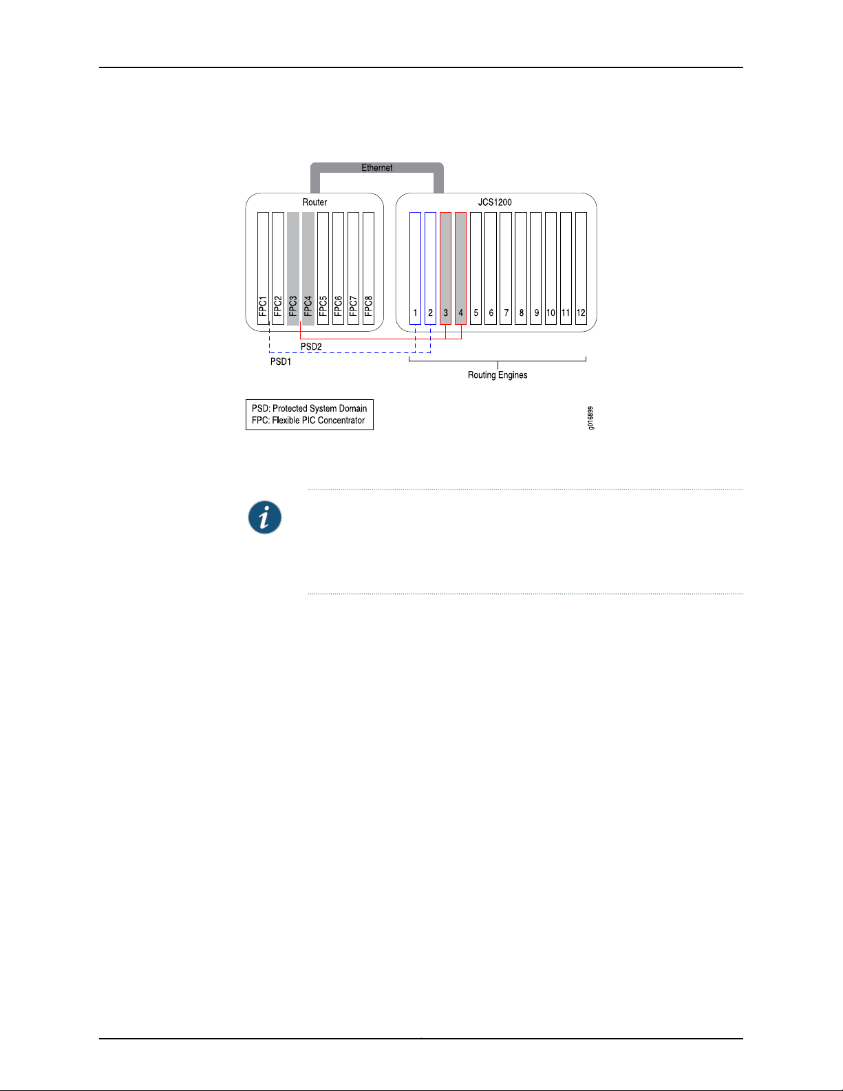
(FPCs) on a T Series router. In Figure 1on page 5, FPC1 and FPC2 and the Routing Engines
in slots 1 and 2 belong to PSD1. In contrast, PSD2 is made up of the FPCs in slots 3 and 4
on the T Series router and the Routing Engines in slots 3 and 4 on the JCS1200 chassis.
Copyright © 2010, Juniper Networks, Inc.4
Page 29
Chapter 1: JCS1200 Chassis and T Series Routers as a Single Platform
Figure 1: Protected System Domain
Any number of FPCs can be assigned to a PSD. Only one redundant Routing Engine pair
(or single Routing Engine) can be assigned to a PSD.
Related
Documentation
NOTE: When an FPC is not assigned to a PSD, it belongs to the Root System
Domain (RSD) by default. A Physical Interface Card (PIC) on an FPC owned
by the RSD can be configured as an interface that is shared by multiple PSDs.
For more information, see “Shared Interfaces” on page 5.
You create each PSD under the RSD configuration through the Junos OS running on the
Routing Engines on the T Series router. Once a PSD is configured, you access it as you
would any separate physical router by connecting to the console port on the master
Routing Engine on the JCS1200 chassis for the PSD you want to configure. Using the
Junos OS, configure basis system properties, such as hostname, domain name, Ethernet
management IP address, and so on. You can also download a configuration file to the
PSD.
A PSD detects and manages only its own Routing Engines in the JCS1200 chassis and
the assigned FPCs and PICs in the T Series router. In addition, failures on one PSD do not
affect other PSDs.
Root System Domains on page 4•
• Shared Interfaces on page 5
• Connections Between JCS1200 and T Series Chassis on page 11
• Benefits of JCS1200 and T Series as a Single Platform on page 13
Shared Interfaces
A single Physical Interface Card (PIC) can host a physical interface that is shared by
different Protected System Domains (PSDs). The Flexible PIC Concentrator (FPC) and
5Copyright © 2010, Juniper Networks, Inc.
Page 30
g016952
Protected System Domain 1
Tunnel PIC
Protected System Domain 2
Root System Domain
OC192
Shared physical interface
Logical interfaces
Cross-connect
Tunnel PIC
logical
interface 1
logical
interface 2
logical
interface 3
JUNOS 10.4 Protected System Domain Configuration Guide
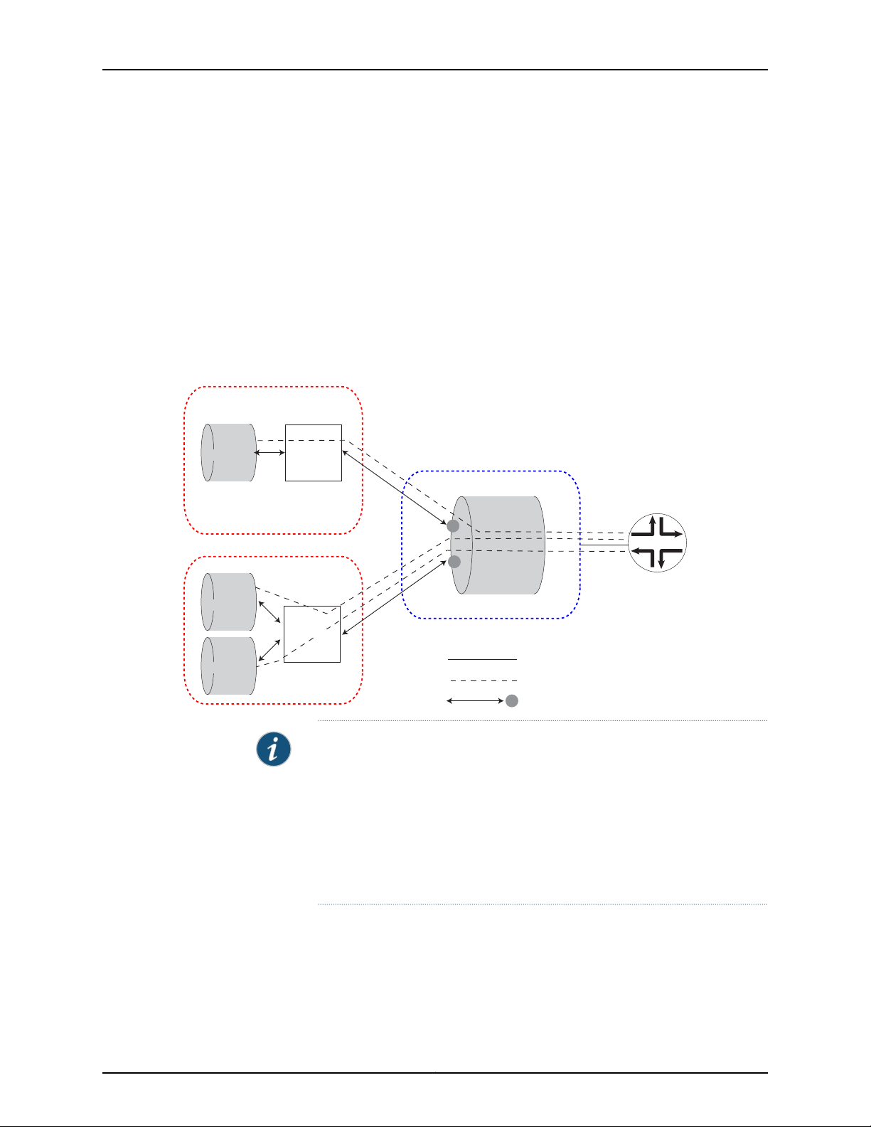
the physical shared interface are owned by the Root System Domain (RSD). However,
the logical interfaces configured under the shared interface are assigned to and owned
by different PSDs. By sharing a single interface among multiple PSDs, the cost of traffic
forwarding is reduced and resources can be allocated flexibly at a more granular level.
Any FPC that has not been assigned to a specific PSD can be used to host shared
interfaces. Onthe RSD, multiple logical interfaces areconfigured on the physical interface
and each individual logical interface is assigned to a different PSD. On the PSD, each
assigned logical interface is configured and peered with an uplink tunnel interface
(ut-fpc/pic/slot), which transports packets between the PSD and the shared interface
on the RSD. See Figure 2 on page 6.
Figure 2: Shared Interfaces
NOTE:
When applied to shared interfaces:
•
Junos features that are configured under logical interfaces, such as
class-of-service(CoS) classifiers and rewrites, firewallfilters, and policers,
are configured on the PSD.
•
Junos features that are configured under physical interfaces, such as drop
profiles and schedule maps, are configured on the RSD.
The packets belonging to a shared interface pass between the Packet Forwarding Engine
on the PIC in the RSD and the Packet Forwarding Engine on the uplink tunnel PIC in the
PSD through a cross-connect in the forwarding fabric.
Copyright © 2010, Juniper Networks, Inc.6
Page 31

Chapter 1: JCS1200 Chassis and T Series Routers as a Single Platform
Traffic flow from the PSD to the RSD over a shared interface is as follows:
1. A packet destined for the shared PIC at the RSD is received on an interface at the PSD
and sent to the Packet Forwarding Engine on the PSD’s tunnel PIC. (The tunnel PIC
is configured to peer with the shared PIC at the RSD.)
2. The packet is sent out of the tunnel interface.
3. The tunnel PIC loops the packetback tothe input side of itsPacket Forwarding Engine
and the packet is sent over the switch fabric to the Packet Forwarding Engine on the
shared PIC at the RSD.
4. The packet is then sent out the shared interface.
Traffic flow from the RSD to the PSD is as follows:
1. The Packet Forwarding Engine on the shared PIC at the RSD determines on which
logical interface the packet arrived.
2. Based on the RSD configuration, the PSD that is associated with this logical interface
is known and the packet is sent over the switch fabric to the tunnel PIC at that PSD.
3. The packet is sent out the tunnel interface.
4. The tunnel PIC loops the packet backto theinput side of its Packet ForwardingEngine
and the packet is then handled as if it had arrived on a directly-connected PIC.
Table 2 on page 7 lists the PICs that support shared interfaces:
Table 2: PICs Supporting Shared Interfaces
First Junos OS
ReleasePIC Model NumberPIC Name
Ethernet
9.4PC-1XGE-DWDM-CBAND1-port 10-Gigabit Ethernet DWDM
9.4PC-1XGE-XENPAK1-port 10-Gigabit XENPAK
9.6PD-4XGE-XFP4-port 10-Gigabit Ethernet LAN/WAN,
XFP
9.4PC-10GE-SFP10-port 1-Gigabit SFP
SONET/SDH
9.3PC-4OC48-SON-SFP4-port OC48 SONET, SFP
9.3PC-10C192-SON-SFP1-port OC192 SONET, XFP
9.3PD-4OC192-SON-XFP4-port OC192 SONET, XFP
9.3PD-1OC768-SON-SR1-port OC768 SONET, SR
7Copyright © 2010, Juniper Networks, Inc.
Page 32

JUNOS 10.4 Protected System Domain Configuration Guide
NOTE: Only SONET PICs that are installed on an Enhanced Services (ES)
FPC on a T320 router or on a T1600 router can support shared interfaces.
Related
Documentation
JCS1200 Chassis and T Series Core Routers as a Single Platform on page 3•
• Root System Domains on page 4
• Protected System Domains on page 4
• Connections Between JCS1200 and T Series Chassis on page 11
• Benefits of JCS1200 and T Series as a Single Platform on page 13
Inter-PSD Forwarding Overview
Inter-PSD forwarding enables PSDs on the JCS1200 platform to communicate on a
peer-to-peer basis without requiring external links. Previously, PSDs could communicate
with each other only through an external link.
Inter-PSD forwarding is achieved by using tunnel PICs that reside on the PSD. Each PSD
you configure for inter-PSD forwarding must have a tunnel PIC available to the PSD. The
PSDs communicate over logical interfaces configured on the tunnel PICs. Multiple logical
interfaces can be configured on each tunnel PIC, allowing the PSD to communicate with
multiple PSDs over the same tunnel PIC.
Currently, only Frame Relay encapsulation is supported for inter-PSD forwarding.
Related
Documentation
Root System Domains on page 4•
• Protected System Domains on page 4
Route Reflection Overview
To decrease BGP control traffic and minimize the number of update messages, a BGP
route reflector is used in many networks to distribute BGP routes within the AS. Routing
Engines on the JCS1200 platform can be configured to act as BGP route reflectors.
Because of largememory and64-bit processor capacity,JCS1200 Routing Engines provide
ideal support for route reflection.
Typically, route reflection is performed by a dedicated router. The router is not in the
forwarding path (does not forward IP packets) but is equipped with a large memory and
a good CPU.
The number of route reflectors in an IP network is much smaller than the number of
routers. A network with 30 or more routers might have one route reflector (or possibly
two for redundancy). Larger networks with hundreds of routers, might have 20 router
reflectors.
Figure 3 on page 9 shows a typical network with route reflectors. These route reflectors
are not in the forwarding path.
Copyright © 2010, Juniper Networks, Inc.8
Page 33

RR 1
RR 2
RR 3
RR 4
PE
PE
PE
PE
PE
g017292
g017293
PE
PE
PE
PE
PE
RR1
RR2
RR3
RR4
Chapter 1: JCS1200 Chassis and T Series Routers as a Single Platform
Figure 3: Typical Network of Route Reflectors
Figure 4 on page 9 shows the JCS1200 platform providing four distinct route reflectors
and preserving the current network architecture.
Figure 4: Route Reflectors on the JCS1200 Platform
Figure 5 on page 10 shows an example of route reflector partitioning on the JCS1200
platform. Each JCS1200 chassis can hold up to 12 Routing Engines. You can get route
scalability up to 12x as you incrementally add Routing Engines to the JCS1200 chassis
and configure them for route reflection. You do not need to buy a new router to increase
route reflector capacity.
9Copyright © 2010, Juniper Networks, Inc.
Page 34

RR2 RR3 RR4 RR5 RR5 RR6 RR6RR1
M B M B
JCS1200 Platform
RR1 RR2 RR2 RR3 RR3 RR4 RR4RR1
M B M BM B M B
JCS1200 Platform
POP1
POP2
PE PE
VPN 301-400
VPN 201-300VPN 101-200
VPN 1-100
g017294
JUNOS 10.4 Protected System Domain Configuration Guide
Figure 5: Route Reflector Partitioning on the JCS1200 Platform
NOTE: Support for dual Routing Engines (master and backup) is currently
not available, but is planned for a future release.
As shown in Figure 6 on page 11, each of the 12 Routing Engines can be configured as a
standalone route reflector. The 12 RoutingEngines on the JCS1200 platform are connected
to the JCS switch modules in a dual-star configuration. Each Routing Engine has access
to two interfaces (fxp0 and fxp1), one on each switch. These interfaces are used for
protocol peerings.
Each JCS switch module has 6 Gigabit Ethernet ports to connect to the outside world
for a total of 12 ports. One port on each JCS switch module is used as a management
port, three of the remaining ports on each JCS switch module can be used to connect to
the network. (The remainingtwo ports are reserved.) Each GigabitEthernet port represents
a separate LAN.
Multiple route reflectors can be configured to share the same port and hence be part of
the sameLAN. Portsharing enables JCS1200route reflectorsto conserve Gigabit Ethernet
ports and reduce the cost of adding additional line cards for connectivity to the network.
The result is a cost-effective solution for networks where multiple route reflectors are
deployed.
Copyright © 2010, Juniper Networks, Inc.10
Page 35

JCS1200 Platform
Internal LAN
RE1
RE2
RE3
RE4
RE5
RE6
RE7
RE8
RE9
RE10
RE11
RE12
RR1
RR2
RR3
RR4
g017295
Switch Module 1
Switch Module 2
fxp0
fxp1
Six GE ports
Six GE ports
Chapter 1: JCS1200 Chassis and T Series Routers as a Single Platform
Figure 6: Route Reflector Interfaces and Ports
Related
Documentation
Root System Domains on page 4•
• Protected System Domains on page 4
• Example: Configuring the JCS1200 Platform as a Route Reflector on page 157
• Example: Configuring Client-to-Client Reflection (OSPF) on page 166
Connections Between JCS1200 and T Series Chassis
The JCS1200 and T Series routers areconnectedthrough standard Ethernet linksbetween
one or more JCS switch modules and one or more T Series Control Boards (T-CBs). The
JCS switch module has six ports. Port 1 is connected to Root System Domain 1 (RSD1),
port 2 to RSD2, and port 3 to RSD3. Port 6 connects to the management ports on all
Routing Engines in the JCS chassis. Port 4 and port 5 are reserved.
In Figure 7 on page 12, Ethernet port 1 (RSD1) on JCS switch module 1 is connected to the
T SeriesConnector Interface Panel (CIP) port on T-CB-0,whereas Ethernet port 1(RSD1)
on JCS switch module 2 is connected to the CIP port on T-CB-1.
When there are two JCS switch modules, each Routing Engine can be configured with
two Ethernet management ports. One port (fxp0.0) is connected to port 6 on the JCS
switch module in bay 1, whereas the other port (fxp1.0) is connected to port 6 on the JCS
switch module in bay 2. Each connection is a dedicated 1000-Mbps link.
11Copyright © 2010, Juniper Networks, Inc.
Page 36

JUNOS 10.4 Protected System Domain Configuration Guide
Figure 7: JCS Switch Module Ports
When you firstaccessa PSDthrough theconsole port on theRouting Engine, youconfigure
the IP address for one or both of these management ports.
Figure 8 on page 12 provides a more detailed look at the connections between the two
platforms. RE m indicates a master Routing Engine on the JCS1200 platform, whereas
RE b represents a backup Routing Engine.
Figure 8: Connections Between JCS1200 and T Series Platforms
Copyright © 2010, Juniper Networks, Inc.12
Page 37

Chapter 1: JCS1200 Chassis and T Series Routers as a Single Platform
Related
Documentation
Configuring a PSD with a Single Routing Engine on page 87•
• Configuring a PSD with Redundant Routing Engines on page 89
• Connecting the JCS1200 Platform to a T Series Core Router
Benefits of JCS1200 and T Series as a Single Platform
The benefits of the JCS1200 and T Series routers as a single platform are:
•
Increased efficiency and investment protection—A single T Series router used with the
JCS1200 platform supports up to eight Protected System Domains (PSDs). With
multiple (up to 3) T Series chassis connected to the JCS1200 chassis, 12 PSDs can be
supported. Instead of purchasing 12 physical routers, a service provider can configure
12 PSDs using a single interconnected platform. In addition, operations and
administration are simplified through consolidation of resources.
•
Maximum scaling and flexibility—A highly scalable control plane chassis preserves
slots in the router chassis that can be used for revenue-generating, high-speed
forwarding of Internet traffic. Service providers can assign control processors and
memory space on the Routing Engines in the JCS chassis to achieve the most efficient
use of resources, while deliveringoutstanding performance. In addition, different PSDs
can share interfaces on a single Physical Interface Card (PIC), reducing capital
expenditure and enabling you to allocate resources with finer granularity.
•
Rapid service rollout—Newservices can be planned, tested, and deployed more quickly
with fewer resources. Each PSD provides a secure administration domain, where new
features can be tested, while other PSDs continue to provide tested software to
customers. Through fault isolation and streamlined administration domains, service
providersachieve faster revenue andaccommodaterapid customer growth. In addition,
RSDs and PSDs can run different version of Junos OS; however, the supported Junos
OS Release version must be one release up, or one release down, from the current
Junos OS Release version. For example, if RSD is running Junos OS Release 10.1, then
PSD can run Junos OS Release 10.0 or 10.2, however, it cannot run Junos OS Release
9.6 or 10.3. Each RSD and PSD must be running Junos Release 9.4 or later.
The following sections discuss some of these benefits:
•
Network Consolidation on page 13
•
Enhanced Security and Administration on page 14
•
Cost Efficiency on page 15
•
Faster Deployment of New Services on page 15
Network Consolidation
Many carriers operate separate IP networks for public and private services. Others have
application-specific IP networks (voice and video, for example). PSDs enable carriers to
consolidate and simplify network architecture. Rather than adding more routing at the
edge to support individual services, a single platformprovides service-specific virtualization
in the core of the network.
13Copyright © 2010, Juniper Networks, Inc.
Page 38

JUNOS 10.4 Protected System Domain Configuration Guide
In Figure 9 on page 14, three separate networks (IPTV, enterprise VPN, and public IP) are
consolidated into one network. Instead of three core routers, only the JCS 1200 platform
interconnected with a single T640 router is required to support all three services.
Figure 9: Network Consolidation
Enhanced Security and Administration
By delineating fault and administrative domains on a singlesystem,PSDs enable network
administrators to decrease the number of nodes and fiber interconnections between
routers,reducing thecost andcomplexityof existingpoint of presence (PoP) architectures.
Because each PSDmaintains itsown routingand processes inseparatepartitions, security
is enhanced. With fault isolation, network anomalies in one PSD do not affect another
PSD.Streamlined boundaries allowoperational domains to be isolated logically, providing
more control over router administration.
Copyright © 2010, Juniper Networks, Inc.14
Page 39

Chapter 1: JCS1200 Chassis and T Series Routers as a Single Platform
Cost Efficiency
With PSDs, forwarding resources are allocated to where they are most needed. This
flexibility ensures that the most bandwidth-intensive services receive the resources
needed to guarantee service license agreements. By consolidating network equipment
and functions and streamlining management and administrative tasks, the utilization of
resources is maximized. Shared interfaces enable you to assign expensive forwarding
resources with more granularity to specific routing domains. RSDs and PSDs can run
different versions of Junos OS; howeve, the supported Junos OS Release version must
be one release up, or one release down, from the current Junos OS Release version. For
example, if RSD is running Junos OS Release 10.1, then PSD can run Junos Release 10.0
or 10.2;however, it cannot runJunos OS Release9.6 or 10.3. Toconfigure shared interfaces,
each RSD and PSD must be running Junos OS Release 9.3 or later.
Faster Deployment of New Services
Service providers can use a separate partition for testing and activating new services
without having to deploy a new system. Software upgrades can occur without affecting
software versions used for existing services. Carriers can begin generating revenue more
quickly and minimize the cost of introducing new services.RSDs andPSDs canrun different
versions of Junos OS; however, the supported Junos OS Release version must be one
release up, or one release down, from the current Junos OS Release version. For example,
if RSD is running Junos OS Release 10.1, then PSD can run Junos OS Release 10.0 or 10.2;
however, it cannot run Junos OS Release 9.6 or 10.3. Each RSD and PSD must be running
Junos Release 9.4 or later.
Related
Documentation
• Example: Configuring a JCS1200 Platform and a Single T Series Router on page 123
• Example: Configuring a JCS1200 Platform and Multiple T Series Routers on page 128
• Example: Configuring Shared Interfaces (Ethernet) on page 147
• Example: Consolidating a Layer 2 VPN Network on page 177
15Copyright © 2010, Juniper Networks, Inc.
Page 40

JUNOS 10.4 Protected System Domain Configuration Guide
Copyright © 2010, Juniper Networks, Inc.16
Page 41

CHAPTER 2
JCS1200 and T Series Platform Software
Views
•
Software Views Overview on page 17
•
JCS Administration View on page 17
•
RSD Administration View on page 18
•
PSD Administration View on page 19
Software Views Overview
Configuring and managing the Juniper Networks JCS1200 control system and connected
T Series routers requires three separate control points (views). Each view provides a
different access to different parts of the system:
•
Through the JCS management module command-line interface (CLI), a JCS
administration view enables you to configure and manage JCS1200 platform
components, including the JCS switch module and blade (or Routing Engine)
parameters.
•
Through the Junos OS running on the Routing Engine pair in the T Series router (called
the Root System Domain), the RSD administration view enables you to create the
Protected System Domains (PSDs) and to manage all the hardware in the T Series
chassis.
•
Through the Junos OS running on a Routing Engine (or Routing Engine pair) in the JCS
chassis, the PSD administration view enables you to configure and manage the hardware
that is assigned to the PSD.
Related
Documentation
JCS Administration View on page 17•
• RSD Administration View on page 18
• PSD Administration View on page 19
JCS Administration View
The JCS administration view is controlled by JCS supervisors and operators who have
access to configuration and settings associated with the hardware and software that
17Copyright © 2010, Juniper Networks, Inc.
Page 42

JUNOS 10.4 Protected System Domain Configuration Guide
reside on the JCS1200 platform. This includes JCS management modules, JCS switch
modules, the JCS Routing Engines (blades), JCS media trays, power supplies, and so on.
JCS administration view considerations include:
•
Types of JCS Users on page 18
•
How Command Targets and User Permissions Impact Views on page 18
Types of JCS Users
Users are authenticated by the JCS management module before they can issue JCS
commands. Login account configuration determines which commands are available.
Two types of Juniper Networks-specific login accounts are available on the JCS:
•
Supervisor—Login accounts configured with supervisor privileges enable you to view
and enter JCS management module configuration commands such as users and write.
You can also view and enter JCS management module monitoring commands.
•
Operator—Login accounts configured with operator privileges enable you to view and
enter JCS management module operational commands such as info and health. JCS
management module configuration commands are not available for operator logins
How Command Targets and User Permissions Impact Views
Views available to JCS users are based on a combination of user login permissions and
the target set for a command. For example:
•
You can set thecommand target of the info command to selectivelydisplay information
about a specific Routing Engine in the JCS chassis, all Routing Engines in the chassis,
and so on.
•
JCS operators can use the ifconf command to display network interface settings for
the JCS Ethernet interfaces. In addition, JCS supervisors can use the ifconf command
to change network interface settings.
Related
Documentation
RSD Administration View on page 18•
• PSD Administration View on page 19
• JCS1200 Software Components on page 23
• Configuring User Accounts on page 42
RSD Administration View
The Root System Domain (RSD) view is controlled by the administrators and users of
the Junos OS running on the Routing Engines on the T Series router. RSD administration
view considerations include:
•
Access Privileges on page 19
•
System Information on page 19
•
Management Tasks on page 19
Copyright © 2010, Juniper Networks, Inc.18
Page 43

Access Privileges
System Information
Chapter 2: JCS1200 and T Series Platform Software Views
The RSD administrator creates the PSDs through the Junos OS running on the Routing
Engines in the T Series chassis. With the correct user privileges and authentication, an
RSD administrator can log in to a PSD from the RSD.
The RSD administrator can use the show chassis psd command to view which PSDs are
configured within the RSD. Otherwise, when issuing show commands on the RSD, the
administrator views all hardware on the T Series router.
By default, system log files are stored in the /var/log/message directory on the router. If
a system log message on an RSD originates from an FPC that is assigned to a PSD, the
system message is logged locally at the RSD and is also forwarded to that particular
PSD.If a system log message originates from ahardware resource that is shared between
and RSD and PSDs, the message is logged locally at the RSD and is also forwarded to
all PSDs associated with the RSD.
Management Tasks
The RSD administrator manages all hardwareon the T Series router, including the Routing
Engines, FPCs, Switch Interface Boards (SIBs), the Switch Processor Mezzanine Board
(SPMB), Power Entry Modules (PEMs), and fans. The RSD administrator can issue show,
request, clear, and test commands for any hardware on the T Series router and for any
FPCs that are part of a PSD.
Related
Documentation
JCS Administration View on page 17•
• PSD Administration View on page 19
• Logging In to a PSD from the RSD on page 237
• Junos OS Verification Tasks on page 238
PSD Administration View
The Protected System Domain (PSD) view is controlled by the administrators and users
of the Junos OS running on the Routing Engines in the JCS chassis that belong to a
particular PSD. Topics in this section include:
NOTE: A switchover between Routing Engines on the T Series router (the
RSD) does not affect PSDs. However, when an RSD reboots or goes offline,
the FPCs assigned to PSDs will reboot or go offline.
•
Access Privileges on page 20
•
System Information on page 20
•
Management Tasks on page 20
19Copyright © 2010, Juniper Networks, Inc.
Page 44

JUNOS 10.4 Protected System Domain Configuration Guide
Access Privileges
Each PSD is independent of all other PSDs and requires login authentication. When you
initially configure a PSD, you set its root authentication parameters. Authentication is
enforced when a user attempts to log in to a PSD directly or from the RSD.
System Information
The PSD administrator can display information about the Routing Engines, FPCs, and
PICs that are assigned to the PSD. The administrator can also display information about
shared T Series hardware, such as SIBs, the SPMB, PEMs, and fans. When a show
command is issued on a PSD, a field heading such as psd1-re0: precedes the set of
information that pertains only to the PSD, whereas a field heading such as rsd-re0:
precedes the set of information that pertains to the shared hardware.
Systemlog messages originating from an FPC that is assigned to aPSD are logged locally
at the RSD and forwarded to the PSD. Ifa system log message originates froma hardware
resource that is shared between and RSD and PSDs, the message is logged locally at
the RSD and is forwarded to all PSDs associated with the RSD. Again, you can determine
the origin of a system message by labels such as psd1-re0: and rsd-re0:.
Management Tasks
Related
Documentation
The PSD administrator controls and manages Routing Engines and FPCs assigned to
that PSD. Forexample, the PSD administrator can issue request, clear, andtest commands
for the FPCs and PICs that are part of the PSD. The PSD administrator has view-only
access to shared T Series hardware, such as SIBs, the SPMB, PEMs, and fans.
NOTE: A switchover between Routing Engines on the JCS1200 platform that
are assigned to a PSD does not affect the RSD or other PSDs. However, when
the masterRouting Engine in a PSD reboots or goes offline, the FPCs assigned
to that particular PSD will reboot or go offline.
• JCS Administration View on page 17
• RSD Administration View on page 18
• Logging In to a PSD from the RSD on page 237
• Junos OS Verification Tasks on page 238
Copyright © 2010, Juniper Networks, Inc.20
Page 45

CHAPTER 3
JCS1200 Platform Components
•
JCS1200 Platform Hardware Components on page 21
•
JCS1200 Software Components on page 23
•
JCS1200 Platform Graceful Routing Engine (GRES) Switchover on page 27
JCS1200 Platform Hardware Components
JCS1200 platform hardware components include:
•
Default Hardware Configuration on page 21
•
Routing Engines on page 21
•
Management Module on page 22
•
Switch Module on page 22
•
Media Tray on page 22
•
Power Supply Modules on page 22
•
Fan Modules on page 23
Default Hardware Configuration
The default configuration for the JCS1200 platform includes:
•
One JCS management module
•
One JCS switch module
•
Four power supplies
•
One media tray
Routing Engines
The JCS chassis provides 12 slots (bays) for Routing Engines. A Routing Engine is a
hot-swappable, independent server with its own processors, memory, storage, network
controllers, operating system, and applications. The Routing Engine is installed in a slot
in theJCS chassis andshares power, fans, switches, and ports with otherRouting Engines.
Routing Engines in the JCS1200 platform have the latest Junos OS preinstalled on them.
21Copyright © 2010, Juniper Networks, Inc.
Page 46

JUNOS 10.4 Protected System Domain Configuration Guide
Management Module
The JCS management module is a hot-swappable module that you use to configure and
manageJCS components. TheJCS chassiscomes withone hot-swappablemanagement
module in management module slot 1. To provide redundancy, you can add a second
management module in management module slot 2. Only one management module is
active. The other is a backup in case of failure. Each JCS management module has a
separate internal link to each JCS switch module. See Figure 10 on page 22.
Figure 10: JCS Management Module
You can access theJCS management module CLI through a local connectionto the serial
port on the JCS management module. Or, you can access the CLI from a remote network
management station on the network through the console (Ethernet) connector.
Switch Module
Media Tray
Power Supply Modules
The JCS switch module connects Routing Engines on the JCS1200 platform to a T Series
router and controls traffic between the two devices. The JCS chassis comes with one
hot-swappable switch module in switch module slot 1. To provide redundancy, you can
add a second switch module in switch module slot 2.
The media tray is a hot-swappable module that provides two USB connectors for use
by the Routing Engines, error LEDs, an ambient air temperature sensor and a pressure
sensor for use by the JCSmanagement module, and two CompactFlash card slots. Junos
OS is preloaded onto each Routing Engine. The media tray USB ports are used to copy
new Junos OS packages onto Routing Engines. See Figure 11 on page 22. The JCS chassis
comes with one hot-swappable media tray in media tray slot 1. To provide redundancy,
you can add a second media tray in media tray slot 2.
Figure 11: JCS Media Tray
The JCS chassis is configured withfour hot-swappable power supplymodules. The power
supply modules in slots 1 and 2 supply power to Routing Engine slots 1 through 6, media
trays 1 and 2, management module slots 1 and 2, and switch module slots 1 and 2. Power
supply modules in slots 3 and 4 supply power to Routing Engine slots 7 through 12.
Copyright © 2010, Juniper Networks, Inc.22
Page 47

Fan Modules
Chapter 3: JCS1200 Platform Components
Each pair of power modules operates as a redundant pair. If either power module fails,
the remaining power module continues to supply power, but there is no redundancy.
Replace a failed power module as soon as possible.
The JCS1200 platform comes with four hot-swappable fan modules for cooling
redundancy. The fan module speeds vary depending on the ambient air temperature
within the JCS1200 platform.
If the ambient temperature is 25°C (77°F) or below, the JCS1200 platform fan modules
will run at their minimum rotational speed. If the ambient temperature is above 25°C
(77°F), the fan modules will run faster, increasing their speed as required to control
internal JCS1200 platform temperature.
Each fan module contains two fans operating as a pair in a series. If one fan fails, the
remaining fan will runat fullspeed and continue tocool theJCS1200 platform. To maintain
cooling redundancy, replace a failed fan module as soon as possible.
Related
JCS1200 Software Components on page 23•
Documentation
JCS1200 Software Components
The JCS1200 software includes the following concepts and components:
•
JCS Management Module CLI Overview on page 23
•
Logging In to the JCS Management Module CLI on page 24
•
Getting Help on JCS Commands on page 24
•
Setting the JCS Management Module Command Target on page 25
•
JCS Switch Module Script on page 26
JCS Management Module CLI Overview
The JCS management module command-line interface (CLI) is the software interface
you use to access and configure the Juniper Networks Control System (JCS). You can
access the JCS management module CLI through a local connection to the serial port
on the JCS management module. Or, you can access the CLI from a remote network
management station on the network through the console (Ethernet) connector.
The JCS management module CLI is a straightforward command interface. You type
commands on a single line, and commands are executed when you press the Enter key.
The CLI provides command help and command history.
Unlike the Junos OS CLI, in which configuration commands you enter are stored in a
candidate configuration and the changes you add are not activated until you commit the
configuration, configuration commands you enter with the JCS management module
CLI are activated as soon as you enter the command.
General information about JCS CLI commands includes:
23Copyright © 2010, Juniper Networks, Inc.
Page 48

JUNOS 10.4 Protected System Domain Configuration Guide
•
All JCS CLI commands have the following basic structure:
command -option parameter
An option is a single-letter code or word that refines the behavior of a command in
some predetermined way. A parameter, also known as a command-line argument, is
a filename or other data that is provided to a command. Some commands do not
require options, and some commands do not require parameters.
•
All commands, command options, and predefined parameters are case-sensitive.
•
Command options are indicated by a dash (-).
•
Strings that contain spaces are enclosed in quotation marks. For example:
snmp -cn “John Markham”
•
Depending on which command options you enter, you can use the same JCS CLI
command to display configuration information or to change a configuration. For
example, compare the following:
mt -T system
Displays the Routing Engine (blade) that currently controls (owns) the media tray.
mt -T system –b 6
Configures the Routing Engine (blade) in slot 6 to control the media tray.
Logging In to the JCS Management Module CLI
To log in to the JCS management module for the first time, use the default username
and password:
Username: USERID
Password: PASSW0RD
The 0 in PASSW0RD is a zero, not the letter O.
When you have created user accounts, you can log in as a specific user.
Getting Help on JCS Commands
The JCS management module CLI includes a help command you can use to get a list of
available commands or to get help on individual commands.
•
For a list of available commands, enter the help command. For example:
system> help
? – Display commands
accseccfg — View/edit account security config
advfailover — View/edit advanced failover mode
alarm — Manage Telco System Management alarm(s)
alertcfg — Displays/Configures the global remote alert systems
alertentries — View/edit remote alarm recipients
baydata — View/edit Blade Bay Data string
...
•
For help on individual commands, enter command -help, where command is the name
of the command for which you want help. For example:
Copyright © 2010, Juniper Networks, Inc.24
Page 49

Chapter 3: JCS1200 Platform Components
system> clock -help
usage:
clock [-options]
options:
-d - date (mm/dd/yyyy)
-t - time (hh:mm:ss)
-g - GMT offset
-dst - daylight savings time (on|off|special case)
For a GMT offset of +2:00, use one of the following values for dst:
ee - Eastern Europe
gtb - Great Britain
egt - Egypt
fle - Finland
off
For a GMT offset of +10:00, use one of the following values for dst:
ea - Eastern Australia
tas - Tasmania
vlad - Vladivostok
off
For a GMT offset in set {-9:00, -8:00, -7:00, -6:00, -5:00}, use one of
the
following values for dst:
uc - USA and Canada
other - Other locations
off
For a GMT offset of -4:00, use one of the following values for dst:
can - Canada
other - Other locations
off
•
You can also use the ? or -h shortcuts to get help. For example:
system> clock -h
system> clock ?
Table 3 on page 25 shows syntax conventions used in help command output.
Table 3: Syntax Conventions for JCS Management Module CLI Help
Setting the JCS Management Module Command Target
You can use the JCS management module CLI to direct commands to the management
module or other devices installed in the JCS chassis. The device where the command
takes effect is called the command target. By default, the command target is system
(the JCS chassis).
DescriptionItem
Used for indexing (by slot (bay) number)[ ]
Denotes a variable< >
Denotes an optional argument{ }
Denotes a choice|
25Copyright © 2010, Juniper Networks, Inc.
Page 50

JUNOS 10.4 Protected System Domain Configuration Guide
•
Use the env command to change the command target. For example:
•
The following command changes the command target from system to JCS
management module 1 (mm[1]):
system> env -T mm[1]
OK
system:mm[1]>
The command prompt changes to system:mm[1] to indicate the command target.
Unless otherwise directed, all commands you enter apply to the target shown by
the prompt.
•
To return the command target to the top level of the hierarchy, type the following:
system:mm[1]: env -T system
OK
system>
•
Use the -T option to temporarily override the active command target for individual
commands. For example, to include the following command option to redirect a
command to the JCS management module in slot (bay 1), type:
-T system:mm[1]
Table 4 on page 26 lists command targets you typically use to configure and monitor the
JCS1200 platform.
Table 4: Target Paths for JCS Modules
system:mm[x]JCS management module
NOTE: Additional target paths are available in the JCS management module
CLI.
JCS Switch Module Script
DescriptionTarget PathItem
–systemJCS1200 platform
x is the management module number (1
or 2)
x is the blade slot number (1 through 12)system:blade[x]Routing Engine (blade server)
x is the switch number (1 or 2)system:switch[x]JCS switch module
The JCS switch module includes a menu-based interface that runs on the JCS1200
platform. However, instead of using menus to configure the switch, Juniper Networks
provides a script you can use for configuring the switch.
Copyright © 2010, Juniper Networks, Inc.26
Page 51

Chapter 3: JCS1200 Platform Components
Related
JCS1200 Platform Hardware Components on page 21•
Documentation
JCS1200 Platform Graceful Routing Engine (GRES) Switchover
•
Graceful Routing Engine Switchover Overview on page 27
•
Graceful Routing Engine Switchover PIC Support on page 27
Graceful Routing Engine Switchover Overview
The Graceful Routing Engineswitchover(GRES) featurein theJunos OS enables a routing
platform with redundant Routing Engines to continue forwarding packets even if one
Routing Engine fails. GRES preserves interface and kernel information. Traffic is not
interrupted. For more information, on GRES, see the Junos High Availability Configuration
Guide.
•
To configureGRES onthe JCS1200platform,include thegraceful-switchover statement
at the [edit chassis redundancy routing-engine] hierarchy level on the PSD.
•
Configure the graceful-switchover statement for all PSDs on the JCS1200 platform
that include redundant Routing Engines.
Graceful Routing Engine Switchover PIC Support
Junos OS Release10.0 or higher supports GRES for PICsrunning onthe JCS1200 platform,
including IQ2PICs. IQ2 PICs supported on the JCS1200 platforminclude 1-, 4-, and 8-port
Gigabit Ethernet IQ2 PICs and 1-port 10-Gigabit Ethernet IQ2 PICs.
Related
Documentation
• Junos High Availability Configuration Guide
• Configuring a PSD with Redundant Routing Engines on page 89
27Copyright © 2010, Juniper Networks, Inc.
Page 52

JUNOS 10.4 Protected System Domain Configuration Guide
Copyright © 2010, Juniper Networks, Inc.28
Page 53

PART 2
Configuration Overview
•
Before You Begin on page 31
•
Configuration Roadmap on page 33
29Copyright © 2010, Juniper Networks, Inc.
Page 54

JUNOS 10.4 Protected System Domain Configuration Guide
Copyright © 2010, Juniper Networks, Inc.30
Page 55

CHAPTER 4
Before You Begin
•
Verifying the FPC BootROM Version on page 31
•
Keeping the JCS Management Module Default SNMP Setting on page 32
Verifying the FPC BootROM Version
Before connecting the JCS1200 platform to any T Series router, ensure that the bootROM
version for all FPCs on the T Series chassis is ROM Monitor Version 6.4 or later. If an FPC
bootROM version is earlier than Version 6.4, the FPC will not come online. To upgrade
the firmware, you must contact your Juniper Networks customer support representative.
To determineif youneed to upgrade the FPC firmware, display the version of the firmware
on all FPCs by issuing the show chassis firmware command:
user@host> show chassis firmware
Part Type Version
FPC 0 ROM Juniper ROM Monitor Version 7.5b4
O/S Version 9.1-20080222.0 by builder on 2008-0
FPC 1 ROM Juniper ROM Monitor Version 6.4b18
O/S Version 9.1-20080222.0 by builder on 2008-0
FPC 2 ROM Juniper ROM Monitor Version 7.5b4
O/S Version 9.1-20080222.0 by builder on 2008-0
FPC 4 ROM Juniper ROM Monitor Version 6.4b18
O/S Version 9.1-20080222.0 by builder on 2008-0
FPC 5 ROM Juniper ROM Monitor Version 6.4b20
O/S Version 9.1-20080222.0 by builder on 2008-0
FPC 6 ROM Juniper ROM Monitor Version 7.5b4
O/S Version 9.1-20080222.0 by builder on 2008-0
FPC 7 ROM Juniper ROM Monitor Version 6.4b20
O/S Version 9.1-20080222.0 by builder on 2008-0
SPMB 0 ROM Juniper ROM Monitor Version 6.4b18
O/S Version 9.1-20080222.0 by builder on 2008-0
SPMB 1 ROM Juniper ROM Monitor Version 6.4b18
O/S Version 9.1-20080222.0 by builder on 2008-0
Related
Documentation
Keeping the JCS Management Module Default SNMP Setting on page 32•
• Configuration Roadmap on page 33
31Copyright © 2010, Juniper Networks, Inc.
Page 56

JUNOS 10.4 Protected System Domain Configuration Guide
Keeping the JCS Management Module Default SNMP Setting
CAUTION: By default, SNMP is enabled on the JCS management module.
Do not disable SNMP. If you disable SNMP, your system might not function
correctly. Also, do not erase or change the SNMP default c1 community.
Related
Documentation
• Verifying the FPC BootROM Version on page 31
• Configuring SNMP Traps on page 43
• Configuration Roadmap on page 33
Copyright © 2010, Juniper Networks, Inc.32
Page 57

CHAPTER 5
Configuration Roadmap
•
Configuration Roadmap on page 33
Configuration Roadmap
Complete the following tasks to configure the JCS1200 platform and T Series routers:
•
Step One: Configure the JCS1200 Platform on page 33
•
Step Two: Configure the T Series Router on page 34
•
Step Three: Configure Basic System Properties on a New PSD on page 34
•
Step Four: Configure Shared Interfaces (Optional) on page 35
Step One: Configure the JCS1200 Platform
To configure theJCS1200 platform, log into the JCSmanagement module command-line
interface (CLI) and:
1. Configure basic system parameters:
•
Restore the default configuration on the JCS management module.
•
Configure the JCS management module Ethernet management interface.
•
Configure the JCS switch module Ethernet management interface.
•
Create user accounts.
•
Configure the NTP server.
•
Configure the time zone.
•
Configure the system name and contact information.
•
Configure Secure Shell (SSH) access.
•
Configure Simple Network Management Protocol (SNMP) traps.
•
Configure the JCS switch module.
2. Configure the Routing Engines (blades) on the JCS1200 platform:
33Copyright © 2010, Juniper Networks, Inc.
Page 58

JUNOS 10.4 Protected System Domain Configuration Guide
•
Configure Routing Engine (blade) bay data to assign a single Routing Engine (or
redundant pair)to a Root System Domain (RSD) and to a unique Protected System
Domain (PSD).
•
Configure Routing Engine (blade) names.
Step Two: Configure the T Series Router
Log in to the master Routing Engineon the T Series router toconfigure it as a Root System
Domain (RSD) andto create ProtectedSystemDomains (PSDs) under the RSD. Through
the Junos OS CLI or through the J-Web user interface:
1. Assign an ID number to the RSD.
This ID number must match the ID number set through the JCS management module
baydata command.
2. Configure a PSD and assign it an ID number.
3. Provide a description of the PSD.
4. Assign one or more FPCs to the PSD.
NOTE: Any FPC that is not assigned to a PSD belongs to the RSD. For
information about how to configure shared interfaces on a SONET PIC in
an unassigned FPC, see “Step Four: Configure Shared Interfaces
(Optional)” on page 35.
5. Assign an ID number to the JCS1200 platform.
The ID number must match the ID number set through the JCS management module
baydata command.
6. Assign a Routing Engine (or redundant pair) on the JCS1200 platform to the PSD.
Routing Engine assignments must match the assignments configured through the
JCS management module baydata command.
7. Repeat Step 2 through Step 6 for each PSD to be configured under the RSD.
8. Repeat this entire procedure for each RSD.
Step Three: Configure Basic System Properties on a New PSD
To configure a PSD, connect to the console port on the Routing Engine on the JCS1200
platform for the PSD you want to configure and, using the Junos OS CLI, include the
following information:
•
Hostname
•
Domain name
•
Ethernet management IP addresses
•
IP address of a backup router
Copyright © 2010, Juniper Networks, Inc.34
Page 59

•
IP address of one or more DNS name servers on your network
•
Password for the root account
Step Four: Configure Shared Interfaces (Optional)
Optionally, configure shared interfaces. Shared interfaces are configured on both the
Root System Domain (RSD) and the Protected System Domain (PSD).
On the Root System Domain (RSD):
1. Configure the physical interface.
2. For SONET interfaces, configure Frame Relay encapsulation. For Ethernet interfaces,
configure virtual LAN (VLAN) tagging.
3. Configure logical interfaces under the physical interface.
4. For each logical interface:
a. Provide anidentifier. For a SONETlogical interface, configure adata-link connection
identifier (DLCI). For an Ethernet logical interface, configure a virtual LAN (VLAN)
identifier.
Chapter 5: Configuration Roadmap
b. Specify the Protected System Domain (PSD) that owns the shared interface.
On the Protected System Domain (PSD):
1. Configure the physical interface (as specified in the RSD configuration).
2. For a SONET interface, configure FrameRelay encapsulation on the physical interface
to match the RSD configuration. For an Ethernet interface, configure VLAN tagging
to match the RSD configuration.
3. For a SONET physical interface, configure the maximum transmission unit (MTU) size
to match the RSD configuration. (If the RSD has no MTU size specified, do not include
an MTU size on the PSD.)
4. Identify the physical interface as a shared interface.
5. Configure the logical interfaces that belong to the PSD (as specified in the RSD
configuration).
6. On each logical interface:
a. Configure the same DLCI (for SONET) or VLAN ID (for Ethernet) that has been
specified in the RSD configuration
b. Specify thelogical tunnelinterfacethat ispeered withthe logical SONETor Ethernet
interface.
The logical unit number of the tunnel interface must be the same as the one that
is configured on the SONET or Ethernet interface.
c. Configure the protocol family and IP address of the logical SONET or Ethernet
interface.
7. Configure the physical tunnel interface.
35Copyright © 2010, Juniper Networks, Inc.
Page 60

JUNOS 10.4 Protected System Domain Configuration Guide
8. Configure the logical tunnel interfaces under the physical interface.
9. For each logical tunnel interface, specify its peer logical SONET or Ethernet interface.
The logical unit number must be the same as the one that is configured on the logical
tunnel interface.
Related
Documentation
• Configuring JCS Management Module Settings on page 39
• Configuring the JCS Switch Module on page 47
• Configuring the Routing Engine Parameters (Blade Bay Data) on page 51
• Configuring the Routing Engine (Blade) Name on page 52
• Configuring an RSD and Creating PSDs on page 84
• Configuring a PSD with a Single Routing Engine on page 87
• Configuring a PSD with Redundant Routing Engines on page 89
• Configuring Shared Interfaces on the RSD on page 95
• Configuring Shared Interfaces on a PSD on page 97
Copyright © 2010, Juniper Networks, Inc.36
Page 61

PART 3
Configuring the JCS1200 Platform
•
Configuring Basic System Parameters on page 39
•
Configuring the Routing Engines on the JCS1200 Platform on page 49
•
Summary of JCS Management Module Configuration Commands on page 53
37Copyright © 2010, Juniper Networks, Inc.
Page 62

JUNOS 10.4 Protected System Domain Configuration Guide
Copyright © 2010, Juniper Networks, Inc.38
Page 63

CHAPTER 6
Configuring Basic System Parameters
•
Configuring JCS Management Module Settings on page 39
•
Configuring SNMP Traps on page 43
•
Configuring SSH Access on page 45
•
Configuring the JCS Switch Module on page 47
Configuring JCS Management Module Settings
You use the JCS management module CLI to configure basic system parameters on the
JCS1200 platform:
•
Restoring the Default JCS Management Module Configuration on page 40
•
Configuring the JCS Management Module Ethernet Interface on page 40
•
Configuring the Switch Module Ethernet Interface on page 41
•
Configuring User Accounts on page 42
•
Configuring the NTP Server on page 42
•
Configuring the Time Zone on page 43
•
Configuring the System Name and Contact Information on page 43
39Copyright © 2010, Juniper Networks, Inc.
Page 64

JUNOS 10.4 Protected System Domain Configuration Guide
Restoring the Default JCS Management Module Configuration
Before you configure the JCS management module, werecommend clearing anyexisting
configurations on the JCS management module and restoring the defaults.
Clearing a configuration results in the following changes:
•
Sets the JCS management module to its default state.
This is equivalent to pressing the recessed button on the front panel of the JCS
management module for more than 5 seconds.
•
Initializes the serial port to 9600 baud.
•
Initializes the internal SNMP community string.
An SNMP community string is a text string that acts as a password. It is used to
authenticate messages that are sent between the management station (the SNMP
manager) andthe device (the SNMP agent). The community stringis included in every
packet that is transmitted between the SNMP manager and the SNMP agent.
•
Disables web access.
To clear an existing JCS management module configuration:
1. Log in to the JCS management module.
If you are logging in for the first time, use the default username and password:
Username: USERID
Password: PASSW0RD
The 0 in PASSW0RD is a zero, not the letter O.
2. Use the env command toset JCS management module 1 (mm[1]) as theconfiguration
target. For example:
system> env —T mm[1]
3. Use the clear command to clear the configuration. For example:
system:mm[1]> clear —cnfg
This example clears the configuration on mm[1] and returns the JCS management
module to the factory default settings.
Configuring the JCS Management Module Ethernet Interface
To configure the network interface on the JCS management module:
1. Log in to the JCS management module.
2. Use the env command toset JCS management module 1 (mm[1]) as theconfiguration
target. For example:
system:mm[1]> env —T mm[1]
3. Use the ifconfig command to configure the interface. For example:
Copyright © 2010, Juniper Networks, Inc.40
Page 65

system:mm[1]> ifconfig —eth0 —i 192.168.171.96 —g 192.168.171.254 —s 255.255.252.0
—c static
In thisexample, Ethernet channel 0is configured for astatic IPaddress of192.168.171.96
and a gateway address of 192.168.171.254. The subnet mask is 255.255.252.0.
NOTE: You only need to configure the Ethernet interface on the primary
management module. The backup management module will use the IP
address from the primary if it becomes the primary management module.
Configuring the Switch Module Ethernet Interface
You must configure the Ethernet interface for both JCS switch modules (switch[1] and
switch[2]) on the JCS management module.
NOTE: The IP address for the JCS switch modules must be on the same
subnet as the IP address for the JCS management module.
Chapter 6: Configuring Basic System Parameters
To configure the JCS switch module Ethernet interface on the JCS management module:
1. Log in to the JCS management module.
2. Use the env command to set JCS switch module 1 (switch[1]) as the configuration
target. For example:
system> env —T switch[1]
3. Use the ifconfig command to configure the interface. For example:
system:switch[1]> ifconfig —i 192.168.171.98 —g 192.168.171.254 —s 255.255.252.0
—em enabled —ep enabled
In this example, the Ethernet interface for JCS switch module 1 is configured for an IP
address of 192.168.171.98 and a gateway address of 192.168.171.254. The subnet mask
is 255.255.252.0. The external ports (ep) of the switch module are enabled.
4. Repeat this procedure for JCS switch module 2. Use the env command to set switch
module 2 (switch[2]) as the configuration target. For example:
system> env —T switch[2]
5. Use the ifconfig command to configure the interface. For example:
system:switch[2]> ifconfig —i 192.168.171.99 —g 192.168.171.254 —s 255.255.252.0
—em enabled —ep enabled
In this example, the Ethernet interface for JCS switch module 2 is configured for an IP
address of 192.168.171.99 and a gateway address of 192.168.171.254. The subnet mask
is 255.255.252.0. The external ports (ep) of the switch module are enabled.
41Copyright © 2010, Juniper Networks, Inc.
Page 66

JUNOS 10.4 Protected System Domain Configuration Guide
Configuring User Accounts
You configure user accounts on the JCS management module to control access to the
module. The JCS1200 platform supports the following types of security roles for user
accounts:
•
Supervisor—This role has full read and write access to the JCS1200 platform. Users
can configure the JCS management module, the JCS switch module, and Routing
Engines (blades) on the JCS1200 platform. You must configure at least one user to
have a Supervisor role.
•
Operator—This role has read-only access to the JCS platform. Users can view the
configuration of the JCS management module, the JCS switch module, and the JCS
Routing Engines. They can monitor JCS operations, but they cannot change the JCS
configuration
You can add up to 12 users to the JCS management module. Each user you add must be
assigned a unique number (1 through 12).
To configure user accounts:
1. Log in to the JCS management module.
2. Use the env command toset JCS management module 1 (mm[1]) as theconfiguration
target. For example:
3. Use the users command to configure user accounts. For example:
In these examples, User 2 is configured with a username (chang) and a password
(SPASS1). User 2 has Supervisor access (full read/write). User 3 is configured with a
username (markham) and a password (OPASS1). User 2 has Operator access
(read-only).
Configuring the NTP Server
To synchronize the JCS1200 platform with other servers on the network, you must
configure a Network Time Protocol (NTP) server.
To configure an NTP server:
1. Log in to the JCS management module.
2. Use the env command toset JCS management module 1 (mm[1]) as theconfiguration
target. For example:
system> env —T mm[1]
system:mm[1]> users -2 —n chang —p SPASS1 —a super
system:mm[1]> users —3 —n markham —p OPASS1 —a operator
system> env —T mm[1]
3. Use the ntp command to configure an NTP server. For example:
system:mm[1]> ntp —i 172.17.28.5 —f 60 —en enabled
Copyright © 2010, Juniper Networks, Inc.42
Page 67

In this example, the IP address of the NTP server is 172.17.28.5, the JCS management
module clock is updated by the NTP server every 60 minutes, and NTP is enabled.
Configuring the Time Zone
To configure the time zone on the JCS management module:
1. Log in to the JCS management module.
2. Use the env command toset JCS management module 1 (mm[1]) as theconfiguration
target. For example:
3. Use the clock command to configure the time zone. For example:
In this example, the clock is configured for 8 hours earlier than UTC (GMT) (-g -8),
and daylight saving time for the USA and Canada (-dst uc) is set.
Chapter 6: Configuring Basic System Parameters
system> env —T mm[1]
system:mm[1]> clock —g —8 —dst uc
Configuring the System Name and Contact Information
JCS management moduleconfiguration should includethe system name of the JCS 1200
platform (to identify the JCS1200 platform on the network), the physical location of the
JCS1200 platform, and a contact person for the JCS1200 platform. Typically, the contact
is someone who has Supervisor access to the JCS1200 platform.
To configurethe system name, location, and contactinformation for theJCS management
module:
1. Log in to the JCS management module.
2. Use the env command toset JCS management module 1 (mm[1]) as theconfiguration
target. For example:
system> env —T mm[1]
3. Use the config command to configure the system name, location, and contact
information for the JCS. For example:
system:mm[1]> config-name system5 -contact “George Chang email=chang@corp.net
phone=x2368” —loc “Software Lab, Main Campus, Building 12”
In this example, the system name is system5. This name identifies the JCS on the
network, appears in monitoring commandoutput, and soon. The contact information
is for George Chang and the location is Software Lab.
Configuring SNMP Traps
The Simple Network Management Protocol (SNMP) enables the monitoring of network
devices from a central location. This section describes how to configure SNMP traps on
the JCS management module.
43Copyright © 2010, Juniper Networks, Inc.
Page 68

JUNOS 10.4 Protected System Domain Configuration Guide
Tasks to configure SNMP traps and alerts on the JCS management module are:
•
Configuring the SNMP Community on page 44
•
Configuring Alert Entries for SNMP Traps on page 44
•
Configuring Monitored Alerts for SNMP Traps on page 45
Configuring the SNMP Community
The SNMP community defines the relationship between an SNMP server system and
client systems. To configure the SNMP community, set the community name and type.
Also set the IP address for the community.
To configure the SNMP community:
1. Log in to the JCS management module.
2. Use the env command to specify mm[1] as the configuration target. For example:
system> env -T mm[1]
3. Use the snmp command to configure the SNMP community. For example:
system:mm[1]> snmp -c3 trap
system:mm[1]> snmp -c3i1 192.168.171.100 -ca3 trap
In this example, the community 3 name is trap, the IP address of the trap destination
is 192.168.171.100, and the community 3 type is trap.
CAUTION: By default, SNMP is enabled on the JCS management module.
Do not disable SNMP. If you disable SNMP, your system might not function
correctly. Also, do not erase or change the SNMP default c1 community.
Configuring Alert Entries for SNMP Traps
To use SNMP notifications on the JCS management module, you must specify the alert
recipient. These recipients indicate where network registrar notifications are directed.
Alert recipients are numbered from 1 through 12.
To configure the alert recipient:
1. Log in to the JCS management module.
2. Use the env command to specify mm[1] as the configuration target. For example:
system> env -T mm[1]
3. Use the alertentries command to configure the alert recipient. For example:
system:mm[1]> alertentries -1 -n trap -status on -f none -t snmp
In this example, the alert recipient number is 1, the recipient is named trap, the alert
status is on, alert filtering is none (all alerts are received, not just critical alerts), and
the alert type is SNMP.
Copyright © 2010, Juniper Networks, Inc.44
Page 69

Configuring Monitored Alerts for SNMP Traps
In addition to specifying alert recipients for SNMP notifications, you can configure
particular enhanced alert categories (monitored alerts), which enable you to selectively
choose alerts.
To configure monitored alerts:
1. Log in to the JCS management module.
2. Use the env command to specify mm[1] as the configuration target. For example:
system> env —T mm[1]
3. Use the monalerts command to configure the monitored alerts. For example:
system:mm[1]> monalerts —ec enabled
system:mm[1]> monalerts —ca enabled, —wa enabled —ia enabled
In this example, the enhanced alert categories are enabled. All critical (ca), warning
(wa), and informational (ia) alerts are enabled.
Chapter 6: Configuring Basic System Parameters
Related
Documentation
alertentries on page 54•
• env on page 62
• monalerts on page 69
• snmp on page 74
Configuring SSH Access
Secure Shell, or SSH, is a network protocol that allows data to be exchanged over a
secure channelbetween two systems. This section describes how to use JCS commands
to configure SSH access to the JCS1200 platform.
Tasks to configure SSH include:
•
Generating the Host Key on page 46
•
Adding the User Public Key on page 46
45Copyright © 2010, Juniper Networks, Inc.
Page 70

JUNOS 10.4 Protected System Domain Configuration Guide
Generating the Host Key
SSH access requires a host key and a user public key.
To generate the host key:
1. Use an existing username and password to connect to the JCS management module
serial port. For example:
tcsh-1:telnet bcgmm1-con
In this example, the serial port is connected to a telnet server port identified as
bcgmm1-con.
2. Use the env command to specify mm[1] as the configuration target. For example:
system> env —T mm[1]
3. Use the sshcfg command to generate a host key. For example:
system:mm[1]> sshcfg —hk gen
It takes about 1 minute to generate a host key.
4. You can use the displaylog command to monitor host key generation. For example:
5. Once the host key is generated, use the sshcfg command to enable SSH for the JCS
CLI. For example:
Adding the User Public Key
To generate a user public key:
1. See the “Generating the Host Key” section to generate a host key.
2. Locate the /.ssh/authorized_keys file and copy your public key from this file.
3. Use the users command to add your public key.
You copy the public key from the authorized_keys file and paste it on the command
line. For example:
4. Issue theusers command to verifythat the public key has been installed. For example:
system:mm[1]> displaylog —f
system:mm[1]> sshcfg —cstatus enabled
system:mm[1]> users —2 —pk —1 —add paste-key-here
system:mm[1]> users —2
- n chang
- a Role:supervisor
...
Number of SSH public keys installed for this user: 1
Last login: 1/28/08 09:26:59
5. Log out, and then use SSH to log back in. For example:
Copyright © 2010, Juniper Networks, Inc.46
Page 71

Chapter 6: Configuring Basic System Parameters
system:mm[1]> exit
tcsh-1 ssh bcgmm1
In this example, the JCS management module Ethernet port is identified as bcgmm1.
Related
Documentation
displaylog on page 212•
• env on page 62
• sshcfg on page 76
• users on page 78
Configuring the JCS Switch Module
The JCS switch module in the JCS chassis connects JCS Routing Engines to a T Series
router. For redundancy, the JCSchassis includes twoJCS switch modules.The JCSswitch
module is preconfigured with defaults, and the configuration should not be changed. A
script is available to complete switch configuration. This script enables you to configure
the following items on the switch module:
•
Network Time Protocol (NTP)—The JCS switch module does not have a real-time
clock. You must configure NTP so that the system clock on the JCS switch module has
the correct time. The script sets the IP address for the NTP server, enables the NTP
server, and sets the time zone for the switch module.
•
SNMP traps—The script also configures SNMP trap information for the switch module.
This includes setting the SNMP community name and type and specifying alert
recipients.
For more information on the JCS switch configuration script, see the Junos OS Release
Notes.
Related
Documentation
NOTE: JCS switch module configuration is not replicated across switch
modules. You must run the configuration script on both JCS switch modules.
• Configuring JCS Management Module Settings on page 39
• Configuring the Routing Engine Parameters (Blade Bay Data) on page 51
• Configuring the Routing Engine (Blade) Name on page 52
47Copyright © 2010, Juniper Networks, Inc.
Page 72

JUNOS 10.4 Protected System Domain Configuration Guide
Copyright © 2010, Juniper Networks, Inc.48
Page 73

CHAPTER 7
Configuring the Routing Engines on the
JCS1200 Platform
•
Upgrading a JCS1200 Route Reflector to 64-Bit Junos OS on page 49
•
Configuring the Routing Engine Parameters (Blade Bay Data) on page 51
•
Configuring the Routing Engine (Blade) Name on page 52
Upgrading a JCS1200 Route Reflector to 64-Bit Junos OS
On a JCS1200 route reflector, you can install 64-bit Junos OS to improve memory and
performance. However, you cannot mix a 32-bit image and a 64-bit image in the same
JCS chassis. This upgrade is available only for route reflector applications. Protected
System Domain is not supported.
NOTE: You can also order a routing engine with 64-bit Junos OS image
preinstalled.
Following are the memory and Junos OS requirements:
•
Memory requirements—There are no special memory requirements to use a 64-bit
Junos OSon a JCS1200 route reflector. Your existing hardware configuration is sufficient
for using 64-bit Junos OS.
•
Junos OS release requirements—64-bit Junos OS is supported from Junos OS Release
10.3.
This topic includes the following tasks:
•
Downloading 64-Bit Junos OS on page 49
•
Installing 64-Bit Junos OS on page 50
Downloading 64-Bit Junos OS
To download 64-bit Junos OS:
49Copyright © 2010, Juniper Networks, Inc.
Page 74

JUNOS 10.4 Protected System Domain Configuration Guide
•
Download the 64-bit software package from the Juniper Networks Support website
at http://www.juniper.net/support/. Under Download Software, select either Junos
(US & Canada) or Junos (Worldwide).
To download the software package, you must have a service contract and an access
account. If you need help obtaining an account, complete the registration form at the
Juniper Networks website: https://www.juniper.net/registration/Register.jsp.
Installing 64-Bit Junos OS
To install 64-bit Junos OS:
1. Back up the currently running file system so that you can recover to a known, stable
environment in case something goes wrong with the upgrade:
user@host>request system snapshot
The root file system is backed up to /altroot, and /config is backed up to /altconfig.
The root and /config file systems are on the router’s CompactFlash card, and the
/altroot and /altconfig file systems are on the router’s hard disk.
NOTE: After you issue the request system snapshot command,you cannot
return to the previous version of the software, because the running copy
and the backup copy of the software are identical.
2. Copy the downloaded software package to the /var/tmp directory on the hard disk:
user@host> file copy ftp://username:prompt@ftp.hostname.net/filename /var/tmp
3. Add the new software package:
user@host> request system software add/var/tmp/ installation-package validate
installation-package is the full name of the file copied in the previous step. For 64-bit
Junos OS, the full name would be jinstall64.tgz.
The system might display the following message:
pkg_delete: couldn’t entirely delete package
This message indicates that someone manually deleted or changed an item that was
in a package. You do not need to take any action; the package is still properly deleted.
4. Reboot the router to start the new software:
user@host> request system reboot
5. After you have upgraded the software and are satisfied that the new software is
properly running, issue the request system snapshot command to back up the new
software:
user@host> request system snapshot
The root file system is backed up to /altroot, and /config is backed up to /altconfig. The
root and /config file systems are on the router’s CompactFlash card, and the /altroot and
/altconfig file systems are on the router’s hard disk.
Copyright © 2010, Juniper Networks, Inc.50
Page 75

Chapter 7: Configuring the Routing Engines on the JCS1200 Platform
NOTE: After you issue the request system snapshot command, you cannot
return to the previous version of the software, because the running copy and
backup copy of the software are identical.
Configuring the Routing Engine Parameters (Blade Bay Data)
To pass system configuration information to the Routing Engines on the JCS, you must
configure the blade bay data. Blade bay data is stored as a 60-byte text string that
contains information abouthow theRouting Engines on the JCS1200 platformare mapped
to PSDs and to the RSD. The blade bay mapping information is passed from the JCS
management module to the appropriate Routing Engine, so that it is available when the
Junos OS boots.
You enter a blade bay data string for each primary and standby Routing Engine on the
JCS chassis.
Blade bay data is entered as a text string with the following format. See Table 5 on
page 51 for details.
Vn-JCSn-SDn-PSDn-REPn-REBn-PRDplatform-type
n is a number. platform-type is the routing platform type (T1600, T640, or T320).
Table 5: Format Requirements for Blade Bay Data
DescriptionItem
Version number of the blade bay data. The accepted value is 01.V
JCS
SD
PSD
REP
REB
JCS identifier. The range of values is 01 through 04. The value for this parameter must match the
value set by the control-system-id statement configured through the Junos OS CLI.
RSD identifier. The range of values is 01 through 03. The value for this parameter must match the
value set by the root-domain-id statement configured in the Junos OS CLI.
PSD identifier. Each identifiermust beunique. Thevalue range is01-31. Thevalue for thisparameter
must match the value set by the protected-system-domains statement configured through the
Junos OS CLI.
Slot identifier of the primary Routing Engine. The value range is 01 through 12. In the absence of
any Junos OS CLI configuration that affects mastership, the Routing Engine in the slot indicated
by REP will boot as the master, and the Routing Engine in slot REB will boot as the backup. The
value for this parameter must match the value set by the control-slot-numbers statement
configured through the Junos OS CLI.
Slot identifier of the backup Routing Engine. Typically, the value range is 01 through 12. Use 00 if
no backup Routing Engine is installed. In the absence of any Junos OS CLI configuration that
affects mastership, the Routing Engine in the slot indicated REB will boot as the backup.
PRD
Routing platform type. The accepted values are T1600, T640, T320, or SCE (standalone control
element).
51Copyright © 2010, Juniper Networks, Inc.
Page 76

JUNOS 10.4 Protected System Domain Configuration Guide
To enter the blade bay data:
1. Log in to the JCS management module.
2. Use the baydata command to configure the blade bay data. For example:
baydata -b 1 -data “V01–JCS01–SD01–PSD01–REP01–REB02–PRDT640”
baydata -b 2 -data “V01–JCS01–SD01–PSD01–REP01–REB02–PRDT640”
The bay data slots are Routing Engine slots 1 through 12 on the JCS chassis. In this
example, the blade bay data is configured for the Routing Engine in slot 1 and the
Routing Engine in slot 2. Blade 1 is the primary Routing Engine of PSD 1. Blade 2 is the
backup Routing Engine of PSD 1. PSD 1 is connected to RSD 1, and RSD 1 is a T640
router.
3. Repeat this procedure for each Routing Engine on the JCS1200 platform.
Related
Documentation
Configuring an RSD and Creating PSDs on page 84•
• baydata on page 56
Configuring the Routing Engine (Blade) Name
JCS configuration should include a name for each Routing Engine (blade) included with
the JCS1200 platform.This nameis used to identify each RoutingEngine in CLI command
output and so on.
To configure the blade name information:
1. Log in to the JCS management module.
2. Use the env command to specify the blade you want to configure. For example:
system> env -T blade[1]
3. Use the config command to configure the blade name. For example:
system:blade[1]> config -name BLADE01
In this example, the blade name is BLADE01. This name identifies the JCS Routing
Engine on the network, and it appears in monitoring command output.
Related
Documentation
• env on page 62
• config on page 60
Copyright © 2010, Juniper Networks, Inc.52
Page 77

CHAPTER 8
Summary of JCS Management Module
Configuration Commands
NOTE: The JCS management modulecommand-line interface (CLI) provides
a large number of commands and command options. This section describes
only the subset of commands and command options that we recommend
for configuring the JCS1200 platform in a Juniper Networks environment.
53Copyright © 2010, Juniper Networks, Inc.
Page 78

JUNOS 10.4 Protected System Domain Configuration Guide
alertentries
Syntax alertentries -T system:mm[x] -recipient-number <-f filter-type> <-n recipient-name>
<-status (on | off)> <-t snmp>
Release Information Command supported by Junos OS Release 9.1 and later.
Description (JCS management module CLI) Display or configure the recipients of SNMP alerts
generated by the JCS management module.
Options -T system:mm[x]—Specify a JCS management module as the command target. Replace
x with the primary management module number (1 or 2).
-recipient-number—Create or specify an alert recipient. Each alert recipient you create
must have a unique number (1 through 12).
-f filter-type—(Optional) Filter the type of alerts received by the alert recipient. Replace
filter-type with a value of critical (receive critical alerts only) or none (no filtering, receive
all alerts).
-n recipient-name—(Optional) Specify the name of the alert recipient. Recipient names
can be up to 31 characters in length. The name can include any character (including
spaces), except for less than (<) and greater than (>) symbols.
-status (on | off)—(Optional) Set alert status for the specified alert recipient. When the
status is on, the recipient receives alarm notifications. Whenthe status is off, therecipient
does not receive alarm notifications.
-t snmp—(Optional) Sets SNMP as the alert notification method for the specified alert
recipient.
Required Privilege
Level
Related
Documentation
operator (display)
supervisor (display or configure)
Configuring SNMP Traps on page 43•
• monalerts on page 69
• snmp on page 74
List of Sample Output alertentries (Display) on page 55
alertentries (Configure) on page 55
Output Fields Table 6 on page 54 lists the output fields for the alertentries command. Output fields are
listed in the approximate order in which they appear.
Table 6: alertentries Output Fields
Field DescriptionField Name
Alert status for the specified recipient. Alert status is on or off.-status
Copyright © 2010, Juniper Networks, Inc.54
Page 79

Chapter 8: Summary of JCS Management Module Configuration Commands
Table 6: alertentries Output Fields (continued)
Field DescriptionField Name
Name of the specified alert recipient.-n
Type of alerts received by the specified alert recipient.-f
Alert notification method.-t
alertentries (Display) system> alertentries -T system:mm[1] -2
alertentries (Display)
—status on
-n test1
-f critical
-t snmp
alertentries
(Configure)
system> alertentries -T system:mm[1] -3 -f none -n trap -status on -t snmp
OK
55Copyright © 2010, Juniper Networks, Inc.
Page 80

JUNOS 10.4 Protected System Domain Configuration Guide
baydata
Syntax baydata <–b n> (-clear | -data “data-definition”)
Release Information Command supported by Junos OS Release 9.1 and later.
Description (JCS management module CLI) Display, configure, or remove informational data (blade
bay data) associated with Routing Engine blades.
Options -b n—(Optional) Specify a specific Routing Engine. Replace n with the Routing Engine
slot number (1 through 12). If a Routing Engine is not specified, the command applies to
all Routing Engines in the JCS chassis.
–clear—Remove the blade bay data definition.
-data “data-definition”—Set the blade bay data. Blade bay data is an ASCII text string
with the following format: Vn-JCSn-SDn-PSDn-REPn-REBn-PRDplatform-type. Enclose
the text string in double quotation marks (” “).
Required Privilege
Level
Related
Documentation
• Vn—Version number of the blade bay data. Replace n with a version number. The
accepted value is 01.
• JCSn—JCS identifier. Replace n with the ID number of the JCS. The range of values is
01 through 04.
• SDn—RSD identifier. Replace n with the ID number of the RSD. The range of values is
01 through 03.
• PSDn—PSD identifier. Replace nwith the ID number of the PSD.The range is 01 through
31.
• REPn—Slot number of the primary Routing Engine in a primary, backup Routing Engine
pair. Replace n with the slot number of the Routing Engine. The range is 01 through 12.
• REBn—Slot number of the backup Routing Engine in a primary, backup Routing Engine
pair. Replace n with the slot number of the Routing Engine. The range is 01 through 12.
• PRDplatform-type—Routing platform type. Replace platform-type with one of the
following values: T1600, T640, T320, or SCE (standalone control element).
supervisor
Configuring the Routing Engine Parameters (Blade Bay Data) on page 51•
• control-slot-numbers on page 114
• control-system-id on page 115
• root-domain-id on page 119
Copyright © 2010, Juniper Networks, Inc.56
Page 81

Chapter 8: Summary of JCS Management Module Configuration Commands
List of Sample Output baydata (Display) on page 57
baydata (Configure a Routing Engine) on page 57
baydata (Clear a Routing Engine) on page 57
baydata (Clear All Routing Engines) on page 57
Output Fields Table 7 on page 57 lists the output fields for the baydata command. Output fields are
listed in the approximate order in which they appear.
Table 7: baydata Output Fields
Field DescriptionField Name
Slot number of the Routing Engine (blade).Bay
Status of the Routing Engine.Status
Blade bay data (if any) assigned to the Routing Engine.Definition
baydata (Display) system> baydata
baydata (Display)
Bay Status Definition
1 Unsupported
2 No blade present
3 Supported V01–JCS01–SD01–PSD01–REP03–REB04–PRDT640
4 Supported V01–JCS01–SD01–PSD01–REP03–REB04–PRDT640
5 Supported V01–JCS01–SD01–PSD01–REP05–REB06–PRDT640
6 Supported V01–JCS01–SD01–PSD01–REP05–REB06–PRDT640
7 No blade present
8 No blade present
9 No blade present
10 No blade present
11 No blade present
12 No blade present
baydata (Configure a
Routing Engine)
baydata (Clear a
Routing Engine)
baydata (Clear All
Routing Engines)
system> baydata —b 05 —data “V01–JCS01–SD01–PSD01–REP05–REB06–PRDT1600”
OK
system> baydata –b 06 —clear
OK
system> baydata —clear
OK
57Copyright © 2010, Juniper Networks, Inc.
Page 82

JUNOS 10.4 Protected System Domain Configuration Guide
clear
Syntax clear -config -T system:mm[x]
Release Information Command supported by Junos OS Release 9.1 and later.
Description (JCS management module CLI) Restore the JCS management module configuration to
the default settings.
NOTE: Use this command to clear the JCS managementmodule configuration
only. Do not clear the JCS switch module configuration.
Options -config—Specify the configuration is to be cleared.
-T system:mm[x]—Specify the management module as the target of the command (the
configuration to be cleared). Replace x with a value of 1 or 2.
Required Privilege
supervisor
Level
Related
Documentation
Restoring the Default JCS Management Module Configuration on page 40•
• power on page 224
List of Sample Output clear on page 58
Output Fields No results are returned from this command. After the JCS management module resets,
you must start a new CLI session.
clear system> clear —config –T system:mm[1]clear
Copyright © 2010, Juniper Networks, Inc.58
Page 83

Chapter 8: Summary of JCS Management Module Configuration Commands
clock
Syntax clock <-d date> <-dst dst-mode> <-g offset> <-t time> -T system:mm[x]
Release Information Command supported by Junos OS Release 9.1 and later.
Description (JCS management module CLI) Display or configure the JCS management module clock
settings.
Options -d date—(Optional) Current calendar date in mm/dd/yyyy format.
-dst dst-mode—(Optional) Daylight saving mode for the clock. Choices include:
• off—Daylight saving time is off (Standard time)
• uc—United States and Canada
• others—Nonstandard daylight saving time (outside the United States and Canada)
-g offset—(Optional) UTC (GMT) offset, in hours. Replace offset with a value from -12 to
+12.
-t time—(Optional) Current time in 24–hour hh:mm:ss format.
-T system:mm[x]—Specify the JCS management module as the target of the command.
Replace x with a value of 1 or 2.
Required Privilege
Level
Related
operator (display)
supervisor (display or configure)
Configuring the Time Zone on page 43•
Documentation
List of Sample Output clock (Display) on page 59
clock (Configure) on page 59
Output Fields When you enter this command, you are provide with feedback on the status of your
request.
clock (Display) system> clock –T system:mm[1]
clock (Display)
03/31/2008 16:27:11 GMT+5:00 dst uc
clock (Configure) system> clock -d 04/01/2008 -t 22:12:04 dst uc –T system:mm[1]
OK
59Copyright © 2010, Juniper Networks, Inc.
Page 84

JUNOS 10.4 Protected System Domain Configuration Guide
config
Syntax config -T target <-contact “contact-name”> <-name name> <-loc “location”>
Release Information Command supported by Junos OS Release 9.1 and later.
Description (JCS management module CLI) Display configuration information or configure a device
on the JCS1200 platform.
Options -T target—Specify the target of the command. Command targets include:
• system:mm[x]—JCS management module. Replace x with a value of 1 or 2.
• system:blade[x]—JCS Routing Engine (blade). Replace x with a value of 1 through 12.
-contact “contact-hame”—(Optional) JCS management module only. Specify a contact
name for the primary JCS management module. Contact names must be enclosed in
double quotation marks(“ “) and can be up to 47 characters. Contact names can contain
any character except for less than (<) and greater than (>) symbols.
Required Privilege
Level
Related
Documentation
-name name—(Optional) Specify a device name. The device name can be up to 15
characters.
Routing Engine names can contain any character except for less than (<) and greater
than (>) symbols.
JCS management module names can contain only alphanumeric characters, hyphens
(–), pound signs (#), underscores (_), and periods (.).
NOTE: Unlike the contact name and location, the device name is not enclosed
in quotation marks.
-loc “location”—(Optional) JCS management module only. Specify the location of the
primary JCS management module. The location must be enclosed in double quotation
marks (“ ”) and can be up to 47 characters. A location can contain any character except
for less than (<) and greater than (>) symbols.
operator (display)
supervisor (display or configure)
Configuring the System Name and Contact Information on page 43•
• Configuring the Routing Engine (Blade) Name on page 52
List of Sample Output config (Display) on page 61
config (Configure a JCS Management Module) on page 61
config (Configure a Routing Engine) on page 61
Copyright © 2010, Juniper Networks, Inc.60
Page 85

Chapter 8: Summary of JCS Management Module Configuration Commands
Output Fields Table 8 on page 61 lists the output fields for the config command. Output fields are listed
in the approximate order in which they appear.
Table 8: config Output Fields
Field DescriptionField Name
Device nameName
Contact name for the primary JCS management moduleContact
Location of the primary JCS management moduleLoc
config (Display) system> config –T system:mm[1]
config (Display)
—name QA-Prototype
-contact John Markham
-loc QA Lab
config (Configure a JCS
Management Module)
config (Configure a
Routing Engine)
system> config –T system:mm[1] -contact “George Chu x2556” -name SW-MM1 -loc “SW Lab”
OK
system> config –T system:blade[2] -name QA-Blade2
OK
61Copyright © 2010, Juniper Networks, Inc.
Page 86

JUNOS 10.4 Protected System Domain Configuration Guide
env
Syntax env -T target
Release Information Command supported by Junos OS Release 9.1 and later.
Description (JCS managementmodule CLI) Set the persistent environment for commands you enter
in the JCS management module. Commands entered during the remainder of the login
session apply to this target, unless you specify a new command target.
Options -T target—Specify the target of the command. Command targets include:
• system—JCS1200 platform. This is the default command target.
• system:mm[x]—JCS management module. Replace x with a value of 1 or 2.
• system:switch[x]—JCS switch module. Replace x with a value of 1 or 2.
• system:blade[x]—JCS Routing Engine (blade). Replace x with a value of 1 through 12.
• system:power[x]—JCS power supply. Replace x with a value of 1 through 4.
• system:blower[x]—JCS fan (blower). Replace x with a value of 1 through 4.
• system:mt[x]—JCS media tray. Replace x with a value of 1 or 2.
Required Privilege
operator
Level
Related
JCS1200 Software Components on page 23•
Documentation
List of Sample Output env (JCS Management Module) on page 62
Output Fields When you enter this command, you are provided feedback on the status of your request.
The command prompt changes to reflect the new command target.
env (JCS Management
env (JCS Management
Module)
Module)
system> env –T system:mm[1]
OK
system:mm[1]>
Copyright © 2010, Juniper Networks, Inc.62
Page 87

Chapter 8: Summary of JCS Management Module Configuration Commands
exit
Syntax exit -T system:mm[x]
Release Information Command supported by Junos OS Release 9.1 and later.
Description (JCS management module CLI) Terminate the current CLI session.
Options -T system:mm[x]—Specify a JCS management module as the target of the command.
Replace x with a value of 1 or 2.
Required Privilege
operator
Level
Related
JCS1200 Software Components on page 23•
Documentation
List of Sample Output exit on page 63
Output Fields When you enter this command, no feedback is provided. Instead, the user login prompt
appears.
exit system> exit –T system:mm[1]
exit
username:
63Copyright © 2010, Juniper Networks, Inc.
Page 88

JUNOS 10.4 Protected System Domain Configuration Guide
help
Syntax [help | ?]
<command [–help | -h | ?]>
Release Information Command supported by Junos OS Release 9.1 and later.
Description (JCS management module CLI) Display a list of available commands with a brief
description of each command. You can also add a –help, -h, or ? option to a command
to display help for the command.
Options command [-help | -h | ?]—(Optional) Specify help for a specific command.
Required Privilege
operator
Level
Related
JCS1200 Software Components on page 23•
Documentation
List of Sample Output help on page 64
Output Fields When you enter this command, you are provided feedback on the status of your request.
help system> help
help
? – Display commands
accseccfg — View/edit account security config
advfailover — View/edit advanced failover mode
alarm — Manage Telco System Management alarm(s)
alertcfg — Displays/Configures the global remote alert systems
alertentries — View/edit remote alarm recipients
baydata — View/edit Blade Bay Data string
...
Copyright © 2010, Juniper Networks, Inc.64
Page 89

Chapter 8: Summary of JCS Management Module Configuration Commands
ifconfig (JCS Management Module)
Syntax ifconfig -T system:mm[x] (-eth0 | -eth1) <enabled | disabled> <-c static>
<-g gateway-address> <-i static-ip-address> <-s subnet-mask>
Release Information Command supported by Junos OS Release 9.1 and later.
Description (JCS management module CLI) Configure or display the JCS management module
Ethernet interface.
Options -T system:mm[x]—Specify a JCS management module as the command target. Replace
x with the primary management module number (1 or 2). The JCS management module
is the only valid target available for this command.
-eth0 | -eth1—Specify Ethernet channel 0 or Ethernet channel 1.
enabled | disabled—(Optional) Enable or disable the Ethernet interface on the JCS
management module.
-c static—(Optional) Specify static IP configuration.
-g gateway-address—(Optional) Gateway IP address of the Ethernet interface on the JCS
management module.
-i static-ip-address—(Optional) Static IP address of the Ethernet interface on the JCS
management module.
-s subnet-mask—(Optional) Subnet mask of the Ethernet interface on the JCS
management module.
Required Privilege
Level
Related
operator (display)
supervisor (display or configure)
Configuring the JCS Management Module Ethernet Interface on page 40•
Documentation
List of Sample Output ifconfig (Display) on page 66
ifconfig (Configure) on page 66
Output Fields Table 9 on page 65 lists the output fields for the ifconfig command. Output fields are
listed in the approximate order in which they appear.
Table 9: ifconfig Output Fields
Field DescriptionField Name
-i
-g
IP address of the Ethernet interface on the JCS management
module.
Gateway IP address of the Ethernet interface on the JCS
management module.
65Copyright © 2010, Juniper Networks, Inc.
Page 90

JUNOS 10.4 Protected System Domain Configuration Guide
Table 9: ifconfig Output Fields (continued)
Field DescriptionField Name
-s
-c
ifconfig (Display) system> ifconfig -T system:mm[1] -eth0
ifconfig (Display)
Enabled
-i 192.168.171.96
-g 192.168.171.254
—s 255.255.252.0
-c static
Subnet mask of the Ethernet interface on the JCS management
module.
Configuration method (static) for the Ethernet interface on the JCS
management module.
ifconfig (Configure) system> ifconfig -T system:mm[1] —eth0 -c static —i 157.210.171.96 -g 157.210.171.254 —s
255.255.252.0
OK
Copyright © 2010, Juniper Networks, Inc.66
Page 91

Chapter 8: Summary of JCS Management Module Configuration Commands
ifconfig (JCS Switch Module)
Syntax ifconfig -T system:switch[x] <-c static> <-em (enabled | disabled)> <-ep (enabled |
disabled)> <-g gateway-address> <-i static-ip-address> <-s subnet-mask>
Release Information Command supported by Junos OS Release 9.1 and later.
Description (JCS management module CLI) Configure or display the JCS switch module Ethernet
interface.
Options -T system:switch[x]—Specify a JCS switch module as the command target. Replace x
with the primary management module number (1 or 2). The JCS switch module is the
only valid target available for this command.
NOTE: For redundancy, you must configure the Ethernet interface for both
JCS switch modules.
-c static—(Optional) Specify static IP configuration.
-em (enabled | disabled)—(Optional) Enable or disable external management of all ports
on the JCS switch module.
-ep (enabled | disabled)—(Optional) Enable or disable external ports on the JCS switch
module.
-g gateway-address—(Optional) Gateway IP address of the Ethernet interface on the JCS
switch module.
-i static- ip-address—(Optional) Static IP address of the Ethernet interface on the JCS
switch module.
-s subnet-mask—(Optional) Subnet mask of the Ethernet interface on the JCS switch
module.
Required Privilege
Level
Related
operator (display)
supervisor (display or configure)
Configuring the Switch Module Ethernet Interface on page 41•
Documentation
List of Sample Output ifconfig (Display) on page 68
ifconfig (Configure) on page 68
67Copyright © 2010, Juniper Networks, Inc.
Page 92

JUNOS 10.4 Protected System Domain Configuration Guide
Output Fields Table 10 on page 68 lists the output fields for the ifconfig command. Output fields are
listed in the approximate order in which they appear.
Table 10: ifconfig Output Fields
Field DescriptionField Name
IP address of the Ethernet interface on the JCS switch module.-i
-g
-c
ifconfig (Display) system> ifconfig -T system:switch[1]
ifconfig (Display)
-i 192.168.171.96
-g 192.168.171.254
—s 255.255.252.0
-c static
Gateway IP address of the Ethernet interface on the JCS switch
module.
Subnet mask of the Ethernet interface on the JCS switch module.-s
Configuration method (static) for the Ethernet interface on the JCS
switch module.
ifconfig (Configure) system> ifconfig -T system:switch[1] -c static –em enabled —ep enabled —i 157.210.171.98 -g
157.210.171.254 —s 255.255.252.0
OK
Copyright © 2010, Juniper Networks, Inc.68
Page 93

Chapter 8: Summary of JCS Management Module Configuration Commands
monalerts
Syntax monalerts -T system:mm[x] <-ca (enabled | disabled)> <-ec (enabled | disabled)> <-ia
(enabled | disabled)> <-wa (enabled | disabled)>
Release Information Command supported by Junos OS Release 9.1 and later.
Description (JCS management module CLI) Display or configure alerts monitored by the JCS
management module.
Options -T system:mm[x]—Specify a JCS management module as the command target. Replace
x with the primary management module number (1 or 2).
-ca (enabled | disabled)—(Optional) Enable or disable monitoring of all critical alerts.
-ec (enabled | disabled)—(Optional) Enable or disable enhanced legacy alert categories.
When enhanced legacy alert categories are enabled, alerts can be configured using the
monalerts command.
NOTE: Make sure enhanced legacy alerts are enabled for the JCS1200
platform.
-ia (enabled | disabled)—(Optional) Enable or disable monitoring of all informational
alerts.
-wa (enabled | disabled)—(Optional) Enable or disable monitoring of all warning alerts.
Required Privilege
Level
Related
Documentation
operator (display)
supervisor (display or configure)
Configuring SNMP Traps on page 43•
• alertentries on page 54
• snmp on page 74
List of Sample Output monalerts (Display) on page 70
monalerts (Configure) on page 70
Output Fields Table 11 on page 69 lists the output fields for the monalerts command. Output fields are
listed in the approximate order in which they appear.
Table 11: monalerts Output Fields
Field DescriptionField Name
Status (enabled or disabled) of critical alert monitoring.-ca
69Copyright © 2010, Juniper Networks, Inc.
Page 94

JUNOS 10.4 Protected System Domain Configuration Guide
Table 11: monalerts Output Fields (continued)
Field DescriptionField Name
-ec
monalerts (Display) system> monalerts -T system:mm[1]
monalerts (Display)
-ca enabled
-ec enabled
-ia disabled
-wa disabled
Status (enabled or disabled) of enhanced legacy alert categories.
When enabled, legacy alert categories can be configured with the
monalerts command.
Status (enabled or disabled) of informational alert monitoring.-ia
Status (enabled or disabled) of warning alert monitoring.-wa
monalerts (Configure) system> monalerts -T system:mm[1] -ia enable -wa enable
OK
Copyright © 2010, Juniper Networks, Inc.70
Page 95

Chapter 8: Summary of JCS Management Module Configuration Commands
mt
Syntax mt -T system <-b n>
Release Information Command supported by Junos OS Release 9.1 and later.
Description (JCS management module CLI) Configure or display the Routing Engine (blade) that is
in control of the JCS media tray (mt). You can use the media tray to copy Junos OS from
a USB device to a Routing Engine installed in the JCS chassis.
Options -T system—Display the media tray owner.
-b n—(Optional) Configurewhich Routing Enginecontrols (owns) the mediatray. Replace
n with a value of 1 through 12 to indicate the slot number of the Routing Engine to which
you want to assign control of the media tray.
Required Privilege
Level
Related
operator (display)
supervisor (display or configure)
Troubleshooting a Routing Engine on the JCS1200 Platform on page 253•
Documentation
List of Sample Output mt (Configure) on page 71
mt (Display) on page 71
Output Fields When you enter this command, you are provided feedback on the status of your request.
mt (Configure) system:mm[1]> mt -T system —b 12
mt (Configure)
OK
mt (Display) system:mm[1]> mt -T system
-b 12
71Copyright © 2010, Juniper Networks, Inc.
Page 96

JUNOS 10.4 Protected System Domain Configuration Guide
ntp
Syntax ntp -T system:mm[x] <-en (enabled | disabled)> <-i ip-address | hostname> <-f
update-frequency> <-synch>
Release Information Command supported by Junos OS Release 9.1 and later.
Description (JCS management module CLI) Configure or display the JCS management module
network time protocol (NTP) settings.
Options -T system:mm[x]—Specify a JCS management module as the command target. Replace
x with the primary management module number (1 or 2). The JCS management module
is the only valid target available for this command.
-en (enabled | disabled)—(Optional) Enable or disable NTP for the JCS management
module.
-i ip-address|hostname—(Optional) IP address or hostname of the NTP server.
-f update-frequency—(Optional) Update frequency (in minutes). The JCS management
module clock is automatically updated at the frequency specified. Replace
update-frequency with a value from 1 through 45000.
-synch—(Optional) Synchronize the JCS management moduleclock withthe NTP server.
Required Privilege
Level
Related
operator (display)
supervisor (display or configure)
Configuring the NTP Server on page 42•
Documentation
List of Sample Output ntp (Display) on page 73
ntp (Configure) on page 73
Output Fields Table 12 on page 72 lists the output fields for the ntp command. Output fields are listed
in the approximate order in which they appear.
Table 12: ntp Output Fields
Field DescriptionField Name
NTP status (enabled or disabled).-en
IP address or hostname of the NTP server.-i
-f
-v3en
How often (in minutes) the JCS management module is updated
by the NTP server.
V3 authentication status (enabled or disabled) between the JCS
management module and the NTP server.
Copyright © 2010, Juniper Networks, Inc.72
Page 97

Chapter 8: Summary of JCS Management Module Configuration Commands
ntp (Display) system> ntp -T system:mm[1]
ntp (Display)
-en enabled
-i timeserver
-f 5
-v3en disabled
ntp (Configure) system> ntp -T system:mm[1] -en enable -I timeserver2 -f 15
OK
73Copyright © 2010, Juniper Networks, Inc.
Page 98

JUNOS 10.4 Protected System Domain Configuration Guide
snmp
Syntax snmp -T system:mm[x] <-cax community-type> <-cxcommunity-name><-cxin (ip-address
| hostname)> <-cn contact-name> <-l location>
Release Information Command supported by Junos OS Release 9.1 and later.
Description (JCS1200 platform only) Display or configure SNMP settings on the JCS management
module.
Options -T system:mm[x]—Specify the JCS management module as the target of the command.
Replace x with a value of 1 or 2.
-cax community-type—(Optional) Specifyan SNMPv3 view type for the community. View
types can be get, set, or trap. Replace x with a value of 1 through 3 to represent the
community number.
-cx community-name—(Optional) Specify a descriptive name forthe community.Replace
x with a value of 1 through 3 to represent the community number.
-cxin (ip-address | hostname)—(Optional) Specify an IP address or hostname for the
community. Replace x with a value of 1 through 3 to represent the community number.
Replace n with a value of 1 through 3 to represent the host ranking (first, second, or third).
You can specify up to three hosts for each community.
-cn contact-name—(Optional) Specify a contact name for the SNMP community host
server.
-l location—(Optional) Specify a location for the SNMP community host server.
Required Privilege
Level
Related
Documentation
operator (display)
supervisor (display or configure)
Configuring SNMP Traps on page 43•
• alertentries on page 54
• monalerts on page 69
List of Sample Output snmp (Display) on page 75
snmp (Configure) on page 75
Output Fields Table 13 on page 74 lists the output fields for the snmpcommand. Outputfields arelisted
in the approximate order in which they appear.
Table 13: snmp Output Fields
Field DescriptionField Name
Status of the SNMP agent (enabled or disabled)a
Copyright © 2010, Juniper Networks, Inc.74
Page 99

Chapter 8: Summary of JCS Management Module Configuration Commands
Table 13: snmp Output Fields (continued)
Field DescriptionField Name
Status of the SNMP traps (enabled or disabled)t
Descriptive name for the communitycx
IP address and ranking of the community hostcxin
Contact name for the SNMP community host servercn
Location of the SNMP community host server-l
snmp (Display) system> snmp -T system:mm[1]
snmp (Display)
To be provided.
snmp (Configure) system> snmp -T system:mm[1] -ca1 trap -c1 Traps -c3i1 192.168.171.100
OK
75Copyright © 2010, Juniper Networks, Inc.
Page 100

JUNOS 10.4 Protected System Domain Configuration Guide
sshcfg
Syntax sshcfg -T system:mm[x] <-cstatus (enabled | disabled)> <-hk (rsd | dsa | gen)> <-v1 (on |
off)>
Release Information Command supported by Junos OS Release 9.1 and later.
Description (JCS1200 platform only) Display or configure SSH access on the JCS management
module.
Options -T system:mm[x]—Specify the JCS management module as the target of the command.
Replace x with a value of 1 or 2.
-cstatus (enabled | disabled)—(Optional) Enable or disable the SSH server on the JCS
management module.
-hk gen—(Optional) Generate a host key for the JCS management module.
-hk (rsa | dsa)—(Optional) Display RSA or DSA host key information for the JCS
management module.
-v1 (on | off)—(Optional) Enable or disable SSHv1 onthe JCS managementmodule. (SSH
v2 is always enabled.)
Required Privilege
Level
Related
operator (display)
supervisor (display or configure)
Configuring SSH Access on page 45•
Documentation
List of Sample Output sshcfg (Display) on page 77
sshcfg (Configure) on page 77
Output Fields Table 14 on page 76 lists the output fields for the sshcfg command. Output fields are
listed in the approximate order in which they appear.
Table 14: sshcfg Output Fields
sstatus
Field DescriptionField Name
SSH v1 status (On or Off). SSH v2 is always enabled (On).v1
Status of the CLI SSH server (enabled or disabled).cstatus
Port number assigned to the CLI SSH server.CLI SSH port
Status of the SMASH (secure mashup) SSH server (enabled or
disabled).
Port number assigned to the SMASH SSH server.SMASH SSH port
Copyright © 2010, Juniper Networks, Inc.76
 Loading...