

Page 1

JCS1200 Control System Quick Start
August 2010
Part Number: 530-035420
Revision 01
Contents
Quick Start Description . . . . . . . . . . . . . . . . . . . . . . . . . . . . . . . . . . . . . . . . . . . . . . . 3
Step 1: Prepare the Site . . . . . . . . . . . . . . . . . . . . . . . . . . . . . . . . . . . . . . . . . . . . . . . 3
Rack-Mounting Requirements . . . . . . . . . . . . . . . . . . . . . . . . . . . . . . . . . . . . . . 3
Tools Required to Install the JCS1200 Platform . . . . . . . . . . . . . . . . . . . . . . . . 4
Step 2: Install the JCS1200 Mounting Hardware . . . . . . . . . . . . . . . . . . . . . . . . . . . . 5
Rack Mounting Hole Locations for the JCS1200 Platform . . . . . . . . . . . . . . . . . 5
Install the JCS1200 Mounting Hardware in a Four-Post Rack or Cabinet . . . . . 6
Install Cage Nuts in a Four-Post Rack or Cabinet, If Needed . . . . . . . . . . . 6
Install the Large Mounting Shelf in a Four-Post Rack or Cabinet . . . . . . . . 7
Install the Small Mounting Shelf in a Four-Post Rack or Cabinet . . . . . . . 7
Install the Mounting Brackets on the JCS1200 Platform . . . . . . . . . . . . . . 7
Install the JCS1200 Mounting Hardware in an Open-Frame Rack . . . . . . . . . . 7
Install Cage Nuts in an Open-Frame Rack, If Needed . . . . . . . . . . . . . . . . 8
Install the Large Mounting Shelf in an Open-Frame Rack . . . . . . . . . . . . . 8
Install the Mounting Brackets on the JCS1200 Platform . . . . . . . . . . . . . . 9
Step 3: Install the JCS1200 Platform . . . . . . . . . . . . . . . . . . . . . . . . . . . . . . . . . . . . . 9
Remove Components from the JCS1200 Platform . . . . . . . . . . . . . . . . . . . . . . 9
Install the JCS1200 Platform Using a Lift . . . . . . . . . . . . . . . . . . . . . . . . . . . . . 10
Lift the JCS1200 Platform into the Rack or Cabinet . . . . . . . . . . . . . . . . . . . . . 12
Reinstall Components into the JCS1200 Platform . . . . . . . . . . . . . . . . . . . . . . 13
Step 4: Connect the JCS1200 Platform to Power . . . . . . . . . . . . . . . . . . . . . . . . . . 13
Connect the JCS1200 AC Platform to AC Power . . . . . . . . . . . . . . . . . . . . . . . 13
Connect the JCS1200 DC Platform to DC Power . . . . . . . . . . . . . . . . . . . . . . . 13
Step 5: Connect the JCS1200 Platform . . . . . . . . . . . . . . . . . . . . . . . . . . . . . . . . . . 17
Tools and Parts Required to Connect the JCS1200 Platform . . . . . . . . . . . . . . 17
Connect the JCS1200 Management Module to the Network . . . . . . . . . . . . . . 17
Connect the JCS1200 Management Module to the Network Through a
Network Ethernet Connection . . . . . . . . . . . . . . . . . . . . . . . . . . . . . . 18
Connect the JCS1200 Management Module to a Client Computer
Through an Ethernet Connection . . . . . . . . . . . . . . . . . . . . . . . . . . . . 18
Connect the JCS1200 Management Module to the Network Through a
Serial Connection . . . . . . . . . . . . . . . . . . . . . . . . . . . . . . . . . . . . . . . . 18
1Copyright © 2010, Juniper Networks, Inc.
Page 2

JCS1200 Platform: Quick Start
Connect the JCS1200 Management Module to a Client Computer
Through a Serial Connection . . . . . . . . . . . . . . . . . . . . . . . . . . . . . . . 19
Connect a Console to the JCS1200 Routing Engines . . . . . . . . . . . . . . . . . . . 20
Step 6: Integrate an Offline T Series Core Router with the JCS1200 Platform . . . 20
Replace the Standard CBs in the T Series Core Router . . . . . . . . . . . . . . . . . . 21
Connect an Offline T Series Core Router to the JCS1200 Platform . . . . . . . . . 21
Step 7: Power On the T Series Core Router . . . . . . . . . . . . . . . . . . . . . . . . . . . . . . . 24
Step 8: Configure the Software for the JCS1200 Platform . . . . . . . . . . . . . . . . . . . 24
Configure the JCS1200 Management Module . . . . . . . . . . . . . . . . . . . . . . . . . 25
Configure the JCS1200 Routing Engines . . . . . . . . . . . . . . . . . . . . . . . . . . . . . 25
Safety Warnings . . . . . . . . . . . . . . . . . . . . . . . . . . . . . . . . . . . . . . . . . . . . . . . . . . . . 25
Compliance Statements for NEBS for JCS1200 Platforms . . . . . . . . . . . . . . . . . . 29
Compliance Statements for EMC Requirements for the JCS1200 Platform . . . . . 29
Australia and New Zealand . . . . . . . . . . . . . . . . . . . . . . . . . . . . . . . . . . . . . . . 29
Canada . . . . . . . . . . . . . . . . . . . . . . . . . . . . . . . . . . . . . . . . . . . . . . . . . . . . . . . 29
China . . . . . . . . . . . . . . . . . . . . . . . . . . . . . . . . . . . . . . . . . . . . . . . . . . . . . . . . . 30
European Community . . . . . . . . . . . . . . . . . . . . . . . . . . . . . . . . . . . . . . . . . . . . 30
Declaration of Conformity . . . . . . . . . . . . . . . . . . . . . . . . . . . . . . . . . . . . . . . . 30
Japan . . . . . . . . . . . . . . . . . . . . . . . . . . . . . . . . . . . . . . . . . . . . . . . . . . . . . . . . . 31
Taiwan . . . . . . . . . . . . . . . . . . . . . . . . . . . . . . . . . . . . . . . . . . . . . . . . . . . . . . . . 32
United Kingdom . . . . . . . . . . . . . . . . . . . . . . . . . . . . . . . . . . . . . . . . . . . . . . . . 32
United States . . . . . . . . . . . . . . . . . . . . . . . . . . . . . . . . . . . . . . . . . . . . . . . . . . . 32
Junos Documentation and Release Notes . . . . . . . . . . . . . . . . . . . . . . . . . . . . . . . 32
Requesting Technical Support . . . . . . . . . . . . . . . . . . . . . . . . . . . . . . . . . . . . . . . . . 33
Self-Help Online Tools and Resources . . . . . . . . . . . . . . . . . . . . . . . . . . . . . . . 33
Opening a Case with JTAC . . . . . . . . . . . . . . . . . . . . . . . . . . . . . . . . . . . . . . . . 33
Revision History . . . . . . . . . . . . . . . . . . . . . . . . . . . . . . . . . . . . . . . . . . . . . . . . . . . . 34
Copyright © 2010, Juniper Networks, Inc.2
Page 3

Quick Start Description
The JCS1200 Control System is a high-density, high-performance rack-mounted control
and Routing Engine platform. The JCS1200 platformprovides 12 bays for Routing Engines
and other JCS1200 platform components, integrating common resources that are shared
by the Routing Engines. The use of common resources provides a small server-system
footprint that contains high-performing servers with minimal cabling.
The JCS1200 platform is a modular, rack-mountable system. The JCS1200 platform is
shipped in a wooden crate. A wooden pallet forms the base of the crate. The JCS1200
chassis is bolted to this pallet. The shipping crate contains:
Quick Start Description
WARNING: This Quick Startcontains a summary ofsafety warningsin “Safety
Warnings” on page 25. For a complete list of warnings for this platform,
including translations, see the JCS1200 Control System Hardware Guide at
http://www.juniper.net/techpubs/hardware/.
•
One accessory box (the box to which this Quick Start is taped)
•
One Juniper Networks JCS1200 platform
•
One Quick Start (this document)
Step 1: Prepare the Site
Before installing the JCS1200 platform, make sure that the site meets all the power,
environmental, and clearance requirements. See the site preparation guidelines in the
JCS1200 Control System Hardware Guide.
•
Rack-Mounting Requirements on page 3
•
Tools Required to Install the JCS1200 Platform on page 4
Rack-Mounting Requirements
The JCS1200 platform can be installed in many types of racks. Follow these guidelines:
•
The rack rails must be spaced widely enough to accommodate the JCS1200 chassis's
external dimensions: 20.7 in. (53.34 cm) high, 27.75 in. (70.5 cm) deep, and 17.43 in.
(44.3 cm) wide.
NOTE: This Quick Start explains how to integrate an offline T Series Core
router with the JCS1200 platform. For more information, see the JCS1200
Control System Hardware Guide at http://www.juniper.net/techpubs.
•
The rack must be strong enough to support the weight of the fully configured JCS1200
platform, up to about 350 lb (158.8 kg).
3Copyright © 2010, Juniper Networks, Inc.
Page 4
JCS1200 Platform: Quick Start
•
If you must install another device in the rack, consider the height and weight of the
JCS1200 platform and the cable management above the chassis, including the optional
cable shelf assembly.
•
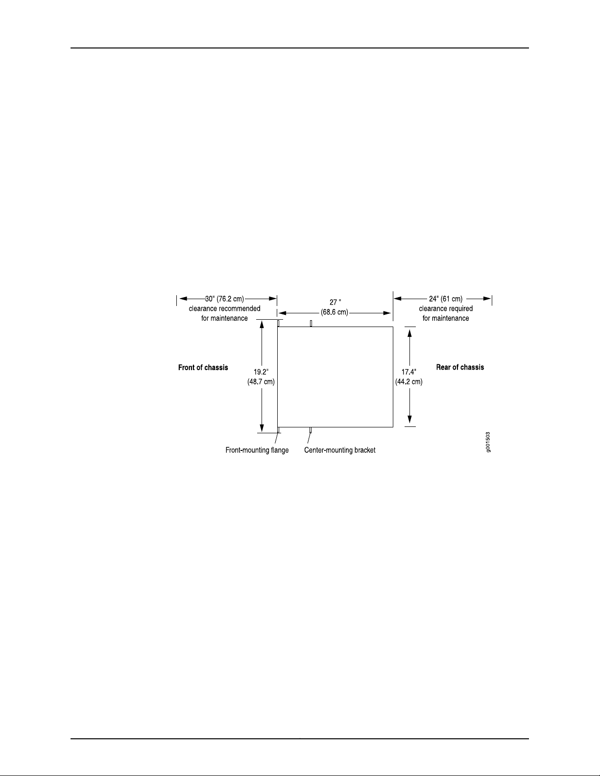
For service personnel to remove and install hardware components, there must be
adequate space at the front and back of the JCS1200 platform. Allow at least 24 in.
(61.0cm) both in front of and behind the JCS1200 platform.NEBS GR-63 recommends
at least 30 in. in front of the JCS1200 platform (see Figure 1 on page 4).
•
The rack or cabinet must have an adequate supply of cooling air.
•
In a closed cabinet, there must be a minimum of 6 in. (15.2 cm) of unobstructed airflow
behind the JCS1200 platform,or airflow bafflesmust be installed to prevent recirculation
of hot air and overheating.
Figure 1: Chassis Dimensions and ClearanceRequirementsfor the JCS1200
Platform
Tools Required to Install the JCS1200 Platform
•
A mechanical lift (strongly recommended)
•
7/16-in. hexagonal-head external drive socket wrench
•
1/2-in.or 13 mm open-end or socket wrench for removing chassis from pallet
•
Phillips (+) screwdriver, number 2
•
Antistatic mat
•
Wire cutters
•
Pliers
•
Electrostatic discharge (ESD) grounding wrist strap
•
Blank panels to cover any slots not occupied by a component
Copyright © 2010, Juniper Networks, Inc.4
Page 5

Step 2: Install the JCS1200 Mounting Hardware
•
Rack Mounting Hole Locations for the JCS1200 Platform on page 5
•
Install the JCS1200 Mounting Hardware in a Four-Post Rack or Cabinet on page 6
•
Install the JCS1200 Mounting Hardware in an Open-Frame Rack on page 7
Rack Mounting Hole Locations for the JCS1200 Platform
Table 1 on page 5 specifies the holes in which you insert mounting screws (and cage
nuts if needed) to install the mounting hardware required in a four-post or two-post
open-frame rack (an X indicates a mounting hole location).The hole distances are relative
to one of the standard U divisions on the rack. The bottom of all mounting shelves is at
0.04 in. (0.02 U) above a U division.
Table 1: Open-Frame Rack Mounting Hole Locations
Step 2: Install the JCS1200 Mounting Hardware
Large
ShelfDistance Above U DivisionHole
X9.86 U17.26 in. (43.8 cm)30
X8.86 U15.51 in. (39.4 cm)27
X2.86 U5.01 in. (12.7 cm)9
X1.86 U3.26 in. (8.3 cm)6
Small
ShelfChassis
XX7.86 U13.76 in. (34.9 cm)24
XX6.86 U12.01 in. (30.5 cm)21
XX5.86 U10.26 in. (26.0 cm)18
XX4.86 U8.51 in. (21.6 cm)15
XX3.86 U6.76 in. (17.1 cm)12
XX0.86 U1.51 in. (3.8 cm)3
XX0.50 U0.88 in. (2.2 cm)2
Related
Documentation
X0.14 U0.25 in. (0.6 cm)1
JCS1200 Platform Rack-Mounting Hardware•
• Rack-Mounting Requirements and Warnings for the JCS1200 Platform
• Installing the JCS1200 Mounting Hardware for a Four-Post Rack or Cabinet
• Installing the JCS1200 Mounting Hardware for an Open-Frame Rack
5Copyright © 2010, Juniper Networks, Inc.
Page 6
JCS1200 Platform: Quick Start
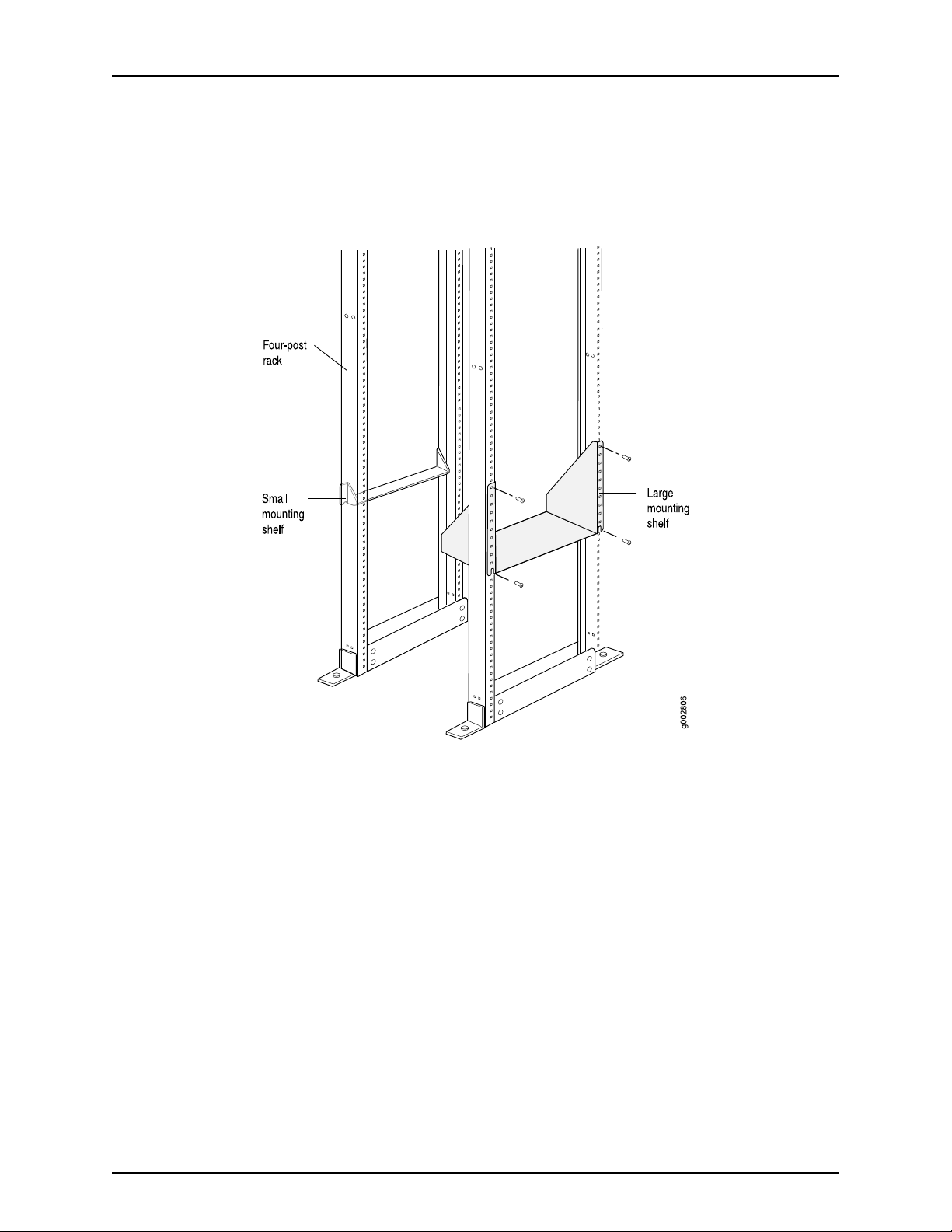
Install the JCS1200 Mounting Hardware in a Four-Post Rack or Cabinet
Figure 2: Install the JCS1200 Mounting Hardware for a Four-Post Rack or
Cabinet
To install the mounting hardware in a four-post rack or cabinet:
•
Install Cage Nuts in a Four-Post Rack or Cabinet, If Needed on page 6
•
Install the Large Mounting Shelf in a Four-Post Rack or Cabinet on page 7
•
Install the Small Mounting Shelf in a Four-Post Rack or Cabinet on page 7
•
Install the Mounting Brackets on the JCS1200 Platform on page 7
Install Cage Nuts in a Four-Post Rack or Cabinet, If Needed
For racks without threaded holes, you must install cage nuts in the locations specified in
Table 1 on page 5:
•
On each front rack rail, install cage nuts for the large shelf.
•
On each rear rack rail, install cage nuts for the small shelf.
Copyright © 2010, Juniper Networks, Inc.6
Page 7

Install the Large Mounting Shelf in a Four-Post Rack or Cabinet
Install the Large Mounting Shelf in a Four-Post Rack or Cabinet
1. On the front of each front rack rail, partially insert a mounting screw into the hole
containing the lowest cage nut.
2. Install the large shelf on the front rack rails. Rest the bottom slot of each ear on a
mounting screw.
3. Partially insert a mounting screw into the holes 3, 6, 9, and 30 in each ear of the large
shelf.
4. Tighten all the screws completely.
Install the Small Mounting Shelf in a Four-Post Rack or Cabinet
1. On the back side of each rear rack rail, partially insert a mounting screw into the hole
containing the lowest cage nut.
2. Install the small shelf on the back rack rails. Rest the bottom slot of each ear on a
mounting screw. The small shelf installs on the back of the rear rails, extending toward
the center of the rack. The bottom of the small shelf should align with the bottom of
the large shelf.
3. Partially insert screws into the open holes in the ears of the small shelf.
4. Tighten all the screws completely.
Install the Mounting Brackets on the JCS1200 Platform
Attach the front-mounting brackets to the side of the chassis using six of the mounting
screws provided.
Install the JCS1200 Mounting Hardware in an Open-Frame Rack
For open-frame racks, center-mounting provides more even weight distribution and
stability. The small mounting shelf is not needed for open-frame racks.
7Copyright © 2010, Juniper Networks, Inc.
Page 8
JCS1200 Platform: Quick Start
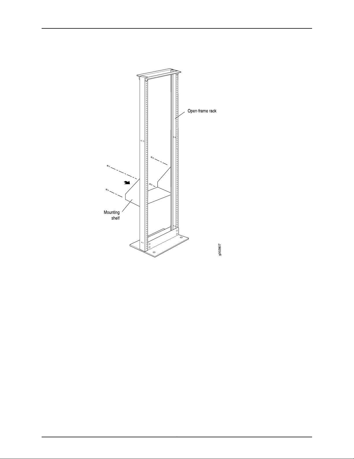
Figure 3: Install the JCS1200 Mounting Hardware for an Open-Frame Rack
To install the mounting hardware for an open-frame rack:
•
Install Cage Nuts in an Open-Frame Rack, If Needed on page 8
•
Install the Large Mounting Shelf in an Open-Frame Rack on page 8
•
Install the Mounting Brackets on the JCS1200 Platform on page 9
Install Cage Nuts in an Open-Frame Rack, If Needed
For racks without threaded holes, you must install cage nuts in the locations specified in
Table 1 on page 5:
•
On the rear side of rack rails, install cage nuts for the large shelf.
•
On the front side of rack rails, install cage nuts for the chassis.
Install the Large Mounting Shelf in an Open-Frame Rack
1. On the rear of each rack rail, partially insert a mounting screw into the highest hole
specified in Table 1 on page 5 for the large shelf
2. Install the large shelf on the rack. Hang the shelf over the mounting screws using the
keyhole slots located near the top of the large shelf flanges.
Copyright © 2010, Juniper Networks, Inc.8
Page 9

3. Partially insert screws into the rest of the holes specified in Table 1 on page 5 for
each ear of the large shelf.
4. Tighten all the screws completely.
Install the Mounting Brackets on the JCS1200 Platform
The JCS1200 platform is shipped with two front-mounting and two center-mounting
brackets.
•
If you plan to front-mount the chassis in an open-frame rack, attach the front-mounting
brackets to the side of the chassis using six of the mounting screws provided.
•
If you plan to center-mount the chassis in an open-frame rack, attach the
center-mounting brackets to the side of the chassis using the eight mounting screws
provided.
Step 3: Install the JCS1200 Platform
1. Read “Safety Warnings” on page 25.
Install the Mounting Brackets on the JCS1200 Platform
2. Remove components as described in “Remove Components from the JCS1200
Platform” on page 9.
3. Because of the JCS1200 platform's size and weight, we recommend you install the
chassis using a mechanical lift. Install the JCS1200 Platform as described in one of
the following subsections.
•
Install the JCS1200 Platform Using a Lift on page 10
•
Lift the JCS1200 Platform into the Rack or Cabinet on page 12
4. Reinstall the components as described in “Reinstall Components into the JCS1200
Platform” on page 13
Remove Components from the JCS1200 Platform
To reduce the weight of your JCS1200 platform, remove the following components from
the JCS1200 platform.
•
Fan modules
•
Fan shuttle
•
Management modules
•
Media trays
•
Power modules
•
Routing Engines
•
Switch modules
9Copyright © 2010, Juniper Networks, Inc.
Page 10

JCS1200 Platform: Quick Start
NOTE: For detailed instructions on removing JCS1200 components, see the
JCS1200 Control System Hardware Guide.
1. Attachan electrostatic discharge (ESD) grounding strap to your bare wrist, and connect
the strap to an approved site ESD grounding point. See the instructions for your site.
2. Slide each component out of the chassis evenly so that it does not become stuck or
damaged.
3. Label each component as you remove it so you can reinstall it in the correct location.
4. Immediately store each removed component in an electrostatic bag.
5. Do not stack removed components. Lay each one on a flat surface.
Install the JCS1200 Platform Using a Lift
1. If you are installing the platform in an open-frame rack, ensure that the rack is in its
permanent location and is secured to the building. Ensure that the installation site
allows adequate clearance for both airflow and maintenance. For details, see “Step
1: Prepare the Site” on page 3.
2. Load the JCS1200 platform onto the lift, making sure it rests securely on the lift
platform.
3. Using the lift, position the JCS1200 platform in front of the rack or cabinet, centering
it in front of the mounting shelves.
4. Lift the chassis approximately 0.75 in. (1.91 cm) above the surface of the mounting
shelves and position it as close as possible to the shelves.
5. Carefully slide the JCS1200 platform onto the mounting shelves so that the bottom
of the chassis and the mounting shelves overlap by approximately 2 in.
6. With two people pulling on the rear of the chassis and two people pushing on the
mounting flanges, slide the JCS1200 platform onto the mounting shelves until the
front or center-mounting flanges contact the rack rails. The shelves ensure that the
holes in the mounting flanges align with the holes in the rack rails.
7. Install a mounting screw into each of the open mounting holes in the rack-mounting
flanges to fasten the chassis to the rack, starting from the bottom.
8. Move the lift away from the rack.
9. Visually inspect the alignment of the JCS1200 platform. If the JCS1200 platform is
installed properly in the rack, all the mounting screws on one side of the rack should
be aligned with the mounting screws on the opposite side, and the platform should
be level.
Copyright © 2010, Juniper Networks, Inc.10
Page 11
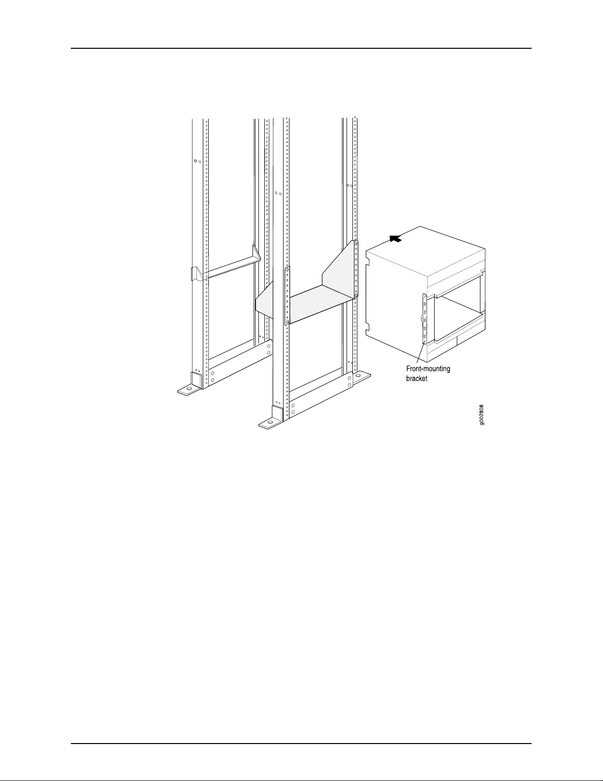
Install the JCS1200 Platform Using a Lift
Figure 4: Install the JCS1200 Platform in a Four-Post Rack
11Copyright © 2010, Juniper Networks, Inc.
Page 12

JCS1200 Platform: Quick Start
Figure 5: Install the JCS1200 Platform in an Open-Frame Rack
Lift the JCS1200 Platform into the Rack or Cabinet
Because of the JCS1200 platform's size and weight—up to 350 lb (158.8 kg) depending
on the configuration—we strongly recommend that you install the JCS1200 platform
using a mechanical lift, as described in “Install the JCS1200 Platform Using a Lift” on
page 10.
Lifting the chassis without a lift and mounting it in a rack requires four people. The empty
chassis weighs approximately 229 lb (99.82 kg).
1. Ensure the rack is in its permanent location and is secured to the building.
2. Position the JCS1200 platform in front of the rack or cabinet, centering it in front of
the mounting shelves. Use a pallet jack if one is available.
3. With two people in the front and two people in the back, hold onto the bottom of the
chassis and carefully lift it onto the mounting shelves.
4. Carefully slide the JCS1200 platform onto the mounting shelves so that the bottom
of the chassis and the mounting shelves overlap by approximately 2 in.
Copyright © 2010, Juniper Networks, Inc.12
Page 13

5. Install a mounting screw into each of the open mounting holes in the rack-mounting
flanges to fasten the chassis to the rack, starting from the bottom.
6. Visually inspect the alignment of the JCS1200 platform. If the JCS1200 platform is
installed properly in the rack, all the mounting screws on one side of the rack should
be aligned with the mounting screws on the opposite side, and the platform should
be level.
Reinstall Components into the JCS1200 Platform
NOTE: For detailed instructions on reinstalling JCS1200 components, see
the JCS1200 Control System Hardware Guide.
1. Attachan electrostatic discharge (ESD) grounding strap to your bare wrist, and connect
the strap to an approved site ESD grounding point. See the instructions for your site.
2. Slide each component into the chassis evenly so that it does not become stuck or
damaged.
Reinstall Components into the JCS1200 Platform
3. Tighten screws, as needed, for each component.
NOTE: Make sure that all empty slots are covered with a blank panel before
operating the JCS1200 platform.
Step 4: Connect the JCS1200 Platform to Power
•
Connect the JCS1200 AC Platform to AC Power on page 13
•
Connect the JCS1200 DC Platform to DC Power on page 13
Connect the JCS1200 AC Platform to AC Power
The JCS1200 platform has four AC power C20 input connectors. Use two C20/C19 type
AC jumper cords to connect AC power to the JCS1200 platform.
1. Attachan electrostatic discharge (ESD) grounding strap to your bare wrist, and connect
the strap to an approved site ESD grounding point. See the instructions for your site.
2. Connect one end of each power cord to a power connector on the rear of the JCS1200
platform.
3. Connect the other end of each power cord to a 200-240 volt, 20-amp power
distribution unit or appropriate electrical outlet. An external surge protective device
(SPD) is not required at the AC power input of the JCS1200 platform.
Connect the JCS1200 DC Platform to DC Power
The JCS1200 DC power inputs are configured for DC isolated return (DC-I). TheDC return
terminal or conductor is not connected to the equipment frame or the grounding means
of the equipment.
13Copyright © 2010, Juniper Networks, Inc.
Page 14

JCS1200 Platform: Quick Start
The JCS1200 DC platform has four DC power terminal connectors (see Figure 6 on
page 14). Each DC terminal has four M6 (0.25-inch) studs, one for –48 V DC, one for
RETURN (RTN), and two for connecting the grounding cable.
Figure 6: DC Power Terminal Connectors
To connect the JCS1200 DC platform to DC power:
1. Ensure that the voltage across the DC power source cable leads is 0 V and that there
is no chance that the cable leads might become active during installation.
2. Verify that a licensed electrician has attached the cable lugs to the power cables.
3. Switch both circuit breakers on the power supply faceplate to the off position (O).
4. Attach an electrostatic discharge (ESD) grounding strap to your bare wrist, and connect
the strap to an approved site ESD grounding point. See the instructions for your site.
5. Remove the terminal cover for each terminal:
a. Remove the two Phillips-head screws that attach the terminal cover to the DC
power box.
b. Pull the terminal cover away from the JCS1200 platform.
6. Attach the lugs on the DC source power cables to the terminal studs, making sure the
cables are not touching or in the way of any JCS1200 platform components. When
connecting a cable lug to each stud, install a flat washer on the stud, install the cable
lug, install a flat washer, install a split washer, and then install a nut (see Figure 7 on
page 15). Torque the wiring terminal nuts to 13.3 lb-in. (1.5 Nm).
Copyright © 2010, Juniper Networks, Inc.14
Page 15

Connect the JCS1200 DC Platform to DC Power
Figure 7: Attach the Cable Lugs to the DC Power Terminal Connectors
a. Attach the positive (+) DC source power cable lugs to the RTN (return) terminals.
b. Attach the negative (–) DC source power cable lugs to the –48V (input) terminals.
c. Attach the safety ground wire to the other two terminals (GND).
7. Verify that the power and ground cabling are correct.
8. Replace the terminal cover for each terminal:
a. Orient the terminal cover so that the terminal cover fits over the DC power terminals
and the screw holes on the terminal cover are aligned with the screw holes on the
DC power box.
b. Install two Phillips-head screws that attach the terminal cover to the DC power
box.
15Copyright © 2010, Juniper Networks, Inc.
Page 16

JCS1200 Platform: Quick Start
CAUTION: Only trained service personnel other than Juniper Networks service
technicians are authorized to make the connections to and disconnections
from the –48 volt DC power source. Juniper Networks service technicians are
not certified or authorized to install or remove the –48 volt power cable. The
customer is responsible for ensuring that only trained service personnel install
or remove the –48 volt power cable.
The following guidelines are provided for connecting a 60-A JCS1200 platform to a –48
V DC power source:
•
The power source must have a minimum of 80 A overcurrent protection. See article
240, paragraph 3, table 310-16 of the National Electric Code for more information about
electrical wiring requirements.
•
The overcurrent protective device or circuit breaker must be accessible to service
personnel to prevent the power from being turned on by someone other than a
technician servicing the JCS1200 platform.
Related
Documentation
•
The JCS1200 platform requires a DC wire rating of 4 AWG (circular mil area of
33100-52600) and of 90° C.
NOTE: The actual wire gauge and ring terminal are determined by the
current draw and the length of wire run or as specified by the customer
premises guidelines.
•
Flexible DC wiring is recommended to allow for minimum bend radius.
•
The supply wiring to the power connectors must be terminated in UL-recognized
insulated ring terminals, sized for an M6 stud, 4 AWG wire (circular mil area of
33100-52600), and a wire insulation diameter of 12.8 to 13.1 mm. An example of this
type of ring terminal is Amp Plasti-Grip type 520431 using Tyco Electronics Hydraulic
Crimping Tool part number 14907491.
•
For NEBS compliance, the grounding cable must use copper conductors with a size
minimum of 6 AWG (circular mil area of 2080033100) and must be terminated in a
UL-recognized two-hole lug sized for an M6 stud. An example of this type of two-hole
lug is the Thomas and Betts part number 54205 using the Thomas and Betts crimping
tool model TBM-25S.
•
Torque the wiring-terminal nuts to 13.3 lb-in. (1.5 Nm).
For safety information, see Safety Warnings on page 25.•
Copyright © 2010, Juniper Networks, Inc.16
Page 17

Step 5: Connect the JCS1200 Platform
•
Tools and Parts Required to Connect the JCS1200 Platform on page 17
•
Connect the JCS1200 Management Module to the Network on page 17
•
Connect a Console to the JCS1200 Routing Engines on page 20
Tools and Parts Required to Connect the JCS1200 Platform
To connect the JCS1200 platform to T Series Core routers, power, and management
devices and to power on the platform, you need the following tools and parts:
•
10-mm. hexagonal-head external drive socket wrench, or nut driver, with torque at
13.3 lb-in. (1.5 Nm), for tightening nuts to terminal studs on each terminal connector
on a DC-powered platform.
CAUTION: Do not substitute a non metric nut driver or wrench. A tool that
does not fit the nuts exactly can damage them. If a 10-mm. tool is not
available, use pliers or an adjustable wrench.
Step 5: Connect the JCS1200 Platform
•
Wire cutters
•
Pliers
•
Electrostatic discharge (ESD) grounding wrist strap
Connect the JCS1200 Management Module to the Network
The management module supports network connection through an Ethernet port or a
serial port (see Figure 8 on page 17).
Figure 8: Ports on the Management Module
For direct connection of a computer to the management module Ethernet port, you need
a Category 5 or higher Ethernet cable.
Network connections through the serial port may require an Advanced Management
Module (AMM) adapter.For more information, see the JCS1200 Control System Hardware
Guide.
The following topics describe how to make typical connections to a management module:
•
Connect the JCS1200 Management Module to the Network Through a Network Ethernet
Connection on page 18
•
Connect the JCS1200 Management Module to a Client Computer Through an Ethernet
Connection on page 18
17Copyright © 2010, Juniper Networks, Inc.
Page 18

JCS1200 Platform: Quick Start
•
Connect the JCS1200 Management Module to the Network Through a Serial
Connection on page 18
•
Connect the JCS1200 Management Module to a Client Computer Through a Serial
Connection on page 19
Connect the JCS1200 Management Module to the Network Through a Network Ethernet Connection
1. Attachan electrostatic discharge (ESD) grounding strap to your bare wrist, and connect
the strap to one of the ESD points on the chassis.
2. Connect one end of an Ethernet cable to the Ethernet port on the management module.
See Figure 8 on page 17 for the location of ports on the management module.
3. Connect the other end of the Ethernet cable to the network.
4. Check the Ethernet LEDs to make sure that the network connection is working.
•
A lit green Ethernet LINK LED indicates that there is an active connection through
the port to the network.
•
A flashing green Ethernet activity (TX/RX) LED indicates that there is activity through
the port over the network link.
Connect the JCS1200 Management Module to a Client Computer Through an Ethernet Connection
1. Attachan electrostatic discharge (ESD) grounding strap to your bare wrist, and connect
the strap to one of the ESD points on the chassis.
2. Connect one end of a Category 5 or higher Ethernet cable to the Ethernet port on the
management module. See Figure 8 on page 17 for the location of ports on the
management module.
3. Connect the other end of the Ethernet cable to the Ethernet port on the client
computer.
4. Check the Ethernet LEDs to make sure that the network connection is working.
•
A lit green Ethernet LINK LED indicates that there is an active connection through
the port to the network.
•
A flashing green Ethernet activity (TX/RX) LED indicates that there is activity through
the port over the network link.
For information about establishing a connection to the management module for the first
time, see the JCS1200 Control System Hardware Guide.
Connect the JCS1200 Management Module to the Network Through a Serial Connection
1. Attachan electrostatic discharge (ESD) grounding strap to your bare wrist, and connect
the strap to one of the ESD points on the chassis.
2. Plug one end of an RJ-45 serial cable into the serial port on the management module.
See Figure 8 on page 17 for the location of ports on the management module.
Copyright © 2010, Juniper Networks, Inc.18
Page 19

Connect the JCS1200 Management Module to a Client Computer Through a Serial Connection
NOTE: Some consoles require that you use an AMM adapter. If needed,
plug an AMM adapter into the serial port on the management module,
and then connect the serial cable. For information about the AMM adapter
pinouts, see the JCS1200 Control System Hardware Guide.
3. Connect the other end of the serial cable to your console.
Connectthe JCS1200 Management Module to a Client Computer Through a Serial
Connection
1. Attachan electrostatic discharge (ESD) grounding strap to your bare wrist, and connect
the strap to one of the ESD points on the chassis.
2. Plug one end of an RJ-45 serial cable into the serial port on the management module.
See Figure 8 on page 17 for the location of ports on the management module.
NOTE: For the serial cable characteristics,see the JCS1200 Control System
Hardware Guide.
3. Connect the other end of the serial cable to the serial connector of the client computer,
such as a notebook computer.
4. Configure the serial port of the client computer to the following values:
•
Baud rate—57600
•
Parity—none
•
Stop bits—1
For information about establishing a connection to the management module for the first
time, see the JCS1200 Control System Hardware Guide.
19Copyright © 2010, Juniper Networks, Inc.
Page 20

JCS1200 Platform: Quick Start
Connect a Console to the JCS1200 Routing Engines
To access the Routing Engines from a console, you must use the serial port breakout
cable provided with the chassis to connect the JCS1200 platform. The breakout cable
provides a direct serial interface to each Routing Engine in the JCS1200 platform and
contains 14 RJ-45 serial cable connectors (see Figure 9 on page 20).
Figure 9: Serial Port Breakout Cable
NOTE: Only 12 of the 14 RJ-45 serial cable connectors are used to connect
the console to the Routing Engines. Connectors 13 and 14 are reserved for
future use.
To connect the console:
1. Attachan electrostatic discharge (ESD) grounding strap to your bare wrist, and connect
the strap to an approved site ESD grounding point. See the instructions for your site.
2. Connect the serial connector on the cable to the serial port connector on the alarm
panel module of the JCS1200 platform.
3. Connect the each of the RJ-45 connectors on the cable to your console.
NOTE: Some consoles require that you use a CPU adapter. If needed,
connect a CPU adapter to each of the 12 RJ-45 connectors on the breakout
cable. Then connect each CPU adapter to your console. For information
about the CPU adapter pinouts, see the JCS1200 Control SystemHardware
Guide.
Step 6: Integrate an Offline T Series Core Router with the JCS1200 Platform
You can connect up to three of the following T Series Core routers running Junos OS
Release 9.2 or later to the JCS1200 platform: T320 router, T640 routing node, and T1600
Copyright © 2010, Juniper Networks, Inc.20
Page 21

routing node. The following procedures describe connecting the JCS1200 platform to a
T Series Core router:
•
Replace the Standard CBs in the T Series Core Router on page 21
•
Connect an Offline T Series Core Router to the JCS1200 Platform on page 21
Replace the Standard CBs in the T Series Core Router
Before you connect an offline T Series Core router to the JCS1200 platform, you must
replace the standard control boards (CBs) with T-CBs. To replace the CBs with T-CBs:
1. If the routing platformis poweredon, issue the request system halt both-routing-engines
operationalmode command from the console or other management device connected
to the routing platform. The command shuts down the Routing Engines cleanly, so
their state information is preserved.
user@host> request system halt both-routing-engines
Wait until a message appears on the console confirming that the operating system
has halted.For more information about the command, see the Junos OS SystemBasics
and Services Command Reference.
Replace the Standard CBs in the T Series Core Router
2. Attach an electrostatic discharge (ESD) grounding strap to your bare wrist, and connect
the strap to one of the ESD points on the chassis.
3. Switch both circuit breakers on each power supply faceplate to the off position (O).
NOTE: The CBs and T-CBs are hot-removable and hot-insertable if the
routing node contains redundant host subsystems. However, we
recommend that you power off the routing platform before you replace
the CBs and T-CBs.
4. Set the switches on each T-CB:
•
Set the chassis ID switch to 0. You must use the same chassis ID on each T-CB.
•
Set the M/S switch on the T-CB faceplate to S.
5. Replace each CB with a T-CB. Use the standard replacement procedure described in
the hardware guide for your routing platform.
6. You can optionally upgrade the Routing Engines in the routing platform. To replace
each Routing Engine, follow the standard replacement procedure described in the
hardware guide for your routing platform.
Connect an Offline T Series Core Router to the JCS1200 Platform
After you replace the CBs with T-CBs, you connect each T-CB on the T Series Core router
to each switch module on the JCS1200 platform. Figure 10 on page 22 shows the location
of the switch modules on the JCS1200 platform.
21Copyright © 2010, Juniper Networks, Inc.
Page 22

JCS1200 Platform: Quick Start
Figure 10: Location of Switch Modules on the JCS1200 Platform
To connect the T-CBs (see Figure 11 on page 23):
1. Attachan electrostatic discharge (ESD) grounding strap to your bare wrist, and connect
the strap to one of the ESD points on the chassis.
2. Plug an Ethernet adapter (ETH) into the top RJ-45 port (labeled 1) of switch module
1 on the JCS1200 platform.
3. Connect one end of a UTP Category 5 cable to the Ethernet adapter.
4. Plug the other end of the cable into the port labeled CIP on T-CB-0. Dress the cable
appropriately.
NOTE: The RJ-45 port labeled AUX on a T-CB is reserved for future use.
5. If you installed a redundant switch module into switch module bay 2:
a. Plug an ETH adapter into the top RJ-45 port (labeled 1) of switch module 2 on the
JCS1200 platform.
b. Connect one end of a UTP Category 5 cable to the Ethernet adapter.
c. Plug the other end of the cable into the port labeled CIP on T-CB-1. Dress the cable
appropriately.
Copyright © 2010, Juniper Networks, Inc.22
Page 23

Connect an Offline T Series Core Router to the JCS1200 Platform
Figure 11: Connect the JCS1200 Platform to a T Series Core Router
NOTE: Six ports are identified as EXT1, EXT2, EXT3, EXT4, EXT5, and EXT6
in the switch configuration menus and are labeled 1 through 6 (from top to
bottom) on the switch module. The ports labeled 4 and 5 on the switch
module are reserved for future use. Port 6 connects to the management ports
on all the Routing Engines in the JCS chassis.
•
The copper model of the Gigabit Ethernet switch module has six external
copper 1000BASE-T Ethernet ports. You can use RJ-45 ports labeled 1
through 3 to connect up to three T Series routers running Junos OS Release
9.2 and later to the JCS1200 platform.
•
The fiber model of the Gigabit Ethernet switch module has six external
1000BASE-LX SFP transceiver ports. (For interface specifications, see
Gigabit Ethernet 1000BASE-LX Interface Specifications.) You can use the
SFP ports labeled 1 through 3 to connect over the network to route reflector
applications.
NOTE: The connections between the switch modules and the T-CBs are
proprietary Ethernet connections. Do not attempt to connect these
components through a switch or hub.
23Copyright © 2010, Juniper Networks, Inc.
Page 24

JCS1200 Platform: Quick Start
Step 7: Power On the T Series Core Router
After you have connected the control planes between the T Series Core router and the
JCS1200 platform, power on the routing platform, monitor the boot process, and verify
the connections. Follow this procedure:
1. Attachan electrostatic discharge (ESD) grounding strap to your bare wrist, and connect
the strap to one of the ESD points on the chassis.
2. Switch the circuit breakers on one of the power supplies to the on position (|) and
observe the LEDs on the power supply faceplate. If the power supply is correctly
installed and is functioning properly, the DC OK LED lights steadily, and the CB ON
LED blinks momentarily, then lights steadily.
NOTE: After powering off a power supply, wait at least60 seconds before
powering it back on. After powering on a power supply, wait at least 60
seconds before powering it off.
If the system is completely powered off when you power on the power
supply, the Routing Engine boots as the power supply completes its startup
sequence. If the Routing Engine finishes booting and you need to power
off the system again, first issue the CLI request system halt command.
After a power supply is poweredon, it can take up to 60 seconds for status
indicators—such as the output status LEDs on the power supply, the
show chassis command display, and messages on the LCD on the craft
interface—to indicatethat the power supply is functioning normally. Ignore
error indicators that appear during the first 60 seconds.
3. Repeat Step 2 for the remaining power supply.
4. On an external management device connected to the console or auxiliary port of the
CIP, monitor the startup process to verify that the system has booted properly.
NOTE: You do not need to reboot the JCS1200 platform after the routing
platform has booted.
Step 8: Configure the Software for the JCS1200 Platform
The JCS1200 platform ships with one preconfigured management module but you can
install and configure a second management module for redundancy. The Routing Engines
are preconfigured with Junos OS. Perform general configuration of the JCS1200 platform
and installed components through the management module. See the Junos OS Protected
System Domain Configuration Guide for information and instructions. Some components
Copyright © 2010, Juniper Networks, Inc.24
Page 25

in the JCS1200 platform, such as management modules and Routing Engines, might also
require additional configuration:
•
Configure the JCS1200 Management Module on page 25
•
Configure the JCS1200 Routing Engines on page 25
Configure the JCS1200 Management Module
All management modules are preconfigured with the same static IP address. You can
use the management module user interface to assign a new static IP address. To establish
connectivity, the management module attempts to use Dynamic Host Configuration
Protocol (DHCP) to acquire its initial IP address for the management module Ethernet
port. If DHCP is not installed or is enabled and fails, the management module uses the
static IP address. Use the management module to configure other JCS1200 component
settings, such as user accounts, DHCP,or wake on LAN. For information about configuring
the management module, see the Junos OS Protected System Domain Configuration
Guide.
Configure the JCS1200 Routing Engines
Configure the JCS1200 Management Module
Safety Warnings
To achieve Routing Engine redundancy, you must configure the Ethernet controllers in
one or more Routing Engines for failover. When failover occurs on a Routing Engine, the
secondary Ethernet controller takes over network communications, using the JCS1200
switch module that is associated with that controller. Install a pair of JCS1200 switch
modules in switch module bays 1 and 2, and then configure them and your network
infrastructure so that they can direct traffic to the same destinations. For information
about configuring the Routing Engines, see the Junos OS Protected System Domain
Configuration Guide.
WARNING: See installation instructions beforeconnecting the platform.This
is a summary of safety warnings. For a complete list of warnings for this
platform, including translations, see the JCS1200 Control System Hardware
Guide at http://www.juniper.net/techpubs/hardware/.
WARNING: The intrabuilding port(s) of the router is suitable for connection
to intrabuilding or unexposed wiring or cabling only. The intrabuilding port(s)
of the router MUST NOT be metallically connected to interfaces that connect
to the OSP or its wiring. These interfaces are designed for use as intrabuilding
interfaces only (Type 2 or Type 4 ports as described in GR-1089-CORE, Issue
4) and require isolation from the exposed OSP cabling. The addition of primary
protectors is not sufficient protection to connect these interfaces metallically
to OSP wiring.
25Copyright © 2010, Juniper Networks, Inc.
Page 26

JCS1200 Platform: Quick Start
CAUTION: Before removing or installing components of a router, attach an
ESD strap to an ESD point and place the other end of the strap around your
bare wrist. Failure to use an ESD strap could result in damage to the platform.
•
Only trained and qualified personnel should install or replace the platform.
•
Performonly the procedures described in this Quick Start or the JCS1200 Control System
Hardware Guide. Other services should be performed by authorized service personnel
only.
•
Read the installation instructions before you connect the platform to a power source.
•
Before installing the platform, read the guidelines for site preparation in the JCS1200
Control SystemHardware Guide to make sure that the site meets power, environmental,
and clearance requirements for the platform.
•
When installing the platform, do not use a ramp inclined more than 10 degrees.
•
Manually installing the platform requires four people to lift. Before lifting the chassis,
remove components and attach the installation handle as described in the JCS1200
Control System Hardware Guide. To prevent injury, keep your back straight and lift with
your legs, not your back.
•
Mount the platform at the bottom of the rack if it is the only unit in the rack.
•
When mounting the platform in a partially filled rack, load the rack from the bottom
to the top, with the heaviest component at the bottom of the rack.
•
If the rack is provided with stabilizing devices, install the stabilizers before mounting
or servicing the platform in the rack.
•
When removing or installing an electrical component, always place it component-side
up on a flat antistatic surface or in an electrostatic bag.
•
When you install the platform, alwaysmake the ground connection first and disconnect
it last.
•
Wire the DC power supply using the appropriate lugs. When connecting power, the
proper wiring sequence is ground to ground, +RTN to +RTN, then –48 V to –48 V.When
disconnecting power, the proper wiring sequence is –48 V to –48 V, +RTN to +RTN,
then ground to ground. Always connect the ground wire first and disconnect it last.
•
Do not work on the system or connect or disconnect cables during electrical storms.
•
Beforeworking on equipment that is connected to power lines, remove jewelry, including
rings, necklaces, and watches. Metal objects heat up when connected to power and
ground and can cause serious burns or become welded to the terminals.
•
Failure to observe these safety warnings can result in serious physical injury.
Copyright © 2010, Juniper Networks, Inc.26
Page 27

Safety Warnings
WARNING: Electrical current from power, telephone, and communication
cables is hazardous.
To avoid a shock hazard:
•
Do not connect or disconnect any cables or perform installation,
maintenance, or reconfiguration of this product during an electrical storm.
•
Connect all power cords to a properly wired and grounded power source.
•
Connect to properly wired power sources any equipment that will be
attached to this product.
•
When possible, use one hand only to connect or disconnect signal cables.
•
Never power on any equipment when there is evidence of fire, water, or
structural damage.
•
Disconnect the attached AC power cords, DC power sources, network
connections, telecommunications systems, and serial cables before you
open the component covers, unless you are instructed otherwise in the
installation and configuration procedures.
•
Connect and disconnect cables as described in the following procedures
when you install, move, or open covers on this product or attached
components.
To connect power sources:
1. Turn OFF all power sources and equipment that are to be attached to
this product.
2. Attach signal cables to the product.
3. Attach power cords to product.
•
For AC systems, use appliance inlets.
•
For DC systems,ensure correct polarity of –48 V DC connections: RTN
is + and –48 V DC is –. Earth ground should use a two-hole lug for
safety.
4. Attach signal cables to other components.
5. Connect power cords to their sources.
6. Turn ON all the power sources.
To disconnect power sources:
1. Turn OFF all power sources and equipment that are attached to this
product.
•
For AC systems, remove all power cords from the chassis power
receptacles for interrupt power at the AC power distribution unit.
27Copyright © 2010, Juniper Networks, Inc.
Page 28

JCS1200 Platform: Quick Start
•
For DC systems, disconnect DC power sources at the breaker panel
or by turning off the power source. Then remove the DC cables.
2. Remove signal cables from connectors.
3. Remove all cables from components.
WARNING:
When installing laser products (such as fiber-optic devices or transmitters),
note the following:
•
Do not remove the covers. Removing the covers of the laser product could
result in exposure to hazardous laser radiation. There are no serviceable
parts inside the component.
•
Use of controls or adjustments or performance of procedures other than
those specified here might result in hazardous radiation exposure.
WARNING: Some laser products contain an embedded Class 3A or Class 3B
laser diode. Note the following:
There is laser radiation when open. Do not stare into the beam, do not view
directly with optical instruments, and avoid direct exposure to the beam.
CAUTION: The powercontrol button on the component and the power switch
on the power supply do not turn off the electrical current supplied to the
component. The component also might have more than one power cord. To
removeall electrical current from the component, disconnect all powercords
from the power source.
CAUTION: Hazardous energy is present when the Routing Engine is connected
to the power source. Always replace the Routing Engine cover before installing
the Routing Engine.
WARNING: Handling the cord on this product or cords associated with
accessories sold with this product, will expose you to lead, a chemical known
Copyright © 2010, Juniper Networks, Inc.28
Page 29

Compliance Statements for NEBS for JCS1200 Platforms
to the State of California to cause cancer, and birth defects or other
reproductive harm. Wash hands after handling.
ADVERTENCIA: El contacto con el cable de este producto o con cables de
accesorios que se venden junto con este producto, pueden exponerle al
plomo, un elemento qumico que en el estado de California de los Estados
Unidos est considerado como un causantede cancer y de defectoscongnitos,
adems de otros riesgos reproductivos. Lvese las manos despus de usar el
producto.
Compliance Statements for NEBS for JCS1200 Platforms
•
The equipment is suitable for installation as part of the Common Bonding Network
(CBN).
•
The equipment is suitable for installation in locations where the National Electrical
Code (NEC) applies.
•
The battery return connection is to be treated as an isolated DC return (i.e. DC-I), as
defined in GR-1089-CORE.
Compliance Statements for EMC Requirements for the JCS1200 Platform
•
Australia and New Zealand on page 29
•
Canada on page 29
•
China on page 30
•
European Community on page 30
•
Declaration of Conformity on page 30
•
Japan on page 31
•
Taiwan on page 32
•
United Kingdom on page 32
•
United States on page 32
Australia and New Zealand
CAUTION: This is a Class A product. In a domestic environment this product
may cause radio interference, in which case the user may be required to take
adequate measures.
Canada
This Class A digital apparatus complies with Canadian ICES-003.
Cet appareil numérique de la classe A est conforme à la norme NMB-003 du Canada.
29Copyright © 2010, Juniper Networks, Inc.
Page 30

JCS1200 Platform: Quick Start
China
European Community
This product is in conformity with the protection requirements of EU Council Directive
89/336/EEC on the approximation of the laws of the Member States relating to
electromagnetic compatibility. Juniper Networks cannot accept responsibility for any
failure to satisfy the protection requirements resulting from a nonrecommended
modification of the product, including the fitting of non-Juniper Networks option cards.
This product has been tested and found to comply with the limits for Class A Information
Technology Equipment according to CISPR 22/European Standard EN 55022. The limits
for Class A equipment were derived for commercial and industrial environments to provide
reasonable protection against interference with licensed communication equipment.
Declaration of Conformity
Figure 12 on page 31 shows the Declaration of Conformity for the router.
CAUTION: This is a Class A product. In a domestic environment this product
may cause radio interference in which case the user may be required to take
adequate measures.
Copyright © 2010, Juniper Networks, Inc.30
Page 31

Compliance Statements for EMC Requirements for the JCS1200 Platform
Figure 12: JCS1200 Declaration of Conformity
Japan
Translation from Japanese—This is a Class A product. In a domestic environment this
product may cause radio interference in which case the user may be required to take
adequate measures. VCCI-A
31Copyright © 2010, Juniper Networks, Inc.
Page 32

JCS1200 Platform: Quick Start
Taiwan
United Kingdom
This apparatus is approved under approval number NS/G/1234/J/100003 for indirect
connection to public telecommunication systems in the United Kingdom.
United States
This equipment has been tested and found to comply with the limits for a Class A digital
device, pursuant to Part 15 of the FCC Rules. These limits are designed to provide
reasonable protection against harmful interference when the equipment is operated in
a commercial environment. This equipment generates, uses, and can radiate radio
frequency energy and, if not installed and used in accordance with the instruction manual,
may cause harmful interference to radio communications. Operation of this equipment
in a residential area is likely to cause harmful interference, in which case the user will be
required to correct the interference at his own expense.
Properly shielded and grounded cables and connectors must be used in order to meet
FCC emission limits. Juniper Networks is not responsible for any radio or television
interference caused by using other than recommended cables and connectors or by
unauthorized changes or modifications to this equipment. Unauthorized changes or
modifications could void the user's authority to operate the equipment.
This device complies with Part 15 of the FCC Rules. Operation is subject to the following
two conditions: (1) this device may not cause harmful interference, and (2) this device
must accept any interference received, including interference that may cause undesired
operation.
Junos Documentation and Release Notes
For a list of related Junos documentation, see
http://www.juniper.net/techpubs/software/junos/ .
If the information in the latest release notes differs from the information in the
documentation, follow the Junos Release Notes.
Copyright © 2010, Juniper Networks, Inc.32
Page 33

To obtain the most current version of all Juniper Networks®technical documentation,
see the product documentation page on the Juniper Networks website at
http://www.juniper.net/techpubs/.
Requesting Technical Support
Technical product support is available through the Juniper Networks Technical Assistance
Center (JTAC). If you are a customer with an active J-Care or JNASC support contract,
or are covered under warranty, and need postsales technical support, you can access
our tools and resources online or open a case with JTAC.
•
JTAC policies—For a complete understanding of our JTAC procedures and policies,
review the JTAC User Guide located at
http://www.juniper.net/us/en/local/pdf/resource-guides/7100059-en.pdf .
•
Product warranties—For product warranty information, visit
http://www.juniper.net/support/warranty/ .
•
JTAC Hours of Operation —The JTAC centers have resources available 24 hours a day,
7 days a week, 365 days a year.
Requesting Technical Support
Self-Help Online Tools and Resources
For quick and easy problem resolution, Juniper Networks has designed an online
self-service portal called the Customer Support Center (CSC) that provides you with the
following features:
•
Find CSC offerings: http://www.juniper.net/customers/support/
•
Find product documentation: http://www.juniper.net/techpubs/
•
Find solutions and answer questions using our Knowledge Base: http://kb.juniper.net/
•
Download the latest versions of software and review release notes:
http://www.juniper.net/customers/csc/software/
•
Search technical bulletins for relevant hardware and software notifications:
https://www.juniper.net/alerts/
•
Join and participate in the Juniper Networks Community Forum:
http://www.juniper.net/company/communities/
•
Open a case online in the CSC Case Management tool: http://www.juniper.net/cm/
To verify service entitlement by product serial number, use our Serial Number Entitlement
(SNE) Tool: https://tools.juniper.net/SerialNumberEntitlementSearch/
Opening a Case with JTAC
You can open a case with JTAC on the Web or by telephone.
•
Use the Case Management tool in the CSC at http://www.juniper.net/cm/ .
•
Call 1-888-314-JTAC (1-888-314-5822 toll-free in the USA, Canada, and Mexico).
33Copyright © 2010, Juniper Networks, Inc.
Page 34

JCS1200 Platform: Quick Start
Revision History
For international or direct-dial options in countries without toll-free numbers, visit us at
http://www.juniper.net/support/requesting-support.html
June 2010—530-035420. Added information about connecting multiple T Series Core
routers running Junos OS Release 9.2 or later. Added information about the fiber-optic
switch module.
18 April 2008—530-023227-01. Revision 1.
Copyright © 2010, Juniper Networks, Inc. All rights reserved.
Juniper Networks, Junos, Steel-Belted Radius, NetScreen, and ScreenOS are registered trademarks of Juniper Networks, Inc. in the United
States and other countries. The Juniper Networks Logo, the Junos logo, and JunosE are trademarks of Juniper Networks, Inc. All other
trademarks, service marks, registered trademarks, or registered service marks are the property of their respective owners.
Juniper Networks assumes no responsibility for any inaccuracies in this document. Juniper Networks reserves the right to change, modify,
transfer, or otherwise revise this publication without notice.
Products made or sold by Juniper Networks or components thereof might be covered by one or more of the following patents that are
owned by or licensed to Juniper Networks: U.S. Patent Nos. 5,473,599, 5,905,725, 5,909,440, 6,192,051, 6,333,650, 6,359,479, 6,406,312,
6,429,706, 6,459,579, 6,493,347, 6,538,518, 6,538,899, 6,552,918, 6,567,902, 6,578,186, and 6,590,785.
Copyright © 2010, Juniper Networks, Inc.34
 Loading...