

Page 1

J2320, J2350, J4350, and J6350 Services Router
Getting Started Guide
Release 8.4
Juniper Networks, Inc.
1194 North Mathilda Avenue
Sunnyvale, California 94089
USA
408-745-2000
www.juniper.net
Part Number: 530-020998-01, Revision 1
Page 2

This product includes the Envoy SNMP Engine, developed by Epilogue Technology, an Integrated Systems Company. Copyright © 1986-1997, Epilogue
Technology Corporation. All rights reserved. This program and its documentation were developed at private expense, and no part of them is in the public
domain.
This product includes memory allocation software developed by Mark Moraes, copyright © 1988, 1989, 1993, University of Toronto.
This product includes FreeBSD software developed by the University of California, Berkeley, and its contributors. All of the documentation and software
included in the 4.4BSD and 4.4BSD-Lite Releases is copyrighted by the Regents of the University of California. Copyright © 1979, 1980, 1983, 1986, 1988,
1989, 1991, 1992, 1993, 1994. The Regents of the University of California. All rights reserved.
GateD software copyright © 1995, the Regents of the University. All rights reserved. Gate Daemon was originated and developed through release 3.0 by
Cornell University and its collaborators. Gated is based on Kirton’s EGP, UC Berkeley’s routing daemon (routed), and DCN’s HELLO routing protocol.
Development of Gated has been supported in part by the National Science Foundation. Portions of the GateD software copyright © 1988, Regents of the
University of California. All rights reserved. Portions of the GateD software copyright © 1991, D. L. S. Associates.
This product includes software developed by Maker Communications, Inc., copyright © 1996, 1997, Maker Communications, Inc.
Juniper Networks, the Juniper Networks logo, NetScreen, and ScreenOS are registered trademarks of Juniper Networks, Inc. in the United States and other
countries. JUNOS and JUNOSe are trademarks of Juniper Networks, Inc. All other trademarks, service marks, registered trademarks, or registered service
marks are the property of their respective owners.
Juniper Networks assumes no responsibility for any inaccuracies in this document. Juniper Networks reserves the right to change, modify, transfer, or
otherwise revise this publication without notice.
Products made or sold by Juniper Networks or components thereof might be covered by one or more of the following patents that are owned by or licensed
to Juniper Networks: U.S. Patent Nos. 5,473,599, 5,905,725, 5,909,440, 6,192,051, 6,333,650, 6,359,479, 6,406,312, 6,429,706, 6,459,579, 6,493,347,
6,538,518, 6,538,899, 6,552,918, 6,567,902, 6,578,186, and 6,590,785.
J2320, J2350, J4350, and J6350 Services Router Getting Started Guide
Release 8.4
Copyright © 2007, Juniper Networks, Inc.
All rights reserved. Printed in USA.
Writing: Nidhi Bhargava, Michael Bushong, Maya Devi, Taffy Everts, Elizabeth Gardner, Walter Goralski, Joshua Kim, Jerry Isaac, Archana Maheshwari,
Hareesh Kumar Kozhippurath Narayana Panicker, Laura Phillips, Cheryl Potter, Frank Reade, Swapna Steiger, Selvakumar T. S., Alan Twhigg, and Keldyn
West
Editing: Taffy Everts and Stella Hackell
Illustration: Faith Bradford Brown and Nathaniel Woodward
Cover Design: Edmonds Design
Revision History
29 June 2007—Revision 1.
The information in this document is current as of the date listed in the revision history.
YEAR 2000 NOTICE
Juniper Networks hardware and software products are Year 2000 compliant. The JUNOS software has no known time-related limitations through the year
2038. However, the NTP application is known to have some difficulty in the year 2036.
SOFTWARE LICENSE
The terms and conditions for using this software are described in the software license contained in the acknowledgment to your purchase order or, to the
extent applicable, to any reseller agreement or end-user purchase agreement executed between you and Juniper Networks. By using this software, you
indicate that you understand and agree to be bound by those terms and conditions. Generally speaking, the software license restricts the manner in which
you are permitted to use the software and may contain prohibitions against certain uses. The software license may state conditions under which the license
is automatically terminated. You should consult the license for further details. For complete product documentation, please see the Juniper Networks Web
site at www.juniper.net/techpubs.
ii ■
Page 3

End User License Agreement
READ THIS END USER LICENSE AGREEMENT (“AGREEMENT”) BEFORE DOWNLOADING, INSTALLING, OR USING THE SOFTWARE. BY DOWNLOADING,
INSTALLING, OR USING THE SOFTWARE OR OTHERWISE EXPRESSING YOUR AGREEMENT TO THE TERMS CONTAINED HEREIN, YOU (AS CUSTOMER
OR IF YOU ARE NOT THE CUSTOMER, AS A REPRESENTATIVE/AGENT AUTHORIZED TO BIND THE CUSTOMER) CONSENT TO BE BOUND BY THIS
AGREEMENT. IF YOU DO NOT OR CANNOT AGREE TO THE TERMS CONTAINED HEREIN, THEN (A) DO NOT DOWNLOAD, INSTALL, OR USE THE SOFTWARE,
AND (B) YOU MAY CONTACT JUNIPER NETWORKS REGARDING LICENSE TERMS.
1. The Parties. The parties to this Agreement are Juniper Networks, Inc. and its subsidiaries (collectively “Juniper”), and the person or organization that
originally purchased from Juniper or an authorized Juniper reseller the applicable license(s) for use of the Software (“Customer”) (collectively, the “Parties”).
2. The Software. In this Agreement, “Software” means the program modules and features of the Juniper or Juniper-supplied software, and updates and
releases of such software, for which Customer has paid the applicable license or support fees to Juniper or an authorized Juniper reseller. “Embedded
Software” means Software which Juniper has embedded in the Juniper equipment.
3. License Grant. Subject to payment of the applicable fees and the limitations and restrictions set forth herein, Juniper grants to Customer a non-exclusive
and non-transferable license, without right to sublicense, to use the Software, in executable form only, subject to the following use restrictions:
a. Customer shall use the Embedded Software solely as embedded in, and for execution on, Juniper equipment originally purchased by Customer from
Juniper or an authorized Juniper reseller.
b. Customer shall use the Software on a single hardware chassis having a single processing unit, or as many chassis or processing units for which Customer
has paid the applicable license fees; provided, however, with respect to the Steel-Belted Radius or Odyssey Access Client software only, Customer shall use
such Software on a single computer containing a single physical random access memory space and containing any number of processors. Use of the
Steel-Belted Radius software on multiple computers requires multiple licenses, regardless of whether such computers are physically contained on a single
chassis.
c. Product purchase documents, paper or electronic user documentation, and/or the particular licenses purchased by Customer may specify limits to
Customer’s use of the Software. Such limits may restrict use to a maximum number of seats, registered endpoints, concurrent users, sessions, calls,
connections, subscribers, clusters, nodes, realms, devices, links, ports or transactions, or require the purchase of separate licenses to use particular features,
functionalities, services, applications, operations, or capabilities, or provide throughput, performance, configuration, bandwidth, interface, processing,
temporal, or geographical limits. In addition, such limits may restrict the use of the Software to managing certain kinds of networks or require the Software
to be used only in conjunction with other specific Software. Customer’s use of the Software shall be subject to all such limitations and purchase of all applicable
licenses.
d. For any trial copy of the Software, Customer’s right to use the Software expires 30 days after download, installation or use of the Software. Customer
may operate the Software after the 30-day trial period only if Customer pays for a license to do so. Customer may not extend or create an additional trial
period by re-installing the Software after the 30-day trial period.
e. The Global Enterprise Edition of the Steel-Belted Radius software may be used by Customer only to manage access to Customer’s enterprise network.
Specifically, service provider customers are expressly prohibited from using the Global Enterprise Edition of the Steel-Belted Radius software to support any
commercial network access services.
The foregoing license is not transferable or assignable by Customer. No license is granted herein to any user who did not originally purchase the applicable
license(s) for the Software from Juniper or an authorized Juniper reseller.
4. Use Prohibitions. Notwithstanding the foregoing, the license provided herein does not permit the Customer to, and Customer agrees not to and shall
not: (a) modify, unbundle, reverse engineer, or create derivative works based on the Software; (b) make unauthorized copies of the Software (except as
necessary for backup purposes); (c) rent, sell, transfer, or grant any rights in and to any copy of the Software, in any form, to any third party; (d) remove
any proprietary notices, labels, or marks on or in any copy of the Software or any product in which the Software is embedded; (e) distribute any copy of
the Software to any third party, including as may be embedded in Juniper equipment sold in the secondhand market; (f) use any ‘locked’ or key-restricted
feature, function, service, application, operation, or capability without first purchasing the applicable license(s) and obtaining a valid key from Juniper, even
if such feature, function, service, application, operation, or capability is enabled without a key; (g) distribute any key for the Software provided by Juniper
to any third party; (h) use the Software in any manner that extends or is broader than the uses purchased by Customer from Juniper or an authorized Juniper
reseller; (i) use the Embedded Software on non-Juniper equipment; (j) use the Software (or make it available for use) on Juniper equipment that the Customer
did not originally purchase from Juniper or an authorized Juniper reseller; (k) disclose the results of testing or benchmarking of the Software to any third
party without the prior written consent of Juniper; or (l) use the Software in any manner other than as expressly provided herein.
5. Audit. Customer shall maintain accurate records as necessary to verify compliance with this Agreement. Upon request by Juniper, Customer shall furnish
such records to Juniper and certify its compliance with this Agreement.
6. Confidentiality. The Parties agree that aspects of the Software and associated documentation are the confidential property of Juniper. As such, Customer
shall exercise all reasonable commercial efforts to maintain the Software and associated documentation in confidence, which at a minimum includes
restricting access to the Software to Customer employees and contractors having a need to use the Software for Customer’s internal business purposes.
■ iii
Page 4

7. Ownership. Juniper and Juniper's licensors, respectively, retain ownership of all right, title, and interest (including copyright) in and to the Software,
associated documentation, and all copies of the Software. Nothing in this Agreement constitutes a transfer or conveyance of any right, title, or interest in
the Software or associated documentation, or a sale of the Software, associated documentation, or copies of the Software.
8. Warranty, Limitation of Liability, Disclaimer of Warranty. The warranty applicable to the Software shall be as set forth in the warranty statement that
accompanies the Software (the “Warranty Statement”). Nothing in this Agreement shall give rise to any obligation to support the Software. Support services
may be purchased separately. Any such support shall be governed by a separate, written support services agreement. TO THE MAXIMUM EXTENT PERMITTED
BY LAW, JUNIPER SHALL NOT BE LIABLE FOR ANY LOST PROFITS, LOSS OF DATA, OR COSTS OR PROCUREMENT OF SUBSTITUTE GOODS OR SERVICES,
OR FOR ANY SPECIAL, INDIRECT, OR CONSEQUENTIAL DAMAGES ARISING OUT OF THIS AGREEMENT, THE SOFTWARE, OR ANY JUNIPER OR
JUNIPER-SUPPLIED SOFTWARE. IN NO EVENT SHALL JUNIPER BE LIABLE FOR DAMAGES ARISING FROM UNAUTHORIZED OR IMPROPER USE OF ANY
JUNIPER OR JUNIPER-SUPPLIED SOFTWARE. EXCEPT AS EXPRESSLY PROVIDED IN THE WARRANTY STATEMENT TO THE EXTENT PERMITTED BY LAW,
JUNIPER DISCLAIMS ANY AND ALL WARRANTIES IN AND TO THE SOFTWARE (WHETHER EXPRESS, IMPLIED, STATUTORY, OR OTHERWISE), INCLUDING
ANY IMPLIED WARRANTY OF MERCHANTABILITY, FITNESS FOR A PARTICULAR PURPOSE, OR NONINFRINGEMENT. IN NO EVENT DOES JUNIPER
WARRANT THAT THE SOFTWARE, OR ANY EQUIPMENT OR NETWORK RUNNING THE SOFTWARE, WILL OPERATE WITHOUT ERROR OR INTERRUPTION,
OR WILL BE FREE OF VULNERABILITY TO INTRUSION OR ATTACK. In no event shall Juniper’s or its suppliers’ or licensors’ liability to Customer, whether
in contract, tort (including negligence), breach of warranty, or otherwise, exceed the price paid by Customer for the Software that gave rise to the claim, or
if the Software is embedded in another Juniper product, the price paid by Customer for such other product. Customer acknowledges and agrees that Juniper
has set its prices and entered into this Agreement in reliance upon the disclaimers of warranty and the limitations of liability set forth herein, that the same
reflect an allocation of risk between the Parties (including the risk that a contract remedy may fail of its essential purpose and cause consequential loss),
and that the same form an essential basis of the bargain between the Parties.
9. Termination. Any breach of this Agreement or failure by Customer to pay any applicable fees due shall result in automatic termination of the license
granted herein. Upon such termination, Customer shall destroy or return to Juniper all copies of the Software and related documentation in Customer’s
possession or control.
10. Taxes. All license fees for the Software are exclusive of taxes, withholdings, duties, or levies (collectively “Taxes”). Customer shall be responsible for
paying Taxes arising from the purchase of the license, or importation or use of the Software.
11. Export. Customer agrees to comply with all applicable export laws and restrictions and regulations of any United States and any applicable foreign
agency or authority, and not to export or re-export the Software or any direct product thereof in violation of any such restrictions, laws or regulations, or
without all necessary approvals. Customer shall be liable for any such violations. The version of the Software supplied to Customer may contain encryption
or other capabilities restricting Customer’s ability to export the Software without an export license.
12. Commercial Computer Software. The Software is “commercial computer software” and is provided with restricted rights. Use, duplication, or disclosure
by the United States government is subject to restrictions set forth in this Agreement and as provided in DFARS 227.7201 through 227.7202-4, FAR 12.212,
FAR 27.405(b)(2), FAR 52.227-19, or FAR 52.227-14(ALT III) as applicable.
13. Interface Information. To the extent required by applicable law, and at Customer's written request, Juniper shall provide Customer with the interface
information needed to achieve interoperability between the Software and another independently created program, on payment of applicable fee, if any.
Customer shall observe strict obligations of confidentiality with respect to such information and shall use such information in compliance with any applicable
terms and conditions upon which Juniper makes such information available.
14. Third Party Software. Any licensor of Juniper whose software is embedded in the Software and any supplier of Juniper whose products or technology
are embedded in (or services are accessed by) the Software shall be a third party beneficiary with respect to this Agreement, and such licensor or vendor
shall have the right to enforce this Agreement in its own name as if it were Juniper. In addition, certain third party software may be provided with the
Software and is subject to the accompanying license(s), if any, of its respective owner(s). To the extent portions of the Software are distributed under and
subject to open source licenses obligating Juniper to make the source code for such portions publicly available (such as the GNU General Public License
(“GPL”) or the GNU Library General Public License (“LGPL”)), Juniper will make such source code portions (including Juniper modifications, as appropriate)
available upon request for a period of up to three years from the date of distribution. Such request can be made in writing to Juniper Networks, Inc., 1194
N. Mathilda Ave., Sunnyvale, CA 94089, ATTN: General Counsel. You may obtain a copy of the GPL at http://www.gnu.org/licenses/gpl.html, and a copy of
the LGPL at http://www.gnu.org/licenses/lgpl.html.
15. Miscellaneous. This Agreement shall be governed by the laws of the State of California without reference to its conflicts of laws principles. The provisions
of the U.N. Convention for the International Sale of Goods shall not apply to this Agreement. For any disputes arising under this Agreement, the Parties
hereby consent to the personal and exclusive jurisdiction of, and venue in, the state and federal courts within Santa Clara County, California. This Agreement
constitutes the entire and sole agreement between Juniper and the Customer with respect to the Software, and supersedes all prior and contemporaneous
agreements relating to the Software, whether oral or written (including any inconsistent terms contained in a purchase order), except that the terms of a
separate written agreement executed by an authorized Juniper representative and Customer shall govern to the extent such terms are inconsistent or conflict
with terms contained herein. No modification to this Agreement nor any waiver of any rights hereunder shall be effective unless expressly assented to in
writing by the party to be charged. If any portion of this Agreement is held invalid, the Parties agree that such invalidity shall not affect the validity of the
remainder of this Agreement. This Agreement and associated documentation has been written in the English language, and the Parties agree that the English
version will govern. (For Canada: Les parties aux présentés confirment leur volonté que cette convention de même que tous les documents y compris tout
avis qui s'y rattaché, soient redigés en langue anglaise. (Translation: The parties confirm that this Agreement and all related documentation is and will be
in the English language)).
iv ■
Page 5

Abbreviated Table of Contents
About This Guide xv
Part 1 J-series Overview
Chapter 1 Overview of Services Routers 3
Chapter 2 System Overview 13
Chapter 3 PIM and VoIP Module Overview 43
Chapter 4 Services Router User Interface Overview 79
Part 2 Installing a Services Router
Chapter 5 Preparing for Router Installation 101
Chapter 6 Installing and Connecting a Services Router 115
Chapter 7 Establishing Basic Connectivity 129
Chapter 8 Configuring Secure Web Access 151
Chapter 9 Installing and Managing J-series Licenses 161
Part 3 Maintaining Services Router Hardware
Chapter 10 Replacing Hardware Components 173
Chapter 11 Troubleshooting Hardware Components 211
Chapter 12 Contacting Customer Support and Returning Hardware 215
Part 4 J-series Requirements and Specifications
Chapter 13 Network Cable Specifications and Connector Pinouts 225
Chapter 14 Safety and Regulatory Compliance Information 245
Part 5 Index
Index 289
Abbreviated Table of Contents ■ v
Page 6

J2320, J2350, J4350, and J6350 Services Router Getting Started Guide
vi ■
Page 7

Table of Contents
About This Guide xv
Objectives ......................................................................................................xv
Audience .......................................................................................................xv
How to Use This Guide .................................................................................xvi
Document Conventions ...............................................................................xvii
Related Juniper Networks Documentation ..................................................xviii
Documentation Feedback .............................................................................xxi
Requesting Support ......................................................................................xxi
Part 1 J-series Overview
Chapter 1 Overview of Services Routers 3
J2320 Services Router Overview .....................................................................4
J2350 Services Router Overview .....................................................................4
J4350 Services Router Overview .....................................................................5
J6350 Services Router Overview .....................................................................6
J-series Software Features and Licenses ...........................................................7
Chapter 2 System Overview 13
J2320 and J2350 Services Router Hardware Features ....................................13
J2320 and J2350 Chassis .........................................................................14
J2320 and J2350 Midplane ......................................................................18
J2320 and J2350 Routing Engine Hardware ............................................18
J2320 and J2350 Boot Devices ................................................................19
J2320 and J2350 Front Panel ..................................................................19
Physical Interface Modules (PIMs) ....................................................20
Power Button and POWER LED ........................................................20
STATUS LED .....................................................................................21
ALARM LED ......................................................................................21
HA LED ............................................................................................22
RESET CONFIG Button .....................................................................22
Built-In Gigabit Ethernet Ports ..........................................................23
Console Port .....................................................................................23
AUX Port ..........................................................................................23
USB Port ...........................................................................................24
J2320 and J2350 External Compact Flashes ............................................24
Table of Contents ■ vii
Page 8

J2320, J2350, J4350, and J6350 Services Router Getting Started Guide
J2320 Power System ...............................................................................24
J2350 Power System ...............................................................................24
J2320 and J2350 Cooling System ............................................................25
J4350 and J6350 Services Router Hardware Features ....................................26
J4350 and J6350 Chassis .........................................................................27
J4350 and J6350 Midplane ......................................................................31
J4350 and J6350 Routing Engine Hardware ............................................31
J4350 and J6350 Boot Devices ................................................................31
J4350 and J6350 Front Panel ..................................................................32
Physical Interface Modules (PIMs) ....................................................32
Power Button and POWER LED ........................................................33
STATUS LED .....................................................................................34
ALARM LED ......................................................................................34
HA LED ............................................................................................35
RESET CONFIG Button .....................................................................35
Built-In Gigabit Ethernet Ports ..........................................................35
Console Port .....................................................................................36
AUX Port ..........................................................................................36
USB Port ...........................................................................................36
J4350 Power System ...............................................................................36
J6350 Power System ...............................................................................37
J4350 and J6350 Cooling System ............................................................38
Software Overview ........................................................................................39
Routing Engine and Packet Forwarding Engine .......................................40
Kernel and Microkernel ..........................................................................40
JUNOS Software Processes ......................................................................40
User Interfaces ........................................................................................41
Chapter 3 PIM and VoIP Module Overview 43
PIM and VoIP Module Terms .........................................................................44
Field-Replaceable PIMs ..................................................................................46
J2320 and J2350 Field-Replaceable PIM Summary ..................................46
J4350 and J6350 Field-Replaceable PIM Summary ..................................47
1-Port, 6-Port, 8-Port, and 16-Port Gigabit Ethernet uPIMs ......................49
1-Port Gigabit Ethernet ePIMs .................................................................52
Dual-Port Serial PIM ................................................................................55
Dual-Port T1 or E1 PIM ...........................................................................56
Dual-Port Channelized T1/E1/ISDN PRI PIM ............................................57
T3 or E3 PIM ...........................................................................................59
Dual-Port Fast Ethernet PIM ....................................................................61
4-Port Fast Ethernet ePIM .......................................................................62
4-Port ISDN BRI PIMs ..............................................................................63
ADSL PIM ................................................................................................64
G.SHDSL PIM ..........................................................................................66
Avaya VoIP Modules ......................................................................................67
Avaya VoIP Module Summary .................................................................67
TGM550 Telephony Gateway Module ......................................................69
TIM510 E1/T1 Telephony Interface Module ............................................73
viii ■ Table of Contents
Page 9

Table of Contents
TIM514 Analog Telephony Interface Module ...........................................74
TIM521 BRI Telephony Interface Module ................................................75
Chapter 4 Services Router User Interface Overview 79
User Interface Overview ................................................................................79
J-Web Overview ......................................................................................79
CLI Overview ..........................................................................................80
Before You Begin ...........................................................................................80
Using the J-Web Interface ..............................................................................81
Starting the J-Web Interface ....................................................................81
J-Web Layout ..........................................................................................82
Elements of the J-Web Interface ..............................................................83
Top Pane Elements ..........................................................................83
Main Pane Elements .........................................................................84
Side Pane Elements ..........................................................................85
Navigating the J-Web Interface ................................................................85
Navigating the Quick Configuration Pages ........................................86
Navigating the J-Web Configuration Editor .......................................86
Getting J-Web Help ...........................................................................87
J-Web Sessions ........................................................................................88
Using the Command-Line Interface ...............................................................89
CLI Command Hierarchy ........................................................................89
Starting the CLI .......................................................................................90
CLI Operational Mode .............................................................................90
CLI Configuration Mode ..........................................................................91
CLI Basics ...............................................................................................92
Editing Keystrokes ............................................................................92
Command Completion .....................................................................93
Online Help ......................................................................................94
Configuring the CLI Environment .....................................................95
Part 2 Installing a Services Router
Chapter 5 Preparing for Router Installation 101
General Site Guidelines ................................................................................101
Rack Requirements .....................................................................................102
Rack Size and Strength for J2320 and J2350 Routers ............................102
Rack Size and Strength for J4350 and J6350 Routers ............................103
Connection to Building Structure ..........................................................103
Router Environmental Tolerances ...............................................................104
Fire Safety Requirements ............................................................................104
Fire Suppression ...................................................................................104
Fire Suppression Equipment .................................................................105
Table of Contents ■ ix
Page 10

J2320, J2350, J4350, and J6350 Services Router Getting Started Guide
Power Guidelines, Requirements, and Specifications ...................................105
Site Electrical Wiring Guidelines ............................................................106
Signaling Limitations ......................................................................106
Radio Frequency Interference ........................................................106
Electromagnetic Compatibility .......................................................106
Router Power Requirements .................................................................106
AC Power, Connection, and Power Cord Specifications ........................107
DC Power, Connection, and Power Cable Specifications .......................108
Planning for Power Management ..........................................................110
Network Cable Specifications ......................................................................112
ISDN Provisioning .......................................................................................112
Site Preparation Checklist ............................................................................112
Chapter 6 Installing and Connecting a Services Router 115
Before You Begin .........................................................................................115
Unpacking a J-series Services Router ...........................................................116
Installing J2320 and J2350 Routers .............................................................117
Installing J4350 and J6350 Routers .............................................................118
Connecting Interface Cables to Services Routers .........................................121
Chassis Grounding .......................................................................................121
Connecting Power .......................................................................................122
Connecting AC Power ...........................................................................122
Connecting DC Power ...........................................................................124
Powering a Services Router On and Off ......................................................127
Chapter 7 Establishing Basic Connectivity 129
Basic Connectivity Terms ............................................................................129
Basic Connectivity Overview .......................................................................130
Router Identification .............................................................................130
Root Password ......................................................................................131
Time Zone and System Time ................................................................131
Network Settings ...................................................................................132
Default Gateway ...................................................................................132
Backup Router ......................................................................................132
Loopback Address .................................................................................132
Built-In Ethernet Interface Address .......................................................133
Management Access .............................................................................133
Before You Begin .........................................................................................134
Connecting to a Services Router ..................................................................135
Connecting to the J-Web Interface ........................................................135
Connecting to the CLI Locally ................................................................137
Connecting to the CLI Remotely ...........................................................139
Configuring the Modem at the Router End .....................................139
Connecting the Modem to the Console Port ...................................140
Connecting to the CLI at the User End ............................................141
Configuring Basic Settings with J-Web Quick Configuration .........................141
x ■ Table of Contents
Page 11

Table of Contents
Configuring Basic Settings with a Configuration Editor ................................145
Verifying Basic Connectivity ........................................................................148
Displaying Basic Connectivity Configurations .......................................149
Chapter 8 Configuring Secure Web Access 151
Secure Web Access Terms ...........................................................................151
Secure Web Access Overview ......................................................................152
Before You Begin .........................................................................................152
Generating SSL Certificates ...................................................................153
Configuring Secure Web Access ..................................................................153
Configuring Secure Web Access with a Configuration Editor .......................156
Verifying Secure Web Access ......................................................................157
Displaying an SSL Certificate Configuration ..........................................158
Displaying a Secure Access Configuration .............................................159
Chapter 9 Installing and Managing J-series Licenses 161
J-series License Overview ............................................................................161
Software Feature Licenses ....................................................................161
License Key Components ......................................................................162
Before You Begin .........................................................................................162
Managing J-series Licenses with the J-Web Interface ...................................163
Adding New Licenses with the J-Web Interface .....................................164
Deleting Licenses with the J-Web Interface ...........................................165
Displaying License Keys with the J-Web Interface .................................165
Downloading Licenses with the J-Web Interface ....................................165
Managing J-series Licenses with the CLI ......................................................165
Adding New Licenses with the CLI ........................................................165
Deleting a License with the CLI .............................................................166
Saving License Keys with the CLI ..........................................................166
Verifying J-series License Management ........................................................167
Displaying Installed Licenses ................................................................168
Displaying License Usage ......................................................................169
Displaying Installed License Keys .........................................................169
Part 3 Maintaining Services Router Hardware
Chapter 10 Replacing Hardware Components 173
Tools and Parts Required ............................................................................173
Replacing the Console Port Cable ................................................................174
Replacing a PIM ..........................................................................................174
Removing a PIM ...................................................................................174
Installing a PIM .....................................................................................176
Table of Contents ■ xi
Page 12

J2320, J2350, J4350, and J6350 Services Router Getting Started Guide
Replacing PIM Cables ..................................................................................177
Removing PIM Cables ...........................................................................177
Installing PIM Cables .............................................................................177
Removing and Replacing the Chassis Cover on J2320 and J2350 Routers ....178
Replacing Internal Compact Flashes on J2320 and J2350 Routers ...............180
Replacing Internal Compact Flashes on J4350 and J6350 Routers ...............183
Replacing External Compact Flashes ...........................................................186
Replacing USB Storage Devices ...................................................................188
Removing the USB Storage Device ........................................................188
Installing the USB Storage Device .........................................................189
Replacing DRAM Modules ...........................................................................190
Removing a DRAM Module ...................................................................191
Installing a DRAM Module .....................................................................192
Replacing Power System Components ........................................................193
Replacing AC Power Supply Cords ........................................................193
Removing an AC Power Supply from J6350 Routers .............................194
Installing an AC Power Supply in J6350 Routers ...................................195
Replacing DC Power Supply Cables .......................................................196
Removing a DC Power Supply ..............................................................197
Installing a DC Power Supply ................................................................198
Replacing Crypto Accelerator Modules on J2320 and J2350 Routers ...........200
Removing a J2320 or J2350 Crypto Accelerator Module ........................201
Installing a J2320 or J2350 Crypto Accelerator Module .........................202
Replacing Crypto Accelerator Modules on J4350 and J6350 Routers ...........203
Removing a J4350 or J6350 Crypto Accelerator Module ........................204
Installing a J4350 or j6350 Crypto Accelerator Module .........................205
Replacing Air Filters on J2350 Routers ........................................................207
Replacing Air Filters on J4350 and J6350 Routers .......................................208
Chapter 11 Troubleshooting Hardware Components 211
Chassis Alarm Conditions ............................................................................211
Troubleshooting Power Management ..........................................................212
Contacting the Juniper Networks Technical Assistance Center .....................214
Chapter 12 Contacting Customer Support and Returning Hardware 215
Locating Component Serial Numbers ..........................................................215
J2320 and J2350 Chassis Serial Number and Agency Labels .................216
J4350 and J6350 Chassis Serial Number and Agency Labels .................217
PIM Serial Number Label ......................................................................218
Power Supply Serial Number Labels ......................................................218
Contacting Customer Support ......................................................................218
Information You Might Need to Supply to JTAC ....................................219
Return Procedure ........................................................................................219
Packing a Router or Component for Shipment ............................................220
Tools and Parts Required ......................................................................220
Packing the Services Router for Shipment ............................................220
Packing Components for Shipment .......................................................221
xii ■ Table of Contents
Page 13

Table of Contents
Part 4 J-series Requirements and Specifications
Chapter 13 Network Cable Specifications and Connector Pinouts 225
Serial PIM Cable Specifications ....................................................................225
RS-232 DTE Cable Pinout ......................................................................226
RS-232 DCE Cable Pinout .....................................................................227
RS-422/449 (EIA-449) DTE Cable Pinout ...............................................227
RS-422/449 (EIA-449) DCE Cable Pinout ...............................................229
EIA-530A DTE Cable Pinout ..................................................................230
EIA-530A DCE Cable Pinout ..................................................................231
V.35 DTE Cable Pinout ..........................................................................232
V.35 DCE Cable Pinout .........................................................................233
X.21 DTE Cable Pinout .........................................................................233
X.21 DCE Cable Pinout .........................................................................234
Fast Ethernet RJ-45 Connector Pinout .........................................................235
Gigabit Ethernet uPIM RJ-45 Connector Pinout ............................................235
Gigabit Ethernet ePIM RJ-45 Connector Pinout ............................................236
Chassis Console Port Pinouts .......................................................................236
E1 and T1 RJ-48 Cable Pinouts ....................................................................237
E3 and T3 BNC Connector Pinout ................................................................240
ADSL and G.SHDSL RJ-11 Connector Pinout ................................................240
ISDN RJ-45 Connector Pinout ......................................................................241
Connector Pinouts for Avaya VoIP Modules .................................................241
TGM550 Console Port Pinouts ..............................................................241
TGM550 RJ-11 Connector Pinout for Analog Ports ................................242
TIM510 RJ-45 Connector Pinout ............................................................243
TIM514 Connector Pinout .....................................................................243
TIM521 Connector Pinout .....................................................................243
Chapter 14 Safety and Regulatory Compliance Information 245
Definition of Safety Warning Levels ............................................................245
Safety Guidelines and Warnings ..................................................................247
General Safety Guidelines and Warnings ...............................................247
Qualified Personnel Warning ..........................................................248
Preventing Electrostatic Discharge Damage ...................................249
Electrical Safety Guidelines and Warnings ............................................249
General Electrical Safety Guidelines ................................................250
AC Power Electrical Safety Guidelines ............................................251
DC Power Electrical Safety Guidelines ............................................252
Power Sources for Redundant Power Supplies ...............................252
DC Power Disconnection Warning .................................................253
DC Power Grounding Requirements and Warning ..........................254
DC Power Wiring Sequence Warning .............................................255
DC Power Wiring Terminations Warning .......................................256
Grounded Equipment Warning .......................................................258
Warning Statement for Norway and Sweden ..................................258
In Case of Electrical Accident .........................................................259
Table of Contents ■ xiii
Page 14

J2320, J2350, J4350, and J6350 Services Router Getting Started Guide
Multiple Power Supplies Disconnection Warning ............................259
Power Disconnection Warning .......................................................260
TN Power Warning .........................................................................261
Telecommunication Line Cord Warning .........................................262
Installation Safety Guidelines and Warnings .........................................263
Chassis Lifting Guidelines ...............................................................263
Installation Instructions Warning ....................................................264
Rack-Mounting Requirements and Warnings ..................................264
Ramp Warning ...............................................................................268
Laser and LED Safety Guidelines and Warnings ....................................269
General Laser Safety Guidelines ......................................................269
Class 1 Laser Product Warning .......................................................269
Class 1 LED Product Warning .........................................................270
Laser Beam Warning ......................................................................270
Radiation from Open Port Apertures Warning ................................271
Maintenance and Operational Safety Guidelines and Warnings ............273
Battery Handling Warning ..............................................................273
Jewelry Removal Warning ..............................................................274
Lightning Activity Warning .............................................................276
Operating Temperature Warning ....................................................277
Product Disposal Warning ..............................................................278
Agency Approvals ........................................................................................279
Compliance Statements for Environmental Requirements ..........................280
Lithium Battery .....................................................................................280
Compliance Statements for EMC Requirements ..........................................280
Canada .................................................................................................281
European Community ...........................................................................282
Japan ....................................................................................................283
United States ........................................................................................284
FCC Part 15 Statement ...................................................................284
FCC Part 68 Statement ...................................................................284
Part 5 Index
Index ...........................................................................................................289
xiv ■ Table of Contents
Page 15

About This Guide
This preface provides the following guidelines for using the J2320, J2350, J4350, and
J6350 Services Router Getting Started Guide:
■ Objectives on page xv
■ Audience on page xv
■ How to Use This Guide on page xvi
■ Document Conventions on page xvii
■ Related Juniper Networks Documentation on page xviii
■ Documentation Feedback on page xxi
■ Requesting Support on page xxi
Objectives
This guide contains an overview, basic instructions, and specifications for J2320,
J2350, J4350, and J6350 Services Routers. It explains how to prepare your site for
installation, unpack and install a Services Router and its components, power on the
router, install licenses, and establish basic connectivity.
Audience
J-series Services Router operations are controlled by the JUNOS Internet software.
You direct the JUNOS software through either a Web browser or a command-line
interface (CLI).
NOTE: This guide documents Release 8.4 of the JUNOS software. For additional
information about J-series Services Routers—either corrections to or omissions from
this guide—see the J-series Services Router Release Notes at http://www.juniper.net.
This guide is designed for anyone who installs and sets up a J-series Services Router
or prepares a site for Services Router installation. The guide is intended for the
following audiences:
■ Customers with technical knowledge of and experience with networks and the
Internet
Objectives ■ xv
Page 16

J2320, J2350, J4350, and J6350 Services Router Getting Started Guide
■ Network administrators who install, configure, and manage Internet routers but
are unfamiliar with the JUNOS software
■ Network administrators who install, configure, and manage products of Juniper
Networks
Personnel operating the equipment must be trained and competent; must not conduct
themselves in a careless, willfully negligent, or hostile manner; and must abide by
the instructions provided by the documentation.
How to Use This Guide
J-series documentation explains how to install, configure, and manage J-series routers
by providing information about JUNOS implementation specifically on J-series routers.
(For comprehensive JUNOS information, see the JUNOS software manuals listed in
“Related Juniper Networks Documentation” on page xviii.) Table 1 on page xvi shows
the location of J-series information, by task type, in Juniper Networks documentation.
Table 1: Location of J-series Information
Configuring interfaces and routing protocols such as RIP, OSPF, BGP,
and IS-IS
Configuring advanced features such as virtual private networks (VPNs),
IP Security (IPSec), multicast, routing policies, firewall filters, and class
of service (CoS)
software, and diagnosing common problems
Typically, J-series documentation provides both general and specific information—for
example, a configuration overview, configuration examples, and verification methods.
Because you can configure and manage J-series routers in several ways, you can
choose from multiple sets of instructions to perform a task. To make best use of this
information:
Location of InstructionJ-series Tasks
Getting Started Guide for your routerInstalling hardware and establishing basic connectivity
J-series Services Router Basic LAN and WAN Access
Configuration Guide
J-series Services Router Advanced WAN Access
Configuration Guide
J-series Services Router Administration GuideManaging users and operations, monitoring performance, upgrading
J-Web Interface User GuideUsing the J-Web interface
JUNOS CLI User GuideUsing the CLI
■ If you are new to the topic—Read through the initial overview information, keep
■ If you are already familiar with the feature—Go directly to the instructions for the
xvi ■ How to Use This Guide
the related JUNOS guide handy for details about the JUNOS hierarchy, and follow
the step-by-step instructions for your preferred interface.
interface of your choice, and follow the instructions. You can choose a J-Web
method, the JUNOS CLI, or a combination of methods based on the level of
complexity or your familiarity with the interface.
Page 17
For many J-series features, you can use J-Web Quick Configuration pages to configure
the router quickly and easily without configuring each statement individually. For
more extensive configuration, use the J-Web configuration editor or CLI configuration
mode commands.
To monitor, diagnose, and manage a router, use the J-Web interface or CLI operational
mode commands.
Document Conventions
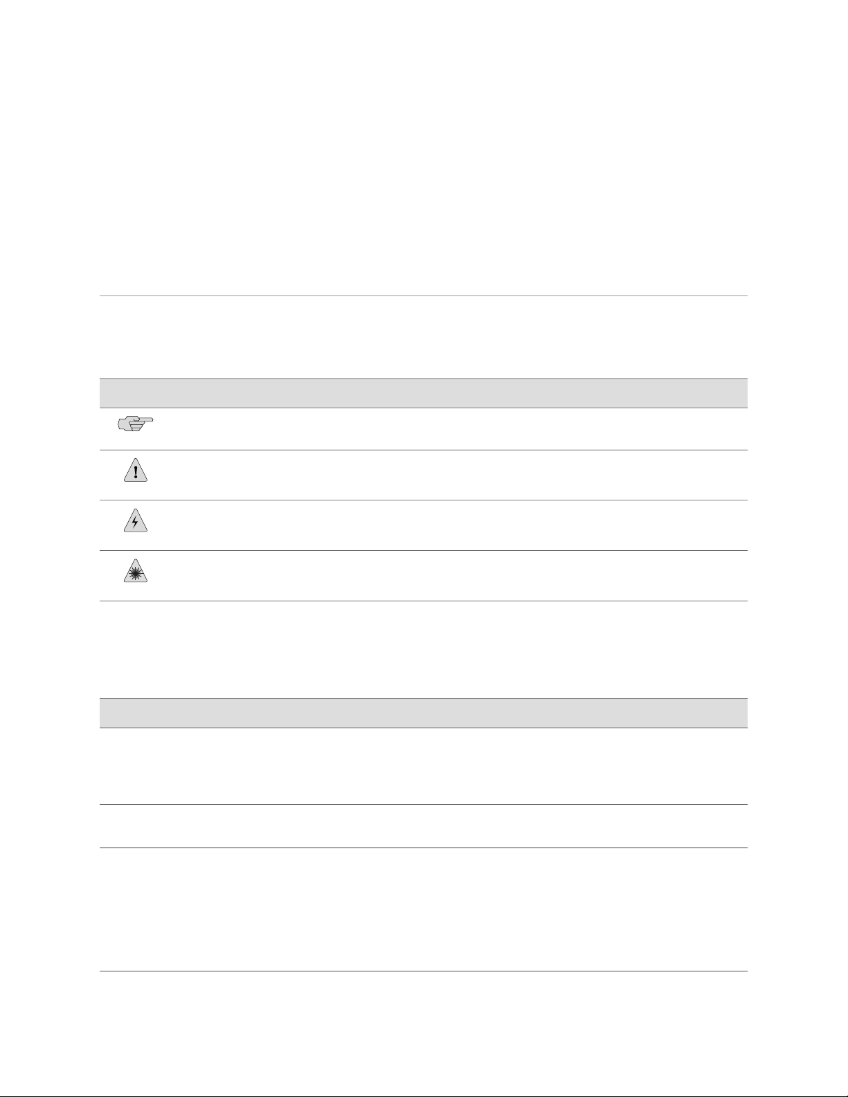
Table 2 on page xvii defines the notice icons used in this guide.
Table 2: Notice Icons
About This Guide
DescriptionMeaningIcon
Indicates important features or instructions.Informational note
Table 3 on page xvii defines the text and syntax conventions used in this guide.
Table 3: Text and Syntax Conventions
Bold sans serif typeface
Fixed-width typeface
Italic typeface
Indicates a situation that might result in loss of data or hardware damage.Caution
Alerts you to the risk of personal injury or death.Warning
Alerts you to the risk of personal injury from a laser.Laser warning
Represents text that you type.
Represents output that appears on the
terminal screen.
Introduces important new terms.
■
Identifies book names.
■
Identifies RFC and Internet draft
■
titles.
ExamplesDescriptionConvention
To enter configuration mode, type the
configure command:
user@host> configure
user@host> show chassis alarms
No alarms currently active
A policy term is a named structure
■
that defines match conditions and
actions.
JUNOS System Basics Configuration
■
Guide
RFC 1997, BGP Communities
■
Attribute
Document Conventions ■ xvii
Page 18

J2320, J2350, J4350, and J6350 Services Router Getting Started Guide
Table 3: Text and Syntax Conventions (continued)
ExamplesDescriptionConvention
Italic sans serif typeface
Sans serif typeface
| (pipe symbol)
# (pound sign)
[ ] (square brackets)
Indention and braces ( { } )
; (semicolon)
Represents variables (options for which
you substitute a value) in commands or
configuration statements.
Represents names of configuration
statements, commands, files, and
directories; IP addresses; configuration
hierarchy levels; or labels on routing
platform components.
Enclose optional keywords or variables.< > (angle brackets)
Indicates a choice between the mutually
exclusive keywords or variables on either
side of the symbol. The set of choices is
often enclosed in parentheses for clarity.
Indicates a comment specified on the
same line as the configuration statement
to which it applies.
Enclose a variable for which you can
substitute one or more values.
Identify a level in the configuration
hierarchy.
Identifies a leaf statement at a
configuration hierarchy level.
Configure the machine’s domain name:
[edit]
root@# set system domain-name
domain-name
To configure a stub area, include
■
the stub statement at the [edit
protocols ospf area area-id]
hierarchy level.
The console port is labeled
■
CONSOLE.
stub <default-metric metric>;
broadcast | multicast
(string1 | string2 | string3)
rsvp { # Required for dynamic MPLS only
community name members [
community-ids ]
[edit]
routing-options {
static {
route default {
nexthop address;
retain;
}
}
}
J-Web GUI Conventions
Bold typeface
Represents J-Web graphical user
interface (GUI) items you click or select.
> (bold right angle bracket)
Separates levels in a hierarchy of J-Web
selections.
Related Juniper Networks Documentation
J-series Services Routers are documented in multiple guides. Although the J-series
guides provide instructions for configuring and managing a Services Router with the
JUNOS CLI, they are not a comprehensive JUNOS software resource. For complete
xviii ■ Related Juniper Networks Documentation
In the Logical Interfaces box, select
■
All Interfaces.
To cancel the configuration, click
■
Cancel.
In the configuration editor hierarchy,
select Protocols>Ospf.
Page 19

documentation of the statements and commands described in J-series guides, see
the JUNOS software manuals listed in Table 4 on page xix.
Table 4: J-series Guides and Related JUNOS Software Publications
Corresponding JUNOS Software ManualChapter in a J-series Guide
Getting Started Guide for Your Router
“Services Router User Interface Overview”
“Establishing Basic Connectivity”
J-series Services Router Basic LAN and WAN Access Configuration Guide
“Using Services Router Configuration Tools”
JUNOS CLI User Guide
■
JUNOS System Basics Configuration Guide
■
JUNOS CLI User Guide
■
JUNOS System Basics Configuration Guide
■
About This Guide
“Interfaces Overview”
“Configuring DS1, DS3, Ethernet, and Serial Interfaces”
“Configuring Channelized T1/E1/ISDN PRI Interfaces”
“Configuring Digital Subscriber Line Interfaces
“Configuring Point-to-Point Protocol over Ethernet”
“Configuring ISDN”
“Configuring Link Services Interfaces”
“Configuring VoIP”
“Configuring uPIMs as Ethernet Switches”
“Routing Overview”
“Configuring Static Routes”
“Configuring a RIP Network”
JUNOS Network Interfaces Configuration Guide
■
JUNOS Interfaces Command Reference
■
JUNOS Services Interfaces Configuration Guide
■
JUNOS System Basics and Services Command Reference
■
JUNOS Network Interfaces Configuration Guide
■
JUNOS Interfaces Command Reference
■
JUNOS Network Interfaces Configuration Guide
■
JUNOS System Basics Configuration Guide
■
JUNOS System Basics and Services Command Reference
■
JUNOS Routing Protocols Configuration Guide
■
JUNOS Routing Protocols and Policies Command Reference
■
“Configuring an OSPF Network”
“Configuring the IS-IS Protocol”
“Configuring BGP Sessions”
J-series Services Router Advanced WAN Access Configuration Guide
Related Juniper Networks Documentation ■ xix
Page 20

J2320, J2350, J4350, and J6350 Services Router Getting Started Guide
Table 4: J-series Guides and Related JUNOS Software Publications (continued)
Corresponding JUNOS Software ManualChapter in a J-series Guide
“Multiprotocol Label Switching Overview”
“Configuring Signaling Protocols for Traffic Engineering”
“Configuring Virtual Private Networks”
“Configuring CLNS VPNs”
“Configuring IPSec for Secure Packet Exchange”
“Multicast Overview”
“Configuring a Multicast Network”
“Configuring Data Link Switching”
“Policy Framework Overview”
“Configuring Routing Policies”
“Configuring NAT”
“Configuring Stateful Firewall Filters and NAT”
“Configuring Stateless Firewall Filters”
JUNOS MPLS Applications Configuration Guide
■
JUNOS Routing Protocols and Policies Command Reference
■
JUNOS VPNs Configuration Guide
■
JUNOS System Basics Configuration Guide
■
JUNOS Services Interfaces Configuration Guide
■
JUNOS System Basics and Services Command Reference
■
JUNOS Multicast Protocols Configuration Guide
■
JUNOS Routing Protocols and Policies Command Reference
■
JUNOS Services Interfaces Configuration Guide
■
JUNOS System Basics and Services Command Reference
■
JUNOS Policy Framework Configuration Guide
■
JUNOS Routing Protocols and Policies Command Reference
■
JUNOS Network Interfaces Configuration Guide
■
JUNOS Policy Framework Configuration Guide
■
JUNOS Services Interfaces Configuration Guide
■
Secure Configuration Guide for Common Criteria and
■
JUNOS-FIPS
JUNOS System Basics and Services Command Reference
■
JUNOS Routing Protocols and Policies Command Reference
■
“Class-of-Service Overview”
“Configuring Class of Service”
J-series Services Router Administration Guide
“Managing User Authentication and Access”
“Configuring Autoinstallation”
xx ■ Related Juniper Networks Documentation
JUNOS Class of Service Configuration Guide
■
JUNOS System Basics and Services Command Reference
■
JUNOS System Basics Configuration Guide
■
Secure Configuration Guide for Common Criteria and
■
JUNOS-FIPS
JUNOS Network Management Configuration Guide“Configuring SNMP for Network Management”
JUNOS System Basics Configuration Guide“Configuring the Router as a DHCP Server”
JUNOS Configuration and Diagnostic Automation Guide“Automating Network Operations and Troubleshooting”
Page 21

Table 4: J-series Guides and Related JUNOS Software Publications (continued)
Corresponding JUNOS Software ManualChapter in a J-series Guide
About This Guide
“Monitoring the Router and Routing Operations”
“Monitoring Events and Managing System Log Files”
“Using Services Router Diagnostic Tools”
Documentation Feedback
We encourage you to provide feedback, comments, and suggestions so that we can
improve the documentation. You can send your comments to
techpubs-comments@juniper.net, or fill out the documentation feedback form at
http://www.juniper.net/techpubs/docbug/docbugreport.html. If you are using e-mail, be sure
to include the following information with your comments:
JUNOS System Basics and Services Command Reference
■
JUNOS Interfaces Command Reference
■
JUNOS Routing Protocols and Policies Command Reference
■
JUNOS System Log Messages Reference
■
Secure Configuration Guide for Common Criteria and
■
JUNOS-FIPS
JUNOS System Basics Configuration Guide“Configuring and Monitoring Alarms”
JUNOS Software Installation and Upgrade Guide“Performing Software Upgrades and Reboots”
JUNOS System Basics and Services Command Reference
■
JUNOS Interfaces Command Reference
■
JUNOS Routing Protocols and Policies Command Reference
■
JUNOS Services Interfaces Configuration Guide“Configuring Packet Capture”
JUNOS System Basics and Services Command Reference“Configuring RPM Probes”
Requesting Support
■ Document name
■ Document part number
■ Page number
■ Software release version
For technical support, open a support case with the Case Manager link at
http://www.juniper.net/support/ or call 1-888-314-JTAC (from the United States, Canada,
or Mexico) or 1-408-745-9500 (from elsewhere).
Documentation Feedback ■ xxi
Page 22

J2320, J2350, J4350, and J6350 Services Router Getting Started Guide
xxii ■ Requesting Support
Page 23

Part 1
J-series Overview
■ Overview of Services Routers on page 3
■ System Overview on page 13
■ PIM and VoIP Module Overview on page 43
■ Services Router User Interface Overview on page 79
J-series Overview ■ 1
Page 24

J2320, J2350, J4350, and J6350 Services Router Getting Started Guide
2 ■ J-series Overview
Page 25

Chapter 1
Overview of Services Routers
J-series Services Routers provide stable, reliable, and efficient IP routing, WAN and
LAN connectivity, and management services for small to medium-sized enterprise
networks. Services Routers typically connect small, branch, or regional offices to a
central site router, and link Internet service provider (ISP) networks.
All J-series Services Routers run the JUNOS Internet software, which offers many
advanced routing and security services. For more information about software features,
see “J-series Software Features and Licenses” on page 7. A single, common JUNOS
code base simplifies deployment, patches, and software upgrades.
You can use two user interfaces to monitor, configure, troubleshoot, and manage a
Services Router:
■ J-Web interface—A Web-based graphical interface that allows you to operate a
router without commands. The J-Web interface provides access to all JUNOS
functionality and features. Quick Configuration wizards simplify basic
configuration and minimize the risk of operator error.
■ JUNOS command-line interface—A Juniper Networks command shell that runs
on top of a UNIX-based operating system kernel. The CLI is a straightforward
command interface. On a single line, you type commands that are executed
when you press the Enter key. The CLI provides command Help and command
completion.
For an introduction to the J-Web and CLI interfaces, see “Services Router User
Interface Overview” on page 79. For more information, see the J-Web Interface User
Guide and the JUNOS CLI User Guide.
This chapter contains the following topics:
■ J2320 Services Router Overview on page 4
■ J2350 Services Router Overview on page 4
■ J4350 Services Router Overview on page 5
■ J6350 Services Router Overview on page 6
■ J-series Software Features and Licenses on page 7
■ 3
Page 26

J2320, J2350, J4350, and J6350 Services Router Getting Started Guide
J2320 Services Router Overview
The J2320 Services Router is primarily designed for remote or branch offices. It has
a small chassis that is 1 U (rack unit) in size with a nonredundant AC power supply,
an external compact flash and two universal serial bus (USB) ports for external storage,
and an optional Crypto Accelerator Module.
J2320 routers ordered with the optional Crypto Accelerator Module come standard
with 1 GB of memory, while those ordered without the Crypto Accelerator Module
come standard with 256 MB of memory. The memory on J2320 routers can be
upgraded to 1 GB. For instructions on upgrading memory, see “Replacing DRAM
Modules” on page 190.
Each J2320 chassis contains four built-in Gigabit Ethernet ports with link speeds of
10/100/1000 Mbps over a copper interface. The chassis also contains three slots for
field-replaceable Physical Interface Modules (PIMs) and Avaya voice over IP (VoIP)
modules providing flexible WAN and voice connectivity options.
The J2320 Services Router supports the following field-replaceable PIMs and Avaya
VoIP modules:
■ Gigabit Ethernet uPIM (1-port, 6-port, 8-port, and 16-port)
■ Dual-Port Serial PIM
■ Dual-Port E1 PIM
■ Dual-Port T1 PIM
■ Dual-Port Channelized T1/E1/ISDN PRI PIM
■ 4-port ISDN BRI S/T or U PIM
■ ADSL 2/2+ Annex A PIM (1 port)
■ ADSL 2/2+ Annex B PIM (1 port)
■ G.SHDSL PIM (2 ports)
■ TGM550 Telephony Gateway Module
■ TIM510 E1/T1 Telephony Interface Module (1 port)
■ TIM514 Analog Telephony Interface Module (4 ports)
■ TIM521 BRI Telephony Interface Module (4 ports)
J2350 Services Router Overview
The J2350 Services Router is primarily designed for regional or branch offices. It has
a chassis that is 1.5 U (rack unit) in size with a nonredundant AC or DC power supply,
an external compact flash and two universal serial bus (USB) ports for external storage,
and an optional Crypto Accelerator Module.
J2350 routers ordered with the optional Crypto Accelerator Module come standard
with 1 GB of memory, while those ordered without the Crypto Accelerator Module
come standard with 256 MB of memory. The memory on J2350 routers can be
4 ■ J2320 Services Router Overview
Page 27

Chapter 1: Overview of Services Routers
upgraded to 1 GB. For instructions on upgrading memory, see “Replacing DRAM
Modules” on page 190.
Each J2350 chassis contains four built-in Gigabit Ethernet ports with link speeds of
10/100/1000 Mbps over a copper interface. The chassis also contains five slots for
field-replaceable Physical Interface Modules (PIMs) and Avaya VoIP modules providing
flexible WAN and voice connectivity options.
The J2350 Services Router supports the following field-replaceable PIMs and Avaya
VoIP modules:
■ Gigabit Ethernet uPIM (1–port, 6-port, 8-port, and 16-port)
■ Dual-Port Serial PIM
■ Dual-Port E1 PIM
■ Dual-Port T1 PIM
■ Dual-Port Channelized T1/E1/ISDN PRI PIM
■ 4-port ISDN BRI S/T or U PIM
■ ADSL 2/2+ Annex A PIM (1 port)
■ ADSL 2/2+ Annex B PIM (1 port)
■ G.SHDSL PIM (2 ports)
■ TGM550 Telephony Gateway Module
■ TIM510 E1/T1 Telephony Interface Module (1 port)
■ TIM514 Analog Telephony Interface Module (4 ports)
■ TIM521 ISDN BRI Telephony Interface Module (4 ports)
J4350 Services Router Overview
The J4350 Services Router is designed primarily for regional or branch offices. It has
a chassis that is 2 U (rack units) in size with a nonredundant AC or DC power supply,
and a universal serial bus (USB) port for external storage.
J4350 routers ordered with the optional Crypto Accelerator Module come standard
with 1 GB of memory, while those ordered without the Crypto Accelerator Module
come standard with 256 MB of memory. J4350 routers can contain between 256
MB and 2 GB of memory. For instructions on adding memory, see “Replacing DRAM
Modules” on page 190.
Each J4350 chassis contains four built-in Gigabit Ethernet ports with link speeds of
10/100/1000 Mbps over a copper interface, and six slots for field-replaceable Physical
Interface Modules (PIMs) and Avaya VoIP modules. Two of the six slots (slots 3 and
6) support high-speed interfaces (ePIMs).
The J4350 Services Router supports the following field-replaceable PIMs and Avaya
VoIP modules:
J4350 Services Router Overview ■ 5
Page 28

J2320, J2350, J4350, and J6350 Services Router Getting Started Guide
■ Gigabit Ethernet uPIM (1-port, 6-port, 8-port, and 16-port)
■ SFP Gigabit Ethernet ePIM (1 port)
■ Copper Gigabit Ethernet ePIM (1 port)
■ Dual-Port Serial PIM
■ Dual-Port E1 PIM
■ Dual-Port T1 PIM
■ Dual-Port Channelized T1/E1/ISDN PRI PIM
■ E3 PIM (1 port)
■ DS3 (T3) PIM (1 port)
■ Dual-Port Fast Ethernet PIM
■ 4-port Fast Ethernet ePIM
■ 4-port ISDN BRI S/T or U PIM
■ ADSL 2/2+ Annex A PIM (1 port)
■ ADSL 2/2+ Annex B PIM (1 port)
■ G.SHDSL PIM (2 ports)
■ TGM550 Telephony Gateway Module
■ TIM510 E1/T1 Telephony Interface Module (1 port)
■ TIM514 Analog Telephony Interface Module (4 ports)
■ TIM521 ISDN BRI Telephony Interface Module (4 ports)
J6350 Services Router Overview
The J6350 Services Router is designed primarily for regional or central offices. It has
a chassis that is 2 U (rack units) in size with an optional redundant AC or DC power
supply, up to 2 GB of memory, and two universal serial bus (USB) ports for external
storage. The J6350 Services Router is a higher-performance system than the J4350
Services Router.
J6350 routers come standard with 1 GB of memory and can be upgraded to 2 GB of
memory. For instructions on adding memory, see “Replacing DRAM
Modules” on page 190.
Each J6350 chassis contains four built-in Gigabit Ethernet ports with link speeds of
10/100/1000 Mbps over a copper interface, and six slots for field-replaceable Physical
Interface Modules (PIMs) and Avaya VoIP modules. Four of the six slots (slots 2, 3,
5, and 6) support high-speed interfaces (ePIMs).
The J6350 Services Router supports the following field-replaceable PIMs and Avaya
VoIP modules:
■ Gigabit Ethernet uPIM (1–port, 6-port, 8-port, and 16-port)
■ SFP Gigabit Ethernet ePIM (1 port)
6 ■ J6350 Services Router Overview
Page 29

■ Copper Gigabit Ethernet ePIM (1 port)
■ ADSL 2/2+ Annex A PIM (1 port)
■ ADSL 2/2+ Annex B PIM (1 port)
■ Dual-Port E1 PIM
■ E3 PIM (1 port)
■ DS3 (T3) PIM (1 port)
■ Dual-Port Fast Ethernet PIM
■ Dual-Port Channelized T1/E1/ISDN PRI PIM
■ 4-port Fast Ethernet ePIM
■ G.SHDSL PIM (2 ports)
■ 4-port ISDN BRI S/T or U PIM
■ Dual-Port Serial PIM
Chapter 1: Overview of Services Routers
■ Dual-Port T1 PIM
■ TGM550 Telephony Gateway Module
■ TIM510 E1/T1 Telephony Interface Module (1 port)
■ TIM514 Analog Telephony Interface Module (4 ports)
■ TIM521 ISDN BRI Telephony Interface Module (4 ports)
J-series Software Features and Licenses
J-series Services Routers provide the software features listed in Table 5 on page 7.
You must purchase a separate software license to obtain some software features.
For more information about licenses, see “Installing and Managing J-series
Licenses” on page 161.
Table 5: Summary of J-series Features and License Requirements
Internet Protocols
IPv4
IPv6 routing and forwarding
Separate LicenseJ-series FeatureFeature Category
J-series Software Features and Licenses ■ 7
Page 30

J2320, J2350, J4350, and J6350 Services Router Getting Started Guide
Table 5: Summary of J-series Features and License Requirements (continued)
Separate LicenseJ-series FeatureFeature Category
Routing and
Multicast
Open Shortest Path First (OSPF)
Border Gateway Protocol (BGP)
Routing Information Protocol version 1 (RIPv1) and RIPv2
Static routes
Intermediate System-to-Intermediate System (IS-IS)
Connectionless Network Services (CLNS):
End system-to-Intermediate system (ES-IS) protocol
■
IS-IS extensions
■
BGP extensions
■
Static routes
■
Multiprotocol Label Switching (MPLS):
Layer 2 and Layer 3 virtual private networks (VPNs)
■
VPN routing and forwarding (VRF) table labels
■
Traffic engineering protocols:
■
Label Distribution Protocol (LDP)
■
Resource Reservation Protocol (RSVP)
■
License required for
advanced BGP (route
reflectors)
IP Address
Management
Multicast:
Internet Group Management Protocol (IGMP)
■
Protocol Independent Multicast (PIM)
■
Distance Vector Multicast Routing Protocol (DVMRP)
■
Single-source multicast
■
Static addresses
Dynamic Host Configuration Protocol (DHCP)
8 ■ J-series Software Features and Licenses
Page 31

Table 5: Summary of J-series Features and License Requirements (continued)
Chapter 1: Overview of Services Routers
Separate LicenseJ-series FeatureFeature Category
Encapsulation
Ethernet:
Media access control (MAC) encapsulation
■
802.1p tagging
■
Point-to-Point Protocol over Ethernet (PPPoE)
■
Asynchronous Transfer Mode (ATM) for asymmetric digital subscriber
■
line (ADSL) or symmetric high-speed digital subscriber line (SHDSL)
Circuit cross-connect (CCC)
■
Translational cross-connect (TCC)
■
Synchronous Point-to-Point Protocol (PPP)
Frame Relay
High-level Data Link Control (HDLC)
Serial encapsulation over RS-232, RS-449, X.21, V.35, and EIA-530
connections
802.1Q filtering and forwarding
Multilink Frame Relay
Multilink PPP
License requiredData link switching (DLSw)
Traffic Management
Ethernet Switching
Policing and shaping
Class-based queuing with prioritization
Weighted random early detection (WRED)
Queuing by virtual LAN (VLAN), data link connection identifier (DLCI),
interface, or bundle
Access switching provided by multiport Gigabit Ethernet uPIMs
J-series Software Features and Licenses ■ 9
Page 32

J2320, J2350, J4350, and J6350 Services Router Getting Started Guide
Table 5: Summary of J-series Features and License Requirements (continued)
Separate LicenseJ-series FeatureFeature Category
Security
Voice Support
High Availability
Common Criteria
Network attack detection
Denial-of-service (DoS) and distributed DoS protection
Generic routing encapsulation (GRE), IP-over-IP, and IP Security (IPSec) tunnels
Advanced Encryption Standard (AES) 128-, 192-, and 256-bit.
56-bit Data Encryption Standard (DES) and 168-bit 3DES encryption
MD5 and Secure Hash Algorithm (SHA-1) authentication
Replay attack prevention
Stateful firewall packet filters
Network Address Translation (NAT)
Compressed Real-Time Transport Protocol (CRTP)
J2320, J2350, J4350, and J6350 Services Routers support voice over IP (VoIP)
routing with the Avaya IG550 Integrated Gateway, which consists of modules
that can be installed in the PIM slots.
Virtual Router Redundancy Protocol (VRRP)
System Management
Traffic Analysis
Graceful restart according to IETF standards
Redundant interfaces
JUNOScope network manager
J-Web browser interface—for Services Router configuration and management
JUNOScript XML application programming interface (API)
JUNOS command-line interface (CLI)—for Services Router configuration and
management through the console, Telnet, SSH, or J-Web CLI terminal
Simple Network Management Protocol version 1 (SNMPv1) and SNMPv2
J-Flow flow monitoring and accounting
Packet capture (PCAP)
Real-time performance monitoring (RPM)
License required for
J-Flow
10 ■ J-series Software Features and Licenses
Page 33

Table 5: Summary of J-series Features and License Requirements (continued)
Chapter 1: Overview of Services Routers
Separate LicenseJ-series FeatureFeature Category
Activity Logging and
Monitoring
Administration
System log
J-Web event viewer
Traceroute
Supports the following external administrator databases:
RADIUS
■
TACACS+
■
Autoinstallation
Configuration rollback
Button-operated configuration rescue (CONFIG)
Confirmation of configuration changes
Software upgrades
Supports the following features for automating network operations and
troubleshooting:
Commit scripts
■
Operation scripts
■
Event policies
■
J-series Software Features and Licenses ■ 11
Page 34

J2320, J2350, J4350, and J6350 Services Router Getting Started Guide
12 ■ J-series Software Features and Licenses
Page 35

Chapter 2
System Overview
J-series J2320, J2350, J4350, and J6350 Services Routers have chassis that are similar
but with important differences. J2320, J2350, and J4350 routers have a single
nonredundant power supply and an optional Crypto Accelerator Module. J6350
routers have redundant power supplies and a standard Crypto Accelerator Module.
For field-replaceable PIMs and Avaya VoIP modules, the J2320 has three slots, the
J2350 has five slots, and the J4350 and J6350 have six slots. Of the six slots, two on
the J4350 and four on the J6350 are enhanced (high-speed) slots.
All J-series routers run the JUNOS Internet software.
This chapter contains the following topics:
■ J2320 and J2350 Services Router Hardware Features on page 13
■ J4350 and J6350 Services Router Hardware Features on page 26
■ Software Overview on page 39
J2320 and J2350 Services Router Hardware Features
This section contains the following topics:
■ J2320 and J2350 Chassis on page 14
■ J2320 and J2350 Midplane on page 18
■ J2320 and J2350 Routing Engine Hardware on page 18
■ J2320 and J2350 Boot Devices on page 19
■ J2320 and J2350 Front Panel on page 19
■ J2320 and J2350 External Compact Flashes on page 24
■ J2320 Power System on page 24
■ J2350 Power System on page 24
■ J2320 and J2350 Cooling System on page 25
J2320 and J2350 Services Router Hardware Features ■ 13
Page 36

J2320, J2350, J4350, and J6350 Services Router Getting Started Guide
J2320 and J2350 Chassis
The J2320 and J2350 chassis is a rigid sheet metal structure that houses all the other
router components (see Figure 1 on page 14 through Figure 7 on page 17). The
chassis can be installed in many types of racks or cabinets. For information about
acceptable rack types, see “Rack Requirements” on page 102.
In addition to the components described in subsequent sections, the chassis includes
the following components:
■ Mounting brackets—One pair of metal brackets can be mounted at the front or
center of the chassis for mounting the chassis in a rack or cabinet.
■ Earthing terminal—A protective earthing terminal and a PEM nut at the rear of
the chassis ensure safe dissipation of static electricity in all situations.
■ ESD point—One electrostatic discharge (ESD) point, a banana plug receptacle at
the front of the chassis, minimizes the risk of electrical discharge in potentially
hazardous environments.
CAUTION: Before removing or installing components of a functioning router, attach
an ESD strap to an ESD point and place the other end of the strap around your bare
wrist. Failure to use an ESD strap could result in damage to the router.
The router must be connected to earth ground during normal operation. The protective
earthing terminal on the rear of the chassis is provided to connect the router to
ground (see Figure 3 on page 15). Additional grounding is provided to an AC-powered
router when you plug its power supply into a grounded AC power receptacle.
For additional safety information, see “Safety and Regulatory Compliance
Information” on page 245.
Figure 1: Front of J2320 Chassis
14 ■ J2320 and J2350 Services Router Hardware Features
Page 37

Figure 2: Front of J2350 Chassis
Figure 3: Rear of J2320 Chassis
Chapter 2: System Overview
Figure 4: Rear of J2350 AC-Powered Chassis
J2320 and J2350 Services Router Hardware Features ■ 15
Page 38

J2320, J2350, J4350, and J6350 Services Router Getting Started Guide
Figure 5: Rear of J2350 DC-Powered Chassis
Figure 6: J2320 Hardware Components
16 ■ J2320 and J2350 Services Router Hardware Features
Page 39

Figure 7: J2350 Hardware Components
Chapter 2: System Overview
Table 6 on page 17 summarizes the physical specifications for the router chassis.
Table 6: J2320 and J2350 Physical Specifications
ValueDescription
Chassis dimensions
Router weight
J2320 Services Router
■
1.75 in. (4.45 cm) high
■
17.51 in. (44.48 cm) wide—18.9 in. (48.01 cm) wide with mounting brackets attached
■
15.1 in. (38.35 cm) deep—plus 0.78 in. (1.98 cm) of hardware that protrudes from the
■
chassis front
J2350 Services Router
■
2.61 in. (6.63 cm) high
■
17.51 in. (44.48 cm) wide—18.9 in. (48.01 cm) wide with mounting brackets attached
■
15.1 in. (38.35 cm) deep—plus 0.78 in. (1.98 cm) of hardware that protrudes from the
■
chassis front
J2320 Services Router
■
Minimum (no PIMs): 14.8 lbs (6.7 kg)
■
Maximum (three PIMs): 15.9 lbs (7.2 kg)
■
J2350 Services Router
■
Minimum (no PIMs): 16.3 lbs (7.4 kg)
■
Maximum (five PIMs): 18.2 lbs (8.3 kg)
■
J2320 and J2350 Services Router Hardware Features ■ 17
Page 40

J2320, J2350, J4350, and J6350 Services Router Getting Started Guide
J2320 and J2350 Midplane
The J2320 and J2350 midplane is located in the center of the chassis and forms the
rear of the PIM card cage (see Figure 6 on page 16 and Figure 7 on page 17). You
install the PIMs into the midplane from the front of the chassis. Data packets are
transferred across the midplane from the PIM to the Routing Engine, and from the
Routing Engine across the midplane to the destination PIM.
A time-division multiplexing (TDM) bus in J2320 and J2350 routers provides support
for the Avaya VoIP module TGM550. The TGM550 converts the voice path from the
TDM bus to compressed or uncompressed and packetized VoIP on an Ethernet
connection. For more information, see “PIM and VoIP Module Overview” on page 43.
J2320 and J2350 Routing Engine Hardware
The Routing Engine consists of the following components. For more information,
see “Software Overview” on page 39.
■ Processor—Creates the packet forwarding switch fabric for the router and runs
JUNOS Internet software to maintain the router's routing tables and routing
protocols.
■ DRAM—Buffers incoming packets and provides storage for the routing and
forwarding tables and for other Routing Engine processes.
To view the amount of DRAM installed on your router, issue the show chassis
routing-engine command.
■ EPROM—Stores the serial number of the Routing Engine.
To view the serial number of the Routing Engine, issue either the show chassis
routing-engine command or the show chassis hardware command.
■ Crypto Accelerator Module—Processor card that enhances performance of
cryptographic algorithms used in IP security (IPSec) services. The cryptographic
algorithms supported include Advanced Encryption Standard (AES), Data
Encryption Standard (DES), triple DES (3DES), Hashed Message Authentication
Code-Message Digest 5 (HMAC-MD5), and HMAC-Secure Hash Algorithm 1
(SHA-1). The Crypto Module is an optional feature of J2320 and J2350 Services
Routers.
To determine whether there is a Crypto Accelerator Module installed on your
router, issue the show chassis hardware command.
■ Compact flash—Provides primary storage for software images, configuration
files, and microcode. J-series routers have a primary or internal compact flash
located on the system board. For information about replacing the internal
compact flash, see “Replacing Internal Compact Flashes on J2320 and J2350
Routers” on page 180.
J2320 and J2350 Services Routers also provide a slot in the rear of the chassis
into which you can insert an additional external compact flash. For information
about external compact flashes, see “J2320 and J2350 External Compact
Flashes” on page 24.
18 ■ J2320 and J2350 Services Router Hardware Features
Page 41

J2320 and J2350 Boot Devices
J2320 and J2350 Services Routers can boot from three devices:
■ Internal compact flash
■ External compact flash (also known as the removable compact flash)
■ USB storage device
Normally, a J2320 or J2350 Services Router boots from the internal compact flash.
If the internal compact flash fails, the router attempts to boot from the external
compact flash if it is installed. If the external compact flash is not present or fails,
the router attempts to boot from the USB storage device.
J2320 and J2350 Front Panel
The front panel of a J2320 or J2350 Services Router (see Figure 8 on page 19 and
Figure 9 on page 19) allows you to install or remove PIMs, view router status LEDs,
access the console port, and perform simple control functions.
Chapter 2: System Overview
Figure 8: Front of J2320 Chassis
Figure 9: Front of J2350 Chassis
The components of the front panel, are described in the following sections:
■ Physical Interface Modules (PIMs) on page 20
■ Power Button and POWER LED on page 20
J2320 and J2350 Services Router Hardware Features ■ 19
Page 42

J2320, J2350, J4350, and J6350 Services Router Getting Started Guide
■ STATUS LED on page 21
■ ALARM LED on page 21
■ HA LED on page 22
■ RESET CONFIG Button on page 22
■ Built-In Gigabit Ethernet Ports on page 23
■ Console Port on page 23
■ AUX Port on page 23
■ USB Port on page 24
Physical Interface Modules (PIMs)
Physical Interface Modules (PIMs) provide the physical connection to various network
media types. For information about individual PIMs, see “Field-Replaceable
PIMs” on page 46.
For pinouts of PIM cable connectors, see “Network Cable Specifications and Connector
Pinouts” on page 225. For PIM replacement instructions, see “Replacing a
PIM” on page 174.
The J2320 front panel has three slots and the J2350 front panel has five slots for
field-replaceable PIMs. These slots are numbered from top to bottom and from left
to right as shown in Figure 10 on page 20.
Slot 0 is a fixed interface module that contains four built-in Gigabit Ethernet ports.
For more information, see “Built-In Gigabit Ethernet Ports” on page 23.
Figure 10: Slot Number Diagram on J2320 and J2350
Power Button and POWER LED
The power button is located on the left side of the front panel (see
Figure 1 on page 14). You can use the power button to power the Services Router
on and off. When you power on the router, the Routing Engine boots as the power
supply completes its startup sequence.
The POWER LED is located to the upper left of the LED dashboard. Table 7 on page
21 describes the POWER LED.
20 ■ J2320 and J2350 Services Router Hardware Features
Page 43

Table 7: J2320 and J2350 POWER LED
Chapter 2: System Overview
DescriptionStateColor
Power is functioning correctly.On steadilyGreen
Blinking
After the router is powered on, status indicators—such as LEDs on the front panel
and show chassis command output—can take up to 60 seconds to indicate that the
power supply is functioning normally. Ignore error indicators that appear during the
first 60 seconds.
If you need to power off the router after the Routing Engine finishes booting, use the
J-Web interface or the CLI to halt the Services Router first. For instructions, see the
J-series Services Router Administration Guide. Alternatively, you can press and release
the power button to gracefully shut down the router. For more information, see
“Powering a Services Router On and Off” on page 127.
STATUS LED
When the system is powered on, the STATUS LED changes from off to blinking green.
Startup takes approximately 90 seconds to complete. If you want to turn the system
off and on again, we recommend waiting a few seconds between shutting it down
and powering it back up. Table 8 on page 21 describes the STATUS LED.
Table 8: J2320 and J2350 STATUS LED
Power button has been pressed and quickly released, and
the router is gracefully shutting down.
Router is not receiving power.OffUnlit
DescriptionStateColor
Router is starting up or performing diagnostics.BlinkingGreen
Router is operating normally.On steadily
Error has been detected.BlinkingRed
ALARM LED
The ALARM LED lights amber to indicate a minor condition that requires monitoring
or maintenance and lights red to indicate a major condition that can result in a system
shutdown. When the condition is corrected, the light turns off. Table 9 on page 22
describes the ALARM LED.
J2320 and J2350 Services Router Hardware Features ■ 21
Page 44

J2320, J2350, J4350, and J6350 Services Router Getting Started Guide
Table 9: J2320 and J2350 ALARM LED
On steadilyRed
DescriptionStateColor
Major alarm indicates a critical situation on the router that
has resulted from one of the following conditions. A red
alarm condition requires immediate action:
One or more hardware components have failed.
■
One or more hardware components have exceeded
■
temperature thresholds.
An alarm condition configured on an interface has
■
triggered a critical warning.
On steadilyYellow
Minor alarm condition requires monitoring or maintenance:
Indicates a noncritical condition on the router that, if
■
left unchecked, might cause an interruption in service
or degradation in performance.
A missing rescue configuration or software license
■
generates an amber system alarm.
No alarms.OffUnlit
For information about alarm conditions and corrective actions, see “Chassis Alarm
Conditions” on page 211. For additional information, see the J-series Services Router
Administration Guide.
HA LED
The HA (high availability) LED is for future use. The LED lights when the router starts,
but otherwise remains unlit.
RESET CONFIG Button
Use the RESET CONFIG button to return the router to either the rescue configuration
or the factory default configuration. The button is recessed to prevent it from being
pressed accidentally. To press this button insert a small probe (such as a straightened
paper clip) into the pinhole on the front panel (see Figure 8 on page 19 and
Figure 9 on page 19).
For example, if someone inadvertently commits a configuration that denies
management access to a Services Router, you can delete the invalid configuration
and replace it with a rescue configuration by pressing the RESET CONFIG button. You
must have previously set the rescue configuration through the J-Web interface or the
CLI. The rescue configuration is a previously committed, valid configuration.
CAUTION: Pressing and holding the RESET CONFIG button for 15 seconds or
more—until the STATUS LED blinks red—deletes all configurations on the router,
including the backup configurations and rescue configuration, and loads and commits
the factory configuration.
22 ■ J2320 and J2350 Services Router Hardware Features
Page 45

Chapter 2: System Overview
You can change the default behavior of the RESET CONFIG button. For more
information, see the J-series Services Router Basic LAN and WAN Access Configuration
Guide.
Built-In Gigabit Ethernet Ports
Four built-in Gigabit Ethernet ports provide LAN connections over copper interfaces
to hubs, switches, local servers, and workstations. You can also designate an Ethernet
port for management traffic. When configuring one of these ports, you use the
interface name that corresponds to the port’s location. From left to right on the front
panel, the interface names for the ports are ge-0/0/0, ge-0/0/1, ge-0/0/2, and
ge-0/0/3.
For Gigabit Ethernet port pinout information, see “Gigabit Ethernet uPIM RJ-45
Connector Pinout” on page 235.
Each port has two LEDs, a TX/RX LED on the left side and a LINK LED on the right
side. Table 10 on page 23 describes the built-in Ethernet port LEDs.
Table 10: Gigabit Ethernet Port LEDs
LINK
TX/RX
Console Port
You can use the console port on the chassis front panel to connect to the Routing
Engine through an RJ-45 serial cable. From the chassis console port, you can use the
CLI to configure the router. The console port is configured as data terminal equipment
(DTE) and supports the RS-232 (EIA-232) standard.
For information about securing the chassis console port, see the J-series Services
Router Administration Guide.
For pinout information, see “Chassis Console Port Pinouts” on page 236.
AUX Port
DescriptionStateColorFunction
Port is online.On steadilyGreen
Port is offline.OffUnlit
Port is transmitting or receiving data.BlinkingGreen
Port might be online, but it is not receiving data.OffUnlit
The port labeled AUX on the front panel of the J-series Services Router is for future
use and is not activated.
J2320 and J2350 Services Router Hardware Features ■ 23
Page 46

J2320, J2350, J4350, and J6350 Services Router Getting Started Guide
USB Port
The USB ports on the front panel of the router (see Figure 8 on page 19 and
Figure 9 on page 19) accept a USB storage device or USB storage device adapter with
a compact flash installed, as defined in the CompactFlash Specification published by
the CompactFlash Association. When a USB storage device is installed and configured,
it automatically acts as a secondary boot device if the internal compact flash fails on
startup. Depending on the size of the USB storage device, you can also configure it
to receive any core files generated during a failure. For information about configuring
a USB storage device, see the J-series Services Router Administration Guide.
NOTE: For a list of supported USB storage devices, see the J-series Services Router
Release Notes at http://www.juniper.net.
J2320 and J2350 External Compact Flashes
J2320 Power System
On J2320 and J2350 routers, an external compact flash, also known as removable
compact flash, accepts a type I or II compact flash, as defined in the CompactFlash
Specification published by the CompactFlash Association. The J2320 and J2350 chassis
has a slot on the rear for external compact flashes (see Figure 3 on page 15). When
the external compact flash is installed and configured, it automatically acts as the
secondary boot device if the internal compact flash fails on startup.
Depending on the capacity of the external compact flash, you can also configure it
to receive any core files generated during a failure. For information about configuring
an external compact flash, see the J-series Services Router Administration Guide.
The J2320 Services Router uses AC power (see Figure 3 on page 15). The autosensing
power supply distributes the different output voltages to the router components
according to their voltage requirements. The power supply is fixed in the chassis,
and is not field-replaceable.
The AC power supply has a single AC appliance inlet that requires a dedicated AC
power feed.
The J2320 AC-powered chassis has a power switch and does not include a power
LED.
For information about site power preparations, see “Power Guidelines, Requirements,
and Specifications” on page 105. For information about connecting the router to power
and ground, see “Connecting Power” on page 122.
J2350 Power System
The J2350 Services Router uses either AC or DC power. The autosensing power supply
(see Figure 4 on page 15 or Figure 5 on page 16) distributes the different output
voltages to the router components according to their voltage requirements. The
power supply is fixed in the chassis, and is not field-replaceable.
24 ■ J2320 and J2350 Services Router Hardware Features
Page 47

Chapter 2: System Overview
The AC power supply has a single AC appliance inlet that requires a dedicated AC
power feed. The DC power supply has a terminal block that provides a single DC
input (–48 VDC and return) and requires a dedicated 15 A (–48 VDC) circuit breaker.
The J2350 AC-powered or DC-powered chassis has a power switch and does not
include a power LED.
For information about site power preparations, see “Power Guidelines, Requirements,
and Specifications” on page 105. For information about connecting the router to power
and ground, see “Connecting Power” on page 122.
NOTE: You cannot mix DC and AC power supplies in the same chassis.
WARNING: DC-powered Services Routers are intended for installation only in a
restricted access location.
J2320 and J2350 Cooling System
The cooling system in J2320 and J2350 routers is from side to side. The J2320 router
has five cooling fans and the J2350 router has four cooling fans. The fans draw air
through vents along the left side of the chassis and exhaust it through vents on the
right side of the chassis. The airflow produced by these fans keeps router components
within the acceptable temperature range (see Figure 11 on page 26 and
Figure 12 on page 26). The speed of the fans is adjusted automatically according to
the current temperature.
On J2350 routers that comply with Network Equipment Building System (NEBS)
criteria, an air filter protects the air intake opening at the front of the chassis and
must be replaced periodically. To verify that the system is a NEBS-compliant system,
run the show chassis hardware command. A NEBS-compliant system displays the
term NEBS in the output. For instructions on how to replace air filters, see “Replacing
Air Filters on J2350 Routers” on page 207.
The Routing Engine monitors the temperature of the router components. If the
maximum temperature specification, as measured at the CPU junction, is exceeded
and the router cannot be adequately cooled, the Routing Engine shuts down the
hardware components.
J2320 and J2350 routers shut down when the CPU temperature reaches 80°C (176°F).
There is no alarm for temperature. You can view the CPU junction temperature using
the show chassis routing-engine command. The CPU temperature runs a few degrees
higher than the routing engine temperature displayed on the Monitor>Chassis page
of the J-Web interface.
An additional fan is part of each power supply. This fan is not regulated by the
operating system.
J2320 and J2350 Services Router Hardware Features ■ 25
Page 48

J2320, J2350, J4350, and J6350 Services Router Getting Started Guide
Figure 11: Airflow Through the J2320 Chassis
Figure 12: Airflow Through the J2350 Chassis
J4350 and J6350 Services Router Hardware Features
This section contains the following topics:
■ J4350 and J6350 Chassis on page 27
■ J4350 and J6350 Midplane on page 31
■ J4350 and J6350 Routing Engine Hardware on page 31
■ J4350 and J6350 Boot Devices on page 31
■ J4350 and J6350 Front Panel on page 32
26 ■ J4350 and J6350 Services Router Hardware Features
Page 49

■ J4350 Power System on page 36
■ J6350 Power System on page 37
■ J4350 and J6350 Cooling System on page 38
J4350 and J6350 Chassis
The J4350 and J6350 chassis is a rigid sheet metal structure that houses all the other
router components (see Figure 13 on page 28 through Figure 18 on page 30). The
chassis can be installed in many types of racks or cabinets. For information about
acceptable rack types, see “Rack Requirements” on page 102.
In addition to the features described in subsequent sections, the chassis includes the
following features:
■ Mounting brackets—One pair of metal brackets can be mounted at the front or
center of the chassis. Use the brackets for mounting the chassis in a rack or
cabinet.
Chapter 2: System Overview
■ Earthing terminals—Two protective earthing terminals, PEM nuts at the rear of
the chassis ensure safe dissipation of static electricity in all situations.
■ ESD point—One electrostatic discharge (ESD) point, a banana plug receptacle at
the front of the chassis, minimizes the risk of electrical discharge in potentially
hazardous environments.
CAUTION: Before removing or installing components of a functioning router, attach
an ESD strap to an ESD point and place the other end of the strap around your bare
wrist. Failure to use an ESD strap could result in damage to the router.
The router must be connected to earth ground during normal operation. The protective
earthing terminals on the rear of the chassis are provided to connect the router to
ground (see Figure 14 on page 28). Additional grounding is provided to an AC-powered
router when you plug its power supply into a grounded AC power receptacle.
For additional safety information, see “Safety and Regulatory Compliance
Information” on page 245.
J4350 and J6350 Services Router Hardware Features ■ 27
Page 50

J2320, J2350, J4350, and J6350 Services Router Getting Started Guide
Figure 13: Front of J4350 and J6350 Chassis
Figure 14: Rear of J4350 AC-Powered Chassis
NOTE: The J4350 AC-powered chassis has a power switch and does not include a
power supply LED (unlike the J6350 AC-powered chassis).
Figure 15: Rear of J6350 AC-Powered Chassis
28 ■ J4350 and J6350 Services Router Hardware Features
Page 51

Figure 16: Rear of J4350 DC-Powered Chassis
Figure 17: Rear of DC-Powered J6350 Chassis
Chapter 2: System Overview
J4350 and J6350 Services Router Hardware Features ■ 29
Page 52

J2320, J2350, J4350, and J6350 Services Router Getting Started Guide
Figure 18: J4350 and J6350 Hardware Components
Table 11 on page 30 summarizes the physical specifications for the router chassis.
Table 11: J4350 and J6350 Physical Specifications
ValueDescription
Chassis dimensions
Router weight
3.44 in. (8.74 cm) high
■
17.44 in. (44.3 cm) wide—19.44 in. (48.38 cm) wide with mounting brackets attached
■
21.13 in. (53.67 cm) deep—plus 0.5 in. (1.27 cm) of hardware that protrudes from the chassis
■
front
J4350 Services Router:
■
Minimum (no PIMs): 23 lb (10.4 kg)
■
Maximum (six PIMs): 25.3 lb (11.5 kg)
■
J6350 Services Router
■
Minimum (no PIMs and one power supply): 25.5 lb (11.6 kg)
■
Maximum (six PIMs and two power supplies): 30.7 lb (13.9 kg)
■
30 ■ J4350 and J6350 Services Router Hardware Features
Page 53

J4350 and J6350 Midplane
The midplane is located in the center of the chassis and forms the rear of the PIM
card cage (see Figure 18 on page 30). You install the PIMs into the midplane from
the front of the chassis. Data packets are transferred across the midplane from the
PIM to the Routing Engine, and from the Routing Engine across the midplane to the
destination PIM.
J4350 and J6350 Routing Engine Hardware
The Routing Engine consists of the following components. For more information,
see “Software Overview” on page 39.
■ Processor—Creates the packet forwarding switch fabric for the router and runs
JUNOS Internet software to maintain the router's routing tables and routing
protocols.
■ DRAM—Buffers incoming packets and provides storage for the routing and
forwarding tables and for other Routing Engine processes.
Chapter 2: System Overview
To view the amount of DRAM installed on your router, issue the show chassis
routing-engine command.
■ EPROM—Stores the serial number of the Routing Engine.
To view the serial number of the Routing Engine, issue either the show chassis
routing-engine command or the show chassis hardware command.
■ Crypto Accelerator Module—Processor card that enhances performance of
cryptographic algorithms used in IP security (IPSec) services. The cryptographic
algorithms supported include Advanced Encryption Standard (AES), Data
Encryption Standard (DES), triple DES (3DES), Hashed Message Authentication
Code-Message Digest 5 (HMAC-MD5), and HMAC-Secure Hash Algorithm 1
(SHA-1).
To determine whether there is a Crypto Accelerator Module installed on your
router, issue the show chassis hardware command.
■ Compact flash—Provides primary storage for software images, configuration
files, and microcode. J4350 and J6350 routers have a slot on the motherboard
for an internal compact flash. For information about replacing the compact flash,
see “Replacing Internal Compact Flashes on J4350 and J6350
Routers” on page 183.
J4350 and J6350 Boot Devices
The J4350 and J6350 Services Routers can boot from two devices:
■ Internal compact flash
■ USB storage device
Normally, the J4350 or J6350 Services Router boots from the internal compact flash.
If the compact flash fails, the router attempts to boot from the USB storage device.
J4350 and J6350 Services Router Hardware Features ■ 31
Page 54

J2320, J2350, J4350, and J6350 Services Router Getting Started Guide
J4350 and J6350 Front Panel
The front panel of the Services Router (see Figure 19 on page 32) allows you to install
or remove PIMs, view router status LEDs, access the console port, and perform simple
control functions.
Figure 19: Front of J4350 and J6350 Chassis
The components of the front panel, from left to right, are described in the following
sections:
■ Physical Interface Modules (PIMs) on page 32
■ Power Button and POWER LED on page 33
■ STATUS LED on page 34
■ ALARM LED on page 34
■ HA LED on page 35
■ RESET CONFIG Button on page 35
■ Built-In Gigabit Ethernet Ports on page 35
■ Console Port on page 36
■ AUX Port on page 36
■ USB Port on page 36
Physical Interface Modules (PIMs)
Physical Interface Modules (PIMs) provide the physical connection to various network
media types. For information about individual PIMs, see “Field-Replaceable
PIMs” on page 46.
For pinouts of PIM cable connectors, see “Network Cable Specifications and Connector
Pinouts” on page 225. For PIM replacement instructions, see “Replacing a
PIM” on page 174.
32 ■ J4350 and J6350 Services Router Hardware Features
Page 55

Chapter 2: System Overview
Each J4350 and J6350 Services Router has six front panel slots for field-replaceable
PIMs. These slots are numbered from top to bottom and from left to right as shown
in the slot number diagram on the front panel, shown in Figure 20 on page 33.
Figure 20: Slot Number Diagram on Front Panel
Gigabit Ethernet and 4-port Fast Ethernet ePIMs can be installed in high-speed slots
only. High-speed slots are indicated by a black triangle containing an E in the front
panel slot number diagram. On J4350 Services Routers, the high-speed slots are
slot 3 and slot 6. On J6350 Services Routers, the high-speed slots are slots 2, 3, 5,
and 6.
Table 12: POWER LED
Slot 0 is the fixed interface module that contains the built-in Ethernet ports.
Power Button and POWER LED
The power button is located on the left side of the front panel (see
Figure 19 on page 32). You can use the power button to power the Services Router
on and off. When you power on the router, the Routing Engine boots as the power
supply completes its startup sequence.
The POWER LED is located to the upper left of the LED dashboard. Table 12 on page
33 describes the POWER LED.
DescriptionStateColor
Power is functioning correctly.On steadilyGreen
Blinking
After the router is powered on, status indicators—such as LEDs on the front panel
and show chassis command output—can take up to 60 seconds to indicate that the
power supply is functioning normally. Ignore error indicators that appear during the
first 60 seconds.
Power button has been pressed and quickly released, and
the router is gracefully shutting down.
Router is not receiving power.OffUnlit
If you need to power off the router after the Routing Engine finishes booting, use the
J-Web interface or the CLI to halt the Services Router first. For instructions, see the
J-series Services Router Administration Guide. Alternatively, you can press and release
the power button to gracefully shut down the router. For more information, see
“Powering a Services Router On and Off” on page 127.
J4350 and J6350 Services Router Hardware Features ■ 33
Page 56

J2320, J2350, J4350, and J6350 Services Router Getting Started Guide
STATUS LED
When the system is powered on, the STATUS LED changes from off to blinking green.
Startup takes approximately 90 seconds to complete. If you want to turn the system
off and on again, we recommend waiting a few seconds between shutting it down
and powering it back up. Table 13 on page 34 describes the STATUS LED.
Table 13: STATUS LED
DescriptionStateColor
Router is starting up or performing diagnostics.BlinkingGreen
Router is operating normally.On steadily
Error has been detected.BlinkingRed
Table 14: ALARM LED
ALARM LED
The ALARM LED lights yellow to indicate a minor condition that requires monitoring
or maintenance and lights red to indicate a major condition that can result in a system
shutdown. When the condition is corrected, the light turns off. Table 14 on page 34
describes the ALARM LED.
DescriptionStateColor
On steadilyRed
On steadilyYellow
Major alarm indicates a critical situation on the router that
has resulted from one of the following conditions. A red
alarm condition requires immediate action:
One or more hardware components have failed.
■
One or more hardware components have exceeded
■
temperature thresholds.
An alarm condition configured on an interface has
■
triggered a critical warning.
Minor alarm condition requires monitoring or maintenance:
Indicates a noncritical condition on the router that, if
■
left unchecked, might cause an interruption in service
or degradation in performance.
A missing rescue configuration or software license
■
generates a yellow system alarm.
For information about alarm conditions and corrective actions, see “Chassis Alarm
Conditions” on page 211. For additional information, see the J-series Services Router
Administration Guide.
34 ■ J4350 and J6350 Services Router Hardware Features
No alarms.OffUnlit
Page 57

Chapter 2: System Overview
HA LED
The HA (high availability) LED is for future use. The LED lights when the router starts,
but otherwise remains unlit.
RESET CONFIG Button
Use the RESET CONFIG button to return the router to either the rescue configuration
or the factory default configuration. The button is recessed to prevent it from being
pressed accidentally. To press this button insert a small probe (such as a straightened
paper clip) into the pinhole on the front panel (see Figure 19 on page 32).
For example, if someone inadvertently commits a configuration that denies
management access to a Services Router, you can delete the invalid configuration
and replace it with a rescue configuration by pressing the RESET CONFIG button. You
must have previously set the rescue configuration through the J-Web interface or the
CLI. The rescue configuration is a previously committed, valid configuration.
CAUTION: Pressing and holding the RESET CONFIG button for 15 seconds or
more—until the STATUS LED blinks red—deletes all configurations on the router,
including the backup configurations and rescue configuration, and loads and commits
the factory configuration.
You can change the default behavior of the RESET CONFIG button. For more
information, see the J-series Services Router Basic LAN and WAN Access Configuration
Guide.
Built-In Gigabit Ethernet Ports
Four built-in Gigabit Ethernet ports provide LAN connections over copper interfaces
to hubs, switches, local servers, and workstations. You can also designate an Ethernet
port for management traffic. When configuring one of these ports, you use the
interface name that corresponds to the port’s location. From left to right on the front
panel, the interface names for the ports are ge-0/0/0, ge-0/0/1, ge-0/0/2, and
ge-0/0/3.
For Gigabit Ethernet port pinout information, see “Gigabit Ethernet ePIM RJ-45
Connector Pinout” on page 236.
Each port has two LEDs, a TX/RX LED on the left side and a LINK LED on the right
side. Table 15 on page 35 describes the built-in Ethernet port LEDs.
Table 15: Gigabit Ethernet Port LEDs
LINK
DescriptionStateColorFunction
Port is online.On steadilyGreen
Port is offline.OffUnlit
J4350 and J6350 Services Router Hardware Features ■ 35
Page 58

J2320, J2350, J4350, and J6350 Services Router Getting Started Guide
Table 15: Gigabit Ethernet Port LEDs (continued)
TX/RX
Console Port
You can use the console port on the chassis front panel to connect to the Routing
Engine through an RJ-45 serial cable. From the chassis console port, you can use the
CLI to configure the router. The console port is configured as data terminal equipment
(DTE) and supports the RS-232 (EIA-232) standard.
For information about securing the chassis console port, see the J-series Services
Router Administration Guide.
DescriptionStateColorFunction
Port is transmitting or receiving data.BlinkingGreen
Port might be online, but it is not receiving data.OffUnlit
J4350 Power System
For pinout information, see “Chassis Console Port Pinouts” on page 236.
AUX Port
The port labeled AUX on the front panel of the J4350 or J6350 Services Router is for
future use and is not activated.
USB Port
The USB ports on the front panel of the router (see Figure 19 on page 32) accept a
USB storage device or USB storage device adapter with a compact flash installed, as
defined in the CompactFlash Specification published by the CompactFlash Association.
When a USB storage device is installed and configured, it automatically acts as a
secondary boot device if the internal compact flash fails on startup. Depending on
the size of the USB storage device, you can also configure it to receive any core files
generated during a failure. For information about configuring a USB storage device,
see the J-series Services Router Administration Guide.
NOTE: For a list of supported USB storage devices, see the J-series Services Router
Release Notes at http://www.juniper.net.
The J4350 Services Router uses either AC or DC power. The autosensing power supply
(see Figure 14 on page 28 or Figure 16 on page 29) distributes the different output
voltages to the router components according to their voltage requirements. The
power supply is fixed in the chassis and is not field-replaceable.
The AC power supply has a single AC appliance inlet that requires a dedicated AC
power feed. The DC power supply has a terminal block that provides a single DC
input (–48 VDC and return) and requires a dedicated 15 A (–48 VDC) circuit breaker.
36 ■ J4350 and J6350 Services Router Hardware Features
Page 59

The J4350 AC-powered chassis has a power switch and does not include a power
LED.
The J4350 DC-powered chassis includes a power supply LED located to the upper
right of the power supply connector. Table 16 on page 37 describes the power supply
LED.
Table 16: Power Supply LED
DescriptionState
No power is flowing to the power supply.Off
Power supply is connected and power is flowing.Green
Power supply is connected, but the router is not powered on.Yellow
Chapter 2: System Overview
J6350 Power System
For information about site power preparations, see “Power Guidelines, Requirements,
and Specifications” on page 105. For information about connecting the router to power
and ground, see “Connecting Power” on page 122.
NOTE: You cannot mix DC and AC power supplies in the same chassis.
WARNING: DC-powered Services Routers are intended for installation only in a
restricted access location.
The J6350 Services Router uses either AC or DC power. You can install one or two
autosensing, load-sharing power supplies on the system board at the bottom of the
chassis, as shown in Figure 15 on page 28 or Figure 17 on page 29. The power
supplies distribute the different output voltages to the router components, depending
on their voltage requirements. When two power supplies are installed and operational,
they automatically share the electrical load.
For full redundancy, two power supplies are required. If a power supply stops
functioning for any reason, the second power supply instantly begins providing all
the power the router needs for normal functioning. It can provide full power
indefinitely.
Each power supply has an LED located to the upper right of the power supply
connector. Table 16 on page 37 describes the power supply LED.
For information about site power preparations, see “Power Guidelines, Requirements,
and Specifications” on page 105. For information about connecting the router to power
and ground, see “Connecting Power” on page 122.
J4350 and J6350 Services Router Hardware Features ■ 37
Page 60

J2320, J2350, J4350, and J6350 Services Router Getting Started Guide
Power supplies on J6350 Services Routers are hot-removable and hot-insertable. You
can remove and replace a redundant power supply without powering down the router
or disrupting the routing functions. To avoid electrical injury, carefully follow the
instructions in “Replacing Power System Components” on page 193.
NOTE: You cannot mix DC and AC power supplies in the same chassis.
WARNING: DC-powered Services Routers are intended for installation only in a
restricted access location.
J4350 and J6350 Cooling System
The cooling system includes three fans at the rear of the chassis. The airflow produced
by these fans keeps router components within the acceptable temperature range
(see Figure 21 on page 39). The speed of the fans is adjusted automatically according
to the current temperature.
An air filter protects the air intake opening at the front of the chassis and must be
replaced periodically. For instructions, see “Replacing Air Filters on J4350 and J6350
Routers” on page 208.
The Routing Engine monitors the temperature of the router components. If the
maximum temperature specification, as measured at the CPU junction, is exceeded
and the router cannot be adequately cooled, the Routing Engine shuts down the
hardware components.
When the CPU temperature reaches 80°C (176°F), a yellow alarm is triggered. When
the CPU temperature reaches 105°C (221°F), the system shuts down. There is no
red alarm for temperature. You can view the CPU junction temperature using the
show chassis routing-engine command. The CPU temperature runs a few degrees
higher than the routing engine temperature displayed on the Monitor>Chassis page
of the J-Web interface.
NOTE: On J4350 and J6350 routers that are not designed to comply with Network
Equipment Building System (NEBS) criteria, the temperature at which the system
shuts down is 90°C (194°F) rather than 105°C (221°F). To verify that the system is
a NEBS-compliant system, run the show chassis hardware command. A
NEBS-compliant system displays the term NEBS in the output.
An additional fan is part of each power supply. This fan is not regulated by the
operating system.
38 ■ J4350 and J6350 Services Router Hardware Features
Page 61

Figure 21: Airflow Through the J4350 and J6350 Chassis
Chapter 2: System Overview
Software Overview
Each J-series Services Router runs the JUNOS Internet software on its general-purpose
processors. Designed for the large production networks typically supported by Internet
service providers (ISPs), the JUNOS software includes processes for Internet Protocol
(IP) routing and for managing interfaces, networks, and the router chassis.
The JUNOS Internet software runs on the Routing Engine. The Routing Engine kernel
coordinates communication among the JUNOS software processes and provides a
link to the Packet Forwarding Engine.
With the J-Web interface and the command-line interface (CLI) you configure the
routing protocols that run on the Services Router and set the properties of its network
interfaces. After activating a software configuration, use either user interface to
monitor the protocol traffic passing through the router, manage operations, and
diagnose protocol and network connectivity problems.
This section contains the following topics:
■ Routing Engine and Packet Forwarding Engine on page 40
■ Kernel and Microkernel on page 40
■ JUNOS Software Processes on page 40
■ User Interfaces on page 41
Software Overview ■ 39
Page 62

J2320, J2350, J4350, and J6350 Services Router Getting Started Guide
Routing Engine and Packet Forwarding Engine
A Services Router has two primary software processing components:
■ Routing Engine—The Routing Engine provides three main functions:
■ Creates the packet forwarding switch fabric for the Services Router, providing
route lookup, filtering, and switching on incoming data packets, then directing
outbound packets to the appropriate interface for transmission to the
network.
■ Maintains the routing tables used by the router and controls the routing
protocols that run on the router.
■ Provides control and monitoring functions for the router, including controlling
power and monitoring system status.
■ Packet Forwarding Engine—Processes packets; applies filters, routing policies,
and other features; and forwards packets to the next hop along the route to their
final destination.
For information about Routing Engine hardware, see “J2320 and J2350 Routing
Engine Hardware” on page 18 and “J4350 and J6350 Routing Engine
Hardware” on page 31.
Kernel and Microkernel
The Routing Engine kernel provides the underlying infrastructure for all JUNOS
software processes by doing the following:
■ Linking the routing tables maintained by the routing protocol process with the
forwarding table maintained by the Routing Engine
■ Coordinating communication with the Packet Forwarding Engine, primarily by
synchronizing the Packet Forwarding Engine’s forwarding table with the master
forwarding table maintained by the Routing Engine
The microkernel contains device drivers and processes that the Packet Forwarding
Engine uses to govern the flow of packets through the Services Router.
JUNOS Software Processes
The JUNOS software running on the Routing Engine and Packet Forwarding Engine
consists of multiple processes that are responsible for individual Services Router
functions.
40 ■ Software Overview
The separation of functions provides operational stability, because each process
accesses its own protected memory space. In addition, because each process is a
separate software package, you can selectively upgrade all or part of the JUNOS
software, for added flexibility.
Table 17 on page 41 describes the primary JUNOS software processes.
Page 63

Table 17: JUNOS Software Processes
DescriptionNameProcess
Chapter 2: System Overview
process
process
protocol
process
process (also
called device
control
process)
mgdManagement
Manages the Services Router system as follows:
Provides communication between the other processes and an interface to the
■
configuration database
Populates the configuration database with configuration information and retrieves
■
the information when queried by other processes to ensure that the system
operates as configured
Interacts with the other processes when commands are issued through one of
■
the user interfaces on the router
chassisdChassis
Controls a Services Router chassis and its components as follows:
Detects hardware on the system that is used to configure network interfaces
■
Monitors the physical status of hardware components and field-replaceable units
■
(FRUs), detecting when environment sensors such as temperature sensors are
triggered
Relays signals and interrupts—for example, when devices are taken offline, so
■
that the system can close sessions and shut down gracefully
rpdRouting
Defines how routing protocols such as RIP, OSPF, and BGP operate on the router,
including selecting routes and maintaining fowarding tables.
dcdInterface
Supplies the programs that configure and monitor network interfaces by defining
physical characteristics such as link encapsulation, hold times, and keepalive timers.
process
fwddForwarding
User Interfaces
Responsible for most of the packet transmission through a Services Router. The overall
performance of the router is largely determined by the effectiveness of the forwarding
process.
The user interfaces on a Services Router interact with the management process to
execute commands and store and retrieve information from the configuration
database. The user interfaces operate as clients that communicate with the JUNOS
Internet software through an application programming interface (API).
The following primary user interfaces are shipped with the router:
■ J-Web graphical user interface—Includes quick configuration capabilities for
performing the minimum required steps to enable a feature, plus a built-in
configuration editor with access to the entire configuration hierarchy to fully
configure the router. The J-Web interface also provides tools for monitoring,
managing, and diagnosing router operation.
■ Command-line interface (CLI)—Grants access to the complete JUNOS command
and configuration hierarchies, to monitor the router, diagnose problems, and
configure it completely.
Software Overview ■ 41
Page 64

J2320, J2350, J4350, and J6350 Services Router Getting Started Guide
For more information, see “Services Router User Interface Overview” on page 79.
Other user interfaces for the Services Router interact with the management process
through the common API interface. These interfaces are designed to facilitate the
configuration of one or, in some cases, many routers on the network. Among the
supported interfaces are the JUNOScope and Session and Resource Control (SRC)
applications. For more information about these products, see the JUNOScope Software
User Guide and the SRC-PE Getting Started Guide.
42 ■ Software Overview
Page 65

Chapter 3
PIM and VoIP Module Overview
J-series Services Routers accept Physical Interface Modules (PIMs) and Avaya VoIP
modules in the slots on the front of the chassis.
CAUTION: PIMs and VoIP modules are not hot-swappable. You must power off the
Services Router before removing or inserting a PIM or VoIP module. Ensure that the
PIMs and VoIP modules are installed in the router chassis before booting up the
system.
A Physical Interface Module (PIM) is a network interface card that is installed on a
J-series Services Router, to provide physical connections to a LAN or a WAN. The
PIM receives incoming packets from the network and transmits outgoing packets to
the network. Each PIM is equipped with a dedicated network processor that forwards
incoming data packets to the Routing Engine, and receives outgoing data packets
from the Routing Engine. During this process, the PIM performs framing and
line-speed signaling for its medium type.
For a complete list of supported PIMs, see “Field-Replaceable PIMs” on page 46.
Avaya VoIP modules are installed in the router chassis like PIMs, but are controlled
by the Avaya Communication Manager (CM) software rather than the JUNOS Internet
software. For a complete list of supported modules, see “Avaya VoIP
Modules” on page 67.
For J-series Services Router PIM compatibility matrix and datasheets, go to
http://www.juniper.net/products/jseries/.
For information about network interfaces, and for configuration instructions, see the
J-series Services Router Basic LAN and WAN Access Configuration Guide.
This chapter contains the following topics:
■ PIM and VoIP Module Terms on page 44
■ Field-Replaceable PIMs on page 46
■ Avaya VoIP Modules on page 67
■ 43
Page 66

J2320, J2350, J4350, and J6350 Services Router Getting Started Guide
PIM and VoIP Module Terms
To understand PIMs and VoIP modules, become familiar with the terms defined in
Table 18 on page 44.
Table 18: PIM and VoIP Module Terms
DefinitionTerm
ADSL 2/2+ Annex A
ADSL 2/2+ Annex B
bandwidth on demand
Basic Rate Interface (BRI)
callback
caller ID
data service unit (DSU)
ITU-T Standard G.992.1 that defines how ADSL works over plain old telephone service
(POTS) lines.
ITU-T Standard G.992.1 that defines how ADSL works over Integrated Services Digital
Network (ISDN) lines.
ISDN cost-control feature defining the bandwidth threshold that must be reached on
all links before a Services Router initiates additional ISDN data connections to provide
more bandwidth.
ISDN interface intended for home and small enterprise applications. BRI consists of
two 64-Kbps B-channels and one 16-Kbps D-channel.
Alternative feature to dial-in that enables a J-series Services Router to call back the
caller from the remote end of a backup ISDN connection. Instead of accepting a call
from the remote end of the connection, the router rejects the call, waits a configured
period of time, and calls a number configured on the router's dialer interface. See also
dial-in.
Telephone number of the caller on the remote end of a backup ISDN connection, used
to dial in and also to identify the caller. Multiple caller IDs can be configured on an
ISDN dialer interface. During dial-in, the router matches the incoming call's caller ID
against the caller IDs configured on its dialer interfaces. Each dialer interface accepts
calls from only callers whose caller IDs are configured on it.
Unit that connects a digital telephone line to a multiplexer or other signal service.channel service unit (CSU)
Unit that connects a data terminal equipment (DTE) device—in this case, a Services
Router—to a digital telephone line.
data terminal
equipment–to–data
communication
equipment (DTE–DCE)
interface
demand circuit
dial backup
dial-in
Interface that a Services Router (the DTE) uses to exchange information with a serial
device such as a modem (the DCE).
A DTE cable uses a male 9-pin or 25-pin connector, and a DCE cable uses a female
9-pin or 25-pin connector.
Interface configured for dial-on-demand routing backup. In OSPF, the demand circuit
reduces the amount of OSPF traffic by removing all OSPF protocols when the routing
domain is in a steady state.
Feature that reestablishes network connectivity through one or more backup ISDN
dialer interfaces after a primary interface fails. When the primary interface is
reestablished, the ISDN interface is disconnected.
Feature that enables J-series Services Routers to receive calls from the remote end of
a backup ISDN connection. The remote end of the ISDN call might be a service provider,
a corporate central location, or a customer premises equipment (CPE) branch office.
All incoming calls can be verified against caller IDs configured on the router's dialer
interface. See also callback.
44 ■ PIM and VoIP Module Terms
Page 67

Table 18: PIM and VoIP Module Terms (continued)
DefinitionTerm
Chapter 3: PIM and VoIP Module Overview
dialer filter
dial-on-demand-routing
(DDR) backup
dialer watch
“dying gasp” notification
ePIM
Stateless firewall filter that enables dial-on-demand routing backup when applied to
a physical ISDN interface and its dialer interface configured as a passive static route.
The passive static route has a lower priority than dynamic routes. If all dynamic routes
to an address are lost from the routing table and the router receives a packet for that
address, the dialer interface initiates an ISDN backup connection and sends the packet
over it. See also dial-on-demand routing backup; floating static route.
Feature that provides a J-series Services Router with full-time connectivity across an
ISDN line. When routes on a primary serial T1, E1, T3, E3, Fast Ethernet, or PPPoE
interface are lost, an ISDN dialer interface establishes a backup connection. To save
connection time costs, the Services Router drops the ISDN connection after a configured
period of inactivity. Services Router with ISDN interfaces support two types of
dial-on-demand routing backup: on-demand routing with a dialer filter and dialer
watch. See also dialer filter; dialer watch.
Dial-on-demand routing (DDR) backup feature that provides reliable connectivity
without relying on a dialer filter to activate the ISDN interface. The ISDN dialer interface
monitors the existence of each route on a watch list. If all routes on the watch list are
lost from the routing table, dialer watch initiates the ISDN interface for failover
connectivity. See also dial-on-demand routing backup.
Ability of a Services Router with a digital subscriber line (DSL) connection that has lost
power to send a message informing the attached DSL access multiplexer (DSLAM)
that it is about to go offline.
Enhanced PIM. A particular type of high-speed PIM, such as the Gigabit Ethernet ePIM
or 4-port Fast Ethernet ePIM, which can be inserted only in high-speed slots (slots 3
and 6 on a J4350 Services Router, or slots 2, 3, 5, and 6 on a J6350 Services Router).
floating static route
ISDN S/T interface
ISDN U interface
plain old telephone
service (POTS)
Primary Rate Interface
(PRI)
uPIM
Route with an administrative distance greater than the administrative distance of the
dynamically learned versions of the same route. The static route is used only when
the dynamic routes are no longer available. When a floating static route is configured
on an interface with a dialer filter, the interface can be used for backup.
Interface between an ISDN network and a network termination device consisting of
two twisted pairs, one each for transmitting and receiving. The S/T interface usually
resides in the customer premises and operates at 192 Kbps, of which ISDN traffic
accounts for 144 Kbps.
Single twisted–pair interface line connecting the customer premises unit in an ISDN
network to the central office. A U interface runs at 144 Kbps (128 Kbps for two B
channels and 16 Kbps for the D channel).
Standard telephone service that allows limited speed and bandwidth of 52 Kbps, which
is also know as public switched telephone network (PSTN).
ISDN service intended for higher-bandwidth applications than ISDN BRI. ISDN PRI
consists of a single D-channel for control and signaling, plus a number of 64-Kbps
B-channels—either 23 B-channels on a T1 line or 30 B-channels on an E1 line—to
carry network traffic.
Universal switching PIM. A particular type of PIM, such as the Gigabit Ethernet uPIM,
which can be universally inserted in any slot on a J2320, J2350, J4350, or J6350
Services Router.
PIM and VoIP Module Terms ■ 45
Page 68

J2320, J2350, J4350, and J6350 Services Router Getting Started Guide
Field-Replaceable PIMs
PIMs are removable and insertable only when the Services Router is powered off.
You can install a PIM into one of the slots in the router chassis. If a slot is not occupied
by a PIM, a PIM blank panel must be installed to shield the empty slot and to allow
cooling air to circulate properly through the router.
This section contains the following topics:
■ J2320 and J2350 Field-Replaceable PIM Summary on page 46
■ J4350 and J6350 Field-Replaceable PIM Summary on page 47
■ 1-Port, 6-Port, 8-Port, and 16-Port Gigabit Ethernet uPIMs on page 49
■ 1-Port Gigabit Ethernet ePIMs on page 52
■ Dual-Port Serial PIM on page 55
■ Dual-Port T1 or E1 PIM on page 56
■ Dual-Port Channelized T1/E1/ISDN PRI PIM on page 57
■ T3 or E3 PIM on page 59
■ Dual-Port Fast Ethernet PIM on page 61
■ 4-Port Fast Ethernet ePIM on page 62
■ 4-Port ISDN BRI PIMs on page 63
■ ADSL PIM on page 64
■ G.SHDSL PIM on page 66
J2320 and J2350 Field-Replaceable PIM Summary
Table 19 on page 47 provides software release information, port numbers, and
sample interface names for the field-replaceable PIMs supported on J2320 and J2350
Services Routers. The supported PIMs can be installed in any slot available on the
J2320 and J2350 routers.
CAUTION: Do not install a combination of PIMs in a single chassis that exceeds the
maximum power and heat capacity of the chassis. If J-series power management is
enabled, PIMs that exceed the maximum power and heat capacity remain offline
when the chassis is powered on.
To verify that the combination of PIMs to be installed in a chassis does not exceed
the power and heat capacities for the J2320 or J2350 router, see “Planning for Power
Management” on page 110.
46 ■ Field-Replaceable PIMs
Page 69

NOTE: Although J2320 and J2350 Services Routers support PIMs that were introduced
before the JUNOS 8.4 release, these routers do not support software releases earlier
than JUNOS 8.4.
Table 19: J2320 and J2350 Field-Replaceable PIM Summary
Supported Software Releases
for This PIMPIM
Chapter 3: PIM and VoIP Module Overview
Sample Interface Name
(type-pim/0/port)Port Numbering
8-Port, and 16-Port
Gigabit Ethernet uPIMs
T1/E1/ISDN PRI PIM
JUNOS 8.4 and later1-Port SFP, 6-Port SFP,
Ports:
0
■
0 through 5
■
0 through 7
■
0 through 15
■
Ports—0 and 1JUNOS 8.4 and laterDual-Port Serial PIM
Ports—0 and 1JUNOS 8.4 and laterDual-Port T1 or E1 PIM
Ports—0 and 1JUNOS 8.4 and laterDual-Port Channelized
Ports—0, 1, 2, and 3JUNOS 8.4 and later4-Port ISDN BRI PIM
Port—0JUNOS 8.4 and laterADSL PIM
Ports—0 and 1JUNOS 8.4 and laterG.SHDSL PIM
ge-2/0/0
se-3/0/1
t1-0/0/1
or
e1-0/0/1
ct1-0/0/0
ce1-0/0/0
br-1/0/2
at-2/0/0
at-1/0/0
J4350 and J6350 Field-Replaceable PIM Summary
Table 20 on page 48 provides software release information, slot and port numbers,
and sample interface names for the field-replaceable PIMs supported on J4350, and
J6350 Services Routers.
CAUTION: Do not install a combination of PIMs in a single chassis that exceeds the
maximum power and heat capacity of the chassis. If J-series power management is
enabled, PIMs that exceed the maximum power and heat capacity remain offline
when the chassis is powered on.
To verify that the combination of PIMs to be installed in a chassis does not exceed
the power and heat capacities for the J4350 or J6350 router, see “Planning for Power
Management” on page 110.
Field-Replaceable PIMs ■ 47
Page 70

J2320, J2350, J4350, and J6350 Services Router Getting Started Guide
NOTE: Although J4350 and J6350 Services Routers support PIMs that were introduced
before the JUNOS 8.0 release, these routers do not support software releases earlier
than JUNOS 8.0.
Table 20: J4350 and J6350 Field-Replaceable PIM Summary
Supported Software Releases
for This PIMPIM
Sample Interface Name
(type-pim/0/port)Slot and Port Numbering
Ethernet uPIM
Ethernet uPIM
uPIM
uPIM
Ethernet ePIM
JUNOS 8.4 and later1-Port SFP Gigabit
Slots—1 through 6
ge-2/0/0
Port—0
JUNOS 8.3 and later6-Port SFP Gigabit
Slots—1 through 6
ge-2/0/5
Ports—0 through 5
JUNOS 8.3 and later8-Port Gigabit Ethernet
Slots—1 through 6
ge-2/0/7
Ports—0 through 7
JUNOS 8.3 and later16-Port Gigabit Ethernet
Slots—1 through 6
ge-2/0/15
Ports—0 through 15
JUNOS 8.0 and later1-Port SFP Gigabit
Can be installed in any
ge-3/0/0
high-speed slot, as follows:
J4350: Slots 3 and 6
■
Port—0
J6350: Slots 2, 3, 5,
■
and 6
Port—0
JUNOS 8.0 and laterDual-Port Serial PIM
Slots—1 through 6
se-3/0/1
Ports—0 and 1
JUNOS 8.0 and laterDual-Port T1 or E1 PIM
Dual-Port Channelized
T1/E1/ISDN PRI PIM
Channelized T1/E1: JUNOS 8.1
and later
ISDN PRI: JUNOS 8.3 and later
48 ■ Field-Replaceable PIMs
Slots—1 through 6
Ports—0 and 1
Slots—1 through 6
Port—0 and 1
t1-0/0/1
or
e1-0/0/1
ct1-0/0/0
ce1-0/0/0
Page 71

Table 20: J4350 and J6350 Field-Replaceable PIM Summary (continued)
Supported Software Releases
for This PIMPIM
Chapter 3: PIM and VoIP Module Overview
Sample Interface Name
(type-pim/0/port)Slot and Port Numbering
PIM
ePIM PIM
JUNOS 8.0 and laterT3 or E3 PIM
JUNOS 8.0 and laterDual-Port Fast Ethernet
JUNOS 8.0 and later4-port Fast Ethernet
JUNOS 8.0 and later4-Port ISDN BRI PIM
JUNOS 8.0 and laterADSL PIM
JUNOS 8.0 and laterG.SHDSL PIM
Slots—1 through 6
Port—0
Slots—1 through 6
Ports—0 and 1
Can be installed in any
high-speed slot, as follows:
J4350: Slots 3 and 6
■
Ports—0 through 3
J6350: Slots 2, 3, 5,
■
and 6
Ports—0 through 3
Slots—1 through 6
Ports—0, 1, 2, and 3
Slots—1 through 6
Port—0
Slots—1 through 6
t3-0/0/0
or
e3-2/0/0
fe-1/0/0
fe-3/0/0
br-1/0/2
at-2/0/0
at-1/0/0
Ports—0 and 1
1-Port, 6-Port, 8-Port, and 16-Port Gigabit Ethernet uPIMs
Gigabit Ethernet uPIMs are supported on J2320, J2350, J4350, and J6350 Services
Routers. Gigabit Ethernet uPIMs are available in four versions.
The 1-port and 6-port SFP Gigabit Ethernet uPIM, shown in Figure 22 on page 50
and Figure 23 on page 50, have small form-factor pluggable (SFP) transceivers to
allow you to use different connectors. The optical SFP transceivers supported by
these uPIMs are described in Table 22 on page 52
Field-Replaceable PIMs ■ 49
Page 72

J2320, J2350, J4350, and J6350 Services Router Getting Started Guide
Figure 22: 1-Port Gigabit Ethernet uPIM
Figure 23: 6-Port Gigabit Ethernet uPIM
The 8-port and 16-port Gigabit Ethernet uPIMs, shown in Figure 24 on page 50 and
Figure 25 on page 50, have RJ-45 connectors.
Figure 24: 8-Port Gigabit Ethernet uPIM
Figure 25: 16-Port Gigabit Ethernet uPIM
50 ■ Field-Replaceable PIMs
Page 73

Chapter 3: PIM and VoIP Module Overview
Features. Gigabit Ethernet uPIMs provide the following key features:
■ The multiport uPIMs can be used as switches in the access layer (for connections
to workstations and desktops). For more information, see the J-series Services
Router Basic LAN and WAN Access Configuration Guide.
■ Link speed for 8-port and 16-port Gigabit Ethernet uPIMs is configurable to 10,
100, or 1000 Mbps, and transmission mode is configurable to half or full duplex.
The 1-port and 6-port SFP Gigabit Ethernet uPIMs cannot be manually
configured—they are set at 1000 Mbps and full duplex.
■ Autonegotiation.
■ 1-port and 6-port Gigabit Ethernet uPIMs use SFP transceivers to allow different
connectors to be used on uPIM ports. These SFP Gigabit Ethernet uPIMs support
1000Base-SX, 1000Base-LX, and 1000Base-T SFPs. They do not support
1000Base-LH SFPs.
1000Base-SX and 1000Base-LX SFP transceivers have the following characteristics:
■ Duplex LC/PC connector (Rx and Tx).
■ Optical interface support—See Table 22 on page 52.
■ 8-port and 16-port Gigabit Ethernet uPIMs—and SFPs on the 1-port and 6-port
uPIMs—support 1000Base-T RJ-45 connectors.
For pinouts of cable connectors for Gigabit Ethernet uPIMs, see “Gigabit Ethernet
uPIM RJ-45 Connector Pinout” on page 235.
Limitations. Gigabit Ethernet uPIMs have the following limitations:
■ Gigabit Ethernet uPIMs do not support SNMP.
■ Gigabit Ethernet uPIM interfaces can be configured up to a maximum MTU size
of 9014 bytes.
Installation. Gigabit Ethernet uPIMs can be inserted in any slot on J2320, J2350,
J4350, or J6350 Services Routers.
Throughput for a uPIM is higher when it is inserted in a high-speed slot. High-speed
slots are slots 3 and 6 on the J4350 router, and slots 2, 3, 5, and 6 on the J6350
router.
16-port Gigabit Ethernet uPIMs are two slots high. Because the connector on the PIM
is on the lower half, the PIM occupies the slot that it is plugged into and the slot above
it. Thus you cannot install a 16-port uPIM in the top slots of a router. For example,
on a J4350 router you cannot install a 16-port uPIM in slots 1 and 4. If you install
the PIM in slot 2, it occupies both slots 2 and 1.
To install or remove a PIM, see “Replacing a PIM” on page 174.
Interface LEDs. For 8-port and 16-port Gigabit Ethernet uPIMs, the activity LED is
located on the left side of each port, and the link LED is located on the right side of
each port. For the 6-port Gigabit Ethernet uPIM, the LEDs are located to the right of
each port, with the link LED above the activity LED. LEDs on the 1-port uPIM are
clearly labeled.Table 21 on page 52 describes the meaning of the LEDs.
Field-Replaceable PIMs ■ 51
Page 74

J2320, J2350, J4350, and J6350 Services Router Getting Started Guide
Table 21: Gigabit Ethernet Port LEDs
DescriptionStateColorFunction
Port is online.On steadilyGreenLink
Port is offline.OffUnlit
(TX/RX)
OffUnlit
Port is transmitting or receiving traffic.BlinkingGreenActivity
Port might be online, but it is not
receiving traffic.
For alarms, see the configuring and monitoring alarms information in the J-series
Services Router Administration Guide.
Optical Interface Support. Table 22 on page 52 describes the optical interface
support on the 1-port and 6-port Gigabit Ethernet uPIMs over single-mode fiber-optic
(SMF) and multimode fiber-optic (MMF) cables.
Table 22: Optical Interface Support for SFP Gigabit Ethernet uPIMs
1000Base-LX Transceiver1000Base-SX TransceiverParameter
JX-SFP-1GE-LXJX-SFP-1GE-SXModel number
Maximum distance
wavelength
500 m (1640 ft) on 50/125-µm
MMF cable
200 m (656 ft) on 62.5/125-µm
MMF cable
10 km (6.2 mi) on 9/125-µm SMF
cable
550 m (1894 ft) on MMF cable
1270 nm through 1355 nm830 nm through 860 nmTransmitter
Copper Interface Support. The 1-port and 6-port Gigabit Ethernet uPIMs also support
1000Base-T SFPs (model number JX-SFP-1GE-T).
1-Port Gigabit Ethernet ePIMs
The 1-port Gigabit Ethernet ePIM is supported on J4350 and J6350 Services Routers
and is available in two versions, one with copper connector (see
Figure 26 on page 53), the other with small form-factor pluggable (SFP) transceivers
(see Figure 27 on page 53).
52 ■ Field-Replaceable PIMs
–9.5 dBm through –4 dBmAverage launch power
For SMF cable: –9.5 dBm through
–3 dBm
For MMF cable: –11.5 dBm through
–3 dBm
–25 dBm through –20.5 dBm–21 dBm through –18 dBmReceiver sensitivity
Page 75

Figure 26: Copper Gigabit Ethernet ePIM
Figure 27: SFP Gigabit Ethernet ePIM
Chapter 3: PIM and VoIP Module Overview
Features. The Gigabit Ethernet ePIM provides the following key features:
■ Autonegotiation through medium-dependent interface (MDI) and MDI crossover
(MDI-X) support.
■ Link speeds for the Copper Gigabit Ethernet ePIM are configurable to 10, 100,
or 1000 Mbps, and transmission mode is configurable to half or full duplex. The
SFP Gigabit Ethernet ePIM cannot be manually configured—it is set at 1000 Mbps
and full duplex.
■ The SFP Gigabit Ethernet ePIM uses SFPs to allow different connectors to be
used on the ePIM ports. The ePIM supports 1000Base-SX, 1000Base-LX, and
1000Base-T copper SFPs. It does not support 1000Base-LH SFPs.
1000Base-SX and 1000Base-LX SFP transceivers have the following characteristics:
■ Duplex LC/PC connector (Rx and Tx).
■ Optical interface support—See Table 24 on page 54.
■ Copper Gigabit Ethernet ePIM and 1000Base-T SFP transceivers have the following
characteristics:
■ Connector: Four-pair, category 5 unshielded twisted-pair cable through an
RJ-45 connector
■ Pinout: MDI crossover
■ Maximum distance: 100 m (328 ft)
For pinouts of cable connectors for Copper Gigabit Ethernet ePIMs, see “Gigabit
Ethernet ePIM RJ-45 Connector Pinout” on page 236.
Field-Replaceable PIMs ■ 53
Page 76

J2320, J2350, J4350, and J6350 Services Router Getting Started Guide
Limitations. The Gigabit Ethernet ePIM has the following limitations:
■ Gigabit Ethernet ePIMs do not support SNMP.
■ Configure Gigabit Ethernet ePIM interfaces up to a maximum MTU size of
9018 bytes.
Installation. You can install Gigabit Ethernet ePIMs in any high-speed slot as follows:
■ J4350—Install up to two Gigabit Ethernet ePIMs in slots 3 and 6.
■ J6350—Install up to four Gigabit Ethernet ePIMs in slots 2, 3, 5, and 6.
NOTE: High-speed slots are labeled with an E on the front-panel slot number diagram.
To install or remove a PIM, see “Replacing a PIM” on page 174.
Interface LEDs. The LINK and TX/RX LEDs indicate link status and activity.
Table 23 on page 54 describes the meaning of the LEDs.
Table 23: Gigabit Ethernet Port LEDs
DescriptionStateColorFunction
LINK
TX/RX
OffUnlit
Port is online.On steadilyGreen
Port is offline.OffUnlit
Port is transmitting or receiving traffic.BlinkingGreen
Port might be online, but it is not
receiving traffic.
For alarms, see the configuring and monitoring alarms information in the J-series
Services Router Administration Guide.
Optical Interface Support. Table 24 on page 54 describes the optical interface
support on the SFP Gigabit Ethernet ePIM over single-mode fiber-optic (SMF) and
multimode fiber-optic (MMF) cables.
Table 24: Optical Interface Support for SFP Gigabit Ethernet ePIM
54 ■ Field-Replaceable PIMs
Maximum distance
500 m (1640 ft) on 50/125-µm
MMF cable
200 m (656 ft) on 62.5/125-µm
MMF cable
1000Base-LX Transceiver1000Base-SX TransceiverParameter
10 km (6.2 mi) on 9/125-µm SMF
cable
550 m (1894 ft) on MMF cable
1270 nm through 1355 nm830 nm through 860 nmTransmitter wavelength
Page 77

Dual-Port Serial PIM
Chapter 3: PIM and VoIP Module Overview
Table 24: Optical Interface Support for SFP Gigabit Ethernet ePIM (continued)
1000Base-LX Transceiver1000Base-SX TransceiverParameter
–9.5 dBm through –4 dBmAverage launch power
For SMF cable: –9.5 dBm through
–3 dBm
For MMF cable: –11.5 dBm through
–3 dBm
–3 dBm–3 dBmReceiver saturation
–20.5 dBm–18 dBmReceiver sensitivity
The Dual-Port Serial PIM (Figure 28 on page 55) provides a physical connection to
serial network media types through two serial interface ports.
Figure 28: Dual-Port Serial PIM
The Dual-Port Serial PIM provides the following key features:
■ Onboard network processor
■ Autoselection of operation modes based on data terminal equipment (DTE) or
data communication equipment (DCE) cables
■ Local and remote loopback diagnostics
■ Configurable clock rate for the transmit (Tx) clock and receive (Rx) clock
For pinouts of cable connectors for serial PIMs, see “Serial PIM Cable
Specifications” on page 225.
To install or remove a PIM, see “Replacing a PIM” on page 174.
Status LEDs indicate port status. Table 25 on page 56 describes the meaning of the
LED states.
Field-Replaceable PIMs ■ 55
Page 78

J2320, J2350, J4350, and J6350 Services Router Getting Started Guide
Table 25: Status LEDs for Serial Ports
DescriptionStateColor
Online with no alarms or failures.On steadilyGreen
For alarms, see the configuring and monitoring alarms information in the J-series
Services Router Administration Guide.
Dual-Port T1 or E1 PIM
The Dual-Port T1 PIM (Figure 29 on page 56) and Dual-Port E1 PIM
(Figure 30 on page 56) provide a physical connection to T1 or E1 network media
types. Each PIM has two physical T1 or E1 ports with an integrated channel service
unit (CSU) or data service unit (DSU).
Figure 29: Dual-Port T1 PIM
On steadilyRed
Active with a local alarm. The router has
detected a failure.
Offline.OffUnlit
Figure 30: Dual-Port E1 PIM
The Dual-Port T1 and E1 PIMs provides the following key features:
■ Onboard network processor
■ Integrated CSU/DSU—Eliminates the need for a separate external device
■ 56-Kbps and 64-Kbps modes
■ ANSI T1.102, T1.107, and T1.403 standards compliance
56 ■ Field-Replaceable PIMs
Page 79

Chapter 3: PIM and VoIP Module Overview
■ G.703, G.704, and G.706 E1 standards compliance
■ Independent internal and external clocking system
■ Loopback, bit error rate test (BERT), T1 facilities data link (FDL), and long buildout
diagnostics
For pinouts of cable connectors for T1 and E1 PIMs, see “E1 and T1 RJ-48 Cable
Pinouts” on page 237.
To install or remove a PIM, see “Replacing a PIM” on page 174.
Status LEDs indicate port status. Table 26 on page 57 describes the meaning of the
LED states.
Table 26: Status LEDs for T1 and E1 Ports
DescriptionStateColor
On steadilyRed
For alarms, see the configuring and monitoring alarms information in the J-series
Services Router Administration Guide.
Dual-Port Channelized T1/E1/ISDN PRI PIM
The Dual-Port Channelized T1/E1/ISDN PRI PIM (Figure 31 on page 58) is a multiflex
interface card that allows you to configure a single interface as a channelized T1
interface or a channelized E1 interface. You can also configure ISDN PRI services on
a channelized T1 or E1 interface. The channelized T1/E1/ISDN PRI interface supports
up to 24 DS0 channels on a T1 interface and up to 31 DS0 channels on an E1
interface, in addition to supporting the features of regular (unchannelized) T1 and
E1 PIMs. Each interface can be configured as a single clear-channel, fractionalized,
or channelized interface.
NOTE: You cannot configure a channelized T1/E1/ISDN PRI interface through a J-Web
Quick Configuration page.
Online with no alarms or failures.On steadilyGreen
Active with a local alarm. The router has
detected a failure.
Offline.OffUnlit
Field-Replaceable PIMs ■ 57
Page 80

J2320, J2350, J4350, and J6350 Services Router Getting Started Guide
Figure 31: Channelized T1/E1/ISDN PRI PIM
The Dual-Port Channelized T1/E1/ISDN PRI PIM provides the following key features:
■ Onboard network processor
■ Two-port channelization
■ Interfaces that are software configurable as T1 or E1 channels or ISDN PRI
B-channels
■ Clear-channel, fractional, and channelized operation
■ Lower latency due to the addition of a Freescale processor
■ Maximum MTU value of 4500 bytes (for channelized T1 or E1 interface) and
4098 bytes (for ISDN PRI services)
NOTE: For a clear-channel T1 or E1 interface, the maximum MTU is 9150 bytes.
■ 56-Kbps and 64-Kbps modes
■ ANSI T1.102, T1.107, and T1.403 standards compliance
■ G.703, G.704, and G.706 E1 standards compliance
■ Independent internal and external clocking system
■ Loopback, bit error rate test (BERT), T1 facilities data link (FDL), and long buildout
diagnostics
For pinouts of cable connectors for channelized T1/E1/ISDN PRI PIMs, see “ISDN
RJ-45 Connector Pinout” on page 241.
To install or remove a PIM, see “Replacing a PIM” on page 174.
Channelized T1/E1/ISDN PRI LEDs indicate PIM and port status. Table 27 on page
59 describes the meaning of the LED states.
NOTE: The STATUS LED displays channelized T1 or E1 port activity and alarms only.
It does not display ISDN PRI B-channel or D-channel status.
58 ■ Field-Replaceable PIMs
Page 81

Chapter 3: PIM and VoIP Module Overview
Table 27: LEDs for Channelized T1/E1/ISDN PRI PIMs
DescriptionStateColorLabel
On steadilyGreenONLINE
On steadilyGreenSTATUS
OnlineRed
OnlineYellow
PIM is online and
operational.
PIM is not online.OffUnlit
Port is online with no
alarms or failures, and
the physical layer is
active.
Port is active with a
local alarm. The
router has detected a
failure and the
physical layer is
inactive.
Port is online with
alarms for remote
failures.
Port is disabled.OfflineUnlit
For alarms, see the configuring and monitoring alarms information in the J-series
Services Router Administration Guide.
T3 or E3 PIM
The T3 (also known as DS3) PIM (Figure 32 on page 59) and E3 PIM
(Figure 33 on page 60) provide a physical connection to T3 or E3 network media
types. The T3 and E3 PIMs include one physical T3 or E3 port with an integrated
data service unit (DSU).
Figure 32: T3 PIM
Field-Replaceable PIMs ■ 59
Page 82

J2320, J2350, J4350, and J6350 Services Router Getting Started Guide
Figure 33: E3 PIM
The T3 and E3 PIMs provide the following key features:
■ Onboard network processor
■ Integrated DSU—Eliminates the need for a separate external device
■ Subrate and scrambling options with support for major DSU vendors
■ Independent internal and external clocking system
■ Loopback (payload–supported only on T3 PIM, local, and remote), bit error rate
test (BERT), and T3 far-end alarm and control (FEAC) diagnostics
For pinouts of cable connectors for T3 and E3 PIMs, see “E3 and T3 BNC Connector
Pinout” on page 240.
To install or remove a PIM, see “Replacing a PIM” on page 174.
Status LEDs indicate port status. Table 28 on page 60 describes the meaning of the
LED states.
Table 28: Status LEDs for T3 and E3 Ports
DescriptionStateColor
Online with no alarms or failures.On steadilyGreen
On steadilyRed
On steadilyYellow
Active with a local alarm. The router has
detected a failure.
Loopback mode.
■
T3 (DS3)—Remote endpoint is in red
■
alarm failure.
E3—Remote defect indication (RDI).
■
For alarms, see the configuring and monitoring alarms information in the J-series
Services Router Administration Guide.
60 ■ Field-Replaceable PIMs
Offline.OffUnlit
Page 83

Dual-Port Fast Ethernet PIM
The Dual-Port 10/100-Mbps Fast Ethernet PIM (Figure 34 on page 61) has two physical
Fast Ethernet ports.
Figure 34: Fast Ethernet PIM
The Dual-Port Fast Ethernet PIM provides the following key features:
Chapter 3: PIM and VoIP Module Overview
■ Onboard network processor
■ Full-duplex and half-duplex modes
■ Media access control (MAC) address filtering
■ Autonegotiation through medium-dependent interface (MDI) and MDI crossover
(MDI–X) support
For pinouts of cable connectors for Fast Ethernet PIMs, see “Fast Ethernet RJ-45
Connector Pinout” on page 235.
To install or remove a PIM, see “Replacing a PIM” on page 174.
Fast Ethernet LEDs indicate link status, port speed, and activity. Table 29 on page
61 describes the meaning of the LEDs.
Table 29: LEDs for Dual-Port Fast Ethernet PIM
LINK/SPEED
Yellow (10 Mbps)
DescriptionStateColorLabel
Online and link is active.On steadilyGreen (100 Mbps)
Link is unavailable.DisconnectedRed
ACTIVITY
Online with network traffic.BlinkingGreen
Online without traffic.On steadilyGreen
For alarms, see the configuring and monitoring alarms information in the J-series
Services Router Administration Guide.
Field-Replaceable PIMs ■ 61
Page 84

J2320, J2350, J4350, and J6350 Services Router Getting Started Guide
4-Port Fast Ethernet ePIM
You can install 4-Port Fast Ethernet ePIMs in any of the high-speed slots, as follows:
■ J4350—Install up to two 4-Port Fast Ethernet ePIMs in slots 3 and 6.
■ J6350—Install up to four 4-Port Fast Ethernet ePIMs in slots 2, 3, 5, and 6.
NOTE: For 4-port Fast Ethernet ePIMs, if you apply a CoS scheduler map on outgoing
(egress) traffic, the router does not divide the bandwidth appropriately among the
CoS queues. As a workaround, configure enforced CoS shaping on the ports.
The 4-Port 10/100-Mbps Fast Ethernet ePIM, shown in Figure 35 on page 62, has
four physical Fast Ethernet ports.
Figure 35: 4-Port Fast Ethernet ePIM
The 4-Port Fast Ethernet ePIM provides the following key features:
■ Full-duplex and half-duplex modes.
■ Autonegotiation through medium-dependent interface (MDI) and MDI crossover
(MDI–X) support.
For pinouts of cable connectors for Fast Ethernet ePIMs, see “Fast Ethernet RJ-45
Connector Pinout” on page 235.
NOTE: 4-port Fast Ethernet ePIMs support a maximum frame size of 1514 bytes.
Jumbo frames are not supported.
For information about installing and removing a PIM, see “Replacing a
PIM” on page 174.
Fast Ethernet LEDs indicate link status and activity. Table 30 on page 63 describes
the meaning of the LEDs.
62 ■ Field-Replaceable PIMs
Page 85

Table 30: LEDs for 4-Port Fast Ethernet ePIM
Chapter 3: PIM and VoIP Module Overview
DescriptionStateColorLabel
left)
right)
4-Port ISDN BRI PIMs
Port is online.On steadilyGreenLink status (upper
Port is offline.OffUnlit
BlinkingGreenLink activity (upper
OffUnlit
Port is transmitting or receiving
data.
Port might be online, but it is not
transmitting or receiving data.
For alarms, see the configuring and monitoring alarms information in the J-series
Services Router Administration Guide.
The 4-port ISDN BRI PIMs have four physical ports that support the ISDN BRI S/T
(Figure 36 on page 63) or ISDN BRI U (Figure 37 on page 63) interface type.
Figure 36: ISDN BRI S/T PIM
Figure 37: ISDN BRI U PIM
ISDN BRI PIMs provide the following key features:
■ Onboard network processor
■ Bandwidth on demand
Field-Replaceable PIMs ■ 63
Page 86

J2320, J2350, J4350, and J6350 Services Router Getting Started Guide
■ Dial backup
■ Dial-on-demand routing backup (floating static and dialer watch)
For pinouts of cable connectors for ISDN PIMs, see “ISDN RJ-45 Connector
Pinout” on page 241.
To install or remove a PIM, see “Replacing a PIM” on page 174.
ISDN LEDs indicate PIM and port status. Table 31 on page 64 describes the meaning
of the LED states.
Table 31: LEDs for ISDN BRI S/T and U PIMs
DescriptionStateColorLabel
ONLINE
STATUS
ADSL PIM
BlinkingGreen
On steadilyAmber
DisconnectedRed
Call setup is successful on either the B1 or B2
channel.
ISDN Layer 2 is active.On steadilyGreen
ISDN Layer 1 is active.
■
ISDN Layer 2 is unavailable.
■
BRI interface port is not connected.
■
ISDN Layer 1 is unavailable.
■
BRI interface is offline.OffUnlit
PIM is online and operational.On steadilyGreen
PIM is not operational and needs replacement.DisconnectedRed
PIM is offline.OffUnlit
For alarms, see the configuring and monitoring alarms information in the J-series
Services Router Administration Guide.
The ADSL PIM provides a single physical interface to asymmetric digital subscriber
line (ADSL) network media types. The ADSL PIM, one supporting Annex A
(Figure 38 on page 65) over plain old telephone service (POTS) and the other Annex B
(Figure 39 on page 65) over ISDN, includes one physical ADSL port for an
ATM-over-ADSL connection.
64 ■ Field-Replaceable PIMs
Page 87

Figure 38: ADSL 2/2+ Annex A PIM
Figure 39: ADSL 2/2+ Annex B PIM
Chapter 3: PIM and VoIP Module Overview
The ADSL PIM provides the following key features:
■ Onboard network processor
■ ADSL, ADSL2, and ADSL2+ protocols on the same PIM
■ “Dying gasp” notification
■ Asynchronous Transfer Mode (ATM) Adaptation Layer 5 (AAL5) encapsulation
For pinouts of cable connectors for ADSL PIMs, see “ADSL and G.SHDSL RJ-11
Connector Pinout” on page 240.
To install or remove a PIM, see “Replacing a PIM” on page 174.
The ADSL PIMs have two LEDs to indicate the status of the PIM and its port.
Table 32 on page 65 describes the meaning of the LED states.
Table 32: LEDs for ADSL PIMs
ONLINE
DescriptionStateColorLabel
On steadilyGreen
PIM passed the self-test and is online and
operational.
PIM is offline.OffUnlit
STATUS
Online with no alarms or failures.On steadilyGreen
On steadilyRed
Active with local or remote alarms. The router
has detected a failure.
Field-Replaceable PIMs ■ 65
Page 88

J2320, J2350, J4350, and J6350 Services Router Getting Started Guide
For alarms, see the configuring and monitoring alarms information in the J-series
Services Router Administration Guide.
G.SHDSL PIM
The G.SHDSL PIM (Figure 40 on page 66) provides symmetric high-speed digital
subscriber line (SHDSL) physical interfaces to ATM network media types. The G.SHDSL
PIM has two ports for ATM-over-SHDSL connections.
Figure 40: G.SHDSL PIM
The G.SHDSL PIM supports the following key features:
■ Onboard network processor
■ 2-port two-wire mode and 1-port four-wire mode
■ Programmable line rates in both modes:
■ 2-port two-wire mode supports autodetection of line rate and fixed line rates
from 192 Kbps to 2.304 Mbps in 64-Kbps increments.
■ 1-port four-wire mode supports fixed line rates from 384 Kbps to 4.608 Mbps
in 128-Kbps increments.
■ 32 virtual channels per PIM
■ ATM-over-G.SHDSL framing
■ “Dying gasp” notification
■ Local and remote loopback diagnostics
■ ITU-T G.991.2, ITU-T G.994.1, and ITU-T G.997.1 standards compliance
NOTE: Payload loopback functionality is not supported on ATM-over-SHDSL interfaces.
For pinouts of cable connectors for G.SHDSL PIMs, see “ADSL and G.SHDSL RJ-11
Connector Pinout” on page 240.
To install or remove a PIM, see “Replacing a PIM” on page 174.
The G.SHDSL PIM has two LEDs to indicate the status of the PIM and its ports.
Table 33 on page 67 describes the meaning of the LED states.
66 ■ Field-Replaceable PIMs
Page 89

Table 33: LEDs for G.SHDSL PIMs
Chapter 3: PIM and VoIP Module Overview
DescriptionStateColorLabel
ONLINE
STATUS
For alarms, see the configuring and monitoring alarms information in the J-series
Services Router Administration Guide.
Avaya VoIP Modules
The Avaya VoIP modules are installed in a J-series chassis like Physical Interface
Modules (PIMs), but they are controlled by the Avaya Communication Manager
software rather than the JUNOS Internet software.
CAUTION: PIMs and VoIP modules are not hot-swappable. You must power off the
Services Router before removing or inserting a PIM or VoIP module. Ensure that the
PIMs and VoIP modules are installed in the router chassis before booting up the
system.
Online with no alarms or failures.On steadilyGreen
Initialization of the PIM has failed.DisconnectedRed
PIM is booting.OffUnlit
Online with no alarms or failures.On steadilyGreen
On steadilyRed
Active with a local alarm. The router has detected a
failure.
CAUTION: The grounding cable for J-series routers must be, at minimum, 14 AWG
cable. For more information, see “Chassis Grounding” on page 121.
Avaya VoIP modules are described in the following sections:
■ Avaya VoIP Module Summary on page 67
■ TGM550 Telephony Gateway Module on page 69
■ TIM510 E1/T1 Telephony Interface Module on page 73
■ TIM514 Analog Telephony Interface Module on page 74
■ TIM521 BRI Telephony Interface Module on page 75
Avaya VoIP Module Summary
Table 34 on page 68 and Table 35 on page 69 provide the module names, software
release information, slot and port numbers, maximum number allowed on a chassis,
and sample interface names (where applicable) for the Avaya VoIP modules.
Avaya VoIP Modules ■ 67
Page 90

J2320, J2350, J4350, and J6350 Services Router Getting Started Guide
CAUTION: Do not install a combination of PIMs in a single chassis that exceeds the
maximum power and heat capacity of the chassis. If J-series power management is
enabled, PIMs that exceed the maximum power and heat capacity remain offline
when the chassis is powered on.
On each J-series Services Router with Avaya VoIP, a single TGM550 Telephony
Gateway Module (TGM) and at least one telephony interface module (TIM) is required.
No more than four TIMs of any kind can be installed on a single chassis.
Table 34: J2320 and J2350 Avaya VoIP Module Summary
Software Release for
This PIMAlso CalledPIM
Slot and Port
Numbering
Maximum Number on
a Chassis
Sample Interface
Name
(type-pim/0/port)
TGM550
Telephony
Gateway
Module
TIM510 E1/T1
Telephony
Interface
Module
TIM514
Analog
Telephony
Interface
Module
TIM521 BRI
Telephony
Interface
Module
TGM550
■
Gateway
Module
TGM550
■
TIM510
■
E1/T1 media
module
TIM510
■
TIM514
■
analog media
module
TIM514
■
TIM521 BRI
■
media
module
TIM521
■
JUNOS 8.4 and later
JUNOS 8.4 and later
JUNOS 8.4 and later
JUNOS 8.4 and later
J2320—Slots
■
1 through 3
J2350—Slots
■
1 through 5
J2320—Slots
■
1 through 3
J2350—Slots
■
1 through 5
J2320—Slots
■
1 through 3
J2350—Slots
■
1 through 5
J2320—Slots
■
1 through 3
J2350—Slots
■
1 through 5
One (required)
If more than one
TGM550 is installed,
only the one in the
lowest-numbered slot
is enabled. For
example, if TGM550s
are installed in slots 2
and 3, only the one in
slot 2 is enabled.
vp-3/0/0
(See the interface
naming conventions
in the J-series Services
Router Basic LAN and
WAN Access
Configuration Guide.)
–Two
–Two
–Two
68 ■ Avaya VoIP Modules
Page 91

Table 35: J4350 and J6350 Avaya VoIP Module Summary
Software Release for
This PIMAlso CalledPIM
Slot and Port
Numbering
Chapter 3: PIM and VoIP Module Overview
Sample Interface
Name
Maximum Number on
a Chassis
(type-pim/0/port)
TGM550 Telephony Gateway Module
TIM510 E1/T1
Telephony
Interface
Module
TIM514
Analog
Telephony
Interface
Module
TIM521 BRI
Telephony
Interface
Module
TGM550
■
Gateway
Module
TGM550
■
TIM510
■
E1/T1 media
module
TIM510
■
TIM514
■
analog media
module
TIM514
■
TIM521 BRI
■
media
module
TIM521
■
Slots 1 through 6JUNOS 8.2 and later
One (required)
If more than one
TGM550 is installed,
only the one in the
lowest-numbered slot
is enabled. For
example, if TGM550s
vp-3/0/0
(See the interface
naming conventions
in the J-series Services
Router Basic LAN and
WAN Access
Configuration Guide.)
are installed in slots 2
and 3, only the one in
slot 2 is enabled.
–TwoSlots 1 through 6JUNOS 8.2 and later
–FourSlots 1 through 6JUNOS 8.2 and later
–TwoSlots 1 through 6JUNOS 8.2 and later
TGM550 Telephony Gateway Module
The TGM550 Telephony Gateway Module (Figure 41 on page 70), also known as the
TGM550 Gateway Module, has two analog telephone ports, two analog trunk ports,
and a serial console port.
The TGM550 enables routers to provide VoIP services to telephones and trunks that
do not directly support VoIP by translating voice and signaling data between VoIP
and the system used by the telephones and trunks.
Avaya VoIP Modules ■ 69
Page 92

J2320, J2350, J4350, and J6350 Services Router Getting Started Guide
Figure 41: TGM550 Telephony Gateway Module
The TGM550 provides the following key features:
■ Voice
■ VoIP Media Gateway services.
■
Two analog telephone (LINE) ports to support two analog telephones or
incoming analog direct inward dialing (DID) trunks with either wink start or
immediate start. An analog relay supports emergency transfer relay (ETR).
■
Two analog trunk (TRUNK) ports to support loop start, ground start, centralized
automatic message accounting (CAMA), and direct inward and outward
dialing (DIOD) (for Japan only) trunks.
■ Survivability features for continuous voice services.
■ Call center capabilities.
■ Provisioning
■ Avaya Communication Manager (CM) media server management
■ Extensive alarm and troubleshooting features
■ Survivability
■ Media Gateway Controller (MGC) automatic switchover, migration, and
survivability features
■ Modem backup connection to the MGC
■ Dynamic call admission control (CAC) for WAN interfaces
■ Management: One serial port for console access over an RJ-45 connector cable
NOTE: The RJ-45 console cable and DB-9 adapter supplied with the TGM550 are
different from the RJ-45 cable and DB-9 adapter supplied with the Services Router
for console connections to the Services Router. You cannot use the RJ-45 cable and
DB-9 adapter supplied with the Services Router for console connections to the
TGM550.
70 ■ Avaya VoIP Modules
Page 93

Table 36 on page 71 lists the maximum number of media servers, telephones, TIMs,
and so on that are supported by the TGM550 installed on a J4350 or J6350 Services
Router.
Table 36: TGM550 Maximum Media Gateway Capacities
Chapter 3: PIM and VoIP Module Overview
Additional InformationTGM550 Maximum CapacityHardware or Feature
Avaya S8500 or S8700 Media Server
Avaya S8400 Media Server
Avaya S8300 Media Server
Media Gateway Controllers (MGCs) on a
TGM550
250TGM550s that can be controlled by an
5TGM550s that can be controlled by an
49TGM550s that can be controlled by an
4Media servers that can be registered as
This number also applies if a
combination of Avaya G700 Media
Gateways, G250 Media Gateways, and
G350 Media Gateways are controlled by
the same media server.
This number also applies if a
combination of Avaya G700 Media
Gateways, G250 Media Gateways, and
G350 Media Gateways are controlled by
the same media server.
This capacity is 50 if a combination of
Avaya G700 Media Gateways, G250
Media Gateways, and G350 Media
Gateways are controlled by the same
media server.
The S8300 must reside in a G700 or
G350 media gateway. Therefore, the
maximum of 50 H.248 gateways
supported by the S8300 means that only
49 of the 50 can be TGM550s.
If an MGC becomes unavailable, the
TGM550 uses the next MGC on the list.
The built-in SLS module can be
considered as a fifth MGC, although its
functionality is limited than that of a
full-scale media server.
—2Fixed analog line ports
—2Fixed analog trunk ports
2TIM510 E1/T1 media modules
2TIM5521 BRI media modules
Up to two TIM510s can be installed in
any of the slots on the Services Router.
Up to two TIM521s (with 4 BRI trunk
ports each) can be installed in any of the
slots on the Services Router.
Avaya VoIP Modules ■ 71
Page 94

J2320, J2350, J4350, and J6350 Services Router Getting Started Guide
Table 36: TGM550 Maximum Media Gateway Capacities (continued)
Additional InformationTGM550 Maximum CapacityHardware or Feature
Total of IP and analog telephones that
can be connected to a TGM550 and TIMs
Announcements (VAL)
1 (up to 80 channels)Digital signal processors (DSPs)
70 (J4350)
100 (J6350)
16 playback channels for playing announcements, one of which can be used for
recording
20 minutes for G711-quality stored announcements and music-on-hold.
256 maximum announcements stored
The DSP supports 80 channels for calls
using voice codec sets with
20-millisecond-or-higher packet sizes.
For calls with 10-millisecond-or-lower
packet sizes, the DSP supports
40 channels.
For TTY, fax, or modem over IP calls,
the DSP supports 40 channels.
—800Busy Hour Call Completion Rate (BHCC)
Maximum includes a combination of
analog and IP telephones
Receivers32Touch-tone recognition (TTR)
—As much as necessary for all TDM calls.Tone generation
CAUTION: Some capacities may change. For the most recent list, see the Avaya
manual System Capacities Table for Avaya Communication Manager on Avaya Media
Servers.
For pinouts of the TGM550 RJ-45 console connector, see “TGM550 Console Port
Pinouts” on page 241. For pinouts of cable connectors for the TGM550 analog ports,
see “TGM550 RJ-11 Connector Pinout for Analog Ports” on page 242.
To install or remove an Avaya VoIP module, see “Replacing a PIM” on page 174.
TGM550 LEDs indicate link status and activity. Table 37 on page 72 describes the
meaning of the LEDs.
Table 37: LEDs for TGM550 Gateway Module
ALM
DescriptionStateColorLabel
On steadilyRed
Alarm. A failure in the TGM550
requires monitoring or maintenance.
72 ■ Avaya VoIP Modules
Page 95

Table 37: LEDs for TGM550 Gateway Module (continued)
Chapter 3: PIM and VoIP Module Overview
DescriptionStateColorLabel
ACT
ASB
ETR
On steadilyYellow
On steadilyGreen
On steadilyGreen
For more information about the TGM550, see the Avaya manual Hardware Description
and Reference for Avaya Communication Manager.
TIM510 E1/T1 Telephony Interface Module
The TIM510 E1/T1 Telephony Interface Module (Figure 42 on page 73), also known
as the TIM510 E1/T1 media module, terminates an E1 or T1 trunk. The TIM510 T1/E1
media module has a built-in channel service unit (CSU) so an external CSU is not
necessary. The CSU is used for a T1 circuit only. Up to two TIM510s can be installed
in any of the slots on the Services Router.
Figure 42: TIM510 E1/T1 Telephony Interface Module
Active. The TGM550 is online with
network traffic.
Alternate software bank. The
software is not running from the
selected boot bank.
Emergency transfer relay (ETR)
feature is active.
The TIM510 provides the following key features:
■ 1 E1 or T1 trunk port with up to 30 channels on an E1 port and 24 channels on
a T1 port.
■ DS1-level support for a variety of E1 and T1 trunk types
■ Trunk signaling to support U.S. and international central office (CO) or tie trunks
■ Echo cancellation in either direction—incoming or outgoing
For pinouts of cable connectors for the TIM510, see “TIM510 RJ-45 Connector
Pinout” on page 243.
To install or remove an Avaya VoIP module, see “Replacing a PIM” on page 174.
Avaya VoIP Modules ■ 73
Page 96

J2320, J2350, J4350, and J6350 Services Router Getting Started Guide
TIM510 LEDs indicate link status and activity. Table 38 on page 74 describes the
meaning of the LEDs.
Table 38: LEDs for TIM510
DescriptionStateColorLabel
ALM
ACT
TST
SIG
On steadilyRed
On steadilyGreen
On steadilyYellow
On steadilyGreen
For more information about the TIM510, see the Avaya manual Hardware Description
and Reference for Avaya Communication Manager.
TIM514 Analog Telephony Interface Module
The TIM514 Analog Telephony Interface Module (Figure 43 on page 74), also known
as the TIM514 analog media module, has four analog telephone ports and four analog
trunk ports.
Figure 43: TIM514 Analog Telephony Interface Module
Alarm. A TIM510 failure requires
monitoring or maintenance.
Active. The TIM510 is online with
network traffic.
Test. A test is being performed on
the TIM510 through the Media
Gateway Controller (MGC).
Signal. The link to the central office
(CO) is active.
74 ■ Avaya VoIP Modules
NOTE: For analog direct inward dialing (DID) trunks, you must use the four analog
telephone (LINE) ports. You cannot use the four analog trunk (TRUNK) ports for analog
DID trunks.
You can configure TIM514 ports as described in Table 39 on page 75.
Page 97

Table 39: TIM514 Possible Port Configurations
Configurations
Wink-start or immediate-start DID trunk
Chapter 3: PIM and VoIP Module Overview
Possible Analog Trunk (TRUNK) Port ConfigurationsPossible Analog Telephone (LINE) Port
Loop-start or ground-start central office trunk with a loop current of 18
milliamperes (mA) to 120 mA
Analog tip/ring devices such as single-line telephones
with or without LED message-waiting indication
The TIM514 also provides the following features:
■ Three ringer loads, the ringer equivalency number for up to 2,000 ft (610 m),
for all eight ports
■ Up to four simultaneously ringing ports
■ Type 1 caller ID and Type 2 caller ID
■ Ring voltage generation for a variety of international frequencies and cadences
For pinouts of cable connectors for the TIM514, see “TIM514 Connector
Pinout” on page 243.
To install or remove an Avaya VoIP module, see “Replacing a PIM” on page 174.
TIM514 LEDs indicate link status and activity. Table 40 on page 75 describes the
meaning of the LEDs.
Table 40: LEDs for TIM514
Two-wire analog outgoing centralized automatic message accounting
(CAMA) emergency E911 trunk, for connectivity to the PSTN
Multifrequency (MF) signaling is supported for CAMA ports.
ALM
ACT
For more information about the TIM514, see the Avaya manual Hardware Description
and Reference for Avaya Communication Manager.
TIM521 BRI Telephony Interface Module
The TIM521 BRI Telephony Interface Module (Figure 44 on page 76), also known as
the TIM521 BRI media module, has four ports with RJ-45 jacks that can be
administered as ISDN Basic Rate Interface (BRI) trunk connections. Each ISDN BRI
DescriptionStateColorLabel
On steadilyRed
BlinkingYellow
Alarm. A TIM514 failure requires
monitoring or maintenance.
Active. A device connected to the
TIM514 is in use. This situation can
include a telephone that is off the
hook.
Avaya VoIP Modules ■ 75
Page 98

J2320, J2350, J4350, and J6350 Services Router Getting Started Guide
port has two B-channels plus a D-channel. Up to two TIM521s (with 4 BRI trunk ports
each) can be installed in any of the slots on the Services Router.
Figure 44: TIM521 BRI Telephony Interface Module
For ISDN BRI trunking, the TIM521 supports up to four BRI interfaces to the central
office at the ISDN T reference point. Information is communicated on each port in
two ways:
Table 41: LEDs for TIM521
■ Over two 64-Kbps B-channels, called B1 and B2, that can be circuit-switched
simultaneously
NOTE: The TIM521 does not support BRI stations or combining both B-channels
together to form a 128-Kbps channel.
■ Over a 16-Kbps channel, called the D-channel, that is used for signaling. The
TIM521 occupies one time slot for all four D-channels
The circuit-switched connections have an a-law or mu-law option for voice operation.
The circuit-switched connections operate as 64-Kbps clear channels transmitting
data.
For pinouts of cable connectors for the TIM521, see “TIM521 Connector
Pinout” on page 243.
To install or remove an Avaya VoIP module, see “Replacing a PIM” on page 174.
TIM521 LEDs indicate link status and activity. Table 41 on page 76 describes the
meaning of the LEDs.
ALM
ACT
76 ■ Avaya VoIP Modules
DescriptionStateColorLabel
On steadilyRed
On steadilyYellow
Alarm. A TIM521 failure requires
monitoring or maintenance.
Active. A trunk connected to the
TIM521 is in use.
Page 99

Chapter 3: PIM and VoIP Module Overview
For more information about the TIM521, see the Avaya manual Hardware Description
and Reference for Avaya Communication Manager.
Avaya VoIP Modules ■ 77
Page 100

J2320, J2350, J4350, and J6350 Services Router Getting Started Guide
78 ■ Avaya VoIP Modules
 Loading...