

Page 1

Operating instructions
10003627
EMC 110/B 10
G
06.96-
07.08
Page 2

0108.GB
Foreword
The present ORIGINAL OPERATING INSTRUCTIONS are designed to provide
sufficient instruction for the safe operation of the industrial truck. The information is
provided clearly and concisely. The chapters are arranged by letter. Each chapter
starts with page 1. The page identification consists of a chapter letter and a page
number.
For example: Page B 2 is the second page in chapter B.
The operating instructions detail different truck models. When operating and servicing
the truck, make sure that the instructions apply to your truck model.
Safety instructions and important explanations are indicated by the following
graphics:
f
Used before safety instructions which must be observed to avoid danger to
personnel.
m
Used before notices which must be observed to avoid material damage.
A
Used before notices and explanations.
t Used to indicate standard equipment.
o Used to indicate optional equipment.
Our trucks are subject to ongoing development. Jungheinrich reserves the right to
alter the design, equipment and technical features of the truck. No guarantee of
particular features of the truck should therefore be inferred from the present operating
instructions.
Copyright
Copyright of these operating instructions remains with JUNGHEINRICH AG.
Jungheinrich Aktiengesellschaft
Am Stadtrand 35
22047 Hamburg - GERMANY
Telephone: +49 (0) 40/6948-0
www.jungheinrich.com
Page 3

0108.GB
0108.GB
Page 4

I 1
0708.GB
Table of contents
A Correct use and application of the truck ......................................... A 1
B Description of the truck ................................................................... B 1
1 Application ........................................................................................................ B 1
2 Description of the assemblies and functions .................................................... B 2
2.1 Truck ................................................................................................................. B 3
3 Technical data - standard version ..................................................................... B 4
3.1 Performance data for standard trucks .............................................................. B 4
3.2 Dimensions ....................................................................................................... B 4
3.3 Batteries and motor output ............................................................................... B 6
3.4 EN standards .................................................................................................... B 6
4 Labels ............................................................................................................... B 7
4.1 Truck identification plate ................................................................................... B 8
4.2 Load capacity label, load capacity / load centre / fork ...................................... B 8
C Transportation and commissioning ................................................. C 1
1 Transportation by crane .................................................................................... C 1
2 Commissioning ................................................................................................. C 1
3 Moving an incapacitated truck (emergency operation) ..................................... C 2
D Battery - recharging and replacing .................................................. D 1
1 Safety regulations for handling lead-acid batteries ........................................... D 1
2 Battery types ..................................................................................................... D 1
3 Charging the battery using the integrated charger ........................................... D 2
4 Replacing the batteries ..................................................................................... D 3
5 Battery discharge indicator ............................................................................... D 4
E Operation ........................................................................................ E 1
1 Safety regulations governing the operation of the fork-lift truck ........................ E 1
2 Description of the operating controls and indicators ......................................... E 2
3 Starting up the truck .......................................................................................... E 4
4 Operation of the fork-lift truck ........................................................................... E 5
4.1 Safety regulations applicable when operating the truck ................................... E 5
4.2 Driving, steering, braking .................................................................................. E 6
4.3 Picking up and setting down loads ................................................................... E 8
4.4 EMB wheel arm ajustment ................................................................................ E 9
4.5 Parking the truck and rendering it safe ............................................................. E 9
Page 5

I 2
0708.GB
F Maintenance of the fork-lift truck ..................................................... F 1
1 Operational safety and environmental protection ............................................. F 1
2 Safety regulations applicable to truck maintenance ......................................... F 1
3 Maintenance checklist ...................................................................................... F 3
4 Hydraulic oil level .............................................................................................. F 4
5 Fuels, coolants and lubricants .......................................................................... F 4
6 Notes regarding maintenance ........................................................................... F 5
6.1 Preparing the truck for maintenance work ........................................................ F 5
6.2 Removing the front hood .................................................................................. F 5
6.3 Checking the electric fuses ............................................................................... F 5
6.4 Recommissioning the truck ............................................................................... F 6
7 Decommissioning the truck ............................................................................... F 6
7.1 Measures required during decommissioning .................................................... F 6
7.2 Recommissioning the truck after decommissioning .......................................... F 7
8 Safety checks to be performed at regular intervals and
following any unusual incidents ......................................................................... F 7
9 Final de-commissioning, disposal...................................................................... F 7
10 Fault localisation and identification ................................................................... F 8
10.1 Fault localisation ............................................................................................... F 8
10.2 Fault identification (flash codes emitted by the LED on the control board) ....... F 8
10.3 Circuit diagram .................................................................................................. F 9
G Attachments ..................................................................................... G1
1 Crane hook ....................................................................................................... G 1
1.1 Proper use ........................................................................................................ G 1
1.2 Technical data of the EMB with crane hook ..................................................... G 2
1.3 Performance data of the EMB with crane hook ................................................ G 2
1.4 Dimensions of the EMB with crane hook .......................................................... G 2
1.5 Labels ............................................................................................................... G 4
1.6 Operating the EMB with crane hook ................................................................. G 5
2 Platform ............................................................................................................ G 6
2.1 Proper use ........................................................................................................ G 6
2.2 Technical data .................................................................................................. G 6
2.3 Label ................................................................................................................. G 6
2.4 Moving the platform .......................................................................................... G 7
2.5 Safety notes regarding operation with the platform .......................................... G 7
3 Platform with rollers .......................................................................................... G 8
3.1 Proper use ........................................................................................................ G 8
3.2 Technical data ................................................................................................... G 8
3.3 Label ................................................................................................................. G 8
3.4 Moving the platform with rollers ......................................................................... G 9
3.5 Safety notes regarding operation with the platform with rollers ........................ G 9
4 Automatic height positioning unit ...................................................................... G 10
4.1 Correct use and application .............................................................................. G 10
4.2 Technical Data .................................................................................................. G 11
4.3 Working with the automatic height positioning unit ........................................... G 11
4.4 Adjusting the sensor .......................................................................................... G 12
Page 6

1
0506.GB
Appendix
JH Traction Battery Operating Instructions
Z
These operating instructions apply only to Jungheinrich battery models. If using
another brand, refer to the manufacturer's operating instructions.
1
0506.GB
Appendix
JH Traction Battery Operating Instructions
Z
These operating instructions apply only to Jungheinrich battery models. If using
another brand, refer to the manufacturer's operating instructions.
Page 7

0506.GB 20506.GB
2
Page 8

A 1
0600.GB
A Correct use and application of the truck
A
The “Guidelines for the Correct Use and Application of Industrial Trucks” (VDMA) are
included in the scope of delivery for this truck. The guidelines are part of these operating instructions and must always be heeded. National regulations are fully applicable.
The fork-lift truck described in these operating instructions is a truck that is suitable
for lifting and transporting loads.
It must be used, operated and maintained according to the information in these operating instructions. Any other uses are outside the design envelope and can lead to
injury to persons or damage to equipment and property. Above all, overloading
caused by excessively heavy or unbalanced loads must be avoided. The max. admissible load to be picked up is indicated on the identification plate or load diagram label
shown on the truck. The fork-lift truck must not be operated in spaces subject to fire
or explosion hazards, or in spaces where corrosive or very dusty atmospheres prevail.
Duties of the user: A “user” within the meaning of these operating instructions is defined as any natural or legal person who either uses the fork-lift truck himself, or on
whose behalf it is used. In special cases (e.g. leasing or renting), the user is considered the person, who, in accordance with existing contractual agreements between the
owner and the user of the fork-lift truck, is charged with the observance of the operating duties.
The user must ensure that the truck is not abused and only used within its design limits and that all danger to life and limb of the operator, or third parties, is avoided. In
addition to this, it must be ensured that the relevant accident prevention regulations
and other safety-related provisions, as well as the operating, servicing and maintenance guidelines, are observed. The user must also ensure that all persons operating
the truck have read and understood these operating instructions.
m
If these operating instructions are not observed the warranty becomes void. The
same applies if improper works are carried out at the device by the customer and/or
third parties without permission of our Customer Service.
Mounting of attachments: The mounting or installation of any attachments which
will interfere with, or supplement, the functions of the truck is permitted only after written approval by the manufacturer has been obtained. If necessary, the approval of
local authorities has to be obtained. Any approval obtained from local authorities does
not, however, make the approval by the manufacturer unnecessary.
A 1
0600.GB
A Correct use and application of the truck
A
The “Guidelines for the Correct Use and Application of Industrial Trucks” (VDMA) are
included in the scope of delivery for this truck. The guidelines are part of these ope-
rating instructions and must always be heeded. National regulations are fully applica-
ble.
The fork-lift truck described in these operating instructions is a truck that is suitable
for lifting and transporting loads.
It must be used, operated and maintained according to the information in these ope-
rating instructions. Any other uses are outside the design envelope and can lead to
injury to persons or damage to equipment and property. Above all, overloading
caused by excessively heavy or unbalanced loads must be avoided. The max. admis-
sible load to be picked up is indicated on the identification plate or load diagram label
shown on the truck. The fork-lift truck must not be operated in spaces subject to fire
or explosion hazards, or in spaces where corrosive or very dusty atmospheres pre-
vail.
Duties of the user: A “user” within the meaning of these operating instructions is de-
fined as any natural or legal person who either uses the fork-lift truck himself, or on
whose behalf it is used. In special cases (e.g. leasing or renting), the user is conside-
red the person, who, in accordance with existing contractual agreements between the
owner and the user of the fork-lift truck, is charged with the observance of the opera-
ting duties.
The user must ensure that the truck is not abused and only used within its design li-
mits and that all danger to life and limb of the operator, or third parties, is avoided. In
addition to this, it must be ensured that the relevant accident prevention regulations
and other safety-related provisions, as well as the operating, servicing and mainte-
nance guidelines, are observed. The user must also ensure that all persons operating
the truck have read and understood these operating instructions.
m
If these operating instructions are not observed the warranty becomes void. The
same applies if improper works are carried out at the device by the customer and/or
third parties without permission of our Customer Service.
Mounting of attachments: The mounting or installation of any attachments which
will interfere with, or supplement, the functions of the truck is permitted only after writ-
ten approval by the manufacturer has been obtained. If necessary, the approval of
local authorities has to be obtained. Any approval obtained from local authorities does
not, however, make the approval by the manufacturer unnecessary.
Page 9

0600.GB
A 2
0600.GB
A 2
Page 10
B 1
0708.GB
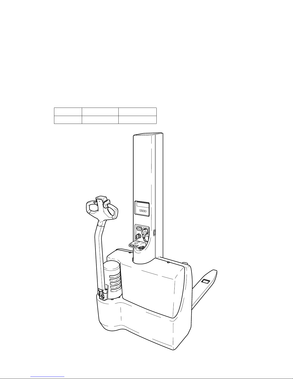
B Description of the truck
1 Application
The truck is intended for transporting goods on a level floor. It can pick up pallets that
are open to the ground or trolleys. The capacity of the truck can be found on the
capacity label Qmax.
m
The EMC/EMB truck has been designed for light duty, maximum continuous
operation should not exceed 2 hours.
Truck type, load capacity and motor output:
Type Load capacity Motor output
EMC/EMB 1000 kg 0.35 kW
B 1
0708.GB
B Description of the truck
1 Application
The truck is intended for transporting goods on a level floor. It can pick up pallets that
are open to the ground or trolleys. The capacity of the truck can be found on the
capacity label Qmax.
m
The EMC/EMB truck has been designed for light duty, maximum continuous
operation should not exceed 2 hours.
Truck type, load capacity and motor output:
Type Load capacity Motor output
EMC/EMB 1000 kg 0.35 kW
Page 11

B 2
0708.GB
2 Description of the assemblies and functions
Item EMC/EMB Designation
1
t
Collision protection button
2
t
Mast covering
3
o
Weighing system
4
t
Battery discharge monitor
5
t
Charge control lamp
6
t
Battery charging plug (integrated battery charger, 24 V / 9 A)
7
t
Emergency stop plug
8
t
Load lifting device
9
t
Load-bearing wheel
10
t
Supporting wheel
11
t
Drive wheel
12
t
Front hood
13
t
Motor cover
14
t
Key switch
15
t
Control shaft
16
t
Controller
t = Standard equipment
o = Optional equipment
5
1
16
15
14
12
13
11
10
9
8
7
6
4
3
2
Page 12

B 3
0708.GB
2.1 Truck
Construction: The EMC/EMB is a four-wheel truck with a steerable drive wheel (11),
a supporting wheel (10) and two load-bearing wheels (9). Hoods that are easy to open
(2, 12 and 13) provide easy access to all units. The operating controls are located in
the control shaft head.
Safety features:
- The truck chassis protects the feet of the operator and, in case of collisions, the
load lying on the pallet.
- The control shaft (15) ensures that the operator is at a safe distance from the truck.
In case of danger, its shape allows the control shaft to move upward in front of the
body of the operator, applying the brake.
- When the control shaft is released, a gas pressure spring causes it to be pushed
into the upper braking position.
- The collision protection button (1) in the control shaft head reacts when touched.
The direction of travel is reversed and the truck moves away from the operator.
- Pulling out the emergency stop plug (7) causes all electrical functions to be
deactivated.
Operating controls and indicators: The operating controls for lifting, lowering,
inching speed and the horn function are arranged on the control shaft (15).
The truck is equipped with a battery discharge monitor (4).
A
The discharge monitor (4) deactivates the fast speed function when the voltage is low
to prevent exhaustive discharge.
Drive system: The drive system has an asymmetrical structure. The 0.35 kW drive
motor drives the drive wheel (11) via a transmission. Reversing the direction of travel
by using the controller (16) in the control shaft head allows the truck to be braked by
counter-current braking.
Steering system: The truck is steered using the control shaft (15). The steering
range is approx. 90° to either side.
Brake system: A spring pressure brake (service brake) acts directly upon the drive
motor. Tilting the control shaft (15) into the upper or lower braking area causes the
truck to be braked.
Hydraulic system: The lifting and lowering functions are triggered using the control
buttons on the control shaft head. When the lifting function is activated, the pump unit
starts up. Hydraulic oil is pumped from the oil reservoir into the cylinder. The load
lifting device (8) is lifted.
Electrical system: 24 volt system. As a standard feature, the truck is equipped with
an electronic drive current control system.
Page 13

B 4
0708.GB
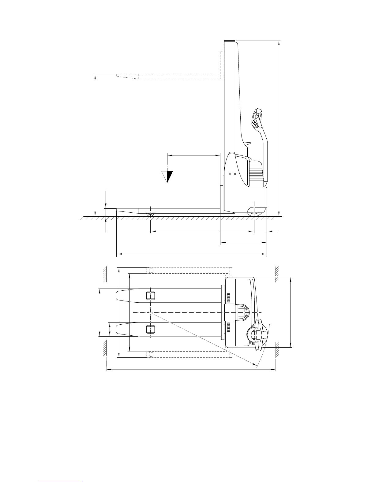
3 Technical data - standard version
A
Technical data specified according to VDI 2198.
Technical data are subject to alteration and additions.
3.1 Performance data for standard trucks
3.2 Dimensions
* Ast includes a safety distance of 200 mm
** Can be adjusted in steps of 50 mm
Designation EMC / EMB
Q Rated load capacity 1000 kg
C Load centre 600 mm
Travelling speed with / without load 3.5 / 4 km/h
Lifting speed with / without load 8.0 / 11.0 cm/s
Lowering speed with / without load 20 / 7 cm/s
Designation Standard EMC
Broad version
EMB
h
1
Hoist frame height 1970 1970 mm
h
3
Lifting height 1560/2000 1560/2000 mm
h
13
Load lifting device lowered 90 90 mm
y
Wheel base, load part
lowered
1170 1170 mm
l
1
Truck length 1710 1710 mm
Distance
drive wheel <-> front chass.
150 150 mm
l
2
Front section length 530 530 mm
b
1
Truck width 800 - mm
Wa Turning radius 1405 1405 mm
Ast*
Aisle width
1000x1200 in transversal dir.
2241 2340 mm
Ast*
Aisle width
800x1200 in longitudinal dir.
2178 2190 mm
b4**
Max. distance between
wheel arms, inside
- 970 - 1270 mm
b1/b2**
Max. distance between
wheel arms, outside
- 1170 - 1470 mm
b
5
Distance between the forks,
outside
540 540 or 660 mm
e Fork width 160 160 mm
B 4
0708.GB
3 Technical data - standard version
A
Technical data specified according to VDI 2198.
Technical data are subject to alteration and additions.
3.1 Performance data for standard trucks
3.2 Dimensions
* Ast includes a safety distance of 200 mm
** Can be adjusted in steps of 50 mm
Designation EMC / EMB
Q Rated load capacity 1000 kg
C Load centre 600 mm
Travelling speed with / without load 3.5 / 4 km/h
Lifting speed with / without load 8.0 / 11.0 cm/s
Lowering speed with / without load 20 / 7 cm/s
Designation Standard EMC
Broad version
EMB
h
1
Hoist frame height 1970 1970 mm
h
3
Lifting height 1560/2000 1560/2000 mm
h
13
Load lifting device lowered 90 90 mm
y
Wheel base, load part
lowered
1170 1170 mm
l
1
Truck length 1710 1710 mm
Distance
drive wheel <-> front chass.
150 150 mm
l
2
Front section length 530 530 mm
b
1
Truck width 800 - mm
Wa Turning radius 1405 1405 mm
Ast*
Aisle width
1000x1200 in transversal dir.
2241 2340 mm
Ast*
Aisle width
800x1200 in longitudinal dir.
2178 2190 mm
b4**
Max. distance between
wheel arms, inside
- 970 - 1270 mm
b1/b2**
Max. distance between
wheel arms, outside
- 1170 - 1470 mm
b
5
Distance between the forks,
outside
540 540 or 660 mm
e Fork width 160 160 mm
Page 14
B 5
0708.GB
C
Q
h
1
h
3
h
13
l
2
y 150
l
1
Ast
b
1
Wa
b
1
/b
2
b
5
e
b
4
B 5
0708.GB
C
Q
h
1
h
3
h
13
l
2
y 150
l
1
Ast
b
1
Wa
b
1
/b
2
b
5
e
b
4
Page 15

B 6
0708.GB
3.3 Batteries and motor output
3.4 EN standards
Continuous sound level: 66 dB(A)
according to prEN 12053 as stipulated in ISO 4871
A
The continous sound level is an average value determined according to standard stipulations and covers the noise level during driving, during lifting and during idling. The
noise level is measured at the driver’s ear.
Electromagnetic compatibility (EMC)
The following limits are observed according to the
product standards “Electromagnetic Compatibility of
Industrial Trucks (9/95)”:
- interference emission (EN 50081-1)
- interference immunity (EN 50 082-2)
- electrostatic discharge (EN 61000-4-2)
A
Electrical or electronic components and their arrangement may only be modified after
written approval by the manufacturer has been obtained.
EMC/EMB
Battery 2x 12 V / 60 Ah or 55 Ah in series
Motor output 0.35 kW
B 6
0708.GB
3.3 Batteries and motor output
3.4 EN standards
Continuous sound level: 66 dB(A)
according to prEN 12053 as stipulated in ISO 4871
A
The continous sound level is an average value determined according to standard sti-
pulations and covers the noise level during driving, during lifting and during idling. The
noise level is measured at the driver’s ear.
Electromagnetic compatibility (EMC)
The following limits are observed according to the
product standards “Electromagnetic Compatibility of
Industrial Trucks (9/95)”:
- interference emission (EN 50081-1)
- interference immunity (EN 50 082-2)
- electrostatic discharge (EN 61000-4-2)
A
Electrical or electronic components and their arrangement may only be modified after
written approval by the manufacturer has been obtained.
EMC/EMB
Battery 2x 12 V / 60 Ah or 55 Ah in series
Motor output 0.35 kW
Page 16

B 7
0708.GB
4 Labels
* EMB with crane hook see chapter G, section 1.3
Item Designation
17 Load capacity label “Load capacity / load centre / fork” *
18 Eye for crane loading
19 Warning sign “Do not step below the load lifting device”
20 Load capacity Qmax *
21 Warning sign “Caution: electronics and low voltage”
22 Label “Application points for lifting jack”
23 Test sticker (o)
24 Truck identification plate *
25 Truck number (embossed)
26 Prohibitive sign “Do not ride on the truck”
X xx xx
xxxx xx
Xxx
Xxxx
Xxxx
Xxxx
Xxxxxxx
Xxxxxx
Xxxxxxxx
Xxxxxx
Xxxxxx
Xxxxxxxxx
Xxxxxxxxxx
Xxxxxxxxx
Xxxxxxxxx
Xxxxx
Xxxxx
Xxxxx
Xxxxx
Xxxxxxx
Xxxxxxxxxx
Xxxxxx
Xxxxxxxxx
Xxxxxx
Xxxxxx
Xxxxxxx
Xxxxxx
Xxxxxx
Xxxxxxxxxxxxxx
Xxxxxxxxxxxxxxx
Xxxxxxx
Xxxxxxxxxxxxxxxxxxxx
Xxxxxxxxxxxxxxxxxxxxx
Xxxxxxxxxxxxxxxxxxx
Xxxxxxxxxxxxxxxxxxxx
Xxxxxxxxxxxxxxxxxxx
Xxxxxxxxxxxxxxxxx
Xxxxxxxxxxxxxxxxxxxxxxxxx
Xxxxxxxxxxxxxxxxxx
Xxxxxxxxxxxxxxxxxx
Xxxxxxxxxxxxxxxxxx
Xxxxxxxxxxxxxxxxxxxxxx
Xxxxxxxxxxxxxxxxxx
Xx
18
25
19
26
24
17
Q
max
1000
kg
20
21
mV
1,5 V
22
1
2
1
1
1
0
9
8
7
6
5
4
3
2
1
1994
Regelmäßige Prüfung
nach UVV VBG 12 a/ 12 b
§20 durch Sachkundigen
Nächste Prüfung
Ihr Kundendienst-Partner
Kundendienst
JUNGHEINRICH
V
23
Page 17

B 8
0708.GB
4.1 Truck identification plate
A
In the event of queries relating to the truck or spare part orders, please state the serial
no. (28) of the truck.
4.2 Load capacity label, load capacity / load centre / fork
The load capacity label (17) indicates the load capacity
Q kg of the fork. A diagram shows the actual load capacity
at different load centres (C in mm).
Item Designation Item Designation
27 Type 33 Load centre in mm
28 Serial no. (truck no.) 34 Min./max. battery weight in kg
29 Order no. 35 Net weight without battery in kg
30 Rated load capacity in kg 36 Year of manufacture
31
Battery: Voltage V
Ampere hours Ah
37 Type no.
32 Manufacturer
X xx xx
xxxx xx
Xxx
Xxxx
Xxxx
Xxxx
Xxxxxxx
Xxxxxx
Xxxxxxxx
Xxxxxx
Xxxxxx
Xxxxxxxxx
Xxxxxxxxxx
Xxxxxxxxx
Xxxxxxxxx
Xxxxx
Xxxxx
Xxxxx
Xxxxx
Xxxxxxx
Xxxxxxxxxx
Xxxxxx
Xxxxxxxxx
Xxxxxx
Xxxxxx
Xxxxxxx
Xxxxxx
Xxxxxx
Xxxxxxxxxxxxxx
Xxxxxxxxxxxxxxx
Xxxxxxx
Xxxxxxxxxxxxxxxxxxxx
Xxxxxxxxxxxxxxxxxxxxx
Xxxxxxxxxxxxxxxxxxx
Xxxxxxxxxxxxxxxxxxxx
Xxxxxxxxxxxxxxxxxxx
Xxxxxxxxxxxxxxxxx
Xxxxxxxxxxxxxxxxxxxxxxxxx
Xxxxxxxxxxxxxxxxxx
Xxxxxxxxxxxxxxxxxx
Xxxxxxxxxxxxxxxxxx
Xxxxxxxxxxxxxxxxxxxxxx
Xxxxxxxxxxxxxxxxxx
Xx
27
28
29
30
31
33
37
36
35
34
32
Page 18
C 1
0600.GB
C Transportation and commissioning
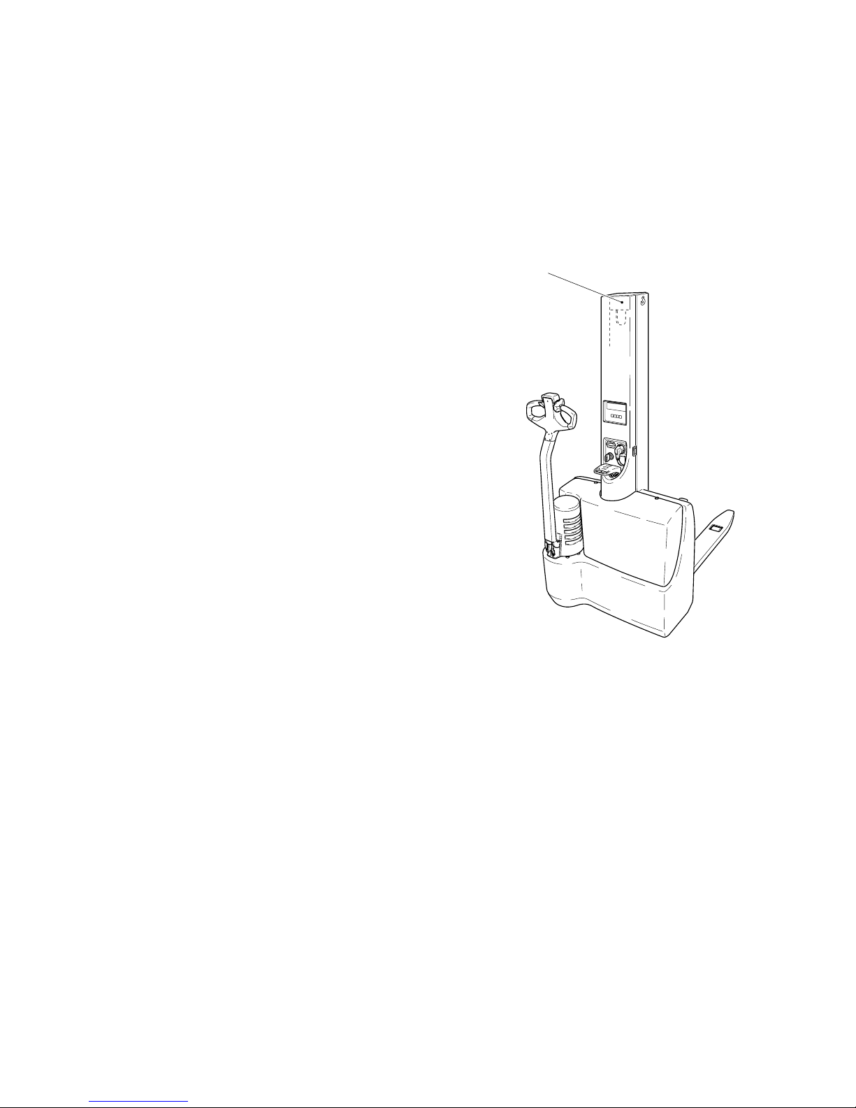
1 Transportation by crane
m
Only use lifting gear of adequate capacity
(loading weight = dead weight + battery weight; see truck identification plate).
A
A lifting eye (1) is provided on the fork side of the mast for loading the truck using
crane gear.
- Park the truck and render it safe
(see chapter E, section 4.5).
- Attach the crane gear to the lifting eye (1).
m
The crane gear must be attached to the lifting eye
in such a manner that it cannot slip!
The crane gear must be attached in such a
manner that it does not touch any attachments
during lifting.
2 Commissioning
m
The truck must only be operated on battery
current! Rectified alternating current will damage
the electronic components. Cables connected to
the battery (trailing cables) must be less than 6 m
in length.
To prepare the truck for operation after delivery or
transportation, the following operations must be
performed:
- Check the equipment for completeness.
- If necessary, install the battery. Make sure that the battery cable is not damaged.
- Charge the battery (see chapter D, section 3).
- Put the truck into operation in the stipulated manner (see chapter E, section 3).
A
When the truck is parked, the surface of the tyres may flatten. The flattening will
disappear after the truck has been operated for a short time.
1
C 1
0600.GB
C Transportation and commissioning
1 Transportation by crane
m
Only use lifting gear of adequate capacity
(loading weight = dead weight + battery weight; see truck identification plate).
A
A lifting eye (1) is provided on the fork side of the mast for loading the truck using
crane gear.
- Park the truck and render it safe
(see chapter E, section 4.5).
- Attach the crane gear to the lifting eye (1).
m
The crane gear must be attached to the lifting eye
in such a manner that it cannot slip!
The crane gear must be attached in such a
manner that it does not touch any attachments
during lifting.
2 Commissioning
m
The truck must only be operated on battery
current! Rectified alternating current will damage
the electronic components. Cables connected to
the battery (trailing cables) must be less than 6 m
in length.
To prepare the truck for operation after delivery or
transportation, the following operations must be
performed:
- Check the equipment for completeness.
- If necessary, install the battery. Make sure that the battery cable is not damaged.
- Charge the battery (see chapter D, section 3).
- Put the truck into operation in the stipulated manner (see chapter E, section 3).
A
When the truck is parked, the surface of the tyres may flatten. The flattening will
disappear after the truck has been operated for a short time.
1
Page 19

C 2
0600.GB
3 Moving an incapacitated truck (emergency operation)
To move the truck by emergency operation, the electromagnetically applied brake
must be released.
- Remove the motor cover (2).
- Turn the screws (3) in clockwise direction until reaching the stop.
The truck can now be moved.
m
After the truck has been parked at its destination, the screws (3) must be turned again
anti-clockwise by 1½ revolutions. This restores the braking effect.
2
3
Page 20

D 1
0600.GB
D Battery - Servicing, recharging, replace-
ment
1 Safety regulations governing the handling of lead-acid batteries
The truck must be parked and rendered safe before any operations on batteries are
undertaken (refer to chapter E).
Servicing staff: Recharging, servicing and replacing of batteries must only be
performed by qualified personnel. The instructions contained in this operating
manual, and the instructions of the manufacturer of the battery and of the battery
recharging station, must be observed when performing the above operations.
Fire protection measures: Smoking and naked flames are not permitted when
handling batteries. No inflammable substances or spark-generating materials must
be present or stored within a distance of 2 meters of the truck parked for battery
recharging. The location must be well ventilated and fire fighting equipment must be
kept ready.
Servicing of batteries: The battery cell screw caps must be kept dry and clean.
Terminals and cable shoes must be clean, lightly greased with pole grease and must
be securely tightened. Batteries with bare terminal posts must be covered using a
non-skid insulating mat.
Disposal of the battery: Batteries must only be disposed of as stipulated in the
national environmental protection regulations or waste disposal provisions. The
manufacturer’s specifications for the disposal must be heeded.
m
Before closing the battery hood, make sure that the battery cable cannot be
damaged.
f
Batteries contain dissolved acid which is toxic and caustic. For this reason, protective
clothing and goggles must be worn whenever work is undertaken on batteries. Avoid
physical contact with battery acid. If clothing, skin or eyes accidentally come into contact with battery acid, liberally flush the affected parts with clean water. Consult a doctor when skin or eyes come into contact with battery acid. Spilled battery acid must
be immediately neutralized.
m
Only batteries with closed tray may be used.
f
Battery weight and dimensions have considerable influence on operational safety of
the truck. Changing the battery equipment is not permitted without prior approval by
the manufacturer.
2Battery types
m
The truck is equipped with maintenance-free battery types (refer to chapter B). These
batteries must NOT refilled with distilled water. The covers of the cells are tightly
closed. Opening the covers will destroy the battery!
The battery weight is given on the battery identification plate.
D 1
0600.GB
D Battery - Servicing, recharging, replace-
ment
1 Safety regulations governing the handling of lead-acid batteries
The truck must be parked and rendered safe before any operations on batteries are
undertaken (refer to chapter E).
Servicing staff: Recharging, servicing and replacing of batteries must only be
performed by qualified personnel. The instructions contained in this operating
manual, and the instructions of the manufacturer of the battery and of the battery
recharging station, must be observed when performing the above operations.
Fire protection measures: Smoking and naked flames are not permitted when
handling batteries. No inflammable substances or spark-generating materials must
be present or stored within a distance of 2 meters of the truck parked for battery
recharging. The location must be well ventilated and fire fighting equipment must be
kept ready.
Servicing of batteries: The battery cell screw caps must be kept dry and clean.
Terminals and cable shoes must be clean, lightly greased with pole grease and must
be securely tightened. Batteries with bare terminal posts must be covered using a
non-skid insulating mat.
Disposal of the battery: Batteries must only be disposed of as stipulated in the
national environmental protection regulations or waste disposal provisions. The
manufacturer’s specifications for the disposal must be heeded.
m
Before closing the battery hood, make sure that the battery cable cannot be
damaged.
f
Batteries contain dissolved acid which is toxic and caustic. For this reason, protective
clothing and goggles must be worn whenever work is undertaken on batteries. Avoid
physical contact with battery acid. If clothing, skin or eyes accidentally come into con-
tact with battery acid, liberally flush the affected parts with clean water. Consult a doc-
tor when skin or eyes come into contact with battery acid. Spilled battery acid must
be immediately neutralized.
m
Only batteries with closed tray may be used.
f
Battery weight and dimensions have considerable influence on operational safety of
the truck. Changing the battery equipment is not permitted without prior approval by
the manufacturer.
2Battery types
m
The truck is equipped with maintenance-free battery types (refer to chapter B). These
batteries must NOT refilled with distilled water. The covers of the cells are tightly
closed. Opening the covers will destroy the battery!
The battery weight is given on the battery identification plate.
Page 21

D 2
0600.GB
3 Charging the battery using the integrated charger
The mains cable of the charger is accessible from outside.
- Pull the mains plug (1) out of the receptacle (2) on the charger and plug it into a
suitable electric outlet (220 - 240V ±10%). When flashing green (possibly yellow
steady on) the LED (3) indicates that the charger is connected to mains.
- Charge the battery until LED (3) is steady on (green).
- Pull the plug (1) out of the electric outlet and insert it into the receptacle of the safety
circuit on the truck (2).
A
If the mains plug (1) is not in the receptacle (2) of the safety cut-out, all electrical
functions are interrupted. In this state, the truck cannot be operated.
Trickle charging
The battery is completely charged when the green LED (3) is continuously lit. The
charger switches to trickle charging. Trickle charging continues until the mains plug
is pulled out of the electric outlet.
Mains supply
Mains voltage: 220 - 240 V ±10%
Mains frequency: 50 Hz ±4%
1
3
2
Page 22

D 3
0600.GB
Charging times
Depending on the state of discharge, charging the battery can take up to 11 h.
Partial charging
The charger is designed in such a manner that it automatically adapts itself when
charging partially charged batteries. This keeps battery wearing down.
m
Red flashing of LED (3) means that the battery is defective or the charging circuit has
been interrupted.
4 Replacing the batteries
- Loosen the screws (4) and remove the front hood (5).
- Loosen the terminal screws (7) and remove the battery cables from the terminals.
m
Place the battery cables in such a manner that they do not get caught on the truck
when the battery is pulled out.
- Lift out the batteries (6) using the hinged handle.
4
5
6
7
+
+
-
-
1.
2.
Page 23

D 4
0600.GB
m
Installation is in the reverse order. When installing the battery, make sure that it is in
the correct position and that the batteries are correctly connected:
- red cable: + terminal of the 1st battery
- blue cable: - terminal of the 2nd cable
- After the battery has been reinstalled, check all cable connections and plugged
connections for visible damage.
5 Battery discharge monitor
The charging condition of the battery is indicated in 10%
increments by a moving bar.
As the battery discharges, the bar moves from right to left.
Battery charging is recommended when the capacity has
dropped to approx. 30%.
A
At a residual capacity of 20%, the fast speed function is deactivated. The truck can
only be moved at inching speed. The fast speed function will not be released again
until the connected battery has been recharged completely.
m
Continued operation with the fast speed function deactivated can damage the battery
and leads to the battery being totally depleted. In this state, the battery voltage falls
below the permissible minimum value and charging by means of the charger is no
longer possible (the green LED does not flash when the mains plug is plugged into
the mains outlet). Contact the service department to correct this fault.
Page 24

E 1
0600.GB
E Operation
1 Safety regulations governing the operation of the fork-lift truck
Driving permission: The fork-lift truck must only be operated by persons who have
been trained in the operation of trucks, who have demonstrated to the user or his
representative their capability of moving and handling loads, and who have expressly
been charged by the user or his representative with the operation of the truck.
Rights, duties and conduct of the driver: The driver must be: informed of his rights
and duties; trained in the operation of the fork-lift truck; and familiar with the contents
of these operating instructions. All necessary rights must be granted to him. If the
fork-lift truck can be used in the pedestrian-controlled mode, the driver must wear
safety boots when operating the truck.
Prohibition of unauthorized use: The driver is responsible for the fork-lift truck
during working time. He must forbid unauthorized persons to drive or operate the forklift truck. The transport or lifting of persons is forbidden.
Damage and defects: Damage or defects noted on the fork-lift truck or on the
attachments must immediately be brought to the notice of the person in charge. Forklift trucks that cannot be safely operated (e.g. due to worn tyres or defective brakes)
must not be used until they have been properly repaired.
Repairs: Without specific training and express authorization the driver is not allowed
to perform any repairs or modifications on the fork-lift truck. Under no circumstances
must the driver change the setting of switches or safety installations, or render them
ineffective.
Danger area: As danger area is considered the area within which persons are
endangered by the travelling or lifting movements of the fork-lift truck or its load lifting
devices (e.g. fork or attachments), or by the loads being transported. This includes
also the area within reach of dropping loads or dropping truck attachments.
f
Unauthorized persons must be asked to leave the danger area. The driver must give
a warning signal, whenever a situation presenting danger to persons might develop.
The fork-lift truck must immediately be brought to a standstill, if persons, although
asked, do not leave the danger area.
Safety devices and warning labels: The safety devices, warning labels and warning
notes described in the present operating instructions must always be heeded.
E 1
0600.GB
E Operation
1 Safety regulations governing the operation of the fork-lift truck
Driving permission: The fork-lift truck must only be operated by persons who have
been trained in the operation of trucks, who have demonstrated to the user or his
representative their capability of moving and handling loads, and who have expressly
been charged by the user or his representative with the operation of the truck.
Rights, duties and conduct of the driver: The driver must be: informed of his rights
and duties; trained in the operation of the fork-lift truck; and familiar with the contents
of these operating instructions. All necessary rights must be granted to him. If the
fork-lift truck can be used in the pedestrian-controlled mode, the driver must wear
safety boots when operating the truck.
Prohibition of unauthorized use: The driver is responsible for the fork-lift truck
during working time. He must forbid unauthorized persons to drive or operate the fork-
lift truck. The transport or lifting of persons is forbidden.
Damage and defects: Damage or defects noted on the fork-lift truck or on the
attachments must immediately be brought to the notice of the person in charge. Fork-
lift trucks that cannot be safely operated (e.g. due to worn tyres or defective brakes)
must not be used until they have been properly repaired.
Repairs: Without specific training and express authorization the driver is not allowed
to perform any repairs or modifications on the fork-lift truck. Under no circumstances
must the driver change the setting of switches or safety installations, or render them
ineffective.
Danger area: As danger area is considered the area within which persons are
endangered by the travelling or lifting movements of the fork-lift truck or its load lifting
devices (e.g. fork or attachments), or by the loads being transported. This includes
also the area within reach of dropping loads or dropping truck attachments.
f
Unauthorized persons must be asked to leave the danger area. The driver must give
a warning signal, whenever a situation presenting danger to persons might develop.
The fork-lift truck must immediately be brought to a standstill, if persons, although
asked, do not leave the danger area.
Safety devices and warning labels: The safety devices, warning labels and warning
notes described in the present operating instructions must always be heeded.
Page 25

E 2
0600.GB
2 Description of the operating controls and indicators
Item Control or indicator EMC/EMB Function
1 Collision protection button t The truck moves away from the
operator.
2 Controller t Controls the direction and speed
of travel.
3 Button “Lift load lifting device” t For lifting the load lifting device.
4 Button “Lower load lifting
device”
t For lowering the load lifting
device.
5 Button “Horn” t Triggers an acoustic signal.
6 Weighing system o Indicates the weight of the load
that has been picked up.
7 LED “Charging state” t Indicates the charging state of
the battery (see chapter D,
section 3).
8 Integrated charger
(incl. safety cut-out)
t The battery is charged when the
mains plug is plugged into an
electric outlet.
9 Emergency stop plug t The circuit is interrupted, all
electrical functions are switched
off.
10 Key switch t For switching the control current
on and off. Removing the key
prevents the truck from being
switched on by unauthorised
persons.
11 Battery discharge monitor t Indicates the remaining capacity
of the battery (see chapter D,
section 5).
t = Standard equipment o = Optional equipment
Page 26

E 3
0600.GB
5
2
1
10
11
6
8
9
4
3
7
E 3
0600.GB
5
2
1
10
11
6
8
9
4
3
7
Page 27

E 4
0600.GB
3 Starting up the truck
f
The driver must make sure that nobody is within the danger area of the truck before
the truck is switch on or operated or before a load is lifted.
Checks and operations to be performed before starting daily work
- Check the entire truck (especially the wheels and the load lifting device) for
damage.
Switching on the truck
- Check that the battery plug (8) and the emergency stop plug (9) are plugged.
- Insert the key into the key switch (10) and turn it clockwise until reaching the stop.
A
The battery discharge indicator indicates the remaining capacity of the battery.
- Check the “Horn” button (5) for proper functioning by pressing it.
The truck is now ready for operation.
- Check the braking function of the control shaft (see chapter E, section 4.2).
5
10
8
9
Page 28

E 5
0600.GB
4 Operation of the fork-lift truck
4.1 Safety regulations applicable when operating the truck
Driving lanes and work areas: Only such lanes and routes that are specially
allocated for truck traffic must be used. Unauthorized persons must stay away from
work areas. Loads must only be stored at places specially provided for this purpose.
Driving conduct: The travelling speed must be adapted to the prevailing local
conditions. The truck must be driven at slow speed when negotiating bends or narrow
passages, when passing through swing doors and at blind spots. The driver must
always observe an adequate braking distance between the fork-lift truck and the
vehicle in front and he must be in control of his truck at all times. Sudden stopping
(except in emergencies), rapid U-turns and overtaking at dangerous or blind spots is
not permitted. It is forbidden to lean out of or reach beyond the working and operating
area.
Visibility: The driver must look in the direction of travel and must always have a clear
view of the route ahead. When loads blocking the view are carried, the fork-lift truck
must be driven with the load at the rear. If this is not possible, a second person must
walk in front of the fork-lift truck to give suitable warnings.
Negotiating slopes and inclines: Negotiating of slopes and inclines is permitted
only, when they are recognized lanes, when they are clean and non-slipping, and
when the technical specification of the truck permits safe driving on such slopes or
inclines. Loads must always be carried at that end of the truck facing uphill. U-turns,
cutting obliquely over slopes or inclines and parking of the fork-lift truck on slopes or
inclines is not permitted. Inclines must only be negotiated at slow speed with the
driver ready to brake at any moment.
Use of lifts and driving on loading platforms: Lifts and loading platforms must only
be used, if they are of adequate load bearing capacity, if suitable for driving on, and
if authorized by the user of the truck for truck traffic. The fork-lift truck driver has to
satisfy himself accordingly before driving into lifts or on to loading platforms. The truck
must enter lifts with the load in front and must take up a position which does not allow
it to come into contact with the walls of the lift shaft. Persons riding in the lift together
with the fork-lift truck must only enter the lift after the fork-lift truck has come safely to
a standstill, and must leave the lift before the fork-lift truck.
Nature of the loads carried: Only loads that have been safely and correctly secured
must be carried. Never transport loads stacked higher than the top of the fork
carriage, or stacked higher than the guard grille.
Towing trailers: The maximum trailer load given for the fork-lift truck for braked and/
or unbraked trailers must not be exceeded. The trailer load must be properly secured
and must not exceed the dimensions permitted for the driving routes. After attaching
the trailer but before starting driving, the driver must check that the trailer attachment
is secured against detachment. Towing fork-lift trucks must be operated in such a
manner that safe driving and braking of the truck and the trailer is guaranteed for all
driving movements.
Page 29

E 6
0600.GB
4.2 Driving, steering, braking
f
It is not admissible to stay on the vehicle during driving.
Emergency stop
- Pull out the emergency stop plug (9).
All of the electrical functions are switched off.
Automatic braking
Releasing the control shaft causes automatic braking - the control shaft automatically
moves into the upper braking range (B).
f
If the control shaft moves to the braking position more slowly than normal, the cause
must be determined and eliminated. If necessary, the gas pressure spring must be
replaced.
Driving
m
Only drive with the hoods closed and properly locked.
- Start up the truck (see chapter E, section 3).
The travelling speed can be controlled using the controller (2).
- Tilt the control shaft (12) into the driving range (F) and set the controller (2) to the
desired direction (V or R).
Steering
- Swivel the control shaft (12) to the left or the right.
m
In narrow bends, the control shaft protrudes beyond the truck contour!
0
R
R
V
B
F
B
V
12
9
2
Page 30

E 7
0600.GB
Braking
f
The braking behaviour of the truck strongly depends on the state of the floor. This
must be taken into account by the driver for his driving behaviour.
The truck can be braked in three ways:
- by using the generator brake (controller (2))
- by counter-current braking (controller (2))
- by using the service brake (control shaft (12))
Braking using the generator brake:
- Release the controller (2).
Counter-current braking:
- While driving, switch the controller (2) to the opposite direction.
- The truck is decelerated by counter-current braking until it starts moving in the
opposite direction.
f
In case of emergency, the service brake must be used to brake the truck.
Braking using the service brake:
- Tilt the control shaft (12) upwards or downwards into one of the braking ranges (B).
Accelerating on slopes
m
The load must face uphill!
The slope to be negotiated must not exceed 10 m in length:
- without load: 10 %
- load of 600 kg: 5 %
- load of 1000 kg: 3.5 %
m
Do not negotiate slopes exceeding the values given above with the EMC/EMB.
Successive slopes may only be negotiated after longer breaks.
To prevent the truck from rolling downhill when the control shaft is tilted into the
driving range (F), proceed as follows:
- Tilt the control shaft (12) into the braking range (B).
- Turn the controller (2) into the direction of travel (direction of the fork) until reaching
the stop.
- Tilt the control shaft into the driving range (F).
Page 31

E 8
0600.GB
4.3 Picking up and setting down loads
m
Before picking up a load, the driver must make sure that the load rests properly on its
pallet and that it does not exceed the maximum load capacity of the truck.
Picking up long loads crosswise is not permitted.
- Move the truck so that the load lifting device passes completely below the load.
A
The lifting and lowering speeds are preset.
Lifting
- Press the “Lift load lifting device” button (3) until the required lifting height has been
reached.
m
Immediately release the button when the load lifting device reaches the end stop.
Lowering
- Press the “Lower load lifting device” button (4).
4103
Page 32

E 9
0600.GB
4.4 EMB wheel arm adjustment
Adjust the right- and left-hand wheel arms one after the other.
f
Make sure that both wheel arms are pulled out evenly.
A
The wheel arms can be adjusted in steps of 25 mm.
- Protect the truck from rolling away and use a lifting jack at the jack-up point (13) to
lift one side of the truck.
- Completely unscrew the SW14 hexagon socket head cap screw (15) and remove
it along with the washer (16).
- Adjust the wheel arm (14) to the desired width. The thread must align with the bore.
- Screw in the screw with the washer (15, 16) and tighten it using a torque wrench
(torque = 195 Nm).
- Lower the lifting jack and remove the objects that protect the truck from rolling
away.
- Adjust the other wheel arm in the same manner.
4.5 Parking the truck and rendering it safe
f
Always render the truck safe when parking it.
Do not park the truck on slopes.
The load lifting device must always be completely lowered.
- Lower the load lifting device.
- Switch the key switch (10) to the vertical position and remove the key.
16
15
13
13
14
Page 33

Page 34

F 1
0708.GB
F Maintenance of the fork-lift truck
1 Operational safety and environmental protection
The checks and servicing operations contained in this chapter must be performed in
accordance with the intervals as indicated in the servicing checklists.
f
Modifications of fork-lift truck assemblies, especially of the safety installations, are not
permitted. On no account must the operational speeds of the truck be changed.
m
Only original spare parts have been passed by our quality assurance service. To
ensure safe and reliable operation of the fork-lift truck, only spare parts of the
manufacturer must be used. Old parts, oils and fuels must be disposed of in
accordance with the applicable environmental protection regulations. For oil
changes, the oil service of the manufacturer is available to you.
Upon completion of any checking and servicing activities, the operations contained in
section "Recommissioning" must be performed (refer to chapter F).
2 Safety regulations applicable to truck maintenance
Servicing and maintenance personnel: The fork-lift truck must only be serviced
and maintained by trained personnel of the manufacturer. The service organization
of the manufacturer has external technicians trained especially for these
assignments. We thus recommend signing a maintenance contract with the relevant
service location of the manufacturer.
Lifting and jacking up: When a fork-lift truck is to be lifted, the lifting gear must only
be secured to the points specially provided for this purpose. When the truck is to be
jacked up, suitable measures must be taken to prevent the truck from slipping or
tipping over (use of wedges, wooden blocks). Work underneath the raised load lifting
device must only be carried out when the fork is immobilised and supported by a
chain of adequate strength.
Cleaning operations: No inflammable liquids must be used when cleaning the forklift truck. Prior to the commencement of cleaning operations, all safety measures
have to be taken as are required to prevent sparking (e.g. by short-circuits). For
battery-operated fork-lift trucks, the battery plug must be removed. Only weak indraft,
weak compressed air and non-conducting, antistatic brushes must be used for the
cleaning of electric or electronic assemblies.
m
If the fork-lift truck is to be cleaned using a water jet or a high-pressure cleaner, all
electric and electronic components must be carefully covered beforehand because
moisture can lead to incorrect functioning.
Cleaning by means of a steam jet is not admissible.
Upon the completion of cleaning work the operations detailed in section
"Recommissioning" have to be performed.
F 1
0708.GB
F Maintenance of the fork-lift truck
1 Operational safety and environmental protection
The checks and servicing operations contained in this chapter must be performed in
accordance with the intervals as indicated in the servicing checklists.
f
Modifications of fork-lift truck assemblies, especially of the safety installations, are not
permitted. On no account must the operational speeds of the truck be changed.
m
Only original spare parts have been passed by our quality assurance service. To
ensure safe and reliable operation of the fork-lift truck, only spare parts of the
manufacturer must be used. Old parts, oils and fuels must be disposed of in
accordance with the applicable environmental protection regulations. For oil
changes, the oil service of the manufacturer is available to you.
Upon completion of any checking and servicing activities, the operations contained in
section "Recommissioning" must be performed (refer to chapter F).
2 Safety regulations applicable to truck maintenance
Servicing and maintenance personnel: The fork-lift truck must only be serviced
and maintained by trained personnel of the manufacturer. The service organization
of the manufacturer has external technicians trained especially for these
assignments. We thus recommend signing a maintenance contract with the relevant
service location of the manufacturer.
Lifting and jacking up: When a fork-lift truck is to be lifted, the lifting gear must only
be secured to the points specially provided for this purpose. When the truck is to be
jacked up, suitable measures must be taken to prevent the truck from slipping or
tipping over (use of wedges, wooden blocks). Work underneath the raised load lifting
device must only be carried out when the fork is immobilised and supported by a
chain of adequate strength.
Cleaning operations: No inflammable liquids must be used when cleaning the fork-
lift truck. Prior to the commencement of cleaning operations, all safety measures
have to be taken as are required to prevent sparking (e.g. by short-circuits). For
battery-operated fork-lift trucks, the battery plug must be removed. Only weak indraft,
weak compressed air and non-conducting, antistatic brushes must be used for the
cleaning of electric or electronic assemblies.
m
If the fork-lift truck is to be cleaned using a water jet or a high-pressure cleaner, all
electric and electronic components must be carefully covered beforehand because
moisture can lead to incorrect functioning.
Cleaning by means of a steam jet is not admissible.
Upon the completion of cleaning work the operations detailed in section
"Recommissioning" have to be performed.
Page 35

F 2
0708.GB
Work on the electric system: Work on the electric system of the truck must only be
performed by staff specially trained for such operations. Before commencing any
work on the electric system, all measures required to prevent electric shocks have to
be taken. For battery-operated fork-lift trucks, the truck must also be depowered by
removing the battery plug.
Welding operations: To prevent any damage to electric or electronic com-ponents,
these have to be removed from the fork-lift truck before any welding operations are
undertaken.
Settings: When repairing or replacing hydraulic, electric or electronic compo-nents
or assemblies, all truck-specific settings have to be retained.
Tyres: The quality of the tyres greatly affects the stability and the driving behaviour
of the fork-lift truck. Changes must only be made following consultations with the
maker. When replacing wheels or tyres, it must be ensured that the fork-lift truck
remains level (tyres and wheels must always be replaced in pairs, i.e. left and right
together).
Hydraulic hoses: The hoses must be renewed every six years. When replacing
hydraulic components, also renew the hoses in this hydraulic system.
Page 36

F 3
0708.GB
3 Maintenance checklist
A
To ensure the safety and service life of the truck, the items listed in the maintenance
checklist must be carried out every 1000 service hours, or at least annually.
m
a) If there are leakages, tighten the screwed connection
on the hydraulic unit with a maximum torque of 35 Nm.
A
W1 service intervals are to be performed by the customer.
In the run-in period - after approx. 100 service hours - or after repair work, the owner
must check the wheel nuts/bolts and re-tighten if necessary.
Chassis /
superstructure:
Check all load bearing elements for damage
Check all bolted connections
Drive unit: Check the transmission for noises and leakage
Wheels:
Check for wear and damage
Check the wheel bearings and ensure secure fastening of
wheels
Check that the wheel bolts are firmly seated; tighten if
necessary
Steering / brake
system:
Check the steering bearing play
Performance and adjustment check
Check the braking function of the gas pressure spring;
check the gas pressure spring for leakage and damage
Lifting device:
Check for correct functioning, adjustment and wear
Check the fork tines and fork carrier for wear and damage
Hydraulic system:
Performance check
Check all connections for leakage and damage a)
Check hydraulic cylinders for leakage, damage and secure
attachment
Check the oil level
Check the pressure limiting valves for correct functioning
Electrical system:
Performance check
Check all cables for secure connection and damage
Check the fuses for correct amperage
Check the warning systems and safety circuits for correct
functioning
Electric motors: Check motor for secure attachment
Batteries:
Check the terminals for secure attachment and apply
grease
Check battery connections for tight fit
Check the battery cables for damage; renew if necessary
Page 37

F 4
0708.GB
4 Hydraulic oil level
5 Fuels, coolants and lubricants
Handling consumption-type material: Consumption-type material must always be
handled properly. Manufacturer’s instructions are to be observed.
f
Improper handling is injurious to health, life and environment. Consumption-type
materials must be stored in adequate containers. They might be inflammable and,
therefore, must not come into contact with hot components or open fire.
When filling in consumption-type materials, use clean containers only. Mixing
consumption-type materials of different grades or qualities is prohibited, except if
mixing is expressly prescribed in these operating instructions.
Avoid spilling. Spilt liquid must be removed immediately using a suitable binding
agent and the mixture of consumption-type material and binding agent is to be
disposed of according to the regulations.
Code Designation Used for:
A H-LP 46, DIN 51524 Hydraulic system
A
2,0 l
Filler plug for
hydraulic oil
1,4 l
Page 38

F 5
0708.GB
6 Notes regarding maintenance
6.1 Preparing the truck for maintenance work
All the required safety measures must be taken in order to prevent any accidents in
the course of maintenance work. Before starting work, prepare the truck as follows:
- Park the truck and render it safe (see chapter E, section 4.5).
- Pull out the emergency stop plug (1).
f
When work is to be carried out under the jacked up truck, immobilise the truck in such
a way that it cannot tip over or slip away. When lifting the truck, the safety instructions
in the chapter “Transportation and commissioning” must also be observed.
6.2 Removing the front hood
- Using a screw driver, unlock the
hood locking mechanism (2).
- Carefully remove the front hood (3).
6.3 Checking the electric fuses
- Prepare the truck for maintenance work (see
chapter F, section 6.1).
- Remove the front hood (see chapter F,
section 6.2).
- Check all fuses for the correct rating and, if
necessary, replace.
Item Designation Type of fuse: EMC/EMB
4 F1 Main fuse 60 A
5 F2 Control fuse 5 A
2
1
3
4
5
6
Page 39

F 6
0708.GB
6.4 Recommissioning the truck
Recommissioning the truck following cleaning or maintenance work is permitted only
after the following operations have been performed:
- Check the brake for correct functioning.
- Check the horn for correct functioning.
7 Decommissioning the truck
If the truck is to be decommissioned for more than six months (e.g. due to
organisational reasons), it must be parked in a frost-free and dry location and all
measures to be taken before, during and following decommissioning must be
performed as detailed below.
m
During decommissioning, the truck must be jacked up in such a manner that the
wheels are clear off the ground. Only this measure will ensure that wheels and wheel
bearings do not suffer damage.
- Recharge the battery (see chapter D, section 3).
- Disconnect and clean the battery. Apply pole grease to the pole screws.
A
In addition, all instructions given by the manufacturer of the battery must be heeded.
- Spray all exposed electrical contacts with a suitable contact spray.
7.1 Measures required during decommissioning
Every 6 months:
- Recharge the battery (see chapter D, section 3).
m
Regular recharging of the battery is very important as self-discharging would cause
excessive depletion of the battery, which would result in the destruction of the battery.
A
If the battery is permanently connected to the charger with trickle charging, the
battery need not be recharged every 6 months to protect it against excessive
depletion.
Page 40

F 7
0708.GB
7.2 Recommissioning the truck after decommissioning
- Thoroughly clean the truck.
- Clean the battery. Grease the pole screws using pole grease and reconnect the
battery.
- Recharge the battery (see chapter D, section 3).
- Check if the hydraulic oil contains condensed water and, if necessary, renew it.
- Start up the truck (see chapter E, section 3).
f
Perform several brake tests immediately after recommissioning the truck.
8 Safety checks to be performed at regular intervals and following any unusual
incidents
A
Carry out a safety check in accordance with national regulations. Junheinrich
recommends checks in accordance with FEM Guideline 4.004. Jungheinrich has a
special safety department with trained personnel to carry out such checks.
The truck must be inspected at least annually (refer to national regulations) or after
any unusual event by a qualified inspector. The inspector shall assess the condition
of the truck from purely a safety viewpoint, without regard to operational or economic
circumstances. The inspector shall be sufficiently instructed and experienced to be
able to assess the condition of the truck and the effectiveness of the safety
mechanisms based on the technical regulations and principles governing the
inspection of forklift trucks.
A thorough test of the truck must be undertaken with regard to its technical condition
from a safety aspect. The truck must also be examined for damage caused by
possible improper use. A test report shall be provided. The test results must be kept
for at least the next 2 inspections.
The owner is responsible for ensuring that faults are immediately rectified.
A
A test plate is attached to the truck as proof that it has passed the safety inspection.
This plate indicates the due date for the next inspection.
9 Final de-commissioning, disposal
A
Final, proper decommissioning or disposal of the truck must be performed in
accordance with the regulations of the country of application. In particular, regulations
governing the disposal of batteries, fuels and electronic and electrical systems must
be observed.
Page 41

F 8
0708.GB
10 Faul localisation and identification
10.1 Fault localisation
A
If the fault cannot be eliminated, decommission the truck and inform the service
department.
10.2 Fault identification (flash codes emitted by the LED on the control board)
The control board is fitted with an LED for fault identification purposes (6). The type
of fault can be identified by the flash signal.
m
The faults described below must only be eliminated by trained personnel or aftersales service technicians.
Fault Possible cause Remedial action
Truck does
not move
- Battery plug not
connected
- Key switch in vertical
position
- Battery charge
insufficient
- Fuse defective
- Mains plug is not in the
receptacle on the truck
- Check and, if necessary, connect the
battery plug
- Move the key in clockwise direction until
reaching the stop
- Check the battery charging condition
and, if necessary, recharge the battery
- Check fuses F1 and F2
- Insert the mains plug into the receptacle
on the truck
Load cannot
be lifted
- Truck is not operational
- Hydraulic oil level too
low
- Fuse defective
- Button “Lift load lifting
device” defective
- Perform all remedial actions listed
under “Truck does not move”
- Check the hydraulic oil level
- Check fuse F1
- Check the button for correct functioning
according to the operating diagram
Load cannot
be lowered
- Button “Lower load
lifting device” defective
- Solenoid valve
defective
- Hydraulic oil level too
low
- Fuse defective
- Check the button for correct functioning
according to the operating diagram
- Check the solenoid valve for correct
functioning according to the operating
diagram
- Check the hydraulic oil level
- Check fuse F1
6
F 8
0708.GB
10 Faul localisation and identification
10.1 Fault localisation
A
If the fault cannot be eliminated, decommission the truck and inform the service
department.
10.2 Fault identification (flash codes emitted by the LED on the control board)
The control board is fitted with an LED for fault identification purposes (6). The type
of fault can be identified by the flash signal.
m
The faults described below must only be eliminated by trained personnel or after-
sales service technicians.
Fault Possible cause Remedial action
Truck does
not move
- Battery plug not
connected
- Key switch in vertical
position
- Battery charge
insufficient
- Fuse defective
- Mains plug is not in the
receptacle on the truck
- Check and, if necessary, connect the
battery plug
- Move the key in clockwise direction until
reaching the stop
- Check the battery charging condition
and, if necessary, recharge the battery
- Check fuses F1 and F2
- Insert the mains plug into the receptacle
on the truck
Load cannot
be lifted
- Truck is not operational
- Hydraulic oil level too
low
- Fuse defective
- Button “Lift load lifting
device” defective
- Perform all remedial actions listed
under “Truck does not move”
- Check the hydraulic oil level
- Check fuse F1
- Check the button for correct functioning
according to the operating diagram
Load cannot
be lowered
- Button “Lower load
lifting device” defective
- Solenoid valve
defective
- Hydraulic oil level too
low
- Fuse defective
- Check the button for correct functioning
according to the operating diagram
- Check the solenoid valve for correct
functioning according to the operating
diagram
- Check the hydraulic oil level
- Check fuse F1
6
Page 42

F 9
0708.GB
The flash or light codes have the following meaning:
10.3 Circuit diagram
A
The circuit diagram for the EMC/EMB can be found on the following page.
Flash or light
code
Possible cause Fault elimination
1x - Control logic not OK
- Switch the truck off and on
again using the key switch.
- Replace the control system.
2x
- The controller was actuated
while switching on
- The correct switch-on
sequence was not heeded
- Switch off the truck.
- Set the controller to the
position O.
- Switch the truck on again
and start up in the correct
order.
- Controller wiring incorrect after
controller was replaced
Check the wiring of the
controller; if necessary, correct
the wiring.
3x - Motor connection not OK
- Check the motor
connections; if necessary,
connect the motor.
- Short-circuit between motor
and housing
- Check whether a shortcircuit has occured; if
necessary, eliminate the
cause properly.
4x
- Controller potentiometer
outside tolerance.
- Replace controller.
5x
- Current sensor defective
- Control logic defective
- Replace the control system.
7x
- Excess temperature (>75 °C)
triggered with hot control
system
- Check the motor current; if
necessary, eliminate the
mechanical or electrical
overload.
- Excess temperature (>75 °C)
triggered with cold control
system (heat dissipator)
- Replace the control system.
8x - General relay coil defective - Replace the control system.
Continuous
flashing
- Battery capacity too low - Recharge the battery.
Continuously lit
- Both directions of travel have
been actuated simultaneously
- Check and, if necessary,
replace the wiring.
- Check the controller for
correct functioning; if
necessary, replace it.
F 9
0708.GB
The flash or light codes have the following meaning:
10.3 Circuit diagram
A
The circuit diagram for the EMC/EMB can be found on the following page.
Flash or light
code
Possible cause Fault elimination
1x - Control logic not OK
- Switch the truck off and on
again using the key switch.
- Replace the control system.
2x
- The controller was actuated
while switching on
- The correct switch-on
sequence was not heeded
- Switch off the truck.
- Set the controller to the
position O.
- Switch the truck on again
and start up in the correct
order.
- Controller wiring incorrect after
controller was replaced
Check the wiring of the
controller; if necessary, correct
the wiring.
3x - Motor connection not OK
- Check the motor
connections; if necessary,
connect the motor.
- Short-circuit between motor
and housing
- Check whether a short-
circuit has occured; if
necessary, eliminate the
cause properly.
4x
- Controller potentiometer
outside tolerance.
- Replace controller.
5x
- Current sensor defective
- Control logic defective
- Replace the control system.
7x
- Excess temperature (>75 °C)
triggered with hot control
system
- Check the motor current; if
necessary, eliminate the
mechanical or electrical
overload.
- Excess temperature (>75 °C)
triggered with cold control
system (heat dissipator)
- Replace the control system.
8x - General relay coil defective - Replace the control system.
Continuous
flashing
- Battery capacity too low - Recharge the battery.
Continuously lit
- Both directions of travel have
been actuated simultaneously
- Check and, if necessary,
replace the wiring.
- Check the controller for
correct functioning; if
necessary, replace it.
Page 43

F 10
0708.GB
Legend for the circuit diagram
1 Drive motor 13 2nd driving stage / potentiometer
2 Charger 14 Emergency reversal
3 Pump motor 15 Horn
4 Main fuse 16 Lifting
5 Control fuse 17 Lowering
6 Key-operated switch 18 Pump contactor
7 Accidental starting protection 19 Lowering valve
8 Control shaft switch 20 Control system
9 Battery monitor 21 Horn
10 Magnetic brake 22 Battery
11 Forwa r d s
12 Reverse
M
M
10
1
3
18
21
20
18
19
11
8
9
6
D6
D2
M1
-B +B
M2
D3
D5
D1
D4
E4
E2
E1
E3
F4
F2
F9
F3
F10
F14
F1
F8
G4
G2
G1
G3
F6
22
5
4
2
7
12
13
14
15
16
17
11
12
13
14
15
16
17
Page 44

G 1
0600.GB
G Attachments
1 Crane hook
1.1 Proper use
Using approved fastening gear, the electric control shaft fork lift truck EMB with crane
hook can be used for lifting and transporting loads. Pulling or pushing of loads attached to the crane hook is not permitted.
f
Before commissioning the truck, make sure that the bolt that fixes the crane arm is
properly secured!
Loads may only be lifted and transported if they do not exceed the permitted load
centres and the pertaining load capacities (Qmax) (see load diagram “Load
capacity / load centre / crane hook”).
The truck may only be moved with a load attached to the hook when the load is secured and has been lowered as far as possible.
A
Eyes for securing the load are provided on the vertical part of the crane arm.
m
The general stipulations regarding the proper use of the truck contained in chapter A
of the present operating instructions continue to remain valid.
G 1
0600.GB
G Attachments
1 Crane hook
1.1 Proper use
Using approved fastening gear, the electric control shaft fork lift truck EMB with crane
hook can be used for lifting and transporting loads. Pulling or pushing of loads atta-
ched to the crane hook is not permitted.
f
Before commissioning the truck, make sure that the bolt that fixes the crane arm is
properly secured!
Loads may only be lifted and transported if they do not exceed the permitted load
centres and the pertaining load capacities (Qmax) (see load diagram “Load
capacity / load centre / crane hook”).
The truck may only be moved with a load attached to the hook when the load is se-
cured and has been lowered as far as possible.
A
Eyes for securing the load are provided on the vertical part of the crane arm.
m
The general stipulations regarding the proper use of the truck contained in chapter A
of the present operating instructions continue to remain valid.
Page 45

G 2
0600.GB
1.2 Technical data of the EMB with crane hook
A
Technical data according to VDI 2198.
Technical data are subject to alterations and additions.
1.3 Performance data of the EMB with crane hook
1.4 Dimensions of the EMB with crane hook
* Ast incl. 200 mm safety clearance
** Can be adjusted in steps of 50 mm
Designation EMB
Q Rated load capacity 750 kg
C Load centre 500 mm
Travelling speed with/without load 3.5 / 4 km/h
Lifting speed speed with/without load 8.0 / 11.0 cm/s
Lowering speed with/without load 20 / 7 cm/s
Designation EMB
h
1
Hoist frame height 1970 mm
h
3
Lifting height 1560/2000 mm
y Wheel base 1170 mm
l
1
Truck length 1710 mm
Distance
drive wheel <-> front chassis
150 mm
Wa Turning radius 1405 mm
Ast* Aisle width 2190
b4**
Max. distance between wheel
arms, inside
970 - 1270 mm
b1/b2**
Max. distance between wheel
arms, outside
1170 - 1470 mm
Length
upper edge of crane arm <->
lower edge of crane hook
340 mm
Page 46

G 3
0600.GB
m
The maximum height of the completely lifted crane hook is 3490 mm. Observe the
height of passageways!
Ast
100
Wa
h
3
h
1
500 600 800 986 1173 1350
340
150
Q = 750 Kg
700 Kg
600 Kg
350 Kg
250 Kg
175 Kg
y
C =
b
4
b1/ b
2
G 3
0600.GB
m
The maximum height of the completely lifted crane hook is 3490 mm. Observe the
height of passageways!
Ast
100
Wa
h
3
h
1
500 600 800 986 1173 1350
340
150
Q = 750 Kg
700 Kg
600 Kg
350 Kg
250 Kg
175 Kg
y
C =
b
4
b1/ b
2
Page 47

G 4
0600.GB
1.5 Labels
The following labels differ from the EMC/EMB standard version:
- Load diagram
- Load capacity label Qmax
- Truck identification plate
Load diagram “Load capacity / load centre / crane hook”
The load diagram indicates the load capacity Q kg of the
crane hook. A diagram shows the actual load capacity at
different load centres (C in mm).
Load capacity label Qmax
f
The rated load capacity with a crane hook installed is
750 kg at a load centre of 500 mm!
Truck identification plate
A
In the event of queries relating to the truck or spare parts orders, please state the
serial no. (2) of the truck.
Item Designation Item Designation
1 Type 7 Load centre in mm
2 Serial no. (truck no.) 8 Battery weight min/max in kg
3 Order no. 9 Net weight without battery in kg
4 Rated load capacity in kg 10 Year of manufacture
5
Battery: Voltage V
Ampere hours Ah
11 Type no.
6 Manufacturer
500
750
700
600
Q kg
350
250
175
0 600 800 986 1173 1350
mm
Q
max
750
kg
X xx xx
xxxx xx
Xxx
Xxxx
Xxxx
Xxxx
Xxxxxxx
Xxxxxx
Xxxxxxxx
Xxxxxx
Xxxxxx
Xxxxxxxxx
Xxxxxxxxxx
Xxxxxxxxx
Xxxxxxxxx
Xxxxx
Xxxxx
Xxxxx
Xxxxx
Xxxxxxx
Xxxxxxxxxx
Xxxxxx
Xxxxxxxxx
Xxxxxx
Xxxxxx
Xxxxxxx
Xxxxxx
Xxxxxx
Xxxxxxxxxxxxxx
Xxxxxxxxxxxxxxx
Xxxxxxx
Xxxxxxxxxxxxxxxxxxxx
Xxxxxxxxxxxxxxxxxxxxx
Xxxxxxxxxxxxxxxxxxx
Xxxxxxxxxxxxxxxxxxxx
Xxxxxxxxxxxxxxxxxxx
Xxxxxxxxxxxxxxxxx
Xxxxxxxxxxxxxxxxxxxxxxxxx
Xxxxxxxxxxxxxxxxxx
Xxxxxxxxxxxxxxxxxx
Xxxxxxxxxxxxxxxxxx
Xxxxxxxxxxxxxxxxxxxxxx
Xxxxxxxxxxxxxxxxxx
Xx
1
2
3
4
5
7
11
10
9
8
6
Page 48

G 5
0600.GB
1.6 Operating the EMB with crane hook
f
Observe the safety regulations for driving (see chapter E, section 4.1).
A
Driving, steering and braking see chapter E, section 4.2.
Lifting and lowering loads
- Attach approved lifting gear to the load.
- Fasten the lifting gear to the crane hook.
- Lift the load.
m
Lift the load only as far as necessary until it is clear off the ground.
f
Do not step under the load and keep at a safe distance to the swinging load.
- Secure the load. Eyes for securing the load are provided on the vertical part of the
crane arm.
- Move the load to its destination.
- Remove the securing elements.
- Lower the load.
Page 49

G 6
0600.GB
2Platform
2.1 Proper use
The platform has been designed as a moveable working table to be used in conjunction with the EMC/EMB.
f
It is not allowed to transport goods on the platform!
2.2 Technical data
2.3 Label
1200 600
186
77900041 32
kg
600
mm
1000
kg
-fach
//
Eigengewicht:
ESP:
Tragfähigkeit:
Stapelbar:
Typ:
Herstell-Nr.:
Herstellungsjahr:
Inhalt:
Tragfähigkeit des Staplers beachten
Gabelzinken bis Einfahrtaschenende einfahren
m
3
G 6
0600.GB
2Platform
2.1 Proper use
The platform has been designed as a moveable working table to be used in con-
junction with the EMC/EMB.
f
It is not allowed to transport goods on the platform!
2.2 Technical data
2.3 Label
1200 600
186
77900041 32
kg
600
mm
1000
kg
-fach
//
Eigengewicht:
ESP:
Tragfähigkeit:
Stapelbar:
Typ:
Herstell-Nr.:
Herstellungs-
jahr:
Inhalt:
Tragfähigkeit des Staplers beachten
Gabelzinken bis Einfahrtaschenende einfahren
m
3
Page 50

G 7
0600.GB
2.4 Moving the platform
- Move the truck with its load lifting device completely underneath the platform.
m
The fastening cam (12) of the platform must be positioned directly above the recess
for the load-bearing wheel on the load lifting device.
- Lift the platform.
f
Before moving the platform, make sure that the fastening cam (12) engages in the
recess for the load-bearing wheel!
- Move the platform to its destination and lower it.
2.5 Safety notes regarding operation with the platform
f
Before using the platform, secure the truck against unauthorised use by a third person. To do so, set the key switch to the vertical position and remove the key.
12
G 7
0600.GB
2.4 Moving the platform
- Move the truck with its load lifting device completely underneath the platform.
m
The fastening cam (12) of the platform must be positioned directly above the recess
for the load-bearing wheel on the load lifting device.
- Lift the platform.
f
Before moving the platform, make sure that the fastening cam (12) engages in the
recess for the load-bearing wheel!
- Move the platform to its destination and lower it.
2.5 Safety notes regarding operation with the platform
f
Before using the platform, secure the truck against unauthorised use by a third per-
son. To do so, set the key switch to the vertical position and remove the key.
12
Page 51

G 8
0600.GB
3 Platform with rollers
3.1 Proper use
The platform with rollers has been designed as a moveable roller conveyor to be used
in conjunction with the EMC/EMB.
f
Transporting goods on the platform is only allowed if the stoppers are swung down!
3.2 Technical data
3.3 Label
6001200
246
77900042 66 kg
600 mm
500 kg
-fach
//
Eigengewicht:
ESP:
Tragfähigkeit:
Stapelbar:
Typ:
Herstell-Nr.:
Herstellungsjahr:
Inhalt:
Tragfähigkeit des Staplers beachten
Gabelzinken bis Einfahrtaschenende einfahren
m
3
G 8
0600.GB
3 Platform with rollers
3.1 Proper use
The platform with rollers has been designed as a moveable roller conveyor to be used
in conjunction with the EMC/EMB.
f
Transporting goods on the platform is only allowed if the stoppers are swung down!
3.2 Technical data
3.3 Label
6001200
246
77900042 66 kg
600 mm
500 kg
-fach
//
Eigengewicht:
ESP:
Tragfähigkeit:
Stapelbar:
Typ:
Herstell-Nr.:
Herstellungs-
jahr:
Inhalt:
Tragfähigkeit des Staplers beachten
Gabelzinken bis Einfahrtaschenende einfahren
m
3
Page 52

G 9
0600.GB
3.4 Moving the platform with rollers
- Move the truck with its load lifting device completely underneath the platform.
m
The fastening cam (13) of the platform must be positioned directly above the recess
for the load-bearing wheel on the load lifting device.
m
Lift the platform.
f
Before moving the platform, make sure that the fastening cam (13) engages in the
recess for the load-bearing wheel!
- Move the platform to its destination and lower it.
3.5 Safety notes regarding operation with the platform
f
Before approaching the load lifting device, secure the truck against unauthorised use
by a third person. To do so, set the key switch to the vertical position and remove the
key.
13
Page 53

G 10
0600.GB
4 Automatic height positioning unit
4.1 Correct use and application
The automatic height positioning function unit is used to move a loading aid to a freely
selectable height that can be comfortably accessed.
Positioning occurs according to one of the two states:
- „Loading“ (the load is placed onto the loading aid and the carriage is lowered according to the set working height)
- „Unloading“ (the load is removed and the carriage is lifted to the set working height)
G 10
0600.GB
4 Automatic height positioning unit
4.1 Correct use and application
The automatic height positioning function unit is used to move a loading aid to a freely
selectable height that can be comfortably accessed.
Positioning occurs according to one of the two states:
- „Loading“ (the load is placed onto the loading aid and the carriage is lowered ac-
cording to the set working height)
- „Unloading“ (the load is removed and the carriage is lifted to the set working height)
Page 54

G 11
0600.GB
4.2 Technical Data
4.3 Working with the automatic height positioning unit
f
Do not step below a lifted load.
Always wear safety boots when working with the automatic height positioning unit.
- Pick up the loading aid to be used and park the truck in the work area.
- Position the sensor (14) on the side of the mast according to the desired working
height.
- Set the switch below the key switch to the desired position
(„Unloading“ or „Loading“).
Designation Dimension
Working height 800-1930 mm
Range 600 mm
800-1930
14
600
Page 55

G 12
0600.GB
4.4 Adjusting the sensor
Proceed as follows to adjust the sensitivity of the sensor:
- Pick up the load at the required distance.
- Lift the pallet/loading aid to the height of the sensor (switch in position „0“).
- Loosen the screw (18) and remove the cover (17).
- Watch the LED (16).
- If necessary, correct the sensitivity of the sensor using the adjusting screw (15) until
the LED (16) is continuously lit.
LED display Meaning
LED is continuously lit. Sensitivity setting is sufficient.
LED flashes. Sensitivity setting is not sufficient.
18
17
16
15
Page 56

1
0506.GB
Instructions for use
Jungheinrich traction battery
Table of contents
1 Jungheinrich traction battery
with positive tubular plates type EPzS and EPzB.......................................... 2-6
Type plate Jungheinrich traction battery............................................ 7
Instruction for use
Aquamatic/BFS III water refilling system ...................................................... 8-12
2 Jungheinrich traction battery
Maintenance free traction batteries with positive tubular plates type EPzV
and EPzV-BS
............................................................................................13-17
Type plate Jungheinrich traction battery............................................ 17
Page 57

0506.GB
2
1 Jungheinrich traction battery
with positive tubular plates type EPzS and EPzB
Rating Data
1. Nominal capacity C5: See type plate
2. Nominal voltage: 2,0 V x No of cells
3. Discharge current:: C5/5h
4. Nominal S.G. of electrolyte*
Type EPzS: 1,29 kg/l
Type EPzB: 1,29 kg/l
5. Rated temperature: 30° C
6. Nominal electrolyte level: up to electrolyte level mark „max.“
* Will be reached within the first 10 cycles.
•Pay attention to the operation instruction and fix them close to the battery!
•Work on batteries to be carried out by skilled personnel only!
•Use protective glasses and clothes when working on batteries!
•Pay attention to the accident prevention rules as well as DIN EN 50272-3, DIN
50110-1!
•No smoking!
•Do not expose batteries to naked flames, glowing embers or sparks, as it may
cause the battery to explode!
•Acid splashes in the eyes or on the skin must be washed with water. In case of
accident consult a doctor immediately!
•Clothing contaminated by acid should be washed in water.
•Risk of explosion and fire, avoid short circuits!
•Electrolyte is highly corrosive!
•Batteries and cells are heavy!
•Ensure secure installation! Use only suitable handling equipment e.g. lifting gear
in accordance with VDI 3616.
•Dangerous electrical voltage!
•Caution! Metal parts of the battery are always live. Do not place tools or other metal objects on the battery!
0506.GB
2
1 Jungheinrich traction battery
with positive tubular plates type EPzS and EPzB
Rating Data
1. Nominal capacity C5: See type plate
2. Nominal voltage: 2,0 V x No of cells
3. Discharge current:: C5/5h
4. Nominal S.G. of electrolyte*
Type EPzS: 1,29 kg/l
Type EPzB: 1,29 kg/l
5. Rated temperature: 30° C
6. Nominal electrolyte level: up to electrolyte level mark „max.“
* Will be reached within the first 10 cycles.
•Pay attention to the operation instruction and fix them close to the battery!
•Work on batteries to be carried out by skilled personnel only!
•Use protective glasses and clothes when working on batteries!
•Pay attention to the accident prevention rules as well as DIN EN 50272-3, DIN
50110-1!
•No smoking!
•Do not expose batteries to naked flames, glowing embers or sparks, as it may
cause the battery to explode!
•Acid splashes in the eyes or on the skin must be washed with water. In case of
accident consult a doctor immediately!
•Clothing contaminated by acid should be washed in water.
•Risk of explosion and fire, avoid short circuits!
•Electrolyte is highly corrosive!
•Batteries and cells are heavy!
•Ensure secure installation! Use only suitable handling equipment e.g. lifting gear
in accordance with VDI 3616.
•Dangerous electrical voltage!
•Caution! Metal parts of the battery are always live. Do not place tools or other me-
tal objects on the battery!
Page 58

3
0506.GB
Ignoring the operation instructions, repair with non-original parts or using additives for
the electrolyte will render the warranty void.
For batteries in classes I and II the instructions for maintaining the appropriate
protection class during operation must be complied with (see relevant certificate).
1. Commissioning filled and charged batteries. For commissioning of unfilled
batteries see separate instructions!
The battery should be inspected to ensure it is in perfect physical condition.
The charger cables must be connected to ensure a good contact, taking care that the
polarity is correct. Otherwise battery, vehicle or charger could be damaged.
The specified torque loading for the polscrews of the charger cables and connectors
are:
The level of the electrolyte must be checked. If it is below the antisurge baffle or the
top of the separator it must first be topped up to this height with purified water.
The battery is then charged as in item 2.2.
The electrolyte should be topped up to the specified level with purified water.
2. Operation
DIN EN 50272-3 «Traction batteries for industrial trucks» is the standard which applies to the operation traction batteries in industrial trucks.
2.1 Discharging
Be sure that all breather holes are not sealed or covered.
Electrical connections (e.g. plugs) must only be made or broken in the open circuit
condition.
To achieve the optimum life for the battery, operating discharges of more than 80%
of the rated capacity should be avoided (deep discharge).
This corresponds to an electrolyte specific gravity of 1.13 kg/l at the end of the discharge. Discharged batteries must be recharged immediately and must not be left
discharged. This also applies to partially discharged batteries.
2.2 Charging
Only direct current must be used for charging. All charging procedures in accordance
with DIN 41773 and DIN 41774 are permitted. Only connect the battery assigned to
a charger, suitable for the size of battery, in order to avoid overloading of the electric
cables and contacts, unacceptable gassing and the escape of electrolyte from the
cells.
In the gassing stage the current limits given in DIN EN 50272-3 must not be exceeded. If the charger was not purchased together with the battery it is best to have its
suitability checked by the manufacturers service department. When charging, proper
provision must be made for venting of the charging gases.
steel
M 10 23 ± 1 Nm
3
0506.GB
Ignoring the operation instructions, repair with non-original parts or using additives for
the electrolyte will render the warranty void.
For batteries in classes I and II the instructions for maintaining the appropriate
protection class during operation must be complied with (see relevant certificate).
1. Commissioning filled and charged batteries. For commissioning of unfilled
batteries see separate instructions!
The battery should be inspected to ensure it is in perfect physical condition.
The charger cables must be connected to ensure a good contact, taking care that the
polarity is correct. Otherwise battery, vehicle or charger could be damaged.
The specified torque loading for the polscrews of the charger cables and connectors
are:
The level of the electrolyte must be checked. If it is below the antisurge baffle or the
top of the separator it must first be topped up to this height with purified water.
The battery is then charged as in item 2.2.
The electrolyte should be topped up to the specified level with purified water.
2. Operation
DIN EN 50272-3 «Traction batteries for industrial trucks» is the standard which ap-
plies to the operation traction batteries in industrial trucks.
2.1 Discharging
Be sure that all breather holes are not sealed or covered.
Electrical connections (e.g. plugs) must only be made or broken in the open circuit
condition.
To achieve the optimum life for the battery, operating discharges of more than 80%
of the rated capacity should be avoided (deep discharge).
This corresponds to an electrolyte specific gravity of 1.13 kg/l at the end of the di-
scharge. Discharged batteries must be recharged immediately and must not be left
discharged. This also applies to partially discharged batteries.
2.2 Charging
Only direct current must be used for charging. All charging procedures in accordance
with DIN 41773 and DIN 41774 are permitted. Only connect the battery assigned to
a charger, suitable for the size of battery, in order to avoid overloading of the electric
cables and contacts, unacceptable gassing and the escape of electrolyte from the
cells.
In the gassing stage the current limits given in DIN EN 50272-3 must not be excee-
ded. If the charger was not purchased together with the battery it is best to have its
suitability checked by the manufacturers service department. When charging, proper
provision must be made for venting of the charging gases.
steel
M 10 23 ± 1 Nm
Page 59

0506.GB
4
Battery container lids and the covers of battery compartments must be opened or removed. The vent plugs should stay on the cells and remain closed.
With the charger switched off connect up the battery, ensuring that the polarity is correct. (positive to positive, negative to negative). Now switch on the charger. When
charging the temperature of the electrolyte rises by about 10°C, so charging should
only begin if the electrolyte temperature is below 45°C. The electrolyte temperature
of batteries should be at least +10°C before charging otherwise a full charge will not
be achieved.
A charge is finished when the specific gravity of the electrolyte and the battery voltage
have remained constant for two hours. Special instructions for the operation of batteries in hazardous areas. This concerns batteries which are used in accordance with
EN 50014, DIN VDE 0170/0171 Ex (in areas with a firedamp hazard) or Ex II (in potentially explosive areas). During charging and subsequent gassing the container lids
must be removed or opened so that the explosive mixture of gases loses its flammability due to adequate ventilation. The containers for batteries with plate protection
packs must not be closed until at least half an hour after charging has past.
2.3 Equalising charge
Equalising charges are used to safeguard the life of the battery and to maintain its
capacity. They are necessary after deep discharges, repeated incomplete recharges
and charges to an IU characteristic curve. Equalising charges are carried out following normal charging. The charging current must not exceed 5 A/100 Ah of rated capacity (end of charge - see point 2.2).
Watch the temperature!
2.4 Temperature
An electrolyte temperature of 30°C is specified as the rated temperature. Higher temperatures shorten the life of the battery, lower temperatures reduce the capacity available. 55°C is the upper temperature limit and is not acceptable as an operating temperature.
2.5 Electrolyte
The rated specific gravity (S. G.) of the electrolyte is related to a temperature of 30°C
and the nominal electrolyte level in the cell in fully charged condition. Higher temperatures reduce the specified gravity of the electrolyte, lower temperatures increase it.
The temperature correction factor is -0.0007 kg/l per °C, e.g. an electrolyte specific
gravity of 1.28 kg/l at 45°C corresponds to an S.G. of 1.29 kg/l at 30°C.
The electrolyte must conform to the purity regulations in DIN 43530 part 2.
0506.GB
4
Battery container lids and the covers of battery compartments must be opened or re-
moved. The vent plugs should stay on the cells and remain closed.
With the charger switched off connect up the battery, ensuring that the polarity is cor-
rect. (positive to positive, negative to negative). Now switch on the charger. When
charging the temperature of the electrolyte rises by about 10°C, so charging should
only begin if the electrolyte temperature is below 45°C. The electrolyte temperature
of batteries should be at least +10°C before charging otherwise a full charge will not
be achieved.
A charge is finished when the specific gravity of the electrolyte and the battery voltage
have remained constant for two hours. Special instructions for the operation of batte-
ries in hazardous areas. This concerns batteries which are used in accordance with
EN 50014, DIN VDE 0170/0171 Ex (in areas with a firedamp hazard) or Ex II (in po-
tentially explosive areas). During charging and subsequent gassing the container lids
must be removed or opened so that the explosive mixture of gases loses its flamma-
bility due to adequate ventilation. The containers for batteries with plate protection
packs must not be closed until at least half an hour after charging has past.
2.3 Equalising charge
Equalising charges are used to safeguard the life of the battery and to maintain its
capacity. They are necessary after deep discharges, repeated incomplete recharges
and charges to an IU characteristic curve. Equalising charges are carried out follo-
wing normal charging. The charging current must not exceed 5 A/100 Ah of rated ca-
pacity (end of charge - see point 2.2).
Watch the temperature!
2.4 Temperature
An electrolyte temperature of 30°C is specified as the rated temperature. Higher tem-
peratures shorten the life of the battery, lower temperatures reduce the capacity avai-
lable. 55°C is the upper temperature limit and is not acceptable as an operating tem-
perature.
2.5 Electrolyte
The rated specific gravity (S. G.) of the electrolyte is related to a temperature of 30°C
and the nominal electrolyte level in the cell in fully charged condition. Higher tempe-
ratures reduce the specified gravity of the electrolyte, lower temperatures increase it.
The temperature correction factor is -0.0007 kg/l per °C, e.g. an electrolyte specific
gravity of 1.28 kg/l at 45°C corresponds to an S.G. of 1.29 kg/l at 30°C.
The electrolyte must conform to the purity regulations in DIN 43530 part 2.
Page 60

5
0506.GB
3. Maintenance
3.1 Daily
Charge the battery after every discharge. Towards the end of charge the electrolyte
level should be checked and if necessary topped up to the specified level with purified
water. The electrolyte level must not fall below the anti-surge baffle or the top of the
separator or the electrolyte „min“ level mark.
3.2 Weekly
Visual inspection after recharging for signs of dirt and mechanical damage. If the battery is charged regularly with a IU characteristic curve an equalising charge must be
carried out (see point 2.3).
3.3 Monthly
At the end of the charge the voltages of all cells or bloc batteries should be measured
with the charger switched on, and recorded. After charging has ended the specific
gravity and the temperature of the electrolyte in all cells should be measured and recorded.
If significant changes from earlier measurements or differences between the cells or
bloc batteries are found further testing and maintenance by the service department
should be requested.
3.4 Annually
In accordance with DIN VDE 0117 at least once per year, the insulation resistance of
the truck and the battery must be checked by an electrical specialist.
The tests on the insulation resistance of the battery must be conducted in accordance
with DIN EN 60254-1.
The insulation resistance of the battery thus determined must not be below a value of
50 Ω per Volt of nominal voltage, in compliance with DIN EN 50272-3.
For batteries up to 20 V nominal voltage the minimum value is 1000 Ω.
4. Care of the battery
The battery should always be kept clean and dry to prevent tracking currents. Cleaning must be done in accordance with the ZVEI code of practice «The Cleaning of
Vehicle Traction batteries».
Any liquid in the battery tray must be extracted and disposed of in the prescribed manner. Damage to the insulation of the tray should be repaired after cleaning, to ensure
that the insulation value complies DIN EN 50272-3 and to prevent tray corrosion. If it
is necessary to remove cells it is best to call in our service department for this.
5
0506.GB
3. Maintenance
3.1 Daily
Charge the battery after every discharge. Towards the end of charge the electrolyte
level should be checked and if necessary topped up to the specified level with purified
water. The electrolyte level must not fall below the anti-surge baffle or the top of the
separator or the electrolyte „min“ level mark.
3.2 Weekly
Visual inspection after recharging for signs of dirt and mechanical damage. If the bat-
tery is charged regularly with a IU characteristic curve an equalising charge must be
carried out (see point 2.3).
3.3 Monthly
At the end of the charge the voltages of all cells or bloc batteries should be measured
with the charger switched on, and recorded. After charging has ended the specific
gravity and the temperature of the electrolyte in all cells should be measured and re-
corded.
If significant changes from earlier measurements or differences between the cells or
bloc batteries are found further testing and maintenance by the service department
should be requested.
3.4 Annually
In accordance with DIN VDE 0117 at least once per year, the insulation resistance of
the truck and the battery must be checked by an electrical specialist.
The tests on the insulation resistance of the battery must be conducted in accordance
with DIN EN 60254-1.
The insulation resistance of the battery thus determined must not be below a value of
50 Ω per Volt of nominal voltage, in compliance with DIN EN 50272-3.
For batteries up to 20 V nominal voltage the minimum value is 1000 Ω.
4. Care of the battery
The battery should always be kept clean and dry to prevent tracking currents. Clea-
ning must be done in accordance with the ZVEI code of practice «The Cleaning of
Vehicle Traction batteries».
Any liquid in the battery tray must be extracted and disposed of in the prescribed man-
ner. Damage to the insulation of the tray should be repaired after cleaning, to ensure
that the insulation value complies DIN EN 50272-3 and to prevent tray corrosion. If it
is necessary to remove cells it is best to call in our service department for this.
Page 61

0506.GB
6
5. Storage
If batteries are taken out of service for a lengthy period they should be stored in the
fully charged condition in a dry, frost-free room. To ensure the battery is always ready
for use a choice of charging methods can be made:
1. a monthly equalising charge as in point 2.3
2. float charging at a charging voltage of 2.23 V x the number of cells. The storage
time should be taken into account when considering the life of the battery.
6. Malfunctions
If malfunctions are found on the battery or the charger our service department should
be called in without delay. The measurements taken in point 3.3 will facilitate fault finding and their elimination.
A service contract with us will make it easier to detect and correct faults in good time.
Back to the manufacturer!
Batteries with this sign must be recycled.
Batteries which are not returned for the recycling process must be
disposed of as hazardous waste!
We reserve the right make technical modification.
0506.GB
6
5. Storage
If batteries are taken out of service for a lengthy period they should be stored in the
fully charged condition in a dry, frost-free room. To ensure the battery is always ready
for use a choice of charging methods can be made:
1. a monthly equalising charge as in point 2.3
2. float charging at a charging voltage of 2.23 V x the number of cells. The storage
time should be taken into account when considering the life of the battery.
6. Malfunctions
If malfunctions are found on the battery or the charger our service department should
be called in without delay. The measurements taken in point 3.3 will facilitate fault fin-
ding and their elimination.
A service contract with us will make it easier to detect and correct faults in good time.
Back to the manufacturer!
Batteries with this sign must be recycled.
Batteries which are not returned for the recycling process must be
disposed of as hazardous waste!
We reserve the right make technical modification.
Page 62

7
0506.GB
7.Type plate, Jungheinrich traction battery
* CE mark is only for batteries with a nominal voltage greater than 75 volt.
Item Designation Item Designation
1 Logo 8 Recycling symbol
2 Battery designation 9 Dustbin/material
3 Battery type 10 Nominal battery voltage
4 Battery number 11 Nominal battery capacity
5 Battery tray number 12 Number of battery cells
6 Delivery date 13 Battery weight
7 Battery manufacturer's logo 14 Safety instructions and warnings
Typ
1
Type
Nennspannung
5
Nominal Voltage
Hersteller
9
Manufacturer
Kapazität
6
Capacity
Zellenzahl
7
Number of Cells
Batteriegewicht min/max
8
Battery mass min/max
Serien-Nr.
3
Serial-Nr.
Lieferanten Nr.
4
Supplier No.
Baujahr
2
Year of manufacture
Jungheinrich AG, D-22047 Hamburg, Germany
5
Pb Pb
2/3 6
5
11
13
1
14
4
10
12
7
8
9
7
0506.GB
7.Type plate, Jungheinrich traction battery
* CE mark is only for batteries with a nominal voltage greater than 75 volt.
Item Designation Item Designation
1 Logo 8 Recycling symbol
2 Battery designation 9 Dustbin/material
3 Battery type 10 Nominal battery voltage
4 Battery number 11 Nominal battery capacity
5 Battery tray number 12 Number of battery cells
6 Delivery date 13 Battery weight
7 Battery manufacturer's logo 14 Safety instructions and warnings
Typ
1
Type
Nennspannung
5
Nominal Voltage
Hersteller
9
Manufacturer
Kapazität
6
Capacity
Zellenzahl
7
Number of Cells
Batteriegewicht min/max
8
Battery mass min/max
Serien-Nr.
3
Serial-Nr.
Lieferanten Nr.
4
Supplier No.
Baujahr
2
Year of manufacture
Jungheinrich AG, D-22047 Hamburg, Germany
5
Pb Pb
2/3 6
5
11
13
1
14
4
10
12
7
8
9
Page 63

0506.GB
8
Aquamatic/BFS III water refilling system for Jungheinrich traction battery with
EPzS and EPzB cells with tubular positive plates
Aquamatic plug arrangement for the Operating Instructions
* The cell series comprise cells with two to ten (twelve) positive plates, e.g. column
EPzS. 2/120 - 10/600.
These are cells with the positive plate 60Ah. The type designation of a cell is e.g.
2 EPzS 120.
Non-adherence to the operating instructions, repairs carried out with non-original
spare parts, unauthorised interference, and the use of additives for the electrolytes
(alleged improvement agents) will invalidate any claim for warranty.
When using batteries which comply with I and II, it is important to follow the instructions on maintaining the respective protection class during operation (see associated certification).
Cell series* Aquamatic plug type (length)
EPzS EPzB Frötek (yellow) BFS (black)
2/120 – 10/ 600 2/ 42 – 12/ 252 50,5 mm 51,0 mm
2/160 – 10/ 800 2/ 64 – 12/ 384 50,5 mm 51,0 mm
– 2/ 84 – 12/ 504 50,5 mm 51,0 mm
– 2/110 – 12/ 660 50,5 mm 51,0 mm
– 2/130 – 12/ 780 50,5 mm 51,0 mm
– 2/150 – 12/ 900 50,5 mm 51,0 mm
– 2/172 – 12/1032 50,5 mm 51,0 mm
– 2/200 – 12/1200 56,0 mm 56,0 mm
– 2/216 – 12/1296 56,0 mm 56,0 mm
2/180 – 10/900 – 61,0 mm 61,0 mm
2/210 – 10/1050 – 61,0 mm 61,0 mm
2/230 – 10/1150 – 61,0 mm 61,0 mm
2/250 – 10/1250 – 61,0 mm 61,0 mm
2/280 – 10/1400 – 72,0 mm 66,0 mm
2/310 – 10/1550 – 72,0 mm 66,0 mm
stroke
length
stroke
length
Aquamatic plug with
diagnostics hole
Aquamatic plug BFS III with
diagnostics hole
0506.GB
8
Aquamatic/BFS III water refilling system for Jungheinrich traction battery with
EPzS and EPzB cells with tubular positive plates
Aquamatic plug arrangement for the Operating Instructions
* The cell series comprise cells with two to ten (twelve) positive plates, e.g. column
EPzS. 2/120 - 10/600.
These are cells with the positive plate 60Ah. The type designation of a cell is e.g.
2 EPzS 120.
Non-adherence to the operating instructions, repairs carried out with non-original
spare parts, unauthorised interference, and the use of additives for the electrolytes
(alleged improvement agents) will invalidate any claim for warranty.
When using batteries which comply with I and II, it is important to follow the in-
structions on maintaining the respective protection class during operation (see asso-
ciated certification).
Cell series* Aquamatic plug type (length)
EPzS EPzB Frötek (yellow) BFS (black)
2/120 – 10/ 600 2/ 42 – 12/ 252 50,5 mm 51,0 mm
2/160 – 10/ 800 2/ 64 – 12/ 384 50,5 mm 51,0 mm
– 2/ 84 – 12/ 504 50,5 mm 51,0 mm
– 2/110 – 12/ 660 50,5 mm 51,0 mm
– 2/130 – 12/ 780 50,5 mm 51,0 mm
– 2/150 – 12/ 900 50,5 mm 51,0 mm
– 2/172 – 12/1032 50,5 mm 51,0 mm
– 2/200 – 12/1200 56,0 mm 56,0 mm
– 2/216 – 12/1296 56,0 mm 56,0 mm
2/180 – 10/900 – 61,0 mm 61,0 mm
2/210 – 10/1050 – 61,0 mm 61,0 mm
2/230 – 10/1150 – 61,0 mm 61,0 mm
2/250 – 10/1250 – 61,0 mm 61,0 mm
2/280 – 10/1400 – 72,0 mm 66,0 mm
2/310 – 10/1550 – 72,0 mm 66,0 mm
stroke
length
stroke
length
Aquamatic plug with
diagnostics hole
Aquamatic plug BFS III with
diagnostics hole
Page 64

9
0506.GB
Diagrammatic view
Equipment for the
water refilling system
1. Water tank
2. Level switch
3. Discharge point with ball
valve
4. Discharge point with solenoid valve
5. Charger
6. Sealing coupler
7. Closing nipple
8. Ion exchange cartridge with
conductance meter and
solenoid valve
9. Connection for untreated
water
10. Charging lead
1. Design
The Aquamatic/BFS battery water refilling systems are used for automatically adjusting the nominal electrolyte level. Venting holes are provided for letting off the gases
which arise during charging. In addition to the optical level indicator, the plug systems
also have a diagnostics hole for measuring the temperature and the electrolyte density. All battery cells of the design series EPzS; EPzB can be equipped with the Aquamatic/BFS filling systems. The water can be refilled by means of a central sealing
coupler through the hose connections in the individual Aquamatic/BFS plugs.
2. Application
The Aquamatic/BFS battery water refilling system is used in traction batteries for
forklift trucks. The water refilling system is provided with a central water connection
for the water supply. Soft PVC hose is used for this connection and for the hose connections for the individual plugs. The hose ends are put onto the hose connection
sleeves located on the T or < pieces.
3. Function
The quantity of water required in the refilling process is controlled by the valve located
in the plug in combination with the float and the float rods. In the Aquamatic System
the existing water pressure at the valve turns off the water supply and ensures that
the valve closes securely. When the maximum filling level is reached in the BFS system, the float and the float rods through a lever system close the valve with five times
the buoyant force and consequently interrupt the water supply reliably.
at least 3 m
9
0506.GB
Diagrammatic view
Equipment for the
water refilling system
1. Water tank
2. Level switch
3. Discharge point with ball
valve
4. Discharge point with sole-
noid valve
5. Charger
6. Sealing coupler
7. Closing nipple
8. Ion exchange cartridge with
conductance meter and
solenoid valve
9. Connection for untreated
water
10. Charging lead
1. Design
The Aquamatic/BFS battery water refilling systems are used for automatically adjus-
ting the nominal electrolyte level. Venting holes are provided for letting off the gases
which arise during charging. In addition to the optical level indicator, the plug systems
also have a diagnostics hole for measuring the temperature and the electrolyte den-
sity. All battery cells of the design series EPzS; EPzB can be equipped with the Aqua-
matic/BFS filling systems. The water can be refilled by means of a central sealing
coupler through the hose connections in the individual Aquamatic/BFS plugs.
2. Application
The Aquamatic/BFS battery water refilling system is used in traction batteries for
forklift trucks. The water refilling system is provided with a central water connection
for the water supply. Soft PVC hose is used for this connection and for the hose con-
nections for the individual plugs. The hose ends are put onto the hose connection
sleeves located on the T or < pieces.
3. Function
The quantity of water required in the refilling process is controlled by the valve located
in the plug in combination with the float and the float rods. In the Aquamatic System
the existing water pressure at the valve turns off the water supply and ensures that
the valve closes securely. When the maximum filling level is reached in the BFS sys-
tem, the float and the float rods through a lever system close the valve with five times
the buoyant force and consequently interrupt the water supply reliably.
at least 3 m
Page 65

0506.GB
10
4. Filling (manual/automatic)
The batteries should be filled with battery water as soon as possible before the battery
charging comes to an end; this ensures that the refilled water quantity is mixed with
the electrolyte. In normal operation it is usually sufficient to fill once a week.
5. Connection pressure
The water refilling unit is to be operated in such a way that the water pressure in the
water pipe is between 0.3 bars and 1.8 bars. The Aquamatic System has an operating
pressure range of between 0.2 bars and 0.6 bars. The BFS system has an operating
pressure range of 0.3 bars to 1.8 bars. Deviations from the pressure ranges impair
the system's functional reliability. This wide pressure range permits three types of filling.
5.1 Falling water
The height of the tank is chosen to suit whichever water refilling system is used. For
the Aquamatic System the installation height is 2 m to 6 m and for the BFS system
the installation height is 3 m to 18 m over the battery surface.
5.2 Pressurised water
The pressure-reducing valve in the Aquamatic System is set from 0.2 bars to 0.6 bars
and from 0.3 bars to 1.8 bars in the BFS system.
5.3 Water Refill Trolley (serviceMobil)
The submergible pump located in the ServiceMobil's tank generates the necessary
filling pressure. No difference in height is permitted between the standing level of the
ServiceMobil and the standing level of the battery.
6. Filling duration
The length of time needed to fill the batteries depends on the conditions under which
the battery is used, the ambient temperatures and the type of filling and/or the filling
pressure. The filling time is approx. 0.5 to 4 minutes. Where filling is manual, the water feed pipe must be separated from the battery after filling.
7. Water quality
Only refilling water which conforms in quality to DIN 43530 part 4 may be used to fill
the batteries. The refilling unit (tank, pipelines, valves etc.) may not contain any kind
of dirt which could impair the functional reliability of the Aquamatic/BFS plug. For
safety reasons it is recommendable to insert a filter element (optional) with a max.
passage opening of 100 to 300 µm into the battery's main supply pipe.
0506.GB
10
4. Filling (manual/automatic)
The batteries should be filled with battery water as soon as possible before the battery
charging comes to an end; this ensures that the refilled water quantity is mixed with
the electrolyte. In normal operation it is usually sufficient to fill once a week.
5. Connection pressure
The water refilling unit is to be operated in such a way that the water pressure in the
water pipe is between 0.3 bars and 1.8 bars. The Aquamatic System has an operating
pressure range of between 0.2 bars and 0.6 bars. The BFS system has an operating
pressure range of 0.3 bars to 1.8 bars. Deviations from the pressure ranges impair
the system's functional reliability. This wide pressure range permits three types of fil-
ling.
5.1 Falling water
The height of the tank is chosen to suit whichever water refilling system is used. For
the Aquamatic System the installation height is 2 m to 6 m and for the BFS system
the installation height is 3 m to 18 m over the battery surface.
5.2 Pressurised water
The pressure-reducing valve in the Aquamatic System is set from 0.2 bars to 0.6 bars
and from 0.3 bars to 1.8 bars in the BFS system.
5.3 Water Refill Trolley (serviceMobil)
The submergible pump located in the ServiceMobil's tank generates the necessary
filling pressure. No difference in height is permitted between the standing level of the
ServiceMobil and the standing level of the battery.
6. Filling duration
The length of time needed to fill the batteries depends on the conditions under which
the battery is used, the ambient temperatures and the type of filling and/or the filling
pressure. The filling time is approx. 0.5 to 4 minutes. Where filling is manual, the wa-
ter feed pipe must be separated from the battery after filling.
7. Water quality
Only refilling water which conforms in quality to DIN 43530 part 4 may be used to fill
the batteries. The refilling unit (tank, pipelines, valves etc.) may not contain any kind
of dirt which could impair the functional reliability of the Aquamatic/BFS plug. For
safety reasons it is recommendable to insert a filter element (optional) with a max.
passage opening of 100 to 300 µm into the battery's main supply pipe.
Page 66

11
0506.GB
8. Battery hose connections
Hose connections for the individual plugs are laid along the existing electric circuit.
No changes may be made.
9. Operating temperature
The temperature limit for battery operation is set at 55° C. Exceeding this temperature
damages the batteries. The battery filling systems may be operated within a temperature range of > 0° C to a maximum of 55° C.
CAUTION:
Batteries with automatic water refilling systems may only be operated in rooms
with temperatures > 0° C (as there is otherwise a danger that the systems may
freeze).
9.1 Diagnostics hole
To be able to measure the acid density and temperature easily, the water refilling systems must have a diagnostics hole with a 6.5 mm-diameter (Aquamatic plugs) or a
7.5 mm-diameter (BFS plugs).
9.2 Float
Different floats are used depending on the cell design and type.
9.3 Cleaning
The plug systems may only be cleaned with water. No parts of the plugs may come
in contact with soap or fabrics which contain solvents.
10. Accessories
10.1 Flow indicator
To monitor the filling process, a flow indicator can be inserted into the water feed pipe
on the battery side. During the filling process, the paddlewheel is turned by the flowing
water. When the filling process ends, the wheel stops and this indicates the end of
the filling process. (ident no.: 50219542).
10.2 Plug lifter
Only the appertaining special-purpose tool may be used to disassemble the plug systems (plug lifter). The greatest of care must be employed when prising out the plug to
prevent any damage to the plug systems.
11
0506.GB
8. Battery hose connections
Hose connections for the individual plugs are laid along the existing electric circuit.
No changes may be made.
9. Operating temperature
The temperature limit for battery operation is set at 55° C. Exceeding this temperature
damages the batteries. The battery filling systems may be operated within a tempe-
rature range of > 0° C to a maximum of 55° C.
CAUTION:
Batteries with automatic water refilling systems may only be operated in rooms
with temperatures > 0° C (as there is otherwise a danger that the systems may
freeze).
9.1 Diagnostics hole
To be able to measure the acid density and temperature easily, the water refilling sys-
tems must have a diagnostics hole with a 6.5 mm-diameter (Aquamatic plugs) or a
7.5 mm-diameter (BFS plugs).
9.2 Float
Different floats are used depending on the cell design and type.
9.3 Cleaning
The plug systems may only be cleaned with water. No parts of the plugs may come
in contact with soap or fabrics which contain solvents.
10. Accessories
10.1 Flow indicator
To monitor the filling process, a flow indicator can be inserted into the water feed pipe
on the battery side. During the filling process, the paddlewheel is turned by the flowing
water. When the filling process ends, the wheel stops and this indicates the end of
the filling process. (ident no.: 50219542).
10.2 Plug lifter
Only the appertaining special-purpose tool may be used to disassemble the plug sys-
tems (plug lifter). The greatest of care must be employed when prising out the plug to
prevent any damage to the plug systems.
Page 67

0506.GB
12
10.2.1 Clamping ring tool
The clamping ring tool is used to push on a clamping ring to increase the contact pressure of the hose connection on the plugs' hose couplings and to loosen it again.
10.3 Filter element
For safety reasons a filter element (ident no.: 50307282) can be fitted into the battery's main supply pipe for supplying battery water. This filter element has a maximum
passage cross-section of 100 to 300 µm and is designed as a bag filter.
10.4 Sealing coupler
The water is supplied to the water refilling systems (Aquamatic/BFS) through a central supply pipe. This is connected to the water supply system at the battery charging
station by means of a sealing coupler system. On the battery side a closing nipple
(ident no.: 50219538) is mounted and the customer must place a sealing coupler
construction on the water supply side (obtainable under ident. no.: 50219537).
11. Functional data
PS - self-sealing pressure: Aquamatic > 1.2 bars
BFS system none
D - rate of flow in the opened valve when the pressure is 0.1 bars: 350 ml/min
D1 - maximum permissible leakage rate in the closed valve when the pressure is at
0.1 bars: 2 ml/min
T - permissible temperature range: 0° C to a maximum of 65° C
Pa - operating pressure range: 0.2 to 0.6 bars in the Aquamatic system and
operating pressure range: 0.3 to 1.8 bars in the BFS system.
0506.GB
12
10.2.1 Clamping ring tool
The clamping ring tool is used to push on a clamping ring to increase the contact pres-
sure of the hose connection on the plugs' hose couplings and to loosen it again.
10.3 Filter element
For safety reasons a filter element (ident no.: 50307282) can be fitted into the batte-
ry's main supply pipe for supplying battery water. This filter element has a maximum
passage cross-section of 100 to 300 µm and is designed as a bag filter.
10.4 Sealing coupler
The water is supplied to the water refilling systems (Aquamatic/BFS) through a cen-
tral supply pipe. This is connected to the water supply system at the battery charging
station by means of a sealing coupler system. On the battery side a closing nipple
(ident no.: 50219538) is mounted and the customer must place a sealing coupler
construction on the water supply side (obtainable under ident. no.: 50219537).
11. Functional data
PS - self-sealing pressure: Aquamatic > 1.2 bars
BFS system none
D - rate of flow in the opened valve when the pressure is 0.1 bars: 350 ml/min
D1 - maximum permissible leakage rate in the closed valve when the pressure is at
0.1 bars: 2 ml/min
T - permissible temperature range: 0° C to a maximum of 65° C
Pa - operating pressure range: 0.2 to 0.6 bars in the Aquamatic system and
operating pressure range: 0.3 to 1.8 bars in the BFS system.
Page 68

13
0506.GB
2 Jungheinrich traction batterie
Maintenance free Jungheinrich traction batterie with positive tubular plates
type EPzV and EPzV-BS
Rating Data
1. Nominal capacity C5: See type plate
2. Nominal voltage: 2,0 Volt x No of cells
3. Discharge current: C5/5h
4. Rated temperature: 30° C
EPzV batteries are valve-regulated batteries with an immobilised electrolyte and where a water refilling isn’t permitted during the whole battery life. Instead of a vent plug
there are valves used, who will be destroyed when they are opened.
When operating valve-regulated lead-acid batteries the same safety requirements as
for vented cells apply to protect against hazards from electric current, from explosion
of electrolytic gas and in case of the cell container is damaged, from the corrosive
electrolyte.
• Pay attention to the operation instruction and fix them close to the battery!
• Work on batteries to be carried out by skilled personnel only!
• Use protective glasses and clothes when working on batteries!
• Pay attention to the accident prevention rules as well as DIN EN 50272, DIN
50110-1!
• No smoking!
• Do not expose batteries to naked flames, glowing embers or sparks, as it may
cause the battery to explode!
• Acid splashes in the eyes or on the skin must be washed with water. In case of
accident consult a doctor immediately!
• Clothing contaminated by acid should be washed in water.
• Risk of explosion and fire, avoid short circuits!
• Electrolyte is highly corrosive!
• In the normal operation of this batteries a contact with acid isn´t possible. If the
cell containers are damaged, the immobilised electrolyte (gelled sulphuric acid)
is corrosive like the liquid electrolyte.
• Batteries and cells are heavy!
• Ensure secure installation! Use only suitable handling equipment e.g. lifting gear
in accordance with VDI 3616.
• Dangerous electrical voltage!
• Caution! Metal parts of the battery are always live. Do not place tools or other
metal objects on the battery!
13
0506.GB
2 Jungheinrich traction batterie
Maintenance free Jungheinrich traction batterie with positive tubular plates
type EPzV and EPzV-BS
Rating Data
1. Nominal capacity C5: See type plate
2. Nominal voltage: 2,0 Volt x No of cells
3. Discharge current: C5/5h
4. Rated temperature: 30° C
EPzV batteries are valve-regulated batteries with an immobilised electrolyte and whe-
re a water refilling isn’t permitted during the whole battery life. Instead of a vent plug
there are valves used, who will be destroyed when they are opened.
When operating valve-regulated lead-acid batteries the same safety requirements as
for vented cells apply to protect against hazards from electric current, from explosion
of electrolytic gas and in case of the cell container is damaged, from the corrosive
electrolyte.
• Pay attention to the operation instruction and fix them close to the battery!
• Work on batteries to be carried out by skilled personnel only!
• Use protective glasses and clothes when working on batteries!
• Pay attention to the accident prevention rules as well as DIN EN 50272, DIN
50110-1!
• No smoking!
• Do not expose batteries to naked flames, glowing embers or sparks, as it may
cause the battery to explode!
• Acid splashes in the eyes or on the skin must be washed with water. In case of
accident consult a doctor immediately!
• Clothing contaminated by acid should be washed in water.
• Risk of explosion and fire, avoid short circuits!
• Electrolyte is highly corrosive!
• In the normal operation of this batteries a contact with acid isn´t possible. If the
cell containers are damaged, the immobilised electrolyte (gelled sulphuric acid)
is corrosive like the liquid electrolyte.
• Batteries and cells are heavy!
• Ensure secure installation! Use only suitable handling equipment e.g. lifting gear
in accordance with VDI 3616.
• Dangerous electrical voltage!
• Caution! Metal parts of the battery are always live. Do not place tools or other
metal objects on the battery!
Page 69

0506.GB
14
Ignoring the operation instructions, repair with non-original parts and non authorised
interventions will render the warranty void.
For batteries in classes I and II the instructions for maintaining the appropriate
protection class during operation must be complied with (see relevant certificate).
1. Commissioning
The battery should be inspected to ensure it is in perfect physical condition.
The battery end cables must have a good contact to terminals, check that the polarity
is correct.
Otherwise battery, vehicle or charger could be destroyed.
The battery has to be charged according to item 2.2
The specified torque loading for the pole screws of the end cables and connectors
are:
2. Operation
DIN EN 50272-3 «Traction batteries for industrial trucks» is the standard which applies to the operation traction batteries in industrial trucks.
2.1 Discharging
Ventilation openings must not be sealed or covered.
Electrical connections (e.g. plugs) must only be made or broken in the open circuit
condition.
To achieve the optimum life for the battery, operating discharges of more than 60%
of the rated capacity should be avoided (deep discharge).
They reduce the battery life considerable. To measure the state of discharge use only
the battery manufacturer recommended discharge indicators.
Discharged batteries must be recharged immediately and must not be left discharged.
This also applies to partially discharged batteries.
2.2 Charging
Only direct current must be used for charging. Charging procedures according to DIN
41773 and DIN 41774 must only be applied in the manufacturer approved modifications. Therefore only battery manufacturer approved chargers must be used. Only
connect the battery assigned to a charger, suitable for the size of battery, in order to
avoid overloading of the electric cables and contacts and unacceptable gassing of the
cells. EPzV batteries have a low gas emission.
When charging, proper provision must be made for venting of the charging gases.
Battery container lids and the covers of battery compartments must be opened or removed.
steel
M 10 23 ± 1 Nm
0506.GB
14
Ignoring the operation instructions, repair with non-original parts and non authorised
interventions will render the warranty void.
For batteries in classes I and II the instructions for maintaining the appropriate
protection class during operation must be complied with (see relevant certificate).
1. Commissioning
The battery should be inspected to ensure it is in perfect physical condition.
The battery end cables must have a good contact to terminals, check that the polarity
is correct.
Otherwise battery, vehicle or charger could be destroyed.
The battery has to be charged according to item 2.2
The specified torque loading for the pole screws of the end cables and connectors
are:
2. Operation
DIN EN 50272-3 «Traction batteries for industrial trucks» is the standard which ap-
plies to the operation traction batteries in industrial trucks.
2.1 Discharging
Ventilation openings must not be sealed or covered.
Electrical connections (e.g. plugs) must only be made or broken in the open circuit
condition.
To achieve the optimum life for the battery, operating discharges of more than 60%
of the rated capacity should be avoided (deep discharge).
They reduce the battery life considerable. To measure the state of discharge use only
the battery manufacturer recommended discharge indicators.
Discharged batteries must be recharged immediately and must not be left dischar-
ged.
This also applies to partially discharged batteries.
2.2 Charging
Only direct current must be used for charging. Charging procedures according to DIN
41773 and DIN 41774 must only be applied in the manufacturer approved modifica-
tions. Therefore only battery manufacturer approved chargers must be used. Only
connect the battery assigned to a charger, suitable for the size of battery, in order to
avoid overloading of the electric cables and contacts and unacceptable gassing of the
cells. EPzV batteries have a low gas emission.
When charging, proper provision must be made for venting of the charging gases.
Battery container lids and the covers of battery compartments must be opened or re-
moved.
steel
M 10 23 ± 1 Nm
Page 70

15
0506.GB
With the charger switched off connect up the battery, ensuring that the polarity is correct (positive to positive, negative to negative). Now switch on the charger. When
charging the temperature of the battery rises by about 15° C, so charging should only
begin if the battery temperature is below 35° C. The battery temperature should be at
least +15°C before charging otherwise a full charge will not be achieved. Are the temperatures a longer time higher than +40° C or lower than +15° C, so the chargers
need a temperatures regulated voltage.
The correction factor is, in accordance with DIN EN 50272-1, -0,005 V/c and Kelvin.
Special instructions for the operation of batteries in hazardous areas.
This concerns batteries which are used in accordance with EN 50 014, DIN VDE 0170
/ 0171 Ex I (in areas with a firedamp hazard) or Ex II (in potentially explosive areas).
The attention pictograms has to be respected.
2.3 Equalising charge
Equalising charges are used to safeguard the life of the battery and to maintain its
capacity. Equalising charges are carried out following normal charging.
They are necessary after deep discharges and repeated incomplete recharges. For
the equalising charges has to be used only the battery manufacturer prescribed chargers.
Watch the temperature!
2.4 Temperature
A battery temperature of 30°C is specified as the rated temperature. Higher temperatures shorten the life of the battery, lower temperatures reduce the available capacity.
45° C is the upper temperature limit and is not acceptable as an operating temperature.
2.5 Electrolyte
The electrolyte is immobilised in a gel. The density of the electrolyte can not be
measured.
3. Maintenance
Don’t refill water!
3.1 Daily
Charge the battery immediately after every discharge.
15
0506.GB
With the charger switched off connect up the battery, ensuring that the polarity is cor-
rect (positive to positive, negative to negative). Now switch on the charger. When
charging the temperature of the battery rises by about 15° C, so charging should only
begin if the battery temperature is below 35° C. The battery temperature should be at
least +15°C before charging otherwise a full charge will not be achieved. Are the tem-
peratures a longer time higher than +40° C or lower than +15° C, so the chargers
need a temperatures regulated voltage.
The correction factor is, in accordance with DIN EN 50272-1, -0,005 V/c and Kelvin.
Special instructions for the operation of batteries in hazardous areas.
This concerns batteries which are used in accordance with EN 50 014, DIN VDE 0170
/ 0171 Ex I (in areas with a firedamp hazard) or Ex II (in potentially explosive areas).
The attention pictograms has to be respected.
2.3 Equalising charge
Equalising charges are used to safeguard the life of the battery and to maintain its
capacity. Equalising charges are carried out following normal charging.
They are necessary after deep discharges and repeated incomplete recharges. For
the equalising charges has to be used only the battery manufacturer prescribed char-
gers.
Watch the temperature!
2.4 Temperature
A battery temperature of 30°C is specified as the rated temperature. Higher tempera-
tures shorten the life of the battery, lower temperatures reduce the available capacity.
45° C is the upper temperature limit and is not acceptable as an operating tempera-
ture.
2.5 Electrolyte
The electrolyte is immobilised in a gel. The density of the electrolyte can not be
measured.
3. Maintenance
Don’t refill water!
3.1 Daily
Charge the battery immediately after every discharge.
Page 71

0506.GB
16
3.2 Weekly
Visual inspection after recharging for signs of dirt and mechanical damage.
3.3 Quarterly
After the end of the charge and a rest time of 5 h following should be measured and
recorded:
• the voltages of the battery
• the voltages of every cells
If significant changes from earlier measurements or differences between the cells or
bloc batteries are found, further testing and maintenance by the service department
should be requested.
3.4 Annually
In accordance with DIN VDE 0117 at least once per year, the insulation resistance of
the truck and the battery must be checked by an electrical specialist.
The tests on the insulation resistance of the battery must be conducted in accordance
with DIN 43539-1.
The insulation resistance of the battery thus determined must not be below a value of
50 Ω per Volt of nominal voltage, in compliance with DIN EN 50272-3.
For batteries up to 20 V nominal voltage the minimum value is 1000 Ω.
4. Care of the battery
The battery should always be kept clean and dry to prevent tracking currents. Cleaning must be done in accordance with the ZVEI code of practice «The Cleaning of
Vehicle Traction batteries».
Any liquid in the battery tray must be extracted and disposed of in the prescribed manner.
Damage to the insulation of the tray should be repaired after cleaning, to ensure that
the insulation value complies with DIN EN 50272-3 and to prevent tray corrosion. If it
is necessary to remove cells it is best to call our service department for this.
5. Storage
If batteries are taken out of service for a lengthy period they should be stored in the
fully charged condition in a dry, frost-free room.
To ensure the battery is always ready for use a choice of charging methods can be
made:
1.a quarterly full charging like charge as in point 2.2. If any consumer is connected
with, e.g. measure or controlling systems, it can be, that this charging is necessary
every 14 days.
2.float charging at a charging voltage of 2.25 V x the number of cells.
The storage time should be taken into account when considering the life of the battery.
0506.GB
16
3.2 Weekly
Visual inspection after recharging for signs of dirt and mechanical damage.
3.3 Quarterly
After the end of the charge and a rest time of 5 h following should be measured and
recorded:
• the voltages of the battery
• the voltages of every cells
If significant changes from earlier measurements or differences between the cells or
bloc batteries are found, further testing and maintenance by the service department
should be requested.
3.4 Annually
In accordance with DIN VDE 0117 at least once per year, the insulation resistance of
the truck and the battery must be checked by an electrical specialist.
The tests on the insulation resistance of the battery must be conducted in accordance
with DIN 43539-1.
The insulation resistance of the battery thus determined must not be below a value of
50 Ω per Volt of nominal voltage, in compliance with DIN EN 50272-3.
For batteries up to 20 V nominal voltage the minimum value is 1000 Ω.
4. Care of the battery
The battery should always be kept clean and dry to prevent tracking currents. Clea-
ning must be done in accordance with the ZVEI code of practice «The Cleaning of
Vehicle Traction batteries».
Any liquid in the battery tray must be extracted and disposed of in the prescribed man-
ner.
Damage to the insulation of the tray should be repaired after cleaning, to ensure that
the insulation value complies with DIN EN 50272-3 and to prevent tray corrosion. If it
is necessary to remove cells it is best to call our service department for this.
5. Storage
If batteries are taken out of service for a lengthy period they should be stored in the
fully charged condition in a dry, frost-free room.
To ensure the battery is always ready for use a choice of charging methods can be
made:
1.a quarterly full charging like charge as in point 2.2. If any consumer is connected
with, e.g. measure or controlling systems, it can be, that this charging is necessary
every 14 days.
2.float charging at a charging voltage of 2.25 V x the number of cells.
The storage time should be taken into account when considering the life of the batte-
ry.
Page 72

17
0506.GB
6. Malfunctions
If malfunctions are found on the battery or the charger our service department should
be called without delay. The measurements taken in point 3.3 will facilitate fault finding and their elimination.
A service contract with us will make it easier to detect and correct faults in good time.
Back to the manufacturer!
Batteries with this sign must be recycled.
Batteries which are not returned for the recycling process must be
disposed of as hazardous waste!
We reserve the right make technical modification.
7.Type plate, Jungheinrich traction battery
* CE mark is only for batteries with a nominal voltage greater than 75 volt.
Item Designation Item Designation
1 Logo 8 Recycling symbol
2 Battery designation 9 Dustbin/material
3 Battery type 10 Nominal battery voltage
4 Battery number 11 Nominal battery capacity
5 Battery tray number 12 Number of battery cells
6 Delivery date 13 Battery weight
7 Battery manufacturer's logo 14 Safety instructions and warnings
Typ
1
Type
Nennspannung
5
Nominal Voltage
Hersteller
9
Manufacturer
Kapazität
6
Capacity
Zellenzahl
7
Number of Cells
Batteriegewicht min/max
8
Battery mass min/max
Serien-Nr.
3
Serial-Nr.
Lieferanten Nr.
4
Supplier No.
Baujahr
2
Year of manufacture
Jungheinrich AG, D-22047 Hamburg, Germany
5
Pb Pb
2/3 6
5
11
13
1
14
4
10
12
7
8
9
17
0506.GB
6. Malfunctions
If malfunctions are found on the battery or the charger our service department should
be called without delay. The measurements taken in point 3.3 will facilitate fault fin-
ding and their elimination.
A service contract with us will make it easier to detect and correct faults in good time.
Back to the manufacturer!
Batteries with this sign must be recycled.
Batteries which are not returned for the recycling process must be
disposed of as hazardous waste!
We reserve the right make technical modification.
7.Type plate, Jungheinrich traction battery
* CE mark is only for batteries with a nominal voltage greater than 75 volt.
Item Designation Item Designation
1 Logo 8 Recycling symbol
2 Battery designation 9 Dustbin/material
3 Battery type 10 Nominal battery voltage
4 Battery number 11 Nominal battery capacity
5 Battery tray number 12 Number of battery cells
6 Delivery date 13 Battery weight
7 Battery manufacturer's logo 14 Safety instructions and warnings
Typ
1
Type
Nennspannung
5
Nominal Voltage
Hersteller
9
Manufacturer
Kapazität
6
Capacity
Zellenzahl
7
Number of Cells
Batteriegewicht min/max
8
Battery mass min/max
Serien-Nr.
3
Serial-Nr.
Lieferanten Nr.
4
Supplier No.
Baujahr
2
Year of manufacture
Jungheinrich AG, D-22047 Hamburg, Germany
5
Pb Pb
2/3 6
5
11
13
1
14
4
10
12
7
8
9
Page 73

0506.GB
18
0506.GB
18
 Loading...