

Page 1
01.10 -
11.14
51132781
EJD 220
Operating instructions G
Page 2

3
11.14 E N
Declaration of Conformity
Jungheinrich AG, Am Stadtrand 35, D-22047 Hamburg
Manufacturer or agent acting in the European Union
Additional information
On behalf of
Date
G
EU Conformity Declaration
The undersigned hereby declare that the powered industrial truck described below in
detail complies with the European Directives 2006/42/EC (Machinery Directive) and
2004/108/EEC (Electromagnetic Compatibility - EMC) including amendments as well
as the legislative decree to incorporate the directives in national law. The signatories
are in each case individually authorized to compile the technical documents.
Type Option Serial no. Year of
manufacture
EJD 220
G
Page 3

11.14 E N
4
Page 4

5
11.14 E N
Foreword
Notes on the operating instructions
The present ORIGINAL OPERATING INSTRUCTIONS are designed to provide
sufficient instruction for the safe operation of the industrial truck. The information is
provided clearly and concisely. The chapters are arranged by letter and the pages are
numbered continuously.
The operator manual details different industrial truck models. When operating and
servicing the industrial truck, make sure that the particular section applies to your
truck model.
Our trucks are subject to ongoing development. We reserve the right to alter the
design, equipment and technical features of the system. No guarantee of particular
features of the truck should therefore be assumed from the present operating
instructions.
Safety notices and text mark-ups
Safety instructions and important explanations are indicated by the following
graphics:
DANGER!
Indicates an extremely hazardous situation. Failure to comply with this instruction will
result in severe irreparable injury and even death.
WARNING!
Indicates an extremely hazardous situation. Failure to comply with this instruction
may result in severe irreparable injury and even death.
CAUTION!
Indicates a hazardous situation. Failure to comply with this instruction may result in
slight to medium injury.
NOTE
Indicates a material hazard. Failure to comply with this instruction may result in
material damage.
Z Used before notices and explanations.
t Indicates standard equipment
o Indicates optional equipment
Page 5

11.14 E N
6
Copyright
Copyright of these operating instructions remains with JUNGHEINRICH AG.
Jungheinrich Aktiengesellschaft
Am Stadtrand 35
22047 Hamburg - Germany
Tel: +49 (0) 40/6948-0
www.jungheinrich.com
Page 6

7
11.14 E N
Contents
A Correct Use and Application ................................................... 11
1 General.................................................................................................... 11
2 Correct application................................................................................... 11
3 Approved application conditions.............................................................. 12
4 Proprietor responsibilities ........................................................................ 13
5 Adding attachments and/or optional equipment ...................................... 13
B Truck Description .................................................................... 15
1 Application ............................................................................................... 15
1.1 Truck models and rated capacity............................................................. 15
2 Travel direction definition......................................................................... 16
3 Assemblies and Functional Description................................................... 17
3.1 Assembly Overview ................................................................................. 17
3.2 Functional Description ............................................................................. 18
4 Technical Specifications .......................................................................... 21
4.1 Performance data .................................................................................... 21
4.2 Dimensions .............................................................................................. 22
4.3 Weights.................................................................................................... 24
4.4 Tyre type.................................................................................................. 24
4.5 EN norms................................................................................................. 25
4.6 Conditions of use ..................................................................................... 26
4.7 Electrical Requirements........................................................................... 26
5 Identification Points and Data Plates....................................................... 27
5.1 Indication Points ...................................................................................... 27
5.2 Data plate ................................................................................................ 29
5.3 Truck capacity plate................................................................................. 30
5.4 Wind loads ............................................................................................... 31
5.5 Double Decker Mode Capacity Plate....................................................... 32
C Transport and Commissioning ................................................ 33
1 Lifting by crane ........................................................................................ 33
2 Transport ................................................................................................. 35
3 Using the Truck for the First Time ........................................................... 36
D Battery - Servicing, Recharging, Replacement ....................... 37
1 Safety Regulations Governing the Handling of Lead-Acid Batteries ....... 37
2 Battery types............................................................................................ 39
3 Exposing the battery................................................................................ 40
Page 7

11.14 E N
8
4 Charging the battery ................................................................................ 41
4.1 Charging the battery with a stationary charger ........................................ 42
4.2 Charging the battery with an on-board charger (o) ................................ 43
5 Battery removal and installation .............................................................. 49
5.1 Lateral battery removal ............................................................................ 50
E Operation ................................................................................ 53
1 Safety Regulations for the Operation of the Forklift Truck....................... 53
2 Displays and Controls.............................................................................. 55
2.1 Battery discharge monitor........................................................................ 58
2.2 Battery discharge indicator ...................................................................... 59
3 Preparing the Truck for Operation ........................................................... 60
3.1 Checks and Operations to Be Performed Before Starting Daily Work .... 60
3.2 Preparing the truck for operation ............................................................. 61
3.3 Checks and operations to be carried out when the truck is operational .. 62
3.4 Parking the truck securely ....................................................................... 63
4 Industrial Truck Operation ....................................................................... 64
4.1 Safety regulations for truck operation ...................................................... 64
4.2 Emergency Disconnect............................................................................ 66
4.3 Automatic braking .................................................................................... 68
4.4 Travel....................................................................................................... 69
4.5 Slow travel ............................................................................................... 72
4.6 Steering ................................................................................................... 72
4.7 Brakes ..................................................................................................... 73
4.8 Load handler raise/lower ......................................................................... 75
4.9 Lifting, transporting and depositing loads ................................................ 78
5 Troubleshooting....................................................................................... 86
5.1 Truck does not start ................................................................................. 87
5.2 Load cannot be lifted ............................................................................... 88
6 Operating the truck without its own drive system .................................... 89
6.1 Release and activate the drive wheel brake ............................................ 89
7 Load handler emergency lowering .......................................................... 91
8 Optional equipment ................................................................................. 92
8.1 Emergency operation with service key GF60 .......................................... 92
8.2 CanCode Keypad (o).............................................................................. 94
8.3 Setting the truck parameters with CanCode ............................................ 113
8.4 Parameters .............................................................................................. 115
8.5 Setting the Battery Parameters with CanCode ........................................ 120
8.6 CanDis Display Instrument (o) ............................................................... 122
8.7 ISM access module (o)........................................................................... 123
F Industrial Truck Maintenance .................................................. 125
1 Operational Safety and Environmental Protection................................... 125
2 Maintenance Safety Regulations............................................................. 126
2.1 Working on the electrical system ............................................................. 127
2.2 Consumables and used parts .................................................................. 127
2.3 Wheels..................................................................................................... 127
2.4 Hydraulic system ..................................................................................... 128
2.5 Lift Chains................................................................................................ 129
Page 8

9
11.14 E N
3 Lubricants and Lubrication Schedule ...................................................... 130
3.1 Handling consumables safely .................................................................. 130
3.2 Lubrication Schedule ............................................................................... 132
3.3 Consumables........................................................................................... 133
4 Maintenance and repairs ......................................................................... 134
4.1 Preparing the truck for maintenance and repairs .................................... 134
4.2 Lifting and jacking up the truck safely...................................................... 135
4.3 Cleaning .................................................................................................. 136
4.4 Front cover disassembly.......................................................................... 139
4.5 Drive panel disassembly and assembly .................................................. 139
4.6 Checking the hydraulic oil level ............................................................... 140
4.7 Check the gear oil level ........................................................................... 141
4.8 Tightening the wheel nuts........................................................................ 142
4.9 Checking electrical fuses ......................................................................... 143
4.10 Restoring the truck to service after maintenance and repairs ................. 144
5 Decommissioning the Industrial Truck..................................................... 145
5.1 Prior to decommissioning ........................................................................ 145
5.2 Action to be taken during decommissioning ............................................ 145
5.3 Restoring the truck to service after decommissioning ............................. 146
6 Safety tests to be performed at intervals and after unusual incidents ..... 147
7 Final de-commissioning, disposal............................................................ 147
8 Human vibration measurement ............................................................... 147
9 Servicing and Inspection ......................................................................... 148
10 Maintenance checklist ............................................................................. 149
10.1 Operating company ................................................................................. 149
10.2 Customer Service .................................................................................... 151
Page 9

11.14 E N
10
Page 10

1
0506.GB
Appendix
JH Traction Battery Operating Instructions
Z
These operating instructions apply only to Jungheinrich battery models. If using
another brand, refer to the manufacturer's operating instructions.
Page 11

0506.GB
2
Page 12

11
11.14 E N
A Correct Use and Application
1 General
The truck must be used, operated and serviced in accordance with the present
instructions. All other types of use are beyond its scope of application and may result
in damage to personnel, the industrial truck or property.
2 Correct application
NOTE
The maximum load and load distance are indicated on the capacity plate and must
not be exceeded.
The load must rest on the load handler or be lifted by an attachment approved by the
manufacturer.
The load must be fully raised, see "Lifting, transporting and depositing loads" on
page 78.
– Lifting and lowering loads.
– Transporting lowered loads.
– Do not travel with a raised load (>500 mm).
In double-decker mode the load handler must not be raised higher than 1800 mm.
The bottom load must be heavier than the top.
– Do not carry or lift passengers.
– Do not push or pull load units.
Page 13

11.14 E N
12
3 Approved application conditions
– Operation in industrial and commercial environments.
– Permissible temperature range 5°C to 40°C.
– Operation only on secure, level surfaces with sufficient capacity.
– Do not exceed the permissible surface and spot load limits on the travel routes.
– Operation only on routes that are visible and approved by the operating company.
– Negotiating inclines up to a maximum of 15 %.
– Do not travel across or at an angle on inclines. Travel with the load facing uphill.
– Operation in partially public traffic.
WARNING!
Use under extreme conditions
Using the truck under extreme conditions can result in malfunctions and accidents.
XSpecial equipment and authorisation are required if the truck is to be constantly
used in extreme conditions, especially in dusty or corrosive atmospheres.
XThe truck cannot be used in areas at risk of explosion.
XIn adverse weather conditions (thunder, lightning) the industrial truck must not be
operated outside or in endangered areas.
Page 14

13
11.14 E N
4 Proprietor responsibilities
For the purposes of the present operating instructions the “operating company” is
defined as any natural or legal person who either uses the industrial truck himself, or
on whose behalf it is used. In special cases (e.g. leasing or renting) the proprietor is
considered the person who, in accordance with existing contractual agreements
between the owner and user of the industrial truck, is charged with operational duties.
The proprietor must ensure that the industrial truck is used only for the purpose it is
intended for and that danger to life and limb of the user and third parties are excluded.
Furthermore, accident prevention regulations, safety regulations and operating,
servicing and repair guidelines must be followed. The operating company must
ensure that all users have read and understood these operating instructions.
NOTE
Failure to comply with the operating instructions invalidates the warranty. The same
applies if improper work is carried out on the truck by the customer or third parties
without the permission of the manufacturer.
5 Adding attachments and/or optional equipment
The mounting or installation of additional equipment which affects or enhances the
performance of the industrial truck requires the written permission of the
manufacturer. Local authority approval may also need to be obtained.
Local authority approval however does not constitute the manufacturer’s approval.
Page 15

11.14 E N
14
Page 16
15
11.14 E N
B Truck Description
1 Application
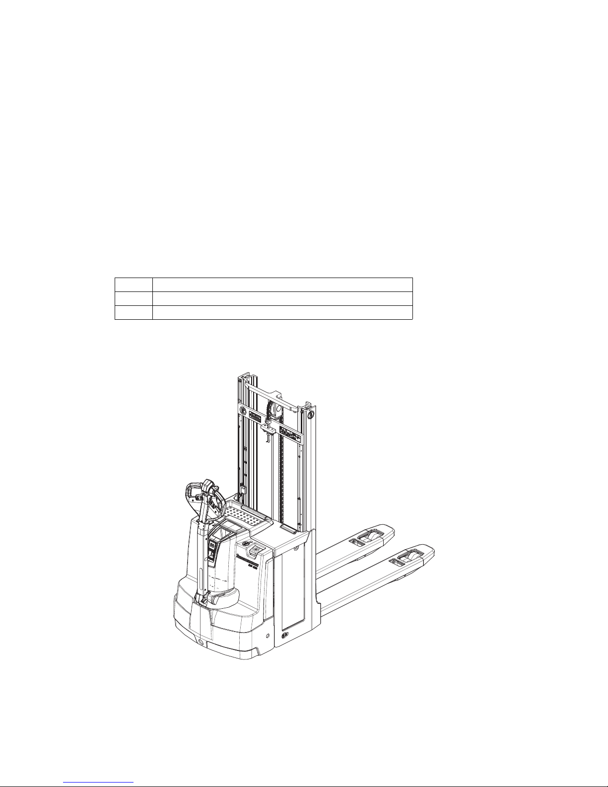
The EJD 220 is a three-wheel, electric tiller-operated pallet truck with a steered drive
wheel and coupling unit
It is designed to be used on level surfaces for lifting, stacking and transporting goods.
For transportation, two pallets can be stacked on top of each other. Open bottom
pallets or roll cages can be lifted.
1.1 Truck models and rated capacity
The rated capacity depends on the model. The rated capacity can be derived from
the model name.
The rated capacity is not generally the same as the permissible capacity. The
capacity can be found on the capacity plate attached to the truck.
EJD220
EJD Model name
2Series
20 Rated capacity x 100 kg
Page 17
11.14 E N
16
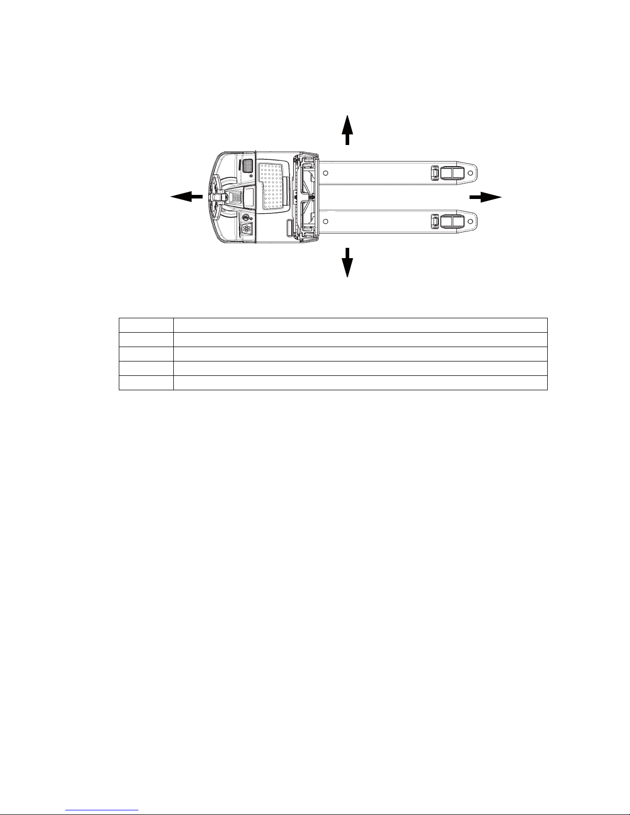
2 Travel direction definition
The following determinations have been made for travel direction specification:
Item Travel direction
1 Left
2 Drive direction
3 Load direction
4 Right
1
2
3
4
Page 18
17
11.14 E N
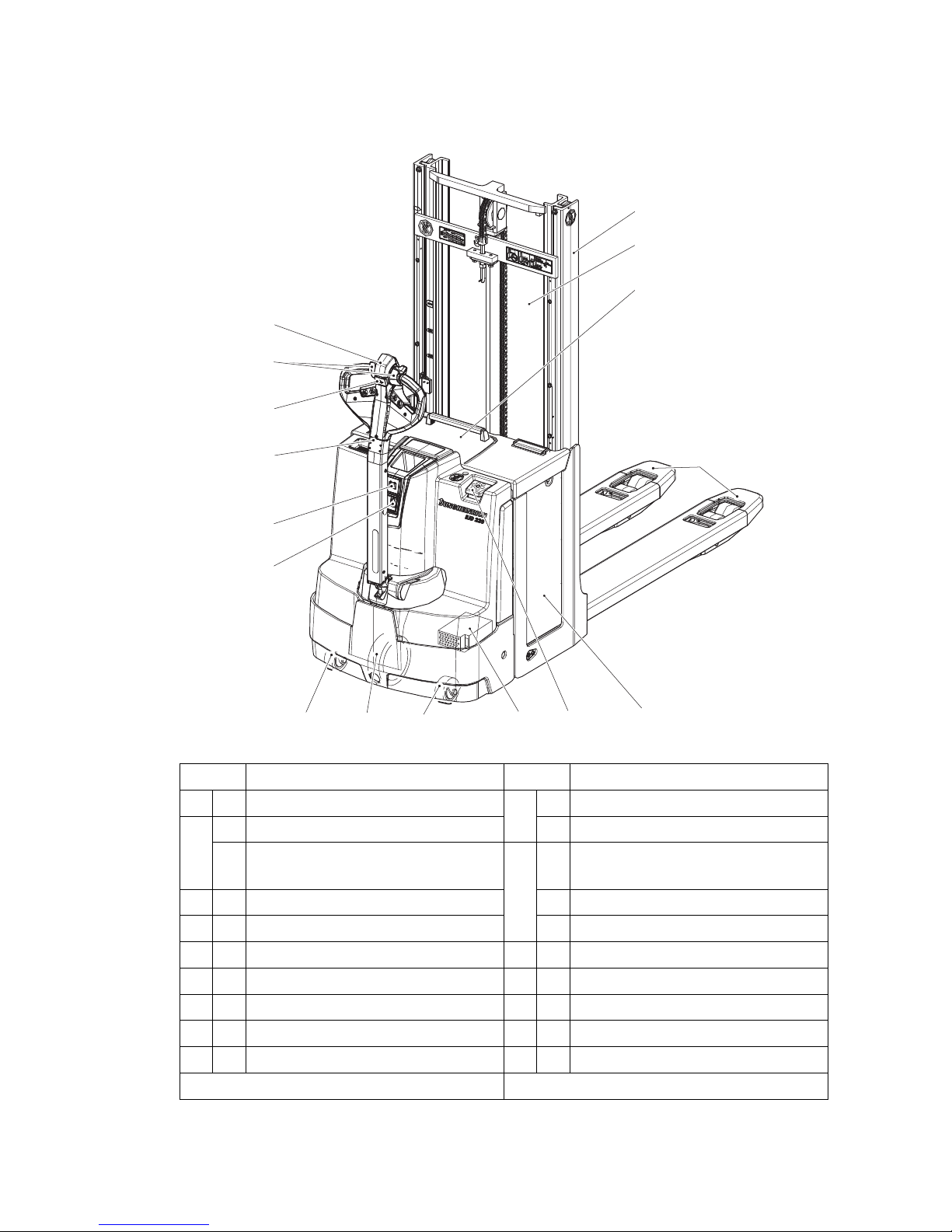
3 Assemblies and Functional Description
3.1 Assembly Overview
Item Component Item Component
5 t Mast 13 t Charge display
6 t Mast protection pane o CanDis
o Protective grille
(for cold store operation)
14 t Key switch
7 t Battery cover o CanCode
8 t Collision safety switch o ISM Access Module
9 t Travel switch 15 t Support wheel
10 t Slow travel button 16 t Drive wheel
11 t Load handler 17 o On-board charger
12 t Tiller 18 t Battery
19 t Emergency Disconnect switch
t = Standard version o = Option
15
5
7
1918
11
16 17
6
14
13
12
10
8
9
15
Page 19

11.14 E N
18
3.2 Functional Description
Safety mechanisms
An enclosed, smooth truck geometry with rounded edges ensures safe handling of
the truck. The wheels are surrounded by a solid skirt.
The long tiller provides a maximum safety distance to the truck. When it is released
and in hazardous situations, a gas strut forces the tiller up into the brake position. The
collision safety switch in the tiller head responds to body contact, the travel direction
changes and the truck moves away from the operator.
Activating the Emergency Disconnect switch rapidly cuts out all electrical functions in
hazardous situations.
The mast protection pane or grille (o) protect the operator from moving mast parts
and the load.
Emergency Stop safety feature
The Emergency Stop is activated by the traction controller. Each time the truck is
switched on the system performed a self diagnosis. If an error is detected, the truck
automatically brakes to a halt. Control displays in the CanDis display instrument (o)
indicate the Emergency Stop.
CAUTION!
The truck brakes automatically
If the truck detects that signals which are required have not been received, or if it
detects an error, the system reacts by triggering an emergency stop, either by braking
the truck to a halt or until a valid signal status has been reached.
XRemain at a suitable distance from the truck during operation.
Page 20

19
11.14 E N
Hydraulic System
Lifting and lowering are activated via the lift and lower buttons. Pressing the lifting
button starts the pump unit, supplying hydraulic oil from the oil reservoir to the lift
cylinder. With the two-stage Duplex mast (ZZ) (o) or three-stage telescopic mast
(DZ) (o) a short, centre-mounted free lift cylinder initially lifts the load handler (free
lift) without changing the overall height of the truck.
Drive system
A fixed AC three-phase motor actuates the drive wheel via a bevel spur gearbox. The
electronic traction controller ensures smooth drive-motor-speed control and hence
smooth starting, powerful acceleration and electrically controlled braking with energy
regeneration. The driver can choose from 3 travel programs depending on the load
and the environment: from high-performance to energy-saving.
Tiller
The driver steers with an ergonomic tiller. All travel and lift operations can be
performed sensitively without having to reach. The tiller has a steer angle of 180°.
Electrical system
The truck has an electronic traction controller. The operating voltage of the truck's
electrical system is 24 volts.
Controls and displays
Ergonomic controls ensure fatigue-free operation for sensitive application of the
travel and hydraulic operations. The battery discharge indicator shows the available
battery capacity. The CanDis display (o) shows information which is important for the
operator such as travel program, service hours, battery capacity and event
messages.
Page 21

11.14 E N
20
Mast
The high strength steel sections are narrow, enabling excellent visibility of the load
handler. The lift rails and the load handler run on permanently-lubricated and hence
maintenance-free angled rollers.
Load backrest (
o
)
A load backrest is recommended as an additional protective mechanism to move low
or small item loads above the mast protection frame or grille (o). The load backrest
is mounted on the load handler and protects the operator and truck against falling
loads.
Z The extended mast height (h4) increases according to the load backrest mounted
on the load handler.
WARNING!
Risk of injury from falling loads
Low or small item loads moved above the mast protection pane or grille (o) and
protruding over the load backrest can fall, endangering the operator and truck.
XSecure low or small item loads protruding over the load backrest, e.g. by wrapping
them in film.
3.2.1 Hourmeter
Z Prepare the truck for operation, see "Preparing the truck for operation" on page 61
or see "CanCode Keypad (o)" on page 94.
Service hours are counted while the truck is operational and one of the following
controls is applied:
– Tiller in travel zone "F", see "Travel" on page 69.
– "Slow travel button", see page 72.
– "Lift" button, see page 76.
– "Lower" button, see page 77.
o
Page 22

21
11.14 E N
4 Technical Specifications
Z The technical specifications comply with the German "Industrial Truck Data Sheet"
Guidelines.
Technical modifications and additions reserved.
4.1 Performance data
EJD 220
Q Rated capacity 2000 kg
Capacity for mast lift
1
1. Depends on lift height.
1000 kg
Capacity for support arm lift 2000 kg
D Load centre distance 600 mm
Travel speed
with / without rated load
6.0 / 6.0 km/h
Lift speed
with / without rated load
0.14 / 0.25 m/s
Lowering speed
with / without rated load
0.40 / 0.40 m/s
Max. gradeability (5 min.)
with / without rated load
9 / 15 %
Drive motor,
Output S2 60 min
1.6 kW
Lift motor,
Output S3 10%
2.0 kW
Page 23
11.14 E N
22
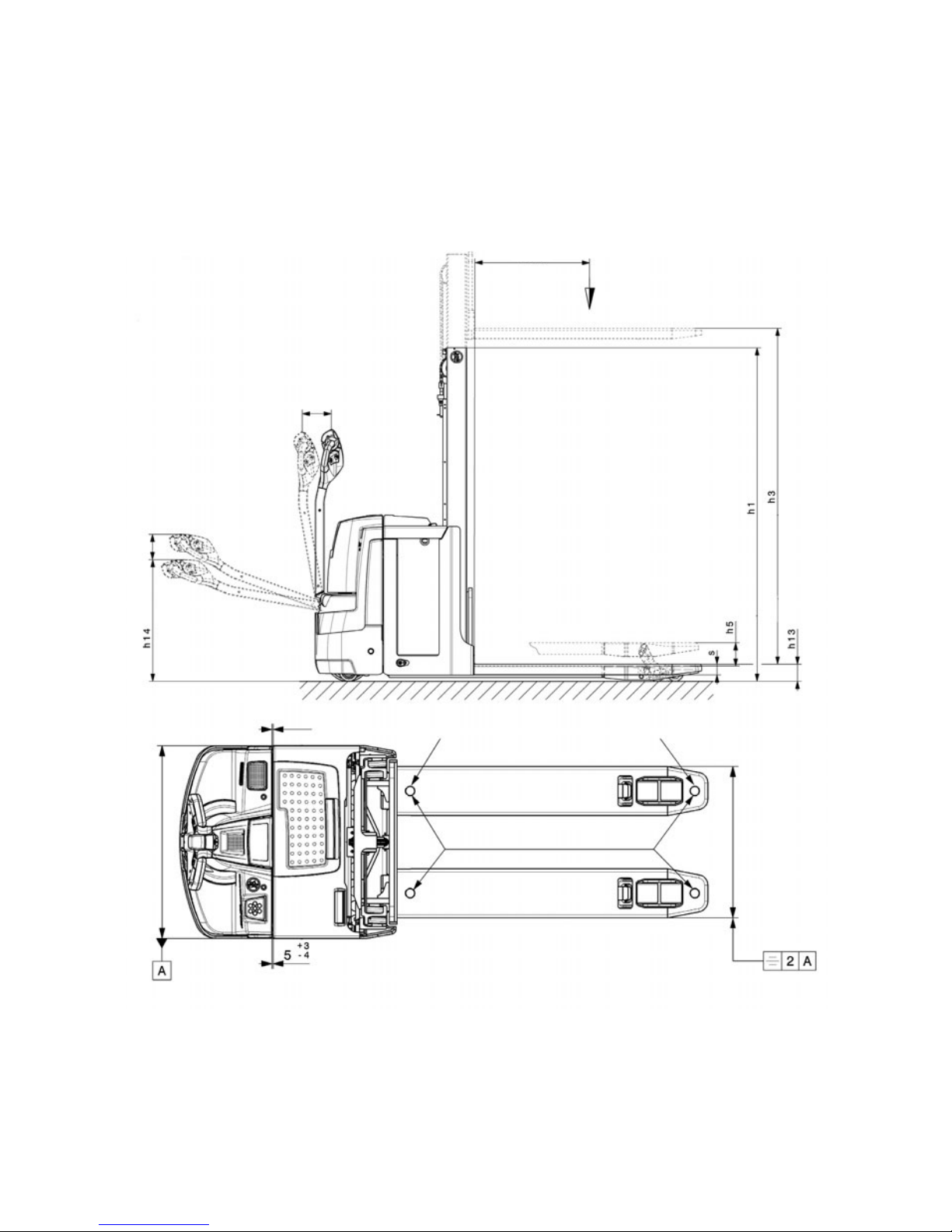
4.2 Dimensions
D
Q
Page 24

23
11.14 E N
Model EJD 220
x Load distance 1) 957 mm
y Wheel base 1) 4) 1617 mm
h3 Lift 5) 1660 mm
h5 Initial lift 122 mm
h13 Lowered height 90 mm
h14 Tiller height in the travel position min./max. 711 / 1320 mm
L1 Length 4) 2022 mm
L2 Fork length including fork shank 4) 832 mm
b1/2 Overall width (drive) 726 mm
b5 Width across forks 570 mm
s/e/l Fork dimensions 56 / 185 / 1190 mm
b10 Track width, front 508 mm
b11 Track width, rear 385 mm
m2 Ground clearance, centre wheelbase 20 mm
Ast Aisle width
with pallet 1000x12000 traverse 2) 4)
2233 mm
Ast Aisle width
with pallet 800x1200 longit. 3) 4)
2243 mm
Wa Turning radius 1) 4) 1800 mm
1) Load section lowered + 48 mm
2) Load section lowered + 48 mm; diagonal in accordance with VDI + 369 mm
3) Load section lowered + 48 mm; diagonal in accordance with VDI + 225 mm
4) Battery compartment M version / battery compartment L version = version M + 72
mm
5) Values for standard mast 166ZT
Page 25

11.14 E N
24
4.3 Weights
4.4 Tyre type
Net weight incl. battery M/L 937 / 1032 kg
Axle loading, laden
front/rear + battery
1120 / 1825
1160 / 1872
kg
Axle loading, unladen
front/rear + battery
665 / 280
732 /300
kg
Battery weight 220 / 288 kg
Tyre size, drive 230 x 65 mm
Load section tyre size (single / tandem) 85 x 95 / 85 x 75 mm
Castor wheel 100 x 40 mm
Wheels, number front/rear
(x = driven)
1x +2 /2 or 4 mm
Page 26

25
11.14 E N
4.5 EN norms
Noise emission level
– EJD 220: 70 dB(A)
in accordance with EN 12053 as harmonised with ISO 4871.
Z The noise emission level is calculated in accordance with standard procedures and
takes into account the noise level when travelling, lifting and when idle. The noise
level is measured at the level of the driver's ear.
Electromagnetic compatibility (EMC)
The manufacturer confirms that the truck adheres to the limits for electromagnetic
emissions and resistance as well as the static electricity discharge test in accordance
with EN 12895 as well as the standardised instructions contained therein.
Z No changes to electric or electronic components or their arrangement may be
made without the written agreement of the manufacturer.
WARNING!
Medical equipment can be damaged by non-ionised radiation
Electrical equipment on the truck emitting non-ionised radiation (e.g. wireless data
transmission) can affect operators' medical equipment (pacemakers, hearing aids
etc.) and result in malfunctions. Consult a doctor or the manufacturer of the medical
equipment to clarify whether it can be used near the industrial truck.
Page 27

11.14 E N
26
4.6 Conditions of use
Ambient temperature
– operating at 5°C to 40°C
Z Special equipment and authorisation are required if the truck is to be used
continually in conditions of extreme temperature or condensing air humidity
fluctuations.
4.7 Electrical Requirements
The manufacturer certifies compliance with the requirements for the design and
manufacture of electrical equipment, according to EN 1175 "Industrial Truck Safety Electrical Requirements", provided the truck is used according to its purpose.
Page 28
27
11.14 E N
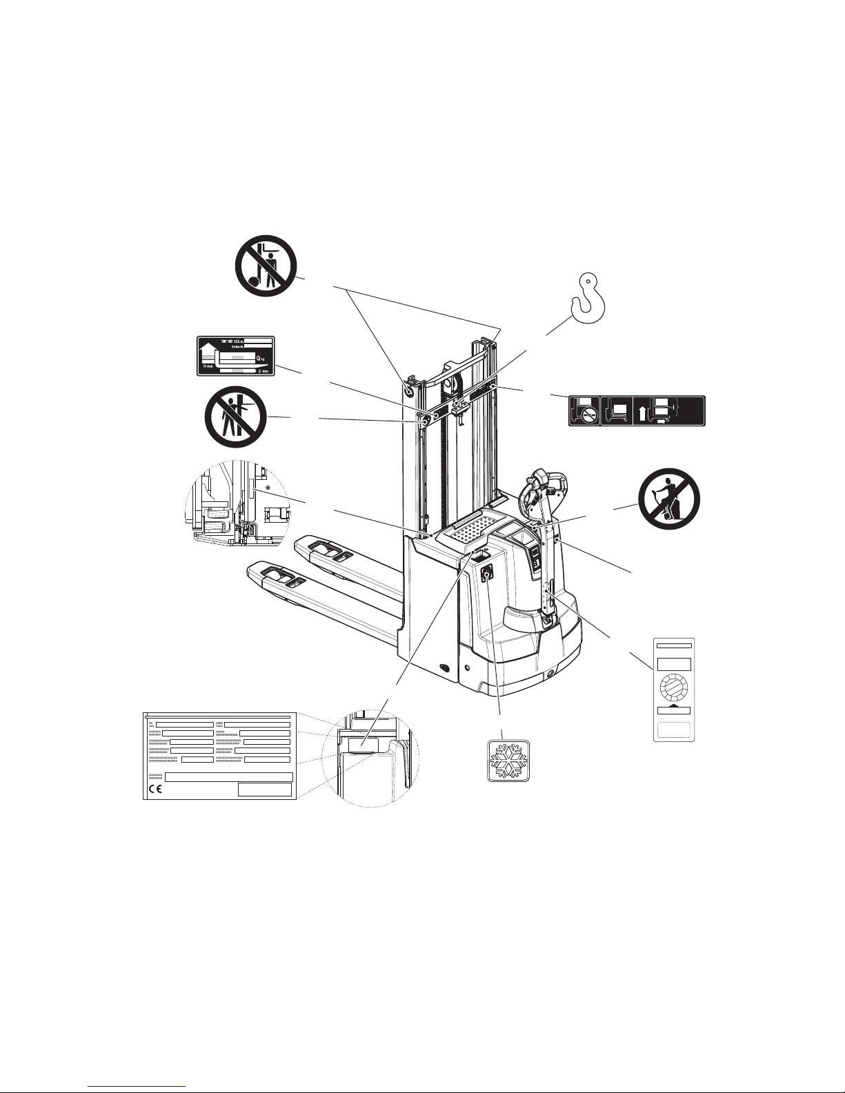
5 Identification Points and Data Plates
Z Warnings and notices such as capacity charts, strap points and data plates must
be legible at all times. Replace if necessary.
5.1 Indication Points
XXXXXXXX
kg
Q max
XXXX
Q max
Dmm
Hmm
kg
XXXX
1600
XXX
max
2000 kg
max
100 mm
X.XXXX.XX.XX
20
24
26
22
23
29
25
28
27
21
30
Page 29

11.14 E N
28
Item Component
20 Warning: “Do not step under the load handler”
21 Attachment points for lifting by crane (with ZZ mast in the middle)
22 Capacity plate
23 Capacity Qmax
24 Warning: "Do not reach through the mast"
25 Serial number
26 Warning: “No passengers”
27 Model name
28 Test plaque
29 Data plate
30 Cold store truck reference
Page 30
29
11.14 E N
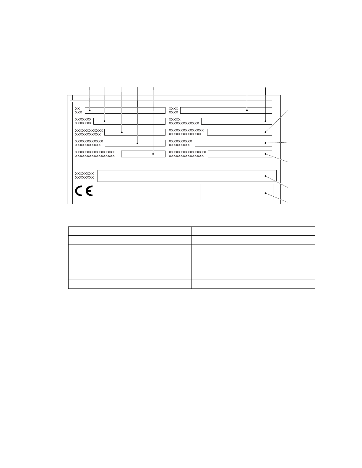
5.2 Data plate
Z The illustration shows the standard version for EU member states. The data plate
may differ in other countries.
Z For queries regarding the truck or ordering spare parts always quote the truck serial
number (32).
31 32 3433 35
42
38
41
40
39
3736
Item Description Item Description
31 Type 37 Year of manufacture
32 Serial number 38 Load centre (mm)
33 Rated capacity (kg) 39 Output
34 Battery voltage (V) 40 Min./max. battery weight (kg)
35 Net weight w.o. battery (kg) 41 Manufacturer
36 Option 42 Manufacturer’s logo
Page 31

11.14 E N
30
5.3 Truck capacity plate
Previous capacity plate
Current capacity plate
The rating plate (22) indicates the maximum capacity Q (in kg) for a given load centre
C (in mm) and corresponding lift height H (in mm) for the truck with a horizontal load.
Example of how to calculate the maximum capacity:
At a load centre distance C1 and a lift height H1, the maximum load capacity is Q1
The arrow shaped markings on the outer mast (43) and
on the inner mast (44) indicate to the operator when the
height limits specified on the capacity plate have been
exceeded.
-Nr.
Serien-Nr.
D mm
H
mm
Q
kg
Q1
D1
H1
22
SERIAL NO.
kg
mm
mm
D1
H1
Q1
22
43 44
Page 32

31
11.14 E N
5.4 Wind loads
Wind forces can affect the stability of a truck when lifting, lowering and transporting
loads with large surface areas.
Light loads must be especially secured when they are subjected to wind forces. This
will prevent the load from sliding or falling.
Stop the truck in both cases.
Page 33

11.14 E N
32
5.5 Double Decker Mode Capacity Plate
The double decker mode capacity plate (23) indicates the capacity Q kg of the truck
while travelling:
CAUTION!
Risk to operational stability
In order not to jeopardize the operational stability, pay attention to the weight when
transporting two pallets so that the truck does not tip over.
XIn order not to jeopardize the operational stability, the heavier pallet should always
be transported underneath.
A= No transporting with a raised load.
B= Max. capacity for horizontal transporting XXX kg with raised support arms without
mast lift.
C= Double decker mode:
Max. lift height YYY mm.
Max. capacity for high level lifting according ZZZ.
Max. capacity for both high and low level lifting XXX kg.
kg
Q max
XXX
Q max
Cmm
Hmm
kg
ZZZ
YYY
DDD
max
XXX kg
max
100 mm
A
B
C
23
Page 34

33
11.14 E N
C Transport and Commissioning
1 Lifting by crane
WARNING!
All persons involved in loading by crane must be trained
Incorrect crane loading procedures due to untrained personnel can cause the truck
to fall. There is a risk of injury to personnel and a risk of material damage to the truck.
XLoading must only be performed by specialist personnel trained for this purpose.
The specialist personnel must be instructed in securing loads on road vehicles and
handling load securing devices. In each case correct measurements must be taken
and appropriate safety measures applied.
WARNING!
Incorrect lifting by crane can result in accidents
Improper use or use of unsuitable lifting gear and can cause the truck to fall when
being lifted by crane.
Prevent the truck from hitting other objects during lifting, and avoid uncontrolled
movements. If necessary, secure the truck with guide ropes.
XThe truck should only be loaded by personnel trained in the use of lifting slings and
tools.
XWear personal protective equipment (e. g. safety shoes, safety helmet, hi-vis
jacket, protective gloves, etc.) when loading by crane.
XDo not stand under suspended loads.
XDo not enter or stand in a hazardous area.
XAlways use lifting gear with sufficient capacity (for truck weight see truck rating
plate).
XAlways attach the crane lifting gear to the prescribed strap points and prevent them
from slipping.
XUse the lifting slings only in the prescribed loading direction.
XCrane slings should be fastened in such a way that they do not come into contact
with any attachments when lifting.
Page 35

11.14 E N
34
Lifting the truck by crane
Requirements
– Park the truck securely, see "Parking
the truck securely" on page 63.
– Remove any mast guards.
Tools and Material Required
– Lifting gear
– Crane lifting gear
Procedure
• Secure the lifting slings to the strap
points (21).
The truck can now be lifted by crane.
21
Page 36

35
11.14 E N
2 Transport
WARNING!
Accidental movement during transport
Improper fastening of the truck and mast during transport can result in serious
accidents.
XLoading must only be performed by specialist personnel trained for this purpose.
The specialist personnel must be instructed in securing loads on road vehicles and
handling load securing devices. In each case correct measurements must be taken
and appropriate safety measures applied.
XThe truck must be securely fastened when transported on a lorry or a trailer.
XThe lorry or trailer must have fastening rings.
XUse wedges to prevent the truck from moving.
XUse only fastening belts with sufficient strength.
XUse non-slip materials to securing the load aids (pallet, wedges, ...) e. g. non-slip
mats.
Securing the industrial truck for
transport
Requirements
– Load the truck.
– Park the truck securely, see "Parking
the truck securely" on page 63.
Tools and Material Required
– Lashing straps
Procedure
• Attach the lashing straps (45) to the
industrial truck and the transport
vehicle and tension sufficiently.
The truck can now be transported.
45
Page 37

11.14 E N
36
3 Using the Truck for the First Time
WARNING!
The use of unsuitable energy sources can be hazardous
Rectified AC current will damage the assemblies (controllers, sensors, motors etc.)
of the electronic system.
Unsuitable cable connections (too long, insufficient wire cross-section) to the battery
(tow cables) can overheat, setting the truck and battery on fire.
XThe truck must only be operated with battery current.
XCable connections to the battery (tow leads) must be less than 6 m long and have
a minimum cross-section of 50 mm².
Procedure
• Check the equipment is complete.
• If necessary, install the battery, see "Battery removal and installation" on page 49.
• Charge the battery, see "Charging the battery" on page 41.
The truck can now be started, see "Preparing the Truck for Operation" on page 60.
NOTE
Do not lift loads if the truck is operated via a tow lead with an external battery.
NOTE
Cold store trucks
XTrucks designed for use in cold stores have a cold store hydraulic oil and a
protective frame instead of a mast guard on the mast.
XIf a truck with cold store oil is used outside the cold store, the lowering speeds may
increase.
Wheel flattening
If the truck has been parked for a long period, the wheel surfaces may tend to flatten.
This flattening has a negative effect on the safety and stability of the truck. Once the
truck has covered a certain distance, the flattening will disappear.
Page 38

37
11.14 E N
D Battery - Servicing, Recharging,
Replacement
1 Safety Regulations Governing the Handling of Lead-Acid
Batteries
Maintenance personnel
Batteries may only be charged, serviced or replaced by trained personnel. These
operating instructions and the manufacturer’s instructions concerning batteries and
charging stations must be observed when carrying out the work.
Fire Protection
Do not smoke and avoid naked flames when handling batteries. Wherever an
industrial truck is parked for charging there must be no inflammable material or
consumables capable of creating sparks within a minimum distance of 2 m from the
truck. The room must be ventilated. Fire protection equipment must be available.
CAUTION!
The use of unsuitable fire protection equipment can result in scalding
Extinguishing fires with water can cause a reaction with the battery acid. This can
result in scalding from the acid.
XUse powder extinguishers.
XNever extinguish a burning battery with water.
Battery maintenance
The battery cell covers must be kept dry and clean. The terminals and cable shoes
must be clean, secure and have a light coating of dielectric grease.
CAUTION!
Short circuits can cause fires
Damaged cables can cause a short circuit, setting the truck and the battery on fire.
XBefore closing the battery cover make sure that the battery cables cannot be
damaged.
Battery disposal
Batteries may only be disposed of in accordance with national environmental
protection regulations or disposal laws. The manufacturer’s disposal instructions
must be observed.
Page 39

11.14 E N
38
WARNING!
Batteries can be hazardous
Batteries contain an acid solution which is poisonous and corrosive. Avoid contact
with battery acid at all times.
XDispose of used battery acid in accordance with regulations.
XAlways wear protective clothing and goggles when working with batteries.
XDo not let battery acid come into contact with skin, clothing or eyes. If necessary,
rinse with plenty of clean water.
XIn the event of physical damage (e.g. skin or eye contact with battery acid) call for
a doctor immediately.
XSpilled battery acid should be neutralised immediately with plenty of water.
XOnly batteries with a sealed battery container may be used.
XFollow national guidelines and legislation.
WARNING!
Unsuitable batteries that have not been approved by Jungheinrich for the truck
can be hazardous
The design, weight and dimensions of the battery have a considerable effect on the
operational safety of the truck, in particular its stability and capacity. The use of
unsuitable batteries that have not been approved for the truck by Jungheinrich, can
lead to a deterioration of the braking characteristics of the truck during energy
recovery, causing considerable damage to the electric controller and resulting in
serious danger to the health and safety of individuals.
XOnly Jungheinrich-approved batteries may be used on the truck.
XBattery equipment may only be replaced with the agreement of Jungheinrich.
XWhen replacing/installing the battery make sure the battery is securely located in
the battery compartment of the truck.
XDo not use batteries that have not been approved by the manufacturer.
Park the truck securely before carrying out any work on the batteries (see "Parking
the truck securely" on page 63).
Page 40

39
11.14 E N
2 Battery types
Depending on the model, the truck will be supplied with different battery types. The
following table shows which combinations are included as standard:
The battery weights can be taken from the battery data plate. Batteries with non
insulated terminals must be covered with a non slip insulating mat.
Battery type Capacity (Ah) Min. weight
(kg)
Max. dimensions
(mm)
24 volt battery 2 PzV 200 204 624X212X628
24 volt battery 2 PzS 250 204 624X212X628
24 volt battery 2 PzS 375 273 624X284X628
24 volt battery 3 PzV 300 273 624X284X628
24 volt battery 3 PzS 375 Lib. Silver 273 624X284X628
24 volt battery 2 PzS 250 Lib. Silver 204 624X212X628
24 volt battery 2 PzM 250 204 624X212X628
24 volt battery 3 PzM 375 273 624X284X628
24 volt battery 2 PzV 220 204 624X212X628
24 volt battery 3 PzV 330 273 624X284X686
24 volt battery XFC 158 204 624X212X628
24 volt battery XFC 316 273 624X284X628
Page 41

11.14 E N
40
3 Exposing the battery
WARNING!
An unsecured truck can cause accidents
Parking the truck on an incline or with a raised load handler is dangerous and is
strictly prohibited.
XPark the truck on a level surface. In special cases the truck may need to be secured
with wedges.
XFully lower the load handler.
XSelect a place to park where no other people are at risk of injury from the lowered
load handler.
XIf the brakes are not working, place wedges underneath the wheels of the truck to
prevent it from moving.
CAUTION!
A closing battery panel can pose a trapping hazard
If the battery cover is not opened fully, it can suddenly close on its own and cause
bruising. The battery cover is only properly opened at an angle greater than 90°. It is
then held by gravity.
XOpen the battery cover as far as the stop.
Requirements
– Park the truck on a level surface.
– Park the truck securely, see "Parking the
truck securely" on page 63.
Procedure
• Open the battery panel (7).
• Where necessary remove the insulating
mat from the battery.
The battery is now exposed.
7
Page 42

41
11.14 E N
4 Charging the battery
WARNING!
The gases produced during charging can cause explosions
The battery gives off a mixture of oxygen and hydrogen (electrolytic gas) during
charging. Gassing is a chemical process. This gas mixture is highly explosive and
must not be ignited.
XSwitch the charging station and truck off first before connecting/disconnecting the
charging cable of the battery charging station to/from the battery connector.
XThe charger must match the battery in terms of voltage, charge capacity and
battery type.
XBefore charging, check all cables and plug connections for visible signs of damage.
XVentilate the room in which the truck is being charged.
XThe battery cover must be open and the battery cell surfaces must be exposed
during charging to ensure adequate ventilation.
XDo not smoke and avoid naked flames when handling batteries.
XWherever an industrial truck is parked for charging there must be no inflammable
material or consumables capable of creating sparks within a minimum distance of
2 m from the truck.
XFire-control equipment must be available.
XDo not place any metallic objects on the battery.
XAlways follow the safety regulations of the battery and charger station
manufacturers.
NOTE
Battery damage
The battery, charger (charge characteristics) and battery parameters must match
each other, otherwise damage may result.
Page 43

11.14 E N
42
4.1 Charging the battery with a stationary charger
Charging the battery
Requirements
– Expose the battery, see "Exposing the battery" on page 40.
Procedure
• Disconnect the battery connector (46) from the truck connector.
• Connect the battery connector (46) to the charging cable (47) of the stationary
charger.
• Start charging in accordance with the charger operating instructions.
The battery is charging.
Completing battery charging, restoring the truck to operation
NOTE
If charging has been interrupted, the full battery capacity will not be available.
Requirements
– The battery is fully charged.
Procedure
• Complete charging in accordance with the charger operating instructions.
• Disconnect the battery connector (46) from the charging cable (47) of the stationary
charger.
• Attach the battery connector (46) to the industrial truck.
The truck is now ready for operation.
46
47
Page 44

43
11.14 E N
4.2 Charging the battery with an on-board charger (o)
DANGER!
Risk of electric shock and fire
Damaged and unsuitable cables can cause electric shocks and can overheat,
resulting in fires.
XAlways use mains cables with a maximum length of 30 m.
Local regulations must be observed.
XUnwind the cable reel fully when using it.
XAlways use original manufacturer’s mains cables.
XInsulation safety, acid and caustic ratings must comply with the manufacturer's
mains lead.
XThe charging connector must be dry and clean when used.
NOTE
Improper use of the on-board charger can cause material damage
The on-board charger consisting of a battery charger and battery controller must not
be opened. If faulty, contact the manufacturer’s customer service department.
XThe charger must only be used for batteries supplied by Jungheinrich or other
approved batteries provided it has been adapted by the manufacturer's customer
service department.
XBatteries must never be swapped from truck to truck.
XDo not connect the battery to two chargers simultaneously.
Page 45

11.14 E N
44
4.2.1 Setting the charging characteristics (ELG 2430)
Z The factory setting for trucks without a battery is the 0 position. A battery discharge
indicator, a charge/discharge indicator, a CanDis or a bipolar LED can be attached
to the connector (49).
CAUTION!
XRemove the mains connector before setting the respective charging curve.
Set the charging characteristic
Requirements
– Battery connected.
Procedure
• Turn the setting switch (48) on the charger right to adapt the charging curve to the
battery being used.
• The validity of the new setting is acknowledged by the flashing of the green LED
and the setting takes immediate effect.
The charging characteristic is now set.
48
49
Page 46

45
11.14 E N
NOTE
XAll other switch positions (48) block the charger, and the battery is not charged.
XFor PzM batteries with a capacity of less than 180 Ah set characteristic 1, beyond
180 Ah set characteristic 5.
XWith PzS 200-300 Ah wet cell batteries both characteristic curves 1 and 5 can be
used. Characteristic 5 achieves a faster charge.
XWhen the battery is connected this allows you to adjust via the charger: If the switch
position is valid the green LED flashes according to the position set; if the switch
position is invalid the red LED flashes.
Flashing sequence / charging curve assignment (ELG 2430)
Flashing sequence Selected charging curves (characteristics)
0 Truck without battery
1
Wet cell battery: PzS with 100 - 300 Ah
Wet cell battery: PzM with 100 - 179 Ah
2 Maintenance-free: PzV with 100 - 149 Ah
3 Maintenance-free: PzV with 150 - 199 Ah
4 Maintenance-free: PzV with 200 - 330 Ah
5
Wet cell battery: PzS with pulse characteristic 200 400 Ah
Wet cell battery: PzM with pulse characteristic 180 400 Ah
6 Jungheinrich 100 - 300 Ah
Page 47

11.14 E N
46
4.2.2 Charging the battery
Starting to charge with the on-board charger
– ELG mains connection
Mains supply: 230 V / 110 V (+10/-15%)
Mains frequency: 50 Hz / 60 Hz
The mains cable and mains connector (51) of the charger are contained in the battery
compartment with their storage compartment (50) .
Charging the battery
Requirements
– Park the truck securely, see "Parking the truck
securely" on page 63.
– Expose the battery, see "Exposing the battery" on
page 40.
– Correct charging program set on charger.
Procedure
• Remove any insulating mats from the battery.
• The battery connector must remain plugged.
• Attach the mains connector (51) to a mains socket.
• Pull the Emergency Disconnect switch up.
The flashing LED indicates the charge status or a fault (for flashing codes see “LED
Display” table).
The battery is now charged.
Z When the mains connector (51) is attached to the mains, all the truck’s electrical
functions are disconnected (electric immobilizer). The truck cannot be operated.
50
51
Page 48

47
11.14 E N
Completing battery charging, restoring the truck to operation
NOTE
If charging has been interrupted, the full battery capacity will not be available.
Requirements
– The battery is fully charged.
Procedure
• Remove the mains connector (51) from the mains socket and store it along with the
cable in the storage compartment (50).
• If applicable, place the existing insulating mats back over the battery.
• Close the battery panel securely.
The truck is now ready for operation.
CAUTION!
Damaged mains cables can be hazardous
XDo not trap the mains cable when closing the battery panel.
Charging times
The duration of charge depends on the battery capacity.
Z Charging continues automatically after a mains failure. Charging can be interrupted
by removing the mains connector and continued as partial charging.
Page 49

11.14 E N
48
LED display (52)
Compensation charge
The compensation charge starts automatically when charging is complete.
Partial charging
The charger is designed to automatically adapt to partially charged batteries. This
keeps battery wear to a minimum.
Green LED (charge status)
Lit Charging complete, battery full.
(Charge interval, float or
compensation charge).
Flashes slowly Charging.
Rapid flash Display at beginning of charge or
after setting a new characteristic
curve. Number of flash pulses
corresponds to the characteristic
curve set.
Red LED (fault)
Lit Overtemperature. Charging is
interrupted.
Flashes slowly Safety charging time exceeded.
Charging is cancelled.
Mains must be disconnected for
charging to restart.
Rapid flash Invalid characteristic curve
setting.
52
Page 50

49
11.14 E N
5 Battery removal and installation
WARNING!
Accident risk during battery removal and installation
Due to the battery weight and acid there is a risk of trapping or scalding when the
battery is removed and installed.
XNote the "Safety regulations for handling acid batteries" section in this chapter.
XWear safety shoes when removing and installing the battery.
XUse only batteries with insulated cells and terminal connectors.
XPark the truck on a level surface to prevent the battery from sliding out.
XMake sure the crane slings have sufficient capacity to replace the battery.
XUse only approved battery replacement devices (battery roller stand, replacement
trolley etc.).
XMake sure the battery is securely located in the truck's battery compartment.
CAUTION!
Trapping hazard
There is a risk of trapping when you close the battery cover.
XMake sure there is nothing between the battery cover and the truck when you close
the battery cover.
Page 51

11.14 E N
50
5.1 Lateral battery removal
CAUTION!
Trapping hazard
Trapping hazard when removing and installing the battery.
XWhen removing and installing the battery do not put your hands between the
battery and the chassis.
Removing the battery
Requirements
– Truck parked securely, see "Parking
the truck securely" on page 63
– The battery is exposed, see
"Exposing the battery" on page 40
Procedure
• Disconnect the battery connector
from the truck connector.
• Lift up the battery lock (53) as far as
the stop.
• Pull the battery retaining lever /
ejector (54) up and move the battery
to the side.
• Pull the battery out from the side.
The battery has now been removed.
Battery installation
NOTE
XMake sure the battery is installed and connected correctly.
XPlace the battery cable on the tray so that it cannot be severed when the battery is
inserted.
Procedure
• Insert the battery in the truck.
• Push the battery as far as the stop in the battery compartment.
• Raise the battery retaining lever (54) and pull the battery fully into the battery
compartment.
• Turn the battery lock (53) down as far as the stop.
53
54
Page 52

51
11.14 E N
CAUTION!
Unsecured battery
Unsecured batteries can slide out of the battery tray.
XAfter installing the battery make sure the battery lock (53) is in place to prevent it
from sliding out.
Z After installing the battery again, check all cables and plug connections for visible
signs of damage.
53
54
Page 53

11.14 E N
52
Page 54

53
11.14 E N
E Operation
1 Safety Regulations for the Operation of the
Forklift Truck
Driver authorisation
The truck may only be used by suitably trained personnel, who have demonstrated to
the proprietor or his representative that they can drive and handle loads and have
been authorised to operate the truck by the proprietor or his representative.
Operator’s rights, responsibilities and rules of conduct
The driver must be informed of his duties and responsibilities and be instructed in the
operation of the truck and shall be familiar with the operating instructions. Safety
shoes must be worn on pedestrian-operated trucks.
Unauthorised use of truck
The operator is responsible for the truck during the time it is in use. The operator must
prevent unauthorised persons from driving or operating the truck. Do not carry
passengers or lift other people.
Damage and faults
The supervisor must be informed immediately of any damage or faults to the truck or
attachment. Trucks which are unsafe for operation (e.g. wheel or brake problems)
must not be used until they have been rectified.
Repairs
The operator must not carry out any repairs or alterations to the truck without
authorisation and the necessary training to do so. The operator must never disable or
adjust safety mechanisms or switches.
Page 55

11.14 E N
54
Hazardous area
WARNING!
Risk of accidents/injury in the hazardous area of the truck
A hazardous area is defined as the area in which people are at risk due to travel or
lifting operations of the truck, its load handler or the load. This also includes the area
within reach of falling loads or lowering/falling operating equipment.
XInstruct unauthorised persons to leave the hazardous area.
XIn case of danger to third parties, give a warning signal in good time.
XIf unauthorised persons are still within the hazardous area, stop the truck
immediately.
Safety devices, warning signs and warning instructions
Safety devices, warning signs (see "Identification Points and Data Plates" on
page 27) and warning instructions in the present operating instructions must be
strictly observed.
WARNING!
Removing or disabling safety devices can cause accidents
Removing or disabling safety devices such as the Emergency Disconnect switch, key
switch, buttons, horn, strobe lights, mast protection pane, mast grille, sensors, panels
etc. can result in accidents and injury.
XReport any defects immediately to your supervisor.
XMark defective truck and take out of service.
XDo not return the industrial truck to service until you have identified and rectified the
fault.
Page 56

55
11.14 E N
2 Displays and Controls
oo
t
14, 63
60
19
17
10
13, 62
12
5857
59
5655
60
61
58 57
56 55
60
59
60
61
Page 57

11.14 E N
56
Item Control /Display EJD 220 Function
10 Slow travel button t Pressing the slow travel button
reduces the travel speed and
acceleration. If the tiller is in the
brake zone, pressing this button
overrides the braking function and
the truck can be operated at slow
speed.
12 Tiller t Used for steering and braking.
13 Charge / discharge
indicator
t Shows the charge/discharge status
of the battery.
14 CanCode o Replaces the key switch
– Entering the code activates the
truck
– Travel program selection
– Code setting
– Parameter setting
ISM o Replaces the key switch
– Activates the truck via a card /
transponder
– Displays readiness for operation
– Operational data logging
– Data exchange with card /
transponder
17 On-board charger (with
safety switch)
o Charges the battery by inserting the
mains connector into a mains socket.
19 Emergency disconnect
switch
t Disconnects the battery supply
– All electric functions are
deactivated and the truck
decelerates
55 Wheel arm lift button t Lifts the wheel arms at a constant
speed.
56 Fork lift button t Raises the forks. The lowering speed
can be infinitely controlled by the
stroke of the button (8 mm).
57 Wheel arm lower button t Lowers the wheel arms at a constant
speed.
58 Fork lowering switch t Lowers the forks. The lowering
speed can be infinitely controlled by
the stroke of the button (8 mm).
59 Warning signal button
(horn)
t Sets off a warning signal.
60 Travel switch t Controls the travel direction and
speed.
Page 58

57
11.14 E N
61 Collision safety switch t Safety feature
– When applied the truck travels for
approx. 3 seconds in the fork
direction. The parking brake then
applies. The truck remains
switched off until the travel switch
is returned to the neutral position.
62 CanDis o Display instrument for
– Battery charge status
– Service hours
– Warning messages
– Parameter setting
63 Key switch t – Activates the truck by applying the
control voltage
– Removing the key prevents the
truck from being switched on by
unauthorised personnel
Key switch with second
switch level
o Brake release to move the truck
when non-operational.
t = Standard equipment o = Optional equipment
Item Control /Display EJD 220 Function
Page 59

11.14 E N
58
2.1 Battery discharge monitor
Z The standard setting for the battery discharge indicator / discharge monitor is
based on standard batteries. When using maintenance-free or special batteries,
the display and cut-out points of the battery discharge monitor must be set by
manufacturer's service department. If this adjustment is not made, the battery may
become damaged due to deep discharge.
NOTE
Full discharge can damage the battery
Self-discharge can cause the battery to fully discharge. Full discharge shortens the
useful life of the battery.
XCharge the battery at least every 2 months.
Z Charge the battery see page 41.
If the residual capacity falls below the required level, lifting is inhibited. An alternating
display (64) appears. Lifting is only released when the battery connected is at least
70% charged.
Page 60

59
11.14 E N
2.2 Battery discharge indicator
When the truck has been released via the key
switch, CanCode or ISM, the battery charge status
is displayed. The LED colours (64) represent the
following conditions:
Z If the LED is red, the load can no longer be lifted. Lifting is only enabled when the
battery connected is at least 70% charged.
If the LED flashes red and the truck is not ready for operation, inform the
manufacturer's service department. Red flashing is a truck controller code. The
flashing sequence indicates the type of fault.
LED colour Charge status
Green 40–100%
Orange 30–40%
Green/orange
flashes at 1 Hz
20–30%
Red 0–20%
64
Page 61

11.14 E N
60
3 Preparing the Truck for Operation
3.1 Checks and Operations to Be Performed Before Starting Daily Work
WARNING!
Damage and other truck or attachment (optional equipment) defects can result
in accidents.
If damage or other truck or attachment (optional equipment) defects are discovered
during the following checks, the truck must be taken out of service until it has been
repaired.
XReport any defects immediately to your supervisor.
XMark defective truck and take out of service.
XDo not return the industrial truck to service until you have identified and rectified the
fault.
Inspection before daily operation
Procedure
• Check the whole of the outside of the truck for signs of damage and leaks.
Damaged hoses must be replaced immediately.
• Check the battery attachment and wire connections for damage and make sure
they are secure.
• Check the battery connectors are secure.
• Check the load handler for visible signs of damage such as cracks, bent or severe
wear.
• Check the drive wheel and load wheels for damage.
• Check that the markings and labels are present, clean and legible, see
"Identification Points and Data Plates" on page 27.
• Check the protection screen / grille and their attachments are secure and
undamaged.
• Make sure the drive panels and covers are secure and check for damage.
• Check the steering play.
• With the load handler lowered, check the mast chains are tensioned and secured
correctly.
Page 62

61
11.14 E N
3.2 Preparing the truck for operation
Switching on the truck
Requirements
– For checks and operations to be performed before starting daily operation, see
"Checks and Operations to Be Performed Before Starting Daily Work" on page 60.
Procedure
• Pull the Emergency Disconnect (19) to switch it on.
• Switch on the truck, to do this
• Insert the key in the key switch (63) and turn it as far right as it will go.
• Enter the code in the code lock (o).
• Hold the card or transponder in front of the ISM access module and depending
on the setting press the green button on the ISM access module (o).
• Test the warning signal button (59).
• Test the lifting operation.
• Test the steering.
• Test the brake function of the tiller (12).
The truck is now ready for operation.
tThe battery discharge indicator (13) shows the current battery charge status.
o The CanDis display instrument (62) indicates the available battery capacity and
the service hours.
59
13, 62
19
63
12
Page 63

11.14 E N
62
3.3 Checks and operations to be carried out when the truck is
operational
WARNING!
Risk of accident due to damage to or other defects in the truck and optional
features
If damage or other truck or attachment (optional equipment) defects are discovered
during the following checks, the truck must be taken out of service until it has been
repaired.
XReport any defects immediately to your supervisor.
XMark defective truck and take out of service.
XDo not return the industrial truck to service until you have identified and rectified the
fault.
Procedure
• Test warning indicators and safety devices:
• Test the emergency disconnect function by pressing the emergency disconnect
switch. The main circuit is disconnected and no truck operations can be
performed. Now pull the Emergency Disconnect switch to unlock it.
• Test the horn by pressing the "warning signal" button.
• Check braking efficiency, see "Brakes" on page 73.
• Test the steering, see "Steering" on page 72.
• Test the hydraulic system, see "Load handler raise/lower" on page 75.
• Test travel operations, see "Travel" on page 69.
• Test the "collision safety switch" by depressing it whilst driving in the drive
direction.
• Test the controls and displays and check for damage, see "Displays and Controls"
on page 55.
• Check tiller return function.
• Check the controls automatically return to the neutral position after use.
Page 64

63
11.14 E N
3.4 Parking the truck securely
WARNING!
An unsecured truck can cause accidents
Do not park the truck on an incline. Do not park the truck without the brakes engaged
or with a raised load handler.
XPark the truck on a level surface. In special cases the truck may need to be secured
with wedges.
XFully lower the load handler.
XSelect a place to park where no other people are at risk of injury from the lowered
load handler.
XIf the brakes are not working, place wedges underneath the wheels of the truck to
prevent it from moving.
Park the truck securely
Procedure
• Park the truck on a level surface.
• Fully lower the load handler (54):
• Press the lower button (58).
• Using the tiller (12) set the drive wheel to the straight ahead position.
• Switch off the truck, to do this:
• Turn the key in the key switch (2) anti-clockwise as far as it will go. Remove the
key from the key switch (2).
• For CanCode (14) press the O key (o).
• Press the red button on the ISM access module (o).
• Press the Emergency Disconnect (19).
The truck is parked.
Page 65

11.14 E N
64
4 Industrial Truck Operation
4.1 Safety regulations for truck operation
Travel routes and work areas
Only use lanes and routes specifically designated for truck traffic. Unauthorised third
parties must stay away from work areas. Loads must only be stored in places
specially designated for this purpose.
The truck must only be operated in work areas with sufficient lighting to avoid danger
to personnel and materials. Additional equipment is necessary to operate the truck in
areas of insufficient lighting.
WARNING!
Do not exceed the permissible surface and spot load limits on the travel routes.
At blind spots get a second person to assist.
Travel conduct
The operator must adapt the travel speed to local conditions. The truck must be
driven at slow speed when negotiating bends or narrow passageways, when passing
through swing doors and at blind spots. The operator must always observe an
adequate braking distance between the forklift truck and the vehicle in front and must
be in control of the truck at all times. Abrupt stopping (except in emergencies), rapid
U turns and overtaking at dangerous or blind spots are not permitted. Do not lean out
or reach beyond the working and operating area.
Travel visibility
The operator must look in the direction of travel and must always have a clear view
of the route ahead. If the truck is carrying loads that affect visibility, the truck must
travel against the load direction. If this is not possible, a second person must walk
alongside the truck as a lookout to observe the travel route while maintaining eye
contact with the operator. Proceed only at walking pace and with particular care. Stop
the truck as soon as you lose eye contact.
Page 66

65
11.14 E N
Negotiating slopes and inclines
Negotiating slopes and inclines up to 15 % is only permitted when they are
recognised lanes. The slopes and inclines must be clean, have a non-slip surface,
and negotiating them safely must be within the technical specifications of the truck.
The truck must always be driven with the load facing uphill. The industrial truck must
not be turned, operated at an angle or parked on inclines or slopes. Inclines must only
be negotiated at slow speed, with the driver ready to brake at any moment.
Negotiating lifts, loading ramps and docks
Lifts may only be negotiated if they have sufficient capacity, are suitable for driving on
and authorised for truck traffic by the owner. The driver must satisfy himself of the
above before entering these areas. The truck must enter lifts with the load in front and
must take up a position which does not allow it to come into contact with the walls of
the lift shaft. Persons riding in the lift with the forklift truck must only enter the lift after
the truck has come to a rest and must leave the lift before the truck. The driver must
ensure that the loading ramp / dock cannot move or come loose during loading /
unloading.
Type of loads to be carried
The operator must make sure that the load is in a satisfactory condition. Loads must
always be positioned safely and carefully. Use suitable precautions to prevent parts
of the load from tipping or falling down. Prevent liquid loads from sloshing out.
WARNING!
Electromagnetic influence can result in accidents
Strong magnets can cause electronic components such as Hall sensors to become
damaged, resulting in accidents.
XDo not use magnets in the operating area of the truck. Exceptions to this rule are
commercial, weak clamping magnets for attaching notices.
Page 67

11.14 E N
66
4.2 Emergency Disconnect
CAUTION!
Applying maximum braking can result in accidents
Applying the Emergency Disconnect switch during travel will cause the truck to
decelerate to a halt at maximum force. This may cause the load to slide off the load
handler. There is a higher risk of accidents and injury.
XDo not use the Emergency Disconnect switch as a service brake.
XUse the Emergency Disconnect switch during travel only in emergencies.
CAUTION!
Faulty or non-accessible Emergency Disconnect switches can cause accidents
A faulty or non-accessible Emergency Disconnect switch can cause accidents. In
dangerous situations the operator cannot bring the truck to a halt in time by applying
the Emergency Disconnect switch.
XThe operation of the Emergency Disconnect switch must not be affected by any
objects placed in its way.
XReport any defects on the Emergency Disconnect switch immediately to your
supervisor.
XMark defective truck and take out of service.
XDo not return the industrial truck to service until you have identified and rectified the
fault.
Page 68

67
11.14 E N
Press the Emergency Disconnect switch
Procedure
• Press the Emergency Disconnect (19).
All electrical functions are deactivated. The truck brakes to a halt.
Z Press the Emergency Disconnect switch on in emergencies.
Releasing the Emergency Disconnect switch
Procedure
• Pull the Emergency Disconnect switch (19) to unlock it.
All electrical functions are enabled and the truck is operational again (provided the
truck was operational before the Emergency Disconnect was pressed).
Z Trucks with CanCode and ISM access module remain switched off.
B
B
19
Page 69

11.14 E N
68
4.3 Automatic braking
Z When the tiller is released, it returns automatically to the upper brake zone (B) and
the brakes are applied automatically.
WARNING!
Risk of collision due to a defective tiller
Operating the truck with a defective tiller can lead to collisions with persons or objects.
XIf the tiller returns to the brake position slowly or not at all, the truck must be taken
out of service until the cause of this fault is be rectified.
XContact the manufacturer's customer service department.
Page 70

69
11.14 E N
4.4 Travel
WARNING!
Collision hazard when operating the truck
Collisions with personnel and equipment can result if the truck is operated with open
panels.
XDo not operate the truck unless the panels and covers are closed and properly
locked.
XWhen travelling through swing doors etc. make sure that the doors do not activate
the collision safety button.
Requirements
– Start up the truck, see "Preparing the Truck for Operation" on page 60.
Procedure
• Set the tiller (12) to the travel zone (F).
• Control the travel direction with the travel switch (9):
• Rotate the travel switch (9) slowly in the load direction (3):
Travel in load direction:
• Rotate the travel switch (9) slowly in the drive direction (2):
Travel in drive direction:
• Control the travel speed with the travel switch (9):
• The further the travel switch (9) is rotated, the greater the travel speed.
• Control the travel speed by rotating the travel switch (9) further or less.
Z After releasing the travel switch (9), it automatically returns to the neutral position
(0), and the truck brakes.
The brakes are released and the truck moves in the selected direction.
Anti-roll back device for slow travel on inclines
If the truck does not have sufficient speed to travel up an incline, it may roll back.
Rolling back is detected by the truck's controller and the truck brakes to a halt
immediately.
Page 71

11.14 E N
70
oReduced speed when the load handler is fully loweredI
When the load handler is fully lowered the truck can only travel at reduced speed. The
load handler must be raised in order to use the maximum available speed.
0
R
V
B
F
B
R
V
9
12
19
10
Page 72

71
11.14 E N
4.4.1 Changing direction during travel
CAUTION!
Danger when changing direction during travel
Changing direction during travel causes the truck to decelerate sharply. When the
truck changes direction, it can start travelling at high speed in the opposite direction
unless the travel switch is released in time.
XAfter setting off in the opposite direction, apply the travel switch gently or not at all.
XDo not perform any sudden steering operations.
XAlways face in the direction of travel.
XMaintain an adequate overview of the route you are travelling.
Changing direction during travel
Procedure
• Set the travel switch (9) to the opposite direction while travelling.
The truck decelerates until it starts to travel in the opposite direction.
Page 73

11.14 E N
72
4.5 Slow travel
CAUTION!
Risk of accident if the service brake is deactivated
Particular care and attention is required by the operator during slow travel. The
service brake is deactivated during slow travel and is only reactivated after the "slow
travel" button is released.
XIn hazardous situations brake by immediately releasing the "slow travel" button and
the travel switch.
XDuring slow travel you can only brake by coating braking.
Z The truck can be operated with an upright tiller (12) (e. g. in confined spaces /
elevators).
Switch on the slow travel function
Procedure
• Press and hold down the "slow travel" button (10).
• Rotate the travel switch (9) in the required travel direction.
The brake is released. The truck travels at slow speed.
Switching off slow travel
Procedure
• Release the "slow travel" button (10).
If the tiller is in brake zone "B", the brake
applies and the truck stops.
If the tiller is in brake zone "F" the truck
continues at slow travel speed.
• Release the travel switch (9).
Slow travel ends and the truck can now travel
again at normal speed.
4.6 Steering
Procedure
• Move the tiller (12) to the left or right.
The truck is steered in the required direction.
12
9
10
Page 74

73
11.14 E N
4.7 Brakes
WARNING!
Accident risk while braking
The truck’s braking response depends largely on the floor condition and the type of
surface. The truck’s braking distance increases when the ground is wet or dirty.
XThe operator must be aware of floor conditions and take them into account when
braking.
XBrake with care to prevent the load from slipping.
The truck can brake in three different ways:
– By using the service brake (brake zone B).
– By regenerative braking (coasting brake).
– By inversion braking (braking and changing direction).
CAUTION!
XIn hazardous situations set the tiller to the brake position or press the Emergency
Disconnect switch.
4.7.1 Braking with the service brake
Procedure
• Move the tiller (12) up or down to one of the brake zones (B).
The truck decelerates at the maximum rate until it comes to a halt.
4.7.2 Inversion braking
Procedure
• Set the travel switch (9) to the opposite direction while travelling, see "Changing
direction during travel" on page 71.
The truck brakes regeneratively until it starts to move in the opposite direction.
4.7.3 Regenerative braking
Procedure
• If the travel switch (9) is set to (0), the truck automatically brakes regeneratively.
The truck brakes to a halt regeneratively via the coasting brake.
Z When braking regeneratively, energy is returned to the battery, ensuring a longer
service time.
4.7.4 Inversion braking
Procedure
• Set the travel switch (9) to the opposite direction while travelling, see "Changing
direction during travel" on page 71.
Page 75

11.14 E N
74
The truck brakes regeneratively until it starts to move in the opposite direction.
4.7.5 Parking brake
Z The mechanical brake applies automatically when the truck comes to rest.
0
R
V
B
F
B
R
V
9
12
19
10
Page 76

75
11.14 E N
4.8 Load handler raise/lower
WARNING!
Accident risk when lifting and lowering
Other people can be injured in the truck's hazardous area.
The hazardous area is defined as the area in which people are at risk from the
movement of the truck including the load handler, etc. This also includes areas which
can be reached by falling loads, operating equipment, etc.
Apart from the driver (in the normal operating position) there should be no other
people in the truck's hazardous area.
XInstruct other people to move out of the hazardous area of the truck. Stop working
with the truck if people do not leave the hazardous area.
XIf people do not leave the hazardous area despite the warning, prevent the truck
from being used by unauthorised people.
XOnly carry loads that have been secured and positioned in accordance with
regulations. Use suitable precautions to prevent parts of the load from tipping or
falling down.
XNever exceed the maximum loads specified on the capacity plate.
XNever stand underneath a raised load handler.
XDo not stand on the load handler.
XDo not lift other people on the load handler.
XNever reach or climb into moving truck parts.
XDo not climb onto parts of the building or other trucks.
NOTE
Adapt a slower speed when stacking and retrieving.
Z Hydraulic function lock: The new software version (from February 2014) has a
presetting that only enables lifting when the tiller is in the travel range (F) or when
the "slow travel" button is pressed. This does not affect lowering.
The presetting can be changed via a parameter, see page 118.
Page 77

11.14 E N
76
4.8.1 Raising the load handler
Requirements
– Prepare the truck for operation, see page 61.
Procedure
• Press the “Raise load handler” button (56) until you reach the desired lift height.
NOTE
Risk of material damage to the hydraulic unit
When you have reached the mechanical stops of the load handler, do not press the
"Raise load handler" button any more. Otherwise the hydraulic unit could suffer
material damage.
Z The lift/lower speed can be infinitely controlled via the movement of the button
(approx. 8 mm).
Short stroke = slow lift / lower
Long stroke = fast lift / lower
The load handler is raised.
Tiller from above
Tiller from below
65 66 56 58
6566 5658
Page 78

77
11.14 E N
4.8.2 Lowering the load handler
Requirements
– Prepare the truck for operation, see "Preparing the truck for operation" on page 61.
Procedure
• Press the “Lower load handler” button (58) until you reach the desired lift height.
Z The lift/lower speed can be infinitely controlled via the movement of the button
(approx. 8 mm).
Short stroke = slow lift / lower
Long stroke = fast lift / lower
The load handler is lowered.
4.8.3 Raising the wheel arms
Requirements
– Prepare the truck for operation, see "Preparing the truck for operation" on page 61.
Procedure
• Press the “wheel arm raise” button (66) until you reach the desired wheel arm lift.
The wheel arms are raised.
4.8.4 Lowering the wheel arms
Requirements
– Prepare the truck for operation, see "Preparing the truck for operation" on page 61.
Procedure
• Press the “wheel arm lower” button (65) until you reach the desired wheel arm lift.
The wheel arms are lowered.
Page 79

11.14 E N
78
4.9 Lifting, transporting and depositing loads
WARNING!
Unsecured and incorrectly positioned loads can cause accidents.
Before lifting a load unit, the driver must make sure that it has been correctly
palletised and does not exceed the truck’s capacity.
XInstruct other people to move out of the hazardous area of the truck. Stop working
with the truck if people do not leave the hazardous area.
XOnly carry loads that have been correctly secured and positioned. Use suitable
precautions to prevent parts of the load from tipping over or falling off the truck.
XDamaged loads must not be transported.
XNever exceed the maximum loads specified on the load diagram.
XNever stand underneath a raised load handler.
XDo not stand on the load handler.
XDo not lift other people on the load handler.
XInsert the load handler as far as possible underneath the load.
CAUTION!
XDo not lift long loads at an angle.
NOTE
With the two-stage Duplex mast (ZZ) and the three-stage Triplex mast (DZ) a short,
centre-mounted free lift cylinder initially lifts the load carriage (free lift) without
changing the overall height of the truck.From a truck-specific lift height, travel is
automatically reduced. It increases again when the load is lowered.
NOTE
Beyond a lift height of > 1800 mm the travel speed is reduced to 2.5 km/h. The truck's
acceleration is reduced from a 1800 mm lift height.
Page 80

79
11.14 E N
4.9.1 Raising a load
Requirements
– Load correctly palletised.
– Load weight matches the truck's capacity.
– Load handler evenly loaded for heavy loads.
Procedure
• Drive the truck carefully up to the pallet.
• Drive the load handler slowly into the pallet
until the pallet is against the back of the load
handler (see graphic to the right).
Z The load must not extend by more than 50
mm beyond the load handler tips.
• Raise the load handler until the desired
height is reached, (see page 76).
The load is being raised.
NOTE
Risk of material damage to the hydraulic unit
When the mechanical stops of the load handler have been reached, release the "raise
load handler" button. Otherwise the hydraulic unit may suffer material damage.
Z The lifting/lowering speed can be infinitely controlled via the movement of the
button (approx. 8 mm).
Short stroke = slow lift / lower
Long stroke = fast lift / lower
Z Lifting two palletised loads on top of each other see page 82.
Page 81

11.14 E N
80
4.9.2 Transporting loads
Requirements
– Load raised correctly.
– Mast lowered for proper transport (approx. 150 - 500 mm above the ground). Do
not travel with a raised load (>500 mm).
In double decker mode: Load handler lowered as far as possible but without
touching the lower load, see page 84.
– Good ground conditions.
Procedure
• Accelerate and decelerate with care.
• Adapt your travel speed to the conditions of the route and the load you are
transporting.
• Travel at a constant speed.
• Be prepared to brake at all times.
• Brake gently in normal circumstances.
• Only stop suddenly in dangerous situations.
• Watch out for other traffic at crossings and passageways.
• Always travel with a lookout at blind spots.
• Do not travel across or at an angle on inclines. Do not turn on slopes and inclines,
and always drive with the load facing uphill (see graphic).
Z Transporting two palletised loads on top of each other see page 84.
Page 82

81
11.14 E N
4.9.3 Depositing a load
CAUTION!
Loads must not be set down on transport or escape routes, in front of safety
installations or factory equipment that must be accessible at all times.
Requirements
– Storage location suitable for storing the load.
Procedure
• Drive the truck carefully up to the storage location.
• Lowers the load handler.
Z To avoid damaging the load and the load handler, avoid setting the load down
abruptly.
• Lower the load handler so that it is clear of the load (see page 77).
• Carefully drive the load handler out from beneath the pallet.
The load is deposited.
NOTE
Avoid depositing the load suddenly to avoid damaging the load, load handler and the
rack.
NOTE
The "soft landing" feature reduces the lowering speed of the load just before it
reaches the ground (approx. 100-300 mm).
Z The “soft landing" feature is an optional extra.
Z Depositing two palletised loads on top of each other see page 85.
Page 83

11.14 E N
82
4.9.4 Lifting two palletised loads
CAUTION!
Risk to operational stability
In order not to jeopardize the operational stability, pay attention to the weight when
transporting two pallets so that the truck does not tip over.
XIn order not to jeopardize the operational stability, the heavier pallet should always
be transported underneath.
Requirements
– Load correctly palletised.
– Load weight matches the truck's capacity.
– Load handler evenly laden for heavy loads.
Procedure
• Drive the truck carefully up to the pallet.
• Insert the load handler slowly into the first
pallet until the pallet is resting against the
back of the load handler (see right-hand
graphic).
Z The load must not extend by more than 50
mm beyond the load handler tips.
• Raise the load handler until you reach the
desired height, (see page 76).
• Insert the support arms under the second pallet.
Z The bottom load must be heavier than the top in double decker mode.
• Raise the support arms with the "Support arm lift" button.
Both pallets are raised.
Z When transporting, the load handler with the upper load must be lowered as near
as possible to the lower load, however not on top of the lower load.
Page 84

83
11.14 E N
Z The additional pallet stop allows double pallets to be stacked without the
subsequent need to align the pallets on top of each other.
Page 85

11.14 E N
84
4.9.5 Transporting two palletised loads above each other
CAUTION!
Risk to operational stability
In order not to jeopardize the operational stability, pay attention to the weight when
transporting two pallets so that the truck does not tip over.
XIn order not to jeopardize the operational stability, the heavier pallet should always
be transported underneath.
Requirements
– Load raised correctly.
– Load handler lowered as far as possible but without touching the lower load.
– Good ground conditions.
Procedure
• Accelerate and decelerate with care.
• Adapt your travel speed to the conditions of the route and the load you are
transporting.
• Travel at a constant speed.
• Watch out for other traffic at crossings and passageways.
• Always travel with a lookout at blind spots.
• On slopes and inclines always carry the load facing uphill, never approach at an
angle or turn.
Page 86

85
11.14 E N
4.9.6 Lowering two palletised loads in turn
CAUTION!
Loads must not be deposited on travel or escape routes, in front of safety
mechanisms or plant equipment that must be accessible at all times.
Requirements
– Storage location suitable for storing the load.
Procedure
• Drive the truck carefully up to the first storage location.
• Lower the support arms until the load is resting on the floor.
• Carefully move the support arms out of the pallet.
• Drive the truck carefully up to the second storage location.
• Lowers the load handler.
Z To avoid damaging the load and the load handler, avoid setting the load down
abruptly.
• Lower the load handler so that it is clear of the load (see page 77).
• Carefully drive the load handler out from beneath the pallet.
Both pallets are lowered.
Page 87

11.14 E N
86
5 Troubleshooting
This chapter enables the operator to localize and rectify basic faults or the results of
incorrect operation himself. When trying to locate a fault, proceed in the order shown
in the remedy table.
Z If, after carrying out the following remedial action, the truck cannot be restored to
operation or if a fault in the electronics system is displayed with a corresponding
error code, contact the manufacturer’s service department.
Troubleshooting must only be performed by the manufacturer’s customer service
department. The manufacturer has a service department specially trained for these
tasks.
In order for customer services to react quickly and specifically to the fault, the
following information is essential:
- Truck serial number
- Event message from the display unit (if applicable)
- Error description
- Current location of truck.
Page 88

87
11.14 E N
5.1 Truck does not start
Possible cause Remedy
Battery connector not plugged in Check the battery connector
and insert if necessary
Emergency Disconnect pressed Release the Emergency Disconnect switch,
see page 66
Key switch set to O Set the key switch to “I”
Battery charge too low Check battery charge,
charge the battery as required
Faulty fuse Check the fuses, see page 143
Incorrect ISM access module (o)
transponder used
Use correct transponder
Incorrect CANCode (o) PIN entered Enter correct PIN, see page 96
"Raise load handler" / "Lower load
handler" button not in home position
when truck switched on (for CanDis (o)
event message E-2951 appears)
Do not press button
Travel switch not in home position when
truck switched on (for CanDis (o) event
message E-1901 appears)
Do not apply travel switch
Collision safety switch applied when
truck switched on (for CanDis (o) event
message E-1914 appears)
Do not apply collision safety switch
"Slow travel" switch applied when truck
switched on (for CanDis (o) event
message E-1901 appears)
Do not apply switch
Page 89

11.14 E N
88
5.2 Load cannot be lifted
Possible Cause Remedy
Truck not operational Carry out all measures listed under “Truck
does not start”
Hydraulic oil level too low Check the hydraulic oil level, see page 140
Battery discharge monitor has switched
off
Charge the battery, see page 41
Faulty fuse Check the fuses, see page 143
Excessive load Note maximum capacity, see data plate
"Raise load handler" / "Lower load
handler" button not in home position
when truck switched on (for CanDis (o)
event message E-2951 appears)
Do not press button
Travel switch not in home position
when truck switched on (for CanDis (o)
event message E-1901 appears)
Do not apply travel switch
Collision safety switch applied when
truck switched on (for CanDis (o) event
message E-1914 appears)
Do not apply collision safety switch
"Slow travel" switch applied when truck
switched on (for CanDis (o) event
message E-1901 appears)
Do not apply switch
Page 90

89
11.14 E N
6 Operating the truck without its own drive system
Z With the right optional equipment (o) it is possible to switch the truck to emergency
operation via the GF60 service key: The brakes are released electrically and the
truck can move without its own drive system, see "Emergency operation with
service key GF60" on page 92.
6.1 Release and activate the drive wheel brake
WARNING!
Accidental truck movement
When the brakes are de-activated the truck must be parked on a level surface, since
the brakes are no longer effective.
XDo not release the brake on slopes or inclines.
XDo not park the truck with the brake released.
XApply the brake again when you reach your destination.
Release the brake
Tools and Material Required
– Two M5x16 screws
– Spanner wrench
Procedure
• Switch off the truck, to do this:
• Turn the key in the key switch (2) anti-clockwise as far as it will go. Remove the
key from the key switch (2).
• For CanCode (o) press the O key.
• Press the red button on the ISM access module(o).
• Press the Emergency Disconnect switch (19).
• Open the battery cover, see "Exposing the battery" on page 40.
• Disconnect the battery.
• Take off of the front panel (67) and right-hand drive panel (68), see page 139.
• Use wedges to prevent the truck from moving.
• Insert two M5x16 screws (69) as far as they will go in the brake (70) and lift up the
anchor plate.
Z The two M5x16 screws (69) are used to tension (unlock) the compression springs
which activate the parking brake, so that the truck does not brake when deenergised.
• Remove the wedges.
The brake is now released. The truck can be moved.
Page 91

11.14 E N
90
Activating the brake
Procedure
• Use wedges to prevent the truck from moving.
• Remove the two M5x16 screws (69) from the brake (70).
CAUTION!
Open covers can cause injury and accidents
XThe covers (battery cover, side panels, drive compartment cover etc.) must be
closed during operation.
• Fit the right-hand drive panel (68).
• Fit the front panel (67).
The brake has been reactivated. The brake is now be applied without current.
WARNING!
Only return the truck to service when you have identified and rectified the fault.
67
68
69
70
Page 92

91
11.14 E N
7 Load handler emergency lowering
WARNING!
Lowering the mast can result in injuries
XInstruct other people to move out of the hazardous area of the truck during
emergency lowering.
XNever stand underneath a raised load handler.
XIf a second person is used to lower the load handler via the emergency lowering
device, this person must consult with the operator. Both people must be in a safe
area to avoid danger.
XEmergency lowering is prohibited when the load handler is in the rack.
XReport any defects immediately to your supervisor.
XMark defective truck and take out of service.
XDo not return the industrial truck to service until you have identified and rectified the
fault.
Load handler emergency lowering
Requirements
– Load handler is not in the rack.
Tools and Material Required
– 3 mm diameter pin, tool etc.
– Allen key 5 mm
Procedure
• Park the truck securely, see "Parking the
truck securely" on page 63.
• Open the front panel, see "Front cover
disassembly" on page 139.
• Unscrew the valve screw 2 turns (72) as
far as the stop.
• Push the valve screw (71) in gradually and
keep it pressed down.
The load handler is lowered.
Z After lowering the load handler, tighten the screw (72) again.
72
71
Page 93

11.14 E N
92
8 Optional equipment
8.1 Emergency operation with service key GF60
WARNING!
Accidental truck movement
When the brakes are de-activated the truck must be parked on a level surface, since
the brakes are no longer effective.
XDo not release the brake on slopes or inclines.
XDo not park the truck with the brake released.
XApply the brake again when you reach your destination.
Z The service key GF60 must not remain on the truck during normal operation. The
service key should only be used by an authorised person (e.g. warehouse
manager).
Operating the truck without its own drive system.
Requirements
– Truck prevented from rolling away.
– Charged battery in truck.
Tools and Material Required
– Service key GF60 with lock bar
Procedure
• Insert the service key GF60 in the key switch.
Z The service key GF60 with lock bar can only be inserted and turned on one side. If
inserted in the wrong direction the key will not turn.
• Turn service key to position 1.
• Move the lock bar on the head of the key.
• Turn service key to position 2.
The truck can be moved without its own drive system.
CAUTION!
Risk of accident when the brake is released
The operator must pay special care and attention when moving the truck with the
brake released. The truck can be braked by the following measures:
XTurning the service key to position 1.
XPressing the emergency disconnect switch.
GF 60
Page 94

93
11.14 E N
Parking the truck
Procedure
• Turn the service key to the 0 position and remove the key.
Z After switching back from level 2 to level 1, the lock bar returns to its original
position.
The brake is now activated again.
WARNING!
Only return the truck to service when you have identified and rectified the fault.
Z The GF30 key (without lock bar) is for normal operation.
The key can be inserted in both directions and can only be turned to
position 1 in the key switch.
GF 30
Page 95

11.14 E N
94
8.2 CanCode Keypad (o)
8.2.1 Code lock
The code lock allows a user or group of users to assign an individual user code.
Travel programs can also be assigned to the individual user codes. The user code is
configured with a master code and is described in the following sections in this
chapter.
When you have entered the valid user code the truck will be operational. The truck
will be able to perform travel, steering and hydraulic operations.
When you have entered the valid master code, the truck will be switched on. Travel
operations are, however, inhibited. The truck will be able to perform hydraulic
operations. The code lock is in programming mode. When you enter one of the
following parameters, the settings in the code lock can be changed.
Newly supplied trucks have the code indicated on a sticker. When using the truck for
the first time change the master and user codes and remove the sticker.
– User code factory setting: 2-5-8-0
– Master code factory setting: 7-2-9-5
WARNING!
Lack of usage restrictions can result in accidents
If the same codes are used to operate different trucks, there is no restriction of usage
for the operators or operator groups.
XWhen allocating the codes, ensure rider trucks are given a different code from
pedestrian trucks.
Parameter Description
0-0-0
– Change master code
(see "Changing the master code" on page 97)
0-0-1
– Add user codes
(see "Add operator code" on page 99)
0-0-2
– Change a user code
(see "Change operator code" on page 101)
0-0-3
– Delete a user code
(see "Delete individual user codes" on page 103)
0-0-4
– Delete all user codes
(see "Delete all user codes," on page 105)
0-1-0
– Switch on the truck automatically
(see "Setting the automatic truck cutout (timeframe)" on
page 107)
0-2-4
– Assign travel programs to the user codes
(see "Assigning the travel program" on page 109)
o
Page 96

95
11.14 E N
The keypad consists of 10 digit keys, a Set key (76)
and a o key (78).
Digit keys
The digit keys are used to enter the user or master
code and select the travel program.
The green LEDs of the digit keys 1, 2 and 3 (73, 74,
75) show the travel program setting.
o
key
Pressing the o key switches the truck off and sets it
to "non operational" status.
The o key indicates the follow operating conditions via a red / green LED (77):
– Code lock function (commissioning the truck).
– Error display configuring the user code.
– Adjusting the travel program depending on the setting and truck.
– Setting and changing parameters.
SET key
When you change the parameters the SET key (76) acts as a confirmation key.
1 2 3
4 5 6
7 8 9
0
Set
76
73 74 75
7877
o
Page 97

11.14 E N
96
8.2.2 Preparing the truck for operation with the keypad (CanCode)
Preparing the truck for operation by entering a valid operator code
Procedure
• Pull the Emergency Disconnect to unlock it, see "Emergency Disconnect" on
page 66.
The LED (77) lights up red.
• Enter the operator code with the digit keys.
When you have entered a valid operator code the LED (77) lights up green, the
travel program selected is indicated by the corresponding LEDs (73,74,75) and the
truck is switched on.
Z If the LED (77) flashes red this means the wrong code has been entered. Enter the
code again.
The Set key (76) has no function in operating mode.
8.2.3 Switching off the truck with the keypad (CanCode)
Switching off the truck
Procedure
• Press the O key (78).
The truck is switched off and the LED (77) is lit red.
Z The truck can cut out automatically after a specified time. If no travel, steering or
hydraulic operations are performed within a set time, the truck switches off
automatically. When you enter a valid code again the truck will be operational. The
code lock parameter responsible for automatic cutout must be set, see "Setting the
automatic truck cutout (timeframe)" on page 107.
Fixed cutout time (
o
)
An automatic truck cutout is factory-set. The cutout time is factory-set to 5 minutes.
Z This setting can be changed if required.
o
Page 98

97
11.14 E N
8.2.4 Changing the master code
Z To change the length of the master code you must follow the procedure in "Choose
length of the new master code (4-6 digit) and add user codes", see "Choose length
of the new master code (4-6 digit) and add user codes" on page 106. If there are
still user codes stored in the code lock, the master code to be changed must be the
same length as the saved user codes.
Requirements
– To prepare the truck for operation, see "Preparing
the truck for operation with the keypad (CanCode)"
on page 96.
Procedure
• Press the O key (78).
• Enter the valid master code with the digit keys.
When you enter the valid master code the LED
(77) flashes green.
• Enter the parameters 0-0-0 with the digit keys.
• Confirm with the SET key (76).
The LEDs (73,77) flash green.
• Enter the valid master code again with the digit keys.
• Confirm with the SET key (76).
The LEDs (74,77) flash green.
• Enter the valid master code with the digit keys.
Z The new master code must be different from existing user codes.
• Confirm with the SET key (76).
The LEDs (75,77) flash green.
• Enter the new master code again with the digit keys.
• Confirm with the SET key (76).
Wait until the LED (77) flashes green. The setting is saved.
• Press the O key (78).
The truck is switched off and the LED (77) is lit red.
• Check the new master code:
• Switch on the truck with the new master code, see "Preparing the truck for
operation with the keypad (CanCode)" on page 96
When you enter the valid master code the LED (77) flashes green.
• Press the O key (78).
The truck is switched off and the LED (77) is lit red.
1 2 3
4 5 6
7 8 9
0
Set
76
73 74 75
7877
Page 99

11.14 E N
98
Error displays changing the master code
For the following events the LED (77) flashes red:
Cause Remedy
– New master code is already
occupied by a user code
– Switch off the truck, see "Switching off the truck
with the keypad (CanCode)" on page 96.
– Choose a different master code, see "Changing
the master code" on page 97.
– Change the user code so that the required
master code can be used, see "Change
operator code" on page 101.
– Delete the user code so that the required
master code can be used, see "Delete
individual user codes" on page 103.
– The master codes to be
changed do not match
– Switch off the truck, see "Switching off the truck
with the keypad (CanCode)" on page 96.
– Enter the master code again, see "Changing the
master code" on page 97.
– The master code entered is
not the same length as the
user code
– Switch off the truck, see "Switching off the truck
with the keypad (CanCode)" on page 96.
– Repeat the entry, making sure that the length of
the master code matches that of the user code.
Page 100

99
11.14 E N
8.2.5 Add operator code
Requirements
– To prepare the truck for operation, see "Preparing
the truck for operation with the keypad (CanCode)"
on page 96.
Procedure
• Press the O key (78).
• Enter the valid master code with the digit keys.
When you enter the valid master code the LED (77)
flashes green.
• Enter the parameters 0-0-1 with the digit keys.
• Confirm with the SET key (76).
The LEDs (74,77) flash green.
• Enter the new user code with the digit keys.
Z The length (4-6 digit) of the new user code must be the same as that of the
previously entered master code. The new user code must also be different from the
existing master code.
• Confirm with the SET key (76).
The LEDs (75,77) flash green.
• Enter the new user code again with the digit keys.
• Confirm with the SET key (76).
Wait until the LED (77) flashes green. The setting is saved.
• Press the O key (78).
The truck is switched off and the LED (77) is lit red.
• Check the new user code:
• Switch on the truck with the new user code, see "Preparing the truck for
operation with the keypad (CanCode)" on page 96
After entering the valid user code the LED (77) lights up green, the travel
program setting is shown by the illumination of the corresponding LEDs
(73,74,75) and the truck is switched on.
• Press the O key (78).
The truck is switched off and the LED (77) is lit red.
1 2 3
4 5 6
7 8 9
0
Set
76
73 74 75
7877
 Loading...