

Page 1
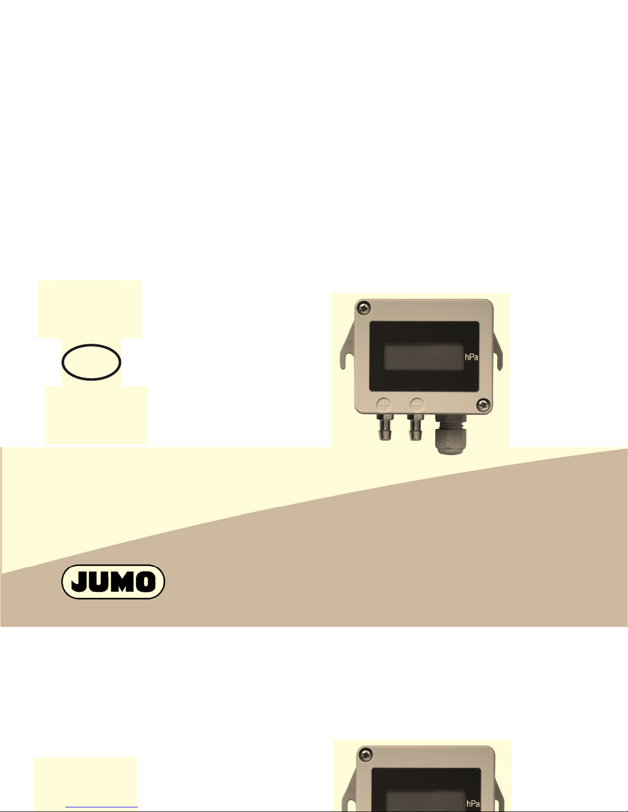
Multi-range
differential pressure transmitter
Type 40.2005
B40.2005
Operating instructions
2010/-10-11/00550566
Multi-range
differential pressure transmitter
Type 40.2005
DE
EN
FR
DE
Page 2
1 General
Do not blow into the pressure connections!
This will damage the instrument.
The instrument must only be operated within its
specifications!
It does not meet the requirements for “equipment
with a safety function”, as defined by Pressure
Equipment Directive 97/23/EC.
For hazardous media such as oxygen, acetylene,
combustible and toxic substances, refrigerating
plants, pressure vessels, etc., please comply with
existing, pertinent regulations!
Disregarding these regulations may result in
damage to property or personal injury.
1 General
Do not blow into the pressure connections!
This will damage the instrument.
The instrument must only be operated within its
specifications!
It does not meet the requirements for “equipment
Page 3
JUMO GmbH & Co. KG is certified according to DIN ISO
9001. The pressure transmitter described below complies
with DIN and VDE requirements. You have acquired a
product that in itself meets strict requirements and which
complies with or exceeds all the stated specifications.
However, should you have any cause for complaint, please
return the instrument to us, with an as accurate as possible
description of the discovered defect.
Please read these operating instructions before placing the
instrument in service.
We reserve the right to make technical changes to our
products.
Only suitably qualified personnel are allowed to
work on this instrument.
Should you need detailed technical information
about this instrument, please ask for data sheet
40.2005, or look on the Internet at: www.jumo.net
JUMO GmbH & Co. KG is certified according to DIN ISO
Only suitably qualified personnel are allowed to
work on this instrument.
Should you need detailed technical information
about this instrument, please ask for data sheet
40.2005, or look on the Internet at: www.jumo.net
Page 4

However, should you have any difficulties with starting up or
using our products, do not hesitate to contact us.
Phone: (06 61) 60 03-7 15
Fax: (06 61) 60 03-6 06
Internet: www.jumo.net
However, should you have any difficulties with starting up or
using our products, do not hesitate to contact us.
Phone: (06 61) 60 03-7 15
Fax: (06 61) 60 03-6 06
Internet: www.jumo.net
Page 5
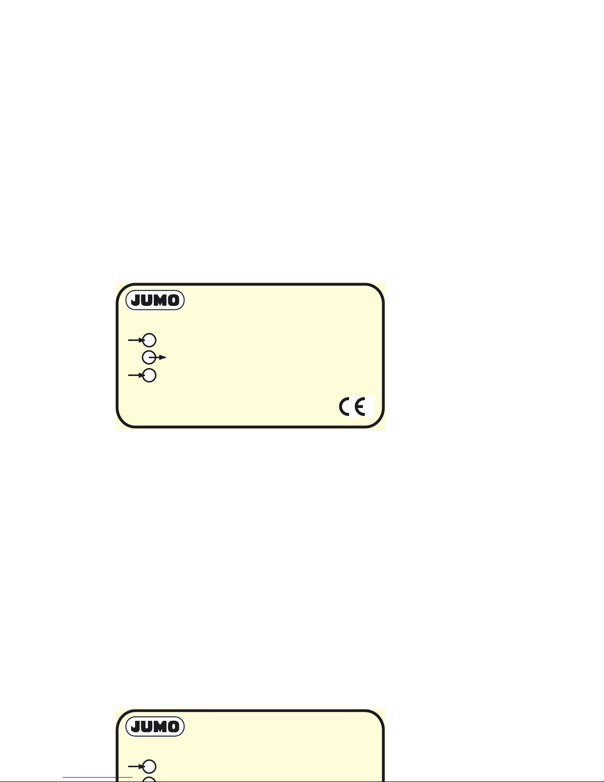
2 Instrument identification
The device version and the important data are located on
the nameplate.
(1) Pressure input
(2) Output signal
(3) Supply voltage
(4) Serial number
(5) Maximum pressure
TYP 402005
Made in Germany
: 0...2.5 / 5 / 7.5 / 10 hPa
: 0... 10 V / 0 (4)...20 mA
: 14...38 VDC / 12...31 VAC
: 00010610
: 680 hPa
0
Ser. Nr.
Pmax
(1)
(2)
(3)
(4)
(5)
2 Instrument identification
The device version and the important data are located on
the nameplate.
TYP 402005
Made in Germany
: 0...2.5 / 5 / 7.5 / 10 hPa
(1)
Page 6

3 Mounting
3.1 Operating conditions
Differential pressure can be measured in dry, non-ionizing
and aggressive gases with this measuring instrument.
It should not be installed near to sources of interference
(transformers, signal sources, electric motors) or sources of
heat.
Tremors or vibrations at the mounting location can lead to
measurement errors.
The instrument was adjusted at an ambient temperature of
20°C, vertically, with the process connection pointing down.
Any variation of this mounting position and ambient
temperature can cause measurement errors.
3 Mounting
3.1 Operating conditions
Differential pressure can be measured in dry, non-ionizing
and aggressive gases with this measuring instrument.
It should not be installed near to sources of interference
(transformers, signal sources, electric motors) or sources of
Page 7

3.2 Dimensions / attachment
86
67
76
14
49
29
R2.1
40
28
20
56
14
3.2 Dimensions / attachment
86
67
76
40
28
56
Page 8

4 Electrical connection
Only suitable qualified professionals are allowed to
connect the pressure transmitters!
Please comply with the regulations and safety
requirements for electrical, weak current and power
current installations, particularly taking into account
pertinent national regulations, such as VDE 0100.
The supply voltage must not be connected to
output signal terminals! This would result in an
instrument fault.
4 Electrical connection
Only suitable qualified professionals are allowed to
connect the pressure transmitters!
Please comply with the regulations and safety
requirements for electrical, weak current and power
current installations, particularly taking into account
Page 9

Connection Terminal
assignment
Screw
terminal
0(4) - 20 mA, 3 wires, output 409
Voltage supply
14 - 38 V DC,
12 - 31 V AC
U
B
0V/S-
S+
3
2/4
1
0 - 10 V DC, 3 wires, output 409
Voltage supply
14 - 38 V DC,
12 - 31 V AC
U
B
0V/S-
S+
3
2/4
1
42
3
1
Connection Terminal
assignment
Screw
terminal
0(4) - 20 mA, 3 wires, output 409
42
3
1
Page 10

5 Start-up
5.1 Pressure connection
✱ Connect the tube with the higher pressure to "+".
✱ Connect the tube with the lower pressure to "-".
5 Start-up
5.1 Pressure connection
✱ Connect the tube with the higher pressure to "+".
✱ Connect the tube with the lower pressure to "-".
Page 11

5.2 DIP switches
OFF
ON
T
4
2
3
5
6
7
8
9
1
Measuring range
Damping
Output signal
End value
Button
5.2 DIP switches
OFF
ON
T
8
9
Output signal
Button
Page 12

5.3 Setting the measuring range
5.4 Setting the output signal
Basic range
1
Basic range
2
S1 S2
Measuring
range
Measuring
range
25 hPa 2.5 hPa OFF OFF
50 hPa 5 hPa ON OFF
75 hPa 7.5 hPa OFF ON
100 hPa 10 hPa ON ON
Output
signal
S6 S7 S8 S9
0 - 10 V OFF OFF OFF ON
0-20mA OFF ON ON OFF
4 - 20 mA ON ON ON OFF
5.3 Setting the measuring range
Basic range
1
Basic range
2
S1 S2
Measuring
range
Measuring
range
25 hPa 2.5 hPa OFF OFF
50 hPa 5 hPa ON OFF
Page 13

5.5 Setting the damping
6 Calibration
6.1 Setting the zero point
✱ Disconnect both pressure tubes from the instrument.
✱ Open the instrument.
✱ DIP switch S5 is set to "OFF".
✱ Press the "T" key.
✱ Close the instrument.
✱ Re-connect the pressure tubes to the instrument.
Time constant S3 S4
10 ms OFF OFF
0.5 sec OFF ON
2 sec ON OFF
4sec ON ON
5.5 Setting the damping
Time constant S3 S4
10 ms OFF OFF
0.5 sec OFF ON
2 sec ON OFF
4sec ON ON
Page 14

6.2 Setting the end value for the output signal
✱ Open the instrument.
✱ Set DIP switch S5 to "ON".
✱ Apply the nominal pressure to the instrument.
✱ Press the "T" key.
✱ Set DIP switch S5 to "OFF".
✱ Close the instrument.
6.2 Setting the end value for the output signal
✱ Open the instrument.
✱ Set DIP switch S5 to "ON".
✱ Apply the nominal pressure to the instrument.
✱ Press the "T" key.
Page 15

Page 16

JUMO GmbH & Co. KG JUMO Instrument Co. Ltd. JUMO Process Control, Inc.
Street address:
Moritz-Juchheim-Straße 1
36039 Fulda, Germany
Delivery address:
Mackenrodtstraße 14
36039 Fulda, Germany
Postal address:
36035 Fulda, Germany
Phone: +49 661 6003-0
Fax: +49 661 6003-607
E-mail: mail@jumo.net
Internet: www.jumo.net
JUMO House
Temple Bank, Riverway
Harlow - Essex CM20 2DY, UK
Phone: +44 1279 63 55 33
Fax: +44 1279 63 52 62
E-mail: sales@jumo.co.uk
Internet: www.jumo.co.uk
8 Technology Boulevard
Canastota, NY 13032, USA
Phone: 315-697-JUMO
1-800-554-JUMO
Fax: 315-697-5867
E-mail: info@jumo.us
Internet: www.jumo.us
 Loading...