

Page 1

Handheld Meter for Conductivity (CR),
Specific Electrical Resistivity, TDS, and Salinity
Type 202710/30
Operating Manual
20271030T90Z001K000
V2.00/EN/00463204
Page 2

Page 3

Contents
1 Typographical conventions ...................................................... 5
1.1 Warning symbols .........................................................................................5
1.2 Note symbols ...............................................................................................5
2 General information .................................................................. 6
2.1 Preface .........................................................................................................6
2.2 Intended use ................................................................................................6
2.3 Safety information ........................................................................................6
2.4 Notes on operation and maintenance ..........................................................8
2.4.1 Battery operation .........................................................................................8
2.4.2 Power supply unit operation ........................................................................8
3 Identifying the device version .................................................. 9
3.1 Nameplate ....................................................................................................9
3.2 Order details .................................................................................................9
4 Operation ................................................................................. 10
4.1 Display .......................................................................................................10
4.2 Control elements ........................................................................................11
4.3 Connections ...............................................................................................12
4.4 Stand-up hinge ..........................................................................................12
5 Measuring ................................................................................ 13
5.1 The measuring cell .....................................................................................13
5.2 Switching on the device .............................................................................14
5.3 Measuring the conductivity ........................................................................14
5.4 Measuring the specific electrical resistivity ................................................15
5.5 Measuring the filtrate dry residue (TDS measurement) ..............................15
5.6 Measuring the salinity ................................................................................16
5.7 Temperature compensation .......................................................................17
5.7.1 Nonlinear temperature compensation "nLF" according to EN 27888 .......17
5.7.2 Linear temperature compensation "t.Lin" ..................................................18
5.8 Saving a measured value with the hold function (HLD) .............................18
6 Device settings ........................................................................ 19
6.1 Calling up the setting menu .......................................................................19
6.2 Resetting to default settings ......................................................................20
Page 4

Contents
6.3 Configuring the device ...............................................................................20
6.3.1 Submenu "SEt ConF": general settings .....................................................20
6.3.2 Submenu "SEt Out": serial interface settings ............................................28
6.4 Parameterizing the device ..........................................................................29
6.4.1 Submenu "SEt Corr": offset/zero point correction and slope correction
of the temperature measurement ..............................................................29
6.4.2 Submenu "SEt CLOC": setting the real-time clock ...................................30
6.4.3 Submenu "rEAd CAL.": reading the calibration data .................................32
7 Calibration ............................................................................... 33
7.1 Offset/zero point correction and slope correction of the
temperature input .......................................................................................33
7.2 Calibrating the relative time constant ........................................................33
7.2.1 Calibration using customer-specific reference solution
("CAL Edit" function) ..................................................................................33
7.2.2 Calibration using standard reference solutions ("CAL rEF.S" function) .....34
7.2.3 Error messages during calibration .............................................................35
7.3 Determining the relative time constant with a calculation .........................35
8 Maintenance ............................................................................ 36
8.1 Good laboratory practice (GLP) .................................................................36
8.1.1 Calibration timer ("C.Int") ...........................................................................36
8.1.2 Reading the calibration data ("rEAd CAL") ................................................36
8.2 Real-time clock ("CLOC") ..........................................................................37
9 Error and system messages .................................................. 38
10 Returns and disposal .............................................................. 39
10.1 Returns .......................................................................................................39
10.2 Disposal .....................................................................................................39
11 Technical data ......................................................................... 40
12 China RoHS ............................................................................. 42
Page 5

5
1 Typographical conventions
1.1 Warning symbols
1.2 Note symbols
DANGER!
This symbol indicates that personal injury from electrocution may occur if
the appropriate precautionary measures are not taken.
CAUTION!
This symbol in connection with the signal word indicates that damage to
assets or data loss will occur if the respective precautionary measures are
not taken.
NOTE!
This symbol refers to important information about the product, its handling,
or additional use.
✱ Action instruction
This symbol indicates that an action to be performed is described.
Page 6

6
2 General information
2.1 Preface
Read through this document carefully and familiarize yourself with the operation of the device before you start using it. Keep this document close at hand
and in the immediate vicinity of the device so that you or the specialist personnel can consult it at all times in case of doubt.
Mounting, startup, operation, maintenance, and decommissioning must only
be performed by personnel with a specialist qualification. The specialist personnel must have carefully read through and understood the operating manual
prior to commencing any work.
The liability and warranty of the manufacturer for damage and consequential
damage is rendered void in the event of improper use, failure to observe this
operating manual, deployment of personnel with insufficient qualifications,
and unauthorized modifications to the device.
The manufacturer is not liable for costs or damages incurred by the user or by
third parties through the use of this device, particularly in the event of
improper use of the device or in the event of misuse or malfunctions relating to
the connection or the device.
2.2 Intended use
When used with a securely connected sensor, the device is designed for measuring conductivity, specific electrical resistivity, salt content, and TDS.
The safety information (see chapter 2.3 "Safety information") in this operating
manual must be observed.
The device must only be used under the conditions or for the purposes for
which it has been designed.
The device must be handled with care, protected against pollutants, and used
according to the technical data.
2.3 Safety information
The device has been built and tested according to the safety regulations for
electrical measuring devices. Please observe the customary safety precautions and the device-specific safety information in this operating manual.
DANGER!
If it is assumed that risk-free operation of the device is no longer possible, the
device must be decommissioned and guarded against subsequent startup by
means of an identification marking. The safety of the user may be compromised by the device if, for example, the device
• features visible damage,
• no longer operates in the specified manner,
• has been stored in unsuitable conditions for an extended period of time.
In case of doubt, send the device to the manufacturer for repair/maintenance
.
Page 7

7
2 General information
DANGER!
Do not operate with a defective power supply unit!
In this case, potentially fatal excess voltage may occur at the sockets of the
device!
DANGER!
The device is not suitable for safety applications, emergency off equipment,
or applications in which a malfunction could lead to injuries and material
damage.
Failure to observe this note may lead to serious damage to health and material damage!
DANGER!
This device must not be used in a potentially explosive environment. If the
device is operated in a potentially explosive environment, there is an
increased hazard of deflagration, fire, or explosion due to formation of sparks!
NOTE!
The function and operational safety of the device can only be maintained
under the climatic conditions specified in chapter Chapter 11 "Technical
data", page 40.
If the device is transported from a cold environment to a warm environment,
the device may malfunction due to condensate formation. In this case, it is
necessary to wait for the device temperature to align with the room temperature prior to startup.
NOTE!
When connecting to other devices, take particular care in planning the wiring.
Under certain circumstances, internal connections in third-party devices (e.g.
connection of GND to ground) may lead to impermissible voltage potentials
that can cause impaired function or even destruction of the device itself or a
connected device.
NOTE!
Please do not connect any devices to socket 1 (see Chapter 4.3 "Con-
nections", page 12)!
Page 8

2 General information
8
2.4 Notes on operation and maintenance
2.4.1 Battery operation
2.4.2 Power supply unit operation
NOTE!
The device and sensor must be handled with care and used according to the
technical data (do not throw, do not subject to impact, etc.). The connectors
and sockets must be protected against pollutants.
NOTE!
If is displayed at the same time as "bAt" is shown in the bottom display,
the battery has been used up and must be replaced. However, the device
function remains guaranteed for a certain period of time.
If "bAt" is shown in the top display, the battery voltage is no longer sufficient
for device operation and the battery is now completely used up.
NOTE!
The battery must be removed if the device is stored at an ambient temperature of over 50 °C. The battery should be removed if the device is not used for
an extended period of time.
It is necessary to set the real-time clock once again after subsequent startup.
CAUTION!
When a power supply unit is connected, its voltage must be between
DC 10.5 V and 12 V. Do not generate any excess voltage! Basic power supply
units may feature excess open circuit voltage, which may lead to malfunction
or destruction of the device!
Prior to connecting the power supply unit to the electricity grid, it must be
ensured that the operating voltage stated on the power supply unit corresponds to the mains voltage.
Page 9

9
3 Identifying the device version
3.1 Nameplate
Position
The nameplate is affixed to the base of the battery compartment.
Example
Fabrication number (F-No.)
The fabrication number provides information such as the production date
(year/week). The production date relates to the characters in positions 12 to 15
(from the left).
Example: F-No. = 00822713 01 0 1815 0001
The device was produced in the 15th calendar week of 2018.
3.2 Order details
Handmessgerät 202710/30 – 000
F – Nr. 00822713 01 0 1815 0001
(1) Basic type
202710/30 Manual measuring device for conductivity (CR), specific
electrical resistivity, TDS, and salinity
(2) Extra codes
000 None
071 Including carry case
(1) (2)
Order code /
Order example 202710/30 / 000
Page 10

10
4 Operation
4.1 Display
(1) Display of the measured value unit
(2) Warning signal:
In case of low battery or recalibration request
(3) Temperature coefficient configuration unit
(4) Subsidiary display/subsidiary measured value:
Temperature measured value
(5) Display of the selected temperature compensation
(6) Display elements for the appearance of the minimum (MIN),
maximum (MAX), or saved measured value (HLD)
a
a
The "DIF" display is not supported in this device.
(7) Main display/main measured value:
Conductivity (mS/cm, µS/cm)
specific electrical resistivity (k
Ω
cm)
TDS/filtrate dry residue (mg/l)
Salinity (SAL)
6$/ PJO N2KP P6 6
/LQ/LQ Q/)Q/) $/ /RJJ . FP
0$; ',)
0,1 +/ '
)
Page 11

11
4 Operation
4.2 Control elements
The descriptions printed in black on the control keys relate to functions that
are available in measurement mode.
The descriptions and symbols printed in red on the control keys relate to functions that are available when setting the device.
Key Function
during the measurement
Function
in setting menu
On/off switch
min/max...
... pressed briefly:
Display minimum or maximum
value measured so far
... pressed for 2 seconds:
Delete the value in
question
/
Enter values or modify settings
CAL...
... pressed for 2 seconds:
Start calibration of the
relative cell constants
(only possible in operating
mode "cond" = conductivity)
"Scroll" through the parameter
sublevels of the submenu
Store:
Hold and save the
current measured value
("HLD" in display)
Quit:
Return to measuring, entries/
settings will be saved
Set...
... pressed briefly:
Toggle between units (only possible when setting the parameter "InP" to the value "SEt")
... pressed for 2 seconds:
Call up the setting menu
Menu:
Return to setting menu, entries/
settings will be saved
ON
OFF
1
5
min
max
2
CAL
3
6
Store
Quit
4
Set
Menu
Page 12

4 Operation
12
4.3 Connections
4.4 Stand-up hinge
Operation: ✱ Pull on the "open" lettering to fold out the stand-up hinge to a position of
90 ° (1). Pull on the "open" lettering again to fold out the stand-up hinge to
a position of 180 ° (2).
Functions: When the stand-up hinge is closed, the device can be laid flat on the table or
secured on a belt.
When the stand-up hinge is at a position of 90 °, the device can be set up on
an even surface.
When the stand-up hinge is at a position of 180 °, the device can be hung on
a hook, for example.
(1)
This socket does not have a function, please do not connect any devices
(2) Connecting cable of the securely connected conductivity measuring cell
(3) Socket for connecting a power supply unit
Stand-up hinge closed
Stand-up hinge positioned at 90°/180°
Page 13

13
5 Measuring
5.1 The measuring cell
The conductivity measurement is a relatively straightforward measurement.
The measuring cell that is securely connected to the device remains stable for
a long time when properly used and can be aligned using the integrated calibration function (see chapter 7.2, page 33).
Use
For measuring purposes, the measuring cell must be immersed in the measurement medium to a minimum depth of 30 mm and a maximum depth of
110 mm.
The measuring cell can be stored dry or standing in clean water.
A measuring cell that has been stored under dry conditions requires a slightly
longer time to display a stable measured value than a measuring cell that has
been stored under wet conditions.
Before the measuring cell is moved into a liquid with a significantly different
conductivity, it should be rinsed and the residual moisture should be captured
with an absorbent cloth or paper.
If an unexpectedly high or low conductivity is measured, this can be traced
back to pollutants on the electrodes. In this case, the measuring cell can be
cleaned with an aqueous detergent solution.
NOTE!
Never bring the measuring cell into contact with water-repellent substances
such as oil or silicone.
When performing measurements in measurement media with low conductivity,
it is necessary to ensure sufficient flow to the electrodes.
Page 14
5 Measuring
14
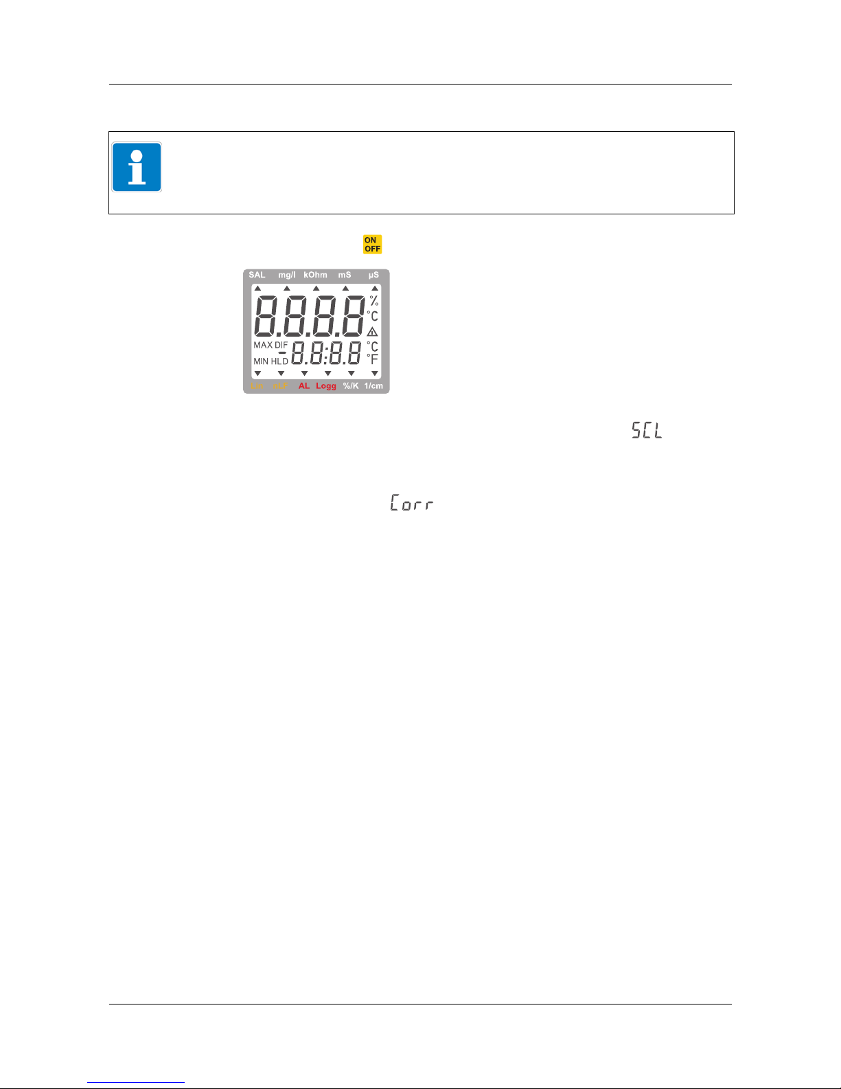
5.2 Switching on the device
✱ Briefly press the key.
If a correction of the relative cell constant (see chapter 7.2, page 33) has been
performed, the device accordingly provides a brief display of " " and the
set relative cell constant after the segment test.
If a zero point correction (offset) or slope correction has been performed on
the temperature sensor (see chapter 7.1, page 33), the device accordingly provides a brief display of " " after the segment test.
The device is subsequently ready to commence measuring.
5.3 Measuring the conductivity
Definition
Conductivity
1
is the ability of a material or an electrolyte to conduct electric
current.
In aqueous solutions (electrolytes), the current flows through the charge trans-
port of the ions dissolved in the electrolyte. The conductivity measurement is
therefore excellently suited to determining the concentration of saline solutions, acids, and lyes.
The conductivity is the reciprocal of the specific electrical resistivity and is
stated by the device in µS/cm or mS/cm.
Select the measurand
The device is preconfigured per default for measuring the conductivity
with automatic selection of the measuring range (Auto Range).
If the device has been configured for a different measurand in a userdefined operation, first change the measurand (see "Parameter "InP":
selection of a measurand", page 21).
If the measuring range is selected automatically, the measuring range with the
best dissolution is always selected from the measuring ranges listed.
NOTE!
The device is preconfigured per default for measuring the conductivity
with automatic selection of the measuring range (Auto Range).
The device activates all display segments
for a short time (segment test).
1
Specifically relates to electrical conductivity here
Page 15

15
5 Measuring
Measuring ranges
• 0.0 to 200.0 µS/cm
• 0 to 2000 µS/cm
• 0.00to20.0mS/cm
• 0.0 to 200.0 mS/cm
For the purpose of measurement, a fixed set measuring range can also be
selected instead of the measuring range being selected automatically, see
"Parameter "rAnG": selection of the display range or the measuring range",
page 23.
5.4 Measuring the specific electrical resistivity
Definition
The specific electrical resistivity is the reciprocal of the conductivity and is
stated by the device in kOhm × cm.
Select the measurand
If the device has been configured for a different measurand in a userdefined operation, first change the measurand (see "Parameter "InP":
selection of a measurand", page 21).
If the measuring range is selected automatically, the measuring range with the
best dissolution is always selected from the measuring ranges listed.
Measuring ranges
• 0.000 to 2.000 k
Ω ×cm
• 0.00 to 20.00 k
Ω ×cm
• 0.0 to 100.0 k
Ω ×cm
For the purpose of measurement, a fixed set measuring range can also be
selected instead of the measuring range being selected automatically, see
"Parameter "rAnG": selection of the display range or the measuring range",
page 23.
5.5 Measuring the filtrate dry residue (TDS measurement)
Definition
The TDS measurement (Total Dissolved Solids) uses the conductivity and a
conversion factor "C.tdS" to determine the filtrate dry residue TDS (evaporation residue). The conversion factor is entered manually in the configuration
menu of the device (see "Parameter "C.tdS": conversion factor for TDS measurement", page 22).
This method is well suited to performing simple concentration measurements,
e.g. of salt solutions. The results are displayed in mg/l.
Display value TDS (in mg/l) = conductivity (in µS/cm) × C.tdS (conversion
factor) at temperature compensation (t.Cor) = "nLF" and
reference temperature (t.rEF) = 25 °C.
Page 16

5 Measuring
16
The following approximate values apply for C.tdS:
Select the measurand
If the device has been configured for a different measurand in a userdefined operation, first change the measurand (see "Parameter "InP":
selection of a measurand", page 21).
If the measuring range is selected automatically (default setting), the measuring range with the best dissolution is always selected from the measuring
ranges listed below.
Measuring ranges
• 0.0 to 200.0 mg/l
• 0 to 2000 mg/l
For the purpose of measurement, a fixed set measuring range can also be
selected instead of the measuring range being selected automatically, see
"Parameter "rAnG": selection of the display range or the measuring range",
page 23.
5.6 Measuring the salinity
Definition
The salinity (salt content) of seawater can be measured in the measurement
type "SAL".
The display in the device does not feature a unit and corresponds to the salt
content in g/kg (grams of salt per kilogram of seawater) or per mil (‰). The
description "PSU" (Practical Salinity Unit) is also commonly used.
The salinity measurement in this device relates to the International Oceanographic Tables (IOT). Accordingly, a salinity of 35 g/kg is taken as a reference
value (standard mass concentration) for seawater.
However, depending on the location, weather, seasons, etc., the salt composition at the various measurement points may deviate from the standard mass
concentration, sometimes considerably. Refer to the IOT tables in such cases.
0.50 Monovalent salts with 2 ion types (NaCl, KCl, etc.)
0.50 Natural waters/surface water, drinking water
0.65 to 0.70 Salt concentration of aqueous fertilizer solutions
NOTE!
The stated values for "C.tdS" are only reference values that are good for estimates but are not suitable for precise measurements.
For precise measurements, the conversion factor must be determined for the
respective solution type and the concentration range being considered.
This can be performed either through calibration with familiar comparative
solutions or through actual evaporation of a certain quantity of fluid with a
determined conductivity and subsequent weighing of the dry residue.
Page 17

17
5 Measuring
Select the measurand
If the device has been configured for a different measurand in a userdefined operation, first change the measurand (see "Parameter "InP":
selection of a measurand", page 21).
Measuring range
• 0.0 to 70.0 ‰ (g/kg)
5.7 Temperature compensation
The conductivity and TDS of aqueous solutions depend on the temperature.
Thanks to the temperature compensation, the solution is counted back to a
uniform reference temperature.
The normal reference temperature, which is preset in the device, is 25 °C.
5.7.1 Nonlinear temperature compensation "nLF" according to EN
27888
The nonlinear temperature compensation for natural waters ("nLF" according
to EN 27888) is sufficiently accurate for most applications, for example in the
area of fish breeding and for measuring surface water and drinking water.
Recommended area of application
The "nLF" compensation is recommended for conductivity measurements
between 60 µS/cm and 1000 µS/cm.
NOTE!
This measurement is intended exclusively for measuring seawater. The salinity measurement is not suitable for determining the salt concentration of other
saline solutions. A measurement according to TDS is recommended in such
cases, see Page 15.
NOTE!
The salinity measurement features dedicated automatic temperature compensation, independent of the menu settings concerning temperature compensation for conductivity.
Page 18

5 Measuring
18
5.7.2 Linear temperature compensation "t.Lin"
If the temperature compensation type is not precisely known, the "linear temperature compensation" is used in practice (see "Parameter "t.Lin": compensation coefficient", page 25). This involves making the simplified assumption
that the ratio of the temperature to the concentration will take a linear trajectory across the measuring range being considered.
Conductivity calculation within the device
The conductivity is hereby calculated using the following equation. In this
regard, the parameter "t.Lin" corresponds to the formula value "TK
lin
".
Calculating the temperature coefficient
A temperature coefficient can be calculated, for example, by determining the
conductivity of a solution at 2 temperatures (T1 and T2) with the temperature
compensation switched off (t.Cor = oFF).
5.8 Saving a measured value with the hold function (HLD)
The device features a "HOLD" function for saving a measured value.
Depending on the device configuration (see "Parameter "Auto HLD": auto-
matic saving of a measured value", page 27), the measured value can be
saved either by pressing the key or automatically when a stable measured
value is reached.
When the measured value has been saved successfully, the message "HLD"
appears on the device display.
Press the key again to delete the saved value.
When automatic saving is activated, the next stable measured value will subsequently be saved.
LF
Tre f
= Conductivity at reference temperature
TK
lin
= Linear temperature coefficient
LF
Tx
= Uncompensated conductivity at
current temperature
Tx = Current temperature
Tref = Reference temperature
TK
lin
= Linear temperature coefficient
LF
T1
= Conductivity at temperature T1
LF
T2
= Conductivity at temperature T2
NOTE!
Temperature coefficients of around 2.0 %/K are most common.
Page 19

19
6 Device settings
6.1 Calling up the setting menu
Overview of the setting menu
The setting menu is called up from measurement mode by pressing the
key for at least 2 seconds (main display "SEt").
The 5 individual submenus in the setting menu are then selected by repeatedly
pressing the key.
Measuring (1) Display in measurement mode
Configuring
the device
(2) General settings, see page 20
(3) Settings for the serial output, see page 28
Parameterizing
the device
(4) Offset/zero point correction and slope correction of the temperature measurement, see page 29
(5) Settings for the real-time clock, see page 30
Providing information
(6) Read calibration data
a
, see page 36
a
Only possible if calibration data is stored in the device.
SAL mg/l kOhm mS µS
Lin nLF AL Logg %/K 1/cm
SAL mg/l kOhm mS µS
Lin nLF AL Logg %/K 1/cm
SAL mg/l kOhm mS µS
Lin nLF AL Logg %/K 1/cm
SAL mg/l kOhm mS µS
Lin nLF AL Logg %/K 1/cm
SAL mg/l kOhm mS µS
Lin nLF AL Logg %/K 1/cm
4
Set
Menu
6
Store
Quit
SAL mg/l kOhm mS µS
Lin nLF AL Logg %/K 1/cm
> 2 s> 2 s
4
Set
Menu
4
Set
Menu
4
Set
Menu
4
Set
Menu
4
Set
Menu
6
Store
Quit
6
Store
Quit
6
Store
Quit
6
Store
Quit
(2)
(3)
(4)(5)
(6)
(1)
NOTE!
The configuration is stopped if no keys are pressed for over 2 minutes. Any
changes made up to this point will not be saved!
Page 20

6 Device settings
20
6.2 Resetting to default settings
6.3 Configuring the device
6.3.1 Submenu "SEt ConF": general settings
Overview of the parameters
After calling up the setting menu with and selecting the submenu "SEt
ConF", use the key to select the parameter to be configured.
NOTE!
If the and keys are pressed simultaneously for over 2 seconds, the
device is reset to the default settings.
SAL mg/l kOhm mS µS
Lin nLF AL Logg %/K 1/cm
CAL
3
HLD
(1)
(2)
(3)
(4)
(5)
(6)
(7) (8)
(9)
(10)
(11)
(12)
(13)
NOTE!
Certain parameters can only be accessed when certain device settings have
been made.
Page 21

21
6 Device settings
Parameter "InP": selection of a measurand
✱ Select the desired measurand with the and keys:
✱ Press the key to save the setting and move to the next parameter or
✱ press the key to save the setting and move to the next submenu of the
setting menu or
✱ press the key to save the setting, quit the device settings, and return to
measurement mode.
Parameters
(1) "InP": selection of a measurand, see page 21
(2) "C.tdS": conversion factor for TDS measurement, see page 22
(3) "CELL Corr": setting the relative cell constant, see page 22
(4) "rAnG": selection of the display range or the measuring range, see page 23
(5) "CAL": preconfiguration for the calibration of the relative cell constant,
see page 23
(6) "rEF.S": selection of the standard reference solution for the calibration of the
relative cell constant, see page 24
(7) "Unit t": temperature unit °C/°F, see page 24
(8) "t.Cor": setting the temperature compensation, see page 25
(9) "t.Lin": compensation coefficient, see page 25
(10) "t.rEF": setting the reference temperature, see page 26
(11) "C.int": calibration timer, see page 26
(12) "Auto HLD": automatic saving of a measured value, see page 27
(13) "P.oFF": automatic device switch-off, see page 27
NOTE!
In the following list of parameters, the setting options for the default setting
are shown in bold in each case.
Menu/parameter Setting option Meaning
Cond Conductivity
rESi Specific electrical resistivity
tdS Filtrate dry residue
SAL Salinity (salt content)
SEt Selection of the measurand in measure-
ment mode using the "Set" key
Page 22

6 Device settings
22
Parameter "C.tdS": conversion factor for TDS measurement
The parameter "C.tdS" can only be accessed when the measurand "TDS" is
selected.
✱ Use the and keys to set the conversion factor:
✱ Press the key to save the setting and move to the next parameter or
✱ press the key to save the setting and move to the next submenu of the
setting menu or
✱ press the key to save the setting, quit the device settings, and return to
measurement mode.
Parameter "CELL Corr": setting the relative cell constant
✱ Use the and keys to manually set the relative cell constant:
✱ Press the key to save the setting and move to the next parameter or
✱ press the key to save the setting and move to the next submenu of the
setting menu or
✱ press the key to save the setting, quit the device settings, and return to
measurement mode.
Menu/parameter Setting option Meaning
0.40 to 1.00 Conversion factor for TDS measurement
Menu/parameter Setting option Meaning
0.800 to
1.000 to
1.200
Manual setting of the relative
cell constant
Page 23

23
6 Device settings
Parameter "rAnG": selection of the display range or the measuring range
The parameter "rAnG" can only be accessed when one of the measurands
"Conductivity", "Specific electrical resistivity", or "TDS" is selected.
✱ Use the and keys to select the display range:
✱ Press the key to save the setting and move to the next parameter or
✱ press the key to save the setting and move to the next submenu of the
setting menu or
✱ press the key to save the setting, quit the device settings, and return to
measurement mode.
Parameter "CAL": preconfiguration for the calibration of the relative cell constant
The parameter "CAL" can only be accessed when the measurand
"Conductivity" is selected.
✱ Use the and keys to choose whether alignment should be per-
formed with a customer-specific reference solution (Edit) or with a selection
of standard reference solutions (rEF.S):
✱ Press the key to save the setting and move to the next parameter or
✱ press the key to save the setting and move to the next submenu of the
setting menu or
✱ press the key to save the setting, quit the device settings, and return to
measurement mode.
Menu/parameter Setting option Meaning
Auto Automatic measuring
range selection
Measurand
200.0 µS/cm 0.0 to 200.0 µS/cm Conductivity
2000 µS/cm 0 to 2000 µS/cm
20.0 mS/cm 0.00 to 20.0 mS/cm
200.0 mS/cm 0.0 to 200.0 mS/cm
2.000 kohm 0.00 to 2.000 kΩ × cm Specific electri-
cal resistivity
20.00 kohm 0.00 to 20.00 kΩ × cm
100.0 kohm 0.0 to 100.0 kΩ × cm
200.0 mg/l 0.0 to 200.0 mg/l TDS
2000 mg/l 0 to 2000 mg/l
Menu/parameter Setting option Meaning
Edit Customer-specific reference solution
rEF.S Standard reference solutions
Page 24

6 Device settings
24
Parameter "rEF.S": selection of the standard reference solution for the calibration of the relative cell constant
If a selection has been made to calibrate the relative cell constant with a selection of standard reference solutions (see page 23), use this parameter to specify a standard reference solution for calibrating the relative cell constant.
✱ Use the and keys to select one of the standard reference solutions:
✱ Press the key to save the setting and move to the next parameter or
✱ press the key to save the setting and move to the next submenu of the
setting menu or
✱ press the key to save the setting, quit the device settings, and return to
measurement mode.
Parameter "Unit t": temperature unit °C/°F
✱ Use the and keys to select the temperature unit:
✱ Press the key to save the setting and move to the next parameter or
✱ press the key to save the setting and move to the next submenu of the
setting menu or
✱ press the key to save the setting, quit the device settings, and return to
measurement mode.
Menu/parameter Setting option Meaning
1413 µS Reference solution 0.01 M KCl
2760 µS Reference solution 0.02 M KCl
12.88 mS/cm Reference solution 0.1 M KCl
50 mS/cm Seawater comparative solution KCl
111.8 mS/cm Reference solution 1 M KCl
Menu/parameter Setting option Meaning
°C All temperatures stated in degrees
Celsius
°F All temperatures stated in degrees
Fahrenheit
Page 25

25
6 Device settings
Parameter "t.Cor": setting the temperature compensation
The parameter "t.Cor" cannot be selected when the measurand "Salinity" is
selected.
✱ Use the and keys to select the temperature compensation:
✱ Press the key to save the setting and move to the next parameter or
✱ press the key to save the setting and move to the next submenu of the
setting menu or
✱ press the key to save the setting, quit the device settings, and return to
measurement mode.
Parameter "t.Lin": compensation coefficient
The parameter "t.Lin" can only be selected if the setting option "Lin" has been
chosen when selecting the temperature compensation ("t.Cor").
To determine the compensation coefficient see chapter 5.7.2 "Linear temperature compensation "t.Lin"", page 18.
✱ Use the and keys to set the temperature coefficient:
✱ Press the key to save the setting and move to the next parameter or
✱ press the key to save the setting and move to the next submenu of the
setting menu or
✱ press the key to save the setting, quit the device settings, and return to
measurement mode.
Menu/parameter Setting option Meaning
oFF Do not compensate conductivity measure-
ment
nLF Nonlinear function for natural waters
according to EN 27888 (ISO 7888), e.g.
for groundwater, surface water, or drinking water
Lin Linear temperature compensation
Menu/parameter Setting option Meaning
0.300 to
2.000 to
3.000
Temperature coefficient in %/K
Page 26

6 Device settings
26
Parameter "t.rEF": setting the reference temperature
The parameter "t.rEF" can only be accessed if the setting option "Lin" or "nLF"
has been chosen when selecting the temperature compensation (t.Cor).
✱ Use the and keys to set the reference temperature:
✱ Press the key to save the setting and move to the next parameter or
✱ press the key to save the setting and move to the next submenu of the
setting menu or
✱ press the key to save the setting, quit the device settings, and return to
measurement mode.
Parameter "C.int": calibration timer
✱ Use the and keys to set the calibration timer:
✱ Press the key to save the setting and move to the next parameter or
✱ press the key to save the setting and move to the next submenu of the
setting menu or
✱ press the key to save the setting, quit the device settings, and return to
measurement mode.
Menu/parameter Setting option Meaning
25°C/77°F Reference temperature 25°C/77°F
20°C/68°F Reference temperature 20°C/68°F
Menu/parameter Setting option Meaning
1 to 730 Time interval for calibration timer in days
oFF No calibration timer
Page 27

27
6 Device settings
Parameter "Auto HLD": automatic saving of a measured value
✱ Use the and keys to activate or deactivate automatic saving of a
measured value:
✱ Press the key to save the setting and move to the next parameter or
✱ press the key to save the setting and move to the next submenu of the
setting menu or
✱ press the key to save the setting, quit the device settings, and return to
measurement mode.
Parameter "P.oFF": automatic device switch-off
✱ Use the and keys to set the switch-off delay:
✱ Press the key to save the setting and move to the next parameter or
✱ press the key to save the setting and move to the next submenu of the
setting menu or
✱ press the key to save the setting, quit the device settings, and return to
measurement mode.
Menu/parameter Setting option Meaning
on Automatic saving of a stable measured
value (Auto Hold)
oFF Standard hold function at the push of a
button (see chapter 4.2 "Control elements", page 11)
Menu/parameter Setting option Meaning
1to
20 to
120
Switch-off delay in minutes.
If no key is pressed, the device switches off
automatically once this period of time has
elapsed
oFF Automatic switch-off deactivated
(permanent operation)
Page 28

6 Device settings
28
6.3.2 Submenu "SEt Out": serial interface settings
Overview of the parameters
After calling up the setting menu with and selecting the submenu "SEt
Out", use the key to select the parameter to be configured.
Parameter "Out": serial interface
✱ Use the and keys to deactivate the interface:
✱ Press the key to save the setting and move to the next submenu of the
setting menu or
✱ press the key to save the setting, quit the device settings, and return to
measurement mode.
CAL
3
SAL mg/l kOhm mS µS
Lin nLF AL Logg %/K 1/cm
NOTE!
The functions of the serial interface are not supported in this device. The
interface should always be deactivated in order to minimize power consumption.
Menu/parameter Setting option Meaning
oFF Interface deactivated.
Minimizes the power consumption of the
device
Ser Interface activated.
Not supported in this device; increases
the power consumption of the device!
Page 29

29
6 Device settings
6.4 Parameterizing the device
6.4.1 Submenu "SEt Corr": offset/zero point correction and slope correction of the temperature measurement
Overview of the parameters
After calling up the setting menu with and selecting the submenu
"SEt Corr", use to select the parameter to be configured.
Parameter "OFFS": offset/zero point correction of the temperature measurement
✱ Use the and keys to set the zero point correction:
✱ Press the key to save the setting and move to the next parameter or
✱ press the key to save the setting and move to the next submenu of the
setting menu or
✱ press the key to save the setting, quit the device settings, and return to
measurement mode.
Parameters
(1) "OFFS": offset/zero point correction of the temperature measurement, see
page 29
(2) "SCAL": slope correction of the temperature measurement, see page 30
CAL
3
(1)
(2)
SAL mg/l kOhm mS µS
Lin nLF AL Logg %/K 1/cm
Menu/parameter Setting option Meaning
oFF No zero point correction of the
temperature measurement
-5.0 to +5.0°C Zero point correction of the
temperature measurement in °C
-9.0 to +9.0°F Zero point correction of the
temperature measurement in °F
Page 30

6 Device settings
30
Parameter "SCAL": slope correction of the temperature measurement
✱ Use the and keys to set the slope correction:
✱ Press the key to save the setting and move to the next parameter or
✱ press the key to save the setting and move to the next submenu of the
setting menu or
✱ press the key to save the setting, quit the device settings, and return to
measurement mode.
6.4.2 Submenu "SEt CLOC": setting the real-time clock
Overview of the parameters
After calling up the setting menu with and selecting the submenu
"SEt CLOC", use to select the parameter to be configured.
Menu/parameter Setting option Meaning
oFF No slope correction of the
temperature measurement
-5.0 to 5.0 Slope correction of the
temperature measurement in %
Parameters
(1) "CLOC": setting the time, see page 31
(2) "YEAr": setting the year, see page 31
(3) "dAtE": setting the date, see page 32
CAL
3
(1)
(2)
SAL mg/l kOhm mS µS
Lin nLF AL Logg %/K 1/cm
(3)
Page 31

31
6 Device settings
Parameter "CLOC": setting the time
✱ Use the and keys to set the time:
✱ Press the key to save the setting and move to the next parameter or
✱ press the key to save the setting and move to the next submenu of the
setting menu or
✱ press the key to save the setting, quit the device settings, and return to
measurement mode.
Parameter "YEAr": setting the year
✱ Use the and keys to set the year:
✱ Press the key to save the setting and move to the next parameter or
✱ press the key to save the setting and move to the next submenu of the
setting menu or
✱ press the key to save the setting, quit the device settings, and return to
measurement mode.
Menu/parameter Setting option Meaning
HH:MM Hours (HH) and minutes (MM)
Press the
/ keys to set the time in incre-
ments of 1 minute
Press and hold the / keys to continu-
ously move through the time setting; press
and hold for an extended period to move in
increments of 10 minutes
Menu/parameter Setting option Meaning
YYYY 4-digit year
Page 32

6 Device settings
32
Parameter "dAtE": setting the date
✱ Use the and keys to set the date:
✱ Press the key to save the setting and move to the next parameter or
✱ press the key to save the setting and move to the next submenu of the
setting menu or
✱ press the key to save the setting, quit the device settings, and return to
measurement mode.
6.4.3 Submenu "rEAd CAL.": reading the calibration data
The reading of the calibration data is described separately, see chapter 8.1.2
"Reading the calibration data ("rEAd CAL")", page 36.
Menu/parameter Setting option Meaning
DD:MM Days (DD) and months (MM)
Page 33

33
7 Calibration
7.1 Offset/zero point correction and slope correction of the
temperature input
The parameters "OFFS" (see page 29) and "SCAL" (see page 30) can be used
to carry out a zero point correction or slope correction of the temperature
input.
Reliable references (e.g. ice water, controlled precision water baths, or similar)
must be available for this purpose.
If a correction has been carried out (deviation from the default setting), this is
indicated with the message "Corr" when the device is switched on.
The default setting of the zero point and slope values is: "oFF" = 0.0, i.e. no
correction performed.
Effect of the correction on the temperature display
7.2 Calibrating the relative time constant
In addition to direct entry, the relative cell constant can also be determined
automatically via the parameter "CELL Corr" (see page 22).
7.2.1 Calibration using customer-specific reference solution ("CAL Edit" function)
This function enables the user to automatically calibrate the relative cell constant with a user-specific reference solution featuring a precisely identified
conductivity.
Menu selection
✱ Start configuration.
✱ Select submenu "SEt ConF".
✱ Call up parameter "CAL".
✱ Use the and keys to select the "Edit" setting option.
Measuring
✱ Immerse the conductivity measuring cell in the reference solution.
✱ Press the key for >2 s.
Correction type Device display
Offset/zero point correction Measured value – "OFFS"
Offset/zero point correction and
slope correction
(measured value – "OFFS") × (1+ "SCAL"/100)
The main display of the device shows the measured
actual value (e.g. 1796 µS/cm) and the subsidiary display shows "CAL." with a symbol rotating around the
last digit.
Page 34

7 Calibration
34
Calibration
✱ Use the and keys to enter the value of the reference solution.
✱ Press the key to save the setting.
The device will then return to measurement mode, or it will display an error
message if necessary.
The resulting relative cell constant is briefly shown and can always be viewed
in the "SEt ConF" menu under the parameter "CELL Corr".
7.2.2 Calibration using standard reference solutions ("CAL rEF.S" function)
This function enables the user to automatically calibrate the relative cell constant with a selection of standard reference solutions.
Menu selection
✱ Start configuration.
✱ Select submenu "SEt ConF".
✱ Call up parameter "CAL".
✱ Use the and keys to select the "REF.S" setting option.
Selecting the standard reference solution
✱ Press the key to call up the parameter "rEF.S".
✱ Use the and keys to select one of the standard reference solutions:
✱ Press the key to save the setting.
The device will then return to measurement mode.
Calibration
✱ Immerse the conductivity measuring cell in the standard reference solution.
✱ Press the key for >2 s.
Menu/parameter
Setting option
a
a
The specifications relate to 25 °C. The temperature responses of the standard reference solutions are stored in the device and are automatically compensated.
Meaning
1413 µS Reference solution 0.01 M KCl
2760 µS Reference solution 0.02 M KCl
12.88 mS/cm Reference solution 0.1 M KCl
50 mS/cm Seawater comparative solution KCl
111.8 mS/cm Reference solution 1 M KCl
Page 35

35
7 Calibration
Once a stable value has been determined, the device will save the correction
factor and return to measurement mode, or it will display an error message if
necessary.
The resulting relative cell constant is briefly shown and can always be viewed
in the "SEt ConF" menu under the parameter "CELL Corr".
7.2.3 Error messages during calibration
7.3 Determining the relative time constant with a calculation
As an alternative to calibrating the relative time constant, this can also be
determined using a calculation and manually entered on the device using the
parameter "CELL Corr". A reference solution is also required for this purpose.
The calculation is carried out as stated in the following example.
Example
KCl solution with the concentration 0.1 M: 1413 µS/cm at 25°C
(At other temperatures, switch off the temperature compensation (t.Cor = oFF)
and use the conductivity value that corresponds to the temperature!)
Assumption:
Conductivity
display
= 1500 µS × cm-1 at set relative cell constant
("CELL Corr") out of 1.000
Conductivity of the solution at 25 °C (conductivity
target
) = 1413 µS × cm
-1
In this example, the parameter "CELL Corr" must be set to the value "0.942".
The main display of the device shows the measured actual
value (e.g. 1407 µS/cm) and the subsidiary display shows
"CAL." with a symbol rotating around the last digit.
Display Meaning Explanation
CAL.-Err.1 Relative cell constant too large Determined relative cell constant
must not be > 1.2
CAL.-Err.2 Relative cell constant too small Determined relative cell constant
must not be < 0.8
CAL.-Err.3 Solution in incorrect range Incorrect reference solution, way
beyond the tolerance
CAL.-Err.4 Incorrect temperature Reference solution outside the per-
missible temperature (0.0 to 34.0 °C,
or 0.0 to 27.0 °C with reference solution 111.8 mS/cm)
Relative cell constant k =
Page 36

36
8 Maintenance
8.1 Good laboratory practice (GLP)
Good laboratory practice involves regularly monitoring the device and the
accessories. In the case of conductivity measurements, the correct calibration
of the relative cell constants must be ensured in particular. The device provides support in this regard with the functions "C.int" (calibration timer) and
"rEAD CAL" (calibration data display).
8.1.1 Calibration timer ("C.Int")
You can enter a fixed interval upon which the device will automatically remind
you that a new calibration needs to be performed.
The length of the interval depends on your application.
Once the interval has elapsed, "CAL" flashes in the display.
To set the interval see "Parameter "C.int": calibration timer", page 26
8.1.2 Reading the calibration data ("rEAd CAL")
The last calibration is stored in the device with the date and calibration values
and can be called up as follows.
✱ Press the key for at least 2 seconds.
"Set ConF" appears in the display.
✱ Keep pressing the key until "rEAd CAL." appears in the display.
✱ Briefly press the key to switch the display between:
✱ Press the key to stop reading the calibration data.
"Cal." and "FACt" are displayed alternately
in the main display
The value of the relative cell constant is shown in the subsidiary display
"Cal." and "rEF" are displayed alternately
in the main display
The reference value with which the relative cell constant was
aligned is shown in the subsidiary display
The date of the data record is shown
in the main display
The time of the data record is shown in the
subsidiary display
Page 37

37
8 Maintenance
8.2 Real-time clock ("CLOC")
The real-time clock is used for the chronological assignment of the calibration.
You should therefore check the settings as required, particularly after replacing
the battery.
Page 38

38
9 Error and system messages
Error messages during measurement
Error message during automatic alignment
Display Cause Remedy
Battery voltage low,
the function can still be guaranteed
only for a short time.
Insert new battery
Battery is used up Insert new battery
During mains operation: incorrect voltage
Test power supply unit, replace if necessary
No display
or muddled characters, device
does not respond
to keys being
pressed
Battery voltage too low Insert new battery
During mains operation: power supply
unit defective or incorrect voltage/polarity
Test power supply unit, replace if necessary
System error Remove battery or power supply unit, wait briefly
before reconnecting
Device error/device defect Send in device for repair
Measuring range exceeded Check whether the measured value is above the
permissible measuring range of the sensor
Measuring cell is defective Send in device for repair
Measuring range not reached Check whether the measured value is below the
permissible measuring range of the sensor
Measuring cell is defective Send in device for repair
System error Send in device for repair
Measuring range exceeded or not
reached by a significant margin
Check whether the measured value is within the
permissible measuring range of the sensor
Display value cannot be calculated,
measuring range or input value
exceeded
Check measuring range
Display value cannot be calculated,
measured values too unstable
Wait for signal control of the device
Preset calibration interval elapsed
Calibrate device
Last calibration invalid
Display Cause Remedy
Relative cell constant too large
Determined relative cell constant
must not be > 1.2
Relative cell constant too small
Determined relative cell constant
must not be < 0.8
Solution in incorrect range
Incorrect reference solution, way beyond
the tolerance
Incorrect temperature
Reference solution outside the permissible tem-
perature (0.0 to 34.0°C, or 0.0 to 27.0°C with
reference solution 111.8 mS/cm)
Page 39

39
10 Returns and disposal
10.1 Returns
10.2 Disposal
DANGER!
All devices that are returned to the manufacturer must be free from measuring
material residue and other hazardous substances. Measuring material residue
on the case or on the sensor may pose a hazard to persons or the environment.
NOTE!
Use suitable transport packaging when returning the device, especially if the
device is still functioning.
Ensure that the device is protected by sufficient insulation material in the
packaging.
DISPOSAL!
Hand in empty batteries at the corresponding collection points.
Do not dispose of the device in the household waste. Should the device need
to be disposed of, please send this directly to us (with the sufficient postage).
We will dispose of the device in a proper and environmentally friendly manner.
Page 40

40
11 Technical data
Measuring ranges
Accuracy
Connections
Measuring cell
Display
Additional functions
Case
Power supply
Conductivity 0.0 to 200.0 µS/cm
0to2000µS/cm
0.00 to 20.00 mS/cm
0.0to200.0mS/cm
Specific electrical resistivity
0.005 to 100.0 kΩ × cm
TDS 0.0 to 1999 mg/l
Salinity 0.0 to 70.0 g/kg (PSU)
Temperature -5.0 to +100.0 °C
23.0 to 212 °F
Conductivity ±0.5 % from mean value, ±0.3 % margin of error or ±2 µS/cm
Temperature ±0.2 K
Conductivity Measuring cell securely connected to device
Temperature
Version 2-pin graphite measuring cell with integrated temperature sensor
Electrode material Special graphite
Shaft material Polysulfone (PSU)
Dimensions Ø 12 mm × 120 mm
Ambient temperature -5.0 to +80.0 °C (long term), briefly up to +100 °C
2 4-digit, 7-segment LCD displays (main display 12.4 mm high, subsidiary display 7 mm high)
with additional symbols.
Min./max. memory Maximum and minimum value for conductivity are saved together with the
temperature at which the extreme value occurred
Hold function Standard hold function at the push of a button or Auto Hold
Material ABS, break-proof
Protection type IP65 (front)
Dimensions 142 × 71 × 26 mm (L × W × H)
Ambient temperature -25 to +50 °C; 0 to 95 % relative humidity (non-condensing)
Storage temperature -25 to +70 °C
Weight Approx. 225 g (including battery and measuring cell)
Battery operation 9 V battery, type IEC 6F22 (included in scope of delivery)
Page 41

41
11 Technical data
Auto-off function
EMC
Scope of delivery
Mains operation External power supply unit (DC 10.5 to 12 V) with coaxial power connector,
exterior Ø 5.5 mm (-), inner pin Ø 1.9 mm (+) (not included in scope of delivery)
Current consumption 2 mA (with serial interface switched off)
Battery display "
" and "bAt" displayed automatically when battery is used up
If activated, the device switches off automatically if it is not operated for an extended period of time
(select period between 1 and 120 min).
The device complies with the significant protection requirements defined in the Directive of the Council on
the approximation of the laws of the Member States relating to electromagnetic compatibility
(2004/108/EC). Additional error: <1 %.
Part no. 00454356 Manual measuring device type 202710/30, 9 V battery, operating manual
Part no. 00454357 Manual measuring device type 202710/30, 9 V battery, operating manual,
carry case
Page 42

42
12 China RoHS
żżżżżż
;żżżżż
żżżżżż
ż
ℶ❐兓Ⓔ
3URGXFWJURXS
ℶ❐₼㦘⹂䓸德䤓⚜䱿♙⚺摞
&KLQD((3+D]DUGRXV6XEVWDQFHV,QIRUPDWLRQ
捷ↅ⚜䱿
&RPSRQHQW1DPH
杔
᧤3E᧥
㻭
᧤+J
柘
᧤&G᧥
⏼ↆ杻
᧤&U9,᧥
⮩䅃勣啾
᧤3%%᧥
⮩䅃ℛ啾搩
᧤3%'(᧥
ཆ༣
+RXVLQJ
*HKlXVH
䗷〻䘎᧕
3URFHVVFRQQHFWLRQ
3UR]HVVDQVFKOXVV
㷪⇽
1XWV
0XWWHU
㷪ṃ
6FUHZ
6FKUDXEH
żżżżż
㦻嫷㫋∬㗽^:dϭϭϯϲϰ䤓屓⸩冥Ⓟᇭ
7KLVWDEOHLVSUHSDUHGLQDFFRUGDQFHZLWKWKHSURYLVLRQV6-7
ż᧶嫷䯉年㦘⹂䓸德⦷年捷ↅ㓏㦘⧖德㧟㠨₼䤓⚺摞⧖⦷*%7屓⸩䤓棟摞尐㻑ⅴₚᇭ
,QGLFDWHWKHKD]DUGRXVVXEVWDQFHVLQDOOKRPRJHQHRXVPDWHULDOV¶IRUWKHSDUWLVEHORZWKHOLPLWRIWKH
*%7
î᧶嫷䯉年㦘⹂䓸德咂⺠⦷年捷ↅ䤓㩟⧖德㧟㠨₼䤓⚺摞怔⒉*%7屓⸩䤓棟摞尐㻑ᇭ
,QGLFDWHWKHKD]DUGRXVVXEVWDQFHVLQDWOHDVWRQHKRPRJHQHRXVPDWHULDOV¶RIWKHSDUWLVH[FHHGHGWKH
OLPLWRIWKH*%7
Page 43

Page 44

JUMO GmbH & Co. KG JUMO Instrument Co. Ltd. JUMO Process Control, Inc.
Street address:
Moritz-Juchheim-Straße 1
36039 Fulda, Germany
Delivery address:
Mackenrodtstraße 14
36039 Fulda, Germany
Postal address:
36035 Fulda, Germany
Phone: +49 661 6003-0
Fax: +49 661 6003-607
Email: mail@jumo.net
Internet: www.jumo.net
JUMO House
Temple Bank, Riverway
Harlow, Essex, CM20 2DY, UK
Phone: +44 1279 63 55 33
Fax: +44 1279 62 50 29
Email: sales@jumo.co.uk
Internet: www.jumo.co.uk
6733 Myers Road
East Syracuse, NY 13057, USA
Phone: +1 315 437 5866
Fax: +1 315 437 5860
Email: info.us@jumo.net
Internet: www.jumousa.com
 Loading...