

Page 1
19532420.DOC
Operating Manual
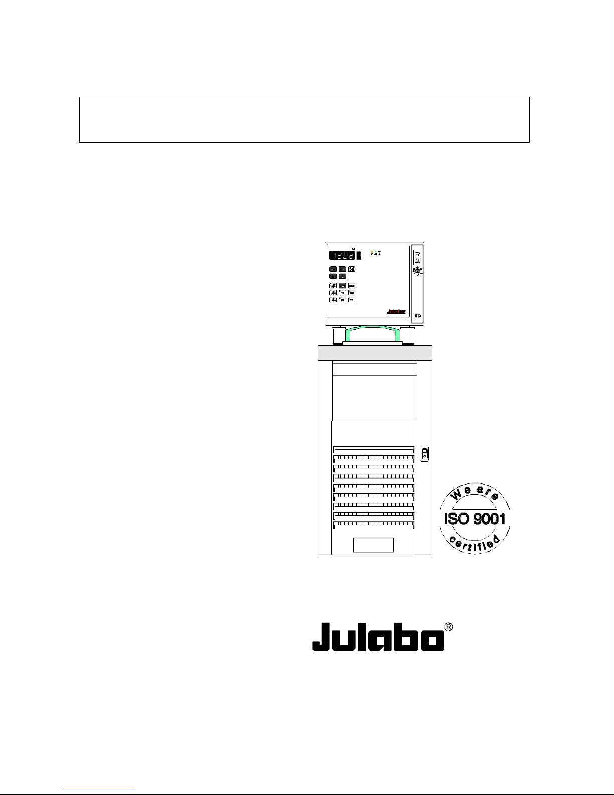
Refrigerated and Heating Circulators
FS18-HD
F25-HD
F26-HD
F32-HD
F33-HD
F34-HD
F33-SD
• with proportional cooling capacity control
FP40-HD / SD
FP45-HD / SD
FP50-HD / SD
Changes without prior notification reserved
1.953.2420BU6 02/03
JULABO USA, Inc.
754 Roble Road, Suite 180
Allentown, PA 18103
(610) 231-0250 (610) 231-0260
EMAIL us: info @ julabo.com
ONLINE Catalog: www.julabo.com
Page 2
2
Congratulations!
You have made an excellent choice.
JULABO thanks you for the trust you have placed in us.
This operating manual has been designed to help you gain an understanding of the principles of operating
and possibilities of our circulators. For optimum utilization of all functions, we recommend that you
thoroughly study this manual prior to beginning operation.
Safety Warnings
Take care your unit is operated only by qualified persons.
Make sure you read and understand all instructions and safety precautions listed in this manual before
installing or operating your unit. If you have any questions concerning the operation of your unit or the
information in this manual, contact JULABO.
Performance of installation, operation, or maintenance procedures other than those described in this
manual may result in a hazardous situation and may void the manufacturer's warranty.
Transport the unit with care. Sudden jolts or drops may cause damages in the interior of the unit.
Observe all warning labels.
Never remove warning labels.
Never operate damaged or leaking equipment.
Never operate the unit without bath fluid in the bath.
Always turn off the unit and disconnect the mains cable from the power source before performing any
service or maintenance procedures, or before moving the unit.
Always empty the bath before moving the unit.
Never operate equipment with damaged mains power cables.
Refer service and repairs to a qualified technician.
In addition to the safety warnings listed above, warnings are posted throughout the
manual. These warnings are designated by an exclamation mark inside an equilateral
triangle. Read and follow these important instructions. Failure to observe these
instructions can result in permanent damage to the unit, significant property damage,
personal injury or death.
Printed in Germany
Page 3

3
TABLE OF CONTENTS
1. OPERATING CONTROLS AND FUNCTIONAL ELEMENTS.................................. 4
2. QUALITY MANAGEMENT SYSTEM........................................................................... 6
3. UNPACKING AND CHECKING .................................................................................. 6
4. DESCRIPTION .............................................................................................................. 6
5. PREPARATIONS .......................................................................................................... 7
5.1. Installation................................................................................................................ 7
5.2. Bath liquids and tubing........................................................................................... 7
5.3. Filling / draining....................................................................................................... 9
5.4. Temperature application to external systems....................................................10
6. OPERATING PROCEDURES................................................................................... 12
6.1. Power connection.................................................................................................12
6.2. Switching on - Start/Stop .....................................................................................12
6.3. Setting the temperatures .....................................................................................14
6.4. Warning functions .................................................................................................15
6.5. Setting the safety temperature (with shutdown function) ..................................16
6.6. Internal / external control.......................................................................................17
6.7. PID control parameters........................................................................................ 18
7. MENU FUNCTIONS.................................................................................................... 19
7.1. ATC - Absolute Temperature Calibration..........................................................20
7.2. Id - Identification.................................................................................................... 21
7.3. h - Heater capacity ...............................................................................................22
7.4. r - Remote..............................................................................................................22
7.5. br - Baud rate ........................................................................................................ 23
7.6. P - Parity................................................................................................................23
7.7. H - Handshake...................................................................................................... 23
7.8. Sb - Stand-By........................................................................................................ 23
7.9. Pr - Programmer type ..........................................................................................23
7.10. Ad - Address .......................................................................................................... 24
7.11. Signal level RS232/RS485...................................................................................24
8. TROUBLESHOOTING GUIDE / ERROR MESSAGES..........................................25
9. SAFETY RECOMMENDATIONS..............................................................................27
10. ELECTRICAL CONNECTIONS.................................................................................28
11. REMOTE CONTROL .................................................................................................. 31
11.1. Setup for remote control........................................................................................31
11.2. Communication with a PC or a superordinated data system ...........................31
11.3. List of commands...................................................................................................33
11.4. Status messages / error messages..................................................................... 36
12. MAINTAINING THE COOLING PERFORMANCE...................................................38
13. CLEANING THE UNIT, MAINTENANCE..................................................................39
14. TECHNICAL SPECIFICATIONS ............................................................................... 40
15. WARRANTY CONDITIONS ........................................................................................ 44
Page 4
Operating controls and functional elements
4
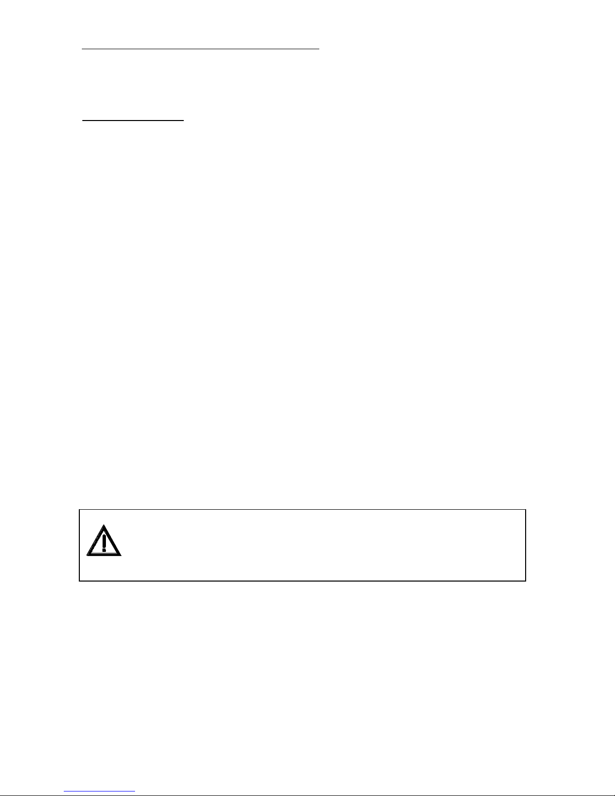
1. Operating controls and functional elements
1a/1b Mains power switch, illuminated
Circulator/Cooling machine
2 Start / stop key
3 Working temperature T1
4 Working temperature T2
5 High temperature warning limit
6 Low temperature warning limit
7 Safety temperature
8 Adjustable excess temperature protection
(safety temperature)
9 Display of internal/external actual value
10 Control type: internal/external control
11 Control parameters Xp, Tn, Tv
12 MULTI-DISPLAY (LED) temperature indication
Indicator lightsExt - external actual value (ext Pt100)
Xp, Tn, Tv - control parameters
Eprog - analog programmer signal
RS232 - remote control with a PC
Indicator light - Alarm
Indicator light - Cooling (not operational)
Indicator light - Heating
13 Cursors left/right
14 Edit keys (increase/decrease setting)
15 Enter key (store/quitting the audible signal)
19 Drain tap with drain port
Page 5

5
Rear
20 RS232
RS485
Interface RS232/RS485
21 REG+E-PROG
Programmer input and temperature recorder output
22a/22b
Connector: control cable of JULABO refrigerated circulator
23 STAND-BY
Stand-by input (for external emergency switch-off)
24 ALARM
Alarm output (for external alarm signal)
25
Connector for external measurement and control sensor
26
Connectors for solenoid valve and/or supplementary pump
230 V / 115 V
27
Fuses M 1.25 A / M 2.5 A (for connectors 26)
28a/28b
Mains fuses: Circulator
Cooling machine
29a/29b Mains power cable with plug: Circulator/Cooling machine
30 + 31
Pump connectors suction pump pressure pump
33
Selector dial for cooling machine (only on F25, F34)
Position „1“ for operation with circulator
34 Built-in mains outlet for connection of circulator
Only for water cooled models: Cooling water OUTLET and INLET
Page 6

Quality Management System
6
2. Quality Management System
The JULABO Quality Management System:
Development, production and distribution of temperature application instruments for
research and industries conform to the requirements according to DIN EN ISO
9001:1994-08.
Certificate Registration No. QA 051004008.
3. Unpacking and checking
Unpack the circulator and accessories and check for damages incurred during transit. These should be
reported to the responsible carrier, railway, or postal authority, and a request for a damage report
should be made. These instructions must be followed fully for us to guarantee our full support of your
claim for protecting against loss from concealed damage. The form required for filing such a claim will be
provided by the carrier.
4. Description
The JULABO refrigerated circulators employ a circulator head and a cooling machine with bath tank,
and have been designed for heating and cooling of liquids in a bath tank.
Besides the cooling aggregate, the main functional elements are the heater, circulation pump, and control
electronics. An electronic proportional temperature control (PID characteristic) adapts the heat supplied
to the thermal requirements of the bath.
Setting is rapid and simple using the keypad with its easy to learn symbols. Keypad is splash-proof,
easily cleaned and ergonomically designed.
The microprocessor technology allows four temperature values to be stored and indicated on the
MULTI-DISPLAY (LED): working temperatures T1 and T2, high and low temperature warning limits.
The safety value for excess temperature protection, a safety installation independent from the control
circuit, is adjustable on the front with simultaneous indication on the MULTI-DISPLAY (LED).
The RS232/RS485 port permits modern process engineering without additional interface, directly online, from the circulator to your application equipment.
Besides the digital interface, additionally analog connectors are provided, such as for Pt100 external
sensor, analog programmer input, temperature recorder output and others.
The circulator conforms to the safety requirements specified by DIN 12 876 (safety class III), as well as
DIN 58 966, and the guideline for first voltage range EN 61010.
Page 7

7
5. Preparations
5.1. Installation
• Place the unit in an upright position.
• Keep at least 20 cm of open space on the front and rear venting
grids.
• Do not set up the unit in the immediate vicinity of heat sources
and do not expose to sun light.
• Before operating the unit after transport, wait about one hour
after setting it up. This will allow any oil that has accumulated
laterally during transport to flow back down thus ensuring
maximum cooling performance of the compressor.
• Only for water cooled models:
Ensure circulation of cooling water by connecting the tubing to
cooling water inlet and outlet on the rear of the refrigerated
circulator.
Cooling water connectors: ½"
Cooling water see page 43
5.2. Bath liquids and tubing
Carefully read the safety data sheet of the bath liquid used, particulary with
regard to the fire piont!
If Ethanol is used, only supervised operation is possible.
• Recommended bath liquids:
Bath liquids Temperature range Flash point fire point
Thermal M +50 °C ... 170 °C >275 °C >320 °C
Thermal H +50 °C ... 250 °C >280 °C >350 °C
Thermal HY -60 °C ... 50 °C >62 °C >110 °C
Ethanol (C2H5OH) -100°C bis 0 °C 12 °C
deionized water 5 °C bis 80 °C
ATTENTION: The maximum permissible viscosity is 30 mm2 x s
-1.
Page 8

Preparations
8
Please contact JULABO before using other than recommended bath liquids.
JULABO takes no responsibility for damages caused by the selection of an
unsuitable bath liquid.
Unsuitable bath liquids are liquids which e.g.
• are very highly viscous
(much higher than 30 mm2 x S-1 at the respective working temperature)
• have corrosive characteristics or
• tend to cracking.
Order No. Bath liquid
8 940 100
8 940 101
8 940 102
8 940 103
8 940 104
8 940 105
Thermal M
Thermal M
Thermal H
Thermal H
Thermal HY
Thermal HY
10 liters container
5 liters container
10 liters container
5 liters container
10 liters container
5 liters container
• Recommended tubing:
Temperature range
CR tubing
Viton tubing
Metal tubing
-20 °C to +120 °C
-50 °C to +200 °C
-100 °C to +350 °C
Page 9
9
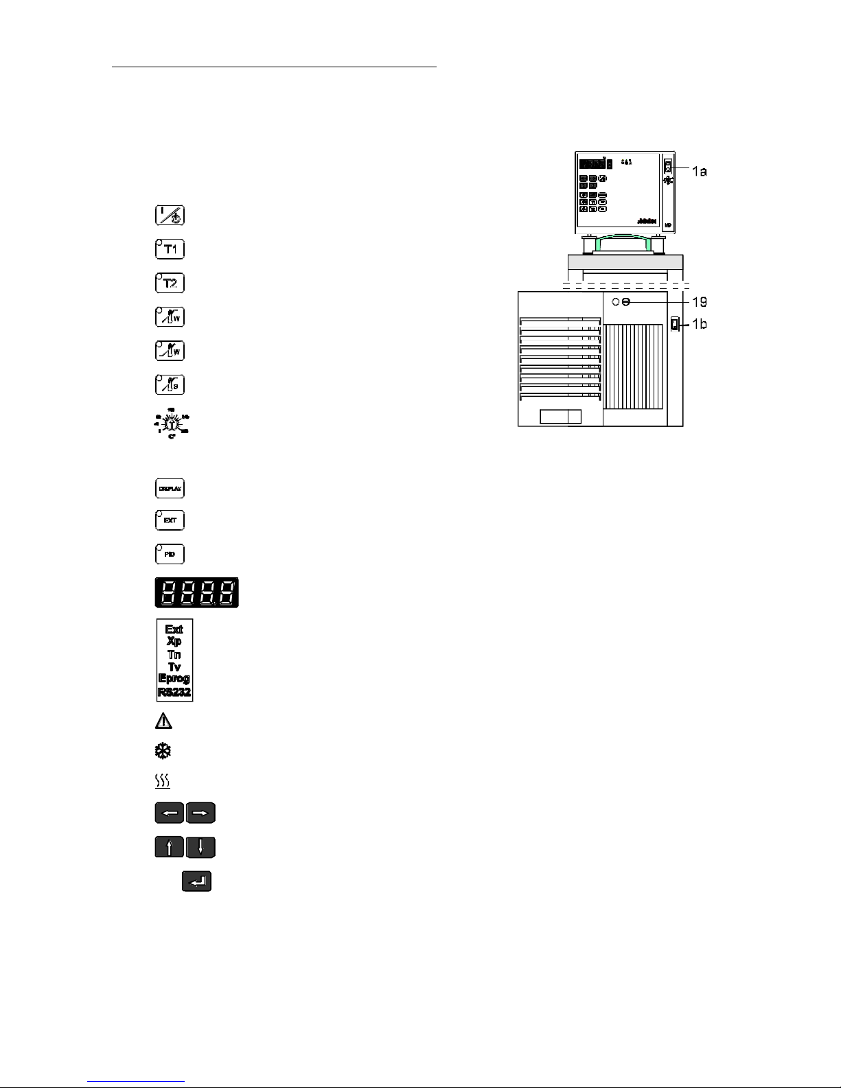
5.3. Filling / draining
Filling
Take care that no liquid enters the interior of the circulator.
• Recommended maximum filling level with water as bath liquid:
25 mm below the tank rim
• Recommended maximum filling level with bath oils:
40 mm below the tank rim
After filling, immerse the samples in the bath or place the lid on the
bath, in case the opening is not to be used.
FS18
• Recommended maximum filling level is 5 mm.
Note:
When switching the circulator on, the bath liquid may lie below the
required minimum level due to liquid pumped into the external
system.
ATTENTION: The volume of bath oils will increase due to thermal expansion
when the bath temperature rises.
Exercise CAUTION when emptying hot bath liquids!
19
Draining
• Turn off the circulator and cooling machine.
• Hold the venting grid, pull out and remove.
• Slide a short piece of tube onto the drain port and hold it into a
pail.
• Unscrew the drain tap (19) and empty the unit completely.
• Tighten the drain tap.
Store and dispose the used bath liquid according to the laws
for environmental protection.
Page 10
Preparations
10
5.4. Temperature application to external systems
Temperature application to external, closed systems
The circulator is used for temperature application to external,
closed systems (loop circuit) with simultaneous temperature
application in the circulator bath.
• Unscrew the M 16 x 1 collar nuts on the pump connectors
(pressure pump , suction pump ) with a 19 mm (3/4")
wrench and remove the sealing disks. Using the collar nuts,
screw on the tubing connection fittings (for tubing 8 mm or 12
mm in diameter) delivered with the unit and tighten firmly.
• Push on the tubings, and secure with tube clamps.
• Attach the tubings to the connectors of the external closed
system, e.g., an instrument with a pressure-resistant temperature
jacket or a temperature coil, and fasten with tube clamps to
prevent slipping.
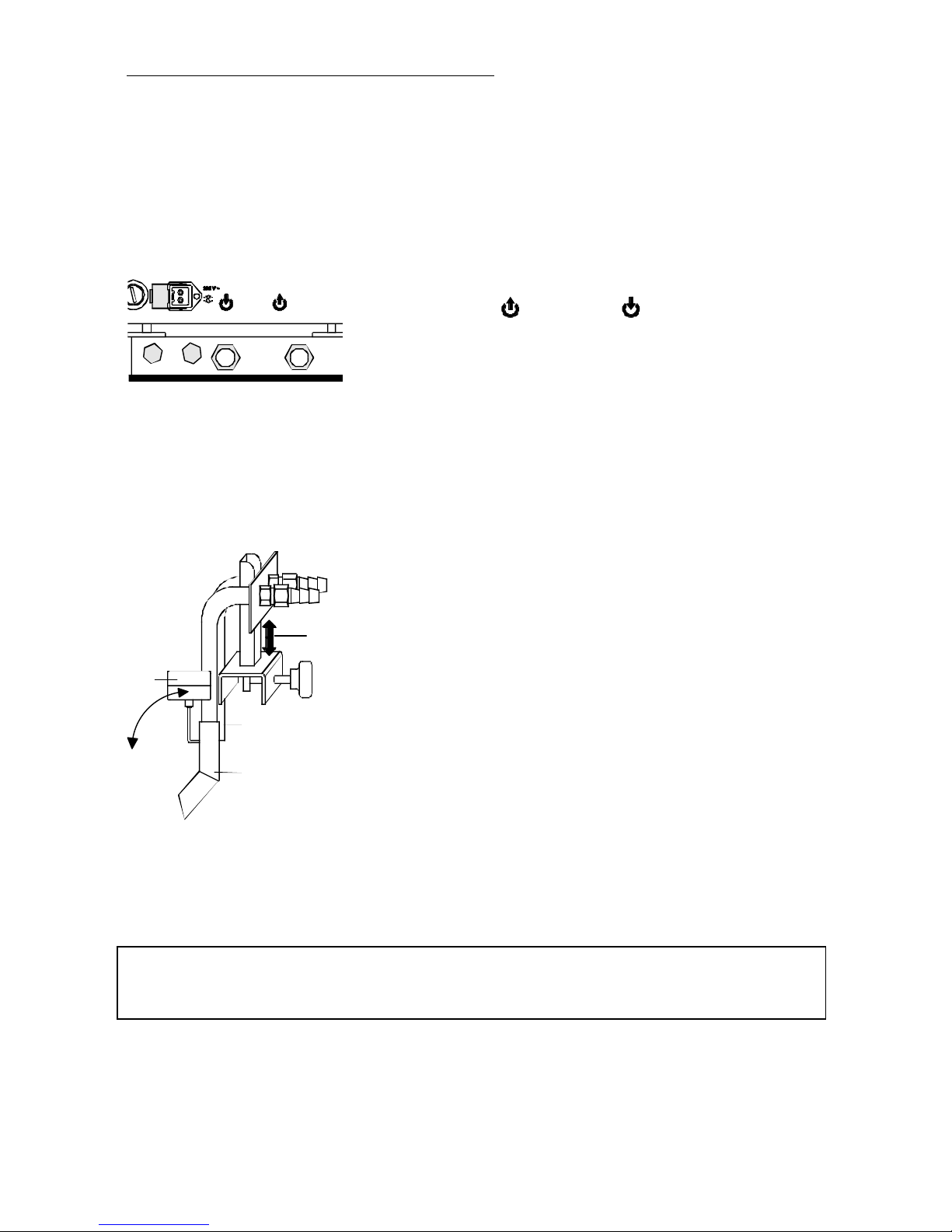
Temperature application to external, open systems
K
S
D
H
S = Suction pump connection
D = Pressure pump connection
K = Float
H = Height adjustment
These circulators are equipped with both a pressure and suction
pump for external temperature application in open systems.
Differing flow rates of the pressure and suction pumps should be
compensated. To maintain a constant liquid level, the JULABO
"D+S" Level Adapter is recommended for the external bath tank.
The flow rate of the pressure pump will be then regulated by a
built-in float device. The liquid level may be changed by a height
adjustment on the "D+S" Level Adapter.
Order No. 8 970 410 "D+S" Level Adapter
When working at temperatures below 0 °C and using the "D+S" Level Adapter do
not use oil as the bath liquid. Condensing air will result in the formation of ice and
thus affects the function of the float.
Page 11
11
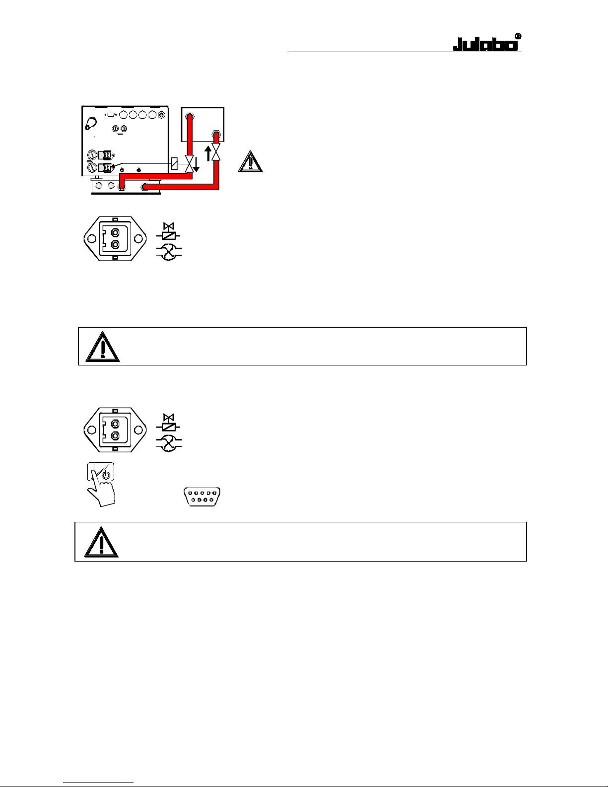
Return flow safety device
If the liquid levels in the circulator bath and the external system are
at different heights, overflowing must be prevented after the power
has been turned off.
Flood hazard!
For this reason, solenoid valves for loop circuit or shut-off valves
can be integrated in the loop circuit.
Connect the valve (230 V / 115 V) to the connector (26).
Order No. Description
8 980 701 Solenoid valve for loop circuit up to +100 °C
8 970 456 Shut-off valve (suitable up to +90 °C)
8 970 457 Shut-off valve (suitable up to +250 °C)
Fasten tubing to prevent slipping.
Supplementary pump
Both connectors (26) may be used for operating supplementary
pumps.
Control (switching on/off) is effected by presssing the start/stop
key or via the digital interface with the start/stop command.
Check to make sure that the line voltage matches the supply voltage specified
on the identification plate (230 V or 115 V).
Page 12
Operating procedures
12
6. Operating procedures
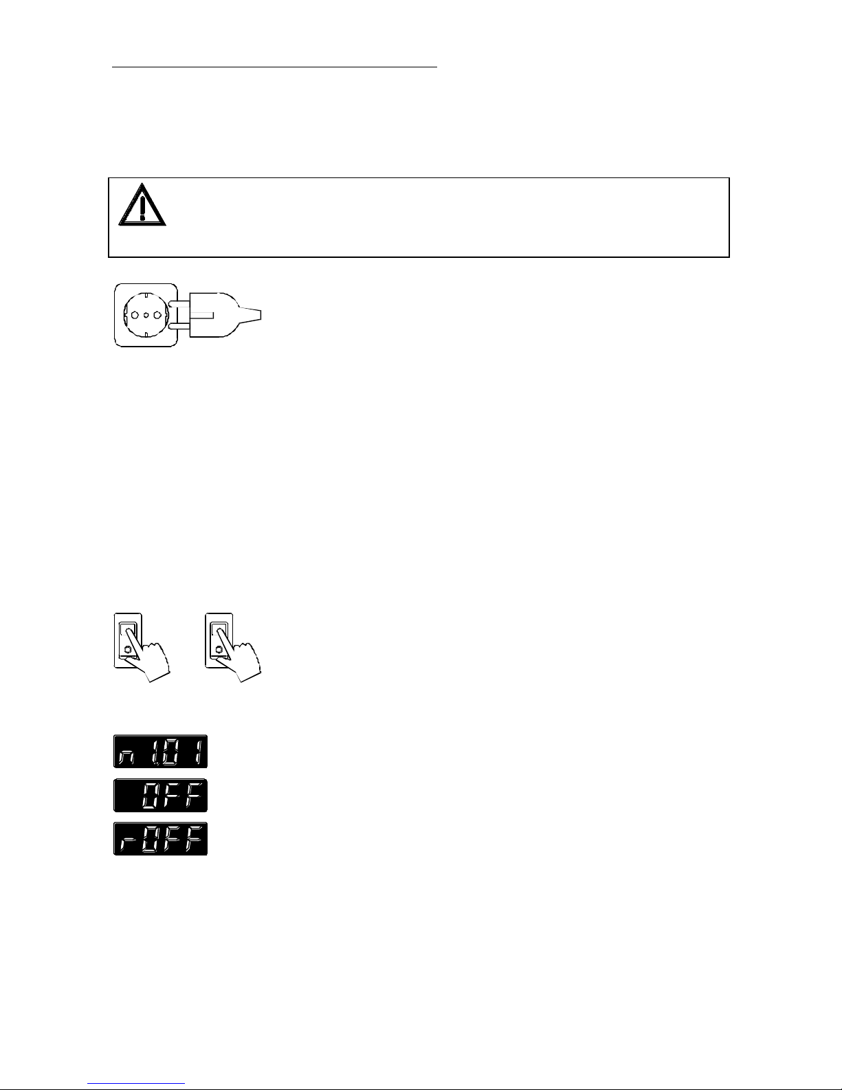
6.1. Power connection
Connect the unit only to grounded mains power socket!
Do not use 2-pole adapters!
We disclaim all liability for damage caused by incorrect line voltages or if the
unit has not been connected to ground.
Check to make sure that the line voltage matches the supply
voltage specified on the identification plate.
Deviations of ±10 % are permissible
• Connect the circulator with mains power cable (29a) to the
mains outlet (34).
• Connect the control cable (22) between the connectors (22a,
22b).
• Connect the refrigerated circulator with mains power cable
(29b) to the mains socket.
6.2. Switching on - Start/Stop
Switching on:
Circulator and cooling machine may be turned on and off with
separate mains switches. The integrated control light will illuminate
to indicate that power has beeen applied.
The unit performs a self-test. All segments of the 4-digit MULTIDISPLAY (LED) and all indicator lights will illuminate.
Then the software version (example: n 1.01) appears. The display
"OFF" or "r OFF" indicates the unit is ready to operate (stand-by
mode).
The circulator enters the operating mode activated before switching
the circulator off:
keypad control mode (manual operation) or
remote control mode (operation via personal computer).
Page 13

13
Start:
• Press the start/stop key.
- The MULTI-DISPLAY (LED) indicates the actual bath
temperature. (example: 21.0 °C)
- An illuminated indicator light in the "T1" or "T2" key indicates
the activated working temperature.
Stop:
• Press the start/stop key.
The MULTI-DISPLAY (LED) indicates the message "OFF".
The unit also enters the safe operating state "OFF" or "r OFF after a mains power
interruptance. In case of manual operation, the start/stop key has to be pressed to
restart operation. The temperature values which were entered via the keypad of the
circulator remain in memory.
If the circulator is operated in remote control mode, the order to start and all values
which have to be adjusted, must be resent via interface by the personal computer.
NOTE:
The circulator has been configured and supplied by JULABO according to N.A.M.U.R.
recommendations. This means for the start mode, that the unit must enter a safe operating state after a
power failure (non-automatic start mode). This safe operating state is indicated by „OFF“ or „rOFF“,
resp. on the MULTI-DISPLAY (LED). A complete shutdown of the main functional elements such as
heater and circulation pump is effected simultaneously.
Should such a safety standard not be required, the AUTOSTART function (automatic start mode) may
be activated, thus allowing the start of the circulator directly by pressing the mains power switch or using
a timer.
Automatic / non-automatic start mode
Activating/deactivating AUTOSTART
Press enter and the start/stop key at the same
time,
and turn on the circulator with the mains power switch.
For a short while the MULTI-DISPLAY indicates the effective start
mode:
AUTOSTART on.
AUTOSTART off.
Page 14
Operating procedures
14
Warning:
For supervised or unsupervised operation with the AUTOSTART function, avoid
any hazardous situation to persons or property.
The circulator does no longer conform to N.A.M.U.R. recommendations.
Take care you fully observe the safety and warning functions of the circulator.
If the setpoint is given via the serial interface, no AUTOSTART is possible.
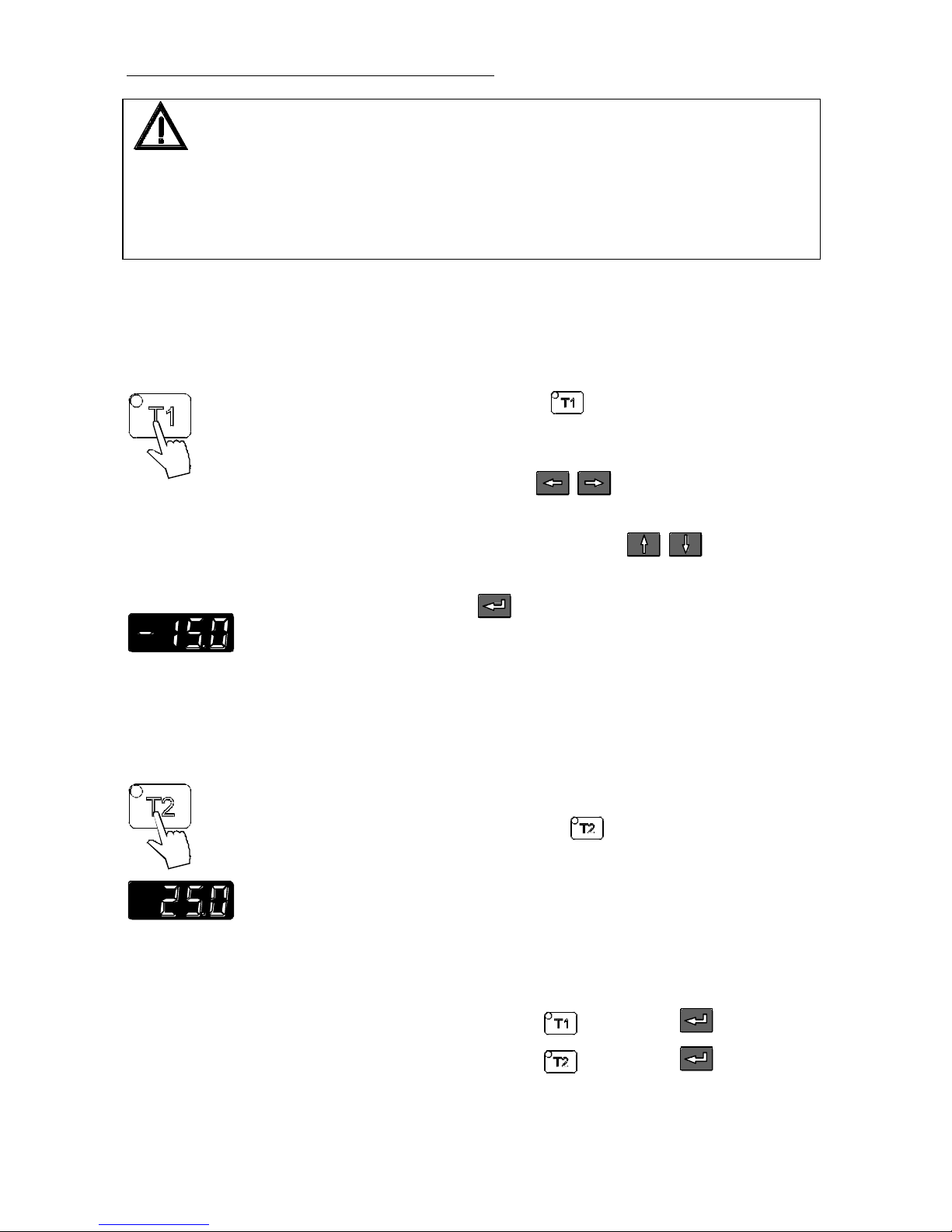
6.3. Setting the temperatures
Setting the working temperature "T1":
Press the setpoint key
.
The indicator light blinks and the value previously set appears
on the MULTI-DISPLAY (LED).
Use the cursor keys to move left or right on the
display until the numeral you wish to change is blinking.
Use the increase/decrease arrows to change the
selected numeral (-, 0, 1, 2, 3, ... 9).
Press enter to store the selected value
(example: -15.0 °C).
The working temperature is maintained constant after a short heatup time (e. g. -15.0 °C).
Setting the working temperature "T2":
Press the setpoint key .
Same procedure
as with "T1"
(example: 25.0 °C).
Selecting the working temperature:
• Press the setpoint key and then enter .
• Press the setpoint key and then enter .
Page 15

15
6.4. Warning functions
)) )) ))
More protection for your samples in the bath!
An audible signal sounds in intervals when the actual temperature
value exceeds one of the set limits (patented function).
Setting the high temperature limit:
Press the key .
The indicator light blinks and the value previously set appears
on the MULTI-DISPLAY (LED).
Use the cursor keys to move left or right on the
MULTI-DISPLAY (LED) until the numeral you wish to
change is blinking.
Use the edit keys to increase or decrease the
numeral value (-, 0, 1, 2, 3, ... 9).
Press enter to store the value
(example: -13.0 °C).
Setting the low temperature limit:
Press the key
.
Follow the instructions
for
(example: -17.0 °C).
Note:
The warning functions will only be triggered when the actual bath temperature, after start
from the „OFF“ or „rOFF“ mode, lies within the set limits for 3 seconds.
t
°C
39
37
35
20
50
Page 16

Operating procedures
16
6.5. Setting the safety temperature (with shutdown function)
!
+
⇒
(excess temperature protection)
• Press the key to indicate the safety temperature value on the
MULTI-DISPLAY (LED) and using a screwdriver
simultaneously turn the setting screw to the desired value
(example: 50 °C).
Setting range: 0 °C to 320 °C
in 2 °C steps
This safety installation is independent of the control circuit. When
the temperature of the bath liquid has reached the safety
temperature, a complete shutdown of the heater and pump is
effected.
The alarm is indicated by optical and audible signals (continuous
tone) and on the MULTI-DISPLAY (LED) appears the error
message "Error 14".
Cancel the alarm state (see page 26).
Recommendation:
Set the safety temperature at 5 to 10 °C above the working
temperature setpoint.
The excess temperature protection should be set at least 20 °C below the fire
point of the bath liquid used.
In the event of wrong setting there is a fire hazard!
We disclaim all liability for damage caused by wrong settings!
Page 17

17
6.6. Internal / external control
ext. Pt100
The circulator is suitable for temperature control in the internal bath
as well as in the external system (loop circuit).
• Press the key
in operating state „OFF“ to select the
control type.
Internal control:
• The indicator light in the key is not illuminated.
External control:
Setup:
• Connect a Pt100 sensor to the socket on the rear of the
circulator, if necessary perform a calibration using the Atc2
function (see page 21) and then securely fix the sensor in the
external system.
• Press the key to switch to external control (example: T1).
The indicator light in the key illuminates.
• Press the start/stop key .
The MULTI-DISPLAY (LED) automatically indicates the
temperature value registered by the Pt100 sensor
(example: -15.0 °C).
• Switch the display to indicate the internal/external value:
Press the key to indicate the temperature value registered
by the internal measurement sensor
(example: -15.8 °C).
Place the external sensor into the bath medium and securely fix the sensor.
Page 18

Operating procedures
18
6.7. PID control parameters
When performing an identification for the controlled system
(temperature application system) (see page 21), the control
parameters Xp, Tn, and Tv will be automatically determined and
stored.
Indication of control parameters:
Press the key
to indicate the parameters in succession:
1) Xp parameter (example 4.0 °C).
2) Tn parameter (example 160 s).
3) Tv parameter (example 20 s).
Each parameter may be manually set via the keypad to allow
optimum control performance.
Setting the control parameters::
Press the key and select the parameter.
Use the cursor keys to move left or right on the
display until the numeral you wish to change is blinking.
Use the increase/decrease arrows to change the
selected numeral (-, 1, 2, 3, ... 9).
Press enter to store the selected value
(example: Xp parameter set to 4.2 °C)
Optimization instructions for the PID control parameters:
The heat-up curve reveals inappropriate control settings (example:
working temperature T1).
optimum setting
Page 19

19
Inappropriate settings may produce the following heat-up curves:
Xp too low
Tv/Tn too low
Xp
or
Tv too high
Tv/Tn
or
Xp too high
7. Menu functions
Set the parameters for the circulator via the configuration level.
Selecting/exiting the configuration level.
• Simultaneously press the cursor key and
enter .
• The first menu item is"Atc0".
Selecting and setting menu items.
• Select the menu items in succession by pressing the cursor keys
.
• Set the parameter for each menu item using the edit
keys and store with enter .
Page 20

Menu functions
20
7.1. ATC - Absolute Temperature Calibration
• With the edit keys select
"Atc1" (internal sensor) or
“Atc2“ (external sensor) and then press enter .
Circulator (TT)
Atc1:
Serves to compensate a temperature difference that might occur
between circulator (TT) and a defined measuring point (TM) in the
bath tank because of physical properties.
Note:
Setting of Atc1 is recommended for temperature applications in the
circulator bath.
Measuring point (TM)
• The difference temperature is determined (ΔT = TM - TT)
and stored as correcting factor (example ΔT = -0.2 °C) for Atc1.
Excample: Setting the correcting factor.
• Use the cursor keys and the edit keys to set
the correcting factor (example -0.20 °C) and then press enter .
• Simultaneously press the cursor key and enter to exit the
configuration level.
•
Measuring point (TM)
The temperature on the measuring point rises to a temperature of
-15.0 °C and is indicated on the MULTI-DISPLAY (LED).
Note:
The correcting factor always affects the actual working temperature, even
if this is set via the interface.
Recommendation:
In case a calibrated temperature measuring instrument is used, the ATC
function allows the circulator to be used as testing instrument according to
ISO 9000.
Page 21

21
ext. Pt100
Circulator (TT)
External sensor (T
Pt100
)
Atc2:
Serves to calibrate a connected Pt100 sensor.
• Immerse the Pt100 sensor in the external bath and wait until a
constant bath temperature (example: 50 °C) is maintained.
• Press the key to indicate the temperature value registered by the
external Pt100 sensor (T
Pt100
) instead of the temperature from the
circulator (TT).
• Determine the difference temperature and store the value as correcting
factor for Atc2.
(example: ΔT = TT - T
Pt100
= -1.2 °C)
The ATC function stays activated until resetting to 00.00 °C.
7.2. Id - Identification
When performing an identification for the controlled system
(temperature application system), the control parameters Xp, Tn,
and Tv (see page 18) will be automatically determined and stored.
Possible parameters:
0 - No identification
The control parameters ascertained during the last identification
are used for control purposes.
1 - Single identification
The circulator performs a single identification of the controlled
system after start.
After the identification process the parameter is reset to “0“.
When the circulator is powered down by pressing the power
switch off and on again, the parameter is automatically set to
„1“.
2 - Continual identification
The circulator performs an identification of the controlled
system whenever a new setpoint is to be reached.
NOTE: Use this setting only when the temperature application
system changes permanently.
Page 22

Menu functions
22
Note:
Requirement for an identification of the controlled system:
• The circulator must heat to a setpoint temperature at least 10 °C
above the previous setpoint.
When the adjusted control parameters Xp, Tn and Tv are too high,
this requirement may not be given with respect to on how much the
setpoint temperature has to change. In this case, prior to carrying
out an identification in the „OFF“ state, set the control parameters
to lower values.
Recommended setting for internal control:
Xp = 1.0 °C
Tn = 80 s
Tv = 8 s
7.3. h - Heater capacity
The heater capacity is adjustable.
The heater capacity data indicated in the technical specifications
conforms to a setting of 100 %.
Possible parameters:
from 10 % to 100 % in 10 % steps.
7.4. r - Remote
Remote control for the circulator can be performed via the serial
RS232/RS485 interface or the analog “REG+E-PROG“
connector.
Possible parameters:
0 - Keypad control
RS232
REG+E-PROG
RS485
1 - Remote control via the serial RS232 interface by a PC or
superordinated data system.
2 - Control by a programmer via the analog“REG+E-PROG“
connector (see menu item Pr - programmer type).
3 - Remote control via the serial RS485 interface by a PC or
superordinated data system.
Page 23

23
7.5. br - Baud rate
Baudrate of the serial interface
Possible parameters:
1200 bauds
2400 bauds
4800 bauds
9600 bauds
7.6. P - Parity
Parity bits of the serial interface
Possible parameters:
0 = no parity
1 = odd parity
2 = even parity
7.7. H - Handshake
Handshake of the serial interface
Possible parameters:
0 = XOn/XOff, software handshake
1 = RTS/CTS, hardware handshake
7.8. Sb - Stand-By
STAND-BY
External stand-by for emergency switch-off
Possible parameters:
0 = stand-by input is ignored
1 = stand-by input is active
(connector see page 30)
7.9. Pr - Programmer type
REG+E-PROG
For adapting the programmer input to the connected programmer.
Possible parameters:
0 = voltage input 0 to 10 V
1 = current input 0 to 20 mA
2 = current input 4 to 20 mA
The voltage and current input ranges are fixed and correspond to a
temperature range from -100 °C to +400 °C.
Press the setpoint key
and the setpoint value (in °C) appears
on the MULTI-DISPLAY (LED).
Page 24

Menu functions
24
7.10. Ad - Address
For determination of a circulator address for operation via the
serial RS485 interface.
(example: Ad32)
Possible parameters: 0 to 99
In case a superordinated data system controls several circulators at
one time, commands are directed to the corresponding instrument
using the respective circulator address.
The address must stand in front of each command.
7.11. Signal level RS232/RS485
The serial interfaces RS232 and RS485 use different output levels.
When the circulator is used in keypad control mode and values are
to be called off via the serial interface at the same time, use this
menu item for setting the desired signal level.
Possible parameters: c232
c485
If under the menu item „Remote“ (see page 22) one of the serial
interfaces is selected, the signal level is automatically set.
Page 25

25
8. Troubleshooting guide / Error messages
!
+
Whenever the microprocessor electronics registers a failure, a complete
shutdown of the heater and circulation pump is performed. The alarm light
" " illuminates and a continuous signal tone sounds.
• The circulator is operated without bath liquid, or the liquid level is
insufficient. Replenish the bath tank with the bath liquid.
• Tube breakage has occured (insufficient filling level due to excessive bath
liquid pumped out). Replace the tubing and replenish the bath tank with
the bath liquid.
• The float is defect (e. g., because damaged in transit). Repair by
authorized JULABO service personnel.
• During the self-test after switch-on a short-circuit is registered between
pin 2 and pin 4 of the control cable or the control cable is interrupted
during operation.
Reconnect the cable or eliminate the short-circuit.
• Cable of the working temperature sensor interrupted or short-circuited.
• Defect of the working or safety temperature sensor.
Working temperature and safety sensors report a temperature difference
of more than 25 °C.
• Other errors.
• Error in A/D converter.
• Safety sensor defect.
• The safety temperature value lies below the working temperature
setpoint.
Set the safety temperature to a higher value.
• External control selected, but external Pt100 sensor not connected.
• Heating circuit interrupted.
• Heating circuit short-circuited.
• Defective alarm relay.
Page 26

Troubleshooting guide / Error messages
26
Warnings without a complete shutdown of the unit: E 21 to E 24
• Cooling of the condenser is affected. Clean air-cooled condenser.
Check the flow rate and cooling water temperature on water-cooled
condenser.
• Compressor stage 1 does not work.
• Compressor stage 2 does not work.
Cooling compressor overload protection
The motor of the cooling compressor is equipped with an overload
protector, which will be activated by excessive temperature in the capsule
or by excessive current consumption.
Causes for motor disconnection:
- poor air circulation
- small distance to walls
- dirt accumulated on condenser
- high ambient temperature
- switch-off and on for short intervals
• Excess temperature on compressor stage 1.
• Excess temperature on compressor stage 2.
This message appears every 10 seconds as long as the compressor is not
switched on although requested by the circulator.
After a short cooling interval, the motor will be automatically
reconnected and the message "E xx" no longer appears.
• Control cable of the refrigerated circulator short-circuited during self-test.
⇒
Press enter
to quit the audible signal.
After eliminating the malfunction, press the mains power switch off and on
again to cancel the alarm state.
If the unit cannot be returned to operation, contact an authorized JULABO
service station.
• Special message "Configuration Error"
The configuration of the circulator does not conform to its present use.
• Press enter to automatically perform a single modification of the
configuration.
Then contact an authorized JULABO service station.
Page 27

27
• Special message "EOFF" see page 30.
Disturbances that are not indicated.
Pump motor overload protection
• The pump motor is protected against overloading. After a short cooling
interval, the motor will automatically start running.
Fuses
• The mains fuses on the rear of the unit may easily be exchanged as shown
on the left.
Circulator: Fine fuses T12.5A or M 2.5 A, dia. 5 x 20 mm
Cooling machine: Fine fuses T10A, dia. 5 x 20 mm
Only use fine fuses with a nominal value as specified.
9. Safety recommendations
Follow the safety recommendations to prevent damage to persons or property. Further,
the valid safety instructions for working places must be followed.
• Connect the unit only to a grounded mains power socket!
• Observe the fire point of the bath medium used.
The excess temperature protection should be set at least 20 °C below the fire point.
• Pay attention to the thermal expansion of bath oil during heating to avoid overflowing
of the liquid.
• Prevent water from penetrating into the hot bath oil.
• Some parts of the bath cover and the pump connections may become extremely
warm during continuous operation. Therefore, exercise particular caution when
touching these parts.
• Exercise caution when emptying hot bath liquids!
• Observe the limited working temperature range when using plastic bath tanks.
• Employ suitable connecting tubing.
• Make sure that the tubes are securely attached.
• Avoid sharp bends in the tubing, and maintain a sufficient distance from surrounding
walls.
• Regularly check the tubing for material defects (e.g. for cracks).
• Before cleaning the unit, disconnect the power plug from the mains socket.
Page 28

Safety recommendations
28
Recommendation:
When you have finished the application, it is recommended to keep on circulating the
liquid in the bath or the external system for some time. Simultaneously set the working
temperature to +20 °C to allow the temperature in the system to decrease slowly.
Thus fractional over-heating of the bath liquid is prevented.
Page 29

29
10. Electrical connections
RS232
RS485
Serial RS232/RS485 interface (20)
This port can be used to connect a computer with an RS232 or RS485
cable for remote control of the circulator.
Pin assignments: RS232
Pin 2 RxD Receive Data
Pin 3 TxD Transmit Data
Pin 5 0 VD Signal GND
Pin 6 DTR Data terminal ready
Pin 7 RTS Request to send
Pin 8 CTS Clear to send
Pin assignments: RS485
Pin 3 A
Pin 5 0 VD Signal GND
Pin 8 B
Pins 1, 2, 4, 6, 7, 9 Reserved - do not use!
Interface correspondence:
Circulator Computer Circulator Computer
9-pole 25-pole 9-pole 9-pole
Pin 2 RxD ⇔ Pin 2 TxD Pin 2 RxD ⇔ Pin 3 TxD
Pin 3 TxD ⇔ Pin 3 RxD Pin 3 TxD ⇔ Pin 2 RxD
Pin 5 GND ⇔ Pin 7 GND Pin 5 GND ⇔ Pin 5 GND
Pin 6 DTR ⇔ Pin 6 DSR Pin 6 DTR ⇔ Pin 6 DSR
Pin 7 RTS ⇔ Pin 5 CTS Pin 7 RTS ⇔ Pin 8 CTS
Pin 8 CTS ⇔ Pin 4 RTS Pin 8 CTS ⇔ Pin 7 RTS
RS232 interface cable 9-pin / 9-pin, 2,5 m Order No.: 8 980 073
ext. Pt100
1
4
2
3
Shield
Plug
Look on
soldering side.
Pt100
Connector for external Pt100 sensor (25)
Pin assignment:
Pin Signal
1 Current+
2 Voltage+
3 Voltage 4 Current-
The shield of the connecting cable is electrically connected to the plug
housing and the sensor tube.
Use shielded cables only.
Page 30

Electrical connections
30
REG+E-PROG
Programmer input / Temperature recorder output (21)
Pin Signal
1 Output: temperature external sensor 0 to 10 V
1)
2 Output: temperature internal sensor 0 to 10 V
1)
(1) 0 V = -100 °C, 10 V = 400 °C)
3 GND for outputs 0 V
4 Input: programmer
see „Pr - progammer type“, page 23
5 Output: setpoint (dependent from the adjustment made
under menu item „Pr - progammer type“)
at Pr 0 0 to 20 mA
2)
at Pr 1 0 to 20 mA
2)
(2) 0 mA = -100 °C, 20 mA = 400 °C)
at Pr 2 4 to 20 mA
3)
(3) 4 mA = -100 °C, 20 mA = 400 °C)
6 GND for programmer 0 V
Use shielded cables only.
Control output (22)
The connector may be used for control of JULABO refrigerated
circulators or as output for alarm messages.
Pin assignment:
Pin Signal
1 +24 V ( max. current 25 mA)
2 0 V
3 Alarm relay
4 Reserved - do not use!
5 Cooling pulse
Circuit:
Operation = relay powered
Alarm = relay not powered
Use shielded cables only.
Page 31

31
STAND-BY
STAND-BY input (23)
(for external emergency switch-off)
Pin assignment: Pin Signal
1 not used
2 5 V / DC
3 0 V
Activate the stand-by input:
• Under menu item Sb, set the parameter to 1 (see page 23).
• Connect an external contact 'AK' (e.g. for emergency switch-off) or
an alarm contact of the superordinated system.
• In case the connection between Pin 2 and Pin 3 is interrupted by
opening the contact 'AK', a complete shutdown of the circulation
pump and heater is effected, and the unit enters the operating state
"OFF".
• As long as the contact is open, a flashing „E“ is preceding the message
„OFF“ on the MULTI-DISPLAY (LED).
If the contact is closed, the circulator may be started by pressing the
start key .
Use shielded cables only.
ALARM
Alarm output (24)
(for external alarm signal)
This potential-free change-over contact is activated in case of an alarm
when pins 2 and 3 are connected.
Switching capacity max. 30 W / 40 VA
Switching voltage max. 125 V∼/−
Switching current max. 1 A
Use shielded cables only.
Control connector (26)
To be used as return flow safety device with solenoid valves (see page
11) and/or for supplementary pumps.
Line voltage: 230 V∼ / max. 1.25 A
115 V∼ / max. 2.5 A
Page 32

Remote control
32
11. Remote control
11.1. Setup for remote control
RS232
RS485
Interface parameters for the circulator are adjusted via the
configuration level.
(Selecting and setting menu items, see page 20)
• Set menu item REMOTE to „1“.
Factory settings of the serial interface:
REMOTE 0 = keypad control mode
BAUDRATE 48 = 4800 bauds
PARITY 2 = even parity
HANDSHAKE 1 = Protocol RTS/CTS
(Hardware handshake)
Data bits 7
Stop bit 1
Like all parameters which can be entered through the keypad, interface
parameters are stored in memory even after the circulator is turned off.
11.2. Communication with a PC or a superordinated data system
Suitable terminal programs for communicating with a PC are:
MS-Windows - TERMINAL.EXE (included with MS-Windows).
MS-DOS - Procomm Plus, Datastrom Technologies.
MS-DOS - Norton Utilities.
Page 33

33
If the circulator is put into remote control mode via the
configuration level, the display will read
"r OFF" = REMOTE STOP.
The circulator is now operated via the computer.
In general, the computer (master) sends commands to the
circulator (slave). The circulator sends data (including error
messages) only when the computer sends a query.
After a power interruption in case of remote control the order to
start and all values which have to be adjusted, must be resent via
the interface from the personal computer.
AUTOSTART is not possible.
A transfer sequence consists of:
• address (RS485 interface only)
• command
• space (⇔, Hex: 20)
• parameter (the character separating decimals in a group is the
period)
• end of file (↵; Hex: 0D)
The commands are divided into in and out commands.
• in commands: asking for parameters to be displayed
• out commands: setting parameters
The out commands are valid only in remote control mode.
When the RS485 interface is used, the three-digit instrument
address stands in front of each command.
(example: address Ad32 = A032)
Examples:
Command to set the working temperature T1 to 55.5 °C:
out_sp_00 ⇔ 55.5↵
A032_out_sp_00 ⇔ 55.5↵
Command to ask for the working temperature T1:
in_sp_00↵
A032_in_sp_00↵
Response from the circulator:
55.5↵
A032_55.5↵
Page 34

Remote control
34
11.3. List of commands
When the RS485 interface is used, the instrument address stands in front of each command (Axxx_).
in commands: Asking for parameters or temperature values to be displayed.
Command Parameter Response of circulator
version none Number of software version (V X.xx)
status none Status message, error message (see below 36).
in_pv_00 none Actual bath temperature.
in_pv_01 none Heater wattage being used (%).
in_pv_02 none Temperature value registered by the external Pt100 sensor.
in_pv_03 none Temperature value registered by the safety sensor.
in_sp_00 none Working temperature "T1"
in_sp_01 none Working temperature "T2"
in_sp_03 none
High temperature warning limit "
".
in_sp_04 none
Low temperature warning limit "
".
in_sp_05 none Setpoint temperature of the external programmer
(socket 21 - REG+E-PROG) .
in_hil_00 none Max. cooling capacity (%).
in_hil_01 none Max. heater capacity (%).
in_mode_01 none Selected working temperature:
0 = "T1".
1 = "T2".
in_mode_02 none Identification type:
0 = no identification
1 = single identification
2 = continual identification
Page 35

35
Command Parameter Response of circulator
in_mode_03 none Type of the programmer input:
0 = Voltage 0 V to 10 V
1 = Current 0 mA to 20 mA
2 = Current 4 mA to 20 mA
in_mode_04 none Internal/external temperature control:
0 = Temperature control in the circulator bath.
1 = Temperature control with external Pt100 sensor.
in_mode_05 none Circulator in Stop/Start condition:
0 = Stop
1 = Start
in_par_01 none Time constant of the external bath.
in_par_02 none Internal slope.
in_par_03 none Time constant of the internal bath.
in_par_04 none Bandwidth limit (max. difference between the temperatures in the
internal bath and external system).
in_par_05 none Ratio for max. cooling capacity versus max. heating capacity.
in_par_06 none Xp control parameter of the internal controller.
in_par_07 none Tn control parameter of the internal controller.
in_par_08 none Tv control parameter of the internal controller.
in_par_09 none Xp control parameter of the cascade controller.
in_par_10 none Proportional portion of the cascade controller.
in_par_11 none Tn control parameter of the cascade controller.
in_par_12 none Tv control parameter of the cascade controller.
Page 36

Remote control
36
out commands: Setting parameters or temperature values.
Command Parameter Response of circulator
out_mode_01 0 Use working temperature "T1" *
out_mode_01 1 Use working temperature "T2" *
out_mode_02 0 No identification.
Temperature control by using the stored parameters.
out_mode_02 1 Single identification of controlled system after the next start.
out_mode_02 2 Continual identification of controlled system whenever a new
setpoint is to be reached.
out_mode_04 0 Temperature control of internal bath.
out_mode_04 1 External control with Pt100 sensor.
out_mode_05 0 Stop the circulator = r OFF.
out_mode_05 1 Start the circulator.
out_sp_00 xxx.x Set working temperature "T1".
out_sp_01 xxx.x Set working temperature "T2".
out_sp_03 xxx.x
Set high temperature warning limit .
out_sp_04 xxx.x
Set low temperature warning limit .
out_hil_01 xxx Set the desired maximum heater capacity (10 % to 100 %)
(* see "Note" on page 20)
Page 37

37
Command Parameter Response of circulator
out_par_04 xxx Bandwidth limit during external control.
Setting the maximum difference between the temperatures
in the internal bath and external system.
out_par_05 xxx Ratio between max. cooling capacity versus max. heater capacity
(0...0.99).
out_par_06 xxx Xp control parameter of the internal controller.
out_par_07 xxx Tn control parameter of the internal controller.
out_par_08 xxx Tv control parameter of the internal controller.
out_par_09 xxx Xp control parameter of the cascade controller.
out_par_10 xxx Proportional portion of the cascade controller.
out_par_11 xxx Tn control parameter of the cascade controller.
out_par_12 xxx Tv control parameter of the cascade controller.
11.4. Status messages / error messages
The circulator sends data (including error messages) only when the computer sends a query.
Status messages Description
00 MANUAL STOP Circulator in "OFF" state.
01 MANUAL START Circulator in keypad control mode.
02 REMOTE STOP Circulator in "r OFF" state.
03 REMOTE START Circulator in remote control mode.
Page 38

Remote control
38
Error messages Description
-01 LOW LEVEL ALARM Low liquid level alarm
-02 REFRIGERATOR ALARM Control cable of the refrigerated circulator or
MVS solenoid valve controller short-circuited or
interrupted.
-03 EXCESS TEMPERATURE WARNING
High temperature warning " ".
-04 LOW TEMPERATURE WARNING
Low temperature warning " ".
-05 WORKING SENSOR ALARM Working temperature sensor short-circuited or
interrupted.
-06 SENSOR DIFFERENCE ALARM Sensor difference alarm.
Working temperature and safety sensors report a
temperature difference of more than 25 °C.
-07 I2C-BUS ERROR Internal error when reading or writing the I2C bus.
-08 INVALID COMMAND Invalid command.
-09 COMMAND NOT ALLOWED IN
CURRENT OPERATING MODE
Invalid command in current operating mode.
-10 VALUE TOO SMALL Entered value too small.
-11 VALUE TOO LARGE Entered value too large.
-12 TEMPERATURE MEASUREMENT
ALARM
Error in A/D converter.
-13 WARNING : VALUE EXCEEDS
TEMPERATURE LIMITS
Value lies outside the adjusted range for the high
and low temperature warning limits. But value is
stored.
-14 TEMPERATURE/LEVEL ALARM
Safety temperature alarm
-15 EXTERNAL SENSOR ALARM External control selected, but external Pt100
sensor not connected.
-16 TRIAC/RELAY CONNECTION OPEN Heating circuit interrupted.
-17 TRIAC SHORTED Heating circuit short-circuited.
-18 RELAY SHORTED Defective alarm relay.
Page 39

39
Error messages Description
-20 WARNING: CLEAN CONDENSOR
OR CHECK COOLING WATER
CIRCUIT OF REFRIGERATOR
Cooling of the condenser is affected. Clean aircooled condenser.
Check the flow rate and cooling water
temperature on water-cooled condenser.
-21 WARNING: COMPRESSOR STAGE 1
DOES NOT WORK
Compressor stage 1 does not work.
-22 WARNING: COMPRESSOR STAGE 2
DOES NOT WORK
Compressor stage 2 does not work.
-23 WARNING: HIGH TEMPERATURE
ON COMPRESSOR STAGE 1
Excess temperature on compressor stage 1.
-24 WARNING: HIGH TEMPERATURE
ON COMPRESSOR STAGE 2
Excess temperature on compressor stage 1.
-25 REFRIGERATOR WARNING Error in the cooling machine.
-26 WARNING: STAND-BY PLUG IS
MISSING
External stand-by contact is open.
Stand-by input - see pages 23 and 30.
-30 CONFIGURATION ERROR:
CONFIRM BY PRESSING <ENTER>
ON CIRCULATOR
The configuration of the circulator does not
conform to its present use.
Press enter to automatically perform a
single modification of the configuration.
(Then contact an authorized service station).
12. Maintaining the cooling performance
To maintain the full cooling performance, clean the condenser from time
to time.
• Switch off the unit, disconnect mains power cable.
• Hold the venting grid, pull out and remove.
• Clean the ribbed condenser with a vacuum cleaner.
• Replace the venting grid.
• Switch on the unit.
Page 40

Cleaning the unit, Maintenance
40
13. Cleaning the unit, Maintenance
Before cleaning the unit, disconnect the power plug from the mains socket!
Prevent humidity from entering into the circulator.
For cleaning the bath tank and the immersed parts of the circulator, use low surface
tension water (e.g., soap suds).
Clean the outside of the unit using a wet cloth and low surface tension water
The circulator is designed for continuous operation under normal conditions. Periodic
maintenance is not required.
The tank should be filled only with a bath liquid recommended by JULABO. To avoid
contamination, it is essential to change the bath liquid from time to time.
Repairs
Before asking for a service technician or returning a JULABO circulator for
repair, please contact an authorized JULABO service station.
When returning a unit, take care of careful and adequate packing. JULABO is not
responsible for damages that might occur from insufficient packing.
JULABO reserves the right to carry out technical modifications with repairs for
providing improved performance of a unit.
Page 41

41
14. Technical specifications
HD SD
Temperature selection digital
via keypad indication on MULTI-DISPLAY (LED)
remote control via personal computer indication on monitor
Temperature indication MULTI-DISPLAY (LED)
Resolution °C 0.01 from -9.99 °C to +99.99 °C
°C 0.1 from ≤ -10.0 °C to ≥ +100.0 °C
Absolute Temperature Calibration:
ATC1 °C ±3
ATC2 °C ±9
Temperature control PID
Working temperature sensor Pt100
Safety temperature sensor Pt100
Heater wattage W 2000 (at 230 V) 2000 (at 230 V)
W 1000 (at 115V) 1000 (at 115V)
Pressure pump:
pressure, max. psi at 0 liters 5 8.2
discharge, max. Lpm at 0 psi 20 24
Suction pump:
suction, max. psi at 0 liters 3.2 5.8
discharge, max. Lpm at 0 psi 14 16
Electrical connections:
Computer interface RS232/RS485
Programmer input -100 °C to 400 °C = 0 - 10 V or 0 - 20 mA or 4 - 20 mA
Temperature recorder output 0 - 10 V (0 V = -100 °C, 10 V = 400 °C)
0 - 20 mA (0 mA = -100 °C, 20 mA = 400 °C)
4 - 20 mA (4 mA = -100 °C, 20 mA = 400 °C)
Stand-by input
Alarm output 24 to 0 V DC / max. 25 mA
External measurement and control sensor - Pt100
Control connectors for solenoid valves or supplementary pump - 230 V or 115 V / max. 1.25 A
Mains power connection V/ Hz 230 / 50 230 / 50
(±10 %) V/ Hz or 115 / 60 or 115 / 60
Total power consumption (at 230 V) Watts 2400 2400
(at 115 V) Watts 1400 1400
All measurements have been carried out at:
rated voltage and frequency ambient temperature: 20 °C
Technical changes without prior notification reserved.
Page 42

Technical specifications
42
FP40-HD/-SD FP45-HD/-SD
Working temperature range °C -38 ... 200 -42 ... 200
Temperatur stability °C ±0.01 ±0.01
Cooling capacity °C +20 0 -20 -30 +20 0 -20 -40
(bath liquid: ethanol) Watts 680 500 320 180 850 700 420 80
Refrigerant R404a R404a
Ambient temperature °C 5... 40 5... 40
Mains power connection (±10 %) V/ Hz 230 / 60 or 230 / 50 230 / 60
Total power consumption Watts 3000/3050 3100/3150
Bath opening (WxD)/ bath depth cm 23x14/20 23x26/20
in. 9x5½ /8 9x10/8
Filling volume liters 9 ... 16 18 ... 26
Overall dimensions (WxDxH) cm 37x46x70/75 38x58x68/73
Weight Lbs 99/106 117
FP50-HD/-SD
Working temperature range °C -50 ... 200
Temperatur stability °C ±0.01
Cooling capacity °C +20 0 -20 -40 -50
(bath liquid: ethanol) Watts 900 800 500 160 50
Refrigerant R507
Ambient temperature °C 5... 40
Mains power connection (±10 %) V/ Hz 230 / 60 or 230 / 50
Total power consumption Watts 3100/3150
Bath opening (WxD)/ bath depth cm 18x12/15
in. 7x5/6
Filling volume liters 5,5 ... 8
Overall dimensions (WxDxH) cm 42x50x71/76
Weight Lbs 128
Page 43

43
FS18-HD F25-HD F26-HD
Working temperature range °C -30 ... 150 -25 ... 200 -25 ... 200
Temperatur stability °C ±0.01 ±0.01 ±0.01
Cooling capacity °C +20 0 -20 +20 0 -20 +20 0 -20
(bath liquid: ethanol) Watts 460 340 150 260 200 60 260 200 60
Refrigerant R134a R134a R134a
Ambient temperature °C 5... 40 5... 40 5... 40
Mains power connection V/ Hz 230 / 50 230 / 50 230 / 50
(±10 %) V/ Hz or 115 / 60 or 115 / 60 or 115 / 60
Total power consumption Watts 2770 or 1770 2600 or 1600 2600 or 1600
Bath opening (WxD)/ bath depth cm 12x14/12 12x14/12
in. 5x5 ½ /6 5x5 ½ /6
Filling volume liters 1.7 ... 3 3 ... 4,5 3 ... 4,5
Overall dimensions (WxDxH) cm 31x43x65 23x42x63 42x42x44
Weight Lbs 86 73 71
F32-HD F33-HD/SD F34-HD
Working temperature range °C -32 ... 200 -30 ... 200 -30 ... 150
Temperatur stability °C ±0.01 ±0.01 ±0.01
Cooling capacity °C +20 0 -20 -30 +20 0 -20 +20 0 -20
(bath liquid: ethanol) Watts 380 340 150 50 500 320 120 450 320 140
Refrigerant R134a R134a R134a
Ambient temperature °C 5... 40 5... 40 5... 40
Mains power connection V/ Hz 230 / 50 230 / 50 230 / 50
(±10 %) V/ Hz or 115 / 60 or 115 / 60 or 115 / 60
V/ Hz 230 / 60
Total power consumption Watts 2770 or 1770 2750 or 1750 2680 or 1680
2800 (SD)
Bath opening (WxD)/ bath depth cm 18x12/12 23x14/ 20 24x30/ 15
in. 7x5 /6 9x5 ½ /8 9 ½ x12 /8
Filling volume liters 5.5 ... 8 12 ... 16 14 ... 20
Overall dimensions (WxDxH) cm 31x43x65 37x46x70/75 38x58x63
Weight Lbs 84 90 / 99 108
Page 44

Technical specifications
44
Safety Installations (DIN 12876)
Excess temperature protection adjustable from 0 to 320 °C
Low liquid level protection float switch
Safety class III
Supplementary safety installations:
High temperature warning function optical + audible (in intervals)
Low temperature warning function optical + audible (in intervals)
Supervision of the working sensor plausibility control
Reciprocal sensor monitoring between
working and safety sensors difference >25 °C
Alarm indication optical + audible (continuous tone)
Standards:
EMC regulations EN 61326
Guideline for first voltage range EN 61010-1, EN 61010-2-010
Pressure equipment directive EN 378
Only for water-cooled models:
Cooling water pressure (IN / OUT ) max. 6 bar
Difference pressure (IN - OUT ) 3.5 to 6 bar
Cooling water temperature <20 °C
Quality of cooling water:
pH at 25 °C 7 to 8.5
Suspended matter <30 mg/l
Size of suspended matter max. 0.1 mm
Growth of algae not permissible
Page 45

45
15. Warranty conditions
JULABO USA, Inc. warrants its products against defects in material or in workmanship, when used
under appropriate conditions and in accordance with appropriate operating instructions for a period of
no less than
TWO (2) YEARS
or a maximum of ten thousand hours (10,000), whichever comes first, from the date of delivery of the
products. To avoid forfeiture of the warranty and to allow JULABO to be of continuing service to the
scientific community, the record of the purchase is required to be returned to JULABO or one of its
authorized representatives within 30 days of receipt of equipment.
JULABO’s sole obligation shall be to repair or to replace at JULABO’s option, F.O.B. its plant or
locally, without charge, any part(s) that prove defective within the warranty period, providing the
customer notifies JULABO promptly and in writing of any such defect. Compensation for labor other
than Julabo’s employees will not be JULABO’s obligation. Part(s) replacement does not constitute an
extension of the original warranty period.
JULABO will not assume responsibility for unauthorized product modifications, or for repairs,
replacements, or modifications negligently or otherwise improperly made or performed by persons other
than JULABO employees or authorized representatives.
JULABO MAKES NO WARRANTY OR MERCHANTABILITY, FITNESS FOR A
PARTICULAR PURPOSE, OR ANY OTHER WARRANTY, EXPRESS OR IMPLIED, AS TO
THE DESIGN, SALE, INSTALLATION, OR USE OF ITS PRODUCTS, AND SHALL NOT BE
LIABLE FOR CONSEQUENTIAL DAMAGES RESULTING FROM THE USE OF ITS
PRODUCTS.
While JULABO’s personnel or that of its authorized representatives are available to advise customers
concerning general applications of all manufactured products, oral representations are not warranties
with respect to particular applications, and should not be relied upon if inconsistent with product
specifications or the terms stated herein.
All glassware, such as reference thermometers, etc, are expressly excluded from this warranty
declaration.
In any event, the terms and conditions contained in JULABO’s formal sales contracts shall be controlling
and any change must be in writing and signed by an authorized executive of JULABO USA, Inc.
 Loading...