

Page 1

1.951.4806-V4 11/17
www.julabo.com
Operating Manual
Recirculating Cooler
F250 F500 F1000
JULABO GmbH
77960 Seelbach / Germany
Tel. +49 (0) 7823 / 51-0
Fax +49 (0) 7823 / 24 91
info.de@julabo.com
Page 2
Temperature control devices for research and industry are developed,
9001
This product has been tested to the requirements of CAN/CSA-C22.2
requirements.
Congratulations!
You have made an excellent choice.
JULABO thanks you for the trust you have placed in us.
This operating manual has been designed to help you gain an understanding of the operation
and possible applications of our circulators. For optimal utilization of all functions, we
recommend that you thoroughly study this manual prior to beginning operation.
The JULABO Quality Management System
produced, and distributed according to the requirements of ISO
and ISO 14001.Certificate Registration No. 01 100044846
For F250 device
No. 61010-1, second edition, including Amendment 1, or a later
version of the same standard incorporating the same level of testing
Unpacking and inspecting
Unpack the circulator and accessories and inspect them for possible transport damage.
Damage should be reported to the responsible carrier, railway, or postal authority, and a
damage report should be requested. These instructions must be followed fully for us to
guarantee our full support of your claim for protecting against loss from concealed damage.
The form required for filing such a claim will be provided by the carrier.
Printed in Germany Changes without prior notification reserved
Important: keep original operating manual for future use
2 1.951.4806-V4
Page 3

F250, F500, F1000
CONTENT
1. Intended use ................................................................................................................ 4
2. Operator responsibility – Safety recommendations ....................................................... 4
3. Handling......................................................................................................................... 5
3.1. Appropriate operation ............................................................................................ 5
3.2. Use ........................................................................................................................ 5
3.3. Disposal ................................................................................................................ 6
4. Technical specifications ................................................................................................. 7
4.1. F250 ...................................................................................................................... 7
4.2. F500 ...................................................................................................................... 8
4.3. Warning functions and safety installations .......................................................... 10
4.4. Materials of Construction of the wetted Parts ...................................................... 11
5. Safety Notes ........................................................................................................... 13
5.1. Description of the safety notes ............................................................................ 13
5.2. Explanation of other notes ................................................................................... 13
5.3. Safety instructions ............................................................................................... 14
6. Moving up and connect ................................................................................................ 15
6.1. Transportation and site conditions ....................................................................... 15
6.2. Tubing ................................................................................................................. 16
7. Operating controls and functional elements ................................................................. 18
7.1. F250 .................................................................................................................... 18
7.2. F500 .................................................................................................................... 20
8. Operating procedures .................................................................................................. 22
8.1. Bath fluids ........................................................................................................... 22
8.2. Power connection ................................................................................................ 23
8.3. Filling ................................................................................................................... 23
8.4. Switching on / Start - Stop ................................................................................... 24
8.5. Setting the temperatures ..................................................................................... 24
8.6. Timer function...................................................................................................... 25
8.6.1. Setting the time ................................................................................................ 25
8.6.2. Timer operation ................................................................................................ 25
8.7. AUTOSTART ON / OFF ...................................................................................... 26
9. Safety installations ....................................................................................................... 27
9.1. Excess temperature protection ............................................................................ 27
9.2. Low level protection ............................................................................................. 27
10. Troubleshooting guide / Error messages ..................................................................... 28
11. Cleaning / repairing the unit ......................................................................................... 30
11.1. Draining ............................................................................................................... 31
12. Warranty conditions ..................................................................................................... 32
12.1. EC-Declaration of Conformity .............................................................................. 33
1.951.4806-V4 3
Page 4
Intended use
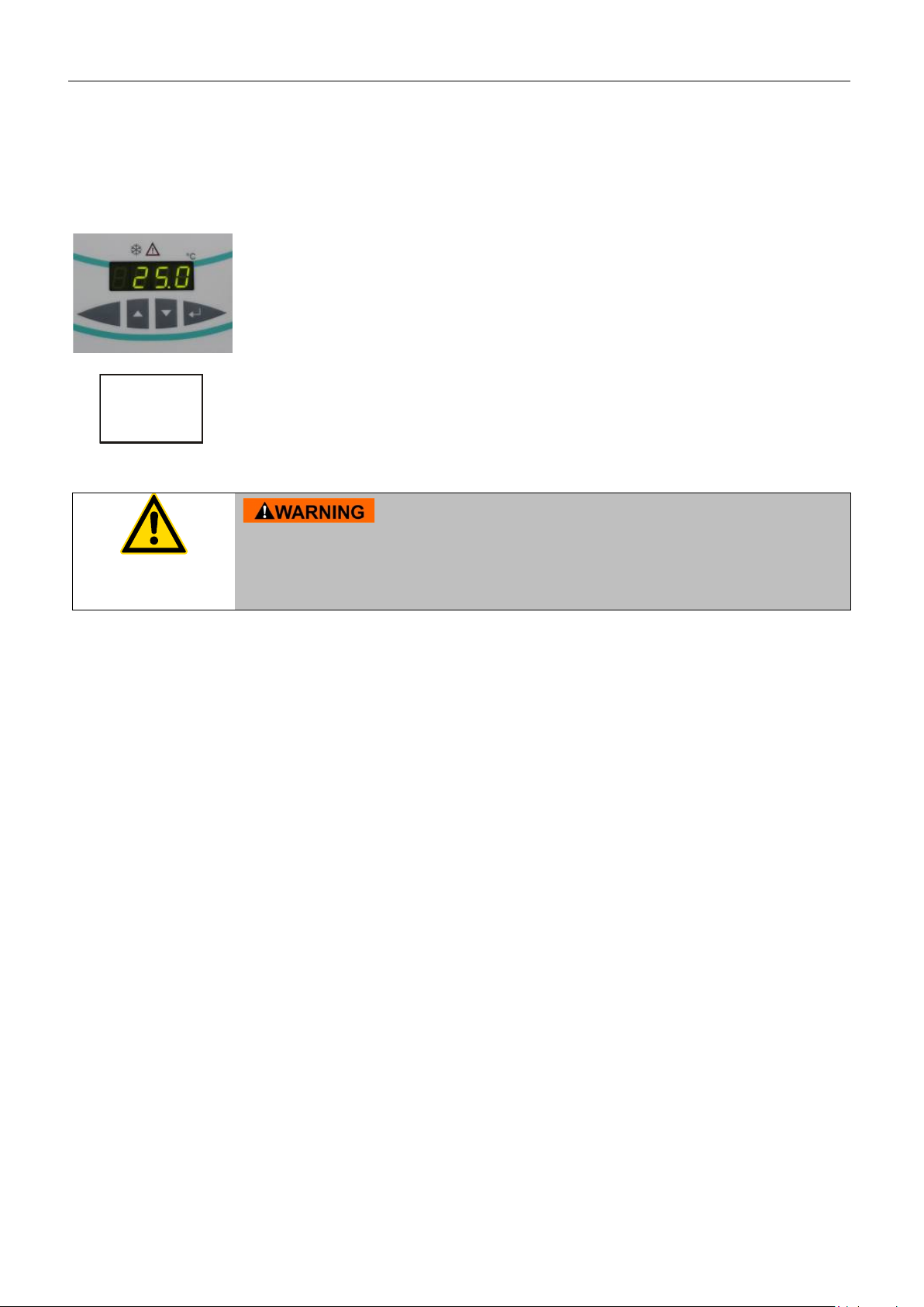
PID1
The recirculating coolers are operated via the splash-proof keypad.
technical products.
1. Intended use
JULABO recirculating coolers have been designed for temperature application to specific
fluids.
The pump connections can be used for cooling applications in an external circuit at a constant
temperature.
The implemented microprocessor technology allows to set and to
store the setpoint that can be indicated on the LED temperature
display.
The PID temperature regulation is used to withdraw heat from the
bath fluid by means of the cooling machine and to automatically
regulate the required need.
Health hazards caused by the bath fluid.
JULABO recirculating coolers are not conceived for direct temperature
application to food and luxury articles or pharmaceutical and medico-
Direct temperature application means: Unprotected contact of the object with the bath
medium (bath fluid).
2. Operator responsibility – Safety recommendations
The products of JULABO ensure safe operation when installed, operated, and maintained
according to common safety regulations. This section explains the potential dangers that may
arise when operating the circulator and also specifies the most important safety precautions to
preclude these dangers as far as possible.
The operator is responsible for the qualification of the personnel operating the units.
Make sure that the persons who operate the chillers, are trained in this work.
The personnel operating the units should be regularly instructed about the dangers
involved with their job activities as well as measures to avert these dangers.
Make sure all persons tasked with operating, installing, and maintaining the unit have read
and understand the safety information and operating instructions.
When using hazardous materials or materials that could become hazardous, the circulator
may be operated only by persons who are absolutely familiar with these materials and the
circulator. These persons must be fully aware of possible risks.
4 1.951.4806-V4
Page 5

F250, F500, F1000
Contact: JULABO GmbH
77960 Seelbach / Germany
The unit is not for use in explosive atmosphere.
If you have any questions concerning the operation of your unit or the information in this
manual, please contact us!
+49 7823 51-0 info.de@julabo.com
Eisenbahnstraße 45
+49 7823 2491 www.julabo.com
3. Handling
You have received a product designed for industrial use. Nevertheless, avoid strikes to the
housing, vibrations, damage to the operating-element panel (keypad, display), and
contamination.
Make sure the product is checked for proper condition regularly (depending on the
conditions of use).
Regularly check (at least every 2 years) the proper condition of the mandatory, warning,
prohibition and safety labels.
Make sure that the mains power supply has low impedance to avoid any negative effects
on instruments being operated on the same mains.
This unit is designed for operation in a controlled electromagnetic environment. This
means that transmitting devices (e.g., cellular phones) should not be used in the
immediate vicinity.
Magnetic radiation may affect other devices with components sensitive to magnetic fields
(e.g., monitors). We recommend maintaining a minimum distance of 1 m.
Permissible ambient temperature: max. 40 °C, min. 5 °C.
Permissible relative humidity: 50% (40 °C).
Do not store the unit in an aggressive atmosphere.
Protect the unit from contamination.
Do not expose the unit to sunlight.
3.1. Appropriate operation
Only qualified personnel is authorized to perform configuration, installation, maintenance and
repairs of the circulator.
Routine operation can also be carried out by untrained personnel who should however be
instructed by trained personnel.
3.2. Use
Fire hazard!
The bath can be filled with flammable materials. Fire hazard!
There might be chemical dangers depending on the bath medium used.
Observe all warnings for the used materials (bath fluids) and the respective instructions
(safety data sheets).
Insufficient ventilation may result in the formation of explosive mixtures. Only use the unit in
1.951.4806-V2 5
Page 6
Handling
or
Valid in EU countries
municipal waste is not permitted!
well ventilated areas. The unit is not for use in explosive atmosphere.
Only use recommended materials (bath fluids). Only use non-acid and non corroding
materials.
When using hazardous materials or materials that could become hazardous, the operator
must affix the enclosed safety labels (1 + 2) to the front of the unit so they are highly visible:
1
2a
2b
Danger area. Attention! Observe instructions.
(operating manual, safety data sheet)
Carefully read the user information prior to beginning operation.
Scope: EU
Carefully read the user information prior to beginning operation.
Scope: USA, NAFTA
3.3. Disposal
This unit contains the refrigerants R134a – at this time considered not to have any negative
effects on the ozone layer. However, during the long operating period of the unit, disposal
prescriptions may change. So only qualified personnel should take care of disposal.
See the current official journal of the European Union – WEEE directive.
Directive of the European Parliament and of the Council on waste electrical
and electronic equipment (WEEE).
This directive requires electrical and electronic equipment marked with a
crossed-out trash can to be disposed of separately in an environmentally
friendly manner.
Contact an authorized waste management company in your country.
Disposal with household waste (unsorted waste) or similar collections of
6 1.951.4806-V4
Page 7

4. Technical specifications
Recirculating Cooler
F250
Working temperature range
°C
-10 ... +40
Temperature stability
°C
±0.5
Temperature selection:
digital
via key pad
indication on LED-DISPLAY
Temperature indication:
LED-DISPLAY
Adjustment and display resolution
°C
0.1
Temperature control
PID 1
Temperature sensor
Pt 100
Excess temperature protection
85 °C - fixed value
Low liquid level protection
float switch
Circulating pump:
discharge, max.at 0 bar
l/min
15
pressure, max. at 0 Liters
bar
0.35
Filling level indicator
sight glass
Filling volume from ... to
Liters
1.7 ... 2.6
Dimensions (WxLxH)
cm
24x40x52
Weight
kg
27.0
Ambient temperature range
°C
5 ... 40
Return flow temperature max.
°C
80
Cooling compressor
1- stage / air cooled
Refrigerant
R134a
Cooling capacity
Medium: Mixture water-glycol
Mains power connection
V/ Hz
230 ±10 % / 50
Current draw (at 230 V)
A
3.0
Mains power connection
V/ Hz
230 ±10 % / 60
Current draw (at 230 V)
A
2.0
Mains power connection
V/ Hz
200 -5 %; +21 % / 50-60
Current draw (at 200 V / 50 Hz)
(at 200 V / 60 Hz)
A
A
2.0
2.0
Mains power connection
V/ Hz
115 ±10 % / 60
Current draw (at 115 V)
A
4.0
Mains power connection
V/ Hz
100 ±10 % / 50-60
Current draw (at 100 V / 50 Hz)
(at 100 V / 60 Hz)
A
A
5.0
5.0
4.1. F250
F250, F500, F1000
at 100 V / 60 Hz at 115 V / 60 Hz
at 200 V / 60 Hz at 230 V / 60 Hz
at 230 V / 50 Hz
at 100 V / 50 Hz at 200 V / 50 Hz
All measurements have been carried out at: rated voltage and frequency
ambient temperature: 20 °C. Technical changes without prior notification reserved.
°C
W
°C
W
+20 +15 +10 +5 0 -5 -10
250 240 220 210 180 90 60
+20 +15 +10 +5 0 -5 -10
220 210 195 185 170 80 40
1.951.4806-V4 7
Page 8

Technical specifications
Recirculating Cooler
F500
Working temperature range
°C
0 ... +40
Temperature stability
°C
±0.5
Temperature selection:
digital
via key pad
indication on LED-DISPLAY
Temperature indication:
LED-DISPLAY
Adjustment and display resolution
°C
0.1
Temperature control
PID 1
Temperature sensor
Pt 100
Excess temperature protection
85 °C - fixed value
Low liquid level protection
float switch
Circulating pump:
discharge, max.at 0 bar
l/min
24
pressure, max. at 0 Liters
bar
0.5
Filling level indicator
sight glass
Filling volume from ... to
Liters
5,0 ... 7,5
Dimensions (WxLxH)
cm
37,5x44x59
Weight
kg
34.0
Ambient temperature range
°C
5 ... 40
Return flow temperature max.
°C
80
Cooling compressor
1- stage / air cooled
Refrigerant
R134a
Cooling capacity
Mains power connection
V/ Hz
230 -10 %; +7 % / 50
Current draw (at 230 V)
A
3.0
Mains power connection
V/ Hz
230 ±10 % / 60
Current draw (at 230 V)
A
3.0
Mains power connection
V/ Hz
115±10 % / 60
Current draw (at 115 V)
A
6.0
Mains power connection
V/ Hz
100 -5 %; +10 % / 50-60
Current draw (at 100 V / 50 Hz)
(at 100 V / 60 Hz)
A
A
6.0
6.0
4.2. F500
at 230 V / 50 Hz
Medium: Mixture water-glycol
All measurements have been carried out at: rated voltage and frequency
ambient temperature: 20 °C
Technical changes without prior notification reserved.
°C
W
+20 +10 +5 0
500 400 300 250
8 1.951.4806-V4
Page 9

4.3. F1000
Recirculating Cooler
F1000
Working temperature range
°C
0 ... +40
Temperature stability
°C
±0.5
Temperature selection:
digital
via key pad
indication on LED-DISPLAY
Temperature indication:
LED-DISPLAY
Adjustment and display resolution
°C
0.1
Temperature control
PID 1
Temperature sensor
Pt 100
Excess temperature protection
85 °C - fixed value
Low liquid level protection
float switch
Circulating pump:
discharge, max.at 0 bar
l/min
23
pressure, max. at 0 Liters
bar
1.0
Filling level indicator
sight glass
Filling volume from ... to
Liter
7.0 ... 9.5
Dimensions (WxLxH)
cm
37.5x49x64
Weight
kg
46
Ambient temperature range
°C
5 ... 40
Return flow temperature max.
°C
80
Cooling compressor
1- stage / air cooled
Refrigerant
R134a
Cooling capacity
Mains power connection
V/ Hz
230 ±10 % / 50
Current draw (at 230 V / 50 Hz)
A
5.0
Mains power connection
V/ Hz
230 ±10 % / 60
Current draw (at 230 V / 60 Hz)
A
4.0
Mains power connection
V/ Hz
200 ±10 % / 50-60
Current draw (at 200 V / 50 Hz)
A
-
Current draw (at 200 V / 60 Hz)
A
-
Mains power connection
V/ Hz
115 ±10 % / 60
Current draw (at 115 V / 60 Hz)
A
9.0
F250, F500, F1000
at 230 V / 50 Hz
Medium: Water-glycol
°C
W
+20 +10 +5 0
1000 700 550 350
All measurements have been carried out at: rated voltage and frequency
ambient temperature: 20 °C
Technical changes without prior notification reserved.
1.951.4806-V4 9
Page 10
Technical specifications
The unit is not for use in explosive atmosphere.
4.4. Warning functions and safety installations
Excess temperature protection 85 °C - fixed value
Low liquid level protection float switch
Alarm messages optical + audible (permanent)
Overload protection for compressor and pump motor
Classification according to DIN 12876-1 Class I
Environmental conditions according to IEC 61 010-1:
- Use only indoor.
- Altitude up to 2000 m - normal zero.
- Ambient temperature: +5 ... +40 °C
- Air humidity:
- Max. rel. humidity 80 % for temperatures up to +31 °C,
- linear decrease down to 50 % relative humidity at a temperature of +40 °C,
- max. permissible mains fluctuations, see Technical specifications.
The unit corresponds to Class I
Overvoltage category II
Pollution degree 2
Fire hazard!
Standards for interference resistance according to EN 61326-1
This unit is an ISM device classified in Group 1 (using high frequency for internal purposes)
Class A (industrial and commercial range).
Information about the used refrigerants
The Regulation (EU) No. 517/2014 on fluorinated greenhouse gases applies to all systems which
contain fluorinated refrigerants and replaces (EC) 842/2006.
The aim of the Regulation is to protect the environment by reducing emissions of fluorinated
greenhouse gases.
Among other things it regulates the emission limits, use and recovery of these substances. It also
contains requirements for operators of systems which require / contain these substances to function.
Under Regulation 517/2014, the operator of a system of this nature has the following duties:
• The operator must ensure that the equipment is checked at regular intervals for leaks.
• These intervals depend on the CO
refrigerant fill volume and type of refrigerant. The CO
the model plate.
• The operator undertakes to have maintenance, repair, service, recovery and recycling work
carried out by certified personnel who have been authorized by JULABO.
• All such work must be documented. The operator must keep records and archive them for at
least five years. The records must be submitted to the relevant authority on request.
Refer to the text of the Regulation for further information.
equivalent of the system. This is calculated from the
2
equivalent of your system is shown on
2
10 1.951.4806-V4
Page 11

4.5. Materials of Construction of the wetted Parts
F250
Designation
Material
Tube, inner diameter 8.0 x 2.0 mm
PVC
Sealings processed
PA
Bath, complete
1.4404, 1.4301, 1.4435
Profile sealing
Silicone, white
Filling pipe, above
PVC
Stopper
POM
O-ring
CR11-70 (Chloroprene rubber)
Motor mounting sheet
Motor plate
1.4301
Pump
1.4301, 1.4401, PPS (Rytone)
Sensors 2xPt 100
1.4571
Float switch
1.4301, PP
Barbed fittings
CuZn39Pb3 (nickel plated)
F500
Designation
Material
Tube
PVC
Sealings processed
PA
Bath, complete
1.4301, 1.4404
Sealing screw a.f. 13.0 x 11.0
1.4571
Profile sealing
Silicone, white
Filling pipe, above
PVC,grey
Stopper
POM
O-ring
CR11-70 (Chloroprene rubber)
Motor mounting sheet
Motor plate
1.4301/304H,1.4305/303
Pump
1.4301/304H, EPDM
Sensors 2xPt 100
1.4571
Float switch
1.4301/304, PP
Barbed fittings
1.4305/303
Sealing screw a.f. 13.0 x 11.0 1.4571
F250, F500, F1000
1.951.4806-V4 11
Page 12

F1000
Designation
Material
Tube (level indicator)
PVC
Sealings processed
PA
Bath, complete
1.4301, 1.4404
Sealing screw a.f. 13.0 x 11.0
1.4571
Profile sealing
Cellular rubber,neoprene 4.314.9910
Filling pipe, above
PVC, gray
Stopper
POM
O-ring
CR11-70 (Chloroprene rubber)
Motor mounting sheet
Motor plate
1.4301/304H,1.4305/303
Pump
1.4301/304H, EPDM, 1.4401, PTFE, FKM
Sensors 2xPt 100
1.4571
Float switch
1.4301, PP
Barbed fittings
1.4305/303
12 1.951.4806-V4
Page 13

In addition to the safety warnings listed, warnings are posted
indicates a property damage message.
Note!
Draws attention
Important!
Indicates usage tips and other useful information.
5. Safety Notes
5.1. Description of the safety notes
throughout the manual. These warnings are designated by an
exclamation mark inside an equilateral triangle. “Warning of a
dangerous situation (Attention! Please follow the documentation).”
The danger is classified using a signal word.
Read and follow these important instructions.
indicates a hazardous situation which, if not avoided, will result in
death or serious injury.
indicates a hazardous situation which, if not avoided, could result
in death or serious injury.
F250, F500, F1000
indicates a hazardous situation which, if not avoided, may result in
minor or moderate injury.
5.2. Explanation of other notes
to something special.
1.951.4806-V4 13
Page 14

Safety Notes
Follow the safety recommendations to prevent damage to
working places must be followed.
personnel.
Fire hazard when using water/glycol mixture
5.3. Safety instructions
persons or property. Further, the valid safety instructions for
• Only connect the unit to a power socket with earthing contact
(PE – protective earth)!
• The power supply plug serves as a safe disconnecting device
from the line and must always be easily accessible.
• Place the instrument on an even surface on a pad made of
non-inflammable material.
• Do not stay in the area below the unit.
• Make sure you read and understand all instructions and
safety precautions listed in this manual before installing or
operating your unit.
• Never operate the unit without bath fluid in the bath.
• Do not drain the bath fluid while it is hot or cold!
Check the temperature of the bath fluid prior to draining (by
switching the unit on for a short moment for example).
• Use suitable connecting tubing.
• Make sure that the tubing is securely attached.
• Avoid sharp bends in the tubing, and maintain a sufficient
distance from surrounding walls.
• Regularly check the tubing for material defects (e.g., for
cracks).
• Never operate damaged or leaking equipment.
• Always turn off the unit and disconnect the mains cable from
the power source before performing any service or
maintenance procedures, or before moving the unit.
• Always turn off the unit and disconnect the mains cable from
the power source before cleaning the unit.
• Always empty the bath before moving the unit.
• Transport the unit with care.
• Sudden drops may cause damage in the interior of the unit.
• Observe all warning labels.
• Never remove warning labels.
• Never operate equipment with damaged mains power cables.
• Repairs are to be carried out only by qualified service
Danger of electric shock! Short Circuit with fire hazard!
14 1.951.4806-V4
The overflow at the rear of the unit is not to be sealed!
If the overflow is sealed, the unit may be damaged by due to
overfilling as the liquid will run into the inside of the unit.
Page 15

6. Moving up and connect
F250
6.1. Transportation and site conditions
Risk of injury for hands. Close cover carefully.
Carry the unit with 2 persons.
Wear safety shoes.
• Lifting and Transport:
At F250: Lift the unit with two persons taking hold of
F250, F500, F1000
its bottom plate. For transport set the unit on
a suitable caster platform
(Order No.: 8910045).
Caster platform
(Order No.: 8910045
F500, F1000
Transport
At F500, F1000: The unit is lifted by two people by the
hand grips (front and back). For transport by
one person, the device can be lifted and
moved forward on the rear casters.
• Place the unit on an even surface on a base made
of nonflammable material.
• Cooling machine, pump motor and electronics
produce intrinsic heat that is dissipated via the
venting openings! Never cover these openings!
• The air vents of the unit must not be covered.
• Keep at least 20 cm of open space at the front and
rear venting grid.
• Do not install the unit in the immediate vicinity of
heat sources and do not expose it to sunlight.
• Ensure good ventilation of the site.
• The place of installation should be large enough and
provide sufficient air ventilation to ensure the room
does not warm up excessively because of the heat
the instrument rejects to the environment. (Max.
permissible ambient temperature: 40 °C).
For a fault (leakage) in the refrigeration system, the
standard EN 378 prescribes a certain room space to
be available for each kg of refrigerant.
The refrigerant quantity is specified on the type
plate.
• For 0.25 kg of refrigerant R134a, 1 m3 of space is
required.
1.951.4806-V4 15
Page 16

Moving up and connect
In case the system to be cooled is located at a higher level than
F250
F500
F1000
diameter.
diameter.
diameter.
diameter.
diameter.
diameter.
6.2. Tubing
Damage caused by leaking bath fluid!
The following questions shall help to recognize possible dangers and to reduce the
risks to a minimum.
• Are all tubes and electrical cables connected and installed?
Note:
sharp edges, hot surfaces in operation, moving machine parts, etc.
• Employ suitable connecting tubing
• Make sure that the tubing is securely attached.
• Avoid sharp bends in the tubing, and maintain a sufficient
distance from surrounding walls.
• Regularly check the tubing for material defects (e.g. for cracks).
• Preventive maintenance: Replace the tubing from time to time.
• Do not seal the overflow !
•
the recirculating cooler, take note of bath liquid flowing back
when the unit is switched off.
• What to do when a dangerous substance was spilled on or in the unit?
Before starting to work, obtain information concerning the substance and determine the
method of decontamination.
The units have the following dimensions to connect the tubing:
Feed ( )
Return ( )
Further accessories can be found at JULABO-Homepage www.julabo.com.
M10x1 male or barbed
fittings
∅ 8/10 mm inner
M10x1 male or barbed
fittings
∅ 8/10 mm inner
M16x1 male or barbed
fittings
∅ 8/12 mm inner
M16x1 male or barbed
fittings
∅ 8/12 mm inner
M16x1 male or barbed
fittings
∅ 8/12 mm inner
M16x1 male or barbed
fittings
∅ 8/12 mm inner
16 1.951.4806-V4
Page 17

F250, F500, F1000
F250
F500, F1000
• Before operating the unit after transport, wait about
one hour after installation.
This will allow any oil that has accumulated laterally
during transport to flow back down, thus ensuring
that the compressor can develop its maximum
capacity.
• Remove cap screws from the connections.
• Connect the tubing from the external system to the
pump connectors and check for leaks.
• If required, connect a hose to the overflow and
drain into a suitable container, which must be
positioned deeper than the initial "overflow".
• Do not seal the overflow!
1.951.4806-V4 17
Page 18

Operating controls and functional elements
4 Level indication
5 Filling hole
7. Operating controls and functional elements
7.1. F250
1
2
2(1)
2(2)
2(3)
3
Main switch, splash water proofed with integral MCB.
I = On
O = Off
Indication elements
- LED Temperature display
- Control display “Cooling”
- Control display „Alarm“
Foil key pad, splash water proofed
3.1
3.2
18 1.951.4806-V4
- Modify keys for Setpoint – higher / lower
- Enter key for storage of Setpoint / Parameter
Page 19

F250, F500, F1000
6 Power cable with plug
7
8
9
10
Pump connection - outlet, M10x1 male or barbed fitting
∅ 8/10 mm inner diameter
Pump connection - return, M10x1 male or barbed fitting
∅ 8/10 mm inner diameter
Overflow for Bath, D
10 mm, d
out
inner
8 mm
Drain screw, M10x1 male
1.951.4806-V4 19
Page 20

Operating controls and functional elements
4 Level indication 5
Filling hole 6
Hand grip
7.2. F500, F1000
1
2
2(1)
2(2)
2(3)
3
Main switch, splash water proofed with integral MCB.
I = On
O = Off
Indication elements
- LED Temperature display
- Control display “Cooling”
- Control display „Alarm“
Foil key pad, splash water proofed
3(1)
3(2)
20 1.951.4806-V4
- Modify keys for Setpoint – higher / lower
- Enter key for storage of Setpoint / Parameter
Page 21

F250, F500, F1000
7 Power cable with plug
8
9
10
Pump connection - outlet, M16x1 male or barbed fitting
∅ 8/12 mm inner diameter.
Pump connection - return, M16x1 male or barbed fitting
∅ 8/12 mm inner diameter.
Overflow for Bath, D
11 Hand grip
12
Drain screw, M10x1 male
10 mm, d
out
inner
8 mm
1.951.4806-V4 21
Page 22

Operating procedures
mixing ratio regularly and refill water if necessary.
Bath fluid
Temperature range
Order No.
Ordering text
Volume
8 940 124
8 940 125
JULABO Thermal G
JULABO Thermal G
10 Liter
5 Liter
Contact: www.julabo.com
an unsuitable bath liquid.
8. Operating procedures
8.1. Bath fluids
No liability for use of other bath liquids!
Please contact JULABO before using other than recommended
bath fluids. JULABO takes no responsibility for damages
caused by the selection of an unsuitable bath fluid
Do not use alcohols.
Water:
The quality of water depends on local conditions.
• Due to the high concentration of lime, hard water is not
• Ferrous water can cause corrosion - even on stainless
• Chloric water can cause pitting corrosion.
• Distilled and deionized water is unsuitable. Their special
• No liablity for use with water. Danger of freezing at working
Mixture water -glycol:
Strictly observe the safety data and handling instructions from
the manufacturer.
The proportion of water might evaporate by and by. Check the
suitable for temperature control because it leads to
calcification in the bath.
steel.
properties cause corrosion in the bath, even in stainless
steel.
temperatures <5 °C.
Recommended bath fluids:
JULABO Thermal G -30 °C ... 80 °C
Water/Glycole (50:50) -30 °C ... 50 °C
soft/decalcified water +5 °C ... 80 °C
See website for list of recommended bath fluids.
Use of non-recommended bath fluids may result in a fire
hazard or other hazard:
JULABO will assume no liability for damages resulting from use of
22 1.951.4806-V4
Page 23

F250, F500, F1000
Max. permissible mains fluctuations, see Technical specifications.
• The chiller is ready for operation.
8.2. Power connection
Danger of electric shock!
Make sure that the line voltage and frequency match the supply
• Only connect the unit to a power socket with earthing contact
(PE – protective earth)! We disclaim all liability for damage
caused by incorrect line voltages!
• The power supply plug serves as safe disconnecting device
from the line and must be always easily accessible.
• Never operate equipment with damaged mains power cables.
• Regularly check the mains power cables for material defects
(e.g. for cracks).
• No liability for incorrect line voltages!
voltage specified on the type plate.
8.3. Filling
Take care that no liquid enters the interior of the circulating cooler.
Positions as shown in chapter 7.Operating controls and functional
elements, page 18.
Connect the tubing from the external system to the pump
connectors and check for leaks
Check to make sure that the drain screw (Pos. 10 at F250, or
Pos. 12 at F500, F1000) is closed.
• Remove the cover of filling (Pos. 5).
• Fill bath fluid to the upper level of the fill level indicator
(Pos. 4).
• Switch on the unit with the main switch (Pos. 1)
• Start the unit. Therefore press the key for about 4
seconds.
• The bath fluid will be pumped into the externally connected
system. Refill the bath fluid to the upper marking of the level
indicator.
1.951.4806-V4 23
Page 24

Operating procedures
Switching on:
mode).
Turn the unit off with the mains power switch.
Factory setting: 25 °C
Setting can be carried out in the start/stop condition.
3. to store the value.
8.4. Switching on / Start - Stop
• The recirculating cooler is turned on and off with the mains
switch (1).
The unit performs a self-test. All segments of the 4-digit LED
temperature DISPLAY and all indicator lights will illuminate
Then the software version and the type of unit is indicated.
The display "OFF" indicates the unit is ready to operate (standby
Start: Press enter for about 4 seconds.
The LED temperature DISPLAY indicates the actual
bath temperature.
Stop: Press enter for about 4 seconds.
8.5. Setting the temperatures
1. Press one of the keys for a short moment.
The setpoint value instead of the actual value is indicated
on the display for about 8 seconds.
The value can now be changed.
2. Change value:
to set a higher value.
Keep the keys depressed for the value to change fast.
to set a lower value.
24 1.951.4806-V4
Page 25

F250, F500, F1000
1.
2.
3.
n, the circulator only works off
The timer can be restarted.
8.6. Timer function
With the timer function the operating time can be limited to an allowed
time.
8.6.1. Setting the time
Factory setting is the
max. adjustable time:
33 h 19 min.
The setting can only be made in the Stop status.
Calling the timer function:
Hold the key pressed and activate the edit key
shortly. The time which was set last, is shown.
Setting the time:
Activate key to set a higher value.
Activate key to set a lower value.
Activate the key shortly for single step, hold the key pressed for
quick enumeration.
Store the set value with the
Example: 120 minutes
key.
This time remains stored until something is changed.
8.6.2. Timer operation
• Starting the timer:
The bath temperature is shown. In case of timer operation the
Timer operation
• Interrupting the timer / Failure of power supply voltage:
• Canceling the timer operation:
Hold the key pressed and activate the edit key
shortly.
comma in the display is blinking. The set time is counted up to
zero. When the time has elapsed, the circulator stops.
If there is a power failure, or if the unit is switched off at the mains
switch, the circulator memorizes the position of the timer. When
the power supply is switched on agai
the remaining time.
Press the
key for approx. 4 seconds.
1.951.4806-V4 25
Page 26

Operating procedures
The recirculating cooler has been configured and supplied by
by pressing the main
function (automatic start mode) may be activated, thus allowing the
or using a timer.
= AUTOSTART off.
recommendations.
8.7. AUTOSTART ON / OFF
JULABO according to N.A.M.U.R. recommendations. This means
for the start mode, that the unit must enter a safe operating state
after a power failure (non-automatic start mode). This safe
operating state is indicated by „OFF“ on the LED temperature
display. A complete shutdown of the main functional elements
such as compressor and circulating pump is effected
simultaneously.
The set values are stored in the memory, and
switch in manual mode, the device is restored to operation.
Should such a safety standard not be required, the AUTOSTART
start of the circulator directly by pressing the mains power switch
Keep depressed enter and turn on the unit with the mains power
switch.
For a short while the LED display indicates the effective start
mode:
= AUTOSTART on.
Danger from unattended device start.
For supervised or unsupervised operation with the AUTOSTART
function, avoid any hazardous situation to persons or property.
The circulator does no longer conform to N.A.M.U.R.
26 1.951.4806-V4
Page 27

9. Safety installations
You may have to use a more powerful chiller.
This safety installation is independent of the control circuit.
Refill liquid afterwards.
9.1. Excess temperature protection
This safety installation is independent of the control circuit.
When the temperature of the bath fluid has reached the safety
+
temperature (85 °C), a complete shutdown of the compressor and
pump is effected.
The alarm is indicated by optical and audible signals (continuous
tone) and on the LED-DISPLAY appears the error message
"Error 14".
Check the sizing of the application.
9.2. Low level protection
F250, F500, F1000
+
If the low liquid level protection device is triggered, a complete
shutdown of the compressor and circulating pump is effected.
The alarm is indicated by optical and audible signals (continuous
tone) and on the LED-DISPLAY appears the error message
"Error 01".
Turn off the unit with the mains switch, refill bath fluid and turn
the unit on again!
Do not mix the bath fluids.
For refill always use the same bath fluid type that is already in the
bath.
Check the low liquid level protection device at least twice a year!
• To execute a functional test, drain the liquid until the alarm for
low liquid level is triggered.
1.951.4806-V4 27
Page 28

Troubleshooting guide / Error messages
Whenever the microprocessor electronics registers a failure, a
replenish the bath tank with the bath fluid.
Cable of the working temperature sensor interrupted or short-
Sensor difference alarm.
difference of more than 25 K.
Error in A/D converter.
The return temperature is above the switch-off value of the high
Use a stronger recirculating cooler if necessary.
The leads to the high temperature protection are broken.
10. Troubleshooting guide / Error messages
complete shutdown of the compressor and circulating pump is
+
performed. The alarm light " " illuminates and a continuous
signal tone sounds.
The LED temperature display indicates the cause for the alarm in
form of a code.
Press enter
• The recirculating cooler is operated without bath fluid, or the
liquid level is insufficient.
Replenish the bath tank with the bath fluid.
• Tube breakage has occured (insufficient filling level due to
excessive bath fluid pumped out). Replace the tubing and
circuited.
Working temperature and safety sensors report a temperature
to quit the audible signal.
temperature protection (85°C). Check dimensioning of application.
28 1.951.4806-V4
Page 29

F250, F500, F1000
• Switch off the unit
If the unit cannot be returned to operation, contact an authorized
Disturbances that are not indicated.
After a cooling period, the unit can be switched on again.
• Wait for approx.2 seconds
• Switch on the unit
If the error occurs again, a remote diagnosis must be made.
JULABO service station.
(1)
Overload protection: a) for cooling machine
b) for pump motor
After a short cooling interval, the unit will automatically start
running.
Main fuse:
The main switch (1) of the device is also a circuit breaker.
1.951.4806-V2 29
Page 30

Cleaning / repairing the unit
by qualified personnel only.
To maintain the full cooling performance, clean the
Cleaning:
Clean the outside of the unit using a wet cloth and low surface
11. Cleaning / repairing the unit
Danger of electric shock!
• Always turn off the unit and disconnect the mains cable from
the power source before cleaning the unit.
• Prevent humidity from entering into the circulator.
• Electrical connections and any other work must be performed
Venting grid (front)
F250
F500, F1000
condenser from time to time.
1. Switch off the unit
2. disconnect mains power cable.
3. Clean the ribbed condenser with a vacuum cleaner.
tension water.
The recirculating cooler is designed for continuous operation
under normal conditions. Periodic maintenance is not
required.
The tank should be filled only with a bath fluid recommended
by JULABO. To avoid contamination, it is essential to change
the bath fluid from time to time.
Repairs:
30 1.951.4806-V4
Before asking for a service technician or returning a JULABO
instrument for repair, please contact an authorized JULABO
service station.
JULABO Technical Service
Tel.: +49 7823 / 51-66
Fax: +49 7823 / 51-99
E-Mail:service.de@julabo.com
Page 31

F250, F500, F1000
When returning the unit:
from insufficient packing.
During the repair process, JULABO will perform any upgrades or
operation of the device.
environmental protection.
F250 F500, F1000
1. Turn off the unit and disconnect the mains
• Clean the unit in order to avoid any harm to the service
personnel.
• Package the unit carefully and properly.
• Always include a brief description of the problem.
If you send your JULABO unit back to us, please include a
Service Return Note, which you can download at our
website www.julabo.com. Please fill out the form and
include it with the device or fax or e-mail it to us
in advance.
• The unit must be standing upright during
shipment.
• Label the packaging accordingly.
• JULABO is not responsible for damages that might occur
11.1. Draining
technical changes that are necessary to ensure the reliable
Danger of electric shock!
• Turn off the unit and disconnect the mains cable from the
power source.
Environmental damage caused by improper storage and
disposal of the bath fluid.
Store and dispose the used bath fluid according to the laws for
cable from the power source.
2. Prepare a suitable vessel for receiving the
used bath fluid.
1.951.4806-V4 31
3. Turn out the drain screw on the rear of the
unit to drain the bath fluid.
4. Tilt the unit slightly back to drain it
completely.
Close the drain screw after the complete
emptying of the unit.
Page 32

Warranty conditions
12. Warranty conditions
JULABO GmbH warrants its products against defects in material or in workmanship, when
used under appropriate conditions and in accordance with appropriate operating instructions
for a period of ONE YEAR.
Extension of the warranty period – free of charge
With the ‘1PLUS warranty’ the user receives a free of charge extension to the warranty of up
to 24 months, limited to a maximum of 10 000 working hours.
To apply for this extended warranty the user must register the unit on the JULABO web site
www.julabo.com, indicating the serial no. The extended warranty will apply from the date of
JULABO GmbH’s original invoice.
JULABO GmbH reserves the right to decide the validity of any warranty claim. In case of
faults arising either due to faulty materials or workmanship, parts will be repaired or replaced
free of charge, or a new replacement unit will be supplied.
Any other compensation claims are excluded from this guarantee.
32 1.951.4806-V4
Page 33

12.1. EC-Declaration of Conformity
12.1.1. F250
F250, F500, F1000
1.951.4806-V4 33
Page 34

Warranty conditions
12.1.2. F500
34 1.951.4806-V4
Page 35

12.1.3. F1000
F250, F500, F1000
1.951.4806-V4 35
 Loading...