

Page 1
MODEL
HIGH
SPEED,
DOUBLE
INDUSTRIAL
WITH
REVERSE
MH-481
FLAT
BED,
SINGLE
CHAINSTITCH
SEWING
MACHINE
FEED
NEEDLE,
Instruction
UUBCI
Book
TOKYO
JOKI
INDUSTRIAL
CO.ITO.
Page 2
IVIH.481
1. HOW TO
1) How to install
2) Motor pulley and the belt 1
2. HOW TO OPERATE THE MACHINE 2
1) Cautions on operation 2
2) Lubrication 2
3) How to pass the needle thread 4
4) How to pass the looper thread 5
5) The thread tension g
6) Presser
7) On
8) How to install the needle 7
9) How to install the silicon oil lubricant unit g
3.
ADJUSTING
1) Adjusting the presser foot and the feed dog 9
2) On needle bar and needle 20
3)
4)
5)
6)
7) On the
8) On the
4.
MAINTENANCEOFTHE
5.
MALFUNCTIONS
SETUPTHE
Adjusting the oil amount of the face part 3
On oil amount adjusting pin 3
Adjusting the needle thread tension g
Adjusting the looper thread tension g
foot
Adjusting
On presser
On
chain-off
stitch
Adjusting
Adjusting the height of the presser bar 9
How to install the feed dog 9
Matching the needle and the feed dog 9
Adjusting
Adjusting
Matching
Adjusting
Matching
Scooping
Clearance
On
thread
The
and feed dog g
the
foot
length
the
THE
the
the height of the
the needle and the looper 20
the
the
amount
between
spreader
timingofthread
Positionofthe
Methodofthread
Needle
guard
The
timingofthe
Positionofthe
Positionofthe
On
looper
thread
position
frame
MACHINE 1
the
oil reservoir 1
pressing pressure g
hand lifter g
thread
presser 7
stitch
length
MACHINE
pressing
looper
pressure
avoiding
of the
needle
motion 20
looper
ofthe
looper
the
looper
and
spreader
thread
spreader
against
latch
spreader
and
loop
guide
needle
guard
needle
guard
looper
guide
cam
of the
take-up
thread
thread
eyelet
MACHINE
AND
CORRECTIVE
CONTENTS
feed
lever
bar 20
the
needle
the
needle
tension
lever
Page
MEASURES
7
7
9
20
21
21
21
j2
^2
22
22
23
23
12
j2
24
24
24
25
25
Page 3
1.
HOW
TO
1) Howtoinstall
SET
the
UP
THE
oil reservoir
MACHINE
Operator
2)
Nail
Motor
Motor
Rubber
"a
side
pulley
V-belt
pulley"
Oil
and
fl
cushion
reservoir
the
Hinge side
belt
u
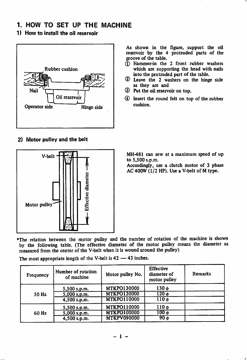
As shown in the figure,
reservoir by
grooveofthe
^
Hammer-in
which are
into
®
Leave
as
(D
Puttheoil
the
they
table.
protruded
the 2
are
the4protruded
the 2 front
supporting
washers
and
reservoir
support
partsofthe
rubber
the
head
partofthe table.
on the
with
hinge
ontop.
the oil
washers
nails
side
0 Insert the round felt on top of the rubber
cushion.
MH-481 can sew at a
to
5,500
Accordingly, use a clutch
AC 400W
s.p.m.
(1/2
maximum
HP). Use a V-beltofM
speedofup
motorof3 phase
type.
1
♦The
relation
by the
measured from the
The most appropriate length of the V-beltis42 — 43 inches.
Frequency
following
50
Hz
60
Hz
between
the motor
table.
(The
centerofthe
Numberofrotation
of
machine
5,500
5.000
4,500
5,500
5,000
4,500
effective
V-belt whenitis
s.p.m.
s.p.m.
s.p.m.
s.p.m.
s.p.m.
s.p.m.
pulley
and the number of rotation of the
diameter
Motor
MTKPOl
MTKP0120000
MTKPOl
MTKPOl
MTKPOl
MTKPV090000
pulley
- 1 -
of the motor
wound
No.
30000
10000
10000
00000
around
Effective
diameter
motor
the
130
120
1100
1100
100
90
pulley
pulley)
of
pulley
4>
4)
0
0
machineisshown
means
the
Remarks
diameter
as
Page 4
2.
HOW
TO
OPERATE
THE
MACHINE
1) Cautions on operation
(I) Do not operate the machinewithout fillingup the oil reservoir with sufficient oil.
(D The direction of the rotation of the machine is toward the operator. Do
in
the
reverse
direction.
not
run the machine
(D The maximum rotational speed of the machine is up to 5,500 s.p.m. but for the first month
drop
this
speedtoabout
After
that,
kindofsewing materialorsewing
2)
Lubrication
run
the
4,500
machine
s.p.m.
with
thread
appropriate
and
capabilityofthe
speed
dependingonthe
operator.
natureofwork,
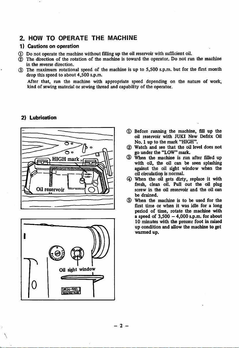
(D Before running the machine, fill up the
oil
reservoir
with
JUKI
New
Defiix
Oil
No. 1 up to the mark "HIGH".
HIGH
(D Watch and see
go
under
<D
When
the
with
oil,
the
"LOW"
machine
the
that
the oil level does
mark.
is run after
oil
can
be seen splashing
filled
not
up
against the oil sight window when the
oil
circulationisnormal.
(4)
When
the oil
gets
dirty,
replace
fresh, clean oil. Pull
screwinthe
be
drained.
oil
reservoir
out
and
the
it with
oil plug
the
oil
can
(D When the machine is to be used for the
first
time
periodoftime,
or whenitwas idle
a speed of 3,500 -
10 minutes
up condition
warmed
with
and
up.
rotate
4,000
the
allow
presser
foralong
the
machine
s.p.m. for about
foot
the
in raised
machine to
with
get
Oil sight
TfrwTW^i
wmdow
I
- 2 -
Page 5
Oil
amount
adjusting pin
Indicating
Needle
Oil
adjusting
^~J^\Arm
_J
Counterweight
•Indicating
point
Crank
Oilisminimum
Crank
III/.11
IS
maximum/
bar
crank
Grooveofeccentric
pin\
|
shaft
Oil adjusting
pin
pin
{
I
pin
screw
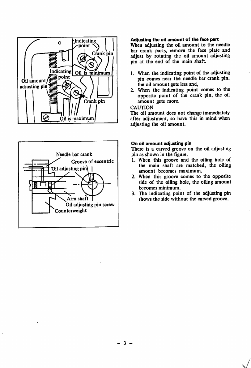
Adjusting
the
oil
amountofthe
face
part
When adjusting the oil amount to the needle
bar crank parts, remove the face plate and
adjust by rotating the oil amount adjusting
pin at the end of the main shaft.
1. When the indicating point of the adjusting
pin comes near the needle bar crank pin,
the oil
amount
gets less and,
2. When the indicating point comes to the
opposite point of the crank pin, the oil
amount
CAUTION
The oil
after adjustment, so have this in mind when
adjusting
On
There is a carved groove on the oil adjusting
pin as shown in the flgure.
1. When this groove and the oiling hole of
2. When this groove comes to the opposite
3. The indicating point of the adjusting pin
gets
more.
amount
does
the
oil
amount.
oil
amount
adjusting
the main
amount
side
becomes
shows
shaft
becomes
of
the oiling hole, the oiling
minimum.
the
side
without
not
change immediately
pin
are
matched,
maximum.
the
carved groove.
the oiling
amount
- 3 -
Page 6
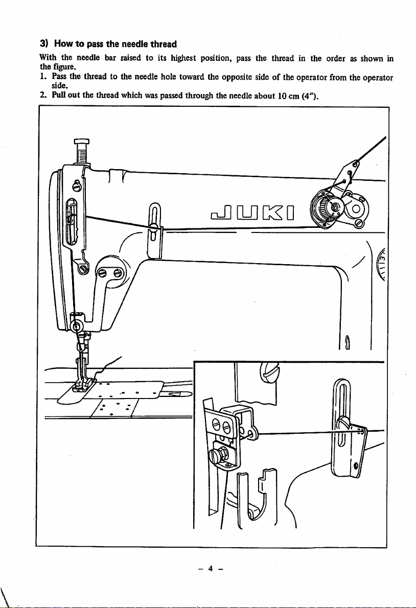
3) Howtopass the needle thread
With the needle bar raised to its highest position, pass the thread in the order as shown in
the figure.
1.
Pass
the
thread
to the
needle
hole
toward
the
side.
opposite
2. Pull out the thread which was passedthrough the needle about 10cm (4").
side
of theoperator
from
the
operator
T~rr
cJ]lU]CSD
- 4 -
Page 7

4) Howtopass
Pas9>the
looper
1. Pass the looper thread through
the
thread
shownin the Fig.®.
2. If the plate springofthe sketch is pulled toward front, A will rise. There are 4 thread holes
of®
These
Holes (1) (2) are for threads with specially strong stretchy quality such as woolie nylon etc. or
when the stitch length are over 3 mm(1/8").
Holes (D (4)are for cotton thread or less stretchy quality".
the
looper thread
thread
as shown in the flgure.
is strongly twisted or when
shouldbe used
the
separately
looper thread guide plate, as shown in the figure. When
the
stitch
according
length is large, pass
the
looper
to the nature of the looper thread.
thread
oJlQilKU
as
O)
^
O®
3. In passing the
a
tweezerinthe
passing, pull it
tipofthe
looper.
threadtothe
accessory
out
box
S cm (2") from the
loopor, use
and
after
- 5 -
Page 8

5)
The
thread
tension
Adjusting
the
needle
Rotatetorighttomake
tension
stronger
6) Presser
Adjusting
Adjusting
the
the
foot
pressing
and
pressing
thread
the'OTJ
I
feed
pressure
pressure
tension
dog
Adjusting
On
presser
the
foot
looper
thread
Rotate
to right to make the
tension
stronger
CD
hand
lifter
tension
O
If the pressure adjusting screw is turned to
right, the pressure becomes stronger
it's
turned to left, the pressure becomes
and
weaker. The standard pressure is 5 kg.
Presser
foot
hand
lifter
To stop the presser foot at the lifted position,
if
rotate
the
presser
foot
right or left.
To lower the presser foot, manipulate the
knee lifter once and the presser
returntoits
- 6 -
original
hand
position.
lifter
either
foot
to
will
Page 9

On
chain-off
thread
7) On stitch length
8)
HowtoInstall
presser
the
Stopper
needle
Feed
direction
Irrespectiveofhigh speed or low speed sew
ing, a small chain-off thread presserisbuilt-in
in
the
thread
MH-481
comes
modelsothat
out
easily.
the
Conventional
chain-off
presser
foot for general lock stitch can be used if no
question is asked for chain-offthread.
Adjusting the stitch length
The
stitch
length
of
this
adjusted by
on
topofthe
rotating
feed lever.
model can be
the
feed adjusting dial
The figures on the graduation scale is shown
in
millimeter
1.
Rotate
right
2. Match
coming
(mm).
the
feed adjusting dial
or
left
and
the
wanted
out
from the frame.
figure
with
either
the
to
pin
* The maximum stitch length is 4 mm(5/32").
3.Ifthe
4. If the position
leverispushed,itbecomes
sewing with the standard pitchof2mm
(5/64").
raised ,
sewing
the
pitch
becomes
of
the
of
small.
lever
the
reverse
stopper
reverse
is
5. If the position of the lever stopper is
raised up further (loosen the nut and pull
the
stopper
up)
and
the
lever is pushed,
it is possible to sew with normal sewing
with
small
stitch
length.
Take advantageofthis feature for bar-
tacking at the start of sewing or end of
sewing.
\
(J)
Directionofthe
hole
needle
The designated needle is TV x 7,
For stabilizing the reverse sewing, do
make
the
in the
- 7 -
directionofthe
figure©.
#9~#21.
not
needleasshown
Page 10

9)
Howtoinstall
the
silicon
Knob
oil
screw
lubricant
unit
MODEL MH-481 is provided
with
SILICON
OIL LUBRICATING UNIT for sewing with
syntheticormixed
As
showninthe
the
set
screw
unit installing
as
showninthe
Fill up
the
knob
screw is
into
the
After
felt.
that
tighten the
of
stud
figure
tank
loosened,
synthetic
figure, loosen
the
silicon
and
install the felt case
left.
with
silicon oil
silicon oil will
knob
thread.
and
oil
andifthe
screw fully and
when the punch markoftHe knob screw has
returned
amount
When
work
hour,besure
tightened
and
smoothly.
about
half~one
is considered to be
the
day's
is to be
the
workisdoneor-when
stopped
to leave
and
the
silicon
next
operation
appropriate.
for
the
knob
oil will
can be
rotation,
more
screw
not
than
remove
lubricant
seep
the
one.
firmly
leak
resumed
oil
the
out
When silicon oil lubricant unit
be sure to stop it as shown in the figure.
- 8 -
isjiot
in use,
Page 11

3.
ADJUSTING
1) Adjusting
the
THE
presser
MACHINE
foot
and the feed dog
Howtoinstall
A
the
type
Presser
feed
bar
dog
clamp
Standard
screw
B
type
Adjusting
When
presser bar is to be
exchangeofpresser
the
the
heightofthe
height or
the
changed
foot:
presser
bar
directionofthe
duetothe
1. Remove the rubber plug of the face plate.
2. From this hole, adjust by loosening the
presser
bar
screw.
clamping screw.
®
Forked
arm
the
screw
3. After the adjustment, securely tighten
set
If the screw d) of figure is loosened, the slant of the feed dog can be adjusted either to A type
or B type. The
this
amountbyscrew
maximum
(T).
protruding amount of the feed dog is 0.8 mm(l/32"). Adjust to
Matching
When the needle point has dropped to 3mm
(1/8")bottom
adjust the positionofthe feed dog by the
the
needle and
the
surfaceofthe
the
feed
dog
throat
plate,
screw of flgure so that the feed dog sinks
just below the lower surfaceofthe
plate.
Screw
-
- 9 -
throat
Page 12

Adjusting
lever
The reversing spring
the
pressing pressure of
of
the
feed
the feed lever is
strengthened somewhat so that at high speed
sewing, no
matter
what
kindofstitches
are
to be formed, the lever returns positively to
the original position.
When the stitching pitch is small or when the
machine is to be run by lowering the r.p.m.,
the pressing pressureofthe feed lever can be
lessened by loosening the adjusting nut (D of
the accompanying figure.
2)
On
needle
bar
and
needle
Adjusting
lever
The reversing spring
the
pressing pressureofthe
of
the feed lever is
feed
strengthened somewhat so that at high speed
sewing, no
matter
what
kindofstitches
are
to be formed, the lever returns positively to
the
original position.
When the stitching pitch is small or when the
machine is to be run by lowering the r.p.m.,
the pressing pressureofthe feed lever can be
lessenedby looseningthe adjusting nut ® of
the accompan)dng figure.
2)
On
needle
bar
and
needle
Adjusting
the
heightofthe
needle
bar
When an Organ needle (TV x 7) is used, set
the
(27
Schmetz
heightofthe
needle bar has reached to lower dead point,
the
left
side
with
the
lower bushing. (See Ggure)
Also, when
is
used,
match
line comes
above.
(At
tween the needle
the
throat
-
10
-
needle bar so
carved
line
bottom
the
Schmetz
it sothatthe
to
this
plate becomes
(No.l
surface
of
needle (5463-35
ri^t
the position as mentioned
condition,
point
and
10.0
the
upper
that
when
mark)
matches
the
needle
side
carved
distance be
surface
mm(25/64").
the
bar
etc.)
of
Page 13

Punched
mark
Adjusting
screw
1
Remove
2
Rotate
3 The heads of the plated adjusting screw®,
flat
in
2 screws, flat
4 If
screw ® is brought to right side, the
dimensionofB
5 Adjustment is made dependingon the size
numberofthe
adjustedto#11
6 The adjustment should be made so that
the
rubber
the
top
screw, clainp screw will
that
order,
the
punched
cap.
hand
wheel
so at first, loosen
top
and
markofthe
becomes
needle
needle.
with
the
hand.
clamp screw.
bigger.
but
normallyitis
appear
the
adjusting
the looper goes as near the needle side
as
possible
the position by tightening the flat top
screw, securely tighten the clamp screw.
and returns.Then, after setting
Matching
When
looper comes to
adjustmentismadebyloosening
of
Screwofgear
Scooping
When
distance
the No. 2 carved line of the needle bar is matched with the lower edge of the needle bar lower
bushing,
returning
ship
Clearance
The
beasnarrowaspossible.
ofthe
1 .S
amountofthe
the
blade
between
adjust
amount
needle
mm'
looper
point of the
the
blade
so that the
of the
looper
hole
and
looper
point
has
upper
of the
pointand the
blade
comestoapproximately
the
thread
hole
of the
Adjusting
reached
endof the
looper
looper
3.2
mm
the
returning
betweenthe looperandthe needle j i. u
clearance
between
the
After
looper
adjusting
andthe
the
needle
needle
when
guard,
the
looper
the
needle isatthe
extreme
the gear.
the
center
of the
needle
holeis1.5mm{l/16).When
comestothe
3.2mm(l/8")
becomesasshown
amount
the
looper
re-confirm
this
center
and
inthe
scoops
condition.
needle,
the
up the
lowest
the
needle.
relative
point,
the
screw
standard
relation
right position. This
of the
figure.
thread
should
the
The
-
11
-
Page 14

4) On thread spreader
\
1
No.4mark
Extreme
right
It
end
Thread
reverse sewing
importanttoobtain
skip-stitching in case of normal feed sewing.
The timing of thread spreader against
needle
As shown in the figure, when the No. 4 mark
of the needle bar appears from the bottom of
the needle bar lower bushing, set the thread
spreader with the thread spreader cam set
screw, as
thread spreader comes to extreme right end.
spreader
shown
Screwofthread
spreader
cam
is necessary in case
andatthe
same time it is verj'
stable
stitches
in the figure, so
without
that
the
the
of
Positionofthe
When
the
bushing, adjust
thread
No.3carved
the
thread
spreader
latch
lineofthe
needle
barismatchedtothe
spreader as shown in the figure.
bottomofthe
needle
bar
lower
(D The right and left direction should be such that the inside surface of the thread spreader
should
match
with
the
center
of
the
@
Adjust
sothat thefrontandback
needle.
dimensionAshould
be2
mm(5/64")
withthe
screw
CD.
(3) The height should be adjusted so that the clearance between the bottom surface of the
thread
spreader
Thread
and
spreader
Inside
Needle
the
line
upper
surfaceofthe
Thread
spreader
looper
to be 0.2
Methodofthread
mm(l/100")
Looper
spreader
with
the screw (2).
X When the thread spreader latch returns,
the
tipofthe
thread
spreader
latch
is
positively pasping the looper thread and
one side of the needle thread loop until
the needle point enters the triangle of the
Triangle
Looper
thread.
After the needle point has entered the
triangle,
thread.
Above are the
for
form
both
correct
the
normal
looper
thread
and
stitches.
should
spreader
reverse
release
adjustments
stitches
the
to
-
12
-
Page 15

5) Needle guard and loop guide
Set
screw
needle guard cam
of
The
timingofthe
needle
guard
The timingofthe needle guard is determined
by matching the first screw of the figure
with the flat
partofthe shaft.
L.
Looper guide
Positionofthe
When
the
adjust so
looper
that
needle
guard
scoopsupthe
the
needle
point
lightly touches
needle
thread,
the needle guard. Set the height as high as
possible to
loop. Loosen set screws
adjustment.
Positionofthe
about
looper
cover
guide
the
needle
(T)
and © for this
thread
The looper guide should be installed as near
the looper as possible so
that
it will
not
touch the looper. Adjust it so that the
dimensionofA
(1/100"—1/64"),
0.5—1.0
Dimension
loosening
willbeabout
mm
(1/64"—3/64").
of
A
screw
(J)andof B
and
should
of
0.2
B to be
be
adjusted
loosen
—0.5
screw
mm
about
®.
by
-
13
-
Page 16

6) On
7) On
looper
the
thread
position of
cam
No.3mark
f
Matching
the
take-up
hole
Wire
thread
As shown in the figure, when the No. 3
carved
lineofthe
bottom
bushing, makeitso
seen through the hole
of
cam can be adjusted by loosening the screw B
and
the
After
surface
the cam.
after
the position is determined tighten
screw
securely.
all adjustments are completed, verify
needle
bar
of
the
that
The
timingofthe looper thread
comestothe
needle
the wire can be
of
the matching hole
the following:
1. Verify
that
off
from the
looper
thread
completely
loopef thread.
when the looper
protruded
cam,
entered
end
the
needle
the
triangleofthe
thread
tension lever
When the needle bar is at the lowest point,
if the needle thread is pulled in by hauling
motion by the take-up thread tension lever,
the needle thread loop becomes big at the
scooping
In caseofnormal fine thread, lower the
timeofthe
needle
thread.
needle to the lowest dead point.
bar
point
lower
came
of
the
has
8) On
J/-
the
frame thread eyelet
The thread tightening
changes
according
to
the positions of the frame thread eyelet.
When the frame thread eyelet is lowered,
the tightening of the looper thread becomes
weaker and if it's raised up, the tightening
becomes stronger.
-
14
-
Page 17

4.
MAINTENANCE
OF
THE
MACHINE
To maintain
the
machine in
constant
smooth
running
condition,
be sure to do as follows:
1) Give the machine an overall inspection daily and verify its running condition.
* Verify if the oil is circulating smoothly by watching through the oil sight window.
* If a different operator is running the machine daily,, be sure to have him contact an
expert
maintenance crew
for
guidance.
2) Inspect the following parts at least once a week:
* Throat plate, sliding plate and remove the cam cover and by usinga brush dust off the
dirt
from the groove of
*
Tilt
the machine toward the opposite side and,
the
feed
dog.
(1) Remove the thread hards stuck to the oil pump netting and remove the rubbish inside
the
oil
(2) When the oil becomes dirty and blackish, pull
(3) Verify
(4)
5.
No.
1
reservoir.
oil
with
new,
fresh
JUKI
Defrix
that
the
Wipe
away the black steel powder sticking to the magnet at the bottom of the oil
reservoir.
oil level is always above
MALFUNCTIONS
Malfunctions
Thread
breakage 2.
1. Qualityofthread
Threadisthick
to
Thread
3.
heatofneedle.
4.
Thread
strong.
5.
The
needle,
Oil No. 1.
&
CORRECTIVE
Causes
needle.
breakage due
tensionistoo
thread
path
looper,
the
is bad.
compared
of
throat
out
the oil plug and exchange the dirty
"LOW"
mark.
MEASURES
Corrective
Measures
(D Usea better quality thread
(D
Change
the needleor
threadtoproper
<D
to
This occurs on synthetic
thread.
Use
silicon
the
oil
r.p.m.
Lower
(D Weakenthe thread tension.
(D Sharpen with oil whet
stoneorby
bufflng.
size.
lubricant.
plate, needle guard.
looper guide and all
other
thread
paths
are
(D Activate the thread take-
of
up
tension
(D Verify the scooping
amountoflooper.
lever.
2
Skip-stitch
bruised.
6. Due to twice passing
thread.
1. Skip-stitchingofneedle
thread.
(D Verify the clearance
f f
between
needle.
the
looper
and
(D Verify the timing of the
looper
2
stitches
*(This
does
thread)
collapse
occurs
not
scoop needle
when
0 Depending on the thread.
looper
& needle.
activate
the
thread
take-up tension lever.
Ref.
Page
7
8
6
14
11
11
11
14
-
15
-
Page 18

No.
Malfunctions
Causes
Corrective
Measures
Ref.
Skip-stitch
W
2.
Looper
thread
skip-stitches.
One
stitch
collapes
Needles.
occurs
drops
Needle
'Looper
when
the
into
the
f
linking
threadistoo
side.)
Looper
(This
needle
triangleofthread.)
Inadequate
loop. (This occurs when
the
needle
muchonleft
Besides
above
(In caseofsynthetic thread.)
Verify
the
installationofthe
Verify the timingofthe
needle guard.
Refer to the passing
@
the
thread.
®
Verify
(2) Verify
(3)
above
the
looper
thread
Adjustthe positionof
the
thread
hook
0 Make the tensionofthe
looper
thread
0 Referto
thread.
0 Refer to 1. 3. of skipping
of
of
needle
(D Verifythe timing of the
thread
spreader
positionofhookofthe
looper
0 Drop the sewingspeed
0 Usesilicon oil lubricant.
Use
needle
thread.
correct
(p&
timingofthe
cam.
spreader
stronger.
passing
of the
thread.
and
for
synthetic
needle
of
Q).
7
13
4,5
14
12
6
4,5
12
Inadequate
tightening
of
thread
(In caseofmixed synthetic
thread.)
When
the
needle
tensionisweak.
When
the
bobbin
thread
thread
tension is strong.
Insufflcient palling out
of
looper thread cam.
The
threadistoo
against
the
thick
needle.
Depending on the posi
tionofintermediate
thread
guide.
-
16
0 Make the scooping
amountoflooper
@
Drop
the
sewing
0 Use silicon oil lubricant
0
Tighten
the
needle
nut.
the
looper
nut.
the thread
thread
the
needle.
the
positionofthe 14
0
0
0
tension
Loosen
tension
Change
to
looper
Change
Lower
frame thread eyelet.
-
greater
speed
thread
thread
passing
cam.
11
1
6
6
14
7
Page 19

No.
Malfunctions
Needle
breakage
Puckering
Causes
6.
Positionofthe
thread
take-up thread tension
lever.
7.
The
throat
plate
1. Needle
2. Inspect the timing
may
be curved.
of
the feed dog with the
needle.
3. Inspect
4. Needle
5.
6.
1.
the
of
presser
installation
foot.
guard
When
the
needle
strong.
Thicknessofneedle.
Tensionofthreadistoo
strong.
tensionofthe
threadistoo
2. Timing of the looper
cam.
3.
Processed
thread
condition
path.
4. When pressing pressure
of presser
strong.
footistoo
Corrective
Raise up
of
0
the
Use
throat
lever.
large
plate
Measures
the
needle
® Changethe needle.
Is the timing correct ?
(3) Seeifthe
foot,
and
placed in
needle.
holeofpresser
holeofthroat
loop
guide
the
® Verify the timing
positionofneedle guard.
(5)
Make
the
needle
tensionofthe
thread
(D Select the correct size
needletoconformtothe
natureofthe
cloth
and
its
® Sew with weaker tension.
(Especially,
tensionoflooper
(D Verify if the timing is
of
correct.
(3) Polish
with
thick
@
Loosen
screw
the
lapping agent on
thread
the
position
hole
plate
center
weaker.
sewing
thickness.
lower
thread
#8
adjusting
plate
are
of
and
the
thread)
path
Ref.
Page
14
10,
7
11
13
6
7
6
14
(Please
note)
* Due to improvements on the mechanism of the machine, the method
of operation and some
without
previous
notice.
partofthe
specification may have to be changed
-
17
-
Page 20

flKYO
JUKI
lOKrO
Head
Office&Plant,
Business
Cable
Office:
Address:
JUKI
23.
JUKI
mDUSIRIAl
2-1,
8-cHome,
Kabuki-cho.
TOKYOITelex:
Kokuryo-cho.
Shinjuku
CO..LTO.
Chofu
ku.
Tokyo,
232-2301,
shi.
Japan
-1BH481BEB
Tokyo.
Japan
Printedin Japan(T)
 Loading...