

Page 1

LU-2828-7, 2828-6
INSTRUCTION MANUAL
Page 2

CONTENTS
1. SPECIFICATIONS ...................................................................................................... 1
2. INSTALLATION .......................................................................................................... 2
2-1. Installation of the sewing machine ................................................................................... 2
2-2. Installing the belt cover and the belt (LU-2828-6) ............................................................ 5
2-3. Adjusting the belt tension (LU-2828-6) ............................................................................. 6
2-4. Installing the synchronizer (LU-2828-6) ............................................................................ 6
2-5. Adjusting the synchronizer (LU-2828-6) ........................................................................... 7
2-6. Installing the oil shield ....................................................................................................... 8
2-7. Pneumatic components ..................................................................................................... 8
2-8. Wiring the machine head (LU-2828-6) ............................................................................. 10
2-9. Installing the thread stand ............................................................................................... 14
2-10. Installing the thread guide pin ....................................................................................... 14
3. PREPARATION OF THE SEWING MACHINE ........................................................ 15
3-1. Lubrication ........................................................................................................................ 15
3-2. Attaching the needle......................................................................................................... 17
3-3. Attaching and removing the bobbin ............................................................................... 17
3-4. Threading the hook .......................................................................................................... 18
3-5. Winding a bobbin .............................................................................................................. 18
3-6. Threading the machine head ........................................................................................... 19
3-7. How to set the model of the machine head (LU-2828-7) ............................................... 20
3-8.
Adjusting the machine head
(LU-2828-7) .......................................................................... 22
4. ADJUSTING THE SEWING MACHINE ................................................................... 24
4-1. Adjusting the stitch length............................................................................................... 24
4-2. Thread tension .................................................................................................................. 25
4-3. Thread take-up spring ...................................................................................................... 26
4-4. Adjusting the pressure of the presser foot .................................................................... 27
4-5. Needle-to-hook relation .................................................................................................... 28
4-6. Adjusting the hook needle guard .................................................................................... 29
4-7. Adjusting the bobbin case opening lever....................................................................... 29
4-8. Adjusting the moving knife, the counter knife and the bobbin thread clamp............. 30
4-9. Adjusting the thread trimming cam timing..................................................................... 32
4-10. Adjusting the condensation stitch ................................................................................ 33
4-11. Adjusting the amount of the alternating vertical movement of the walking foot and
the presser foot ............................................................................................................... 34
5. OPERATION OF THE SEWING MACHINE ............................................................. 34
5-1. Hand lifter .......................................................................................................................... 34
5-2. Resetting the safety clutch .............................................................................................. 34
5-3. Adjusting the automatic presser foot lifter .................................................................... 35
5-4. Fixing the feed adjusting dial .......................................................................................... 36
5-5. Normal-/reverse-feed stitch needle entry points alignment at the time of automatic
reverse feed stitching ..................................................................................................... 37
5-6. Operation switches ........................................................................................................... 38
5-7. Knee switch ....................................................................................................................... 40
5-8. Function setting for the SC-922 (LU-2828-7) .................................................................. 43
6. SEWING SPEED TABLE ......................................................................................... 46
7. TROUBLES IN SEWING AND CORRECTIVE MEASURES ................................... 47
i
Page 3

1. SPECIFICATIONS
No. Item Application
1 Model LU-2828-7 LU-2828-6
2 Model name 1-needle, unison-feed, lockstitch
machine with automatic thread trimmer
(with 2.7-fold vertical axis hook/needle
thread clamp function/direct drive type)
3 Application Medium- to heavy-weight materials, car seat, furniture
4 Sewing speed Max. 3,000 sti/min
"6. SEWING SPEED TABLE" p.46
(See
5 Needle SCHMETZ 134-35 (Nm 125 to Nm 180) (Standard : Nm 140)
6 Applicable thread size for sewing #30 to #5
7 Applicable thread size to be cut #30 to #5
8 Stitch length Max. 9 mm (forward/reverse feed)
9 Stitch length dial 2-pitch dial
10 Presser foot lift Hand lifter : 10 mm
Automatic presser foot lifter : 20 mm
11 Stitch length adjusting
mechanism
12 Reverse stitch adjusting method Air cylinder type (with touch-back switch)
13 Thread take-up Link thread take-up
14 Needle bar stroke 40 mm
By dial
1-needle, unison-feed, lockstitch
machine with automatic thread trimmer
(with 2.7-fold vertical axis hook/needle
thread clamp function/V belt type)
*1
.)
15 Amount of the alternate vertical
movement
16 Hook Full-rotary vertical-axis 2.7-fold hook (Latch type)
17 Feed mechanism Box feed
18 Top and bottom feed actuation
mechanism
19 Thread trimming method Cam-driven scissors type
20 Lubrication Automatic lubrication by oil tank (with oil gauge)
21 Lubricating oil JUKI New Defrix Oil No. 1 (equivalent to ISO standard VG7)
22 Bed size 643 mm × 178 mm
23 Space under the arm 347 mm × 127 mm
24 Hand wheel size Outer diameter : ø123 mm
25 Motor/Control box SC-922B -
26 Machine head weight 62 kg
27 Rated power consumption 180VA
28 Noise
*2
- Equivalent continuous emission sound pressure level (LpA) at the workstation:
A-weighted value of 81.0 dB; (Includes KpA = 2.5 dB); according to ISO
1 mm to 9 mm (Alternate vertical dial adjustment type)
Timing belt
or JUKI MACHINE OIL No. 7
10821- C.6.2 - ISO 11204 GR2 at 3,000 sti/min.
- Sound power level (LWA);
A-weighted value of 85.5 dB; (Includes KWA = 2.5 dB); according to ISO
10821- C.6.2 - ISO 3744 GR2 at 3,000 sti/min.
*1 The speed setting according to the amount of the alternating vertical movement of the walking foot and presser
foot is automatically carried out.
*2 The noise level show in the table is the level generated in the case JUKI's control box (SC-922) is used.
– 1 –
Page 4
2. INSTALLATION
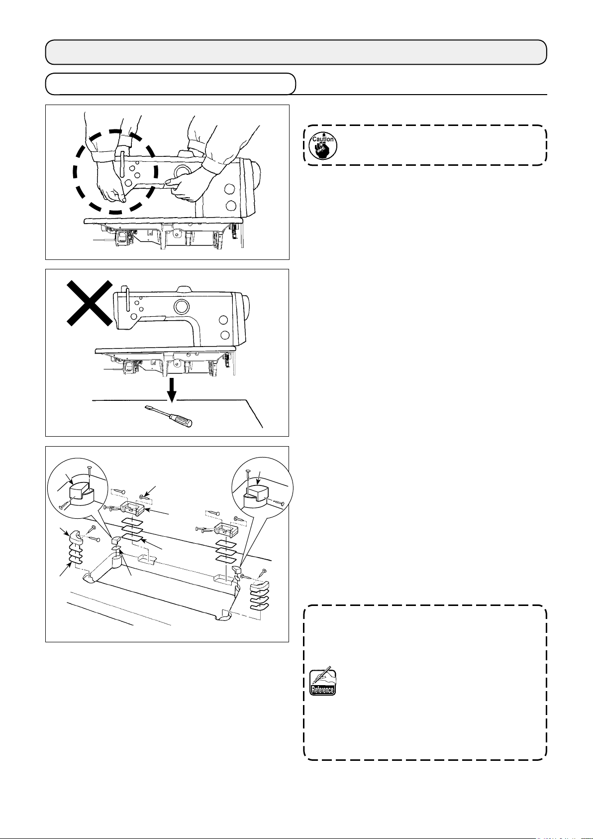
2-1. Installation of the sewing machine
1) Carry the sewing machine with two persons.
Do not hold the pulley and the reverse feed
lever.
2) Do not put protruding articles such as the
screwdriver and the like at the location where
the sewing machine is placed.
❸
❷
Sheet B
Sheet C
❹
❶
Sheet A
❸
3) Attaching the hinge seats and the support rub-
bers of the machine head
Place sheets A and B (standard: three pieces)
and C (standard: one piece) between hinge seat
and machine head support rubbers ❷ and ❸.
❶
Then, x them on the table with nail ❹.
There are two different machine head support
rubbers ❸; i.e., the rubber for the right and that
for the left. Be sure to check the types of the
support rubbers before xing them.
Sheets A and B (eight pieces each) and
sheets C (four pieces) are supplied with the
machine as accessories.
For the sheets A and B, three sheets are
to be used as standard for each mounting
position. For the sheet C, one sheet is to be
used as standard. (The state shown in the
left gure)
The sheets A, B and C are used for adjusting the height of the top surface of the bed.
Use one more sheet to increase the height,
or use only one sheet to decrease it.
– 2 –
Page 5
Operator’s side
❺
Align
Table
Align
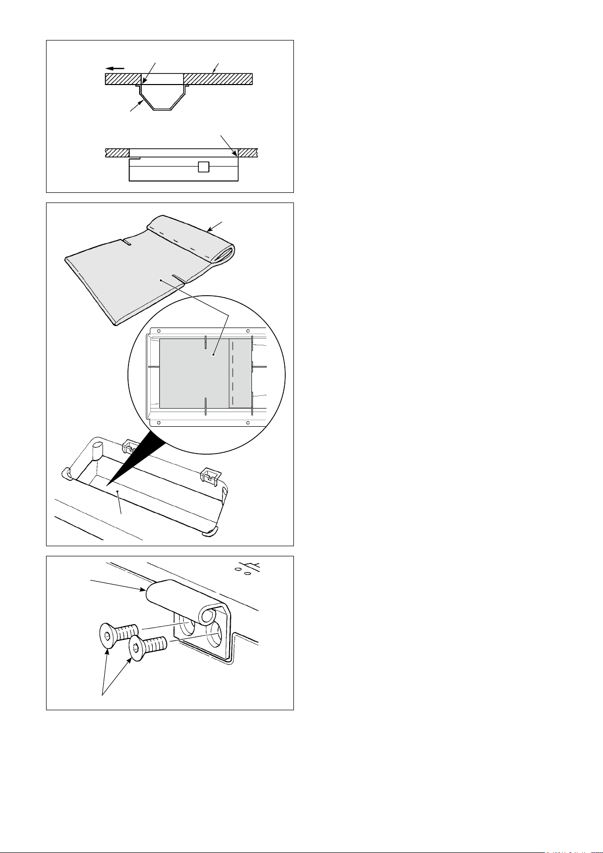
4) Attaching the oil pan
Fix the oil pan ❺ supplied with the machine on
the table by tightening ten wood screws.
Top surface
Multi-layered part
❻
5) Attach a lter ❻ to the oil pan ❺ as shown in
the gure.
Install lter ❻ so that its multi-layered part is
brought to the right side as observed from you.
❼
❺
6) Install hinge ❼ on the bed with screw ❽.
Engage the hinge with the rubber hinge of the
table. Then, place the machine head on the
machine head support rubber.
❽
– 3 –
Page 6
❾
❺
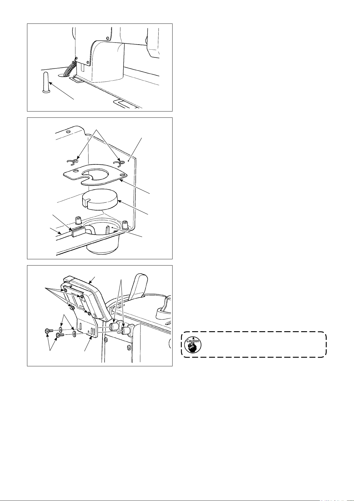
7) Securely attach head support rod ❾ until its rib
is closely pressed against the table.
8) Put reux pipe in the oil reservoir A of oil
pan ❺. Secure the pipe in groove .
9) Fix lter and lter clamp with tting .
A
10) Mount spacers supplied with the machine
head on the frame.
11) Install bracket on CP panel with screws
supplied with the panel.
12) Install bracket on spacer with screws
supplied with the machine head and washers
supplied with the panel.
Do not use the screws supplied the panel
instead of screws supplied with the machine head.
– 4 –
Page 7
2-2. Installing the belt cover and the belt (LU-2828-6)
WARNING :
To protect against possible personal injury due to abrupt start of the machine, be sure to start the
following work after turning the power off and ascertaining that the motor is at rest.
(Installation procedure)
❶
❺
V-belt
1) Remove belt cover A ❶.
2) Pass the 14P connector which puts cables
together and the air tube through the slotted
hole in the table.
3) Put the V-belt on the sewing machine pulley.
4) Adjust the belt tension.
5) Pass synchronizer support shaft ❷ and washer
through mounting hole in belt cover A ❶ and
❸
x the synchronizer support shaft with washer
and nut ❹.
❸
6) Mount belt cover A ❶.
7) Install belt cover B ❺ on the table.
Be sure to use the sewing machine with
safety devices ❶ and ❺ installed.
Slotted hole in
the table
❶
❸
❷
❸
❶
❹
– 5 –
Page 8
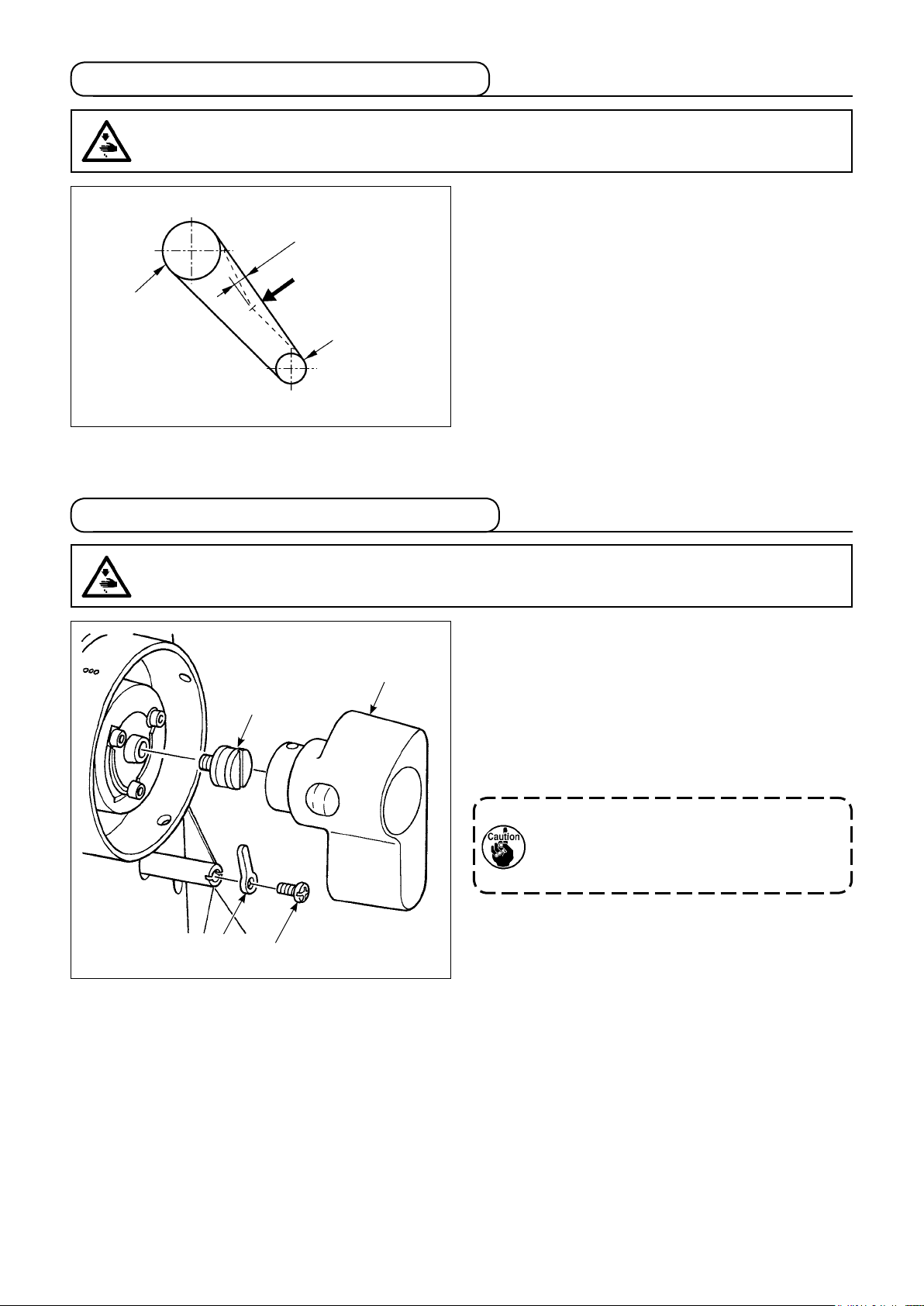
2-3. Adjusting the belt tension (LU-2828-6)
WARNING :
To protect against possible personal injury due to abrupt start of the machine, be sure to start the
following work after turning the power off and ascertaining that the motor is at rest.
15mm
9.8N
Handwheel
Motor pulley
2-4. Installing the synchronizer (LU-2828-6)
Adjust the belt tension with the height of the motor
so that the belt sags 15 mm when the center of V
belt is applied with a 9.8 N load.
WARNING :
To protect against possible personal injury due to abrupt start of the machine, be sure to start the
following work after turning the power off and ascertaining that the motor is at rest.
(Installation procedure)
1) Fix synchronizer ange ❶ on the end of the
Synchronizer
❶
main shaft.
2) Fix the synchronizer on synchronizer ange ❶.
3) Fix synchronizer support plate ❷ with setscrew
so as to prevent the synchronizer from
❸
rotating.
Be sure to remove the connector for the
sewing machine for the sake of safety
before checking the upper and lower
positions of the synchronizer.
❷
❸
– 6 –
Page 9
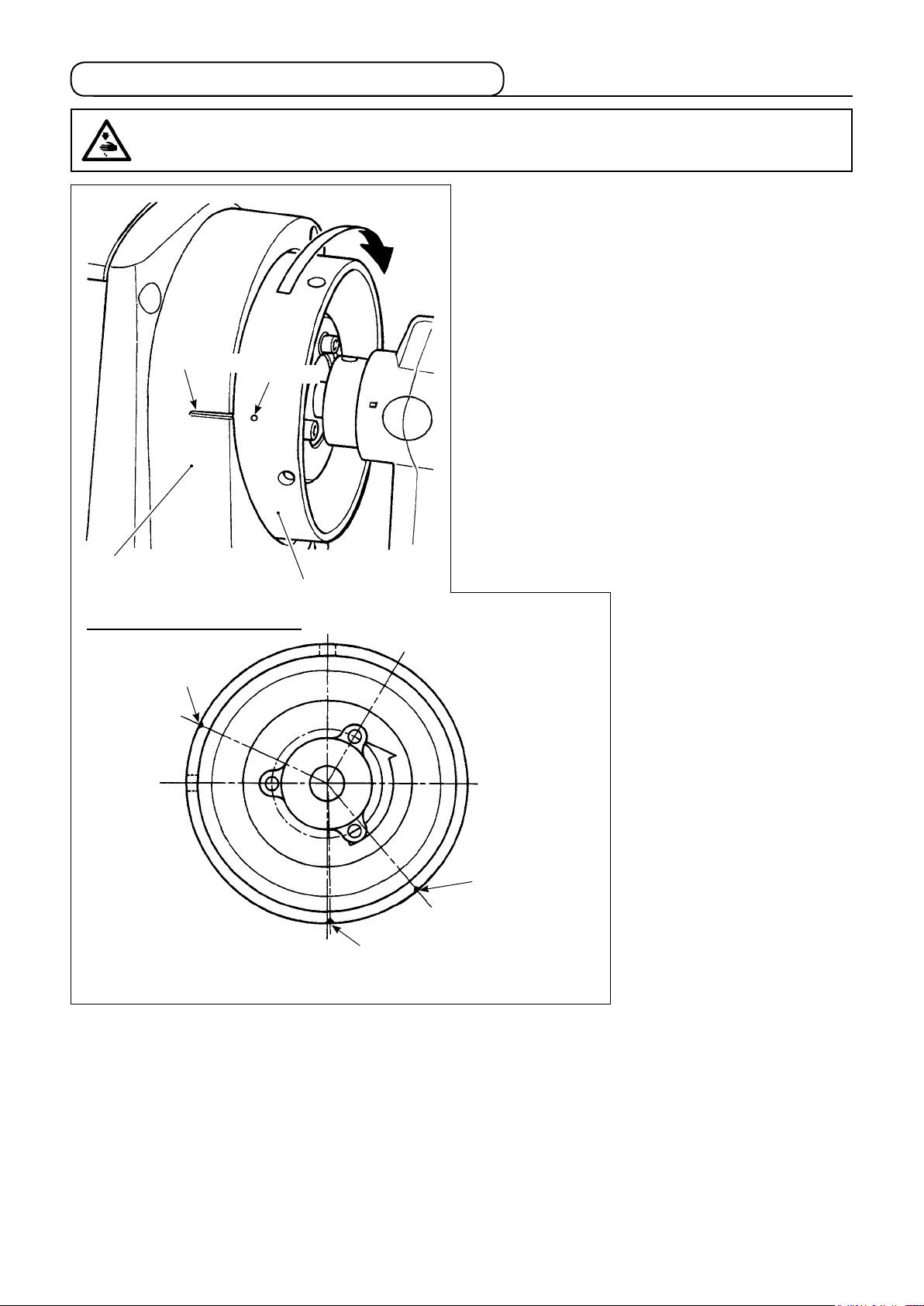
2-5. Adjusting the synchronizer (LU-2828-6)
WARNING :
To protect against possible personal injury due to abrupt start of the machine, be sure to start the
following work after turning the power off and ascertaining that the motor is at rest.
C
Marker line
Marker dot
Adjust the upper stop position (needle-up stop posi-
tion) so that the marker line on belt cover A ❷ aligns
with the marker dot (one) on handwheel ❶(70 °po-
sition).
Adjust the lower stop position (needle-down stop
position) so that the needle bar stops at the position
where the needle bar goes up from the lower dead
point (180 °) by approximately 13 mm (120 °posi-
tion). (The position which is reached by turning the
handwheel from the lower end of the needle bar in
the reverse direction of rotation of the main shaft (di-
rection C))
❷
Marker dot on the handwheel
Upper stop position
(one marker dot)
70 °
❶
Thread trimming
cam alignment
(two marker dots)
275 °
Opener timing adjustment
(three marker dots)
314 °
– 7 –
Page 10
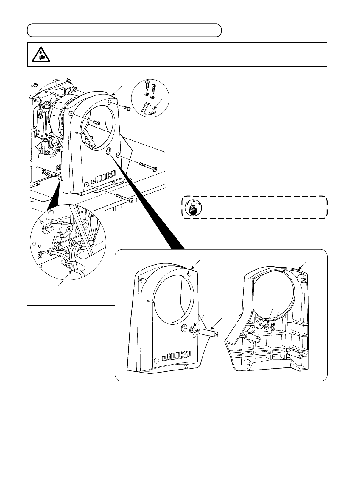
2-6. Installing the oil shield
WARNING :
To protect against possible personal injury due to abrupt start of the machine, be sure to start the
following work after turning the power off and ascertaining that the motor is at rest.
❶
❷
2-7. Pneumatic components
WARNING :
To protect against possible personal injury due to abrupt start of the machine, be sure to start the
following work after turning the power off and ascertaining that the motor is at rest.
❺
❷
❸
❼
❻
❷
❾
❽
Install oil shield ❶, supplied with the unit, on the
frame with screws ❷.
(1) Installing the regulator
1) Install regulator (asm.) ❶ on mounting plate
with screw ❷, spring washer ❸ and nut ❹
❺
which are supplied with the unit.
2) Install couplings ❻ and ❼ on regulator ❶.
3) Install mounting plate ❺ on the underside of the
table.
4) Connect ø6 air tube ❽ and ø4 air tube ❾ com-
ing from the sewing machine to coupling ❻.
❶
Decrease Increase
❹
❶
A
❷
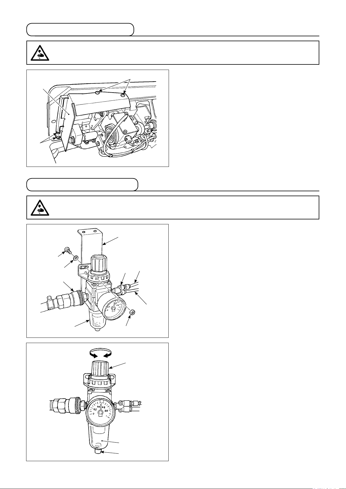
(2) Adjusting the air pressure
1) The operating air pressure is 0.5 to 0.55 MPa.
Adjust the air pressure using air pressure
regulating knob ❶ of the lter regulator.
2) In the case uid accumulation is observed in A
section of the lter regulator, turn drain cock ❷
to drain the uid.
– 8 –
Page 11
❸
(3) Installing the solenoid valve mounting
plate (LU-2828-6)
Install solenoid valve mounting plate asm. ❶ to
the undersurface of the table with screw ❷ and
washer ❸ supplied with the unit.
❷
❶
8 air tube
ø
Solenoid
valve
cable
6 air tube
ø
A
B
❷
❺
❸
❹
❷
❶
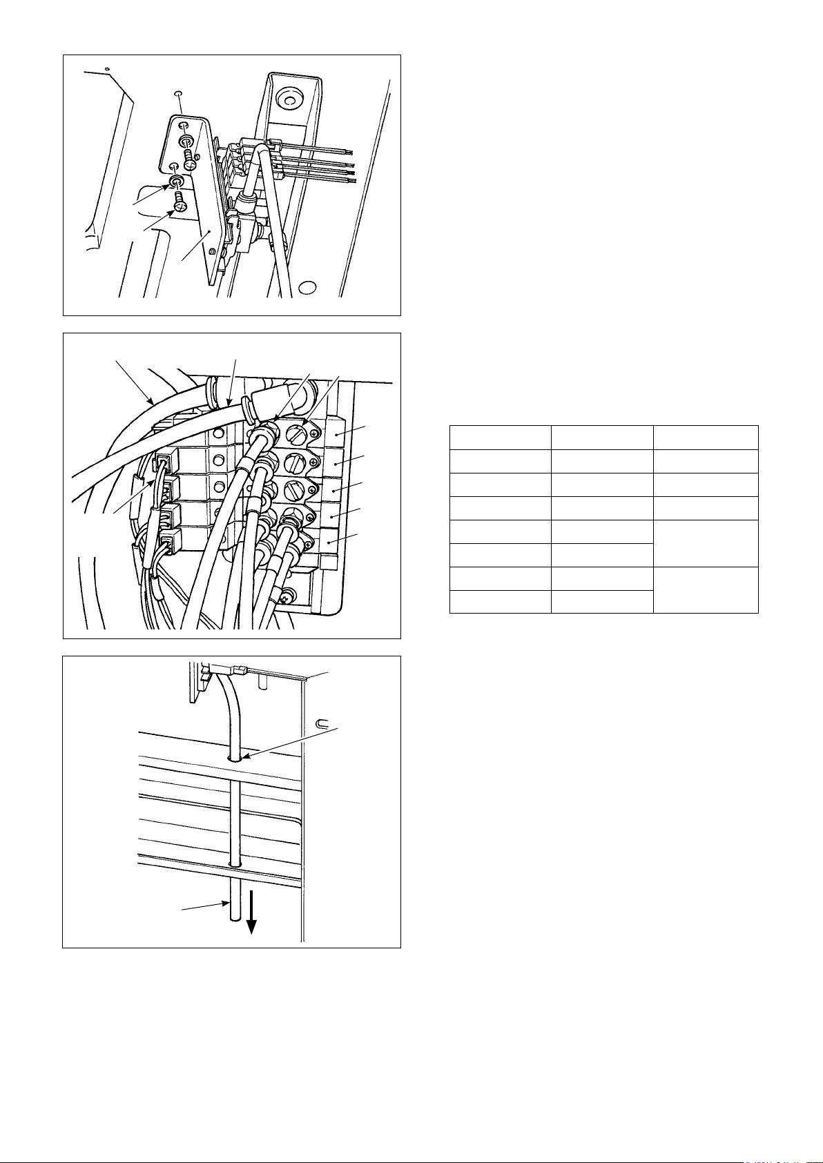
(4) Connecting the air tube and the solenoid
valve cable (LU-2828-6)
Connect the air tubes and the solenoid valve
cable to the locations shown below.
Solenoid valve Tube number Cable number
❶
❷
❸
❹- A
❹- B
❺- A
❺- B
4 CN151
8 CN152
6 CN153
10
CN154
9
2
CN155
1
(5) Exhaust tube
Pass ø8 exhaust air tube ❶ through hole ❷ in
the table stand and other relevant hole. Then,
route the air tube downward. If the humidity is
high, water may come out of the air tube.
❶
– 9 –
Page 12
2-8. Wiring the machine head (LU-2828-6)
WARNING :
Junction cord preparation and wiring to the control box must be carried out by an electrical engineer
without exceptions. Be sure to turn off the power to the sewing machine and wait for ve minutes before
starting the wiring work.
If the pin numbers of the connectors are not correctly connected, errors and breakage of parts and control box can result. Carefully connect the machine-head connectors and the control-box connectors.
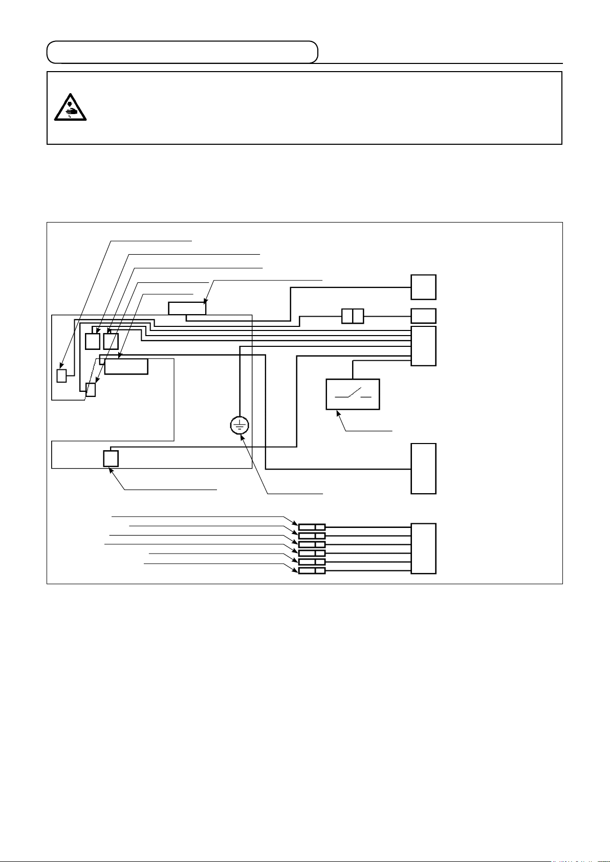
(1) Wiring diagram
Details of the connectors wired to the machine head are as described below.
Refer to
out of the pins.
"(2) Details of connectors"
Thread clamp solenoid
Tension release solenoid (upper side)
Tension release solenoid (lower side)
Reverse feed switch
6-gang switch
Alternate up/down limit switch
on the next page for details of connectors ① to ⑤,
-1: CN37A / 2P connector
⑤
Thread clamp solenoid junction cord
-1
and lay-
⑤
: CN158 / 4P connector
①
Alternate up/down limit switch
(lower side)
Alternate up/down limit switch
(upper side)
: CN37 / 2P connector
⑤
Thread clamp solenoid
: CN36 / 14P connector
②
Tension release solenoid (lower side)
Tension release solenoid (upper side)
Thread trimming solenoid
Reverse feed switch
FG (earth cord)
Knee switch
Thread trimming solenoid
Presser bar lifting cylinder solenoid valve: CN151
Reverse feed cylinder solenoid valve: CN152
Alternate up/down cylinder solenoid valve: CN153
Condensation stitch cylinder solenoid valve: CN154
2-pitch cylinder solenoid valve: CN155
2.5-pitch cylinder solenoid valve: CN156
FG (earth cord)
Knee switch
: CN144 / 16P connector
③
6-gang switch
: CN102 / 12P connector
④
Solenoid valve
– 10 –
Page 13
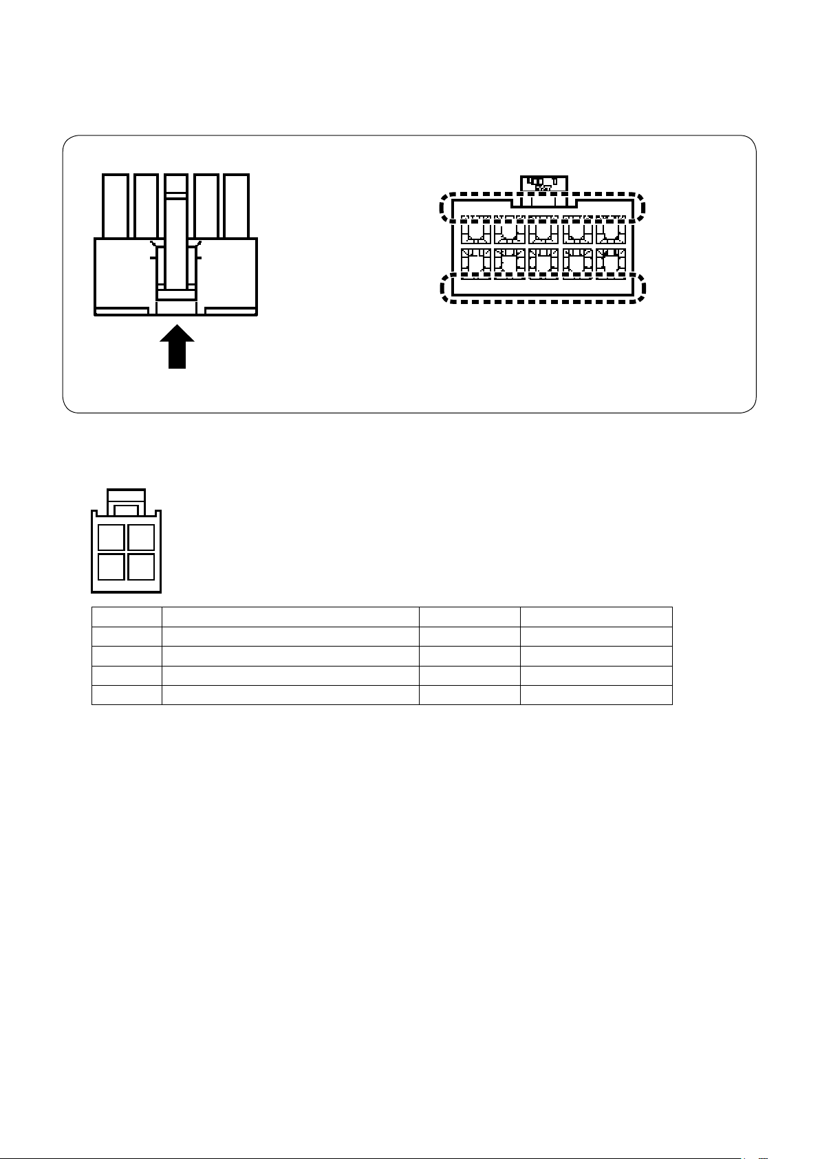
(2) Details of connectors
This clause explains details of connectors ① to ⑤,
gram. Identify the connector pin number as described below.
Connector
The numeric character indicated
on the connector, as viewed
from the direction of the arrow,
is the connector pin number.
CN158: 4P connector (alternate up/down switch)
①
-1
and layout of the pins shown in the wiring dia-
⑤
10 9 7 6
5 4 3 2 1
You may nd the numeric characters indicat-
ed on the connector when viewing from the
direction of the arrow.
4 3
2 1
Pin No. Part name Color of cable Remarks
1 Alternate up/down limit switch (lower side) White
2 Alternate up/down limit switch (upper side) Red
3 Alternate up/down limit switch (lower side) Black GND
4 Alternate up/down limit switch (upper side) Green GND
* When connecting the connectors to the control box, prepare a junction cord using the below-stated connector pin terminal.
Part number of the target connector: HK034620040 (MOLEX: 5559-04P)
Part number of the target pin terminal: HK034630000 (MOLEX: 5558TL)
– 11 –
Page 14
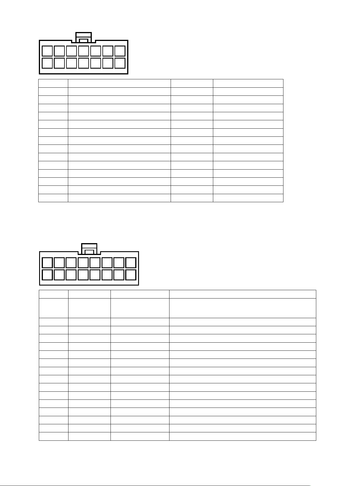
CN36: 14P connector (solenoid, switch)
②
9 811 101214 13
2 14 357 6
Pin No. Part name Color of cable Remarks
1 Tension release solenoid (lower side) Black
2 Tension release solenoid (upper side) Black
3
4 Knee switch White
5 Reverse feed switch Black
6
7 Thread trimming solenoid Black
8 Tension release solenoid (lower side) White Power supply (+27 V)
9 Tension release solenoid (upper side) White Power supply (+27 V)
10 FG (earth cord) Green / Yellow FG
11 Knee switch Black GND
12 Reverse feed switch White GND
13
14 Thread trimming solenoid White Power supply (+27 V)
- - -
- - -
- - -
* When connecting the connectors to the control box, prepare a junction cord using the below-stated connector pin terminal.
Part number of the target connector: HK034620140 (MOLEX: 5559-14P)
Part number of the target pin terminal: HK034630000 (MOLEX: 5558TL)
CN144: 16P connector (6-gang switch)
③
16
8
Pin No. Part name Color of cable Remarks
1 6-gang switch Orange (red dot 1)
2 6-gang switch Orange (black dot 1) SW1 (DLSW)
3 6-gang switch Gray (red dot 1) SW2 (Automatic reverse feed prohibition switch)
4 6-gang switch Gray (black dot 1) SW3 (One-stitch correction switch)
5 6-gang switch White (red dot 1) SW4 (Pitch changeover switch)
6 6-gang switch White (black dot 1) SW5 (Thread tension changeover switch)
7 6-gang switch Yellow (red dot 1) SW6 (Thread clamp switch)
8 6-gang switch Yellow (black dot 1) GND
9 6-gang switch Pink (red dot 1) LED1 (DLSW LED)
10 6-gang switch Pink (black dot 1) LED2 (Automatic reverse feed prohibition switch LED)
11 6-gang switch Orange (red dot 2) LED3 (One-stitch correction switch LED)
12 6-gang switch Orange (black dot 2) LED4 (Pitch changeover switch LED)
13 6-gang switch Gray (red dot 2) LED5 (Thread tension changeover switch LED)
14 6-gang switch Gray (black dot 2) LED6 (Thread clamp switch LED)
15 6-gang switch White (red dot 2) SW7 (Machine head fall sensor)
16
- - -
10 912 111315 14
2 14 357 6
+5V * Do not connect the +24V connector. If the +24V
connector is connected to this switch, the LED
burnout can occur.
* When connecting the connectors to the control box, prepare a junction cord using the below-stated connector pin terminal.
Part number of the target connector: HK034620160 (MOLEX: 5559-16P)
Part number of the target pin terminal: HK034630000 (MOLEX: 5558TL)
– 12 –
Page 15
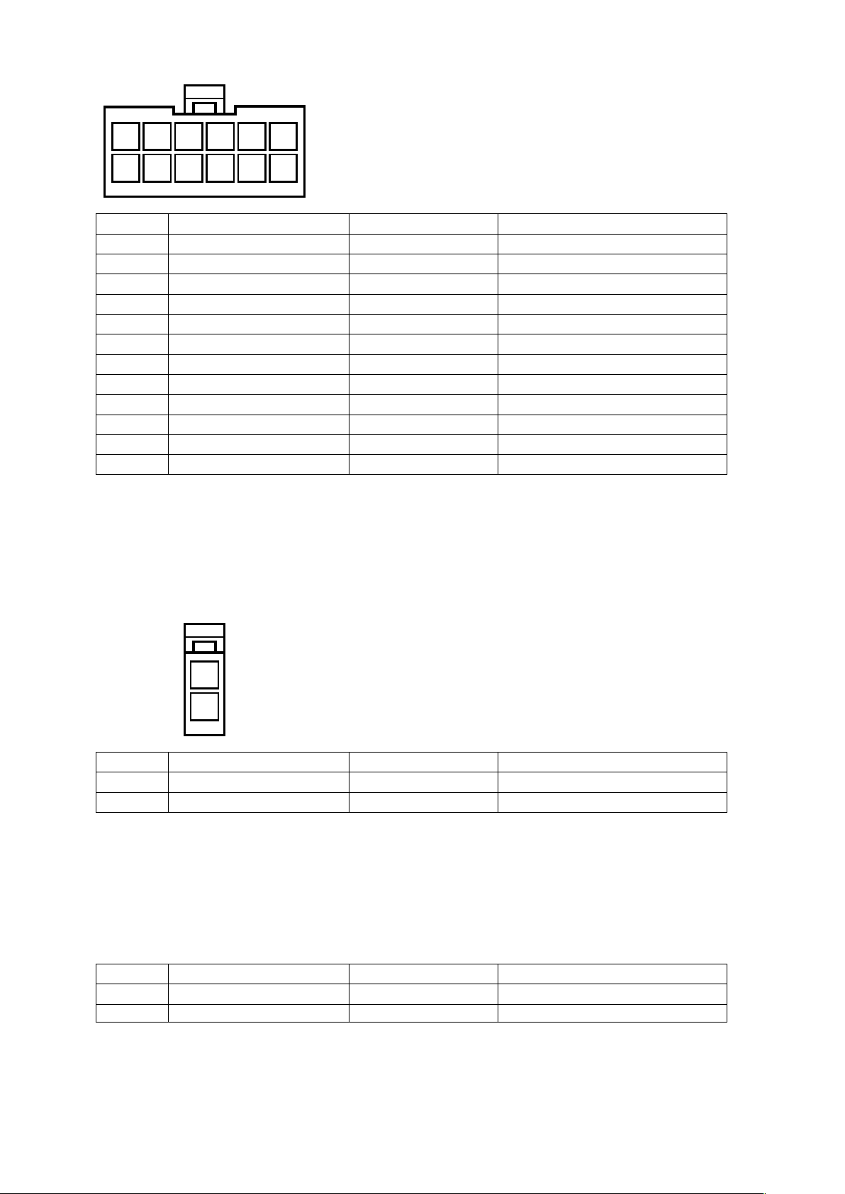
CN102: 12P connector (Solenoid valve)
④
8 710 91112
2 14 356
Pin No. Part name Color of cable Remarks
1 Solenoid valve (CN151) Black Presser bar lifting cylinder
2 Solenoid valve (CN152) Black Reverse feed cylinder
3 Solenoid valve (CN153) Black Alternate up/down cylinder
4 Solenoid valve (CN154) Black Condensation stitch cylinder
5 Solenoid valve (CN155) Black 2-pitch cylinder
6 Solenoid valve (CN156) Black 2.5-pitch cylinder
7 Solenoid valve (CN151) Red +24V
8 Solenoid valve (CN152) Red +24V
9 Solenoid valve (CN153) Red +24V
10 Solenoid valve (CN154) Red +24V
11 Solenoid valve (CN155) Red +24V
12 Solenoid valve (CN156) Red +24V
* When connecting the connectors to the control box, prepare a junction cord using the below-stated connector pin terminal.
Part number of the target connector: HK034620120 (MOLEX: 5559-12P)
Part number of the target pin terminal: HK034630000 (MOLEX: 5558TL)
CN37: 2P connector (Thread clamp solenoid)
⑤
2
1
Pin No. Part name Color of cable Remarks
1 Thread clamp solenoid Blue
2 Thread clamp solenoid Blue Power supply (+27 V)
* When connecting the connectors to the control box, prepare a junction cord using the below-stated connector pin terminal.
Part number of the target connector: HK034620020 (MOLEX: 5559-02P)
Part number of the target pin terminal: HK034630000 (MOLEX: 5558TL)
-1 CN37A: 2P connector (Thread clamp solenoid junction cord)
⑤
Pin No. Part name Color of cable Remarks
1 Thread clamp solenoid Blue
2 Thread clamp solenoid Blue Power supply (+27 V)
* Thread clamp solenoid junction cord is shipped with assembled in the machine head.
– 13 –
Page 16
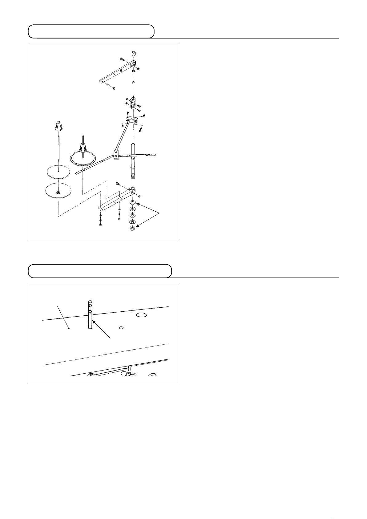
2-9. Installing the thread stand
Assemble the thread stand, set it up on the machine
table using the installation hole in the table and tight-
en nut ❶ gently.
2-10. Installing the thread guide pin
❷
❶
❶
Insert needle thread guide pin ❶ into the corre-
sponding hole in top cover ❷.
– 14 –
Page 17

3. PREPARATION OF THE SEWING MACHINE
3-1. Lubrication
WARNING :
1. Do not connect the power plug until the lubrication has been completed so as to prevent accidents
due to abrupt start of the sewing machine.
2. To prevent the occurrence of an inammation or rash, immediately wash the related portions if oil
adheres to your eyes or other parts of your body.
3. If oil is mistakenly swallowed, diarrhea or vomitting may occur. Put oil in a place where children
cannot reach.
■ Lubrication procedure
Fill the oil tank with oil before operating the sewing
machine.
1) Fill the oil tank with JUKI NEW DEFRIX OIL
No.1 (Part No. : MDFRX1600C0) or JUKI MA-
CHINE OIL #7 (Part No. : MML007600CA) using
the oiler supplied with the machine from section
.
C
2) Fill the oil tank with the oil until the top end of
oil amount indicating rod ❷ comes between the
upper engraved marker line A and the lower
engraved marker line B of oil amount indicating
window ❶.
If the oil is lled excessively, it will leak from the
air vent hole in the oil tank or proper lubrication
will be not performed. In addition, when the oil
is vigorously lled, it may overow from the oil
hole. So, be careful.
3) When you operate the sewing machine, rell
oil if the top end of oil amount indicating rod ❷
comes down to the lower engraved marker line
of oil amount indicating window ❶.
B
❶
C
A
❷
B
1. When using a new sewing machine for the rst time or using the sewing machine which has not
been used for a long time, run in the sewing machine at a sewing speed of 1,000 sti/min or less and
check the oil quantity in the hook before use.
In the case the oil does not come from the hook, turn the oil amount adjusting screw counterclock-
wise to make sure that the oil is fed from the hook. After that, adjust the amount of the oil fed from
the hook appropriately. (Refer to "■ Adjusting the oil quantity in the hook" p.16)
2. For the oil for hook lubrication, purchase JUKI NEW DEFRIX OIL No. 1 (Part No. : MDFRX1600C0) or
JUKI MACHINE OIL #7 (Part No. : MML007600CA).
3. Be sure to lubricate clean oil.
– 15 –
Page 18

❷
❸
❶
❺
❹
■ Cleaning the oil lter
1) Loosen fastening plate ❶ on the back-ow side.
Remove oil lter joint (asm.) ❷ on the back-ow
side.
2) Clean up lters ❸, ❹ and ❺ and oil reservoir
of the oil pan.
❻
Be sure to clean up the oil reservoir of the
oil pan and the lter case approximately
once a month.
If the lter is clogged with soil, lubrication
fails resulting in trouble.
A sheet of
paper
❷
❻
■ Adjusting the oil quantity in the hook
1) Remove rubber cap❶.
2) Loosen nut ❷ and turn oil amount adjustment
screw ❸ to adjust the amount of oil in the hook.
Turning the screw clockwise A will decrease the
amount of oil in the hook or counterclockwise B
will increase it.
3) The appropriate amount of oil, when a sheet of
paper is placed near the periphery of the hook,
is to such an extent that splashes of oil from the
❶
B
A
❸
❹
hook appear in approximately ve seconds as
shown in the gure on the left.
In the case the oil quantity in the hook
cannot be adjusted to the proper quantity,
it should be adjusted by loosening nut ❹
and turning oil quantity adjusting screw ❺.
The oil quantity in the hook is increased
by turning the oil quantity adjusting screw
counterclockwise C, or is decreased by
turning it clockwise D.
Also check to be sure that the oil is fed to the
hook at the sewing speed of 1,000 sti/min.
D
C
– 16 –
❺
Page 19

3-2. Attaching the needle
WARNING :
To protect against possible personal injury due to abrupt start of the machine, be sure to start the
following work after turning the power off and ascertaining that the motor is at rest.
❷
❶
Long groove
Switch "off" the motor.
Use 134-35 needles.
1) Turn the handwheel to bring the needle bar to
the highest position of its stroke.
2) Loosen needle clamp screw ❷ and hold needle
so that its long groove faces exactly to the
❶
right.
3) Push needle ❶ deep into the needle clamp hole
until it will go no further.
4) Tighten needle clamp screw ❷ rmly.
When replacing the needle, check the clearance provided between the needle and the
blade point of hook. (Refer to "4-5. Needle-
to-hook relation" p.28 and "4-6. Adjusting
the hook needle guard" p.29.)
If there is no clearance, the needle and the
hook will be damaged.
3-3. Attaching and removing the bobbin
WARNING :
To protect against possible personal injury due to abrupt start of the machine, be sure to start the
following work after turning the power off and ascertaining that the motor is at rest.
❶
1) Lift latch ❶ of hook, and take out the bobbin.
2) Put the bobbin into the shaft in the hook correct-
ly and release the latch ❶.
Do not make the machine run idle with the
bobbin (bobbin thread). The bobbin thread
is caught in the hook. As a result, the hook
may be damaged.
– 17 –
Page 20

3-4. Threading the hook
WARNING :
To protect against possible personal injury due to abrupt start of the machine, be sure to start the
following work after turning the power off and ascertaining that the motor is at rest.
1) Carefully draw the thread through threading slit
of the inner hook and the space provided be-
❶
tween the bobbin case opener and inner hook
to route it below the tension spring.
❷
2) Make sure that the bobbin revolves in the direc-
tion of the arrow when you draw the thread.
❷
❶
3-5. Winding a bobbin
❻
❼
❺
❹
❸
❷
❶
1) Pass the thread through sections ❶ to ❹ in the
numerical order.
2) Insert the thread from the rear side of looper
thread clamp ❺ and trim the thread. (The thread
end is retained under the looper thread clamp.)
3) Load a bobbin on bobbin winder shaft ❻.
4) Lift bobbin winder lever ❼ in the direction of the
arrow.
5) When you start the sewing machine, the bobbin
rotates to automatically wind the thread on itself.
6) When the bobbin is lled up, the bobbin winder
lever ❼ automatically releases the bobbin and
the bobbin winder stops running.
1. The bobbin thread winding amount is adjusted by loosening setscrew ❽. The bobbin thread winding amount is increased
by moving bobbin wider lever ❼ upward.
2. If the thread comes off the thread tension
controller, wind the thread on the intermediate thread guide by one turn.
❽
1. This is the one-touch type bobbin
winder. When the bobbin is fully wound
with thread, bobbin thread clamp ❺
automatically returns to the initial
position.
2. To stop bobbin winding before the bobbin
is fully wound with thread, turn the
handwheel with threading lever ❼ held
lightly depressed to return bobbin thread
clamp ❺ to the initial position.
– 18 –
Page 21

3-6. Threading the machine head
WARNING :
To protect against possible personal injury due to abrupt start of the machine, be sure to start the
following work after turning the power off and ascertaining that the motor is at rest.
❷
❶
❾
❽
❸
❹
❺
❻
❸
❹
❺
❼
❻
❼
Thread the machine head following the order as
illustrated in the gure.
– 19 –
Page 22

3-7. How to set the model of the machine head (LU-2828-7)
CP-18
•
1) Call Function Setting No. 95 in
reference to
"III-6. Function Setting
of SC-922" in the Instruction Manual
for the SC-922
.
❺❹❸
❻
2) The type of machine head can be se-
lected by pressing
switch ❺ (
switch ❻).
In this step of procedure, select
"L28d".
❺❹❸
❻
3) After selecting the type of machine
head, by pressing switch ❸ (
switch ❹), the step proceeds to 94
or 96, and the display automatically
changes to the contents of the
setting corresponding with the type of
machine head.
❺❹❸
❻
4) Turn the power OFF.
– 20 –
Page 23

CP-180
•
❶
1) Refer to
in the Instruction Manual for the CP-180
"18. FUNCTION SETTING SWITCH"
, and
call the function setting No. 95.
2) The type of machine head can be selected by
pressing switch ❶.
In this step of procedure, select "L28d".
3) After selecting the type of machine head, by
pressing switch ❷, the step proceeds to 96 or
94, and the display automatically initializes to
the contents of the setting corresponding with
the type of machine head.
4) Turn the power OFF.
❷
– 21 –
Page 24

CP-18
•
3-8.
Adjusting the machine head
A
(LU-2828-7)
1) Simultaneously pressing switch
❸
❹
and
switch ❺, turn ON the
power switch.
2) is displayed A in the indicator
and the mode is changed over to the
adjustment mode.
❺❹
❻
B
3) Turn the pulley of the machine head
by hand until the main-shaft reference
signal is detected. At this time, the
degree of an angle from the main-shaft
reference signal is displayed on the
indicator B.
(The value is the reference value.)
❺❹❸
❻
❽
4) In this state, align one of the marker
dots ❼ on the pulley with marker line
on the pulley cover as shown in the
❽
❼
gure.
5) Press switch ❻ to nish the
adjustment work. (The value is the
reference value.)
6) Turn the power OFF.
❺❹❸
❻
When checking the adjustment result, set "Function setting No. 90; Initial sewing machine movement
function" at "1: Initial operation - Sewing machine stops with its needle up". Then, check whether or not
marker dot ❼ is aligned with marker line ❽. If they are not aligned, carry out the adjustment again.
After checking the adjustment result, return the setting of No. 90 to the previous setting. (Initial value is
"2. Initial operation: Sewing machine turns in the reverse direction and stop with its needle up".)
For the function setting procedure, refer to "III-6. How to set the functions of the SC-922" in the Instruction Manual for the SC-922.
– 22 –
Page 25

CP-180
•
1) Simultaneously pressing switch ❶ and switch
, turn ON the power switch.
❷
❷❶
❽
2)
BA
is displayed A in the indicator and the
mode is changed over to the adjustment mode.
3) Turn the pulley of the machine head by hand
until the main-shaft reference signal is detected.
At this time, the degree of an angle from the
main-shaft reference signal is displayed on the
indicator B.
(The value is the reference value.)
4) In this state, align one of the marker dots ❼
on the pulley with marker line ❽ on the pulley
cover as shown in the gure.
❼
❹
5) Press switch ❹ to nish the adjustment work.
(The value is the reference value.)
6) Turn the power OFF.
When checking the adjustment result, set
"Function setting No. 90; Initial sewing machine movement function" at "1: Initial operation - Sewing machine stops with its needle
up". Then, check whether or not marker dot
is aligned with marker line ❽. If they are
❼
not aligned, carry out the adjustment again.
After checking the adjustment result, return
the setting of No. 90 to the previous setting.
(Initial value is "2. Initial operation: Sewing
machine turns in the reverse direction and
stop with its needle up".)
For the function setting procedure, refer to
"18. How to set the functions" in the Instruction Manual for the CP-180.
– 23 –
Page 26

4. ADJUSTING THE SEWING MACHINE
4-1. Adjusting the stitch length
Turn standard feed adjusting dial ❶ and 2P feed ad-
❹
❸
❷
❸
❶
justing dial ❷ to align the desired number with mark-
er dot ❸ on the machine dial.
(1) Reverse feed stitchng
1) Press down reverse feed control lever ❹.
2) Reverse feed stitches are made as long as you
keep pressing the lever down.
3) Release the lever, and the machine will run in
the normal feed direction.
(2) Manual one-touch reverse feed stitching
1) Press touch-back switch ❺.
2) Reverse feed stitches are made as long as you
keep pressing the lever down.
3) Release the switch, and the machine will run in
the normal feed direction.
❻
❺
(3) Changing over the stitching pitch
1) Press stitching pitch changeover switch ❻ to
change over the stitch length to the one cor-
responding to the scale mark on the 2P feed ad-
justing dial. (The LED on the switch lights up.)
1. Set 2P feed adjusting dial ❷ at a value
smaller than the value set by standard
feed adjusting dial
2. Adjust the 2P feed adjusting dial when
the stitching pitch changeover switch is
placed in OFF.
3. Scale mark on the 2P feed adjusting
dial smaller than 3 (at which the dial is
stopped by the dial stopper) is used for
the 0 (zero) alignment of the 2P dial. Scale
marks smaller than 3 cannot be used.
Refer to "5-6. Operation switches" p.38
for the details of the 2P device.
.
❶
– 24 –
Page 27

4-2. Thread tension
(1) Adjusting the needle thread tension
D
B A
C
1) Turn thread tension nut No. 1 ❶ clockwise A to
shorten the length of thread remaining on the
top of needle after thread trimming. Turn the nut
❶
❷
counterclockwise B to lengthen it.
2) Turn thread tension nut No. 2 ❷ clockwise C to
increase the needle thread tension, or counter-
clockwise D to decrease it.
Apply the same tension to both of the
thread tension nut No. 2.
WARNING :
To protect against possible personal injury due to abrupt start of the machine, be sure to start the
following work after turning the power off and ascertaining that the motor is at rest.
(2) Adjusting the bobbin thread tension
Turn tension adjustment screw ❸ clockwise A to
increase the bobbin thread tension, or counterclock-
wise B to decrease it.
❸
A
B
– 25 –
Page 28

4-3. Thread take-up spring
❷
❶
(1) When you want to change the stroke of the
thread take-up spring
Loosen screw ❷. Adjust thread take-up spring ❶ by
moving it in the slot.
Decrease
❶
❹
❸
(2) When you want to change the tension of
the thread take-up spring
To adjust the tension of thread take-up spring ❶,
loosen nut ❸ first. Turn spring shaft ❹ counter-
clockwise to increase the tension or clockwise to de-
crease it.
After the adjustment, x the stud by tightening nut ❸.
Increase
– 26 –
Page 29

4-4. Adjusting the pressure of the presser foot
Turn presser spring regulating dial ❶ clockwise A to
B
A
increase the pressure of the presser foot, or counter-
clockwise B to decrease it.
A
❶
Be sure to operate the sewing machine with
the pressure of the presser foot minimized
as long as the presser foot securely holds
the material.
The adjustable range extends from 38 mm to 60 mm
which represents the distance from the upper sur-
face A of the arm to presser spring regulating dial ❶.
The standard value at the time of shipment is 47
mm.
– 27 –
Page 30

4-5. Needle-to-hook relation
WARNING :
To protect against possible personal injury due to abrupt start of the machine, be sure to start the
following work after turning the power off and ascertaining that the motor is at rest.
1.5 mm
❷
❶
Hook driving shaft
setting collar
❸
❹
❺
2.3 mm
0.05 to 0.1 mm
Hook driving
shaft C
The hook driving shaft setting
collar is aligned with the end
face of hook driving shaft C
1) Adjust the standard feed adjusting dial to "0".
2) Loosen hook driving shaft set collar clamping screw ❸, and turn the handwheel counterclockwise to
make the needle bar ascend by 2.3 mm from the lowest position of its stroke.
3) In the state described in 2), align blade point ❶ of the hook with the center of needle ❷, and tighten
hook driving shaft set collar clamping screw ❸. At this time, a clearance of 1.5 mm is provided be-
tween the blade point of the hook and the top end of the needle eyelet. (The hook driving shaft setting
collar must be aligned with the end face of hook driving shaft C.)
4) Loosen setscrews ❹ and ❺ of the hook driving shaft saddle on the top face of the bed. Adjust the clear-
ance between the blade point of the hook and the needle to 0.05 to 0.1 mm by moving the hook driving
shaft saddle to the right or left to change its position. Then, tighten setscrews ❹ and ❺.
5) Align the largest scale mark of the standard feed adjusting dial with the marker dot on the machine arm.
Check to be sure that the blade point of the hook does not come in contact with the needle.
The operation panel could come in contact with the thread stand when tilting the machine head. To
protect the relevant parts from contact, shift the thread stand to a position at which the thread stand
does not interfere with the control panel.
To check the needle bar position as described in the aforementioned 2) [i.e., "...the needle bar ascend
by 2.3 mm from the lowest position of its stroke"], you may use the display of the main shaft rotation
angel under the "machine head adjustment mode" of the SC-922.
Increase the numerical value displayed when the needle bar is in its lowest position of its stroke under
the "machine head adjustment mode" by 25 degrees of an angle, the needle bar goes up by 2.3 mm.
(When the needle bar ascends by 2.3 mm from its lowest position of its stroke, the m
angle is 25 degrees of an angle.)
* In the case of adjusting the needle-to-hook relation under the "machine head adjustment mode", do
not press switch.
Refer to "II-10. Adjustment of the machine head" in the Instruction Manual for the SC-922 for the ma-
chine head adjustment mode.
ain shaft rotation
– 28 –
Page 31

4-6. Adjusting the hook needle guard
WARNING :
To protect against possible personal injury due to abrupt start of the machine, be sure to start the
following work after turning the power off and ascertaining that the motor is at rest.
❹
❶
❷
0.05 to
0.2 mm
a
B
b
❸
When a hook has been replaced, be sure to check
the position of the hook needle guard.
As the standard position of the hook needle guard,
A
hook needle guard ❷ must push the side face of
needle ❶ to lean the needle by 0.05 to 0.2 mm away
from its straight position.
If the state of the hook is not as shown above, fit
hexagon wrench ❹ into ❸ of needle guard adjusting
screw and adjust as follows:
1) To bend the hook needle guard in direction a, turn
the needle guard adjusting screw in direction A.
2) To bend the hook needle guard in direction b, turn
the needle guard adjusting screw in direction B.
3) At the nal step of procedure, appropriately adjust
the clearance provided between the needle and
the hook.
4-7. Adjusting the bobbin case opening lever
WARNING :
To protect against possible personal injury due to abrupt start of the machine, be sure to start the
following work after turning the power off and ascertaining that the motor is at rest.
1) Turn the handwheel in its normal rotational di-
2) Turn inner hook ❷ in the direction of the arrow
3) Loosen setscrews ❺ of the bobbin case open-
❹
❶
❸
❷
0.7 to 0.9 mm
A
rection to bring bobbin case opening lever ❶ to
its back end position.
until stopper ❸ is pressed against the slits in
throat plate ❹.
ing lever sleeve. Adjust the clearance provided
between the bobbin case opening lever and
the projection A of the bobbin case to 0.7 to 0.9
mm. Tighten setscrews ❺ while pressing bobbin
case opening lever ❶ downward and pressing
the bobbin case holding lever sleeve ❻ upward.
❻
❺
– 29 –
Page 32

4-8. Adjusting the moving knife, the counter knife and the bobbin thread clamp
WARNING :
To protect against possible personal injury due to abrupt start of the machine, be sure to start the
following work after turning the power off and ascertaining that the motor is at rest.
• Adjusting the counter knife position
End face of the auxiliary cover
End face of the
auxiliary cover
❶
37.8 mm
Adjust so that the top end of counter knife ❶ is
spaced 37.8 mm from the end face of the auxiliary
cover. Then, x the counter knife by tightening screw
.
❷
❸
❷
• Checking the position of the moving knife
❹
1) Adjust so that a clearance of 0.3 to 0.7 mm is
provided between stopper A and moving knife
. Then, x the moving knife by tightening
❸
screws ❹.
A
0.3 to 0.7 mm
– 30 –
Page 33

❼
❶
❸
1.0 to 2.0 mm
❺
2) Adjust so that a clearance of 1.0 to 2.0 mm is
provided between the top end of moving knife
and that of counter knife ❶ when the moving
❸
knife is in its return end (the moving knife is in
the standby state). Then, x the moving knife by
tightening screw ❺.
(The clearance provided between thread trim-
ming roller ❻ and thread trimming cam ❼ is
0.02 to 0.1 mm.
❻
0.02 to 0.1 mm
• Adjusting the knife pressure
Loosen screws ❽. Adjust the knife pressure by
moving counter knife ❾ up or down.
❾
❽
0.1 to 0.3 mm
• Adjusting the position of the bobbin thread
clamp
Loosen screw . Adjust the lateral position of the
clamp arm so that a clearance of 0.1 to 0.3 mm is
provided between the clamp arm and the moving
knife.
– 31 –
Page 34

• Adjusting the bobbin thread clamp pressure
Loosen screw . Adjust the clamp pressure by turn-
ing cramp arm in the direction of the arrow.
Adjust the clamp pressure so that the bobbin thread
comes off at the pressure of 0.3 N.
4-9. Adjusting the thread trimming cam timing
WARNING :
To protect against possible personal injury due to abrupt start of the machine, be sure to start the
following work after turning the power off and ascertaining that the motor is at rest.
Bring the moving knife to its front end. At this time,
position the thread trimming cam so that the two
marker dots on the handwheel align with the marker
line of the motor cover. Then, tighten thread trimming
cam setscrew ❷ to x thread trimming cam ❶.
❷
❶
– 32 –
Page 35

4-10. Adjusting the condensation stitch
WARNING :
To protect against possible personal injury due to abrupt start of the machine, be sure to start the
following work after turning the power off and ascertaining that the motor is at rest.
❶
❷
5.2 ± 0.5 mm
1) Adjust the distance from condensation stitch pin
to nut ❷ to 5.2 ± 0.5 mm.
❶
Condensation
stitch arm
❹
❽
❸
2) Set stitch dial ❸ at the pitch corresponding to
the condensation amount you want to set.
(Pitch 2 in the case of condensation amount of
2 mm)
Loosen condensation stitch arm bracket screw
.
❹
3) Turn ON the condensation stitch cylinder ❽.
In this state, tighten condensation stitch arm
bracket screw ❹.
❹
– 33 –
4)
The condensation stitch amount can be set up to
-3 mm (reverse feed stitch).
If the condensation amount is excessively
small, the material can be torn depending on
the type of seam to cause stitch skipping.
This can cause a thread trimming failure.
Page 36

4-11. Adjusting the amount of the alternating vertical movement of the walking
foot and the presser foot
Adjust the amount of the alternating vertical move-
❶
ment of the walking foot and the presser foot using dial ❶. Turn the dial clockwise to increase the
amount of the alternating vertical movement of the
walking foot and the presser foot, or counterclockwise to decrease it.
When sewing a heavy-weight material, set
the dial at a large value. If the dial is set at a
small value, the feed amount of the walking
foot will decrease, resulting in faulty stitches
and a thread trimming failure because the
needle can bend.
5. OPERATION OF THE SEWING MACHINE
5-1. Hand lifter
To lift the presser foot manually, pull hand lifter ❶ in
the direction of the arrow.
This makes the presser foot rise 10 mm and stay at
❶
that position.
5-2. Resetting the safety clutch
WARNING :
To protect against possible personal injury due to abrupt start of the machine, be sure to start the
following work after turning the power off and ascertaining that the motor is at rest.
❶
The safety clutch functions when an excessive load
is applied to the hook or the other components during sewing. At this time, the hook will never rotate
even if turning the handwheel. When the safety
clutch has functioned, remove the cause and reset
the safety clutch as given in the following procedure.
1) Pressing push button ❶ located on the top
surface of the machine bed, strongly turn the
handwheel in the reverse direction of rotation.
2) The resetting procedure completes when the
handwheel clicks.
Turn the handwheel by hand, and confirm
that push button ❶ has returned.
3) At the nal step of procedure, check the needle-
"4-5. Needle-to-hook
– 34 –
to-hook relation. (Refer to
relation" p.28
)
Page 37

5-3. Adjusting the automatic presser foot lifter
WARNING :
To protect against possible personal injury due to abrupt start of the machine, be sure to start the
following work after turning the power off and ascertaining that the motor is at rest.
1) Turn the power ON. Carry out thread trimming
2) Place a 20 mm spacer ❶ under the presser
3) Turn the power OFF.
❶
4) Remove rubber cap ❷ from the rear face of the
5) Turn presser bar lifting arm ❹ in the direction of
once. Turn ON the automatic presser lifter.
foot.
machine arm. Loosen setscrew ❸.
the arrow until it will go no further. Then, tighten
setscrew ❸.
❷
❸
❹
– 35 –
Page 38

5-4. Fixing the feed adjusting dial
❷
❶
❸
To prohibit the adjustment of the feed adjusting
dial:
1) Remove the motor cover or the belt cover.
2) Insert stopper pin ❸ and screw ❹ in tapped
holes ❶ and ❷, and tighten it. Stopper pin ❸
should be inserted into the tapped hole so that
its thinner tip is inserted rst.
❹
Stopper pin ❸ and screw ❹ are separately
available.
Part number of stopper pin : TA0440401MO
Part number of screw : SM8060612TP
– 36 –
Page 39

5-5. Normal-/reverse-feed stitch needle entry points alignment at the time of
automatic reverse feed stitching
When the sewing speed or stitch pitch is changed, the normal- and reverse-feed stitch needle entry points
may not be aligned at the time of automatic reverse feed stitching.
In such a case, correct the alignment of needle entry points by changing the ON/OFF timing of the automatic
reverse feed cylinder. If it is difcult to correct the timing of the automatic reverse feed cylinder because of
the large stitch pitch, it is recommended to decrease the reverse feed stitching speed.
Refer to
"III-8. Detailed explanation of selection of functions
noid for reverse feed stitching" in the Instruction Manual for the SC-922
The forward/reverse stitches need to be adjusted depending on the stitch pitch to be used. Refer to
gineer's Manual
for how to adjust the stitch pitch.
1) How to align needle entry points of the reverse feed stitching with those of the normal feed stitching
Carry out "correction of the timing of the reverse feed stitching" according to the difference between the
needle entry points of the reverse feed stitching and those of the normal feed stitching.
Refer to
"III-6. Setting the SC-922 functions" in the Instruction Manual for the SC-922
carry out the "correction of the timing of the reverse feed stitching".
Compensation of timing of the sole-
⑯
for detail.
for how to
the En-
ON-timing of the reverse feed
①
Sewing starting position
stitching at the beginning of
sewing (Function setting No. 51)
Stitch length
is smaller
Decrease the set
value of No. 51.
Correction of the OFF-timing of
②
Stitch length is
smaller
Increase the set
value of No. 51.
Stitch length is smaller
the reverse feed stitching at the
beginning of sewing (Function
setting No. 52)
Decrease the set
value of No. 52.
Correction of the OFF-timing of
③
the reverse feed stitching at the
Stitch length is
smaller
Increase the set
value of No. 52.
end of sewing (Function setting
No. 53)
Sewing end
position
Decrease the set
value of No. 53.
2) Reverse feed stitching speed on the basis of stitch pitch
This speed can be changed using Function setting No. 8.
Default value Recommended value Recommended value
Stitch pitch (mm) 3 to 6 7 to 8 9
Reverse feed stitching speed (sti/min) 600 500 400
– 37 –
Sewing end
position
Increase the set
value of No. 53.
Page 40

5-6. Operation switches
Alternating vertical movement amount
❶
change-over switch
If this switch is pressed the amount of the
alternating vertical movement of the walking foot
and the presser foot will be maximized. (Lamp
above the switch lights up)
Use this switch when a multilayered portion of
the sewing product is not smoothly fed.
To change over the amount of the alternating
❶ ❷ ❸ ❹ ❺ ❻
Automatic reverse feed stitching cancellation/addition switch
❷
• If this switch is pressed when the following automatic reverse feed stitching has been specied, the
reverse stitching will not take place (for once immediately after it is pressed). (Example 1)
• If this switch is pressed when no automatic reverse feed stitching has been specied, the reverse feed
stitching will take place (once immediately after it is pressed). (Example 2)
vertical movement of the walking foot and the
presser foot by means of the knee switch,
join the knee switch and the mounting plate,
supplied with the unit, together and x them on
the table with wood screw.
For the wiring, refer to
p.40
.
"5-7. Knee switch"
(Example 1) In the case where both automatic reverse feed stitching for start and that for end
have been specied :
A
B
C
D
C
D
If the switch is pressed before starting sewing, the automatic reverse feed stitching for
start (between A and B) will not be carried out.
A
B
C
D
If the switch is pressed during sewing, the
automatic reverse feed stitching for end (between C and D) will not be carried out.
A
B
(Example 2) In the case where neither automatic reverse feed stitching for start nor that for end
have been specied :
A
B
If the switch is pressed before starting
sewing, the automatic reverse feed stitching
for start (between A and B) will be carried out.
– 38 –
C
D
If the switch is pressed during sewing, the
automatic reverse feed stitching for end (between C and D) will be carried out.
Page 41

Needle lifting switch
❸
When the switch is pressed, the needle moves from its lower-end stop position to its upper-end stop position.
When raising the machine head which has been tilted, do not hold the operation switch to raise it.
2P switch
Example
2P feed adjusting dial
・
scale : 6
❹
If this switch is pressed, the stitch length is
changed over to that of the scale on the 2P feed
adjusting dial. (Lamp in the button is lit up.)
Be sure to make the number of 2P feed
adjusting dial less than that of the standard
Standard feed adjusting
・
dial scale : 9
When this switch is pressed, the stitch length is
・
changed over from 9 to 6 and the lamp lights up.
feed adjusting dial.
OFF ON
When this switch pressed again, the stitch length
・
returns from 6 to 9 and the lamp goes out.
Needle thread clamp
function is OFF
The state of the
needle thread at the
beginning of sewing
is changed.
Needle thread clamp
function is ON
Needle thread tension changeover switch
❺
When the switch is pressed, the double tension
function is selected to increase the needle thread
tension. (The lamp above the switch is lit up.)
Needle thread clamp changeover switch
❻
When this switch is pressed, the needle thread
clamp function is turned OFF.
(The lamp above the switch is lit up.)
The needle thread clamp device as well as the
presser foot lifting motion does not function until
the thread trimming is performed after turning
ON the power.
In addition, when the presser foot is lifted after
thread trimming motion, the needle thread is
clamped with the needle thread clamp device,
but when the needle thread clamp switch is
turned OFF, the needle thread is released.
– 39 –
In the case the needle thread slips off the
needle eyelet when the needle thread clamp
function is turned OFF, change the needle
thread clamp with the accessory needle
thread clamp (asm.).
Page 42

5-7. Knee switch
WARNING :
To protect against possible personal injury due to abrupt start of the machine, be sure to start the
following work after turning the power off and ascertaining that the motor is at rest.
(1) Installation of the knee switch
❶
❸
White line
Black (No. 11)
14
8
❷
❹
❺
White (No. 4)
7
1
1) Install knee switch mounting plate ❶ on the
underside of the table with wood screw ❷ sup-
plied with the unit.
2) Install knee switch ❸ on knee switch mounting
plate ❶ with tapping screw ❹ and washer ❺
supplied with the unit so that the cord of knee
switch ❸ is brought to the downside of the
switch.
3) Connect the knee switch to #4 and #11 pins of
the machine connector 14P which is connected
to CN36 of the machine controller.
(2) Functions of the knee switch
If knee switch ❸ is pressed, the amount of the al-
ternating vertical movement of the walking foot and
the presser foot will be maximized. (Same with the
performance carried out by pressing the alternating
vertical movement amount change-over switch “ ”
on the machine head.)
The knee switch can be used as the presser lifting
switch by setting of the motor. (When the switch is
used as the presser lifting switch, the function as the
alternating vertical movement amount changeover
switch is lost.)
Black line
Cords of knee switch
– 40 –
Page 43

(3) Function setting of the knee switch
CP-18
・
1 2 TPo _
Po T _ni _
3i 1 rEv T
The lamps will be
on alternately.
3i 1
2L 4
2L 4
❸❷❶
1) Enter the function setting mode referring to
SC-922, 1)" in the Instruction Manual for the SC-922
❹
"6. Setting of functions of
.
2) Press switch ❶ or switch ❷ to call out function setting No.12
(option input/output function selection).
3) Press switch ❸ or switch ❹ and select the item for “in”.
4) Press switch ❷ and select display No.i31.
5) Press switch ❸ or switch ❹ to select the knee switch
function. Refer to list 1 for the details of the functions.
6) Press switch ❷ and x the function.
Po T i n
nE d
1 2 TPo _
7) Press switch ❷ and end the option input.
8) Select “End” item using switch ❸ or switch ❹.
9) Press switch ❶ or switch ❷ and return to the function setting
mode.
List 1
Function code Abbreviation Functional item Remarks
5 FL Presser lifter switch function Presser output will be ON while the switch is being
pressed.
31 ALFL Presser lifter alternate switch function Presser output will be ON or OFF each time the
switch is pressed.
24 vErT Alternate vertical movement amount
conversion alternate switch function
25 vSW Alternate vertical movement amount
conversion switch function
Alternate vertical movement amount output will be
ON or OFF each time the switch is pressed.
Alternate vertical movement amount output will be
ON while the switch is being pressed.
– 41 –
Page 44

CP-180
・
❶
❷
The lamps will be on alternately.
1) Enter the function setting mode referring to
"18. FUNC-
TION SETTING SWITCH, 1)" in the Instruction Manu-
al for the CP-180.
2) Select function number 12 according to the function
setting method.
3) Select the item of " " by switch❶.
4) Select the displayed number " " by means of switch
.
❷
5) Select the knee switch function by switch❶. Refer to
list 1 for the details of the functions.
6) Fix the knee switch function by switch❷.
7) The above function is xed by switch ❷.
8) The option input is ended by switch ❷.
9) Select the item of " " by switch ❶, and return to
the function setting mode.
– 42 –
Page 45

5-8. Function setting for the SC-922 (LU-2828-7)
This section describes how to set the functions of the SC-922 specic to the LU-2828-7 (shorter-remaining-thread type).
Refer to
"6. Function setting for the SC-922" in the Instruction Manual for the SC-922
.
Function setting list
No Item Description
154 Condensation
stitching
function for
beginning/end
of sewing
156 Needle thread
clamp function
158 Condensation
stitching
function during
thread trimming
173 Thread clamp
ON retention
time
Enabled when the SC-922 is used in combination with the machine head provided with condensation stitching function for
thread trimming leaving shorter thread on the material.
The sewing machine performs condensation stitching at the
beginning and end of sewing.
(Condensation stitching is performed instead of automatic reverse feed stitching.)
0 : The function is disabled
1 : The function is enabled
Enabled when the SC-922 is used in combination with the machine head provided with the needle thread clamp function.
Selects the status of the needle thread clamp function.
0 : Enable/disable is changed over with the operation en-
abling switch
1 : Disables the needle thread clamp function
2 : Forcibly enables the needle thread clamp function
Enabled when the SC-922 is used in combination with the
machine head provided with condensation stitch function for
thread trimming leaving shorter thread on the material.
Selects whether or not the condensation stitch for thread trimming leaving shorter thread on the material is output.
0 : The function is disabled
1 : The function is enabled
The length of time during which the thread clamp is retained in
ON state is set.
Setting
range
0/1
0 to 2
0/1
1 to 60
(sec.)
Indication of function
setting
1 5 4
1 5 6
1 5 8
1 7 3
0
0
1
3
196 Condensation
stitching
function at the
beginning of
sewing
197 The number of
condensation
stitches at the
beginning of
sewing
Enabled when the SC-922 is used in combination with the
machine head provided with condensation stitch function for
thread trimming leaving shorter thread on the material.
Condensation stitching is carried out at the beginning of sewing.
0 : The function is disabled
1 : The function is enabled
2 : The function is enabled when the reverse feed stitching
at the beginning of sewing is disabled. The function is
disabled when the reverse feed stitching at the beginning of sewing is enabled.
The number of condensation stitches to be sewn at the
beginning of sewing.
0 to 2
0 to 19
(stitches)
1 9 6
1 9 7
2
2
– 43 –
Page 46

Details of the function setting
Condensation stitching function for beginning/end of sewing (function setting No. 154)
①
Condensation stitching is carried out at the beginning and end of sewing. Thread fray and stitch skip-
ping which are likely to occur at the beginning and end of sewing can be prevented.
Condensation stitch is carried out at the beginning and end of sewing when the relevant setting item 154
is set to "1" (enable) as well as the reverse-feed stitch pattern enable/disable switch is set to "enable" on
the operation panel CP-18.
0: Condensation stitching function is disabled (initial value)
1: Condensation stitching function is enabled
Press the reverse-feed
stitch pattern enable/
disable switch to set it to
"enable" (LED lights up).
51 4 0
Number of condensation
stitches at the beginning of sewing
Number of condensation
stitches at the end of sewing
* Refer to
"III-3. How to operate the sewing pattern" in the Instruction Manual for the SC-922
for
how to set the number of stitches, etc.
Needle thread clamp function (function setting No. 156)
②
Selection between enable/disable of the needle thread clamp function.
0:
51 6 0
Enable/disable is changed over with the operation enabling switch (initial value)
1: The function is disabled
2: The function is enabled
When the
setting is 0
When the
setting is 1
❶
Condensation stitching function during thread trimming (function setting No. 158)
③
When the
setting is 2
Enable/disable of the thread clamp function
can be selected with needle thread clamp
changeover switch ❶. (Initial value)
Function is disabled regardless of the status of
needle thread clamp changeover switch ❶.
Function is enabled regardless of the status of
needle thread clamp changeover switch ❶.
Enable/disable of the output of condensation stitch for shorter-remaining-thread type thread trimmer
during thread trimmer control is set with the function setting No. 158.
When this setting is set to "0" (condensation stitching function is disabled), the same thread trimming
control as the LU-2810-7 is carried out.
0: Condensation stitching function is disabled
51 8 1
1: Condensation stitching function is enabled (initial value)
Thread clamp ON retention time (function setting No. 173)
④
The length of time during which the ON state of the thread clamp is retained when the presser foot is
lifted after thread trimming is set with the function setting No. 173.
When the ON retention time is set to a small value (short), the thread clamp is released while the opera-
tor is taking out the sewing product from the sewing machine with the presser foot lifted. As a result, the
thread is pulled together with the sewing product to leave a longer thread at the needle. In this case, the
longer thread will remain on the right side of the sewing product at the beginning of the next sewing.
Set the thread clamp ON retention time according to the length of the sewing product (the length of time
required to take out the sewing product from the sewing machine).
Setting range: 1 to 60 sec. (Initial value: 3 sec.)
71 3 3
– 44 –
Page 47

Condensation stitching function at the beginning of sewing (function setting No. 196, 197)
⑤
Conditions under which the condensation stitching function for the beginning of sewing is enabled/dis-
abled are specied. Unraveling and skipping of stitches can be prevented by carrying out condensation
stitching at the beginning of sewing.
Function setting No. 196 Condensation stitching function at the beginning of sewing
0: The function is disabled
91 6 2
1: The function is enabled
2: The function is enabled when the reverse feed stitching at the
beginning of sewing is disabled. The function is disabled when the
reverse feed stitching at the beginning of sewing is enabled. (initial
value)
Function setting No. 197 The number of condensation stitches at the beginning of sewing
Setting range: 0 to 19 stitches (Initial value: 2 stitches)
91 7 2
In the case the reverse feed
stitching for the beginning
of sewing is not carried out
(Example 1)
In the case the reverse feed
stitching for the beginning of
sewing is carried out (Example 2)
When the number of reverse feed stitches is set at 0 (zero), the condensation
stitching function for the beginning of sewing does not work at the beginning of
sewing. When it is set at 1 or 2, the condensation stitching function for the beginning
of sewing works.
When the number of reverse feed stitches is set at 0 (zero) or 2, the condensation
stitching function does not work at the beginning of sewing. When it is set at 1, the
condensation stitching function for the beginning of sewing works.
(Example 1) In the case the reverse feed stitching function for the beginning of sewing is disabled:
(Set value: 0) (Set value: 1 or 2)
Sewing start position
(Example 2)
In the case the reverse feed stitching function for the beginning of sewing is enabled:
Sewing start position
Condensation
stitching
{
(Set value: 0 or 2) (Set value: 1)
Sewing start position
A
B
Sewing start position
Condensation
stitching
{
A
B
In the case the reverse feed stitching function for the beginning of sewing is enabled, the sewing start
and end positions are not aligned if the set value is 1 (Set value: 1).
In order to align them, change the setting as described below:
Set the condensation stitching function for the beginning of sewing at 0 (zero) (Set value: 0).
・
Taking the number of stitches set by the function setting No. 197 into account, reduce the number of
・
reverse feed stitches at the beginning of sewing in the zone A or increase it in the zone B.
(After changing the number of reverse stitches at the beginning of sewing on the operation panel,
refer to
reverse feed stitching" p.37
"5-5. Normal-/reverse-feed stitch needle entry points alignment at the time of automatic
.)
– 45 –
Page 48

6. SEWING SPEED TABLE
Operate the sewing machine at a speed equal to or lower than the maximum sewing speed selected from
those shown in the table below according to the sewing conditions.
The sewing speed is automatically set according to the amount of the alternating vertical movement of the
walking foot and the presser foot.
In the case the stitch length exceeds 7 mm, change the maximum sewing speed referring to
setting for the SC-922" in the Instruction Manual for the SC-922
.
"6. Function
Amount of alternate vertical movement
of the walking foot and presser foot
3 or less 3,000 sti/min 2,000 sti/min
More than 3 or 4 or less 2,400 sti/min 2,000 sti/min
More than 4 or 5 or less 2,000 sti/min 2,000 sti/min
More than 5 or 9 or less 1,800 sti/min 1,800 sti/min
Stitch length : 7 mm or less
Stitch length : More than 7
mm and 9 mm or less
– 46 –
Page 49

7. TROUBLES IN SEWING AND CORRECTIVE MEASURES
Troubles Causes Corrective measures
1. Thread breakage
(Thread frays or is
worn out.)
(Needle thread trails
2 to 3 cm from the
wrong side of the
fabric.)
2. Stitch skipping
(Two or three stitches
skip at the beginning
of sewing.)
Thread path, needle point, hook blade
①
point or bobbin case resting groove on
the throat plate has sharp edges or burrs.
Needle thread tension is too high.
②
Bobbin case opening lever provides an
③
excessive clearance at the bobbin case.
Needle comes in contact with the blade
④
point of hook.
Amount of oil in the hook is too small.
⑤
Needle thread tension is too low.
⑥
Thread take-up spring works excessively
⑦
or the stroke of the spring is too small.
Timing between the needle and the hook
⑧
is excessively advanced or retarded.
Timing between the needle and the hook
①
is excessively advanced or retarded.
Pressure of the presser foot is too low.
②
The clearance provided between the top
③
end of the needle eyelet and the blade
point of hook is not correct.
Hook needle guard is not functional.
④
Improper type of needle is used.
⑤
The bobbin thread clamp pressure is low.
⑥
The stitch length at the beginning of
⑦
sewing is long.
Remove the sharp edges or burrs on the
○
blade point of hook using a ne emery paper.
Buff up the bobbin case resting groove on the
throat plate.
Decrease the needle thread tension.
○
Decrease the clearance provided between the
○
bobbin case opening lever and the bobbin.
Refer to
opening lever" p.29
Refer to
○
p.28
Adjust the amount of oil in the hook properly.
○
Refer to
Increase the needle thread tension.
○
Decrease the tension of the spring and
○
increase the stroke of the spring.
Refer to
○
p.28
Refer to
○
p.28
Tighten the presser spring regulator.
○
Refer to
○
p.28
Refer to
○
guard" p.29
Replace the needle with one which is thicker
○
than the current needle by one count.
Increase the bobbin thread clamp pressure.
○
Refer to
the counter knife and the bobbin thread
clamp" p.30
Enable the condensation stitching function for
○
the beginning of sewing.
Refer to
922 (LU-2828-7)" p.43
"4-7. Adjusting the bobbin case
.
"4-5. Needle-to-hook relation"
.
"3-1. Lubrication" p.15
"4-5. Needle-to-hook relation"
.
"4-5. Needle-to-hook relation"
.
"4-5. Needle-to-hook relation"
.
"4-6. Adjusting the hook needle
.
"4-8. Adjusting the moving knife,
.
"5-8. Function setting for the SC-
.
.
3. Loose stitches
(Revere feed
stitching)
Bobbin thread does not pass through the
①
tension spring of the inner hook.
Thread path has been poorly nished.
②
Bobbin fails to move smoothly.
③
Bobbin case opening lever provides too
④
much clearance at the bobbin.
Bobbin thread tension is too low.
⑤
Bobbin has been wound too tightly.
⑥
The needle thread tension is low while
⑦
carrying out the reverse feed stitching.
– 47 –
Thread the bobbin thread correctly.
○
Remove rough parts with a ne emery paper
○
or buff it up.
Replace the bobbin or hook with a new one.
○
Refer to
○
opening lever" p.29
Increase the bobbin thread tension.
○
Decrease the tension applied to the bobbin
○
winder.
Advance the feed (horizontal feed) timing.
○
(Refer to the Engineer's Manual for the
adjustment procedure.)
"4-7. Adjusting the bobbin case
.
Page 50

Troubles Causes Corrective measures
4. Thread slips off
the needle eyelet
simultaneously with
thread trimming.
5. Thread slips off the
needle eyelet at the
start of sewing.
Thread tension given by the tension
①
controller No. 1 is too high.
Thread take-up spring stroke is too large.
②
Thread trimming is carried out at a
③
position where no material is present.
Thread tension given by the tension
①
controller No. 1 is too high.
Clamp spring has improper shape.
②
Bobbin thread tension is too low.
③
Thread take-up spring stroke is too large.
④
The last thread trimming is carried out at
⑤
a position where no material is present.
Decrease the thread tension given by the
○
tension controller No. 1.
Decrease the stroke.
○
To carry out outside-of-material-edge thread
○
trimming, change described in
Threading the machine head" p.19
the needle thread presser asm. (40034675)
supplied with the unit and turn OFF needle
thread clamp changeover switch ❻ in
Operation switches" p.38
Decrease the thread tension given by the
○
tension controller No. 1.
Replace the clamp spring with a new one or
○
correct the current one.
Increase the bobbin thread tension.
○
Decrease the stroke.
○
To carry out outside-of-material-edge thread
○
trimming, change described in
Threading the machine head" p.19
the needle thread presser asm. (40034675)
supplied with the unit and turn OFF needle
thread clamp changeover switch ❻ in
Operation switches" p.38
"3-6.
with
.
"3-6.
with
.
"5-6.
"5-6.
6. Faulty intertwining of
the needle thread and
bobbin thread at the
beginning of sewing.
7. Thread is not cut
sharply.
8. Thread remains uncut
after thread trimming.
(Bobbin thread
trimming failure
when stitch length is
comparatively short.)
9. Thread breaks at the
start of sewing after
thread trimming.
The bobbin thread clamp pressure is
①
high.
The blades of moving knife and counter
①
knife have been improperly adjusted.
The knives have blunt blades.
②
Bobbin thread tension is too low.
③
Initial position of the moving knife has
①
been improperly adjusted.
Bobbin thread tension is too low.
②
The needle thread is caught in the hook.
①
Decrease the bobbin thread clamp pressure.
○
Refer to
the counter knife and the bobbin thread
clamp" p.30
Refer to
○
the counter knife and the bobbin thread
clamp" p.30
Replace the moving knife and counter knife
○
with new ones, or correct the current ones.
Increase the bobbin thread tension.
○
Refer to
○
the counter knife and the bobbin thread
clamp" p.30
Increase the bobbin thread tension.
○
Shorten the length of thread remaining on the
○
needle after thread trimming.
Refer to
"4-8. Adjusting the moving knife,
.
"4-8. Adjusting the moving knife,
.
"4-8. Adjusting the moving knife,
.
"4-2. Thread tension" p.25
.
10. When a heave-weight
material is sewn, the
material warps.
The feed amount of the top feed is
①
inadequate.
– 48 –
Decrease the feed dog height and reduce
○
the feed amount of the bottom feed. (Refer
to the Engineer's Manual for the adjustment
procedure.)
Page 51

Troubles Causes Corrective measures
11. Length of needle
thread remaining at
the needle is too long.
As a result, the re-
maining needle thread
is left on the right side
of the sewing product.
12. Thread clamp so-
lenoid is not easily
threaded. (" in
6. Threading the ma-
chine head" p.19
"3-
)
The thread clamp releases the needle
①
thread while the operator is taking out the
sewing product from the sewing machine
with the presser foot lifted. In this case,
the needle thread is drawn together with
the sewing product.
If using a thick thread which has a knot, it
①
is hitched at the threading section of the
thread clamp solenoid when changing
the thread with another one.
Change the thread clamp ON retention time
○
while the presser foot is being lifted and the
sewing product is being taken out from the
sewing machine, according to the length of
the sewing product.
* For the LU-2828-7, change the setting of the
"function setting No. 173: Thread clamp ON
retention time" of the SC-922.
Refer to
922 (LU-2828-7)" p.43
procedure.
Cut out the knot section of thread. Then,
○
thread the machine head.
Refer to
p.19
"5-8. Function setting for the SC-
for the operating
"3-6. Threading the machine head"
.
– 49 –
 Loading...