

Page 1

ENGLISH
LK-1900B / IP-420
INSTRUCTION MANUAL
* "CompactFlash(TM)" is the registered trademark of SanDisk Corporation, U.S.A.
Page 2

CONTENTS
1. NAME OF EACH SECTION OF THE OPERATION PANEL ............................................1
1-1 Body ......................................................................................................................................................1
1-2 Buttons to be used in common ..........................................................................................................3
2. BASIC OPERATION OF IP-420 ....................................................................................... 4
3. LCD DISPLAY SECTION AT THE TIME OF SEWING SHAPE SELECTION .................5
3-1 Sewing shape data input screen ........................................................................................................5
3-2 Sewing screen ......................................................................................................................................8
4. PERFORMING SEWING SHAPE SELECTION ............................................................. 11
5. SEWING SHAPE LIST ................................................................................................... 14
5-1 LK-1900B / LK-1901B / LK-1902B .....................................................................................................14
5-2 LK-1903B ............................................................................................................................................16
6. PERFORMING ITEM DATA CHANGE ...........................................................................17
7. CHECKING PATTERN SHAPE .....................................................................................19
8. CHANGING THREAD TENSION COMMAND AT EVERY NEEDLE ENTRY POINT .... 21
8-1 Adding or changing thread tension command at every needle entry point .................................21
8-2 Deleting thread tension command at every needle entry point ....................................................23
9. PERFORMING RELEASE OF GREASE-UP ERROR ...................................................25
10. USING TEMPORARY STOP ........................................................................................26
10-1 To continue performing sewing from some point in sewing .......................................................27
10-2 To perform re-sewing from the start ..............................................................................................28
11. WINDING BOBBIN THREAD .......................................................................................29
12. USING COUNTER .......................................................................................................30
12-1 Setting procedure of the counter ...................................................................................................30
12-2 Count-up releasing procedure ........................................................................................................33
12-3 How to change the counter value during sewing .........................................................................33
13. PERFORMING NEW REGISTER OF USERS' PATTERN ........................................... 34
14. PERFORMING NEW REGISTER OF PATTERN BUTTON .........................................35
15. LCD DISPLAY SECTION AT THE TIME OF PATTERN BUTTON SELECTION ......... 36
15-1 Pattern button data input screen ....................................................................................................36
15-2 Sewing screen ..................................................................................................................................39
16. PERFORMING PATTERN BUTTON No. SELECTION ...............................................42
16-1 Selection from the data input screen .............................................................................................42
16-2 Selection by means of the shortcut button ...................................................................................43
17. CHANGING CONTENTS OF PATTERN BUTTON ......................................................44
18. NAMING PATTERN .....................................................................................................46
19. COPYING PATTERN BUTTON ....................................................................................47
20. CHANGING SEWING MODE .......................................................................................49
i
Page 3

21. LCD DISPLAY SECTION AT THE TIME OF COMBINATION SEWING ...................... 50
21-1 Pattern input screen ........................................................................................................................50
21-2 Sewing screen ..................................................................................................................................52
22. PERFORMING COMBINATION SEWING ...................................................................55
22-1 How to create combination data.....................................................................................................55
22-2 Selection of combination data ........................................................................................................56
22-3 How to delete combination data .....................................................................................................57
22-4 How to delete combination data step ............................................................................................58
23. CHANGING MEMORY SWITCH DATA .......................................................................59
23-1 How to change memory switch data ..............................................................................................59
23-1-1 Level 1 .........................................................................................................................................................59
23-1-2 Level 2 .........................................................................................................................................................61
23-2 Memory switch data list ..................................................................................................................62
23-2-1 Level 1 .........................................................................................................................................................62
23-2-2 Level 2 .........................................................................................................................................................68
24. ERROR CODE LIST ....................................................................................................72
25. MESSAGE LIST ........................................................................................................... 80
26. USING COMMUNICATION FUNCTION ......................................................................83
26-1 Handling possible data....................................................................................................................83
26-2 Performing communication by using the media ...........................................................................84
26-3 Performing format............................................................................................................................87
26-4 Performing communication ............................................................................................................88
26-5 Take-in of the data ...........................................................................................................................89
26-6 Taking in plural data together .........................................................................................................91
27. INFORMATION FUNCTION ......................................................................................... 93
27-1 Observing the maintenance inspection information ....................................................................93
27-2 Inputting the inspection time ..........................................................................................................95
27-3 Releasing procedure of the warning ..............................................................................................96
27-4 Observing the production control information .............................................................................97
27-4-1 When displaying from the information screen ........................................................................................97
27-4-2 When displaying from the sewing screen ...............................................................................................99
27-5 Performing setting of the production control information ........................................................100
27-6 Observing the working measurement information .....................................................................104
28. TRIAL SEWING FUNCTION ......................................................................................108
28-1 Performing trial sewing .................................................................................................................108
29. THREAD TENSION VALUE DISPLAY COLOR LIST ................................................ 111
30. SETTING APPROVAL/DISAPPROVAL OF CALLING OF PATTERN DATA ............ 112
31. PERFORMING ADJUSTMENT OF ORIGIN OF PRESSER ...................................... 113
32. PERFORMING KEY LOCK ........................................................................................114
33. DISPLAYING VERSION INFORMATION ...................................................................116
34. USING CHECK PROGRAM .......................................................................................117
ii
Page 4

34-1 To display the check program screen ..........................................................................................117
34-2 Performing compensation of touch panel ................................................................................... 119
34-3 Performing LCD check ..................................................................................................................122
34-4 Performing sensor check ..............................................................................................................123
34-5 Number of rotations of main motor check ..................................................................................126
34-6 Performing output check ..............................................................................................................127
34-7 Performing X/Y motors/origin sensors check .............................................................................129
34-8 Performing presser/thread trimmer motor/origin sensor check ...............................................130
34-9 Performing thread clamp motor/origin sensor check ................................................................131
34-10 How to carry out the continuous operation ..............................................................................132
35. COMMUNICATION SCREEN OF MAINTENANCE PERSONNEL LEVEL ...............133
35-1 Data which are possible to be handled........................................................................................133
35-2 Displaying maintenance personnel level.....................................................................................134
35-3 Performing rewriting of program ..................................................................................................135
36. INFORMATION SCREEN OF THE MAINTENANCE PERSONNEL LEVEL .............137
36-1 Display of error record ..................................................................................................................137
36-2 Display of the cumulative working information ..........................................................................139
iii
Page 5
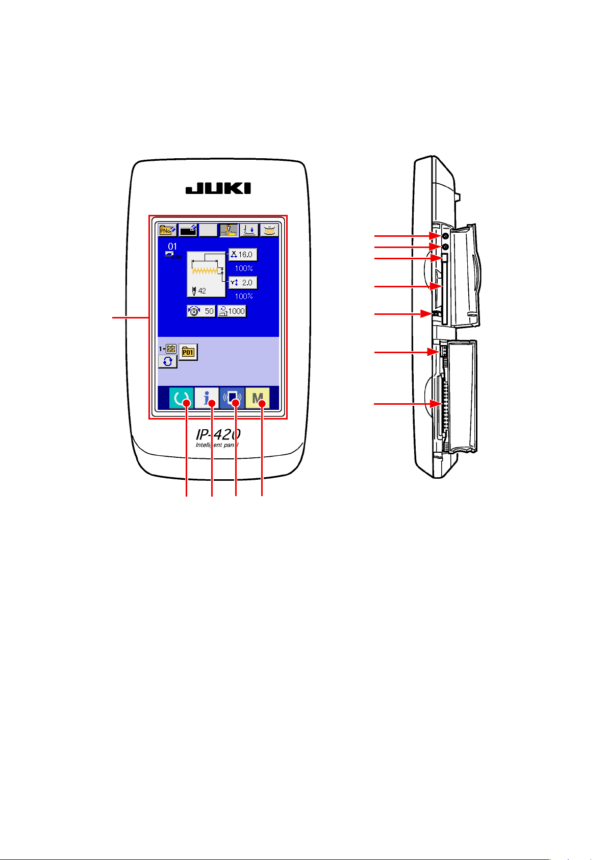
1. NAME OF EACH SECTION OF THE OPERATION PANEL
1-1 Body
(Front) (Right side)
⑥
⑦
⑧
⑨
①
②
③
⑩
⑪
⑫
④ ⑤
– 1 –
Page 6

Touch panel • LCD display section
①
②
③
④
⑤
Contrast control
⑥
Brightness control
⑦
READY key
INFORMATION key
COMMUNICATION key
MODE key
Changeover of the data input screen and the
→
sewing screen can be performed.
Changeover of the data input screen and the
→
information screen can be performed
Changeover of the data input screen and the
→
communication screen can be performed.
Changeover of the data input screen and the
→
mode changeover screen which performs various
detail settings can be performed.
CompactFlash (TM) eject button
⑧
CompactFlash (TM) slot
⑨
Cover detection switch
⑩
Connector for external switch
⑪
Connector for control-box connection
⑫
– 2 –
Page 7
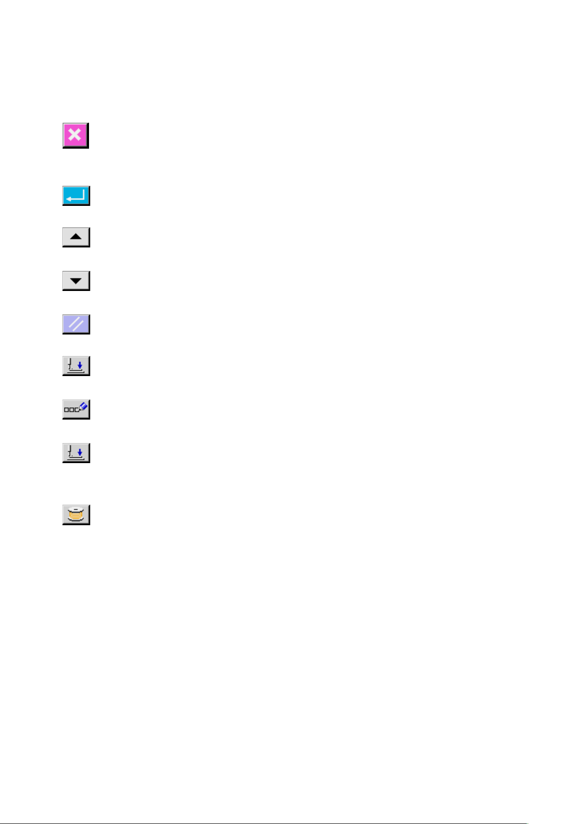
1-2 Buttons to be used in common
The buttons which perform common operations in each screen of IP-420 are as follows :
CANCEL button
ENTER button
UP SCROLL button
DOWN SCROLL button
RESET button
NUMERAL INPUT button
CHARACTER INPUT but-
This button closes the pop-up screen.
→
In case of the data change screen, the data being changed can
be cancelled.
This button determines the changed data.
→
This button scrolls the button or the display in the upward direc-
→
tion.
This button scrolls the button or the display in the downward
→
direction.
This button performs the release of error.
→
This button displays ten keys and input of numerals can be per-
→
formed.
This button displays the character input screen.
→
ton
PRESSER DOWN button
BOBBIN WINDER button
Refer to
→
This button lowers the presser and displays the presser down screen.
→
To raise the presser, press PRESSER UP button displayed in the
presser down screen.
This button performs bobbin thread winding.
→
Refer to
→
“18. NAMING PATTERN” p.46
“11. WINDING BOBBIN THREAD” p.29
.
.
– 3 –
Page 8

2. BASIC OPERATION OF IP-420
LK-1900B is explained as the standard in this In-
struction Manual.
Turn ON the power switch
①
When the power is turned ON first, the selection
screen of the language is displayed. Set the lan-
guage used. (It is possible to change with memory
switch
Select the pattern No. you desire to sew.
②
When the power is turned ON , the data input
.)
When ending the selection screen with
CANCEL button or ENTER button
without selecting the language, the selec-
tion screen of the language is again dis-
played when turning ON the power next.
screen is displayed. The shape which is selected
at present in the center of the screen is displayed
on SHAPE SELECTION button A and the
selection of the sewing shape can be performed
when pressing the button. For selecting procedure
of the sewing shape, refer to
SEWING SHAPE SELECTION” p.11
For the pattern No., refer to the sewing
shape list.
“4. PERFORMING
.
A
When READY key B is pressed, the back color
of LCD display is changed to green, and the sewing
machine is set to the sewing possible state.
When the presser is raised, be careful
that ngers are notcaught in the presser
since the presser moves after havin-
glowered.
When turning OFF the power without
pressing READY key, the setting of "Pat-
tern No . " , "XY scale" and "number of
max. rotation" are not memorized.
Start sewing.
③
Set the sewing product to the presser portion, and
operate the pedal to start the sewing machine,
and sewing starts.
* For the screen, refer to
“3. LCD DISPLAY SEC-
TION AT THE TIME OF SEWING SHAPE SE-
LECTION” p.5 .
B
– 4 –
Page 9
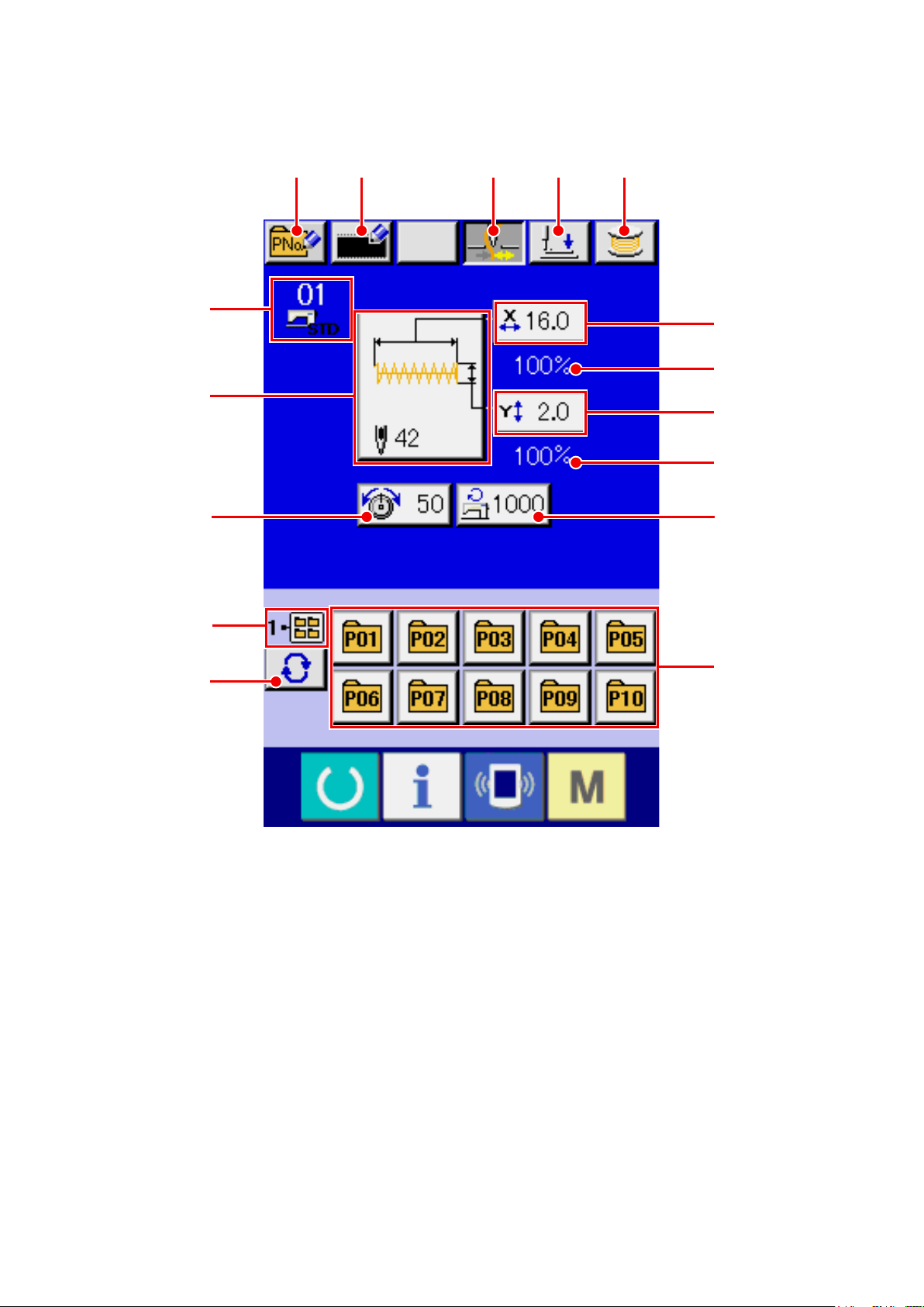
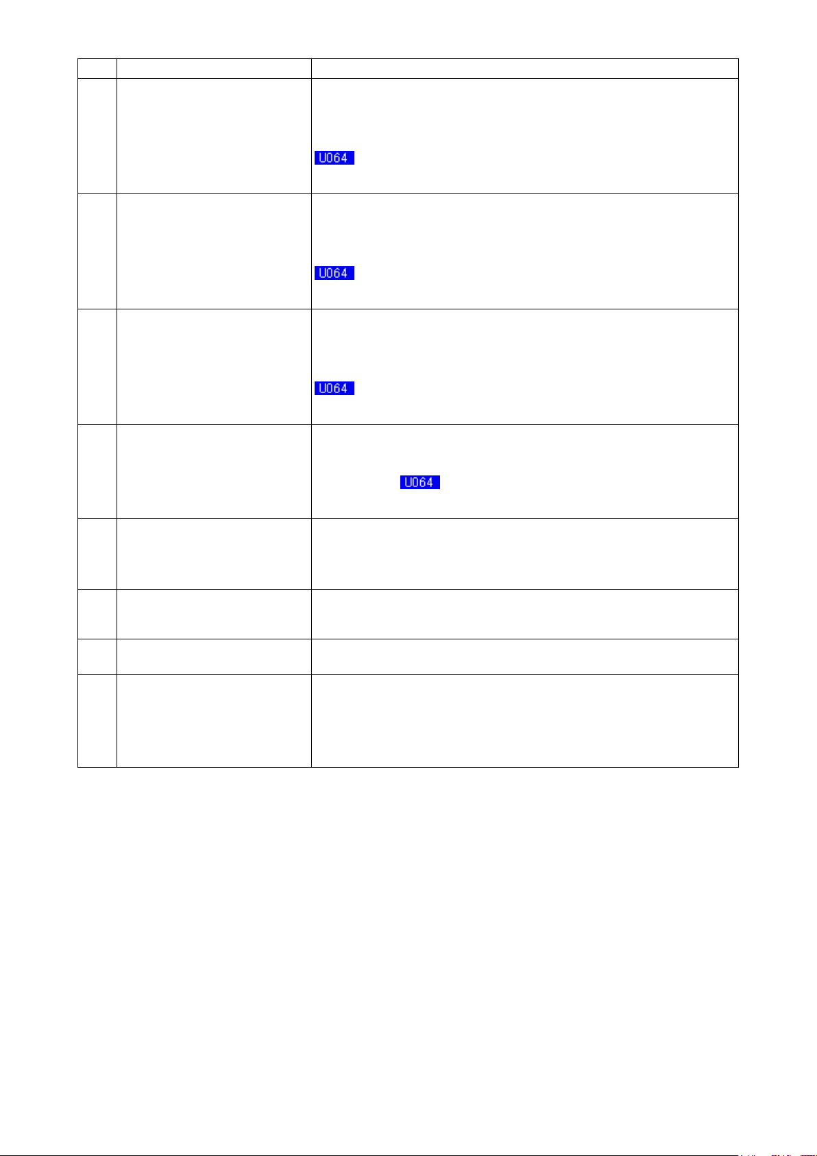
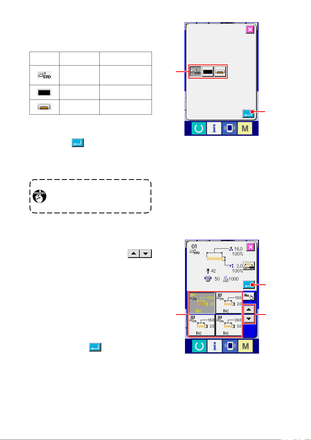
3. LCD DISPLAY SECTION AT THE TIME OF SEWING SHAPE SELECTION
3-1 Sewing shape data input screen
A B C D E
F
G
H
N
O
J
I
L
K
M
P
– 5 –
Page 10
Button and display Description
PATTERN BUTTON NEW REG-
A
ISTER button
USERS' PATTERN NEW REGIS-
B
TER button
THREAD CLAMP button Effective/ineffective of thread clamp is selected.
C
PRESSER DOWN button Presser can be lowered and the presser down screen is displayed.
D
BOBBIN WINDER button Bobbin thread can be wound.
E
Pattern button new register screen is displayed.
Refer to
→
p.35
Users' pattern new register screen is displayed.
Refer to
→
p.34
* When the prohibition of thread clamp is set with memory switch ,
the thread clamp button is not displayed.
To raise the presser, press the presser up button which is displayed in the
presser down screen.
Refer to
→
“14. PERFORMING NEW REGISTER OF PATTERN BUTTON”
.
“13. PERFORMING NEW REGISTER OF USERS’ PATTERN”
.
: Thread clamp ineffective
: Thread clamp effective
“11. WINDING BOBBIN THREAD” p.29
.
SEWING SHAPE No. display Kind and No. of the sewing shape being selected at present are displayed.
F
There are three kinds of sewing shapes below.
: Standard pattern
: Media pattern
: Users' pattern
SEWING SHAPE SELECTION
G
button
NEEDLE THREAD TENSION
H
SETTING button
Sewing shape being selected at present is displayed on this button and
when the button is pressed, the sewing shape selection screen is displayed.
Refer to
→
Needle thread tension value which is set to the pattern data being selected
at present is displayed on this button and when the button is pressed, the
item data change screen is displayed.
Refer to
→
“4. PERFORMING SEWING SHAPE SELECTION” p.11
“6. PERFORMING ITEM DATA CHANGE” p.17
.
.
– 6 –
Page 11
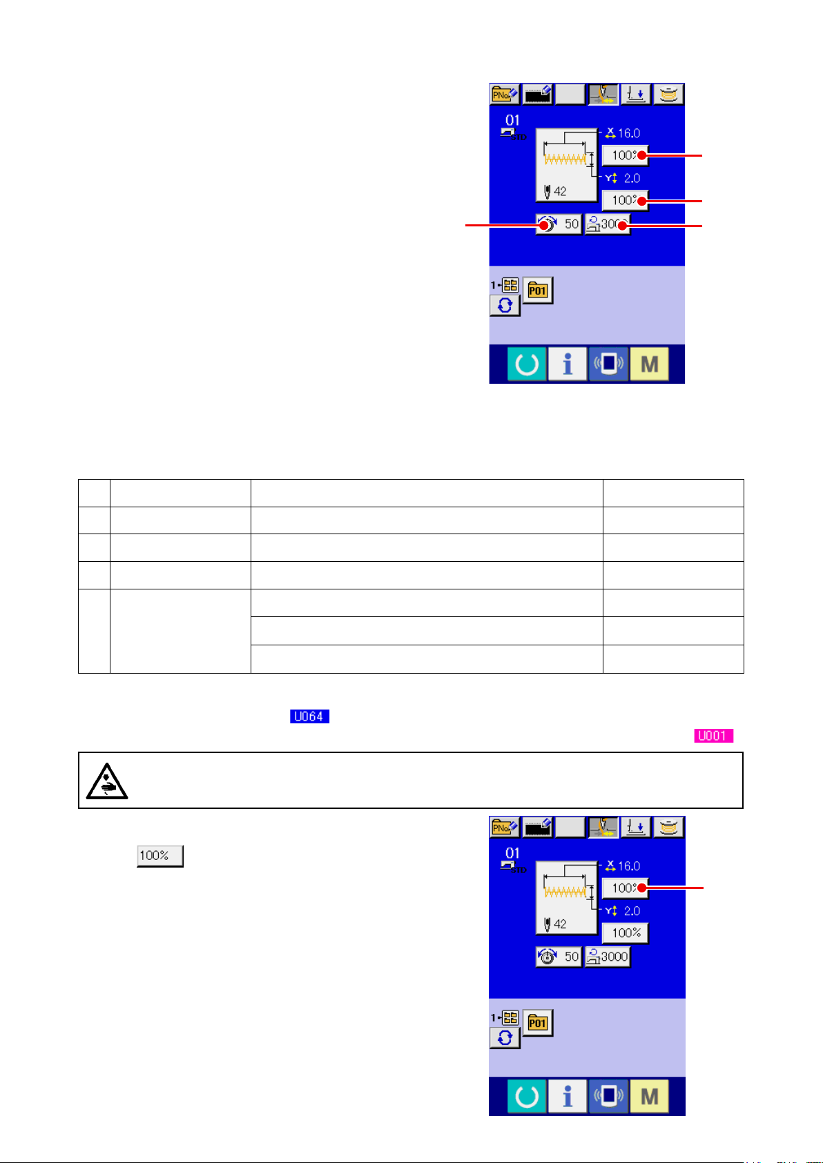
Button and display Description
X ACTUAL SIZE VALUE display Actual size value in X direction of sewing shape being selected at present is
I
displayed.
When the actual size value input is selected by setting memory switch
, X actual size value setting button is displayed.
Refer to
→
X SCALE RATE SETTING button Scale rate in X direction of sewing shape being selected at present is dis-
J
played on this button.
When the scale input is set to non-selection by setting memory switch
Refer to
→
Y ACTUAL SIZE VALUE display Actual size value in Y direction of sewing shape being selected at present is
K
displayed.
When the actual size value input is selected by setting memory switch
Refer to
→
Y SCALE RATE SETTING button Scale rate in Y direction of sewing shape being selected at present is dis-
L
played on this button. When the scale input is set to non-selection by setting
memory switch , the button goes out and the Y scale is displayed.
Refer to
→
“6. PERFORMING ITEM DATA CHANGE” p.17
, the button goes out and the X scale is displayed.
“6. PERFORMING ITEM DATA CHANGE” p.17
, Y actual size value setting button is displayed.
“6. PERFORMING ITEM DATA CHANGE” p.17
“6. PERFORMING ITEM DATA CHANGE” p.17
.
.
.
.
MAX. SPEED LIMITATION Maximum speed limitation which is set at present is displayed on this button
M
and when the button is pressed, the item data change screen is displayed.
Refer to
→
FOLDER No. display Pattern register button which is displayed indicates the folder No. which has
N
been stored.
FOLDER SELECTION button Folders to display the patterns are displayed in order.
O
PATTERN REGISTER button PATTERN REGISTER buttons stored in N FOLDER No. display are dis-
P
played.
Refer to
→
p.35
“6. PERFORMING ITEM DATA CHANGE” p.17
“14. PERFORMING NEW REGISTER OF PATTERN BUTTON”
.
.
– 7 –
Page 12
3-2 Sewing screen
F
G
H
I
J
K
L
E D
A
B C
N
O
P
Q
M
R
– 8 –
Page 13
Button and display Description
THREAD CLAMP button Effective/ineffective of the thread clamp is selected.
A
: Thread clamp ineffective
: Thread clamp effective
* When the prohibition of thread clamp is set with memory switch ,
the thread clamp button is not displayed.
PRESSER DOWN button Presser can be lowered and the presser down screen is displayed.
B
To raise the presser, press the presser up button which is displayed in the
presser down screen.
RETURN TO ORIGIN button This button returns the presser to the start of sewing and raises the presser.
C
X ACTUAL SIZE VALUE display Actual size value in X direction of sewing shape being selected is displayed.
D
X SCALE RATE display Scale rate in X direction of sewing shape being selected is displayed.
E
SEWING SHAPE No. display Kind and No. of sewing shape being selected at present are displayed.
F
There are three kinds of sewing shapes below.
: Standard pattern
: Media pattern
: Users' pattern
SEWING SHAPE display Sewing shape being selected at present is displayed.
G
SEWING SHAPE Total number of
H
stitches display
NEEDLE THREAD TENSION
I
SETTING button
COUNTER VALUE CHANGE
J
button
COUNTER CHANGE OVER but-
K
ton
Total number of stitches of the sewing shape being selected at present is
displayed.
Needle thread tension value which is set to the pattern data being selected
at present is displayed on this button and when the button is pressed, the
item data change screen is displayed.
Refer to
→
Existing counter value is displayed on this button. When the button is
pressed, the counter value change screen is displayed.
Refer to
→
Display of sewing counter/No. of pcs. counter can be changed over.
Refer to
→
“6. PERFORMING ITEM DATA CHANGE” p.17
“12. USING COUNTER” p.30
“12. USING COUNTER” p.30
.
.
.
– 9 –
Page 14

Button and display Description
STEP SEWING button Display of sewing counter/No. of pcs. counter can be changed over.
L
Refer to
→
FOLDER No. display Pattern register button which is displayed indicates the folder No. which has
M
been stored.
SPEED variable resistor Number of rotations of the sewing machine can be changed.
N
Y ACTUAL SIZE VALUE display Actual size value in Y direction of sewing shape being selected is displayed.
O
Y SCALE RATE display Scale rate in Y direction of sewing shape being selected is displayed.
P
“7. CHECKING PATTERN SHAPE” p.19
.
MAX. SPEED LIMITATION dis-
Q
play
PATTERN REGISTER button Pattern register buttons stored in M FOLDER No. display are displayed.
R
Maximum speed limitation which is set at present is displayed.
Refer to
→
p.35
“14. PERFORMING NEW REGISTER OF PATTERN BUTTON”
.
– 10 –
Page 15
4. PERFORMING SEWING SHAPE SELECTION
Display the data input screen.
①
Only in case of the data input screen (blue), the
selection of sewing shape is possible. In case
of the sewing screen (green), press READY key
and display the data input screen (blue).
Call the sewing shape selection screen.
②
Press SEWING SHAPE button A and the
sewing shape selection screen is displayed.
Select the kind of sewing shape.
③
There are three different sewing shapes.
A
Press SEWING SHAPE SELECTION button
B.
B
– 11 –
Page 16
Determine the kind of sewing shape.
④
There are three kinds of sewing shapes below.
Select the kind you desire from among them.
Pictograph Name
Standard pattern
Users' pattern 200
Media pattern 999
Maximum number of
patterns
1900/1901/1902 : 51
1903 : 50
Select the sewing shape you desire from SEW-
ING SHAPE SELECTION buttons C and press
ENTER button D.
The sewing shape list screen corresponding to
the kind of sewing shape you selected is dis-
played.
Be sure to use the media that has been for-
matted with IP-420.
For the formatting procedure of the media,
refer to “26-3 Performing format” p.87 .
C
D
Select the sewing shape.
⑤
When UP or DOWN SCROLL button
is pressed, SEWING SHAPE buttons F are
E
changed over in order. The description of the
sewing shape is displayed in the button.Here,
press the SEWING SHAPE button you desire to
select. The details of the selected shape is dis-
played at the upper part of the screen.
Determine the sewing shape.
⑥
When ENTER button
is pressed, the
G
sewing shape is determined and the data input
screen is displayed.
F
G
E
– 12 –
Page 17
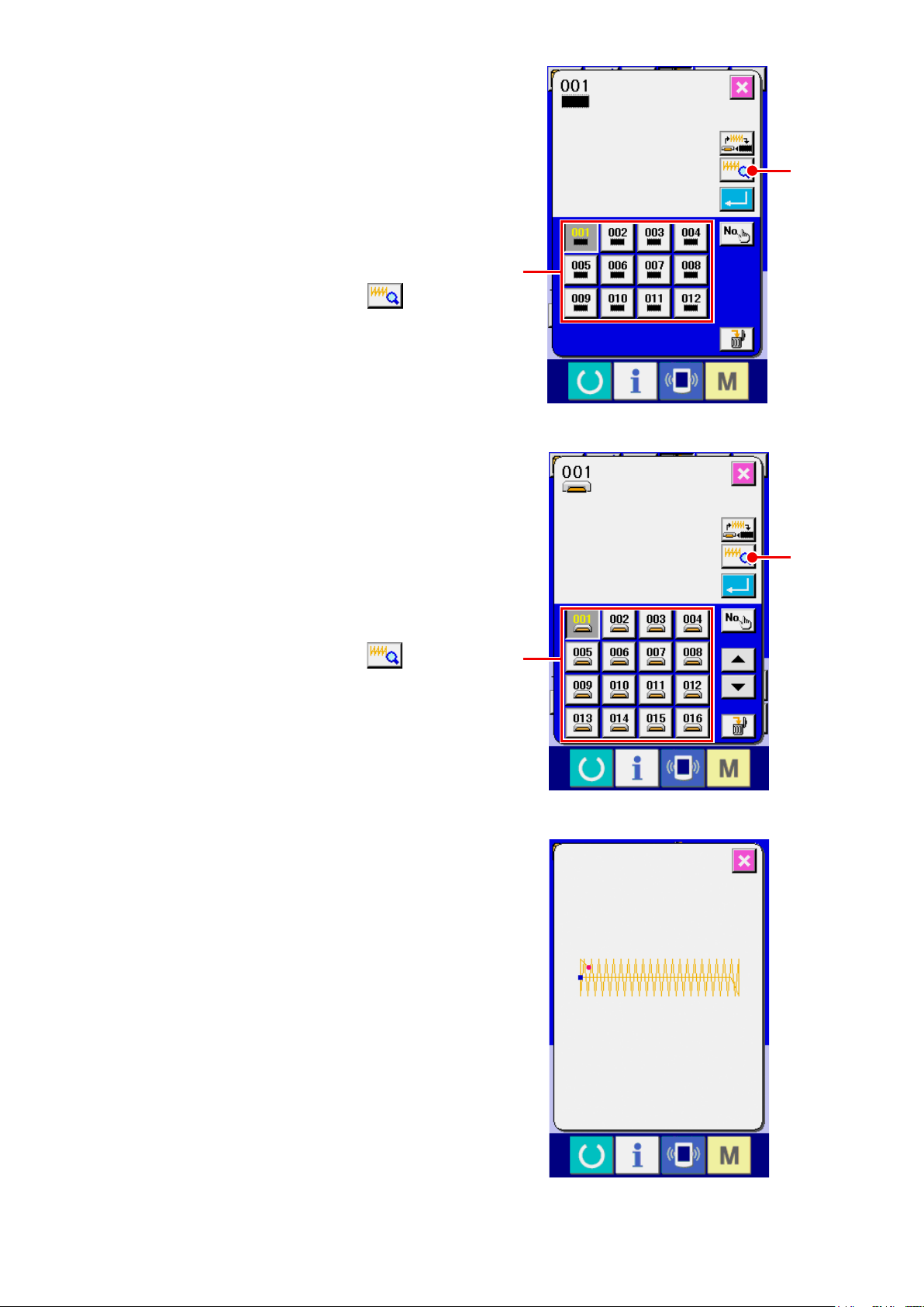
When the sewing shape is users' pattern or me-
dia pattern the screen as shown on the right side
is displayed.
PATTERN No. SELECTION buttons
have been registered to users' pattern or media
pattern are displayed. Press the button of the pat-
tern No. you desire to select.
In addition, when you desire to conrm the shape
you selected, press VIEWER button
Then the viewer screen is displayed and the se-
lected shape is displayed.
When the sewing shape is media pattern the
screen as shown on the right side is displayed.
PATTERN No. SELECTION buttons
have been registered to media pattern are dis-
played. Press the button of the pattern No. you
desire to select.
which
H
which
H
I
I
H
.
I
In addition, when you desire to conrm the shape
you selected, press VIEWER button
Then the viewer screen is displayed and the se-
lected shape is displayed.
I
.
H
– 13 –
Page 18
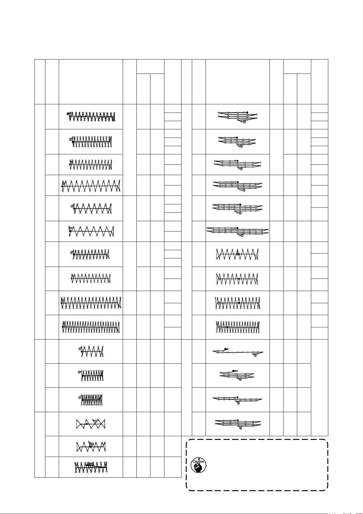
5. SEWING SHAPE LIST
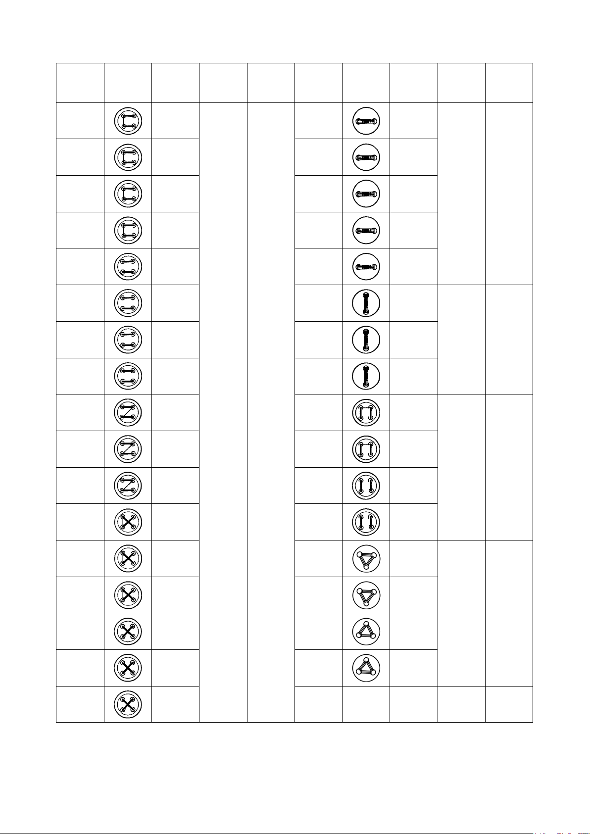
5-1 LK-1900B / LK-1901B / LK-1902B
Sewing
size (mm)
No Stitch diagram
presser
(Note 2) No. of
Crosswise
Lengthwise
Number of stitches
1
(51)
2 2.0 10 1 18 28 0 10 1
*3 2.5 16 1 19 0 25 6
*4 3.0 24 6 20 36 0 25 6
5 28 2.0 10 1 21 41 0 25 6
*6 2.5 16 1 22 44 0 35
Large bar-tackingSmall bar-tacking
7 36 2.0 10 1 23 28 20 4.0 9
*8 2.5 16 1 24 36 20 4.0 9
42 2.0 16 1 17 21 0 10 1
2 2
3 3
2 2
3 3
4 7
7 7
2
3
4
2
3
No Stitch diagram
Linear bar-tacking
(Other side)(Other side)(Other side)(Other side)(Other side)(Other side)(Other side)(Other side)
(This side)(This side)(This side)(This side)(This side)(This side)(This side)(This side)
Sewing
size (mm)
Lengthwise
Number of stitches
(Note 2) No. of
Crosswise
7
(Note
3)
10
presser
4 10
*9 56 3.0 24 6 25 42 20 4.0 9
7 10
*10 64 3.0 24 6 26 56 20 4.0 9
11 21 2.5 6 6 27 18 20 0 11
12 28 2.5 6 28 21 10 0
13 36 2.5 6 29 20 0
14 14 2.0 8 5 30 28 20 0
15 21 2.0 8
Lengthwise bar-tacking
7 10
Lengthwise linear bar-tacking
1. Sewing size shows the dimensions when
the scale rate is 100%.
16 28 2.0 8
Knit goods bar-tacking
2. Refer the No. of presser to the separate
table of presser.
3. For No. 22, process the presser blank for use.
4. Use the patterns with * marks for sewing denim.
5. No.51 is for the machine without tread clamp.
– 14 –
Page 19
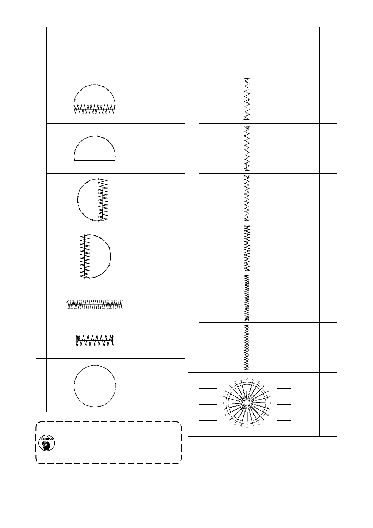
Sewing
size (mm)
Sewing
size (mm)
No Stitch diagram
Lengthwise
Number of stitches
31 52 7 10 13
32 63 7 12 13
33 24 6 10 13
34 31 6 12 13
35 48 10 7 14
Semilunar bar-tacking
36 48 10 7 14
(Note 2) No. of
Crosswise
presser
No Stitch diagram
Crosswise
Lengthwise
Number of stitches
41 29 20 2.5 12
42 39 25 2.5 12
43 45 25 2.5 12
44 58 25 2.5 12
presser
(Note 2) No. of
37 90 3 24 6
Large bartacking
38 28 2 8 5
Knit goods bartacking
39 28 Φ12 16
40 48
Round bar-tacking
Pattern Nos. 41 to 46 are for the optional
work clamp foot No. 12. They are different
from the lengthwise bar tacking pattern Nos.
23 to 26 in the origin by 5 mm up and down.
Lengthwise bar-tacking
45 75 30 2.5 12
7
46 42 30 2.5 12
47 91 Φ8 15
48 99
49 148
Radial tacking
50 164
– 15 –
Page 20
5-2 LK-1903B
Pattern
No.
1 - 34 6-6
2 - 35 8-8 19 - 45 8
3 10-10 20 10
4 12-12 21 12
5 - 36 6-6 22 16
6 - 37 8-8 23 - 46 6
Stitch
shape
Number of
threads
(thread)
Standard
sewing size
X (mm)
Standard
sewing size
Y (mm)
Pattern
No.
18 - 44 6
Stitch
shape
Number of
threads
(thread)
Standard
sewing size
X (mm)
3.4 0
0 3.47 10-10 24 10
Standard
sewing size
Y (mm)
8 12-12 25 12
9 - 38 6-6 26 - 47 6-6
10 - 39 8-8 27 10-10
11 10-10 28 - 48 6-6
12 - 40 6-6 29 10-10
13 - 41 8-8 30 - 49 5-5-5
14 10-10 31 8-8-8
15 - 42 6-6 32 - 50 5-5-5
3.4 3.4
3.4 3.4
3.0 2.5
16 - 43 8-8 33 8-8-8
17 10-10
* The standard sewing sizes of X and Y are when the enlargement/reduction rate is 100%.
Use pattern Nos. 34 to 50 when the button hole is small (φ1.5 mm or less).
* For the sewing machine provided with the bird's nest preventing and shorter-thread remaining type thread
trimmer, pattern numbers 23 to 25, 30 to 33, 46, 49 and 50 have been factory-set, at the time of delivery,
so that they are not displayed.
To use those pattern numbers, change the setting so that the memory switch K102 is displayed.
– 16 –
Page 21
6. PERFORMING ITEM DATA CHANGE
Display the data input screen.
①
In case of the data input screen, the change of
item data can be changed. In case of the sewing
A
screen (green), press READY key to display the
data input screen (blue).
C
B
D
* Thread tension value can be changed even in the
sewing screen.
Display the item data input screen.
②
When the button of the item data you desire to change is pressed, the item data input screen is displayed.
There are four items of the item data below.
Item Input range Initial value
Scale rate in X direction 20 to 200 (%) 100 (%)
A
Scale rate in Y direction 20 to 200 (%) 100 (%)
B
Thread tension 0 to 200 50
C
1900 : 400 to 3200 (sti/min) 3200 (sti/min)
Max. speed limitation
D
1903 and 1900 double-capacity hook : 400 to 2700 (sti/min) 2700 (sti/min)
1901 and 1902 : 400 to 3000 (sti/min) 3000 (sti/min)
* A Scale rate in X direction and B Scale rate in Y direction can be changed to actual size value input by
selection of the memory switch .
*
Max. inputting range of max.limitation speed D and the initial value are determined with memory switch .
CAUTION :
The setting exceeding 100% is dangerous since needle and the cloth presser interferes with each
other and needle breakage or the like will occur.
For example, input X scale rate.
Press A to display the item data input screen.
A
– 17 –
Page 22
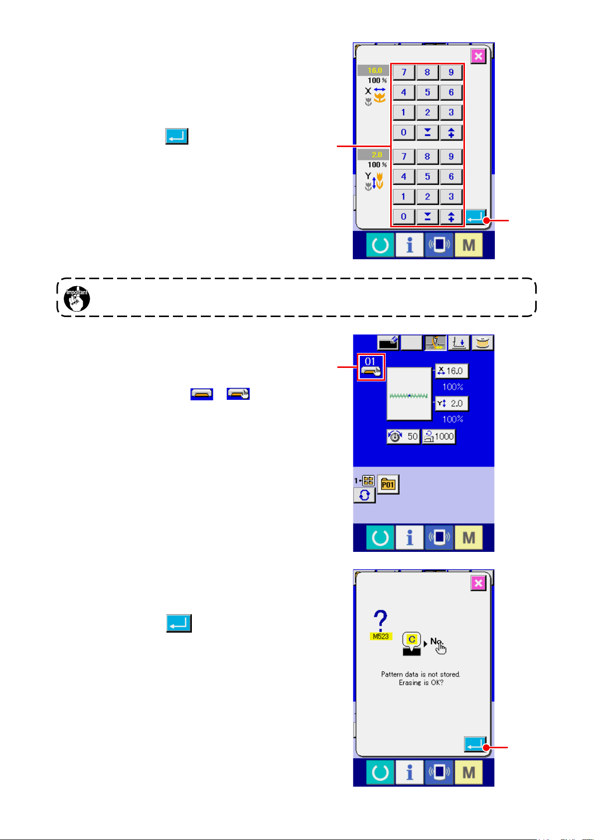
③ Input the data.
Input the value you desire with ten keys and +/-
keys E.
④ Determine the data.
When ENTER button F is pressed, the data
is determined.
* For the other item data, the data can be changed
by the same operation.
* X/Y scale or X/Y value of X/Y actual size value can
be inputted in one screen.
When turning OFF the power without pressing READY key, the set values of pattern No. , X/Y
scale, and number of max. rotation are not memorized.
E
F
In the case of adding or deleting the thread ten-
sion and the thread tension command for the pat-
terns stored on a medium, the pattern type section
display H will change from to
.
In case of change display H, the change con-
rmation screen is displayed at the time of the
change of pattern.
When ENTER button I is pressed, the
H
information on the current pattern is invalidated
and the pattern No. is changed.
To store the changed pattern, refer to
“13. PER-
FORMING NEW REGISTER OF USERS’ PAT-
TERN” p.34 .
I
– 18 –
Page 23
7. CHECKING PATTERN SHAPE
WARNING :
Make sure without fail of the contour of the sewing pattern after selection of the sewing pattern.
If the sewing pattern extends outside the work clamp feet, the needle will interfere with the work
clamp.
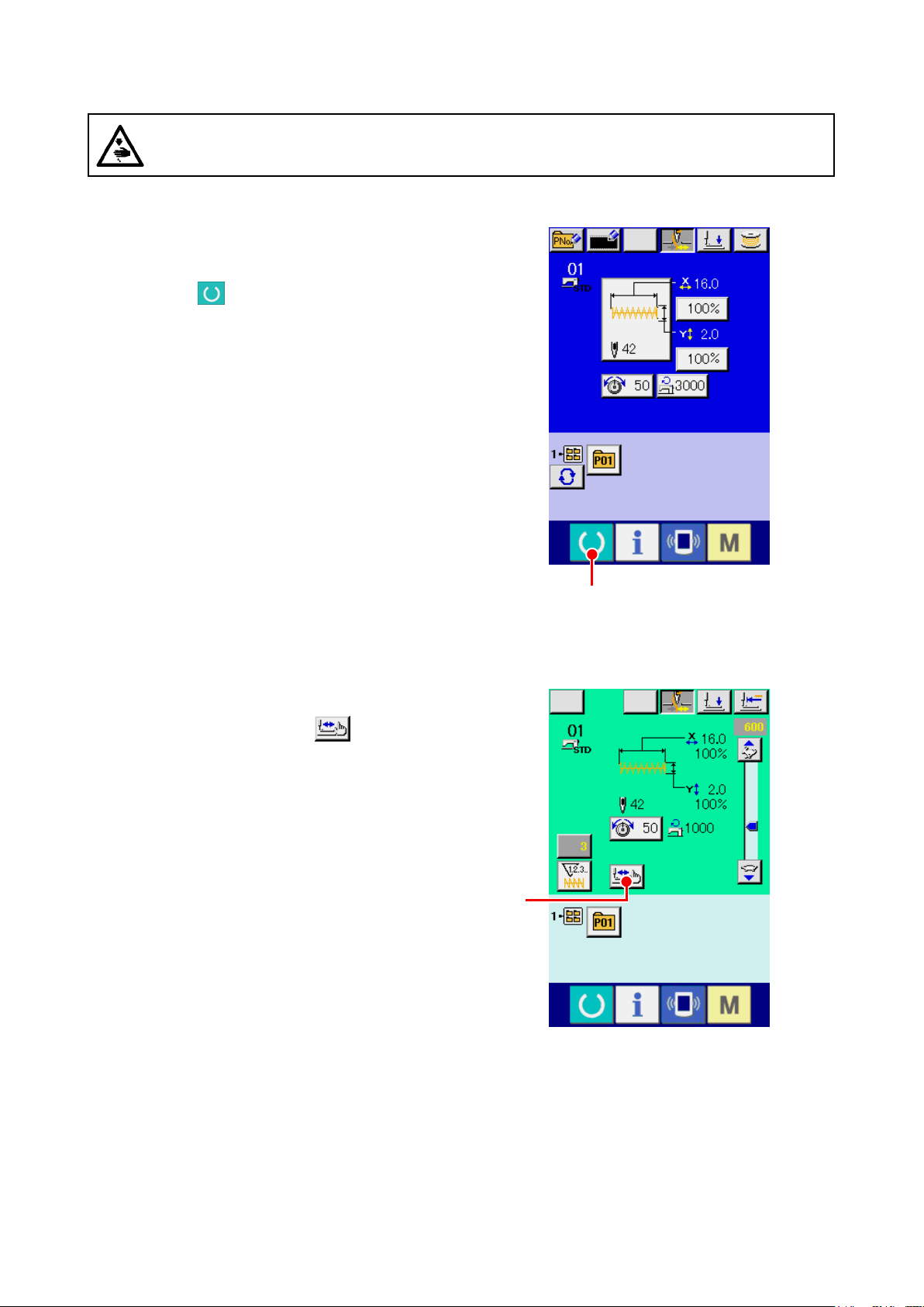
Display the sewing screen.
①
Display the data input screen (blue) and press
READY key A . Then the back-light of LCD
changes to green and sewing is possible.
Display the step sewing screen.
②
When STEP SEWING button B is pressed,
the step sewing screen is displayed.
A
B
– 19 –
Page 24
Lower the presser with the foot switch.
③
The work clamp feet do not go up even
when the foot switch is detached.
Proceed stitching with the presser lowered.
④
Check the shape with PRESSER BACK button
E
C and PRESSER FORWARD button
.
D
When holding pressing the button for a certain
C
D
F
G
time, the presser continues to move even when
the button is released.
When you desire to stop, press STOP button
G. When ORIGIN MOVE button F is
pressed, the machine moves to the origin and the
screen returns to the sewing screen.
When pressing the presser forward or presser backward button with the needle bar lowered,
the presser moves after automatically returning the needle bar to UP position. So, be careful.
Finish checking the shape.
⑤
When CANCEL button E is pressed, the screen returns to the sewing screen.
When the presser is not in the sewing start position or the sewing end position, press the foot switch.
Then it is possible to sew from the midway of checking.
– 20 –
Page 25
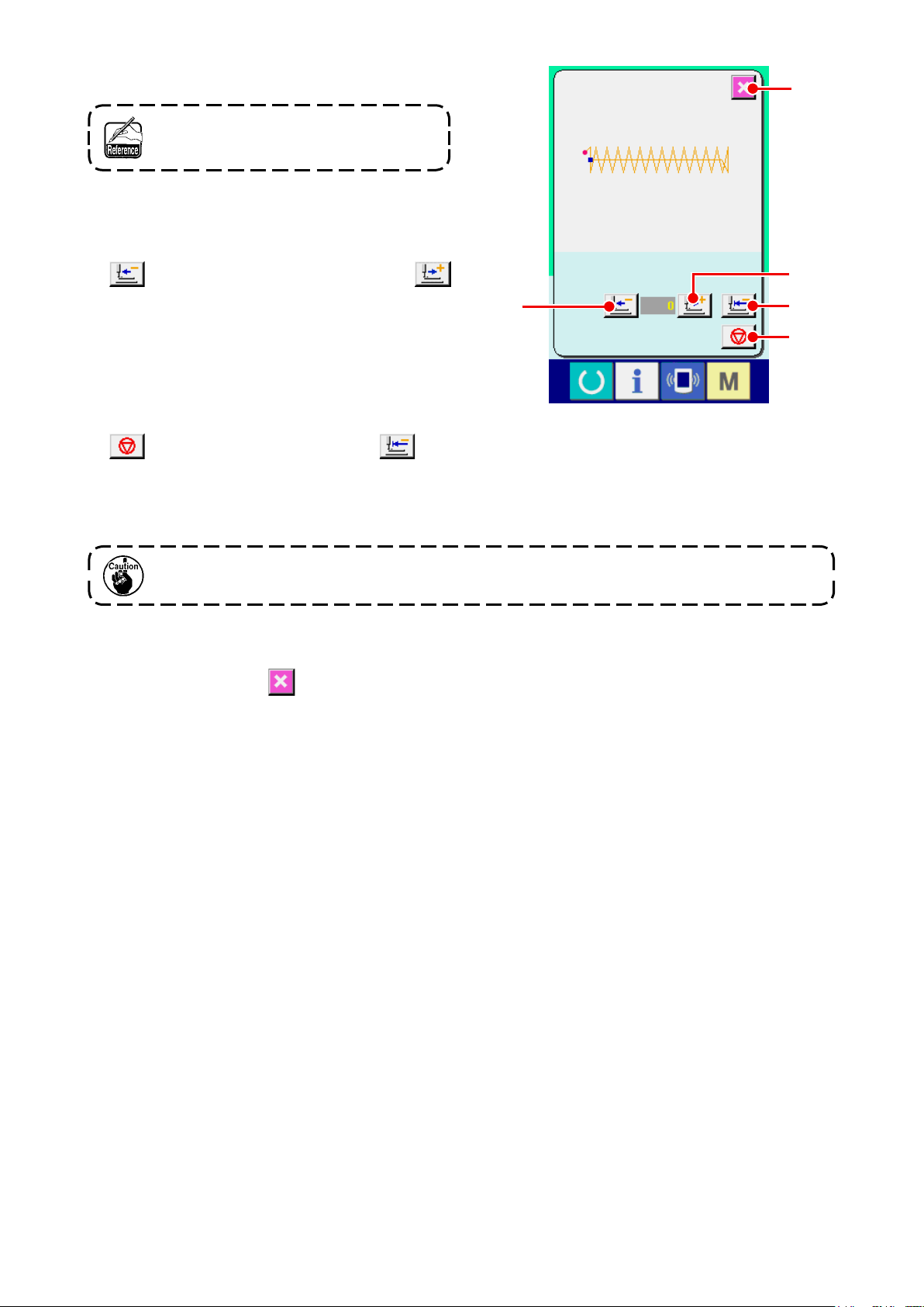
8. CHANGING THREAD TENSION COMMAND AT EVERY NEEDLE ENTRY POINT
8-1 Adding or changing thread tension command at every needle entry point
Display the thread tension command change screen
①
When selecting a standard pattern, user pattern
or a pattern stored on a medium, press thread
tension button A on the sewing screen to
display the thread tension setting screen. Press
THREAD TENSION COMMAND CHANGE button
B on the thread tension setting screen and
the thread tension command change screen is
displayed.
The sewing machine does not start even
when the foot switch is depressed under
this mode.
② Specify the command position you desire to
change.
Specify the position you desire to add the thread
tension command or that you desire to change the
A
thread tension command value with ONE STITCH
BACKWARD button C or ONE STITCH
FORWARD button D in the state that the
presser is lowered.
In addition, the machine moves to the needle entry
point where the front or rear thread tension com-
mand exists with E or F. When you
desire to stop the move, press STOP button
G.
When ORIGIN MOVE button H is pressed,
the machine moves to the origin.
The value to be displayed is the absolute value
(thread tension value + thread tension command
value).
C
E
B
D
H
– 21 –
F G
Page 26
Input thread tension command value.
③
When COMMAND INPUT button
pressed, the thread tension increase/decrease
value input screen is displayed. Input the value
you desire with TEN keys and +/- keys J. When
ENTER button K is pressed, the data is de-
termined.
* For the standard patterns, the thread tension
command entry button is displayed only at the po-
sition where the thread tension command already
exists.
I
is
I
J
K
– 22 –
Page 27
8-2 Deleting thread tension command at every needle entry point
① Display the thread tension command change
screen.
When selecting a standard pattern, user pattern
or a pattern stored on a medium, press thread ten-
sion button A on the sewing screen to
display the thread tension setting screen.
When THREAD TENSION COMMAND CHANGE
button B on the thread tensionsetting screen
is pressed, the thread tension command change
screen is displayed.
A
B
– 23 –
Page 28
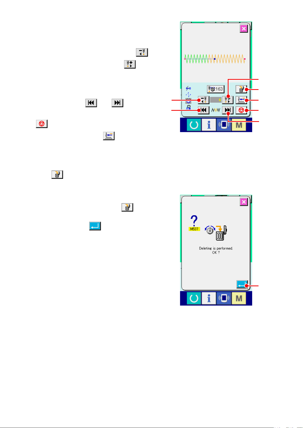
Designate the command position desired to
②
be deleted.
Specify the command position you desire to de-
lete with ONE STITCH BACKWARD button
or ONE STITCH FORWARD button D in
C
the state that the presser is lowered.
In addition, the machine moves to the needle
entry point where the front or rear thread tension
command exists with E or F. When
you desire to stop the move, press STOP button
G.
When ORIGIN MOVE button H is pressed,
the machine moves to the origin.
When the present needle entry point exists on the
thread tension command, COMMAND DELETE
button L is displayed.
③ Delete the thread tension command.
When COMMAND DELETE button L is
pressed, the command delete screen is displayed.
C
E
D
L
H
G
F
When ENTER button M is pressed, the
command is deleted.
* For the standard patterns, the thread tension
command cannot be deleted.
M
– 24 –
Page 29
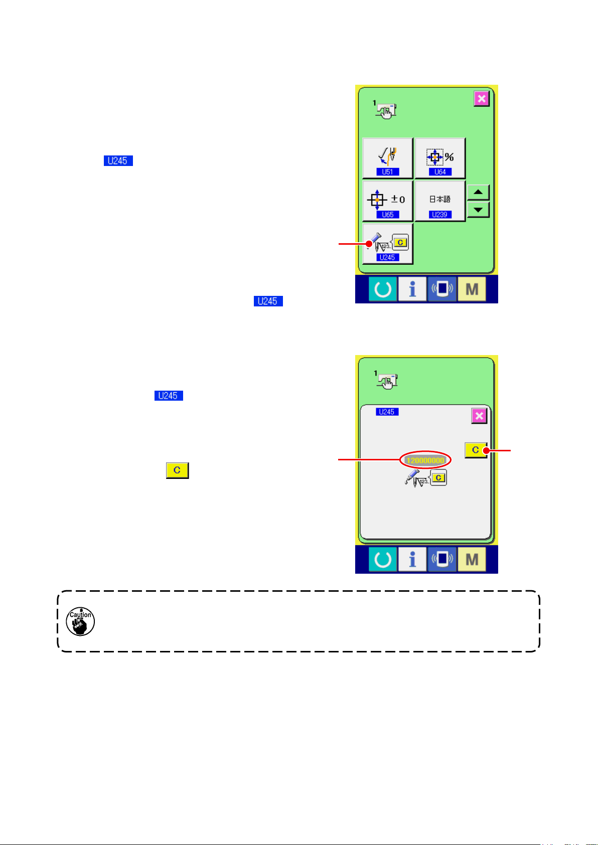
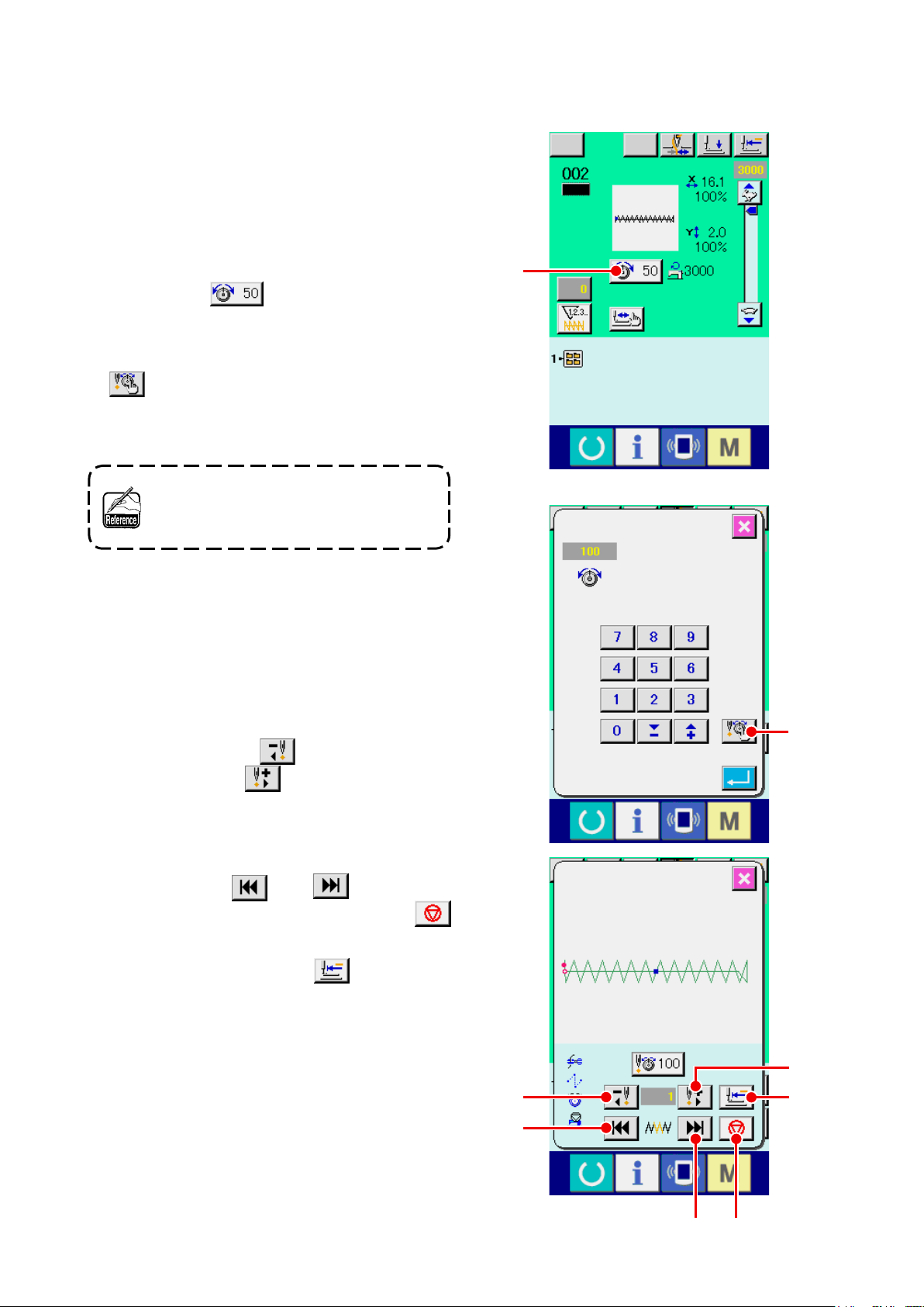
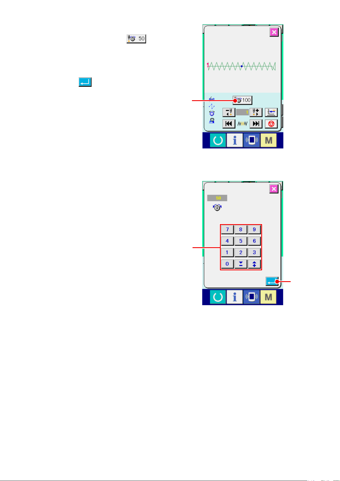
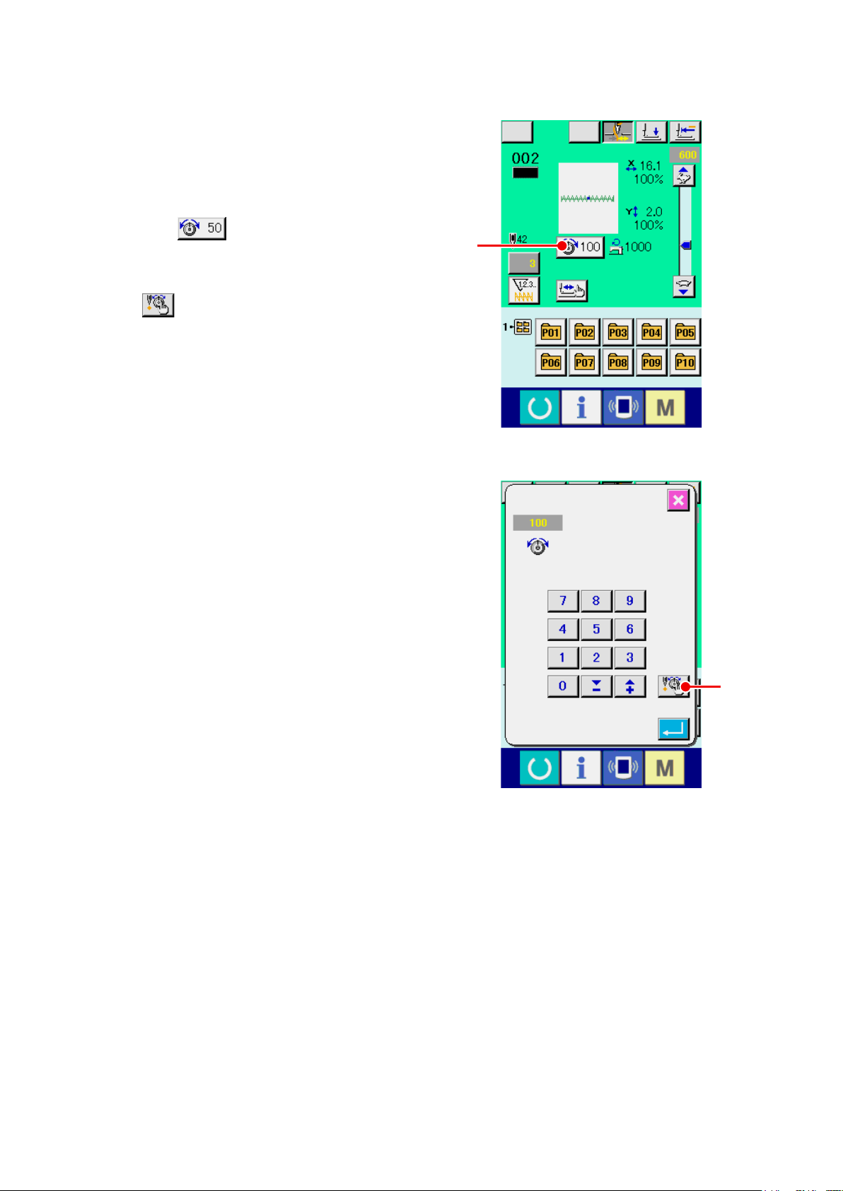
9. PERFORMING RELEASE OF GREASE-UP ERROR
When the number of stitches of grease-up exceeds
100 million stitches or more, E220, grease-up warn-
ing occurs when turning ON the power.
Clear the number of stitches of grease-up with mem-
ory switch , grease-up error clear
after replenishing grease. E220 is displayed each
time turning ON the power until clearing is per-
formed.
When the number of stitches of grease-up exceeds
120 million stitches or more, E221, grease-up error
occurs when READY key is pressed. When E221
occurs, it is not possible to sew. Clear the number
of stitches of grease-up with memory switch ,
grease-up error clear after replenishing grease
A
Display the memory switch data list screen.
①
Display the memory switch data list screen and
select button A of Grease-up error clear.
The grease-up error clear screen is displayed.
② Clear the number of stitches of grease-up.
When CLEAR button B is pressed, the pop-
up is closed and the number of stitches of grease-
up can be cleared.
1. Error code E220 or E221 is displayed again unless UMBER OF STITCHES C is changed to "0"
after replenishing the designated places with grease. When E221 is displayed, the sewing machine fails to operate. So, be careful.
2. Be sure to turn the power OFF before applying grease.
C
B
– 25 –
Page 30
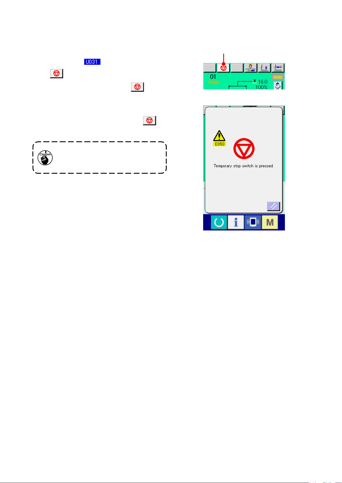
10. USING TEMPORARY STOP
When the panel temporary stop button is selected
with memory switch , TEMPORARY STOP
button A is displayed on the sewing screen.
When the TEMPORARY STOP button A is
pressed during sewing, the sewing machine can be
stopped. At this time, the error screen is displayed to
inform that the TEMPORARY STOP button A
is pressed.
Perform the same operation when the
external switch is used for the tempo-
rary stop.
A
– 26 –
Page 31

10-1 To continue performing sewing from some point in sewing
Release the error.
①
Press RESET button B to release the error.
B
Perform thread trimming.
②
Press THREAD TRIM button C to perform
When thread trimming has been performed,
FEED BACK button D ,FEED FORWARD
button E and RETERN TO ORIGIN button
F are displayed on the screen.
Adjust the presser to the re-sewing position.
③
When FEED BACK button D is pressed,
the presser returns stitch and by stitch and when
C
FEED FORWARD button E is pressed, it
advances stitch by stitch. Move the presser to the
re-sewing position.
Re-start the sewing
④
When the pedal is depressed, sewing starts
again.
– 27 –
D
E
F
Page 32

10-2 To perform re-sewing from the start
Release the error.
①
Press RESET button B to release the error.
B
Perform thread trimming.
②
Press THREAD TRIM button C to perform
thread trimming.
When thread trimming is performed, FEED BACK
button D , FEED FORWARD button
and RETURN TO ORIGIN button F are
E
displayed on the screen.
Return to the origin.
③
When RETURN TO ORIGIN button
pressed, the pop-up is closed, the sewing screen
F
is
C
is displayed and the machine returns to the posi-
tion of the start of sewing.
Perform again the sewing work from the start
④
When the pedal is depressed, sewing starts
again.
– 28 –
D
E
F
Page 33

11. WINDING BOBBIN THREAD
Pass the thread to wind bobbin thread as shown in
the gure on the right side.
Display the bobbin winding screen.
①
Press BOBBIN WINDER button A in the
data input screen (blue) and the bobbin winding
screen is displayed.
Start bobbin winding.
②
Depress the start pedal, and the sewing machine
rotates and starts winding bobbin thread.
Stop the sewing machine.
③
Press STOP button B and the sewing ma-
chine stops and returns to the normal mode. Or,
depress the start pedal again during winding bob-
bin and the sewing machine stops while the bob-
bin thread winding mode stays as it is. Depress
the start pedal again and the bobbin winding
starts again. Use this way when winding bobbin
thread around plural bobbins.
A
B
Bobbin winder does not work imme-
diately after turning ON the power or
moving from the main unit input.
Perform the bobbin winding after setting
pattern No. or the like, pressing READY
key , and making the sewing
screen display.
– 29 –
Page 34

12. USING COUNTER
12-1 Setting procedure of the counter
Display the counter setting screen.
①
When key is pressed in the data input
screen, COUNTER SETTING button
is displayed. When this button is pressed, the
counter setting screen is displayed.
A
A
Selection of kinds of counters
②
This sewing machine has three different counters;
i.e., the sewing counter, No. of pcs. counter and
bobbin counter. When SEWING COUNTER TYPE
SELECT button B, NO. OF PCS. COUNT-
ER TYPE SELECT button C or BOBBIN
COUNTER TYPE SELECT button
pressed, the corresponding counter type select
screen is displayed. On this screen, the counter
type can be selected individually.
D
B
C
D
is
– 30 –
Page 35

[ Sewing counter ]
UP counter :
Every time the sewing of one shape is performed, the existing
value is counted up. When the existing value is equal to the set
value, the count-up screen is displayed.
DOWN counter :
Every time the sewing of one shape is performed, the existing
value is counted down. When the existing value is reached to “0”,
the count-up screen is displayed.
Counter disuse:
The sewing counter does not count a nished shape even when
the machine has sewn the shape. The counter screen of the
sewing counter is not displayed.
[ No. of pcs. Counter ]
UP counter :
Every time one combination sewing is performed, the existing
value is counted up. When the existing value is equal to the set
value, the count-up screen is displayed.
DOWN counter :
Every time one combination sewing is performed, the existing
value is counted down. When the existing value is reached to “0”,
the count-up screen is displayed.
Counter disuse:
The No. of pcs. counter does not perform counting. The counter
screen of the No. of pcs. counter is not displayed.
[ Bobbin counter ]
UP counter :
The counter increases the existing value by one every time the
machine has sewn 10 stitches. When the existing value is equal
to the set value, the count-up screen is displayed.
DOWN counter :
The counter decreases from the existing value by one every time
the machine has sewn 10 stitches. When the existing value is
reached to “0”, the count-up screen is displayed.
Counter disuse:
The bobbin counter does not perform counting. The counter
screen of the bobbin counter is not displayed.
– 31 –
Page 36

Change of counter set value
③
E
F
G
Press button
E
for the sewing counter, button
for the No. of pcs. counter or button
F
for the bobbin counter to display the corresponding counter set value input screen.
Here, input the set value.
When “0” is inputted in the set value, the display of count-up screen is not performed.
Change of counter existing value
④
H
I
J
G
Press button
for the bobbin counter to display the corresponding counter current value input screen.
J
Here, input the existing value.
H
for the sewing counter, button
– 32 –
for the No. of pcs. counter or button
I
Page 37

12-2 Count-up releasing procedure
When the count-up condition is reached during sew-
ing work, the count-up screen is displayed and the
buzzer beeps. Press CLEAR button H to reset
the counter and the screen returns to the sewing
screen. Then the counter starts counting again.
12-3 How to change the counter value during sewing
Display the counter value change screen.
①
H
When you desire to revise the counter value
during sewing work due to the mistake or the like,
press COUNTER VALUE CHANGE button
on the sewing screen. The counter value
I
change screen is displayed.
Change the counter value.
②
Input the value you desire with ten keys, or + or -
key J.
I
Determine the counter value.
③
When ENTER button
data is determined.
When you desire to clear the counter value, press
CLEAR button K.
is pressed, the
L
– 33 –
K
J
L
Page 38

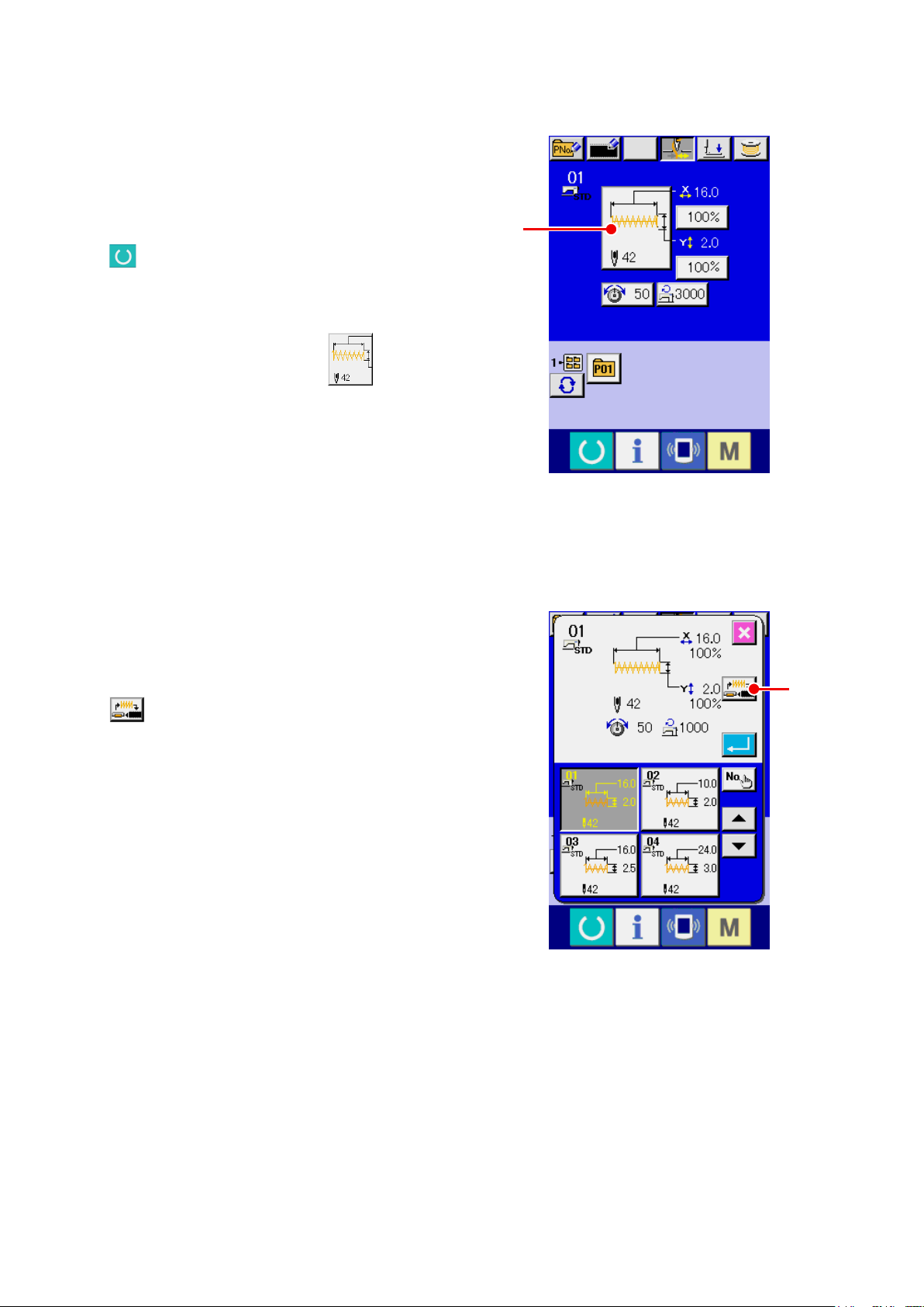
13. PERFORMING NEW REGISTER OF USERS' PATTERN
A
Display the data input screen.
①
Only in case of the data input screen (blue), new
register of the pattern can be performed. In case
of the sewing screen (green), press READY key
to display the data input screen (blue).
Call the new register of users' pattern screen.
②
Press NEW REGISTER button A and the
new register of users' pattern screen is displayed.
Input the users' pattern No.
③
Input the users' pattern No. you desire to newly
register with the ten keys B . When the users’
pattern No. which has been already registered is
inputted, press ENTER button E and E403
is displayed, Then select the users’ pattern No.
which has not been registered. New register to
the users' pattern No. which has been already
registered is prohibited.
It is possible to retrieve the users' pattern No.
which has not been registered with the + or - but-
ton (C and D ).
Determine the users' pattern No.
④
Press ENTER button E to determine the
users' pattern No. to be newly registered and the
E
B
D C
data input screen at the time of users' pattern se-
lection is displayed.
– 34 –
Page 39

14. PERFORMING NEW REGISTER OF PATTERN BUTTON
A
Display the data input screen.
①
Only in case of the data input screen (blue), new
register of the pattern button can be performed. In
case of the sewing screen (green), press READY
key to display the data input screen (blue).
Call the new register of pattern button screen.
②
Press NEW REGISTER button A and the
new register of pattern button screen is displayed.
Input the pattern button No.
③
Input the pattern button No. you desire to newly
register with the ten keys B. When the pattern
No. which has been already registered is in-
putted, the sewing shape which has been already
registered is displayed in the upper part of the
screen. Select the pattern button No. which is
not displayed and has not been registered. New
register to the pattern button No. which has been
already registered is prohibited.
It is possible to retrieve the pattern button No.
which has not been registered with the + or - but-
E
B
F
ton (C and D).
Select the folder to be stored.
④
It is possible for the pattern buttons to be stored
in one of the ve folders. As many as 10 pattern
buttons can be stored for one folder.
The folder to store the button can be selected
with FOLDER SELECTION button E. The folder
in which 10 pattern buttons have been stored is
not displayed.
Determine the pattern No.
⑤
Press ENTER button F to determine the pattern button No. to be newly registered and the data in-
put screen at the time of pattern button selection is displayed.
* When registering the users’ pattern to the pattern button, the comment registered to the users’ pattern is
not copied.
When the sewing screen is displayed and pressing P1 to P50 keys, the presser comes down.
Be careful not to allow the ngers to be caught in it.
D C
– 35 –
Page 40

15. LCD DISPLAY SECTION AT THE TIME OF PATTERN BUTTON
SELECTION
15-1 Pattern button data input screen
F
G
H
I
J
K
L
A B C D
E
M
N
O
P
Q
R
S
T
U
V
– 36 –
Page 41

Button and display Description
PATTERN BUTTON COPY button Pattern button copy screen is displayed.
A
Refer to
→
“19. COPYING PATTERN BUTTON” p.47
.
PATTERN BUTTON NAME SET-
B
TING button
PATTERN BUTTON NAME dis-
C
play
PRESSER DOWN button Presser can be lowered and the presser down screen is displayed.
D
WINDING BOBBIN button Bobbin thread can be wound.
E
PATTERN BUTTON No. display Pattern button No. being selected at present is displayed on this button and
F
SEWING SHAPE Sewing shape which is registered to the pattern button No. being selected is
G
SEWING SHAPE No. Kind of shape and sewing shape No. of the sewing shape which is registered
H
Pattern button name input screen is displayed.
Refer to
→
Character which is registered to the pattern button No. being selected is
displayed.
To raise the presser, press the presser up button displayed in the presser
down screen.
Refer to
→
when the button is pressed, the pattern button No. selection screen is dis-
played.
Refer to
→
p.42
displayed.
to the pattern button No. being selected are displayed.
There are three kinds of sewing shapes below.
“18. NAMING PATTERN” p.46
“11. WINDING BOBBIN THREAD” p.29
“16. PERFORMING PATTERN BUTTON No. SELECTION”
.
.
.
: Standard pattern
: media pattern
: Users' pattern
TOTAL No. OF STITCHES Total number of stitches of the pattern which is registered to the pattern but-
I
ton No. during sewing is displayed.
– 37 –
Page 42

Button and display Description
THREAD TENSION display Thread tension value which is registered to the pattern button No. being
J
selected is displayed.
TRAVEL AMOUNT IN X DIREC-
K
TION display
TRAVEL AMOUNT IN Y DIREC-
L
TION display
X ACTUAL SIZE VALUE display X actual size value which is registered to the pattern button No. being select-
M
X SCALE RATE display X scale rate which is registered to the pattern button No. being selected is
N
Y ACTUAL SIZE VALUE display Y actual size value which is registered to the pattern button No. being select-
O
Y SCALE RATE display Y scale rate which is registered to the pattern button No. being selected is
P
MAX. SPEED LIMITATION Maximum speed limitation which is registered to the pattern button No. being
Q
Pattern button edit screen is dis-
R
played.
Travel amount in X direction which is registered to the pattern button No.
being selected is displayed.
Travel amount in Y direction which is registered to the pattern button No.
being selected is displayed.
ed is displayed.
displayed.
ed is displayed.
displayed.
selected is displayed.
Pattern button edit screen is displayed.
Refer to
→
“17. CHANGING CONTENTS OF PATTERN BUTTON” p.44
.
FOLDER No. display Folder No. in which the displayed pattern buttons are stored is displayed.
S
FOLDER SELECTION button Folders to display the pattern button are displayed in order.
T
SEWING SHAPE SELECTION DATA
U
INPUT SCREEN DISPLAY button
PATTERN button Pattern buttons stored in S Folder No. are displayed.
V
Sewing shape data input screen is displayed.
Refer to
→
Refer to
→
p.35
“3-1 Sewing shape data input screen” p.5
“14. PERFORMING NEW REGISTER OF PATTERN BUTTON”
.
.
– 38 –
Page 43

15-2 Sewing screen
G
H
I
L
M
N
O
P
Q
A D
E
FC
B
J
K
S
T
U
R
V
– 39 –
Page 44

Button and display Description
PATTERN BUTTON NAME display Character which is registered to the pattern button No. being sewn is dis-
A
played.
X SCALE RATE display Scale rate in X direction which is registered to the pattern button No. being
B
sewn is displayed.
X ACTUAL SIZE VALUE display Actual size value in X direction which is registered to the pattern button No.
C
being sewn is displayed.
THREAD CLAMP button Effective/ineffective of thread clamp is selected.
D
: Thread clamp ineffective
: Thread clamp effective
* When the prohibition of thread clamp is set with memory switch ,
the thread clamp button is not displayed.
PRESSER DOWN button Presser can be lowered and the presser down screen is displayed.
E
To raise the presser, press the presser up button displayed in the presser
down screen
RETURN TO ORIGIN button Presser is returned to the start of sewing and is raised.
F
PATTERN No. display Pattern button No. being sewn is displayed.
G
SEWING SHAPE display Sewing shape being sewn is displayed.
H
SEWING SHAPE No. display Kind of sewing and sewing shape No. which are registered to the pattern
I
being sewn are displayed.
Y ACTUAL SIZE VALUE display Actual size value in Y direction which is registered to the pattern button No.
J
being sewn is displayed.
Y SCALE RATE display Scale rate in Y direction which is registered to the pattern button No. being
K
sewn is displayed.
TOTAL No. OF STITCHES OF
L
SEWING SHAPE display
NEEDLE THREAD TENSION
M
SETTING button
Total number of stitches of sewing shape which is registered to the pattern
button No. being sewn is displayed.
Needle thread tension value which is set to the pattern data being
selected at present is displayed on this button and when the button is
pressed, the item data change screen is displayed.
Refer to
→
“6. PERFORMING ITEM DATA CHANGE” p.17
.
– 40 –
Page 45

Button and display Description
TRAVEL AMOUNT IN X DIREC-
N
TION display
COUNTER VALUE CHANGE
O
button
COUNTER CHANGEOVER but-
P
ton
STEP SEWING button The step sewing screen is displayed. Checking the pattern shape can be
Q
FOLDER No. display Folder No. in which the displayed pattern register buttons are stored is dis-
R
SPEED variable resistor Number of revolutions of the sewing machine can be changed.
S
MAX. SPEED LIMITATION dis-
T
play
TRAVEL AMOUNT IN Y DIREC-
U
TION display
Travel amount in X direction which is registered to the pattern button No.
being sewn is displayed.
Existing counter value is displayed on this button. When the button is
pressed, the counter value change screen is displayed.
Refer to
→
Display of sewing counter/No. of pcs. counter can be changed over.
Refer to
→
performed.
Refer to
→
played.
Maximum speed limitation which is registered to the pattern button No. being
sewn is displayed.
Travel amount in Y direction which is registered to the pattern button No.
being sewn is displayed.
“12. USING COUNTER” p.30
“12. USING COUNTER” p.30
“7. CHECKING PATTERN SHAPE” p.19 .
.
.
PATTERN REGISTER button Pattern button which has been stored in R folder No. is displayed.
V
Refer to
→
p.35 .
“14. PERFORMING NEW REGISTER OF PATTERN BUTTON”
– 41 –
Page 46

16. PERFORMING PATTERN BUTTON No. SELECTION
16-1 Selection from the data input screen
Display the data input screen.
①
In case of the data input screen (blue), it is possi-
ble to select the pattern button No. In case of the
sewing screen (green), press READY key
to display the data input screen.
Call the pattern button No. selection screen.
②
When PATTERN BUTTON No. SELECTION but-
ton
selection screen is displayed. Pattern button No.
which is selected at present and the contents are
displayed on the upper part of the screen, and the
list of the pattern button No. buttons which have
been registered is displayed on the lower part of
the screen.
Select the pattern button No.
③
is pressed, the pattern button No.
A
A
When UP or DOWN SCROLL button
is pressed, pattern button No. buttons C which
B
have been registered are changed over in order.
The contents of sewing data which have been
inputted in the pattern button No. are displayed
in the button. Here, press the pattern button No.
button C you desire to select.
Determine the pattern button No.
④
When ENTER button D is pressed, the pat-
tern button No. selection screen is closed and the
selection is nished.
* When you desire to delete the pattern button which has been registered, press DELETE
However, the pattern buttons which are registered to the combination sewing cannot be deleted.
* For the pattern No. to be displayed, press FOLDER SELECTION F button and pattern button Nos.
F
C
D
B
E
button.
E
which have been stored in the specied folder are displayed in the list.
When the folder No. is not displayed, all pattern Nos. which have been registered are displayed.
– 42 –
Page 47

16-2 Selection by means of the shortcut button
Display the data input screen or the sewing
①
screen.
When the pattern is registered to the folder, pat-
tern buttons A are surely displayed on the lower
side of the screen of the data input screen or
sewing screen.
Select the pattern No.
②
Pattern button is displayed with every folder
which is specied when the pattern is newly cre-
ated.
When FOLDER SELECTION button B is
pressed, the pattern button to be displayed is
changed.
Display and press the button of the pattern button
No. you desire to sew. When it is pressed, the
pattern button No. is selected.
1. Make sure without fail of the contour of the sewing pattern after selection of the sewing
pattern. If the sewing pattern extends outside the work clamp feet, the needle will interfere
with the work clamp feet during sewing, causing dangerous troubles including needle
breakage.
2. When the sewing screen is displayed and pressing P01 to P50 keys, the presser comes
down. Be careful not to allow the ngers to be caught in it.
B
A
– 43 –
Page 48

17. CHANGING CONTENTS OF PATTERN BUTTON
Display the data input screen at the time of pattern button se-
①
lection.
Only in case of the data input screen (blue) at the time of pat-
tern selection, it is possible to change the contents of pattern.
In case of the sewing screen (green), press READY key
to display the data input screen at the time of the pattern button
selection.
Display the pattern button data change screen.
②
When PATTERN BUTTON DATA CHANGE button A is
pressed, the pattern button data change screen is displayed.
Display the input screen of the item data you desire to change.
③
Data which are possible to be changed are 12 items below.
Item Input range
Scale rate in X
B
C
D
E
direction
Scale rate in Y
direction
Thread tension
Max. speed
limitation
1901 and 1902 : 400
1903 and 1900 double-capacity hook :
Travel amount in X
F
G
H
I
J
K
L
M
direction
Travel amount in Y
direction
Sewing shape – –
Folder No. 1 to 5 –
Thread clamp With/without With
2-step stroke height
Last stitch position
X-travel amount
Last stitch position
Y-travel amount
20 to 200 (%) 100
20 to 200 (%) 100
0 to 200 50
1900:400
to
3200 (sti/min)
to
3000 (sti/min)
400 to 2700 (sti/min)
–20.0 to 20.0 (mm) 0.0
–20.0 to 10.0 (mm) 0.0
50 to 90 70
– 2.0 to 2.0 0.0
– 2.0 to 2.0 0.0
Initial
value
3200
3000
2700
H
I
D
F
K
M
A
J
B
C
E
G
L
When each button from B to M is pressed, the item data input screen is displayed. When the buttons of
and J are pressed, Folder Nos. and With/without thread clamp are changed over.
I
* B Scale rate in X direction and C Scale rate in Y direction can be changed to the actual size value input
by selection of memory switch .
*
Range of max input of max. limitation speed E and the initial value are determined with memory switch .
*
When the prohibition of thread clamp is set with memory switch , the button of thread clamp J is not displayed.
* For 2-step work clamp height stroke K, display/hide can be selected with memory switch . (Initial
setting: Hide)
When "Hide" is selected, the stroke is not displayed on the data edit screen.
* For the last stitch position X-travel amount L and the last stitch position Y-travel amount M, display/hide
can be selected with memory switch . (Initial setting: Hide)
When "Hide" is selected, the stroke is not displayed on the data edit screen.
– 44 –
Page 49

Determine the change of item data.
④
For example, input X scale rate. Press B
to display the item data input screen.
Input the value you desire with the ten keys or +
or - key K.
When ENTER button
data is determined.
Close the pattern button data change screen.
⑤
When the change is over, press CLOSE button
M. The pattern button data change screen
is closed and the screen returns to the data input
screen.
* It can be performed to change the other item data
is pressed, the
L
K
L
M
by the same operation.
– 45 –
Page 50

18. NAMING PATTERN
Pattern name can be inputted to the pattern button,
users' pattern, media pattern and combination sew-
ing. It is possible for the pattern button and combina-
tion sewing as many as 14 letters, and for the users'
pattern, media pattern as many as 255 letters.
Call the character input screen.
①
When CHARACTER INPUT button
pressed, the character input screen is displayed.
Input the character.
②
Press CHARACTER button B you desire to input
and the input of character can be performed. The
cursor can be moved with CURSOR LEFT TRAV-
EL button C and CURSOR RIGHT TRAV-
EL button D . When you desire to delete
the inputted character, adjust the cursor to the
position of the character you desire to delete and
press DELETE button E .
A
is
A
F
B
Finish the input of character.
③
When ENTER button
input of character is nished. After the nish, the
inputted character is displayed on the upper part
of the data input screen (blue).
is pressed, the
F
C D E
– 46 –
Page 51

19. COPYING PATTERN BUTTON
The sewing data of the pattern button No. which has
already been registered can be copied to the pattern
button No. which is not registered.
Overwriting copy of the pattern button is prohibited.
When you desire to overwrite, perform the overwrit-
ing after erasing the pattern button once.
A
Refer to
→
No. SELECTION” p.42
Display the data input screen.
①
Only in case of the data input screen (blue) at the
time of pattern button selection, it is possible to
copy. In case of the sewing screen (green), press
READY key to display the data input screen
(blue).
Call the pattern copy screen.
②
When PATTERN BUTTON COPY button
“16. PERFORMING PATTERN BUTTON
.
is pressed, the pattern button copy (copy
A
source selection) screen is displayed.
Select the pattern No. of copy source.
③
Select the pattern button No. of copy source from
the pattern button list button B.
Next, press COPY DESTINATION INPUT button
C and the copy destination input screen is
displayed.
C
B
– 47 –
Page 52

Input the pattern No. of copy destination.
④
Input the pattern button No. of copy destination
with ten keys D . Pattern button No. which is not
used yet can be retrieved with - and +
buttons (E and F).
In addition, the folder to be stored can be select-
ed with FOLDER SELECTION button G .
Start copying.
⑤
When ENTER button H is pressed, copying
starts. The copied pattern button No. in the selec-
tion state returns to the pattern button copy (copy
source selection) screen after approximately two
seconds.
* Combination data can be copied in the same way.
G
D
H
F E
– 48 –
Page 53

20. CHANGING SEWING MODE
Select the sewing mode.
①
When key is pressed in the state that the
pattern has been registered, SEWING MODE
SELECTION button A is displayed on the
screen. When this button is pressed, the sewing
mode changes over alternately to the individual
and the combination sewing.
* The image of the button of sewing mode selection
button changes according to the sewing mode
which is selected at present.
When individual sewing is selected :
When combination sewing is selected :
* When even one of the pattern buttons has not
been registered, it is not possible to change over
A
from the individual sewing to the combination
sewing.
– 49 –
Page 54

21. LCD DISPLAY SECTION AT THE TIME OF COMBINATION SEWING
The sewing machine is capable of sewing in order by combining the plural pattern data.
As many as 99 patterns can be inputted. Use this function when sewing plural different shapes on the sewing
product. In addition, it is possible to register as many as 99 of the combination sewing data. Use this function
for new creation and copying in case of need.
Refer to
→
PATTERN BUTTON” p.47
“14. PERFORMING NEW REGISTER OF PATTERN BUTTON” p.35
.
21-1 Pattern input screen
G
H
I
“19. COPYING
. and
B C D E FA
J
– 50 –
Page 55

Button and display Description
COMBINATION DATA NEW REG-
A
ISTER button
COMBINATION DATA COPY
B
button
COMBINATION DATA NAME
C
INPUT button
COMBINATION DATA NAME display
D
PRESSER DOWN button Presser can be lowered and the presser down screen is displayed.
E
BOBBIN WINDING Bobbin thread can be wound.
F
COMBINATION DATA No. SE-
G
LECTION button
SEWING ORDER display Sewing order of the inputted pattern data is displayed. When the screen is
H
Combination data No. new register screen is displayed.
Refer to
→
p.35
Combination pattern No. copy screen is displayed.
Refer to
→
Combination data name input screen is displayed.
Refer to
→
Name which is inputted in the combination data being selected is displayed.
To raise the presser, press the presser up button displayed in the presser
down screen.
Refer to
→
Combination data No. being selected is displayed in the button. When the
button is pressed, the combination data No. selection screen is displayed.
changed over to the sewing screen, the pattern which is sewn rst is dis-
played in blue color.
“14. PERFORMING NEW REGISTER OF PATTERN BUTTON”
.
“19. COPYING PATTERN BUTTON” p.47
“18. NAMING PATTERN” p.46
“11. WINDING BOBBIN THREAD” p.29
.
.
.
PATTERN SELECTION button Pattern No. , shape, number of stitches, etc. which are registered in HSew-
I
ing order are displayed on the button. When the button is pressed, the pat-
tern selection screen is displayed.
NEXT PAGE DISPLAY button When the patterns which are registered to the combination data become
J
more than 6 pcs. , this button is displayed. It is possible to register the pat-
terns from the 7th to the next page.
* As many as the number of inputted patterns is displayed in H and I, display and button.
– 51 –
Page 56

21-2 Sewing screen
BA C D
E
F
G
H
I
J
K
L
M
N
X
O
P
Q
R
S
T
U
V
W
– 52 –
Page 57

Button and display Description
COMBINATION DATA NAME display
A
THREAD CLAMP button Effective/ineffective of thread clamp is selected.
B
PRESSER DOWN button Presser can be lowered and the presser down screen is displayed.
C
RETURN TO ORIGIN button Presser can be returned to the start of sewing and is raised.
D
COMBINATION DATA No. display Combination data No. being selected is displayed.
E
PATTERN BUTTON No. display Pattern button No. being sewn is displayed.
F
SEWING SHAPE display
G
SEWING ORDER RETURN button
H
Name which is inputted in the combination data being selected is displayed.
: Thread clamp ineffective
: Thread clamp effective
* When the prohibition of the thread clamp is set with memory switch
, the thread clamp button is not displayed.
To raise the presser, press the presser up button displayed in the presser
down screen.
Sewing shape which is registered to pattern button No. being sewn is displayed.
Pattern to be sewn can be returned by one.
SEWING ORDER ADVANCE button
I
SEWING ORDER ADVANCE button
J
TOTAL NUMBER OF REGIS-
K
TERS display
TOTAL NUMBER OF STITCHES
L
display
THREAD TENSION display
M
TRAVEL AMOUNT IN X DIREC-
N
TION display
COUNTER VALUE CHANGE
O
button
COUNTER CHANGEOVER but-
P
ton
Pattern to be sewn can be advanced by one.
Pattern to be sewn can be advanced by one
Total number of patterns which is registered to combination No. being sewn
is displayed.
Total number of stitches of sewing shape being sewn is displayed.
Thread tension value which is registered to pattern button No. being sewn is displayed.
Travel amount in X direction which is registered to the pattern button No.
being sewn is displayed.
Existing counter value is displayed on this button. When the button is
pressed, the counter value change screen is displayed.
Refer to
→
Display of sewing counter/No. of pcs. counter can be changed over.
Refer to
→
“12. USING COUNTER” p.30
“12. USING COUNTER” p.30
.
.
– 53 –
Page 58

Button and display Description
X ACTUAL SIZE VALUE display X actual size value of the sewing shape which is registered to pattern button
Q
No. being sewn is displayed.
X SCALE RATE display Scale rate in X direction of the sewing shape which is registered to pattern
R
button No. being sewn is displayed.
SPEED variable resistor Number of revolutions of the sewing machine can be changed.
S
Y ACTUAL SIZE VALUE display Y actual size value of the sewing shape which is registered to pattern button
T
No. being sewn is displayed.
Y SCALE RATE display Y scale rate of the sewing shape which is registered to pattern button No.
U
being sewn is displayed.
MAX. SPEED LIMITATION dis-
V
play
TRAVEL AMOUNT IN Y DIREC-
W
TION display
STEP SEWING button The step sewing screen is displayed. Checking the pattern shape can be
X
Maximum speed limitation which is registered to pattern button No. being
sewn is displayed.
Travel amount in Y direction which is registered to the pattern button No.
being sewn is displayed.
performed.
Refer to
→
“7. CHECKING PATTERN SHAPE” p.19
.
– 54 –
Page 59

22. PERFORMING COMBINATION SEWING
First, change the sewing mode to the combination sewing before performing setting.
Refer to
→
"20. CHANGING SEWING MODE" p.49
22-1 How to create combination data
Display the data input screen.
①
Only in case of the data input screen (pink), it is
possible to input the combination data. In case of
the sewing screen (green), press READY switch
to display the data input screen (pink).
Pattern No. has not been registered in the initial
state, and the rst pattern selection button is
displayed in the blank state.
Display the pattern No. selection screen.
②
When PATTERN SELECTION button A
.
A
is pressed, the pattern No. selection screen is
displayed.
Select the pattern No.
③
When UP/DOWN SCROLL button
pressed, pattern No. buttons C which have been
registered are changed over in order.
The contents of pattern data are displayed in the
buttons. Here, press the pattern No. buttons you
desire to select.
Determine the pattern No.
④
When ENTER button D is pressed, the
pattern No. selection screen is closed and the
selection is nished.
B
is
C
D
B
– 55 –
Page 60

Repeat steps ② through ④ as many as the
⑤
number of pattern Nos. you desire to register.
When the rst register is determined, the second
pattern selection button Eis displayed.
Repeat steps ② through ④ as many as the
number of pattern Nos. you desire to register.
E
22-2 Selection of combination data
Display the data input screen.
①
Only in case of the data input screen (pink), it is
possible to select the combination data No. In
case of the sewing screen (green), press READY
key to display the data input screen (pink).
Call the combination data No. screen.
②
When COMBINATION DATA No. button A
is pressed, the combination data No. selection
screen is displayed. Combination data No. which
is selected at present and the contents are
displayed in the upper part of the screen, and
other combination data No. buttons which have
been registered are displayed in the lower part of
A
the screen.
– 56 –
Page 61

Select the combination data No.
③
When UP/DOWN SCROLL button
is pressed, the combination data No. buttons
B
which have been registered are changed
C
over in order. The contents of combination data
are displayed in the buttons. Here, press the
combination data buttons C you desire to select.
When STEP CONFIRMATION button
is pressed, the sewing shapes of patterns
E
which have been registered to the combination
data are changed over in order and displayed.
Determine the combination data No.
④
When ENTER button Dis pressed, the
combination data No. selection screen is closed
and the selection is nished.
22-3 How to delete combination data
Select the combination data No.
①
C
E
D
B
Perform the steps ① to ③ of
of combination data" p.56
combination data to be deleted.
Delete the combination data.
②
When DATA DELETE button A is pressed,
the combination data delete conrmation screen
is displayed. Here press ENTER button B
and the selected combination data is deleted.
"22-2 Selection
, and display the
A
– 57 –
B
Page 62

22-4 How to delete combination data step
Select the combination data No.
①
Perform the steps ① through ③ of
2 Selection of combination data" p.56
and make the state that the combination data
including the step you desire to delete is selected.
Display the pattern No. selection screen.
②
When PATTERN SELECTION button A
of the step you desire to delete is pressed, the
pattern No. selection screen is displayed.
Delete the step of the selected combination
③
data.
When DATA STEP DELETE button B
is pressed, the combination data step delete
"22-
A
conrmation screen is displayed.
When ENTER button C is pressed, the step
is deleted from the selected combination data,
and the screen returns to the data input screen
(pink).
B
– 58 –
C
Page 63

23. CHANGING MEMORY SWITCH DATA
23-1 How to change memory switch data
23-1-1 Level 1
Display the memory switch data list screen.
①
When key is pressed, memory switch button
1 A is displayed. When this button is pressed,
the memory switch data list screen of level 1 is
displayed.
Select the memory switch button you desire
②
to change.
Press UP/DOWN SCROOL button C
and select the data item B you desire to change.
A
B
C
– 59 –
Page 64

Change the memory switch data.
③
There are data items to change numerals and
those to select pictographs in the memory switch
data.
No. in pink color such as is put on the data
items to change numerals and the set value can
be changed with +/- keys
in the change screen.
No. in blue color such as is put on the data
items to select pictographs and the pictographs
displayed in the change screen can be selected.
For the details of memory switch data, refer to
→
"23-2 Memory switch data list" p.62
D
displayed
.
D
– 60 –
Page 65

23-1-2 Level 2
Display the memory switch data list screen.
①
When key is pressed as long as 6 seconds,
the memory switch button 2 A is displayed.
When this button is pressed, the memory switch
data list screen of level 2 is displayed.
Change the memory switch data.
②
Perform the steps ② and ③ of the level 1
similarly and the change of memory switch data
can be performed.
A
– 61 –
Page 66

23-2 Memory switch data list
Memory switch data are the motion data that the sewing machine has in common and the data that operate
on all sewing patterns in common. However, the max. speed limitation of LK-1903B and LK-1900BWS (double
capacity hook type) is 2,700 sti/min.
23-2-1 Level 1
No. Item
Maximum sewing speed
Sewing speed of 1st stitch
In case of with thread clamp
Sewing speed of 2nd stitch
In case of with thread clamp
Sewing speed of 3rd stitch
In case of with thread clamp
Sewing speed of 4th stitch
In case of with thread clamp
Sewing speed of 5th stitch
In case of with thread clamp
Thread tension of 1st stitch
In case of with thread clamp
Thread tension setting at the time of
thread trimming
Thread tension changeover timing
at the time of thread trimming
Setting range
400 to 3200 100sti/min 3200sti/min
400 to 1500 100sti/min 1500sti/min
400 to 3200 100sti/min 3200sti/min
400 to 3200 100sti/min 3200sti/min
400 to 3200 100sti/min 3200sti/min
400 to 3200 100sti/min 3200sti/min
0 to 200 1 200
0 to 200 1 0
–6 to 4 1 0
Edit unit Initial display
Sewing speed of 1st stitch
In case of without thread clamp
Sewing speed of 2nd stitch
In case of without thread clamp
Sewing speed of 3rd stitch
In case of without thread clamp
Sewing speed of 4th stitch
In case of without thread clamp
Sewing speed of 5th stitch
In case of without thread clamp
Thread tension of 1st stitch
In case of without thread clamp
Thread tension changeover timing at
the start of sewing
In case of without thread clamp
Presser pedal selection
: Standard pedal
: Standard pedal (2-step stroke)
: Optional pedal
400 to 1500 100sti/min 400sti/min
400 to 3200 100sti/min 900sti/min
400 to 3200 100sti/min 3200sti/min
400 to 3200 100sti/min 3200sti/min
400 to 3200 100sti/min 3200sti/min
0 to 200 1 0
–5 to 2 1 –5
― ―
In case of
LK-1903B/
BR35,
the initial
value is
: Optional pedal (2-step stroke)
– 62 –
Page 67

No. Item
Start pedal selection
: Standard pedal
: Optional pedal
Setting range
― ―
Edit unit Initial display
In case of
LK-1903B/
BR35, the
initial value is
Optional pedal 1-motion
: OFF by toe down
: OFF by releasing
Optional pedal 2-motion
: OFF by toe down
: OFF by releasing
Height of presser at the time of 2-step
scrolling
Scale rate reference point of pattern selection
: Origin
: Sewing start point
― ―
In case of
LK-1903B/
BR35, the
initial value is
― ―
50 to 90 1 70
― ―
Sewing machine motion can be stopped with panel
button (temporary stop button).
: Ineffective
: Panel temporary stop button
: External switch
Buzzer sound can be prohibited.
: Without buzzer sound
: Panel operating sound
: Panel operating sound + error sound
Number of stitches of thread clamp
release is set.
Clamping timing of thread clamp
can be delayed.
― ―
― ―
1 to 20 1 2
–10 to 4 1 0
– 63 –
Page 68

No. Item
Thread clamp control can be prohibited.
Setting range
― ―
Edit unit Initial display
: Normal
: Prohibited
Feed motion timing is selected.
Set the timing in "-" direction when stitch
is not well-tightened.
State of the presser after end of sewing is selected.
Presser goes up after moving at start of sew-
:
ing
Presser goes up immediately after end of sew-
:
ing.
Presser goes up by pedal operation after mov-
:
ing at start of sewing.
Origin retrieval can be performed every time after end of
sewing (other than cycle sewing).
: Without origin retrieval
In case of
LK-1903, the
initial value is
–8 to 16 1 12
― ―
― ―
: With origin retrieval
Origin retrieval in cycle sewing can be set.
: Without origin retrieval
: Every time 1 pattern is nished.
: Every time 1 cycle is nished.
State of presser when sewing machine stops by temporary
stop command can be selected.
: Presser rise.
: Presser rise with presser switch.
: Presser rise is prohibited.
Needle stop position is set.
: UP position
― ―
― ―
― ―
: Upper dead point
Thread trimming can be prohibited.
: Normal
: Thread trimming prohibited
― ―
– 64 –
Page 69

No. Item
Route of return to origin by return to origin button can be
selected.
: Linear return
: Reverse return of pattern
Setting range
― ―
Edit unit Initial display
Bobbin winding speed can be set.
Motion timing of cloth drawing can be selected.
This item is not displayed for the machines other than LK-1901.
: Output prohibited
: Motion when presser comes down.
: Motion at the time of start
Motion method of wiper can be selected.
: Motion together with presser rise
Motion while presser is held down (Wiper does
:
not return at the last thread trimming. )
Motion while presser is held down (Wiper
:
returns at the last thread trimming. )
Magnet type wiper
:
800 to 2000 100sti/min 1600sti/min
― ―
― ―
In case of LK-
1903B/BR35,
Tie stitching at the start of sewing of button can be
prohibited
This item is not displayed for the machines other than LK-1903B.
Unit of sewing shape size change can be selected.
Origin position is located on the front side by 5 mm.
This item is necessary when using the presser and pattern for LK-1904.
Used to select either common or individual for the 2-step
work clamp height stroke
.
: Tie stitching effective
: Tie stitching ineffective
: % input
: Actual size input
: Standard
: Front side
― ―
― ―
― ―
― ―
: Common
: Individual (can be set for each direct pattern)
– 65 –
Page 70

No. Item
Used to set display/hide of the last stitch position travel
Non-display
:
Display
:
Setting range
― ―
Edit unit Initial display
Used to set the fan operation
: Energy saving mode
: Constant operation
With/without air pressure detection
: Without
: With
* This memory switch is displayed only for the LK-1900BB,
LK-1903BB.
Correction of thread waste retaining position
With this switch, the timing to start traveling
from the thread clamping position to the
thread releasing/thread waste retaining position can be changed.
* This memory switch is displayed only for the
LK-1900BB, LK-1903BB.
Thread waste suction actuation time
Length of time to be elapsed from the turn-
ing-ON of the thread waste suction nozzle/
thread waste suction to the turning-OFF of it
* This memory switch is displayed only for the LK-1900BB,
LK-1903BB.
Thread waste suction nozzle actuation time
Length of time to be elapsed from the turning-ON of the thread waste suction nozzle to
the turning-OFF of it
* This memory switch is displayed only for the LK-1900BB,
LK-1903BB.
Number of stitches for releasing thread-waste
Time lapse (i.e., the number of stitches to be
sewn) from trimming of thread at the beginning of sewing to releasing of thread
* This memory switch is displayed only for the LK-1900BB,
LK-1903BB.
Bird’s nest suction time
Time during which the thread tangling in at the
beginning of sewing (so-called bird’s nest) is
being sucked
* This memory switch is displayed only for the LK-1900BB,
LK-1903BB.
― ―
― ―
−10 to 10
(In the range
of −344°- 64°
in increments
of 4°)
LK-1900BB :
110 to 3000ms
LK-1903BB :
140 to
3000ms
110 to 1000 10 ms 110
0 to 999 stitch-es1 stitch LK-1900BB :
100 to 1000
ms
0
10 ms LK-1900BB :
110
LK-1903BB :
140
5
LK-1903BB :
0
10 ms 100
– 66 –
Page 71

No. Item
Rest time to the start of suction of bird’s nest
Time lapse from trimming of shorter thread
remaining on the material to suction of thread
tangling in at the beginning of sewing
* This memory switch is displayed only for the LK-1903BB.
Language selection
With this switch, the language to be displayed on the panel
is selected.
Setting range
80 to 500 ms 10 ms 80
― ― Not yet se-
Edit unit Initial display
lected
Japanese English Chinese
(traditional)
Spanish Italian French
Portuguese Turkish
Indonesian Russian
Grease-up error clear
Clearing of number of stitches of grease-up is
performed.
Refer to
→
ERROR” p.25
“9. PERFORMING RELEASE OF GREASE-UP
.
Vietnamese
Chinese
(simplied)
German
Korean
― ― ―
– 67 –
Page 72

23-2-2 Level 2
No. Item Setting range Edit unit Initial display
Presser switch position of the
standard pedal is set.
10 to 250 1 90
2-motion stroke switch position of
the standard pedal is set.
Start switch position of the standard
pedal is set.
Motor-driven work clamp lowering
speed
Motor-driven work clamp lifting
speed
Thread trimmer drive speed
(+ presser rise)
Presser rise motion at sewing end can be set.
: Normal
: Presser rise prohibited
Thread trimming speed
: 400sti/min
10 to 250 1 150
10 to 250 1 230
100 to 4000pps 10pps 4000pps
100 to 4000pps 10pps 1500pps
100 to 4000pps 10pps 3000pps
― ―
― ―
: 800sti/min
Effective/ineffective selection of thread trimming
jump feed control
: Ineffective
: Effective
Diameter of needle hole guide at the
time of thread trimming jump feed
control
Selection of prohibition of thread trimmer device
control
: Normal
: Prohibited
Magnet wiper ON output time
Magnet wiper OFF delay time
― ―
1.6 to 4.0mm 0.2mm 1.6mm
― ―
10 to 500ms 10ms 50ms
10 to 500ms 10ms 100ms
Wiper output timing selection at the time of UP
dead point stop
: UP position
: UP dead point position
– 68 –
― ―
Page 73

No. Item Setting range Edit unit Initial display
Range of move limit in + X direction
−20 to 20mm 1mm 20mm
Range of move limit in -X direction
Range of move limit in +Y direction
Range of move limit in -Y direction
X/Y jump feed speed is set
X/Y feed forward/backward speed is
set.
Selection of effective/ineffective of automatic
preparation motion at the time of turning on the
power
−20 to 20mm 1mm -20mm
−20 to 10mm 1mm 10mm
−20 to 10mm 1mm -20mm
In case of LK-
1901/LK-1903,
the initial display
is -10mm.
100 to 4000pps 10pps 2000pps
100 to 4000pps 10pps 500pps
― ―
: Ineffective
: Effective
Selection of effective/ineffective of needle bar stop
holding mode
: Ineffective
: Effective
Number of pulses of wiper motion
that interlocks the presser
Thread tension output time at the time
of thread tension setting can be set.
Used to enable/disable the feed forward travel func-
tion, when checking the shape, while the needle is
in its lower position
― ―
30 to 60 1 45
0 to 20sec
(0 : Without
thread tension
output)
― ―
1sec 0sec
Ineffective
:
Effective
:
– 69 –
Page 74

No. Item Setting range Edit unit Initial display
Used to enable/disable the feed forward travel
function, when checking the shape, by means of
the pulley
Ineffective
:
Effective
:
Selection of the returning timing of thread clamp to
standby position
: Normal
: Return to the retracted position at the
end of sewing ; Move to the standby
position when the work clamp switch is
pressed
* This memory switch is displayed only for the LK-
1903BBS, LK-1900BB.
Shorter-thread remaining type thread trimmer
actuation delay time
Length of time to be elapsed from the
turning-ON of the thread waste
suction nozzle/thread waste suction to the turning-ON
of the shorter-thread remaining type thread trimmer
* This memory switch is displayed only for the LK-
1903BBS, LK-1900BB.
Shorter-thread remaining type thread trimmer
actuation time
Length of time to be elapsed from the
turning-ON of the shorter-thread
remaining type thread trimmer to the turning-OFF of it
* This memory switch is displayed only for the LK-
1903BBS, LK-1900BB.
Work clamp lifting delay time for shorter-thread
remaining type thread trimmer
Length of time to be elapsed from the
turning-ON of the shorter-thread
remaining type thread trimmer to the start of lifting of
the work clamp foot
* This memory switch is displayed only for the LK-
1903BBS, LK-1900BB.
Y travel amount of material feed for shorter-thread
remaining type thread trimmer
Y travel amount of material feed from
the last stitch before the actuation
of the shorter-thread remaining type thread trimmer
* This memory switch is displayed only for the LK-
1903BBS, LK-1900BB.
― ―
0 to 1000ms 10 10
0 to 1000ms 10 50
0 to 1000ms 10 50
−3.0 to 3.0 0.1 For the LK-
1900BB: 0.6
For the LK-
1903BB: 0.9
– 70 –
Page 75

No. Item Setting range Edit unit Initial display
X travel amount of material feed for shorter-thread
remaining type thread trimmer actuation
X travel amount of material feed from
the last stitch before the actuation
of the shorter-thread remaining type thread trimmer
* This memory switch is displayed only for the LK-
1903BBS, LK-1900BB.
Number of driving pulses of presser wiper at the
time of reverse rotation
Adjustment of the wiper operation on
the thread trimmer's even-numberth
actuation in a pattern
Selection of use of 2-holed/3-holed button pattern ― ―
: Use of the patterns is prohibited
: Use of the patterns is permitted
* This memory switch is displayed only for the LK-
1903BBS, LK-1900BB.
Selection of prohibition of head safety switch input ― ―
−3.0 to 3.0 0.1 For the LK-
1900BB: 0.6
For the LK-
1903BB: 0
−20 to 20 1 7
: Normal
: Prohibited
Model classication
0 : LK-1900BSS
1 : LK-1900BHS
2 : LK-1900BFS
3 : LK-1900BMS
4 : LK-1901BSS
5 : LK-1902BSS
6 : LK-1902BHS
7 : LK-1903BSS-301
8 : LK-1903BSS-302
9 : LK-1903BSS-311/BR35
10 : LK-1903BSS-312/BR35
11 : LK-1900BWS
12 : LK-1900BB
13 : LK-1900BBF
14 : LK-1903BBS301
15 : LK-1903BBS302
0 to 15 1 Initial display
is the set value
on the left side
depending on
the model.
– 71 –
Page 76

24. ERROR CODE LIST
Error code Display Description of error Display message How to recover
E001
E007
E008
E010
Data has been
initialized.
(EEPROM of MAIN CPU)
Machine-lock
Main shaft of the sewing
machine does not rotate
due to some trouble.
Head connector abnormality
Memory of machine head
cannot be read
Pattern No. error
Pattern No. which is
backed up is not registered to data ROM, or
setting of reading inoperative is performed.
Turn OFF the
power.
Turn OFF the
power.
Turn OFF the
power.
Possible to
re-enter after
reset.
Place of
recovery
Previous
screen
E011
E012
E013
E015
External media not inserted
External media is not
inserted.
Read error
Data read from external
media cannot be performed.
Write error
Data write from external
media cannot be performed.
Format error
Format cannot be performed.
Possible to
re-enter after
reset.
Possible to restart after reset.
Possible to restart after reset.
Possible to restart after reset.
Previous
screen
Previous
screen
Previous
screen
Previous
screen
E016
External media capacity
over
Capacity of external media is short.
– 72 –
Possible to restart after reset.
Previous
screen
Page 77

Error code Display Description of error Display message How to recover
Place of
recovery
E017
E019
E024
E027
Machine memory
capacity over
Machine memory capacity
is insufcient.
File size over
File is too large.
Pattern data size over
Memory size is over.
Read error
Data read from server
cannot be performed.
Possible to restart after reset.
Possible to restart after reset.
Possible to restart after reset.
Possible to restart after reset.
Previous
screen
Previous
screen
Data input
screen
Previous
screen
E028
E029
E030
E031
Write error
Data write from server
cannot be performed.
Lid of media slot is
open.
Needle bar position
error
Needle bar is not in the
specied position.
Air pressure drop
Air pressure is dropped.
Possible to restart after reset.
Possible to restart after reset.
Turn hand pulley
and return the
needle bar to the
specied position.
Supply air and
reset the sewing
machine. Then,
the operation is
enabled again.
Previous
screen
Previous
screen
Previous
screen
Data input
screen
E032
E040
File compatibility error
File cannot be read.
Sewing area over
– 73 –
Possible to restart after reset.
Possible to restart after reset.
Data input
screen
Sewing
screen
Page 78

Error code Display Description of error Display message How to recover
Place of
recovery
E043
E045
E050
E061
Max. pitch over error
Sewing pitch exceeds
10mm.
Pattern data error
Stop switch
When stop switch is
pressed during machine
running.
Memory switch data
error
Memory switch data is
broken or revision is old.
Possible to restart after reset.
Possible to restart after reset.
Possible to restart after reset.
Turn OFF the
power.
Data input
screen
Data input
screen
Step
screen
E204
E220
E221
USB connection error
With the number of times
of sewing has reached
10 or more, with a USB
device connected to the
sewing machine
Grease-up warning
At the time of operation of
100 million stitches
Grease-up error
At the time of operation of
120 million stitches
The sewing machine is put
in the sewingimpossible
status.
It is possible to clear with
memory switch
Refer to
→
ING RELEASE OF
GREASE-UP ERROR”
p.25
“9. PERFORM-
.
Possible to restart after reset.
Possible to restart after reset.
Possible to restart after reset.
Sewing
screen
Data input
screen
Data input
screen
E302
Head tilt conrmation
When head tilt sensor is
OFF.
– 74 –
Possible to restart after reset.
Previous
screen
Page 79

Error code Display Description of error Display message How to recover
Place of
recovery
E303
E305
E396
E397
E398
E399
Z phase detection error
Detection of upper dead
point of the sewing machine cannot be performed.
Thread clamp position
error
Thread clamp unit is not
in the regular position.
Shorter-thread remain-
ing type thread trimmer
cylinder error
The shorter-thread re-
maining thread trimmer
cylinder fails to operate.
Suction nozzle cylinder
error
The suction nozzle cylin-
der fails to operate.
Shorter-thread remain-
ing type thread trimmer
cylinder sensor error
The shorter-thread re-
maining type thread trim-
mer cylinder sensor fails
to detec
Suction nozzle cylinder
sensor error
The suction nozzle cylin-
der sensor fails to detect.
Turn OFF the
power.
Turn OFF the
power.
Turn OFF the
power switch.
Check whether
the air pressure
is adequate and
whether the
shorter-thread
remaining thread
trimming cylinder sensor and
MAIN PCB CN53
have loosened
or fallen off.
Turn OFF the
power switch.
Check whether
the air pressure
is adequate and
whether the suction nozzle cylinder sensor and
MAIN PCB CN54
have loosened or
fallen off.
Turn OFF the
power switch.
Check whether
the air pressure
is adequate and
whether the
shorter-thread
remaining thread
trimming cylinder sensor and
MAIN PCB CN53
have loosened
or fallen off.
Turn OFF the
power switch.
Check whether
the air pressure
is adequate and
whether the suction nozzle cylinder sensor and
MAIN PCB CN54
have loosened or
fallen off.
– 75 –
Page 80

Error code Display Description of error Display message How to recover
Place of
recovery
E401
E402
E403
E404
Copy disapproval error
Copy cannot be performed since the pattern
has been already registered.
Pattern button delete
disapproval error
The button cannot be
deleted since it is used for
the cycle data.
New creation disapproval error
New creation cannot
be performed since the
pattern has been already
registered.
Pattern No. selection
disapproval error
The selected pattern No.
cannot be found.
Possible to restart after reset.
Possible to restart after reset.
Possible to restart after reset.
Possible to restart after reset.
Previous
screen
Previous
screen
Previous
screen
Previous
screen
E405
E435
E703
E704
Pattern delete error
The pattern cannot be
deleted since it is used for
the pattern button.
Set value exceeds the
range.
Panel is connected to
the sewing machine
which is not supposed.
(Machine type error)
When the machine type
code of system is not
proper in the initial communication.
Inconsistency of system
version
System software version
is inconsistent in the initial
communication.
Possible to restart after reset.
Possible to restart after reset.
Possible to
rewrite program
after pressing
down communication switch.
Possible to
rewrite program
after pressing
down communication switch.
Previous
screen
Previous
screen
Communication
screen
Communication
screen
– 76 –
Page 81

Error code Display Description of error Display message How to recover
Place of
recovery
E730
E731
E733
E811
Main shaft motor encoder is defective or lacking
for phases.
When encoder of the
sewing machine motor is
abnormal.
Main motor hole sensor
is defective or position
sensor is defective.
Hole sensor or position
sensor of the sewing machine motor is defective.
Reverse rotation of main
shaft motor
When the sewing machine motor rotates in the
reverse direction.
Overvoltage
When input power is more
than the specied value.
Turn OFF the
power.
Turn OFF the
power.
Turn OFF the
power.
Turn OFF the
power.
E813
E901
E903
E904
Low voltage
When input power is less
than the specied value.
Main shaft motor IPM
abnormality
When SERVO CONTROL
p. c. b. is abnormal.
Stepping motor power
abnormality
When stepping motor
power of SERVO CONTROL p. c. b. uctuates
more than ± 15%.
Solenoid power abnormality
When solenoid power of
SERVO CONTROL p. c.
b. uctuates more than ±
15%.
Turn OFF the
power.
Turn OFF the
power.
Turn OFF the
power.
Turn OFF the
power.
– 77 –
Page 82

Error code Display Description of error Display message How to recover
Place of
recovery
E905
E907
E908
E910
Heat sink temperature
for SERVO CONTROL p.
c. b. abnormality
Turn ON the power again
after taking overheat time
of SERVO CONTROL p. c.
b.
X feed motor origin
retrieval error
When origin sensor signal
is not inputted at the time
of origin retrieval motion.
Y feed motor origin retrieval error
When origin sensor signal
is not inputted at the time
of origin retrieval motion.
Presser motor origin
retrieval error
When origin sensor signal
is not inputted at the time
of origin retrieval motion.
Turn OFF the
power.
Turn OFF the
power.
Turn OFF the
power.
Turn OFF the
power.
E913
E914
E915
E916
Thread clamp origin
retrieval error
When origin sensor signal
is not inputted at the time
of origin retrieval motion.
Feed defective error
Timing lag between feed
and main shaft occurs.
Communication abnormality between operation panel and MAIN
CPU
When abnormality occurs
in data communication.
Communication abnormality between MAIN
CPU and main shaft
CPU
When abnormality occurs
in data communication.
Turn OFF the
power.
Turn OFF the
power.
Turn OFF the
power.
Turn OFF the
power.
E917
Communication failure
between operation panel
and personal computer
When abnormality occurs
in data communication.
– 78 –
Possible to restart after reset.
Page 83

Error code Display Description of error Display message How to recover
Place of
recovery
E918
E926
E927
E929
Overheat of MAIN p.c.b.
Turn ON the power again
after some time has
passed.
X motor position slip
error
Y motor position slip
error
Thread clamp motor
out-of-position error
Turn OFF the
power.
Turn OFF the
power.
Turn OFF the
power.
Turn OFF the
power.
1. Step
screen
2. Sewing
screen
3. -------
1. Step
screen
2. Sewing
screen
3. -------
E931
E932
E934
E943
X motor overload error
Y motor overload error
Thread clamp motor
overload error
MAIN CONTROL p.c.b
trouble
When data writing to
MAIN CONTROL p.c.b.
cannot be performed
Turn OFF the
power.
Turn OFF the
power.
Turn OFF the
power.
Turn OFF the
power.
E946
HEAD RELAY p.c.b.
trouble
When data writing to
HEAD RELAY p.c.b.
cannot be performed
Turn OFF the
power.
– 79 –
Page 84

25. MESSAGE LIST
Message No. Display Display message Description
M520
M521
M522
M523
Conrmation of erasing of users' pattern
Erasing is performed. O.K. ?
Conrmation of erasing of pattern button
Erasing is performed. O.K. ?
Conrmation of erasing of cycle pattern
Erasing is performed. O.K. ?
Erase conrmation of backup data
Pattern data is not stored in memory. Erase is O.K. ?
M528
M529
M530
M531
Conrmation of overwriting of users' pattern
Overwriting is performed. O.K. ?
Conrmation of overwriting of media
Overwriting is performed. O.K. ?
Vector data/sewing standard format data of
panel
Overwriting is performed. O.K. ?
Vector data/sewing standard format data of
media data
Overwriting is performed. O.K. ?
M532
Vector data/sewing standard format data on PC
Overwriting is performed. O.K. ?
– 80 –
Page 85

Message No. Display Display message Description
M534
M535
M537
M542
Conrmation of overwriting of adjustment data
and all sewing machine data of media
Overwriting is performed. O.K. ?
Conrmation of overwriting of adjustment data
and all sewing machine data of PC
Overwriting is performed. O.K. ?
Conrmation of deletion of thread tension com-
mand
Deletion is performed. O.K. ?
Conrmation of formatting
Formatting is performed. O.K. ?
M544
M545
M546
M547
Data corresponding to panel does not exist.
Data does not exist.
Data corresponding to media does not exist.
Data does not exist.
Data corresponding to PC does not exist.
Data does not exist.
Over writing prohibition of pattern data
Overwriting cannot be performed since data exists.
M548
Overwriting prohibition of media data
Overwriting cannot be performed since data exists.
– 81 –
Page 86

Message No. Display Display message Description
M549
M653
M669
M670
Overwriting prohibition of data on PC
Overwriting cannot be performed since data exists.
During formatting
Formatting is performed.
During reading data
Data is being read.
During writing data
Data is being written.
M671
During converting data
Data is being converted.
– 82 –
Page 87

26. USING COMMUNICATION FUNCTION
Communication function can download the sewing data created with other sewing machine, creation of sew-
ing data and sewing data created by editing device PM-1 to the sewing machine. In addition, it is also possi-
ble to upload the aforementioned data on a medium.
A medium and a USB port are provided as communication media.
26-1 Handling possible data
The data format that is supported is as shown in the table below.
Data name Extension Description of data
Vector format data VD00×××.VDT
Data of needle entry point created with PM-1.
Format of the data which can be used in
common among JUKI sewing machines.
××× : File No.
– 83 –
Page 88

[ Folder structure of the media ]
Store each le in the folders below of the media.
Media drive
Store vector format data.
Store sewing standard data.
Data that are not stored in the directories above cannot be read. So, be careful.
VD ATA
SD ATA
26-2 Performing communication by using the media
VD00 . VDT
VD00 . VDT
SD00 . DAT
SD00 . DAT
Vector format data :
Store in ¥VDATA.
Sewing standard
format :
Store in ¥SDATA.
Inserting the CompactFlash (TM)
■
1) Turn the label side of the CompactFlash(TM) to
this side (place the notch of the edge to the rear.
) and insert the part that has a small hole into the
panel.
2) After completion of setting of the media, close
the cover. If the cover cannot be closed since the
memory media comes in contact it, check the fol-
lowing:
Check that the media is securely pressed
・
until it goes no further.
Check that the inserting direction of the me-
・
dia is proper.
1. When the inserting direction is wrong, panel or media may be damaged.
2. Do not insert any item other than the CompactFlash (TM).
3. The media slot in the IP-420 accommodates to the CompactFlash (TM) of 2 GB or less.
4. The media slot in the IP-420 supports the FAT16 which is the format of the CompactFlash
(TM). FAT32 is not supported.
5.
Be sure to use the CompactFlash (TM) which is formatted with IP-420. For the formatting
procedure of the CompactFlash (TM), see "26-3 Performing format" p.87 .
Media
– 84 –
Page 89

Removing the CompactFlash (TM)
■
1) Hold the panel by hand, open the cover, and
press the media ❷ removing lever ❶. The media
is eject.
When the lever ❶ is strongly pressed,
the media ❷ may be broken by protrud-
ing and falling.
2) When the media ❷ is drawn out as it is, removing
is completed.
USB port ]
[
Inserting a device into the USB port
■
Slide the top cover and insert the USB device into
the USB port. Then, copy data to be used from the
USB device onto the main body.
After completion of copying the data, remove the
USB device.
❶
❷
Disconnecting a device from the USB port
■
Remove the USB device. Put the cover back in
place.
Cautions when using the media
• Do not wet or touch it with wet hands. Fire or electric shock will be caused.
• Do not bend, or apply strong force or shock to it.
• Never perform disassembling or remodeling of it.
• Do not put the metal to the contact part of it. Data may be disappeared.
• Avoid storing or using it in the places below.
Place of high temperature or humidity / Place of dew condensation /
Place with much dust / Place where static electricity or electrical noise is likely to occur
– 85 –
Page 90

Precautions to be taken when handling USB devices
①
• Do not leave the USB device or USB cable connected to the USB port while the sewing machine is in opera-
tion. The machine vibration can damage the port section resulting in loss of data stored on the USB device or
breakage of the USB device or sewing machine.
• Do not insert/remove a USB device during reading/writing a program or sewing data.
It may cause data breakage or malfunction.
• When the storage space of a USB device is partitioned, only one partition is accessible.
• Some type of the USB device may not be properly recognized by this sewing machine.
• JUKI does not compensate for loss of data stored on the USB device caused by using it with this sewing ma-
chine.
• When the panel displays the communication screen or pattern data list, the USB drive is not recognized even if
you insert a medium into the slot.
• For USB devices and media such as CF(TM) cards, only one device/medium should be basically connected/
inserted to/into the sewing machine. When two or more devices/media are connected/inserted, the machine will
only recognize one of them. Refer to the USB specications.
• Insert the USB connector into the USB terminal on the IP panel until it will go no further.
• Do not turn the power OFF while the data on the USB ash drive is being accessed.
USB specications
②
• Conform to USB 1.1 standard
• Applicable devices *
1 ����
Storage devices such as USB memory, USB hub, FDD and card reader
• Not-applicable devices �� CD drive, DVD drive, MO drive, tape drive, etc.
• Format supported �����FD (oppy disk) FAT 12 Others (USB memory, etc.), FAT 12, FAT 16, FAT 32
• Applicable medium size �FD (oppy disk) 1.44MB, 720kBOthers (USB memory, etc.), 4.1MB ~ (2TB)
• Recognition of drives ��For external devices such as a USB device, the device which is recognized first
is accessed. However, when a medium is connected to the built-in media slot, the
access to that medium will be given the highest priority. (Example: If a medium is in-
serted into the media slot even when the USB memory has already been connected
to the USB port, the medium will be accessed.)
• Restriction on connection �Max. 10 devices (When the number of storage devices connected to the sewing ma-
chine has exceeded the maximum number, the 11th storage device and beyond will
not be recognized unless they are once disconnected and re-connected. )
• Consumption current ��� The rated consumption current of the applicable USB devices is 500 mA at the max-
imum.
*1: JUKI does not guarantee operation of all applicable devices. Some device may not operate due to a compati-
bility problem.
– 86 –
Page 91

26-3 Performing format
In case of re-formatting the media, be sure to perform it with IP-420. The media formatted with the personal
computer cannot be read with IP-420.
Display the media format screen.
①
When key is held pressed for three sec-
onds, MEDIA FORMAT button
A
is
displayed on the screen. When this button is
pressed, the media format screen is displayed.
Start formatting of the media.
②
Set the media you desire to format to the media
slot, close the cover, press ENTER button B and
formatting starts.
Save necessary data in the media to the other
medium before formatting. When formatting is
performed, the inside data are erased.
A
B
When two or more media are connected to the sewing machine, the medium to be formatted is
determined by the predetermined priority order.
High ← Low
CF(TM) slot ← USB device 1 ← USB device 2 ← ....
When a CompactFlash (TM) is inserted in the CF(TM) slot, the CompactFlash (TM) will be for-
matted according to the priority order as shown above.
Refer to the USB specications for the priority order of access.
– 87 –
Page 92

26-4 Performing communication
Performing communication by using the media
①
For handling way of the media, read
Performing communication by using USB
②
“26. USING COMMUNICATION FUNCTION” p.83
Data can be sent/received to/from a personal
computer or the like, by means of a USB cable.
If the contact part becomes dirty, failure
of contact will be caused. Do not touch
by hand, and control so that dust, oil or
other foreign material does not adhere
to it. In addition, the inside element is
damaged by static electricity or the like.
So, be very careful when handling.
.
– 88 –
Page 93

26-5 Take-in of the data
Display the communication screen.
①
When communication switch A of switch
seat section is pressed in the data input screen,
the communication screen is displayed.
Select the communication procedure.
②
There are four communication procedures as de-
scribed below.
Writing data from media to panel
B :
Writing data from personal computer (server)
C :
to panel
Writing data from panel to media
D :
Writing data from panel to personal computer
E :
(server)
F
B
D
C
E
Select the button of communication procedure
you desire.
Select the data No.
③
When F is pressed, the writing le selec-
tion screen is displayed.
Input the le No. of the data you desire to write.
For the le No., input the numerals of the part xxx
of VD00xxx .vdt of the le name.
Designation of the pattern No. of writing destina-
tion can be performed in the same way.
When the writing destination is the panel, pattern
Nos. which have not been registered are dis-
played.
Determine the data No.
④
A
When ENTER button
data No. selection screen is closed and the selec-
tion of the data No. has been completed.
is pressed, the
G
G
– 89 –
Page 94

Start communication.
⑤
When COMMUNICATION START button H
is pressed, the data communication starts. The
during communication screen is displayed during
communication and the screen returns to the
communication screen after the end of communi-
cation.
Do not open the cover during reading
the data. Data may not be read in.
H
– 90 –
Page 95

26-6 Taking in plural data together
It is possible for the vector data and the sewing standard format data to select the data to be written more
than one and write them together. Pattern No. of writing destination will become the same No. of the selected
data No.
It is not possible for the No. after No. 201 of media to select plural No.
Display the writing le selection screen.
①
When PLURAL SELECTION button A is
pressed, the data No. plural selection screen is
displayed.
A
Perform the data No. selection.
②
Since the list of existing data le numbers is dis-
played, press FILE No. button B you desire to
write. It is possible to invert the selected state of
the button with INVERSION button C.
Determine the data No.
③
When ENTER button
data No. plural selection screen is closed and the
data selection ends.
is pressed, the
D
C
B
D
– 91 –
Page 96

Start the communication.
④
When COMMUNICATION START button
is pressed, the data communication starts.
E
Data No. during communication, total number of
writing data and number of data that have ended
the data communication are displayed in the during
communication screen.
E
* When performing writing to the pattern No. which
already exists, the overwriting confirmation
screen is displayed before writing. When perform-
ing overwriting, press ENTER button F.
When performing overwriting all without display-
ing the overwriting confirmation screen, press
OVERWRITING button G in all cases.
– 92 –
F
G
Page 97

27. INFORMATION FUNCTION
There are three functions below in the information function.
1) Oil replacement time, needle replacement time, cleaning time, etc. are designated and the warning notice
is performed when the designated time has passed.
Refer to
→
the inspection time” p.95
2) Speed can be checked at a glance and the target achieving consciousness as a line or group is increased
as well by the function to display the target output and the actual output.
Refer to
→
ting of the production control information” p.100
3) Information on machine working ratio, pitch time, machine time and machine speed can be displayed from
the working state of the sewing machine.
Refer to
→
In addition, information on plural sewing machines can be controlled by the server when this function is used
by connecting SU-1 (sewing machine data server utility) with the sewing machines.
“27-1 Observing the maintenance inspection information” p.93
.
“27-4 Observing the production control information” p.97
.
“27-6 Observing the working measurement information” p.104
and
.
“27-5 Performing set-
“27-2 Inputting
and
27-1 Observing the maintenance inspection information
Display the information screen.
①
When information key
section is pressed in the data input screen, the
information screen is displayed.
Display the maintenance information screen.
②
Press maintenance inspection information screen
display button B in the information screen.
of the switch seat
A
B
A
– 93 –
Page 98

Information on the following three items is dis-
played in the maintenance inspection information
screen.
Needle replacement
・
(1,000 stitches)
Cleaning time (hour) :
・
Oil replacement time (hour) :
・
:
E
D
C
The interval to inform button C of the inspection
for each item is displayed at D , and the remaining
time up to the replacement is displayed at E.
In addition, remaining time up to the replacement
can be cleared.
Perform clearing remaining time up to the
③
replacement.
When button C of the item you desire to clear
is pressed, the time of replacement clear screen
is displayed. When CLEAR button
pressed, the remaining time up to the replace-
ment is cleared.
Display the threading diagram.
④
G
is
F
G
When threading button F displayed in the
maintenance inspection information screen is
pressed, the needle thread threading diagram is
displayed. Observe it when performing threading.
F
– 94 –
Page 99

27-2 Inputting the inspection time
Display the information screen (maintenance
①
personnel level).
When information key A of the switch seat
section is pressed in the data input screen for
approximately three seconds, information screen
(maintenance personnel level) is displayed.
In case of the maintenance personnel level, the
pictograph located on the upper left side changes
from blue to orange, and five buttons are dis-
played.
Display the maintenance information screen.
②
Press maintenance inspection information screen
display button B in the information screen.
A
* For the two buttons displayed in the bottom stage
at the time of the maintenance personnel level,
refer to
MAINTENANCE PERSONNEL LEVEL” p.137
The same information as that in the normal main-
tenance inspection information screen is dis-
played in the maintenance inspection information
screen.
When button C of the item you desire to change
“36. INFORMATION SCREEN OF THE
.
B
C
the inspection time is pressed, the inspection time
input screen is displayed.
– 95 –
Page 100

Input the inspection time.
③
When the inspection time is set to "0", the main-
tenance inspection function stops.
When clear button D is pressed, the value
returns to the initial value. The initial values of the
inspection time of respective items are as follows.
・ Needle replacement : 0 (1,000 stitches)
・ Cleaning time : 0 (hour)
・ Oil replacement time : 0 (hour)
When ENTER E button is pressed, the in-
putted value is determined.
D
E
27-3 Releasing procedure of the warning
When the designated inspection time is reached, the
warning screen is displayed.
In case of clearing the inspection time, press CLEAR
button F. The inspection time is cleared and
the pop-up is closed. In case of not clearing the
inspection time, press CANCEL button G and
close the pop-up. Every time one sewing is complet-
ed, the warning screen is displayed until the inspec-
tion time is cleared.
Warning Nos. of the respective items are as follows.
・ Needle replacement : A201
・ Cleaning time : A202
・ Oil replacement time : A203
G
F
– 96 –
 Loading...