

Page 1
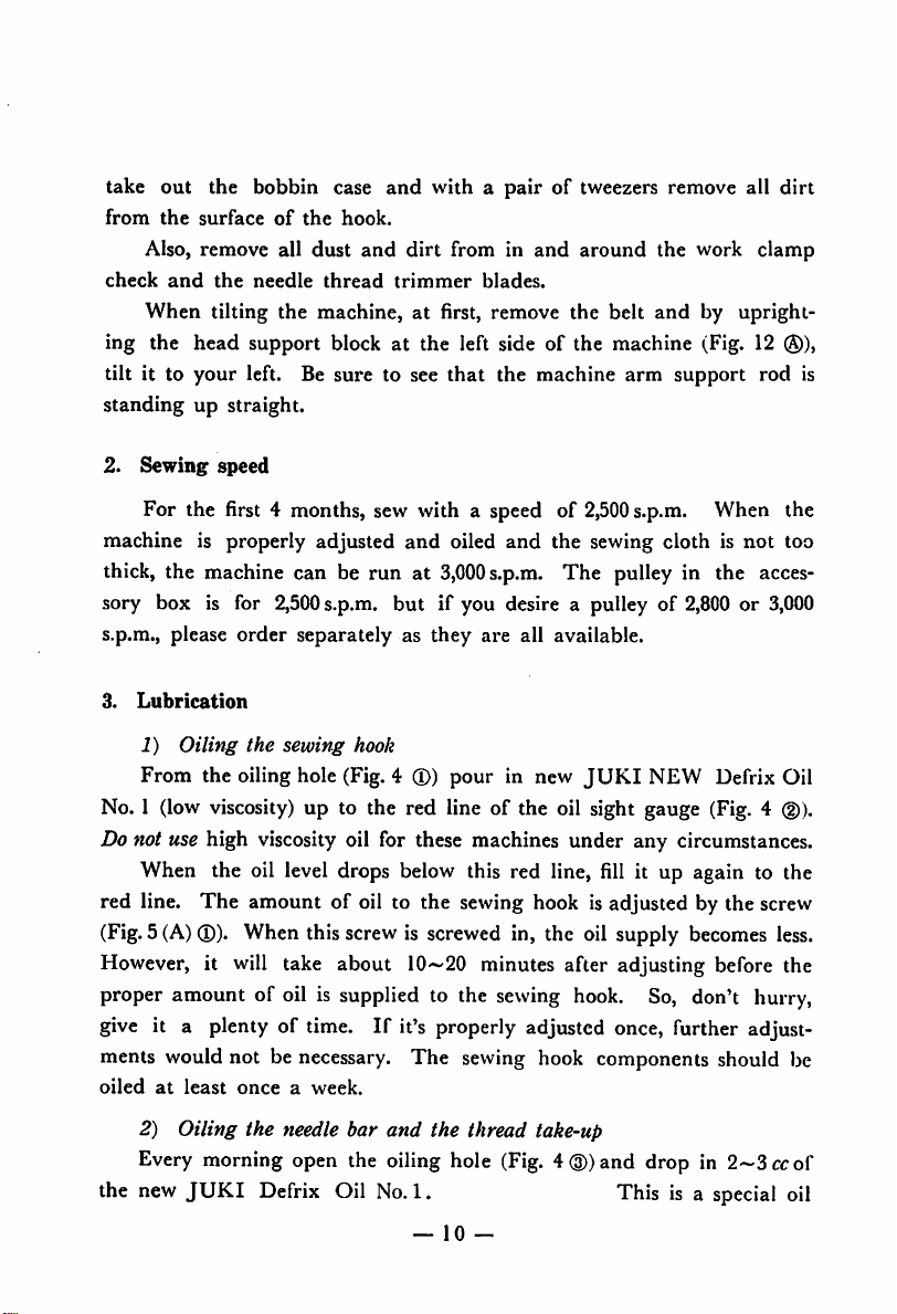
MODEL
LBH-761-762
763
HIGH
STRAIGHT
industrial
SPEED,
BUTTON
sewing
Instruction
SI*
-v;
HOLING
machines
Book
•
TOKYO
-
JUKI
INDUSTRIAL
CO.,lTD
Page 2
CONTENTS
I.
GENERAL
1.
Main
DESCRIPTION
OF
THE
MACHINES
specifications 1
2. Stitching types 2
II.
INSTALLATION
FOR
RUNNING
OF
THE
MACHINE
AND
PREPARATION
1. Installing the motor and the idler pulley 3
2. Installing the machine
3.
Rotating
4.
Installing
5.
How
to put on &
III.
HOW
TO
1.
Cleaning the
OPERATE
direction of pulley 6
the
chain
machine
remove
THE
arm
and
the
endless
MACHINE
bed 5
belt 7
2. Sewing speed 10
3.
Lubrication
4. Oiling the worm gears 13
5. Oiling the bevel gears 13
6.
Hand
oiling of other parts 14
7.
How
to insert
8.
Threading
9. Winding the bobbin
10.
Drawing
11.
Inserting
Running
12.
13.
Howtoprevent
14.
Slow speed running and how to stop the machine in
emergency
15.
How
to use the
the
needle
the machine 15
thread
out
the
the
the
thread
bobbin
machine
the
from the
case 18
cutting
bobbin
case 17
motionofknife 19
handle
Page
1
3
6
9
9
10
14
17
18
19
20
IV.
ADJUSTING
THE
VARIOUS
1.
The
bobbin
2.
The
needle thread tension 23
thread
tension 22
PARTS
22
Page 3
3. Adjusting the take-up spring 25
4. Timing of the needle and the hook 26
5. Adjusting the positions of seam and barring in relation to
the
button
hole
6. Adjusting the clamp carrying motion 29
7. Changing the number of stitches 30
8. Adjusting the
9. Adjusting the
10.
Adjusting the bobbin thread trimmer blade 35
11.
Adjusting the pressure of the work clamp check 36
12.
Adjusting the installing angle of the button hole length
regulating shaft bell crank 36
13.
Adjusting the device to prevent the knife from cutting when
the
needle
14.
How to change the number of stitches at barred ends 38
15.
Adjustment of the tension releasing movement 38
16.
Adjusting the cutting timing of the knife 42
17.
Adjusting the amount of the presser bar lift 42
18.
Adjusting the stop-motion components 44
19.
Adjusting the belt tension 45
20.
Adjusting the bobbin winder 45
thread
positions
needle
breaks
of the
knife
thread trimmer blades 32
27
32
37
V.
MALFUNCTIONS
1. Defective stitching conditions
2.
3. Reasons for malfunctions other
VI.
MAINTENANCE
VII.
THE
adjustment of
Malfunctions
measures
and
corrective
DIMENSION
AND
thread
other
measures
OF
GRAPH
CORRECTIVE
and
MEASURES
reasons due to mal
tensions 46
than
THE
tension:
MACHINE
OF
reasons
than
THE
and
corrective
stitching conditions
INSTALLING
TABLE
46
48
49
51
52
Page 4
I.
GENERAL
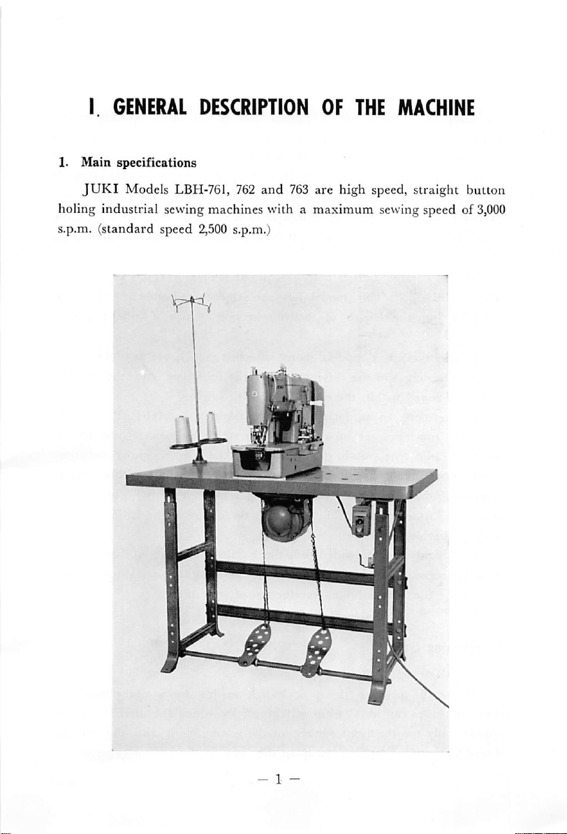
1.
Main
speciHcations
DESCRIPTION
OF
THE
MACHINE
JUKI
holing industrial sewing machines with a maximum sewing speed of
s.p.m. (standard speed
Models LBH-761, 762
2,500
s.p.m.)
and
763 are high speed, straight button
3,000
Page 5
LBH-761
garments
2.5-4
mm (3/32"-5/32") while the length of the button hole (width of
knife)is6.5
of up to
Model
LBH-762.
is designed to button hole men's shirts,
and all
mm-19
1"isrequired
other
garments
and the
mm (l/4"-3/4"). When,
for
This
gowns,
model's
pajamasorladies'
barred
ends
width
however,
widthis2.5-5
blouses,
of the
barred
button holelength
suits,
use
mm
under
ends
JUKI
(3/32"-
3/16") [one side is 1.2-2.5 mm (l/16"-3/32")] and the length of the button
hole
is 6
mm—25.4
When a large button hole is required such as
Model
LBH-762
1 >/4".
can be changed within the range of
for these machines, at an extra cost, by which by
LBH-763.
but the length of the button hole (width of
Besides
The
Furthermore, an automatic attachment known as AO-1 is available
the above models, many sub-class models are available.
feeding
mm
(1/4"
—1").
This
model
has
the
same
and the driving are of gear
54—340
sweaters
barred
endsasthe
knife)
feed
type and the stitches
stitches.
just
stepping lightly
etc. use the
Model
is 1/4"—
on the treadle type switch, the work clamp check comes down automa
tically and the sewing can be started and as soon as the sewing is
completed, the
automatic
slightly altering the table.
work
attachment
clamp check automatically
can
be installed, on order, to the
goes
up. This special
LBH
table by
It is highly recommended that the high speed feature ot these models
be advantageously utilized together with the automatic attachment AO-1
to increase the button holing production of your plant.
is
2.
Stitching
1)
types
Namesofstitching
types
As in the case of zigzag lockstitch sewing by a zigzag machine,
these machines can do
appears only on the front surface of the sewing cloth
thread appears in a zigzag form on the back of the sewing garment.
"whip
stitching"
— 2 —
by which the needle
and
the bobbin
thread
Page 6
Another
which
passes
the
bobbin
of
men's
2) Typesofstitching
Purl
With
these
stitchedtomake
ends can be purl stitched also.
"Whip
the
thread
II
typeofstitchingiscommonly
the
needle
straight
thread
through
tensionisstrengthened
the upper
threadisinterlocked,asin
shirts.
stitching"
machines,
is
eveninpurl
the
ends
appliedtogeneral
sturdier.
stitching"isgenerally
tension,
the
purl
stitching
INSTALLATIONOFTHE
called
"purl
and
the
center
However,ifyousodesire,
used
part of the
the
caseofbutton
stitching,
for
knit
fabric
the
goods
stitch
except
barred
but
canbeconvertedtowhip
MACHINE
stitching"
needle
hole
ends
by
thread
and to this
stitching
knit
goods.
are
the
barred
changing
stitching.
AND
by
whip
PREPARATION
1. Installing the motor and the idler pulley
As
shown
motor components ®. The head of the installing base bolt(Dshould come
out on the top surface of the table through the hole in the table.
Insertamotor
Install
the
motor
Appropriate
in
Fig.1,turn the table up side down and connect all
cushion(Dbetween
the
motorbyloosening
installing
bolt
power
(§)
for
from
this
FOR
the
the
motor
the
side
of the
machineisa
- 3 -
RUNNING
installing
adjusting
base
motor
300W,3-phase
and the
nut
base
(g)
and
(lower)
table.
pass
(5).
electric
Page 7
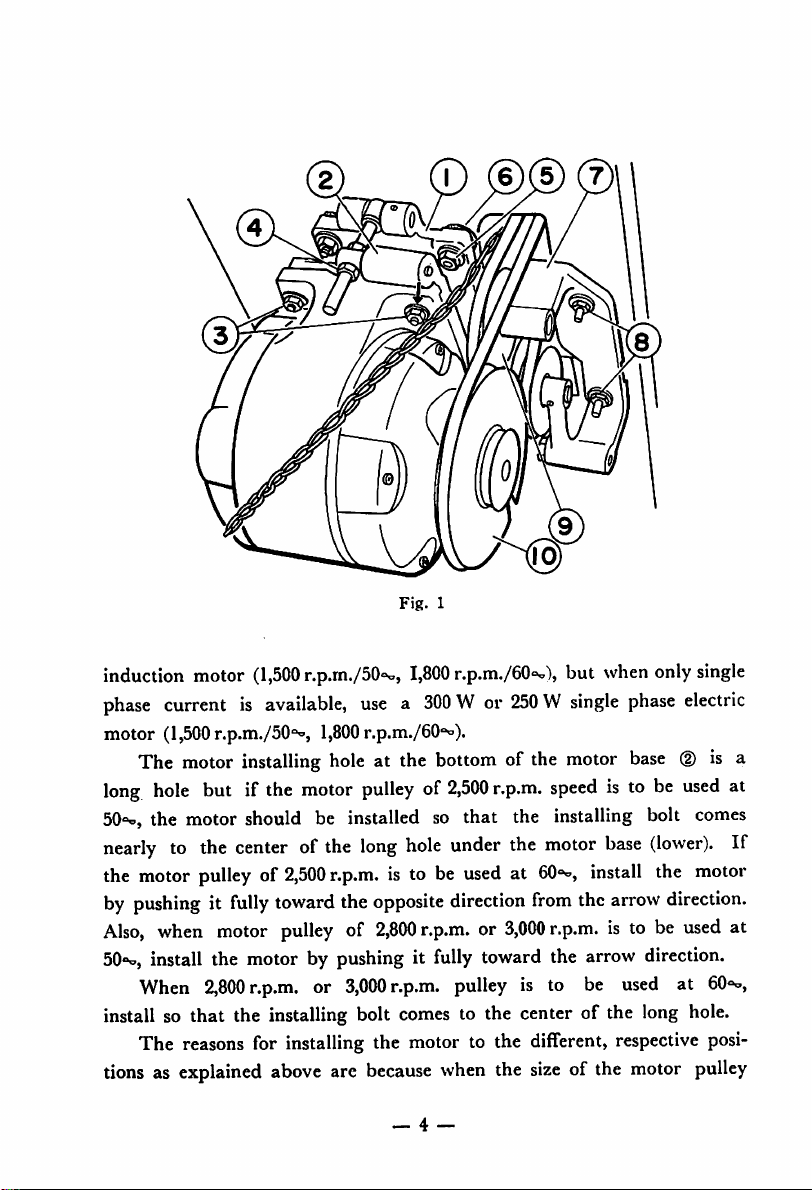
Fig.
1
induction motor
phase
currentisavailable,
motor
(1,500
The
motor
long
hole
50"^,
the motor should be installed so that the installing bolt
nearly
the motor
by
Also,
50°o,
install so that the installing bolt
to the
pushingitfully
when
install the
When
The
reasons
tionsasexplained
(1,500
r.p.m./50oo,
r.p.m./50'^,
installing
but if the
1,800
hole
motor
centerofthe
pulleyof2,500
motor
motorbypushingitfully
2,800
r.p.m.
for installing the motor to the different,
toward
pulley
or
above
r.p.m.
the
of
3,000
are
1,800
r.p.m./60°o),
usea300
r.p.m./OO*^).
at the
W or
bottom
pulleyof2,500
long
hole
under
is to be
opposite
2,800
r.p.m.
comes
because
_ 4 —
usedat60°°,
direction
r.p.m.or3,000
pulley
to the center of the long
when
250Wsingle
of the
r.p.m.
the
from
toward
is to be
the
size
but
motor
speed
motor
r.p.m.isto be
the
of the
when
is to be
base
install
the
arrow
only
phase
base
(lower).
the motor
arrow
direction.
direction.
used
respective
motor
single
electric
(D
is a
used
comes
used
at
GO'H',
hole.
posi
pulley
at
If
at
Page 8
is
changed,
motion
standard
accordingly.
Please note also
3-phase or single phase motor, use a motor base
when a steel frame motor is to be used, use a motor base
When a National Brand
used, the motor installing position is different, so be careful.
The idler pulley components @ should be installed to the bottom
surface
installing
baseofthe
motor
each
other.
2.
Installing
ihe
bell
device.
in
For this
installing
of the table by
hole
is rather
head
part and the
pulley
@
the
should
machine
should
not
contact
reason,
the
motor
that
when cast frame
single
hexagonal
large,besure
positionsofthe
be so adjusted that
arm
and
either
the
head
partorthe
follow
and
phase electric motor of
bolts
the
foregone
adjust
the
motor
B-7101-761-AAO
(§)of15/64",
method
respective
is used with
B-7101-761-BAG.
250
W is to be
Fig.
1.
that the belt is not contacting the
idler
bed
they
pulley
will
® and the
not be
stop-
as the
positions
either
and
As
the
touching
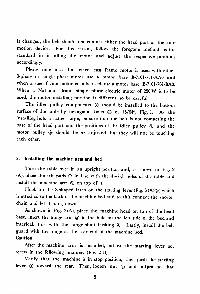
Turn the table
(A),
place the felt pads ® in line with the
install the
machine
Hook up the
is
attached
chain and let it hang down.
As
base, insert the hinge arm
interlock
guard
Caution
After
screw in the following manner: (Fig. 2 B)
Verify
lever
to the back of the machine bed
showninFig.2(A),
this
with the hinge at the rear
the
that the
(J)
toward
over
in an upright
arm ® on top of it.
S-shaped
with
the
hinge
machine
arm is installed, adjust the starting
machineisin
the
rear.
position
latch on the starting lever
place
the
machine
(3)
to the hole on the left side of the bed and
shaft
bushing
endofthe machine bed.
stop
Then,
loosen
- 5 -
and, as
4~70
showninFig.
holes
of the table and
(Fig.5(A)(D)
and
to this connect the shorter
head on top of the head
®.
position,
nut ® and
Lastly,
then
install
push
adjust
which
the belt
lever
set
the starting
so
that
2
Page 9
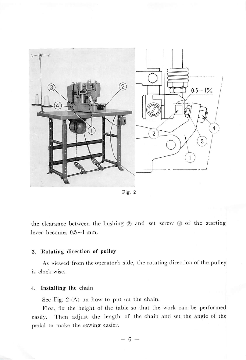
the clearance between the bushing
lever
3.
becomes
Rotating
0.5~lmm.
direction
of
pulley
(2)
and set screw(Dof the starling
As viewed from the operator's side, the rotating direction of the pulley
is
clock-wise.
4.
Installing
the
chain
See Fig. 2 (A) on how to put on the chain.
First, fix the height of the table so that the
easily.
Then adjust the length of the chain and set the angle of the
vvork
can be performed
pedal to make the sewing easier.
- 6 -
Page 10
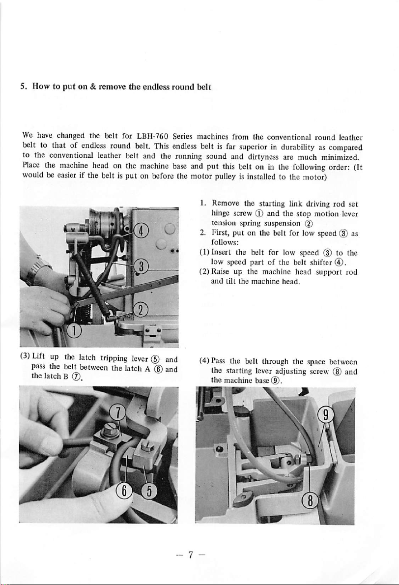
5. How to
We have changed the belt for LBH-760 Series machines from the conventional round leather
belt
to the conventional leather belt and the running sound and dirtyness are much
Place
wouldbeeasier
(3)
Liftupthe
pass
the latch B (J).
put
to that of
the
machine
the
belt
on & remove the endless
endless
round
belt.
This
head
on the
machine
if the belt is put on
latch
tripping
between
the
before
lever
(5)
latchA(D
round
endless
base
the motor
and
and
belt
belt is
far
superiorindurabilityascompared
minimized.
and
put
this
belt
on in the
pulleyisinstalled
1.
Remove
hinge screw ® and the stop motion lever
tension spring suspension (D
2. First,
follows:
(1) Insert the belt for low speed (3) to the
low speed part of the belt shifter
(2) Raise up the machine
and
(4) Pass the belt through the space between
the starting lever adjusting screw (8) and
the
the starting link
put
on the belt for low speed (3) as
tilt
the
machine
machine
base
(9).
following
to the
head.
motor)
head
driving
support
order:
rod set
®.
rod
(It
i
Page 11
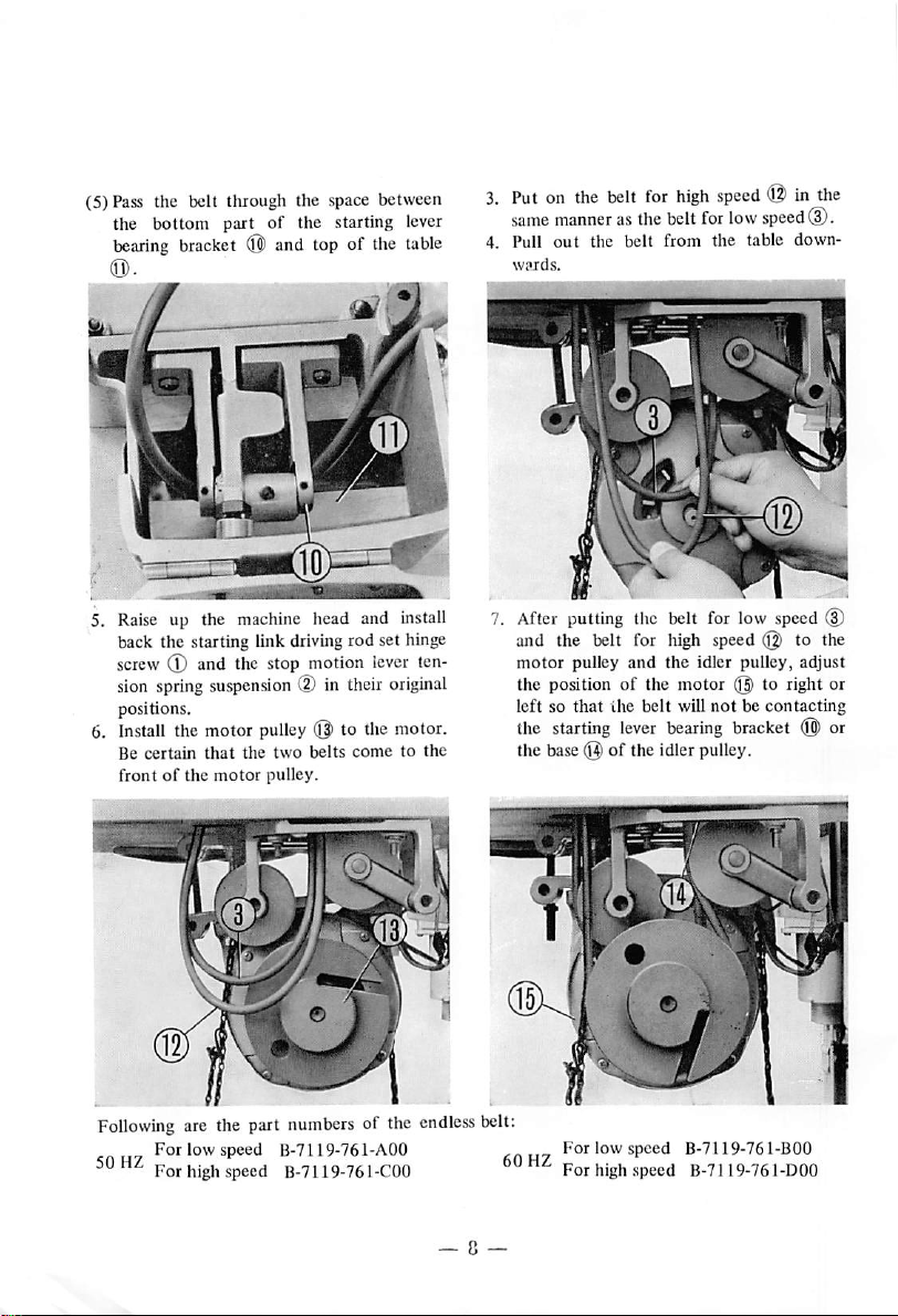
(5) Pass the belt through the space between
the
bottom
bearing
part of the starting lever
bracket
(0 and top of the
table
3.
Put
same
4. Pull
on the
manner
out
belt
for
high
speed
asthe beltfor lowspeed®.
the
belt
from
the table down-
© in
the
K
5. Raise up the machine head and install
back the starting link driving rod set hinge
screw ® and the stop motion lever ten
sion
spring
positions.
6.
Install
Be
frontofthe
the motor
certain
suspension
that
motor
the
(D in their
pulley
two
pulley.
m
(I|)
to the motor.
belts
cometothe
original
After putting the belt for low speed @
and the belt for high speed @ to the
motor
pulley and the idler pulley, adjust
the position of the motor @ to right or
leftsothat
the starting lever
the base
the
belt
will
bearing
(Q'
of Ihe idler pulley.
notbecontacting
bracket ® or
Following
For
For
are the part
low speed
high
speed
numbers
B-7119-761-A00
B-7U9-761-C00
of the
endless
belt:
For
For
low
high
speed
speed
B-7119-761-BOO
B-7119-761-DOO
Page 12
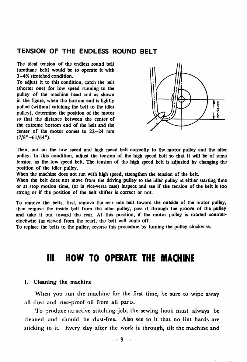
TENSION
The
ideal
(urethane belt)
3-4%
stretched
To
adjust
OF
THE
tensionofthe
would
condition.
it to
this
condition,
ENDLESS
endless
be to
operateitwith
catch
round
the
ROUND
belt
belt
BELT
(shorter one) for low speed running to the
pulleyofthe
in the figure, when the
(without
pulled
pulley), determine the position
so
that
the
extreme
center
(7/8"-61/64").
Then,
put
pulley. In this condition, adjust the tension
machine
head
bottom
andasshown
end
catching the belt to the idler
of
the
distance
bottom
of
the
motor
between
endofthe
comesto22-24
the
the
center
belt
on the low speed and high speed
is lightly
motor
and
the
mm
of
belt
of
correctly to the
the high speed
motor
beltsothat
pulley
and
the idler
it will beofsame
tension as the low speed belt. The tensionofthe high speed belt is adjusted by changing the
positionofthe idler pulley.
When the machine does not run with high speed, strengthen the tension of the belt.
When the belt does
or at
stop
strong or if
motion
not
time,
the
positionofthe
move from the driving pulley to the idler pulley at either starting time
(or
in vice>versa case)
belt shifter is
inspect
conectornot.
and
seeifthe
tensionofthe
beltistoo
To remove the belts, first, remove the rear side
belt
toward
the
outsideofthe
motor
pulley,
then remove the inside belt from the idler pulley, pass it through the grooveofthe pulley
out
and take it
clockwise (as viewed
toward the rear. At this position, if the
from
tlie rear), the
belt
will
come
off.
motor
pulley is rotated
counter
To replace the belts to the pulley, reverse this procedure by turning the pulley clockwise.
1.
Ill HOW TO
Cleaninj;
the
machine
OPERATE
THE
MACHINE
When you run the machine for the first lime, be sure to wipe away
all dust
and
rust-proof oil from all parts.
To produce alractive stitching job, the sewing hook must always be
cleaned
sticking to it. Iwery day after the work is through, tilt the machine
and
should
be
dust-free.
Also
— 9 -
seetoit
that
no
lint
hards
are
and
Page 13
take
out
the bobbin case
from
the
surface
Also, remove all dust
check
and
the
needle
of
the
hook.
thread
and
and
dirt
trimmer
with a
from in
pairoftweezers remove all
and
blades.
When tilting the machine, at first, remove the belt
head
ing the
tilt it to your left. Be sure to see
support block at the left side of the machine (Fig. 12 ®),
that
the machine
standing up straight.
2.
Sewing
speed
around
arm
dirt
the work clamp
and
by upright-
support rod is
For the first 4 months, sew with a speed of
2,500
s.p.m. When the
machine is properly adjusted and oiled and the sewing cloth is not too
thick, the machine can be run at
sory box is for
2,500
s.p.m.
3,000
s.p.m. The pulley in the acces
butifyou desire a pulley of
2,800or3,000
s.p.m., please order separately as they are all available.
3.
Lubrication
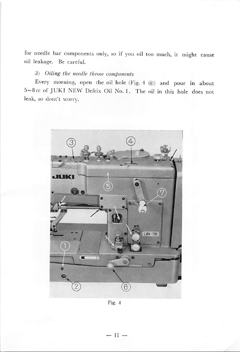
J)
Oiling
From the oiling hole (Fig. 4 ®) pour in new
No. 1 (low viscosity) up to the red line of the oil sight gauge (Fig. 4
the
sewing
hook
JUKI
NEW Defrix Oil
(D).
Do not use high viscosity oil for these machines under any circumstances.
When the oil level drops below this red line, fill it up again to the
red line. The amount of oil to the sewing hook is adjusted by the screw
(Fig.5 (A)
However, it will take about
proper amount of oil is supplied to the
(D).
When this screw is screwed in, the oil supply becomes less.
10-^20
minutes after adjusting before the
sewing
hook.
So, don't hurry,
give it a plenty of time. If it's properly adjusted once, further adjust
ments would not be necessary. The sewing hook components should be
oiled
at
least
onceaweek.
2) Oiling the needle bar
Every morning open the oiling hole (Fig.
the new
JUKI
Defrix
Oil
and
the thread take-up
4®)
and drop in
No.
1. This is a
2~3ccof
special
oil
—
10
—
Page 14
for
needle
oil leakage. Be careful.
3) Oiling the needle throw components
Every
5~8ccolJUKI
leak, so donl'l worry.
bar
components
morning,
NEW Defrix Oil No. I, The oil in this hole does not
open
only,soif
the
oil
you
hole
oil
too
(Fig.4@)
much,itmight
and
pour in
%/
cause
about
Page 15
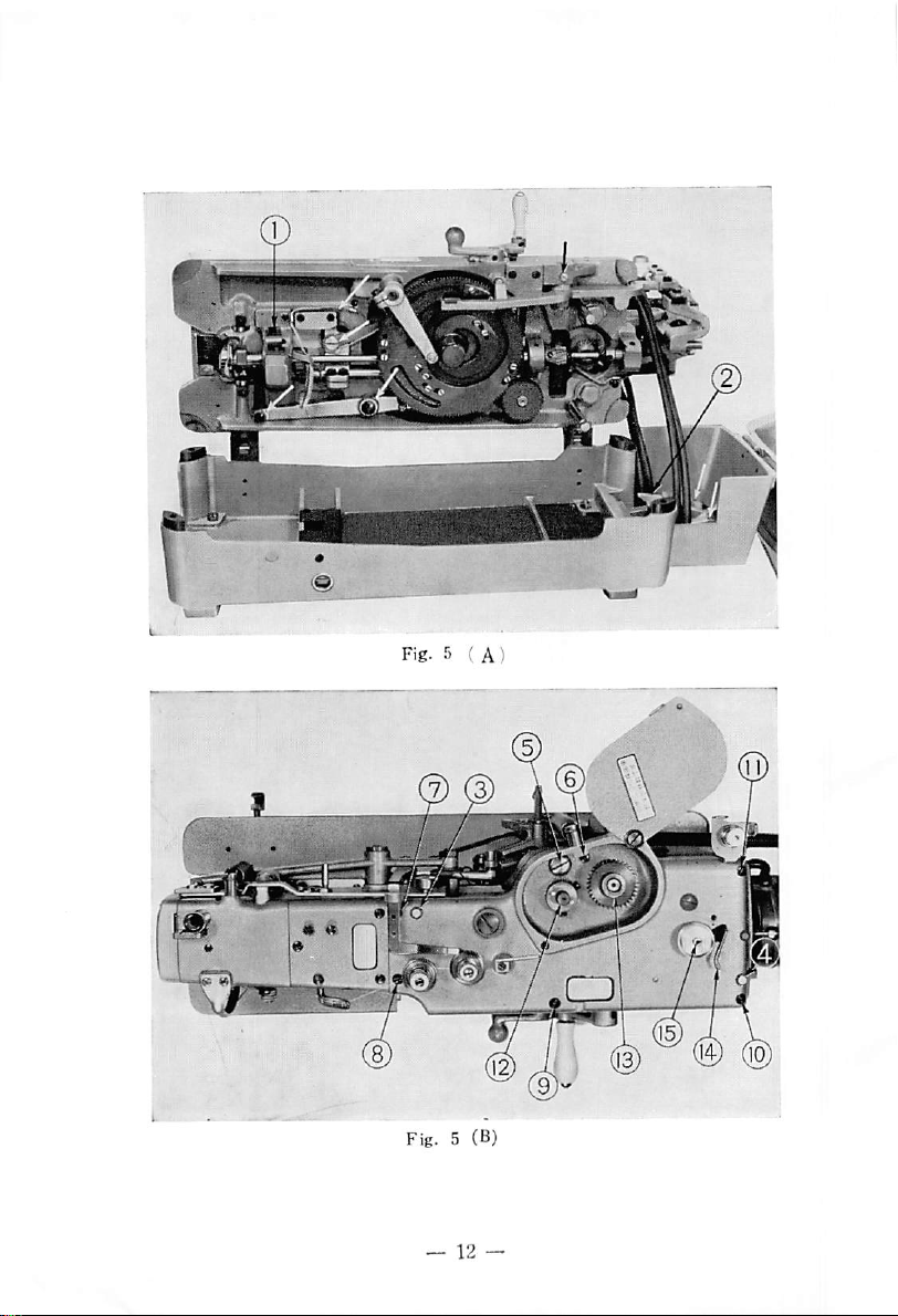
Fig. 5 (B)
) ®
(HJ
(10
Page 16
4.
Oiling
the
worm
gears
The
worm gear components are lubricated by an oil reservoir, so
just change the oil once a year. To change the oil, remove screw (Fig.
5 (B)
(§))•
and
if
the
machine
is
tilted,
the
oil will flow
out
from
this
hole. After the spent oil is completely drained out, pour in about 70cc
of
New Defrix Oil No. 3 oil
5.
Oiling
the
bevel
If
the top cover (Fig. 4
gears
and
retightcn
(D)
is removed, the bevel gear case (Fig. 6
this screw
(§).
®) will appear. Remove the oil plug screw (Fig. 6 d)) and pour in
The
grease into this hole.
onceayear.
To
remove the cover, first, remove the tension release lever hinge
screw (Fig. 12
(T))
and
the operator. Then, remove the top cover set screws (Fig. 5
also remove the spur gear bushings (one at Fig.5 (B)@
greasing of this hole should be done at least
tilt the tension release lever (Fig. 12
and
one at @ below
(§))
towards
and
the spur gear). Finally, insert a screw driver to the slit of Fig. 12
and @ of the top cover and if it's lifted up evenly, the cover will
come
off.
When installing the top cover, push back the bobbin winder trip
latch (Fig. 5
(g>)
to the rear then by taking out the oil wick which is
dangling at the bottom surface of the top cover (the wick which is oiling
the shaft bushing of the bobbin winder pulley, Fig. 5 (B)@) from the bot
tom sideofthe oil hole (Fig. 4
leveling the top cover, plug it into the worm wheel shaft (Fig. 6 d))
the
cam
driving shaft (Fig. 6
arm.
Then,
after pegging in
retighten the top cover set screws
of
the
2 set screwsofthe
the
level surfaceofthe
between
the
rear
shaft
oil reservoir felt (Fig. 6 (D).
(D)
spur
and
<D)tothe
and
the
and
gear
top surfaceofthe
put
it on the top of the machine
cover position
install the
bushing
spur
should
tightened. Finally, insert
cover
and
and
pin
(Fig. 5 (B) d) ®)»
gear bushing. Each
be
matched
the
with
oil wick
by
(§)
—
13
—
Page 17
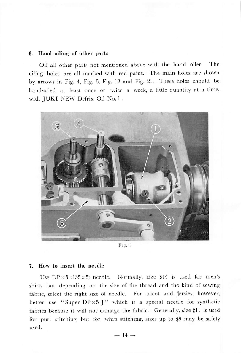
6.
Hand
oilingofother
parts
Oil all other parts not mentioned above with the hand
oiler.
The
oiling holes are all marked with red paint. The main holes are shown
by arrows in Fig. 4, Fig. 5, Fig.12and Fig.
hand-oiled at least once or twice a week, a little
with
JUKI
NEW
Defrix Oil No. 1.
21.
These holes should be
quantity
N
at a time,
7.
How
to
insert
the
needle
Use
DPx5
(135x5) needle. Normally, size #14 is used lor men's
shins but depending on the size of the thread and the kind of sewing
fabric, select the right size of needle. For tricot
better use
"Super
DPx5
J"
which is a special needle for synthetic
fabrics because it will not damage the fabric. Generally, size
for purl stitching but for whip stitching,
used.
—14—
sizes
and
jersies, however,
#11
is used
up to#9may be safely
Page 18
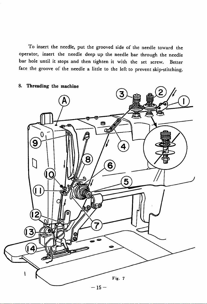
To insert the needle, put the grooved side of the needle toward the
operator, insert the
bar hole until it stops and then tighten it with the set
face
the
grooveofthe
8.
Threading
the
needle
deep up the
needlealittletothe
machine
needle
bar through the
lefttoprevent
screw.
skip-stitching.
needle
Better
-15
Page 19

For button holing, use best grade cotton thread of even size and
even
left
twist
for
the
needle
and
the
strands
from
3~6
nylon or super polyester threads can be used as
nylon
synthetic fiber
threadisto be
thread.
thread.
fiber twists.
used,
be sure to
The
sizes
For
useaspecial
the
should
needle
well.
be
from
thread,
However,
sewing
#40~60
polyester,
when
hook
for
Right twist or inferior grade thread will, not only mar the beauty
of stitched job, but will invite thread breakage, thus lowering the
effici
ency of the button holing operation. Nothing is gained by inferior grade
thread, so be sure to select the best grade of thread for this operation.
Refer to Fig. 7 for the
orderofneedle threading.
The needle thread, which came out of the thread spool, should be
passed in the following
The thread guide pin ©^tension disc No. 1
(D^three-hole thread eyelet • tension disc No. 3 »take-up spring
order:
(§)—•tension
disc No. 2
(D
tension thread guide @ • take up thread guide A ® • thread take up
® • take up thread guide B ® • thread check wire ®
thread guide ©
•needle
thread guide ®
•needle
eye
®.
•needle
bar
In passing the thread through the needle eye, be sure to pass it from
the opposite side of the operator.
Please note also that, as shown in Fig. 7, the tension disc No. 1
(D
has a hole with a slit, so pass the thread through the center hole of
this slit by lifting the upper tension disc.
--
lb
Page 20

m
m
.f_r<
9.
Winding
The
caseofneedle thread, synthetic threads can also be used.
The bobbin thread should be passed in the order as shown in Fig.
9. First, insert the bobbin into the pulley shaft ® and pass the thread
which came out of the shaft in the order of thread guide eyelet
bobbin winder tension disc
the
bobbin
the
bobbin winder trip latch d) is pressed against the bobbin, the
thread
fixed
amount
cannot
the
bobbin
optimal
sizes
in
the
will be wound
thread
of
the
d)—»
counter-clockwise
during
the
bobbin
thread
are
150—100
thread guide eyelet @ and wind it to
direction
as
viewed
runningofthe machine
is wound, the winding will stop automatically.
be wound when the machine is not running.
from
and
and
as in
above.
bobbin
when the
The
bobbin
the
(g)—»
If
10.
Drawing
out
the
thread
from
Fig.
—
(B)
the
17
10
—
bobbin
case
Page 21

The
order of
drawing
out
the
thread
from the bobbin case is shown
in Fig. 10 (a) (b) (c).
Hold the bobbin inside the bobbin case so you can see clearly from
the
front
and
when
the
threadisdrawn
out
from
the
bobbin
case, see
to it that the bobbin turns in the counter-clockwise direction. (Fig. 10c)
11.
Inserting
the
bobbin
case
Fig.
11
See Fig.11for inserting the
the
bobbin
sound
might
inserted
12.
Running
Step
insert
work
clamp
the
right pedal is stepped on fully. After the
case is correctly inserted to its position in the hook, a click
can
be
jump
out
in.
on
the
the
sewing cloth.
the
heard.
when
machine
left
If
the
pedal
check is lowered,
the
machine
and
the
When
the
bobbin
bobbin
the
machine
—
case
into
the sewing hook.
case is
not
properly
starts. So, be sure
work
clamp
check will go up.
left lifter pedal is raised
will
starttorun
button
18
—
holing is through
that
just
When
inserted,
it's snugly
Now
and
the
as soon as
and
it
Page 22

the
knife
has
cutaholeinthe
Then,
raise
up the
This
machineisequipped
machine
work
starting
way, the starting pedal will not start.
at a
running, it will
Caution
from
clamp
pedalissteppedonwhile
When
slow
the starting
speed
If the starting
stopping
speed
13. How to prevent the cutting motion of knife
gone,
produce better sewn garment. This machine is so constructed
the
cutting.
thread is all
wrong with the
of the knife stop lever (Fig. 12
until the machine stops. This will prevent the machine from cutting.
time,
or the
When the needle thread is broken or when the bobbin thread is all
needle
When
stop-motion
it is better to
thread is
However,
gone,
the
work
starting
checktogo
pedalissteppedonlightly,
but if
run
faster.
pedal
the
knife
resew
broken,
when
the
knife
bobbin
thread is all gone or
sewing
cloth,
the
machine
clamp
while
is left in the
might
device
check
and
pull
withasafety
the
work
clamp
up
before
the
pedalissteppedonfully
cut at
without the
the
the
stepped-in
high
may not
machine
lifter
speed
function
motion
clutch
pedalisstepped
it automatically
the
needle
will
condition, push down the
(D)
thread
cut at the
with your
is
finish
when
hand
will
stop
automatically.
out the
sewn
which
prevents
checkisraised
stops
and
evenifthe
the
machine
during
condition
without
properly.
of the cutting
prevents
intact
of the
you detect
at the
shiftingtolow
the
but
sewing
finger
(Fig.
and
hold it there
Be
knife
the
cloth.
or the
down
half
will
run
this
slow
machine
careful.
knife
that
when
from
bobbin
cycle.
something
12
the
to
®)
14. Slow speed
1) Low speed
When the machine is to be adjusted or when the stitching condition
running
running
and
how to stop
—19—
the
machine in emergency
Page 23

is
extremely
bad,itcanberun
(D)islowered
even
though
and
the
kept
starting
at a
low
speed.Ifthe
there,
the
machine
pedalissteppedonfully.
will
run
at a
handle
slow
(Fig.
speed
4
2) Stopping the machine in
If the
needle
the
sewingiscontinuedinthis
ped.
In
suchacase,
this,
turn
the
stop
bolt.
clamp
to
or starting the
15.
also
checktothe
the
original
How
to
This
handleisused
when
breakage.Ifthis
work
clamp
the same manner as in normal
if
this
handleisreversed,soif
move
carrier
the handle
will
should
hand
stop
The
machine
original
position
machine,
use
the
handle
it is
desiredtoresew
handleisrotated
carrier
move.
(Fig.12@)
forward
break
the
machine
crank
will
sewing
and
complete
for
emergent
emergency
during
by
sewing.
you
and backward, a little at a time, and the
the
running
condition,
the
sewing
canbestopped
180°
counter-clockwise
stop
instantly.
position,
either
the
stoppingasmentioned
from
and
the
want
return
turning
sewing
in
cycle.
the point just
the
clock-wise
work
clamp
The carrier will not move even
to
move
of the
cloth
machine
mayberip
emergently.Todo
untilithits
To
the
return
the
handle
before
check
the
hand
the
stop
(Fig.4(2))
above
the thread
direction,
will
carrieralittle,
work
crank
move
and
the
and
the
in
Caution
1)
During
(Fig.12(§))ispulled
12
(D)
is rotated and if the machine is started by turning the handle
before
with the stop link
the
the
machine
the
groove
starts.
maintenanceofthis
to the rear by hand and the
of the stop cam
(Fig.12©), the
—
knife
20
machine,
(Fig.
12
often cuts at the instant when
ifthe
stop-motion
driving
@)istightly
lever
pulley
(Fig.
interlocked
Page 24

Fig.
12
This action results only when, as shown in Fig.
of the knife bar driving lever bell crank (i) is not
(B)
(D,
ratchet pawl
(D
and
ratchet pawl (A) ®
In such a case, pull the finger
crank
(T)
towards you.
part @ will be released and the pawl
of the claw part
thus creating a space between the ratchet pawl
and
the claw part(Dis trapped between them.
(J)
of the knife
The
interlocking of the pawl
(g)
will return to the under side
(?)
and the above trouble will not occur again.
13,
the ratchet pawl
"riding"
bar
driving lever bell
(3)
and the claw
When the machine stops correctly and the stop motion cam and
the interlocking link are interlocked each other, the claw part
w-ill
starting lever
(D
screw
bell
and is pushing up the(Dpart of the knife bar driving lever
crank.
So
contact the knife bar driving lever bell crank hinge
the
above
mentioned
trouble
will
not
occur.
2) Use the handle only when the needle is not piercing the cloth.
It
will be safe if the
at
the
correct
handleisrotated
angle.
when
the
driving
—
21
—
pulley is
atop the
(5)
of the
stopping
(B)
Page 25

Fig.
13
iV.
ADJUSTING
1.
The
bobbin
thread
tension
THE
VARIOUS
PARTS
The optimal bobbin thread tension is for the bobbin case to gradually
slide downwards when the tip of the thread is held by your hand and
lightly shaken up
If
the bobbin thread tension is too strong, wobbling stitching will
result
and
and
down. (Fig.
further, it will invite
14)
thread
breakage of the needle
thread
due to the strong needle thread tension caused by the strong tension of
the
ing
bobbin
job.
thread, a detrimental factor to produce an attractive stitch
—22—
Page 26

FiM. M
On
the
other
hand,
bobbin thread will not stay taut
cloth, making it impossible to do finish sewing -of the
cycle, causing slipping
2.
The
needle
1)
The
mannertoproduce
When
ing"
up.
On
all
three
No. 2 floats up
thread
needle
the
machineisat
the
start
and
tension discs
and
thread
beantijul
if
the
bobbin
and
will
thread
''float"
tensionistoo
weak,
on top of the sewing
starting
outofthe needle thread.
tension
tensionofthis
whip
rest, all
return
are
sewing
working. At all
stitchingofbarred
machine changes in
the
thread
around
tension
the
edgeofthe
barred
ends.
ends,
the
discs
button
the
tension disc
following
are
forms a whip stitching. Also when the machine is
running at a low speed, the tension disc No. 3, too, is floating up.
At the
a low speed, so
will
No. 1
second
barred
at
have
been
working
and
No. 3 will be working.
the
end,
second
and
the
speedofthe
barred
at
the
end,
first
machineisswitched
only
the
tension disc No. 1
barred
end, the tension discs
Accordingly, the three tension discs will adjust the following:
0
Thread
second
tension disc No. 1
barred
end.
adjusts
the
needle
thread
tension,
the
sewing
"float
hole,
at
the
to
—
23
—
Page 27

(D
the
(3)
first
Thread
needle
Thread
barred
tension disc No. 2 adjusts the seaming thread tension of
throwing.
tension disc No. 3 adjusts
end.
the
needle
thread
tensionofthe
2) To produce good stitching tension
Once
the
thread
tension is
for
properly
purl
stitching
adjusted, it is
not
necessary to
adjust the tension of tension discs No. 1 and 3. Just adjust the tension
disc No. 2 only.
To produce optimal stitching condition, do as
(D
Adjust the bobbin thread tension according to Par. 1, above.
(D
Adjust the tension disc No. 1 so that a beautiful whip stitching is
follows:
produced at the second barred end.
If
the
tension disc No. 1 is
tighter
(3)
end
and
the bobbin
thread
Adjust the strength of the tension disc No. 3 so that the first barred
forms a
beautiful
whip
stitching.
strengthened,
is pulled
out
more.
the
needle
thread
gets
Finally, adjust the strength of the tension disc No. 2 so that the
mounts
erect.
of
the
starting
If
the
tension disc No. 2 is strengthened, the wobblingofstitches
apd
returningofthe needle
throwing
stand
up
will be prevented. However, if it's strengthened too much, the needle
thread
CAUTION
needle thread tension is too weak at the whip stitching places, a so-called
" double locking" (hooking up of the stitch by the hook point of the
second
the sewing surface) will result
tensionofthe needle
the
might
break. Be careful.
The
first and the second barred ends are whip stitching
stitching
bobbin
thread
thread
before
thread
the
first
stitching
and
may
should be so
cut
the needle thread.
adjusted
will not come up on the surfaceofthe cloth.
but
threadispulled
to the
extent
if the
up to
The
that
3) To
produce
good
stitching
tension
for
whip
stitching
Loosen the tension disc No. 2 fully for whip stitching. Also adjust
the
bobbin
thread
tension
justsostrong
—
24
—
as to allow
the
bobbin
case to
Page 28

droop down
bobbin case is held by the hand
nance
with
slowly
the
tensionofthe
when the bobbin thread which came out from the
and
waved strongly.
bobbin
thread,
adjust
Then,
the
second
in conso
barred
end tension by changing the tension of the tension disc No. 1 and adjust
the tension of the
by
the
tension disc No. 3.
starting
and
returning
as well as the first
barred
end
It is a common practice to use the same size of thread for the
needle
3.
and
Adjusting
The
tension
bobbin
Fig.
the
and
threads
take-up
15 (A)
the
for all
spring
moving
the beauty of stitches as well as
locking".
The
tensionofthe take-up spring at the
whip
stitching.
rangeofthe
thread
Fig.
15 (B)
take-up
spring
greatly
affect
breaking due to the " double
start
of sewing should be
25—30g when it is pulled along the circumference of the tension discs.
(Fig. 15 (A)).
and
loosening
post No. 3 assembly (Fig. 15
The
moving
-7/16").
Please note
must
be 2- times
stitch
machine.
This
can
be
the
screw ® Fig. 15 (B)
rangeofthe
that
the
tensionofthe
stronger
than
adjusted
(B)\
take-up
the
by loosening
after
spring
take-up
removing
should
take-up
springofa
the
screw (D Fig. 24
the
thread
be
9—11mm.
springofthis
conventional
tension
(3/8"
machine
lock
Page 29

4.
Timingofthe
i)
Height0/the
When the
needle
needle
needle
bar is
and
bar
lowered
the
hook
to the
lowest
point,
the
space
hciwcen
the needle plate surface and the bottom part of the needle bar should
be
10.3
mm (3/8").
the timing gauge in the accessory box (Fig.
screw
driver into the hole
tionofthe needle
12.6
bf
2)
Timing
The
best timing of the needle with the sewing hook is when the
Fig.
the
If
the height of the needle bar is not correct, use
16(1))
and by inserting a
(Fig.21(g))
bar
connection (Fig. 27
16
hook
adjust the correct installing
).(»—
Fig.
17
posi
l.Kntii)
needle stitches right in the center of the needle hole of the needle plate.
When the needle has begun to rise from its lowest point and the
point of the hook point is timed with the center of the needle, the space
between the upper
(1/16"). (Fig.
better.
For correct timing adjustment, use timing gauge of Fig.
the driving pulley in the
17).
part
of the needle eye and die hook point is 1.6~l.8 mm
For jer.sies
and
knit goods, 1.6mm (l/16"i space is
16.
regular
direction,
and
when the needle has
Rotate
begun to rise up from the lowest point, insert the 2 part of timing gauge
(Fig. 16) between the needle
needle
center
bar
contacting the gauge, time the point of the hook with the
of
the
needle.
The
bar
clearance
and
the needle plate and with the
between
the
needle
and
the
hook
point is about 0.05mm but when the needle is swung from right to
left, or vice-versa, be sure that they don't touch each other.
—26—
Page 30

I-ig. 18
To
To
i-emove
them
out.
(§)olthe
adjust the timing ol' tiie hook, loosen tlie set screw
the
hook
To
sewing
replace
sleeve
hook, loosen
the
sewing hook,
with
that
ofthe
the
set screws (Fig. 18 d))
time
the tipofthe oiling
hole
oi"
the
oil
reservoir
(l'"ig.18(T;k
and
take
tube
and
install
the hook back. In doing so, the bobbin case stop must also be
removed
positions
but
to replace it, be sure to adjust the right
of
the bobbin case stop so that the
thread
and
left installing
will easily pass
through the space of tlie corner between the bobbin case stop.
5.
Adjusting
button
1)
hole
The
Ihroivof/he
the
positions of seam
needle
and
barringinrelationtothe
Fig.
19
—27—
Straight
Page 31

For
the guide
of
A
needle
barred
position;
width.
2)
seaming or barring, this machine always keeps the left side as
and
throws
Fig. 19 is
Adjusting
Wi
the
the
called
is
Wi
called
and
needle to the
the
right
needle
the
seam
W2
right
position;
width
and
keeps on stitching.
B is
called
and
W2 is called
the
left
the
Please
adjusting
is
returned
when
the
this
screw
in mm
3)
When
to left
refer
to Fig. 20.
screw
adjusting
and
Adjusting
and
(T)
is screwed in
toward
the
screw
is
returned.
the
graduation
the
the screw
(2)ispushed
if it's lowered, it will move to
operator.
(2)
The
right-left
The
is screwed in
graduation
(D
needle
Fig.
20
seam
width
and
will get smaller
The
barred
indicates
positions
and
(D
the
W1 gets
width
will get
indicates
barred
bigger
when
W2 will
narrower
the
width
when
this screw
get
seam
also in
up, the needle position A will move
right.
—
28
—
When
the
adjusting
the
bigger
when
width
mm.
Page 32

screw
(§)
is screwed in, the needle position B
returned,
knife
so that the thread of the right side of the seam width will not be cut
by the knife. Finally, adjust the barred width.
CAUTION
® After all of the above adjustments are made, be sure that all the
locking nuts
(D
Due to a certain amount of rattling by the throw of the needle
it will move to
4)
Orderofadjustment
Adjust
the right
needle
from cutting into the
are
firmly tightened.
right.
position
seams.
and the
Next, adjust the left needle position
moves
seam
tc left and it it's
width to prevent the
and tighteningofthe cloth by the needle, there may be a slight tolerance
between the graduation figure and the actual button holing length. So,
make correct adjustments by actual sewing.
@ The needle is so constructed to throw more than the hole length of
the
work
clamp
widened to over 3.8mm (5/32")
the
driving
and return
check.
pulley
sewing,
So,
after
adjusting
and
moving the needle position,
with your hand and
the
needle
will not contact the work clamp
the
ascertain
barred
widthsothat it
that during both start
rotate
check.
After the driving pulley is rotated by hand, be sure to return the
pulley
camofthe
to the
stop.
angle
where
the
stop
linkisinterlocking
with
the
groove
is
6. Adjusting
Pull out the bed slide
and by
show same graduation as the width of the knife, tighten the nut.
sliding
the
work clamp
the regulating
carrying
(A)
Fig. 20 to your right, loosen nut(DFig.
hinge
motion
stud
(2)sothat the
scale
(3)
will
The graduation is set to the amount of carrier corresponding to the
width of the knife, but if desired, this carrying amount may be increased.
—
29
21
Page 33

7.
Changing
the
number
of
Fig.
stitches
21
<K
Page 34

By changing the spur gears, this machine can change the number
of
stitches in a
When
gear
(D
A, B, C
alphabets show the pairing
the
same
which is on
wide
rangeasshowninTable
the
numberofstitches
are
desired to be changed,
below.
change
the
Fig. 22. All the spur gears have alphabet marks such as
etc.
or
alphabet
the
numbers
gears.
rear
side,
such
number
The
figures
indicate
as 123, 152
etc.
branded
on
them.
of each gear, so be sure to interlock
branded
the
numberofstitches
on the
gear
required.
d) Fig. 22,
The
When installing the gear, insert the pin holes firmly into the 2 pins
of
the
spur
gear
bushing0,Fig. 22.
As the shaft
(3)
and
the shaft
(3)
(Fig. 22) rotate freely to opposite
directions, respectively, insert the gear into the shaft and after interlock
ing, rotate the gear by pressing it downwards and it will go in easily.
This machine is provided with the following 15 gear sets, as acces
sory parts, besides the sets in the machine, but if other gear sets are
desired besides these sets, please order them separately.
'FABLF
Set
A
B
C
D
!•:
F
G
H
The
Small
Teeth
No.
ones
21
23
24
25
26
27
28
29
gear
Stitch
No.
circled
Large
Teeth
No.
54
62
66
70
74
79
83
88
withOare
gear
Stitch
No.
345
53
300
51
285
50
238
49
252
48
238
47
225
46
212
45
standard
—
accessory
31
Set
Small
Teeth
I
K
©
M
®
No.
Stitch
No.
30
100
31
32
150
110
33
34
35
36
sets
—
gear
115
123
130
Large
gear
No.
Stitch
No.
44
200
190
43
42
180
41
170
40
160
39
38
152
145
Teeth
93
Page 35

The
beauty and durability of all button holes depend largely upon
the
pitchofthe stitches, so select
8.
Adjusting
the
positions of
the
the
knife
correct
numberofstitches.
As the positions
ol"
the knife bar cannot be adjusted, when the right
or left positions of the needle plate knife groove is out of alignment due
to loosening
of
screws etc., loosen screws @C®Fig. 21
and
make slight
adjustment on the installing positions of the needle plate or work clamp
carrier
ling positions of the knife holder @ Fig.21back
knifeisinstalled,
beatleast
knifeislowered,
plate.
.•\djust the front
the
0.2
mm
The
installing
the highest point of the
and
rear positions of the knife by moving the instal
clearance
(1/160").
heightofthe
between
knife
the
should
knife
and
forth. When the
knife
and
needle
be
such
that
(g)
Fig.21should be 3mm
bar
when
should
(1/8") below the suiface of the needle plate.
9.
Adjusting
the
needle
thread
trimmer
blades
the
Fig.
23
i)
Adjusting
the
gripping
powerofthe needle
thread
trimmer
blade
When the gripping power of the needle thread trimmer blades
Page 36

becomes
sewing.
becomes
blades
23,
the blade
matter
strong
with
and
trimmer blades
starts to rise and at the same time it will rotate to right with the needle
thread
will
and
thread
change
(D,
blades
blade should come out 3.8'~4.3mm
centerofthe
the above measured distance, the chances are either the blades are too
far in the rear or they
the blades close too soon,
guide
unsteady,
When
the
weak, remove the set
and by
the entire length of the blade trimming part
(2)
without any
where the blades trim the needle thread, the blades will have a
gripping
2) Honing the needle thread trimmer blades
When
the
spare
bladesorsharpen
®
with
an
3) Adjusting the installing positions of the upper blade
When
the
trimmer
contact
the
blades
To
adjust
trimming
the
positions
Fig.21and be
completed
When the blades will not trim even though blades have moved to
and
move
the
needle
gripping
bending
power.
trimming
oiled
power
the tip of the thread
spaceinbetween.
power
whetstone.
sewingisfinished
vvill
advance forward before the work clamp check
shaft
©,
Fig.21as its
the
edgeofthe
will
close.
the
front-rearorright-left
time,
first
and
angles
suretosee
the
movement
needle plate.
closeupbefore
loosen
the
blades
thread
of the
screws
beginstofall
needle
(D
Fig.
21,
out at the start of
thread
take out the trimmer
tension
should
Finally, adjust so that no
of the
the
needle
blades
thread
and the
center
thread
become
trimming
lifter
pedalisstepped
and
trimmer
tips
the
dull,
of the
pin ®,
guide
positionsofthe
loosen
the
of the
blade
needle
clamp
thread
screw©Fig.
that the threadisgrasped.
to right, the right end of the
(l/8"~5/32")
the set screw
toward
the
the
blades
operator.
to the right of the
gripthe thread. When
(i|)
Fig.12of the trimmer
The
trimmer
spring ®
closely
change
blade
Fig.
(D,
blades
trimmer
When
closing
blades
Fig.
contact
them
on,
the
Fig.
at the
holder
the
lower
time
(D
23,
21
21,
—33—
Page 37

of the
Conversely, if the trimmer guide is moved to the rear, the blades will
close up
tions of the blades as well as the trimmer guide to be sure that the
blades
after cutting the thread, they
adjustedbyloosening
the
so
each
one
the
21.
so
there should be a space of
the
blades
Accordingly,
1 he installing heightofthe needle
blades
that
other.
After the trimmer
stitching
blades
Also
The
adjusted
lower
will
much
faster.
will
close
and
the
when
the
cycle
will
not hit the
see
to it that
height
of the
that
when
surfaceofthe
be
delayed
make
proper adjustment of the
when they have completed the
the
work
clothisinserted
blades
and,
before
the
needle
the
blades.
and they
firmly
set
screws
clamp
carrier
are adjusted, be sure to
the
lower
surface
closed
blades
thread
needle
thread
0.2'—0.4mm(1/500")
will
grip the thread
forward
movement
grip the tip of the thread.
thread
(§)
Fig.
should
between
actual
of the
will
trimmer
cutting
trimmer
21,
and
be
as
them,
sewing
operation,
work
openupduring
finger
blades
between
and rear
blades can be
the
space
narrowaspossible
they
will
move
clamp
(g)
Fig.12should
begin
the hook and
firmly.
posi
to right and
between
not
contact
the handle
verify
that
arm @
the
Fig.
carrying.
to
move,
be
4) Adjusting the
shaft
After
the
blade
pull-up
shaft
crank
affects
startofsewing.
thread
by
thread
after
the
When
trimmer
the
trimmer
trimmer
trimming
enfolding
the
locking
crank
needle
locking
threadiscut,
are
determinedbythe
bracket
actionofthe
work
clamp
shaft
crank
shaft
crank
blades,
too,
and at that
bracket
latch of the
the
right
installing
latch
(Fig.21(ip).
needle
thread
carrierislowered,
(rear)
Fig.21@)
locking
will
bracket
returntoleft
latch.
position,itwill
—34—
needle
thread trimmer
and
left
positions
This
into
the
the
tip of
will
gradually
Accordingly,
(l.Smm'-Smm)
grasp
the
needle
positions
of the
position
of the
trimmer
greatly
stitchingatthe
the
needle
returntoleft
the
needle
(l/16'-l/8")
thread
and
Page 38

start
to
sew.
When the locking bracket latch is leaned too much to the right, the
and
needle thread will stick out to the right side
too
muchtothe
sticking
out
left,
the
thread
to the left, when it's
will
stick
outtothe
cut
by the knifeatthe last stage, there
conversely, when it is
left.
(Evenifit's
is no problem).
The
adjustment of the left
and
right positions should be done by
either increasing or decreasing the number of spacers to be inserted to
the installing
The
part
of the locking bracket latch.
reason why the installing hole of the locking bracket latch is so
long is for the purpose of adjusting the interval from the start of sewing
to the
grippingofthe needle thread.
If
the locking bracket latch is pulled out toward the operator, the
gripping interval of the needle thread becomes short and if it's withdrawn
to the opposite side, this interval becomes longer. In other words, if the
thread is released quickly, the needle thread might fall out at the start of
sewing or the enfoldingofthe needle
careful.
10.
Adjusting
the
bobbin
thread
thread
trimmer
might
blade
not be
adequate.
Be
1)
Exchanging
the
bobbin
thread
trimmer
blade
When the cutting power of the bobbin thread trimmer blade has
become dull, remove the work
with a spare blade. Pull in the counter knife (Fig.21(@))
clamp
carrier
(Fig. 24 ®)
and
exchange it
tip 0.3~0.5 mm
(abot 1/50") away from the needle plate needle hole so that it will not
contact
2)
the
needle
Honing
the
or
blade
bobbin
thread.
When sharpening the blade, be careful and don't change the original
angle of the
blade
tip.
—35—
Page 39

Fig.
24
II.
Adjusting
the
pressureofthe
work clamp cheek
The pressure of the work clamp check is adjusted by the presser
spring i-eguiator (Fig. 24
pressure becomes stronger
on
the
clotli.
12.
ward
each
the
Adjusting
shaft
If
the
motion
other
installing
the
installing
bell
crank
handleIsrotated
or if the blades
during
the
angleofthe
(X>).
and
angle
(Fig. 26
while
and
adjustment
bell
H this is screwed in light, the clamping
makes it
(7))
of the
crank
of
the
the
harder
the
buttonhole
knife
work
needle
becomes
for the wrinkles to form
has
clamp
not
thread
out
length
completed
check are
of
regulating
trimmer
alignment,
the
up
contacting
blades,
some-
Page 40

In such cases, loosen the clamping screw (Fig. 26
handle and after timing the center of the sliding roller (Fig. 26
that
of the indicating line (Fig. 26
(g))
of the feed cam
the work clamp arm at about the same place as the start ol
move the work clamp arm back and forth and find the position where
21
the scale (Fig.
stud (Fig.
21
@).
13.
21
At this
Adjusting the
needle
@) will not move even if the scale adjusting hinge
(D)
is fully moved from left to right inside the
position,
thread
tighten the clamping
device
breaks
to prevent the knife from cutting when the
screw
(D),
turn the
(D)
with
and
by matching
sewing,
groove
(Fig.
of the bell crank.
When the
wire
(Fig.
the
thread
is
not
broken.
To correct these defects,
(Fig.24(D)
it doesn't touch the take-up thread guide A
in-between
Next,
and
fix the tension so that there will be no sagging of the thread bet
ween
the
Then
of
knife
stop
ring)
(Fig.25(i^)
angle of the knife stop lever.
Even after the above adjustment is made, the knife does not cut
when
the
the needle thread is cut, move the bracket of the knife stop lever
to the left.
it's
knife
knife
stop
lever
(Fig.
24
®) are installed
is broken or the knife will not
of the thread
should
pass
take-up
loosen
be
the
guide
the
lever
supposed
(Fig.25(£))
will
check
around1mm
needle
(A)
and the
sci-ew
(g)
be 1.5-2
to cut, then
stop lever to the right.
When
this balance is not
wrong,
first,
wireashighaspermissable
thread
tension
Fig. 25 so that the space Ijetween the edge
and the
mm
Conversely,
25
®) and the thread
the
knife
might cut even if
cut
even when the needle
set the height ol the thread eyelet
as
check
thread
long
(Fig.24®). The space
(1/25").
through
move
the
thread
knife
stop
(about
1/16")
the bracket
if the
maintained,
regular
guide
lever
passing
channel
No.3(Fig.24(§)).
stop
roller
and
then
adjust
(Fig.25(D)
knife
cuts evenwhen
the knife stop lever
(rubber
the
as
of
—
37
"
Page 41

might waver up and
knile does
® and
contact each
washer
driving bell crank finger Fig. 25
Next,
not
cut,
steponthe
when
the
other,
so
that the
down
sometimes.
starting
knife
stop
adjust the
space
during the running of the machine and the
pedal,
push
down
the
knife
stop
lever
lever
height
between
(2)
and the
will become
knife
stop
lever
of the
knife
stop
the tip © of the stop
l~l.5mm.
lever
lever
screw
stop
When the set screw is tightened, the knife stop lever screw washer
will
move,
so be careful and tighten the screw
firmly.
Fig.
25
washer
screw
and the
14. How to
The
ratio
between
In most cases it will not be necessary to change this ratio but when
it is desired to increase the number of stitches at the barred ends, change
change
number
ol
stitchesatthe
the
number
the
numberofstitchesatbarred
of
barred
stitches
and
endsofthis
the
total
ends
machine
number
of
stitches.
is a fixed
the bar tripping segment No. 1 (Fig. 26 ®) and the bar tripping segment
No. 2 IFig. 26 d)).The
which
are
20% less stitches
supply of
and
bar
tripping segment No. I and No. 2
also 45% less stitches
are
available. So,
if desired, please order them separately.
If
other
bar
tripping segments are wanted, besides the ones cited,
please consult our representatives and ask them in case of so many total
stitches,
how
many
stitches should be increasedordecreasedatbarred
ends.
In exchanging the segments, do not remove the feed cam (Fig. 26®)
but
just
tilt the
machine
arm.
First, remove
the
cover
of
the
carrier
adjusting part, place the exchanging segment atop the feed cam and screw
in Irom the bottom ol the feed cam. There are many indicating lines
by
the
segment
these
lines.
15.
Adjustmentofthe
installing
tension
holes, so
releasing
match
movement
the
center
of
screws
with
1) Tension
releasingofthe
thread
—38—
tension disc No. 1
Page 42

When
the
edge
(D
the
two
(Fig. 25 ®)
25
(2)).
In
No. 1
matches
2)
Tension
The
machine
of
the tension release lever
thread
and
puttinginand
doing
with
releasingofthe
thread tension disc No. 2 floats up at every barred end but the
is idle,
tension discs, as
so, be sure
the
that
directionofthe
adjustment
shown
taking
thread
out the tension post No. 1 (Fig.
the
tension disc No. 2
should
(.Fig-
25 @) goes in between
in Fig. 25 by
thread
thread
eyeletofthe
path.
be
made
loosening
so
that
the
the
nut
tension post
amount of this floating should be 1mm (1/25"). To adjust this floating
amount, the height of the tension post No. 2 should be raised or lowered
just as in the case of the thread tension disc No. 1.
To adjust the floating timing of the thread
the first barred end, loosen the set screw (Fig. 26
tension
disc
(5))
and il it's moved
No.2for
around the circumference, it will change the position of the tension release
,
5^2
%i
11^
/
Page 43

Fig.
26
tripping segment No. I Fig. 2
feed
cam. Thus, the position of the tension
(D)
whith is on the upper surface of the
release
tripping segment
Page 44

No.1will
end
center of the set screw with the indicating line of the feed cam but
adjustitso
the
first
The standard adjustment of the
2
(Fig.26©)isto
indicating
endsatabout
3) Tension releasingofthread tension disc No. 3
When
disc No. 3 does not float up, adjust as follows:
First,
pedal. (Stop the motor also)
Remove the head cover and after releasing the lever set screws (Fig.
25
(D)
necting rod so that the tip of the tension release pin (Fig.27@)
contact the step part
(Grab it by a pointed pincer and it
With this position, tighten the tension release lever set
carefully watching that the
lever
Next, loosen the set screw of the tension post socket (Fig. 24
move
that the thread tension disc No. 3 will float up about 1mm (1/25"). (Be
careful
change).
When all above adjustments are completed and the pedal is stepped
on, the thread
when
hand stop crank to the high
change
will
change.
that
barred
lineofthe
the
set the hand stop crank at
(2 each), adjust the front and rear po.utions of the lever crank con
shaftisnot
the
tension
and
the pedal is
and
The
the
endorlittle
3~4
stitches from
sewing
crooked.
post
see
that
tension
the
tension
normal
tension
time
feed
speed
released.
release
earlier.
the center of the
cam
has
(D
of the lever crank connecting rod (Fig. 27 ®).
socket
(Fig.27®) to right and lelt and adjust so
the moving range of the take-up spring does
disc
No.3will
speed
release
tension
starts
tension
but
adjustitso
the
startofsewing.
slowed
tension
When
position.
timingatthe
release
immediately
release
screw
down
low
speed
will
move
release
lever's
go into
all of this is
first
timingisto
after
the
tripping
segment
(Fig.26@)
that
the
tension
and the thread
and step on the starting
forward
action
and
direction toward the
and
will
verified,
barred
match
end
with
releasing
tension
backward).
float
return the
the
No.
the
will
screw,
(g)),
not
of
up
— 41 —
Page 45

Note
® As explained above, it is possible to adjust the forward and rear
positions of the connecting rod, and it is also possible to retard the
timing of the thread tension disc No. 3. Thus, the third tension can be
loosened
for the second barred end to be little too tight.
(g)
purl
No.
segment No. 1. The replacing position should be same as the normal
purl stitching, i.e. the tension releasing should
stitches from the start of stitching.
16.
only
The barred
stitch
the
1 and
Adjusting
No.
when
ends
barred
2 and
the
the
machine
can be purl
ends,
replace
cutting
stops.
stitched
remove
timingofthe
the
the
hole
In sucha
case,
insteadofwhip
tension
of the
knife
release
segment
cease
there isa
stitching.
tripping
No.
after about
tendency
To
segments
2 with the
3'-4
The cutting
installed
installed
set screw (Fig. 26
arrow,
position
on the upper
the cutting
that the
adjusting, tighten the screw firmly.
17.
Adjusting
When
is
set
at
installed height of the presser bar position bracket (Fig. 27
After removing the presser spring regulator
square spacer (width 6 mm, height 7.5mm, length
the
work
position bracket and as you step on the presser bar lifting pedal to its
limit,
push
timing
of the
(fi))
timing
knife
will
the
amountofthe
the
pedalisstepped
7.5
mm
(9/32").
clamp
down
check
the
of the
knife
surface
is loosened
of the
cut
2-^3
When
and the
presser
bar
knife
can be adjusted by
tripping
of the
and
knife
stitches
presser
on
fully,
this
needle
position
—42—
segment
feed
cam
moved
will
be retarded.
before
bar
the amount of
amount
plate.
bracket
(Fig.25(g))
(Fig.26(D).
toward
the
machine
lift
has
decreased,
(Fig.27(g)),
Loosen
and the
moving
the
directionofthe
Adjust
stops.
presser
(D).
30-35
mm) between
the
presser
work
which
When
bar lift
adjust
insert a
clamp
the
the
it so
After
the
bar
is
Page 46

Fig
27
arm
slide roilerbrackei ;Fig. 27
bracket
and
clamp
release
As previously
screw tightly. Lastly,
the
spacer.
mentioned,
ij)*
the
presser
adjusted by the position of the presser
the presser
needle
clamp
bar
but
if the lifting is increased loo much, the needle
thread
trimmer
blades
might
check is raised. So, be careful.
liglucn the presser
attach
the presser
bar
lilting
bar
position bracket in relation to
collide
each
other
spring
amount
when
bar
position
regulator
can
be
and
the
the
work
Page 47

18.
Adjusting
1)
Adjusting
the
stop-motion
components
the stop-motion lever catch (Fig. 28
®)
Fig.
The
installing position of
that
when the stop-motion lever is pulled by
assume
assume a low speed
the
At
and
the
same
catch
and
the
this position,
the
lower
conditionasthe
status
latch
the
space
partoflatch
the
by
turning
(Fig. 28 ®
between
(D should be
—
slop-motion
high
44
28
speed sewing,
the
handle
and
(§))
the
center
0.2'-0.5mm
—
lever
catch
should lie
hand
to the
the
machine
and
the
connection
is released by one
mount
of
(about
the
1/50").
rear
mount.
catch
such
to
will
of
®
Page 48

2) Adjusting the stop link rod pressure spring (Fig. 28 @)
This spring is
becomes
irregular
protrudes
(Fig. 28 (D).
is
lever,
cam
withnew
representatives and use company
cam
brake.
spring
loose
when
10--15
3) How to exchange the stop link rod pressure spring
When the crescent-shaped pressure spring
broken,
remove
Fig.28(S)
ones.
4) How to change the brake lever plate spring
Tne
brake
(Fig.28®)
If it's
when
changeitwithanew
slow
running
the
spring
The
(Fig.28(D)
inclined
heightofthe
ing the upper tip toward the rear.
securely
and droops down, the height of the needle becomes
the
machine
mm
remove
the
stop-motion
and the stop cam
If you want to
lever
every
used
it's
worn
position
angle
installed
tightened by a double nut but when this nut
stops.
(3/8~9/16")
the 2
tension
plate
time
the
foralong
out,
remove
spare
and
make
and
the
of the
positionofthe
Tighten this nut until the
from
the
lower
inside
springs attached to the stop-motion
lever,
and then by
Fig.
28
(§)
and
installanew
tools.
spring
(Fig.
machine
time,itwill
the
set
spring.
brake
spring
Set
the
space
camto0.5'-'0.8mm
brake
can be
stops
screws
the
spring,
28
and
functions
wear
out.
(Fig.28(g)
stop-motion
between
adjusted
lever
plate
screw
surface
the driving pulley
removing
change
please
contacts
of the nut
the
these
consult
the
as a
To
replace
brake
cams
brake
friction
and@)and
levertothe
the
forward
tip of
(aboutl/50").
by
changing
spring
and
push
our
this
the
19.
Adjusting
Adjust
sionofthe
This
can
crank
(Fig.3(D).
(D)
and
then
the
the
tensionofthe
low
speed
be
done
set the
belt
belt
by
After
motor
tension
high
(inside)
adjusting
that,
loosen
base
speed
and
the
to the
-
45
belt
the
high
installing
the
adjusting
adjusting
—
(outside)sothat
speed
belt
willbeequal.
angleofthe
screw
screw
nut of
in a
the
idler
locked
ten
pulley
Fig.
con-
3
Page 49

dition
belt.
with
a nutsothat the
motorisheld
only
by the
tension
of the
Generally
speed
condition
angle of the idler pulley.
20.
Adjusting
In case of cotton thread, the proper amount of wound bobbin is to
wind
the
Adjust
these
the
to this amount by bendingthe bobbin windertrip latch
For all synthetic threads, about
threads
accessories
V
MALFUNCTIONS
thread
speaking,
and
when
the
bobbin
about2mm
are to be
boxtothe
the
the
winder
used,
bobbin.
belt
stretches
high
speed
less
than
60-^70%
attach the
AND
more
whenitisina
belt
becomes
the
outer
diameter
winding
bobbin
isproper but when
spring (plate
CORRECTIVE
loose,
of
the
MEASURES
adjust
bobbin.
(Fig.
spring)
high
the
9 ®).
in
1. Defective stitching conditions and reasons due to mal-adjustment
of
thread
All
slippageorwobbling
thread
sion
wobbling
tension.
may
tensions
improper stitching
stitches
However,
invite
opposite
stitches.
conditions
are due
the
strengtheningorweaking
such as thread
chiefly
defectsonthread
—
46
—
breakage,
thread
to the mal-adjustment of
the
thread
breakge,
thread
slippage
ten
or
Page 50

Therefore, before adjusting, first determine an overall plan of adjust
ment
as to which tension disc should be adjusted how
do the adjusting. If all malfunctions are due to a
all you have to do
may be the only
troubles.
basic
will
be to adjust the
trouble in
which
tension
case
and
common
of the threads
that
will
then actually
cause,
solve
then
which
all the
No.
As
the
thread
1
Thread
At
the
thread
2
At
second
appears on upper surface of cloth
At
first
comes
3
At first
breaks
At
first
4
appears an upper surface of cloth
Stitching
5
Needle
6
Thread
7
DEFECTS
finish of
is pulled,
breaksatsecond
finish of
is pulled,
barred
outtobackofcloth
barred
barred
stitching,
ravelling
stitching,ifbobbin
ravelling
barred
end,
end,
end,
end,
needle
needle
bobbin
wobblesatseaming
thread
breaksatseaming
slipsatstartofsewing
barred
bobbin
if needle
appears
end
appears
thread
thread
thread
thread
Tension
Tension
double
hook
Tension
Bobbin
Tension
Bobbin
Tension
Bobbin
Tension
If
tension
Thread
enough
Bobbin
Tension
Tensionofthread
moving
strong
Insufficient
Bobbin
Tension
strong
disc
disc
hookingatthe
point
disc
thread
disc
thread
disc
thread
disc
defects
No. 1, No. 3,
disc
take-up
and
thread
disc
rangeoftake-up
and
thread
of
No.1too
No.1too
No.3too
No.3too
No.3too
No.2too
too
moving
No.2too
too
drawing
tension
REASONS
weak
weak,
tip of
the
tension
tension
tension
strong
too
weak
too
strong
too
weak
weak
strong
weak
appear
strong
spring
not
strong
range
tension
tension
inadequate
too
strong
disc
spring
strong
wide, respectively
outofthread
tension
disc
too
weak
No.3too
so
their
and
too
Too
much
thread
Thread
8
wobblesatstartofsewing
—47—
Tension
disc
drawing
No.3too
out
weak
Page 51

2.
Malfunctions
1)
Reasons
(T)
Too
much
strong
(D
Dust or lint hards plug up the race surface of hook
(3)
Bobbin
other
for
oilinbobbin
thread
wobbling
not
neatly
than
tension:
stitchs
and
woundorthread
actual
reasons
tension
and
corrective
of
the
bobbin
tension of bobbin
winder too strong
® Needle not touching the extreme depth of the needle
(3)
Wrong
(D
Wrong timing of the hook (Refer to
threading
(Refer to
Chapter
III-5
Chapter
Fig. 7)
IV-4 Fig. 17)
(j) Lint hards plugging up the needle hole of needle plate
(D
Needle
and
the point of hook are bruised
bar
measures
thread
thread
hole
too
2) Reasons
®
The
thread path is bruised
(D
High
grade
(3)
Wrong threading: threading through the thread take-up spring
for
breakingofthe
threadisnot
needle
thread
used for needle
thread
neglected
(i)
Needle
(D
Wrong timing of the sewing hook (Refer to Chapter lV-4 Fig.
NOTE:
thread
tensionofthe
thread
weak or the bobbin
slips out.
bobbin. Also, if some
bobbin
size
too
fine
When the humidity is high
against friction becomes too high.
3) Reasons
from
slipping
The
main
When
polyester or nylon
In
case
shaft
needle
such a case, lessen the
thread,
for
the
stitches to
outofbobbin case
reason
is
thread
lubricant
and
the
bobbin
somewhat.
either
the
slips out from the
threads
such as vaseline is applied between
case
—
and
the
floatand
tension
are
amount
slit,
48
—
air
is damp, the resistance of
In
such a case, loosen the
measures to prevent
of
the
bobbin
bobbin
used, the
case.
bobbin
of winding thread on the
this
defect
willbeeliminated.
thread
thread
17)
the
is
often
too
the
Page 52

4)
Reasons
end
is finished
This
2 is a bit too
for
defect
appears
lateatthe first
wobbling
when
stitches
immediately
after the first barred
the starting action of the
barred
end
and
also
when
tension
the
"floating"
amount of the tension disc No. 2 is too great. (Refer to Chapter
5) Slipping out of the needle thread
This
defect
occurs
when the grasping
power
of the
needle
trimmer blades is inadequate. (Refer to Chapter IV-9-1)
disc
15-2).
thread
No.
6) Reasons
(X)
The height of the
(D
Angle
installed
of the
wrong.
Adjustitso
shortened.
3.
Reasons
corrective
No.
After
stopped,
not
stepped
Even
pedalisstepped
the
move
DEFECTS
the
move
when
pedal
for
the
on
for
wobbling stitches at the start
tension
that the
malfunctions
measures
machine
pedal
the
does
when
starting
on,
not
even
does
needle
has
thread trimmer
release
tension
other
REASONS
Stop-motion
working
(Fig.
12 (0)) is
from
stop
(Fig, 12
The
needle
caused
ing, is
pluggingupthe
needle
eye,
leverisstuck
presser
not
fully
tripping
releasing
than
lever
right,
stop
slipping
cam
®)
thread
the
double
thus
and
bar
lifting
returned
blades
segment
time
stitching
not
link
out
which
lock
blade
the
lever
too high
No.2(Fig.
at the start of
conditions
CORRECTIVE
MEASURES
Remove
and
into
stop
If
hardsinthe
remove
Pushupthe
lifting
lock
the
cam
there
levertoits
the
the
grooveofthe
are
them
sewing
and
belt
stop
any
needle
presser
26
guard
link
lint
limit
(@i)
is
eye,
bar
—49—
Page 53

No
Even
pedalisstepped
fully,
run
also
speed
Sometimes
does
though
threadiscut,
still
When
stopping,
needle
the
ting
needle
Too
needle
Face
high
Needle
The
startofsewing
DEFECTS
when
the
starting
machine
with
cannot
not
cutoreven
the
cuts
the
the
too
needle
blades to nip the
much
bar
plate
breaks
knife
on
does
high
speed
decrease
the
knife
needle
the
machine
height
low,
causing
thread
rattling
sound
too
cutsatthe
not
;
knife
is
of
cut
of
2.
3.
1.
2.
REASONS
1.
The
installed
the
stop
(Fig. 28 (i))
too
belt
shifter
lever
knife
stop
and
(Fig.
stop
lever
inadequate
spring
much
the
work
of
the
frame
bar
bracket
maybecurved
frame
stop
link
locked up
before
motion
loose
position
bolt
installing
lever
thread
24 (2)).
lever
cloth
clamp
the
needle
hinge
frame
hook
cam
the
components
catch
(Fig.28®)isloose
2.
Belt
3.
Defective
the
4.
Adjusting
starting
Inadequate
the
25 (D)
wire
Knife
balance
1.
Looseningofthe
stop-motion
pressure
2.
Too
by
1. Loosening of
screw
bar
(Fig.7®)
2.
Looseningofthe
needle
position
1.
Needle
Needleishitting
tipofthe
Rattlingofthe
bar
The
stop
the
starts
Lackofoilingofthe
stop-motion
nut
lever
of
loose
(Fig.
check
(Fig.
set
lifting
check
clamp
stud
clump
the
point
needle
not
machine
of
1.
2.
3.
of
4.
of
RefertoChapter
25
RefertoChapter
nut
Refer
1.
2.
1.
2.
After rotating
with
pulley
to firmly lock
cam
CORRECTIVE
MEASURES
Adjustinaccordance
with
Chapter
Adjust
(Chapter
Adjust
backward
the
belt
Adjust
when
the
ped
on,
interlock
Chapter
Push
the
frame
reartostop
then
tighten
screw
Re-install
bar
frame
thatnomore
of
the
RefertoChapter
lV-4-2
RefertoChapter
lV-4-2
with
with
IV-I8-I
the
belt
IV-19)
the
forward
positions
the
boltsothat
pedal is
the
catch
for
high
IV-17
needle
hinge
studtothe
the
the
the
needle
hinge
rattling
stud
the
hand,besure
the
the
stop
IV-13
IV-2
length
and
of
step
will
speed
bar
rattle
clamp
stud
so
driving
stop
link
—50—
Page 54

IV.
1. In order to maintain a constant, good stitching condition, the
MAINTENANCE
OF
THE
MACHINE
work clamp check and parts around the sewing hook must be constantly
cleaned
components, the needle bar and all
is
and
lubricated.
2. At least once in every 2 months, carefully inspect the stop motion
knife
components where the vibration
felt
most.
3. Give the machine an overall inspection at least onee a year and
operate the
machine
under a
thoroughly
maintained
condition,
always.
-51-
Page 55

-370-
-405-
2—7Drilled
•
bore
^•5
7
-->L
SDrilied
100
-211
bor*
138-
H
—
2^
^^
1050
3-&S0rill«d
bor*
-420-
-451-
-362-
-407-
llOrill
-I
Q{>^
•C98-
Dro**r
iaotilliof
140-
-145
floe*
4^
•161-
L«( ••stolliog
-161-
f*«itiM«14fU(««|
4
4-7DrilM
Wr«
fine lines
need
notbemade.
-123-
The
(Automatic
When
-130-
-451-
-120-
O
The
dimension graph of the installing table for the Model LBH-761 >
-145
Z
V
—'
-804-
fine lines shown in the graph are the necessary dimensions to be used for AO-1
Pedal
Device).
the
AO-1 Device is
not
used,
the
above
.L
N-
1-4
=r
1-,
1-
L-J
Page 56

CONVERSION
TABLE
1
1.5mm
2
2.5mm
3
3.5mm
4
4.5mm
5
5.5mm
6
6.5mm
7
7.5mm
8
8.5mm
9
9.5mm
10
11
12
13
14
15
16
17
18
19
20
mm
mm
mm
mm
mm
mm
mm
mm
mm
mm
mm
mm
mm
mm
mm
mm
mm
mm
mm
mm
Milli
Meter
5/128'
1/16'
1/16'
3/32'
1/8'
1/8'
5/32'
5/32'
3/16'
7/32'
1/4'
1/4'
1/4'
9/32'
5/16'
5/16'
3/8'
3/8'
3/8'
7/16'
5/32'
33/64'
35/64'
9/16'
/8'
43/64'
1/16'
3/4'
25/32'
to
less
plus
plus
less
plus
plus
plus
less
less
plus
plus
plus
plus
less
less
plus
less
plus
less
plus
plus
plus
less
plus
plus
Inch
1/256'
1/64"
1/256'
1/128'
3/256'
5/256'
1/128'
1/256'
1/64'
1/256'
3/128'
3/256'
5/256'
3/128'
1/256'
1/64'
1/128'
1/256'
1/256'
3/640'
3/128'
3/640'
1/256'
1/64'
3/128'
InchtoMilk
1"
1/2'
1/4'
3/4"
1/8"
3/8'
5/8'
7/8'
1/16'
3/16'
5/16'
7/16'
9/16'
11/16'
13/16'
15/16'
1/32'
1/64'
1/128'
-673^mm
19.05
3.175
9.525
15.875mm
22.225mm
1.5785mm
4.7625mm
7.9375mm
11.1125mm
14.2875mm
17.4625mm
20.6375mm
23.8125mm
0.79375mm
0
396875mm
0.19844mm
mm
mm
mm
Page 57

HlirMHUl
"•\>\\
iMil
i^iiixnnl
III
TOKYO
Head Office & Plant, 2-1, 8-chome, Kokuryo-cho, Chofu-shi, Tokyo, Japan
Business Office: 23, Kabuki-cho, Shinjuku-ku, Tokyo, Japan
Cable
Address:
JUKI
JUKI
TOKYO
INOUSTRIAL
Telex:
22967
CO..LTD.
JUKI.X
Printed in Japan(T)
 Loading...