


LBH-1796AN
INSTRUCTION MANUAL

CONTENTS
I. IMPORTANT SAFETY INSTRUCTIONS ..................................................... 1
II. SPECIFICATIONS ....................................................................................... 1
1. Specications .........................................................................................................................2
2. Standard sewing shape list ...................................................................................................3
3. Conguration .........................................................................................................................4
III. INSTALLATION .......................................................................................... 5
IV. PREPARATION BEFORE OPERATION .................................................. 21
1. Lubrication ...........................................................................................................................21
2. Inserting the needle ............................................................................................................. 22
3. Threading the needle-thread ...............................................................................................23
4. Threading the bobbin case .................................................................................................23
5. Adjusting the bobbin thread tension .................................................................................24
6. Installation of bobbin case ..................................................................................................24
7. Installing the knife ...............................................................................................................25
8. Item to be checked before turning the power ON ............................................................. 25
V. OPERATION OF THE SEWING MACHINE .............................................. 26
1. Explanation of the operation panel switch ........................................................................ 26
2. Basic operation of the sewing machine ............................................................................28
3. How to use the pedal ........................................................................................................... 30
4. Performing pattern selection .............................................................................................. 33
5. Changing needle thread tension ........................................................................................34
6. Performing re-sewing .......................................................................................................... 35
7. Winding bobbin thread ........................................................................................................ 36
8. Using the counter ................................................................................................................37
9. Using the initial value pattern ............................................................................................. 39
10. Changing sewing data ....................................................................................................... 40
11. Method of setting sewing data with/without edit ............................................................42
12. Sewing data list .................................................................................................................. 43
13. Copying sewing pattern ....................................................................................................49
14. How to edit/check the data other than sewing data .......................................................50
15. Using parameter register key ...........................................................................................52
16. Performing continuous stitching .....................................................................................53
17. Performing cycle stitching ................................................................................................ 57
18. How to change the name of cycle/continuous sewing data ..........................................59
19. Explanation of the service patterns .................................................................................60
20. Explanation of plural motions of knife .............................................................................62
21. Method of changing memory switch data .......................................................................63
22. Memory switch data list ....................................................................................................64
23.
How to change the sewing speed while the sewing machine is engaged in sewing ......... 68
i

24. How to adjust the pedal variable resistor ........................................................................ 69
25. How to adjust the contrast ................................................................................................ 70
26. How to set the key lock .....................................................................................................70
27. Communication .................................................................................................................. 71
28. Setting the irregular work .................................................................................................75
VI. MAINTENANCE ....................................................................................... 77
1. Adjusting the needle-to-hook relation ...............................................................................77
2. Adjusting the needle thread trimmer .................................................................................78
3. Adjusting the presser bar pressure ...................................................................................79
4. Adjustment of the bobbin presser unit ..............................................................................79
5. Thread tension .....................................................................................................................80
6. Replacing the fuse ............................................................................................................... 81
7. Adjusting the parallel lifting of the presser foot ...............................................................81
8. Accessory adhesive tape ....................................................................................................82
9. Auxiliary sheet .....................................................................................................................83
10. Material-feed auxiliary sheet (optional) ...........................................................................83
VII. GAUGE COMPONENTS ........................................................................ 85
1. Cloth cutting knife ...............................................................................................................85
VIII. ERROR CODE LIST .............................................................................. 86
1. How to operate the sewing machine in the case an error is displayed .......................... 86
2. Operation procedure to be followed when a message is displayed ............................... 91
IX. TROUBLES AND CORRECTIVE MEASURES ....................................... 92
X. DRAWING OF THE TABLE ...................................................................... 94
XI. INITIAL VALUE DATA FOR EACH SHAPE TABLE ............................... 95
ii
I. IMPORTANT SAFETY INSTRUCTIONS
1) Never operate the machine unless the oiling tank has been properly lubricated.
2) After the completion of a day's work, remove dust and dirt accumulating on the hook, bobbin thread
trimming knife section and lubricating hole of the oil tank. At this time, also check whether or not the oil
quantity is adequate.
3) Be sure to return the starting pedal to the home position after the machine has started to run.
4) This machine is provided with a machine head tilt detector so that it cannot be operated in the state
that the machine head is tilted. When operating this sewing machine, turn the power switch ON after
setting the sewing machine to the bed base properly.
II. SPECIFICATIONS
Main specications of the LBH-1796AN computer-controlled, lockstitch buttonholing machine.
Subclass S
Major application
Buttonholing size
Buttonholing of cloth such as men’s shirts, blouses,
work uniforms, ladies' wear, etc.
Standard : Max. 4 mm
Knife size used :
6.4 to 25.4 mm (1/4' to 1')
Buttonholing sewing length
Max. 220 mm
– 1 –

1. Specications
Sewing speed Standard speed : 3,600 sti/min (Max. : 4,200 sti/min)
(Max. : 3,300 sti/min when dry hook is used)
Needle DP×5 #11J to #14J
Hook DP type full-rotary hook
Needle rocking drive method Drive by stepping motor
Feed drive method Drive by stepping motor
Presser lifting drive method Drive by stepping motor
Lift of presser foot 14 mm (Optional setting available) Max. : 6 mm (In the case of
parallel lifting of the presser foot)
Cloth cutting knife drive method Motor-driven crank system
Standard sewing shape 31 kinds
Number of patterns stored in memory 99 patterns
Mass Machine head 55 kg, Control box 5.5 kg
*1
Power consumption 370 VA
Operating temperature range 5 ˚C to 35 ˚C
Operating humidity range 35% to 85% (No dew condensation)
Line voltage Rated voltage ± 10 % 50/60 Hz
Noise - Equivalent continuous emission sound pressure level (LpA) at
the workstation :
A-weighted value of 81.0 dB ; (Includes ; KpA = 2.5 dB) ; ac-
cording to ISO 10821- C.6.3 -ISO 11204 GR2 at 3,600 sti/min.
*1: In the case of parallel lifting of the work clamp foot, the amount of lift is limited to 4.8 mm at the maximum when
the position of the work clamp foot is in the range of 182.1 to 220.0 mm.
– 2 –
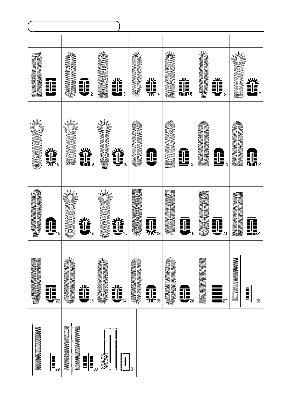
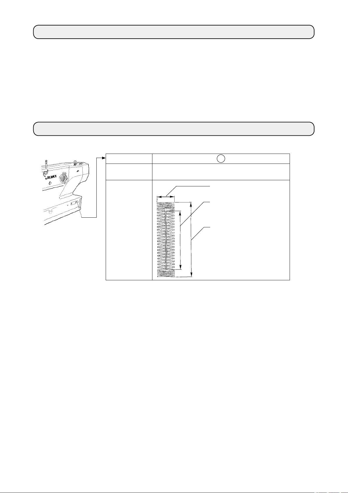
2. Standard sewing shape list
(1) Square type (2) Round type
PANEL
DISPLAY
(8) Eyelet radial
type
PANEL
DISPLAY
(15) Semilunar
taper bar-tacking
type
(9) Eyelet straight
bar-tacking type
(16) Eyelet semi-
PANEL
DISPLAY
PANEL
DISPLAY
lunar type
(3) Radial square
type
PANEL
DISPLAY
(10) Eyelet taper
bar-tacking type
PANEL
DISPLAY
(17) Eyelet round
type
(4) Radial type
PANEL
DISPLAY
(11) Semilunar
type
PANEL
DISPLAY
(18) Square radi-
al type
(5) Radial straight
bar-tacking type
PANEL
DISPLAY
(12) Round
square type
PANEL
DISPLAY
(19) Square
semilunar type
(6) Radial taper
bar-tacking type
PANEL
DISPLAY
(13) Semilunar
square type
PANEL
DISPLAY
(20) Square
round type
(7) Eyelet square
type
PANEL
DISPLAY
(14) Semilunar
straight bar-tack-
ing type
PANEL
DISPLAY
(21) Square
straight bar-tack-
ing type
PANEL
DISPLAY
(22) Square taper
bar-tacking type
PANEL
DISPLAY
(29) Bar-tacking,
left cut
PANEL
DISPLAY
PANEL
DISPLAY
(23) Radial semi-
lunar type
PANEL
DISPLAY
(30) Bar-tacking,
center cut
PANEL
DISPLAY
PANEL
DISPLAY
(24) Radial round
type
PANEL
DISPLAY
(31) Basting + Cloth
cutting knife
PANEL
DISPLAY
PANEL
DISPLAY
(25) Semilunar
radial type
PANEL
DISPLAY
PANEL
DISPLAY
(26) Semilunar
round type
PANEL
DISPLAY
PANEL
DISPLAY
(27) Bar-tacking
PANEL
DISPLAY
PANEL
DISPLAY
(28) Bar-tacking,
right cut
PANEL
DISPLAY
– 3 –
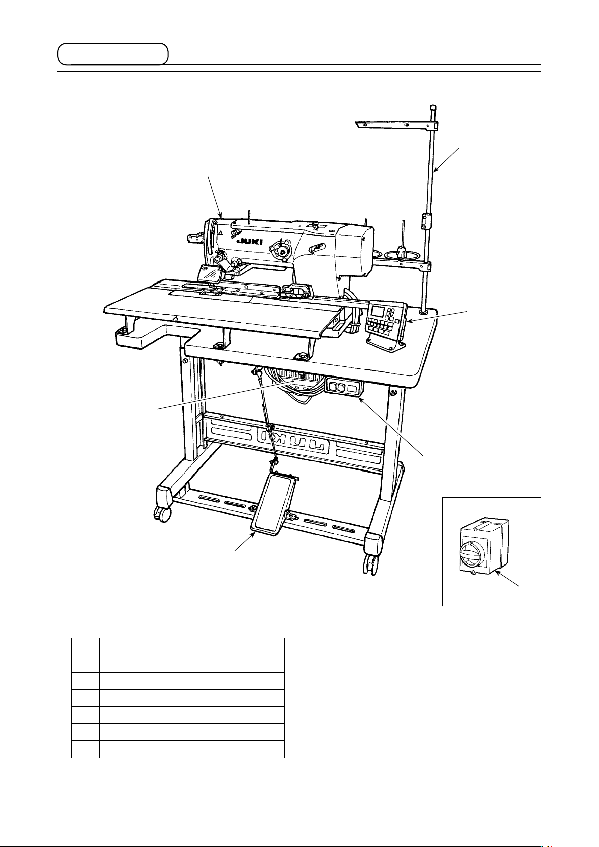
3. Conguration
❻
❷
❸
❹
❺
LBH-1796AN consists of the following components.
Power switch
❶
Machine head (LBH-1796AN)
❷
Operation panel
❸
Control box (MC-602)
❹
Presser lifting and starting pedal
❺
Thread stand device
❻
Power switch (EU type)
❼
❶
❼
– 4 –
III. INSTALLATION
WARNING :
To prevent possible accidents caused by the fall of the sewing machine, perform the work by two
persons or more when the machine is moved.
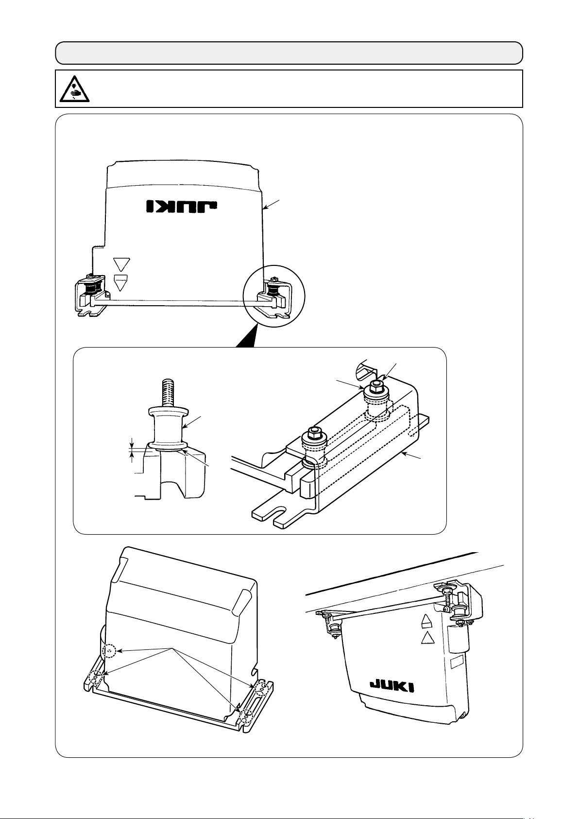
(1) Preparation for assembly of the control box
❶
1) Fix toothed washers ❷ and rubber cushions ❸ on control box ❶. (At four locations)
* Tighten the toothed washers so that their
height becomes 0.8 mm.
2) Fix control box mounting plate ❹ with plain
washers ❺ and nuts ❼. (At four locations)
* Fix the mounting plate while tting the
screw in the U-groove in the mounting
plate.
0.8 mm
❸
❷
❼
❺
❹
At four locations
– 5 –
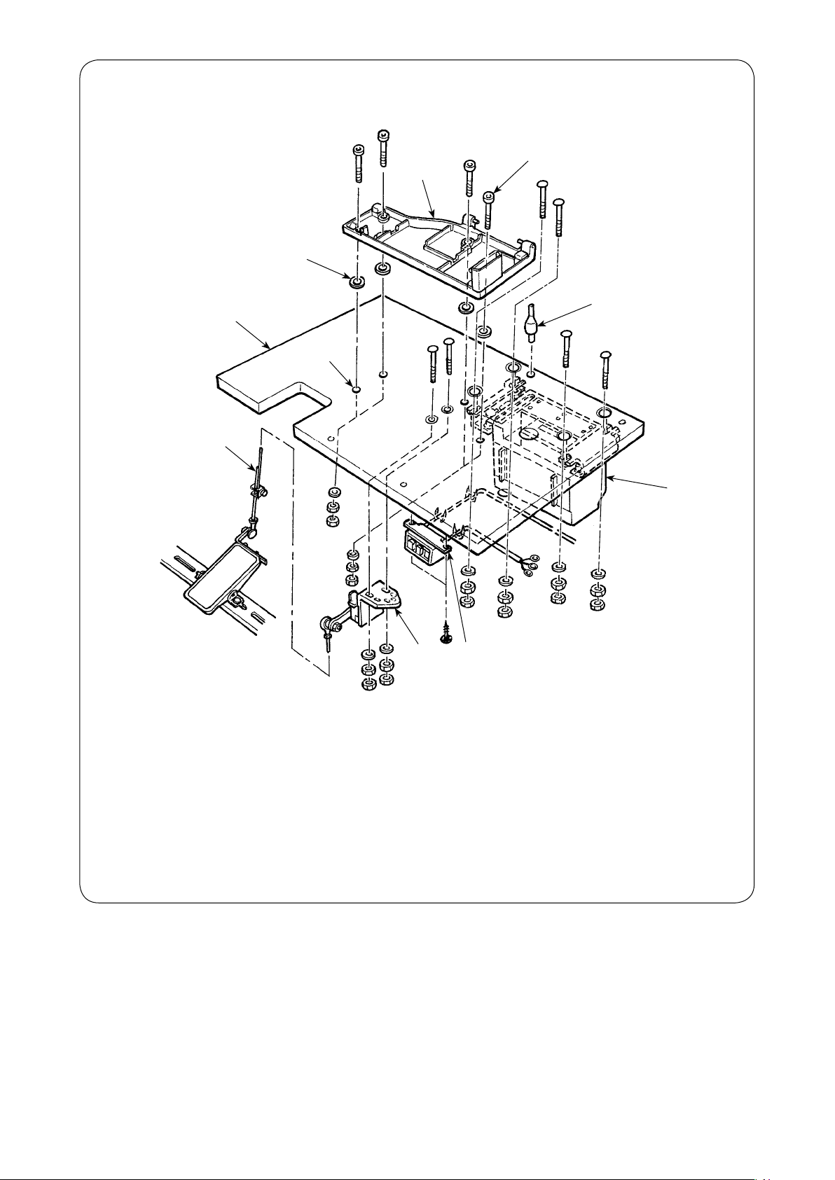
(2) Set-up of the table
❷
❺
❻
❼
❾
❽
❶
❹
1) Fix control box ❶, power switch ❸ and pedal sensor ❹ on table ❷.
2) Fix power switch ❸ with a staple.
3) Pass four bed base xed screws ❺ through bed base ❻.
4) Set rubber cushions ❼ to holes ❽ (4 places) for xing bed base and x bed base ❻.
5) Fix head support bar ❾ on table ❷.
6) Place the main unit of the sewing machine on bed base ❻. Then, connect the pedal and pedal
sensor ❹ with connecting rod supplied with the unit.
❸
– 6 –
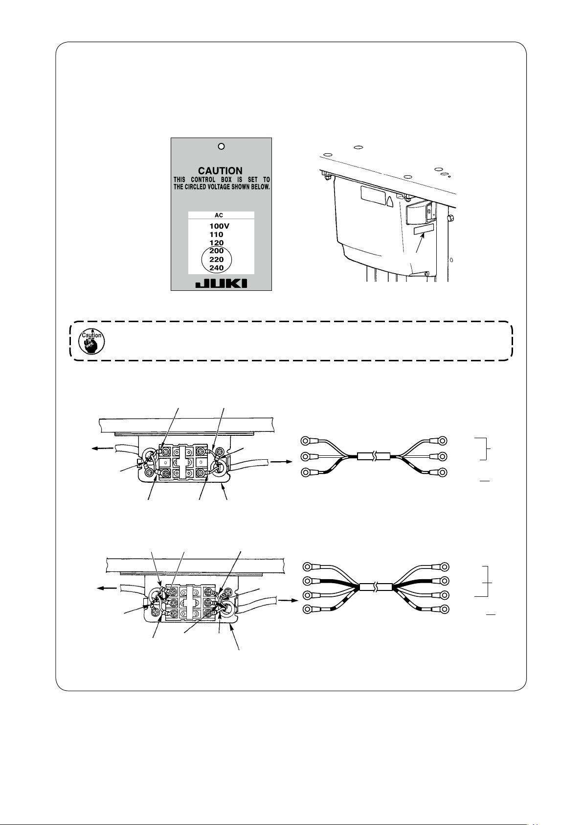
(3) Connecting the power source cord
• Connecting the power cable
Voltage specications are shown on the power indication tag attached on the power cable and on the
rating plate adhered on the power box. Connect the cable which matches the specications.
Power indication tag
Rating plate
(For example: In the
case of 200V)
Never use under the wrong voltage and phase.
• Connecting single phase 220V, 230V and 240V
Table
Control box
Green/Yellow
Light blue
Brown
Light blue
Brown
Green/Yellow
Plug
Power switch
• Connecting three phase 200V, 220V, 230V and 240V
White
Green/Yellow
Plug
Red
Power switch
Table
Control box
Green/Yellow
White Black
Red
Black
Power source cord
Power source cord
Light
blue
Brown
Green/
Yellow
White
Black
Red
Green/
Yellow
AC
220 V
-240 V
GND
AC
200 V
-240 V
GND
– 7 –
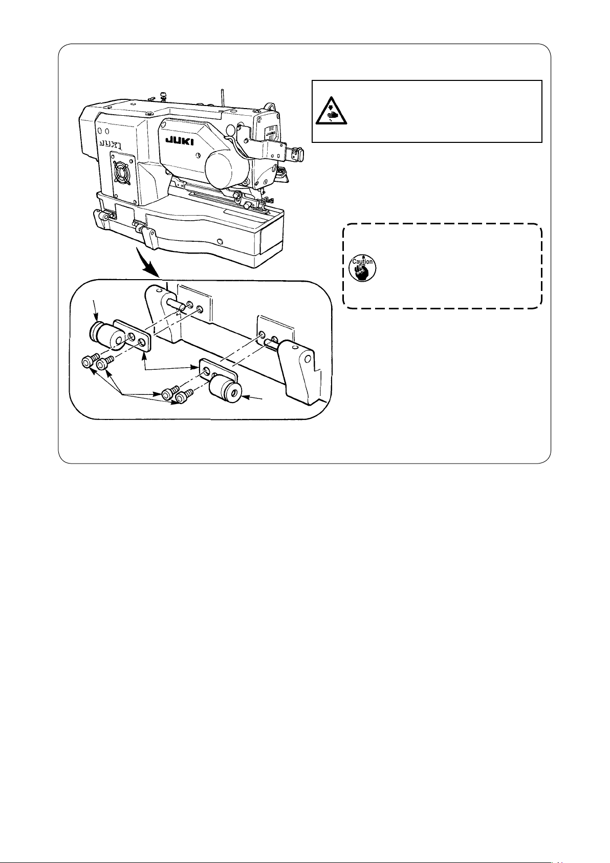
(4) Installing the sewing machine main unit
WARNING :
To prevent possible accidents caused by
the fall of the sewing machine, perform the
work by two persons or more when the
machine is moved.
-1
❷
(rubber)
❸
❶
-2
❷
(metal)
Place hinge plates ❶ and shaft bearings
-1 (rubber) and ❷-2 (metal) in two places
on the head base and x the hinge plates to
the machine head with setscrews ❸ in two
places.
When the rubber hinge and
metal tting hinge are installed
in reverse order, it is dangerous since the sewing machine
shakes when it is tilted. So, be
careful.
❷
– 8 –
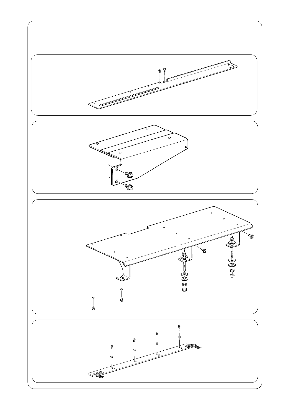
(5)
Preparation for installation of the feed plate, sub tables and positioning gauge
The parts listed below should be prepared in order to install the feed plate, sub tables and positioning
gauge on the machine head.
Feed plate
Two setscrews
・
Sub table B
Two setscrews
・
Sub table A
(To be used for fastening the sub
table A to the machine head)
Two setscrews
・
(To be used for fastening
the sub table A to the
sub table B)
Two setscrews
・
(To be used for fastening the sub
table A to the table)
Two setscrews
・
Four washers
・
Two pieces of rubber
・
Four nuts
・
Positioning gauge
Four setscrews
・
Four washers
・
– 9 –
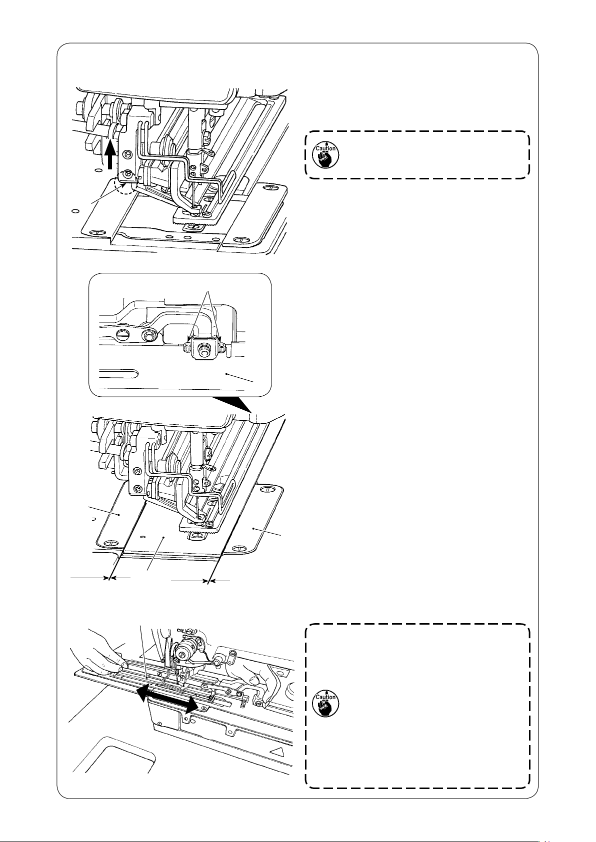
(6) Installing the feed plate
❶
1) Holding section ❶, lift up the presser foot and
place feed plate ❷, which is supplied with the
unit, in position.
Wipe the grease (for rust prevention)
off the top surface of the bed. Then,
attach the feed plate.
❹
0.1 mm
❷
❷
0.1 mm
❸
❷
2) Temporarily put two accessory setscrews ❸
into the corresponding tapped holes.
3) Adjust so that an equal lateral clearances (0.1
mm) is provided respectively between right and
left throat plate bases ❹ and feed plate ❷.
4) Tighten setscrews ❸.
5) Lower the presser foot. Then, move feed plate
back and forth to conrm that the feed plate
❹
❷
can be moved smoothly. (with a force of 30 N
or less).
If feed plate ❷ comes in contact with throat
plate base cover ❹ when moving the former
back and forth, loosen setscrews ❸ and re-position feed plate ❷ appropriately.
1.
Be careful not to place your hand under the presser foot when lowering it.
2. Be aware that the feed mechanism
can lose synchronism if the feed
plate cannot be moved smoothly
due to a hitch or an irregular torque.
3. If the feed plate is moved forward
again when the scissors has projected to reach to thread trimming
position, the feed plate can overpass the closing cam to cause the
sewing machine to lock.
– 10 –
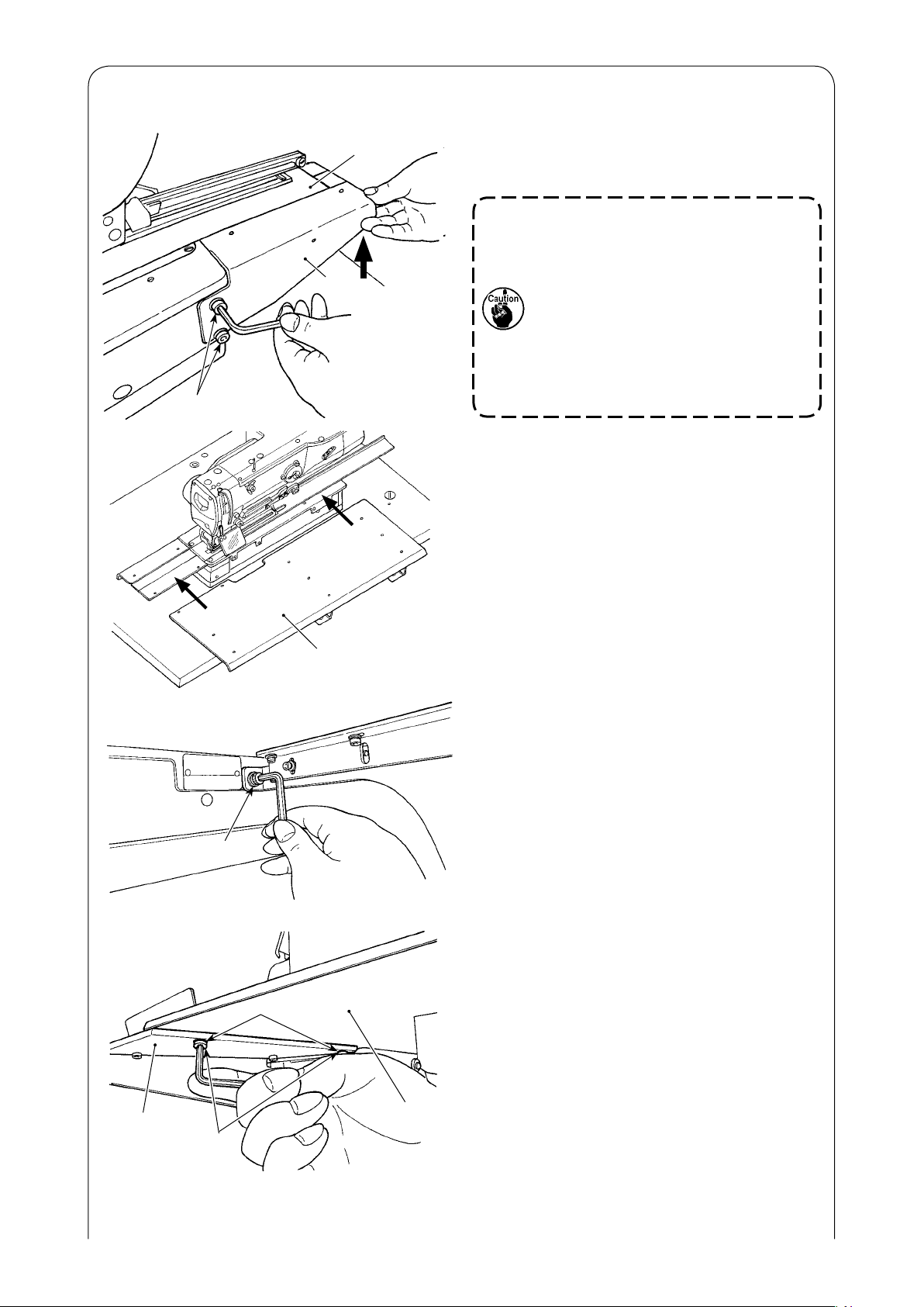
(7) Installing the sub tables
❷
❸
❶
Lightly press
against the
feed plate
1) Move feed plate ❶ forward. Lightly press sub
table B ❷, supplied with the unit. Then, temporarily tighten setscrews ❸.
If the sub table B does not support
the feed plate when the latter moves
forward, the presser foot fails to hold
the material securely, causing stitch
skipping and thread breakage.
On the other hand, if the sub table B
is excessively pressed against the
feed plate, the feed mechanism can
lose synchronism due to an excessive load when it is moved forward.
2) Fit sub table A ❹, supplied with the unit, to the
bed and sub table B ❷.
❺
❹
3) Temporarily fix sub table A ❹, supplied with
the unit, on the machine head with two setscrews ❺.
4) Join sub table A ❹ to sub table B ❷ with two
setscrews ❻ and two washers ❼.
❼
❷
❻
❹
5) Firmly tighten all the setscrews which have
been temporarily tightened.
– 11 –
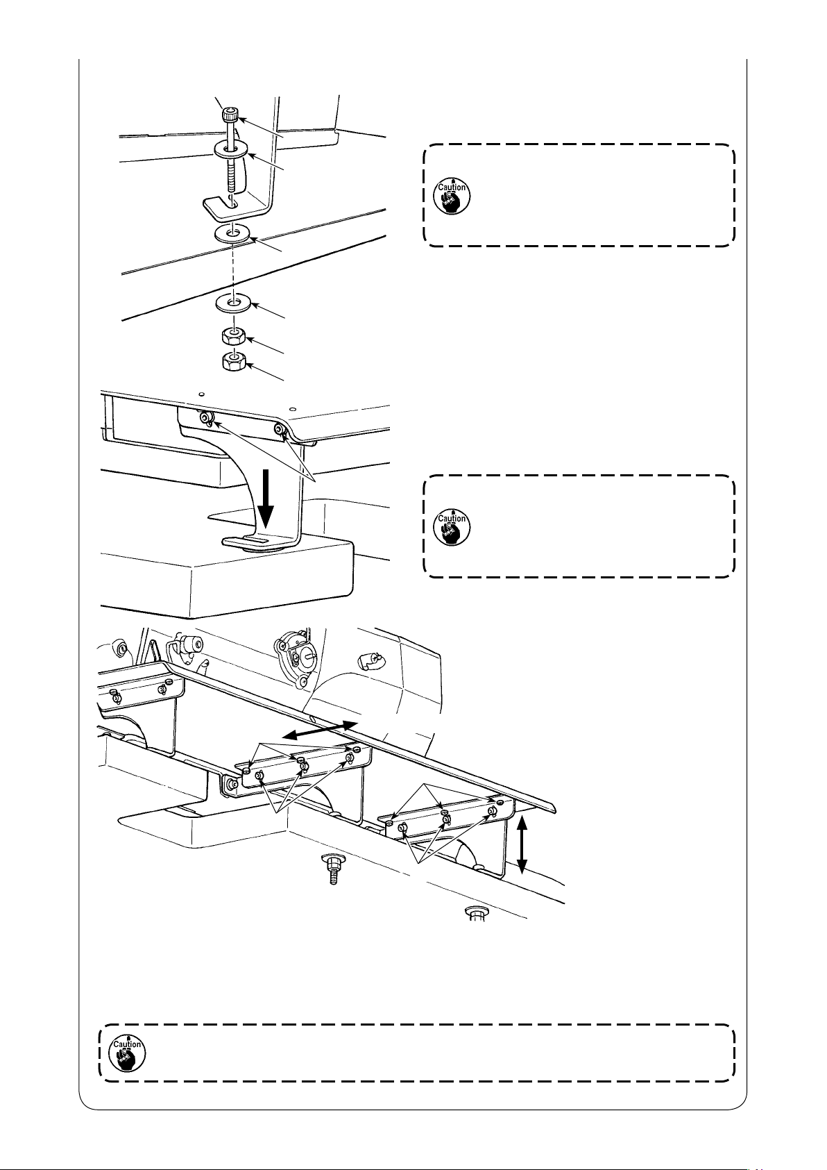
❾
❼
❽
❼
6) Move the feed plate back and forth to check
that it can be moved smoothly without being
hitched along the sub tables.
If the feed plate and the sub tables are
joined in the state where they interfere with each other, an extra load can
be produced. In this case, the feed
mechanism can lose synchronism.
7) Mount the base of the sub table A on the table
with two sets of setscrew ❾ and nut with
washer ❼ and a piece of rubber ❽ placed between them.
8) Fix the support metal plate which supports
the sub table A with two setscrews $11$ while
pressing it in the direction of the arrow so that it
project the table by 0.1 to 1 mm.
If the sub table A is not closely tted
to the table and not applied with an
adequate pressure, the sub table A
can vibrate heavily at a sewing speed
around 2,000 sti/min to make a noise.
Longitudinal direction
Vertical direction
9) In the case the longitudinal mounting direction of the sub table A is not correct, loosen six setscrews
and re-position the sub table A. Then, x it in the correct position.
In the case the vertical mounting direction of sub table A is not correct, loosen six setscrews and
re-position sub table A. Then, x it in the correct position.
If the sub table A is tted excessively near the bed, it can come in contact with the feed
plate causing the feed mechanism to lose synchronism.
– 12 –
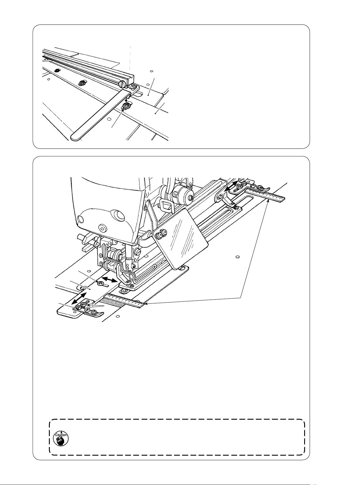
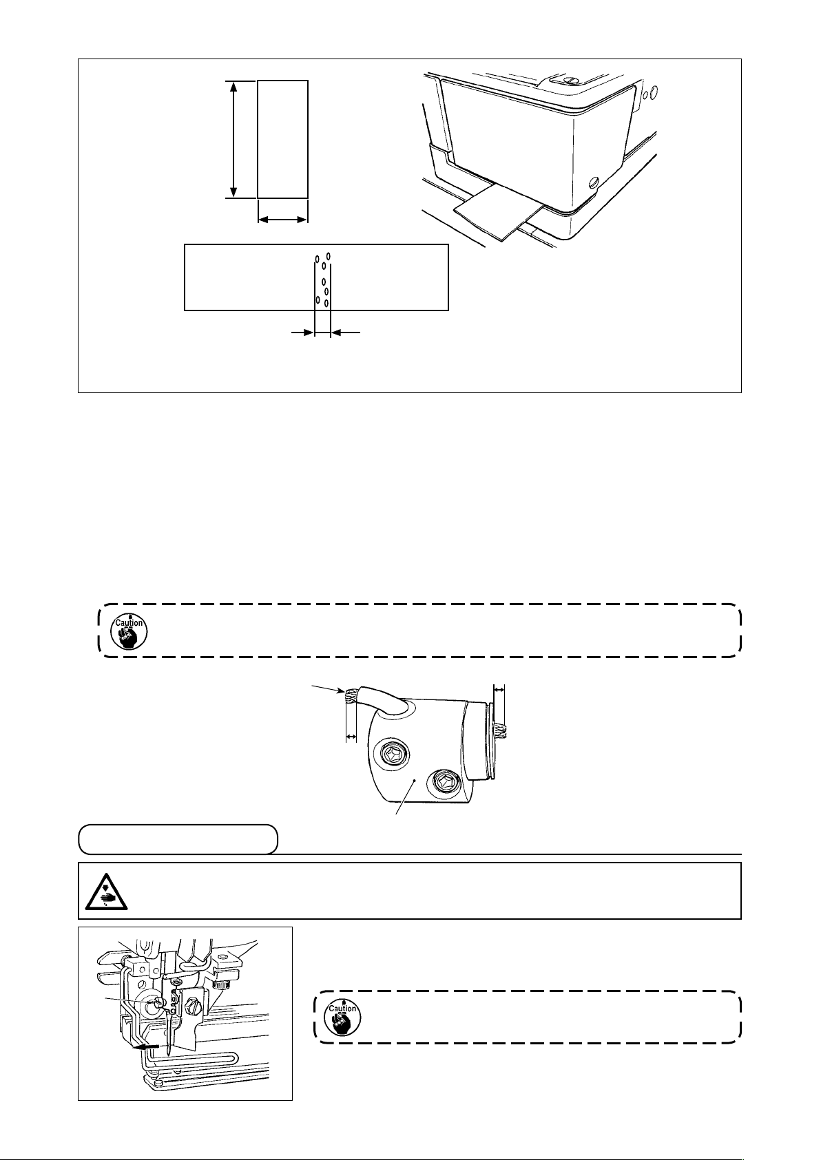
(8) Temporarily installing the positioning gauge
1) Move feed plate ❶ forward.
2) Temporarily fix positioning gauge ❹ on the
❶
❹
❷❸
feed plate with setscrews ❷ and washers ❸
(four pieces each).
(9) Adjusting the positioning gauge
❷
❶
❹
1) Loosen setscrews ❷ (at four locations) of positioning gauge ❶.
2) Fit a ruler respectively at the front side and the far side of positioning gauge ❶ to determine its
position.
3) Once the position of the positioning gauge is determined, tighten three setscrews ❷.
4) Loosen setscrews ❸ of buttonhole interval gauge ❹.
5) Move buttonhole interval gauge ❹ to obtain a desired buttonhole interval.
6) Once the position of the buttonhole interval gauge is determined, tighten setscrews ❸.
(If the positioning gauge is not necessary, it should be removed.)
Adjustable range of the positioning gauge (a distance from the center of the knife slot)
13 mm - 23 mm
1. If setscrew ❷ is tightened with a tightening torque of 2.0 N•m or more, the screw
threads can be damaged. Be careful not to tighten the setscrews excessively.
2. In the case the adjustment range of the positioning gauge is adjusted to less than
13 mm, the gauge can tilt.
❸
Rulers or the like
– 13 –
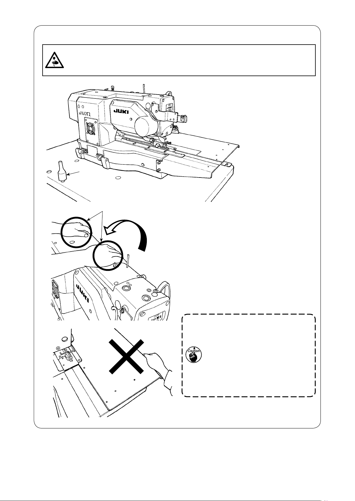
(10) Tilting the sewing machine head
WARNING :
When tilting/raising the sewing machine head, perform the work so as not to allow your ngers
to be caught in the machine. In addition, to avoid possible accidents caused by abrupt start of
the machine, turn OFF the power to the machine before starting the work.
❶
A
1) Turn the thread stand unit to a position where
it is not an obstacle to the conduct of the following procedure.
2) Whenever you tilt the machine head, go
around behind the sewing machine and check
to make sure that the top cover and the motor cover are securely fixed. Then, holding
A
sections of the machine head with both
hands, carefully tilt the machine head until the
machine head comes in contact with machine
head supporting rod ❶.
– 14 –
1. Make sure that sewing machine
head support bar ❶ is placed on
the table before tilting the sewing
machine.
2. To protect fall-down, be sure to
tilt the sewing machine in a level
place.
3. Never tilt the machine head while
holding it by the sub table.
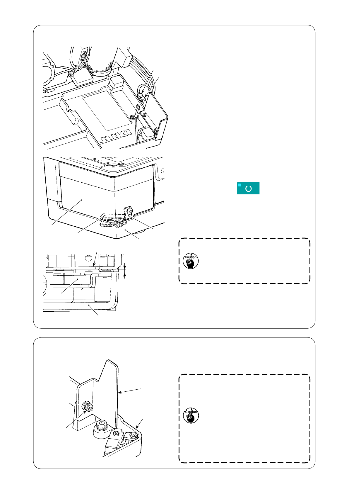
(11) Connecting the machine head tilt detector
1) Connect machine head tilt detector ❶ with
connector ❷ located on the machine head
side.
2) Adjust detecting plate ❹ so that a clearance
of 1.2 to 2.5 mm is provided between tilt detection sensor ❸ and detecting plate ❹.
Press READY key to conrm that no
error occurs.
In addition, open and close hook cover ❺ to
conrm that detecting plate ❹ does not interfere with bed base ❻.
❺
❸
❷
❶
❹
❻
❹
1.2 to 2.5 mm
If detecting plate ❹ is not properly
adjusted, E302 (machine head tilt error or hook cover open error) can occur to disable the normal operation
of the sewing machine.
❸
❻
(12) Installing the hook oil shield plate
❶
❸
❷
Install hook oil shield plate ❶ onto bed base ❸
with setscrew ❷.
Attach hook oil shield plate ❶ to the
bed base with the sewing machine
raised.
In addition, check to be sure that the
sewing machine does not interfere
with hook oil shield plate ❶ when
tilting/raising the former.
Adjust the mounting of the hook oil
shield plate ❶ to prevent scattered
from the gap between the bed and
cover pot.
– 15 –
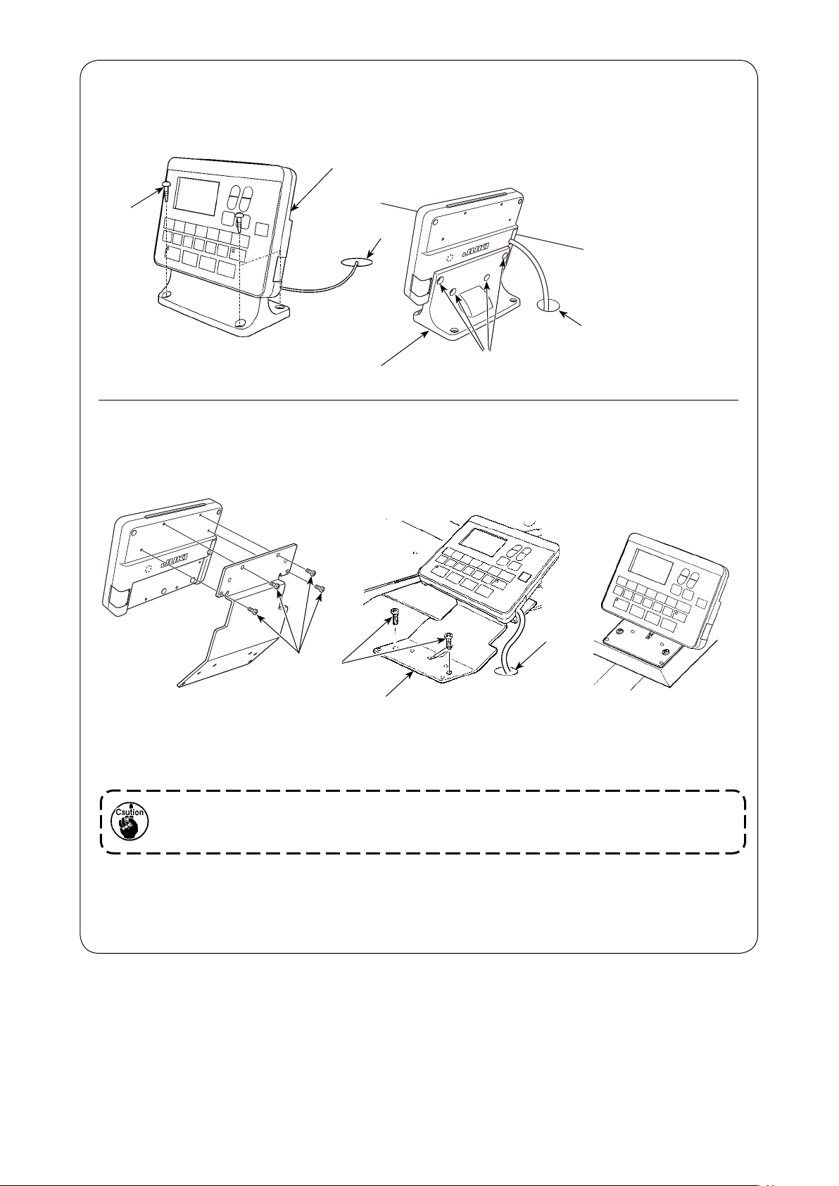
(13) Installing the operation panel
(Standard installation)
Fix operation panel asm. ❶ on the table with four wood
❶
❷
Resin panel base
(Installation using the accessory plate)
If the operation panel comes in contact with the sewing material, the accessory plate should be used to
prevent the contact.
screws ❷. Pass the cable through hole ❸ in the table.
❸
❸
❹
❸
❻
❼
❺
1) Remove four tapping screw ❹ from the resin panel base to detach the operation panel.
2) Install panel mounting plate ❺, supplied with the unit, with four accessory setscrews ❻ instead of
the tapping screws.
If panel mounting plate ❺ is installed with tapping screws ❹ which are removed from
the resin panel base, the panel PCB can be damaged.
3) Fix panel mounting plate ❺ on the table with two wood screws ❼. Pass the cable through hole ❸
in the table.
– 16 –
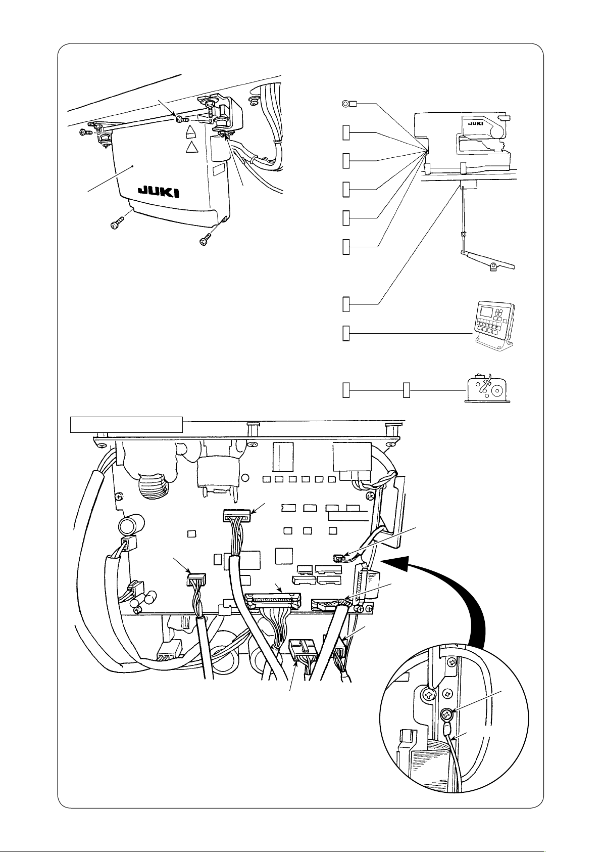
(14) Connecting the cords
❷
❶
❹
1) Loosen four setscrews ❷ of control box cover ❶. Remove control box cover ❶.
2) Connect the cord to the connector on the
MAIN PCB as illustrated in the gure below.
3) Fix the earth cord with setscrew ❸.
4) Install control box cover ❶.
5) Fix control box cover with the washers,
spring washers and nuts ❹.
Earth cord
CN15
CN17
CN32
CN40
CN49
CN39
CN34
Sewing machine head
Operation panel
Electric bobbin winding device (optional)
MAIN circuit board
CN40
MAIN-INT C
CN32
MAIN-INT B
CN34
Panel
CN44
CN39
Pedal
CN49
MAIN-INT A
CN15
Main motor encoder
CN17
Main motor cord
– 17 –
❸
Earth cord
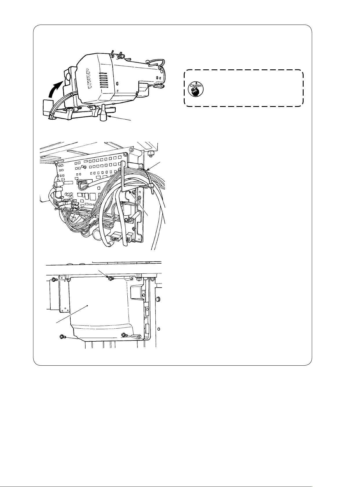
(15) Managing the cord
❶
❸
1) Slowly tilting the sewing machine, check
that the cords are not forcibly pulled.
When you tilt the sewing machine, make sure that the sewing
machine head support bar ❶ is
placed on the table.
2) Bring the cords under the table into the
control box.
3) Put the cord brought into the control box
through cord exit plate ❷ and fix cable
clip band ❸.
❹
❺
❷
4) Install control box lid ❹ with four setscrews ❺.
– 18 –
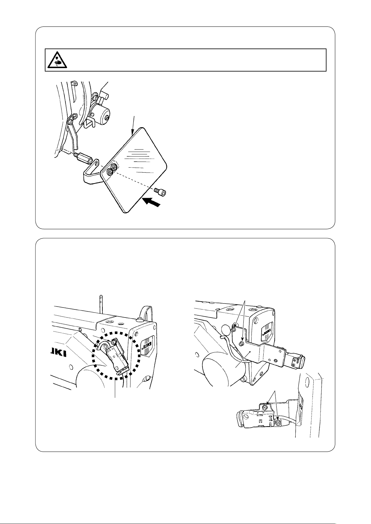
(16) Installing the eye protection cover
WARNING :
Be sure to attach this cover to protect the eyes from the disperse of needle breakage.
❶
Operator
Be sure to install and use eye protection cover ❶
and use the sewing machine.
(17) Fixing the temporary stop switch
The temporary stop switch has been factory-set in state A at the time of shipment. Loosen setscrews
and x mounting plate ❸ with setscrews ❶. Then, x the switch on mounting plate ❸ with acces-
❶
sory setscrews ❷.
❶
❶
➡
❸
❷
A
– 19 –
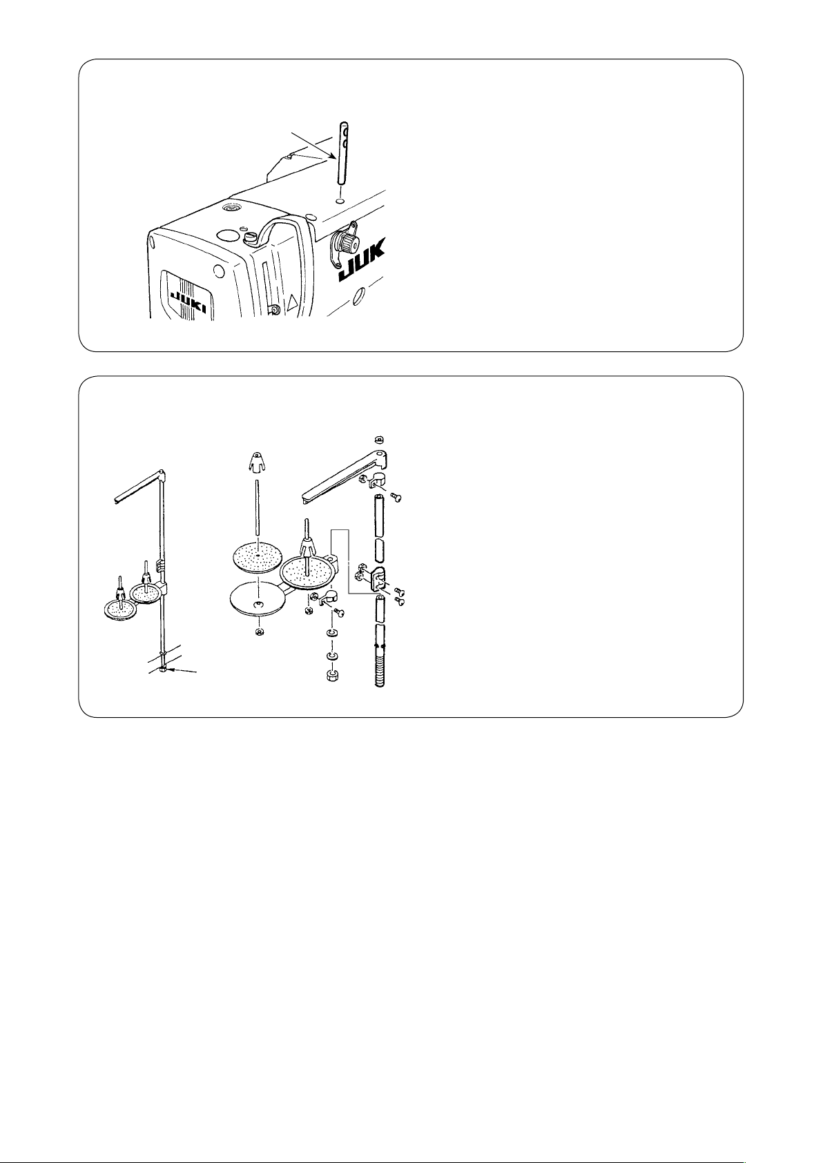
(18) Thread guide rod
Thread guide rod
(19) Installing the thread stand
Securely t the thread guide rod so that two side
holes in the thread guide rod face the thread
guide.
1) Assemble the thread stand, and set it in the
hole in the top right corner of the machine
table.
2) Tighten locknut ❶ to x the thread stand.
❶
– 20 –
IV. PREPARATION BEFORE OPERATION
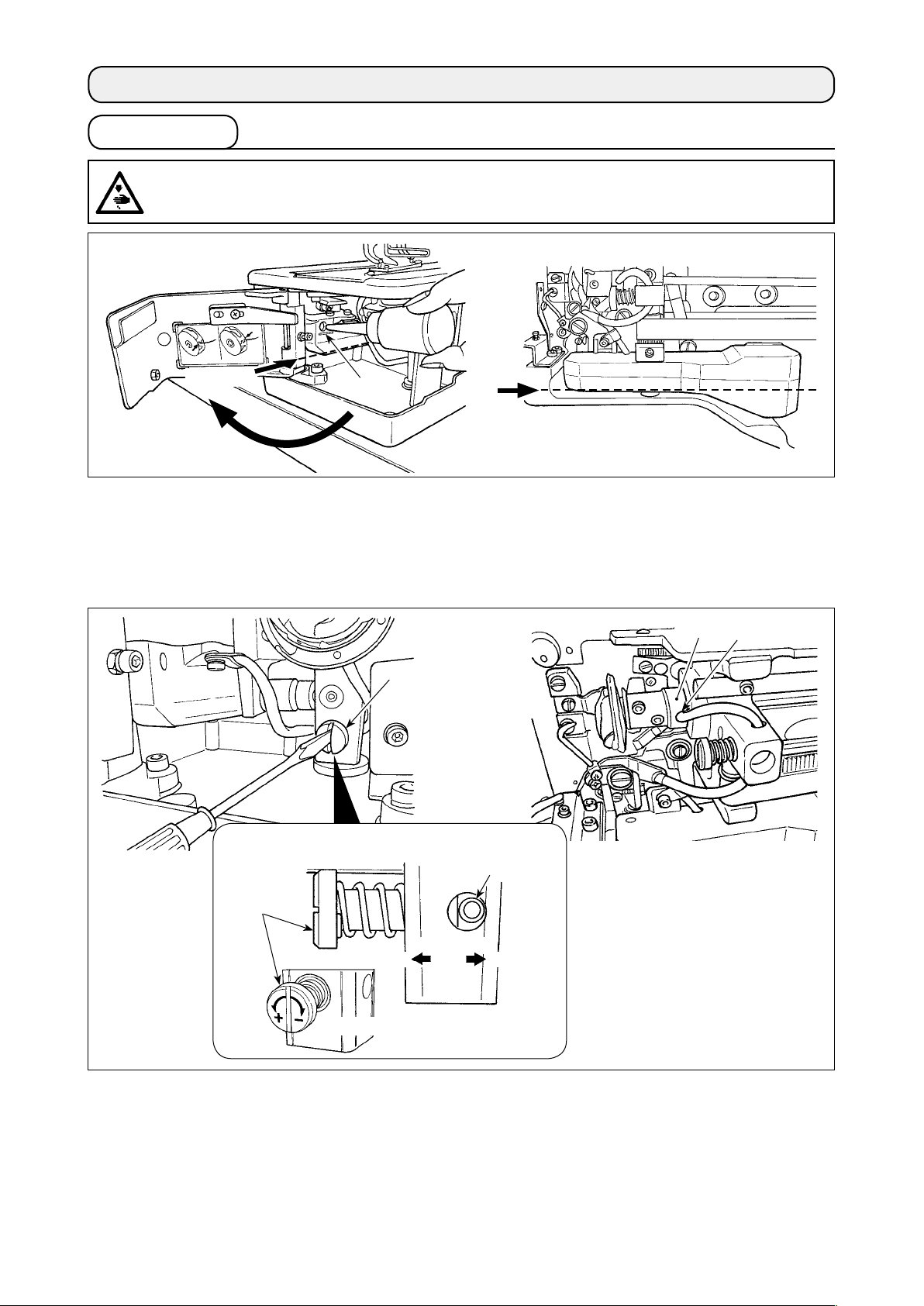
1. Lubrication
WARNING :
To protect against possible personal injury due to abrupt start of the machine, be sure to start the following work after turning the power off and ascertaining that the motor is at rest.
Front side
❶
Front
side
1) Lubricating oil to oiling tank
○ Fill the oiling tank with JUKI New Defrix Oil No.1 up to the level indicated by “MAX” ❶. When supply-
ing oil to the oil tank through the lubricating hole, take care not to allow dust to enter the oil tank.
○ Supply oil in the case the oil cannot be visually observed from the front side of the oil tank.
❸
❹
❷
Detailed diagram of oil amount adjusting section
Oil pipe
❷
Increase
Increase
Oil amount
Decrease
Decrease
2) Adjusting the lubrication for the sewing hook
○ The amount of oil is adjusted with oil amount adjusting screw ❷.
○ Amount of supplied oil is reduced when turning the screws ❷ clockwise.
○ When you rst operate your sewing machine after set-up or after an extended period of disuse, re-
move the bobbin case and apply a few drops of oil to the hook race. In addition, apply a few drops oil
from oiling hole ❹ in hook driving shaft front metal ❸ to soak the inside felt in oil.
– 21 –
100 mm
40 mm
2 to 5 mm
* The adequate oil quantity is achieved when the oil spots are made on paper within a
range of 2 to 5 mm in width (oil spots should not be in the form of lines).
3) How to check the hook oil quantity
1. In preparation for checking the hook oil quantity, cut a sheet of paper to make a piece of paper size of
which is approximately 40 mm × 100 mm.
2. After the adjustment of the oil quantity, start the sewing machine at a high speed (3,600 sti/min) by
100 times or more.
3. Insert the piece of paper prepared in Step 1 into the clearance provided between the hook cover and
the bed base so that it is placed near the underside of the hook.
As a guide, insert the paper until it comes in contact with the hook oil shield.
4. Supporting the paper with hand, run the sewing machine by ve cycles using the standard pattern (3,600
sti/min) and check the splashing oil quantity.
In the case the oil quantity is too much even after the oil controlling screw is fully tight-
ened, remove the hook shaft coupling and cut off the excess of oil wick.
Oil wick
Approximately 0.5 mm
Hook shaft coupling
Approximately 0.5 mm
2. Inserting the needle
WARNING :
To protect against possible personal injury due to abrupt start of the machine, be sure to start the following work after turning the power off and ascertaining that the motor is at rest.
Hold needle with its recessed part facing toward the operator side A,
insert the needle fully into the needle clamping hole, and tighten needle setscrew ❶. Use a DP×5 (#11J, #14J).
❶
When attaching the needle, turn OFF the power to the
motor.
A
– 22 –
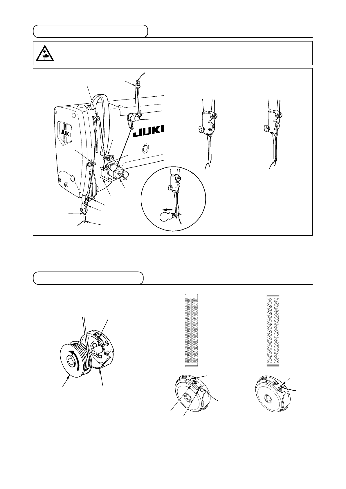
3. Threading the needle-thread
WARNING :
To protect against possible personal injury due to abrupt start of the machine, be sure to start the following work after turning the power off and ascertaining that the motor is at rest.
❼
❶
Cotton thread, spun thread
Synthetic lament thread
❷
❻
❽
❹
❸
❺
❾
Pass the needle thread in the order ❶ to as shown in the gures.
The threading can be done easily by using the needle threader supplied with the machine.
Change the thread guide threading method according to the thread to be used.
4. Threading the bobbin case
Whip stitchPurl stitch
❶
❷
Bobbin
Bobbin case
❸
❹
Rotating direction of bobbin and threading
1) Fit the bobbin so that it rotates in the direction of the arrow.
2) Pass the thread through thread slit ❶, then through under the tension spring ❷, again through thread
slit ❸, and pull the thread from ❹.
3) Threading at ❹ for purl stitching is different from that for whip stitching. So, be careful.
❹
– 23 –
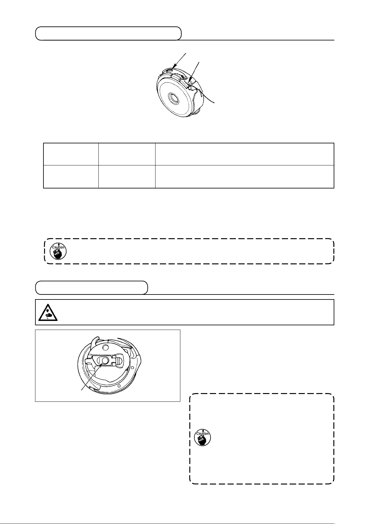
5. Adjusting the bobbin thread tension
❷
❶
Adjust the bobbin thread tension as given below when the bobbin thread is pulled up at the position where
thread slit ❶ of bobbin case comes up.
To such an extent that bobbin case quietly comes down when holding
Purl stitch
Whip stitch
Turning tension adjust screw ❷ clockwise will increase bobbin thread tension, and turning it counterclockwise will decrease the tension.
Adjust the bobbin thread tension to lower for synthetic lament thread, and to higher for spun thread. The
thread tension is higher by approximately 0.05N when the bobbin case is set to the hook since idle-prevention spring is provided.
0.05 to 0.15N
0.15 to 0.3N
thread end coming from bobbin case and shaking it quietly up and
down.
To such an extent that bobbin case barely comes down when holding thread end coming from bobbin case and shaking it somewhat
strongly.
When bobbin thread tension is adjusted, check the needle thread tension setting of the
memory switch. (Refer to "V-22. Memory switch data list" p.64.)
6. Installation of bobbin case
WARNING :
To protect against possible personal injury due to abrupt start of the machine, be sure to start the following work after turning the power off and ascertaining that the motor is at rest.
1) Lift up and hold bobbin case latch lever between
two ngers.
2) Push the bobbin case into the hook so that it is
supported by the hook shaft ❶ and then snap in
the latch lever.
Press the bobbin case until the predetermined
position is reached, and it will click.
❶
1. If the bobbin case is out of the pre-
determined position, it can jump out
from the hook to cause the needle
thread to tangle on the hook shaft.
Check to be sure that the bobbin
case is properly installed in the correct position.
2. There is a difference in the shape of
bobbin case between the standard
hook and the dry one. They have
nothing in common with each other.
– 24 –
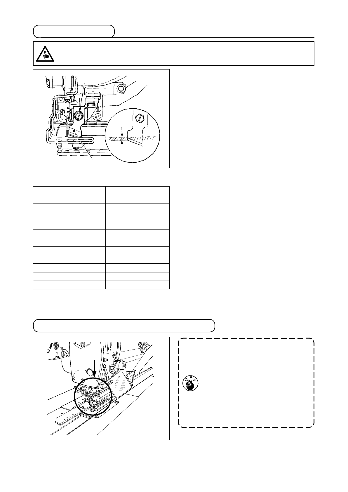
7. Installing the knife
WARNING :
To protect against possible personal injury due to abrupt start of the machine, be sure to start the following work after turning the power off and ascertaining that the motor is at rest.
❷
1 to 2 mm
❶
Inch → mm CONVERSION TABLE
Knife size Indication of mm
1/4 6.40
3/8 9.50
7/16 11.10
1/2 12.70
9/16 14.30
5/8 15.90
11/16 17.50
3/4 19.10
13/16 20.60
7/8 22.20
1 25.40
When replacing the knife with a new one, perform as
follows.
1) Knife ❶ can be easily removed together with the
washer when removing knife retaining screw ❷.
2) Lower the knife bar by hand. Now, push the knife
bar down so that the knife goes below the top
surface of the throat plate by 1 to 2 mm, as illustrated in the gure. In this state, place the washer and tighten the setscrew.
When the cloth cutting knife you have is indicated in
inch, set the cloth cutting length (knife size) in mm
using the inch → mm conversion table. (Refer to
12. Sewing data list" p.43
.)
"V-
8. Item to be checked before turning the power ON
If the work clamp foot is the lifted state
before turning the power ON, lower it
rstly and turn ON the power to the
sewing machine.
When lowering the work clamp, take
care not to place your hands near the
knife.
If the power is turned ON with the work
clamp raised and the READY key is
pressed, "E998 Work clamp deviation
error" can occur.
– 25 –
V. OPERATION OF THE SEWING MACHINE
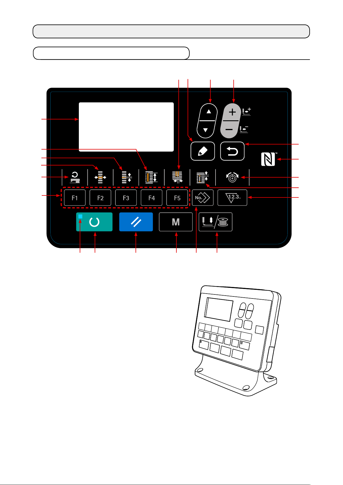
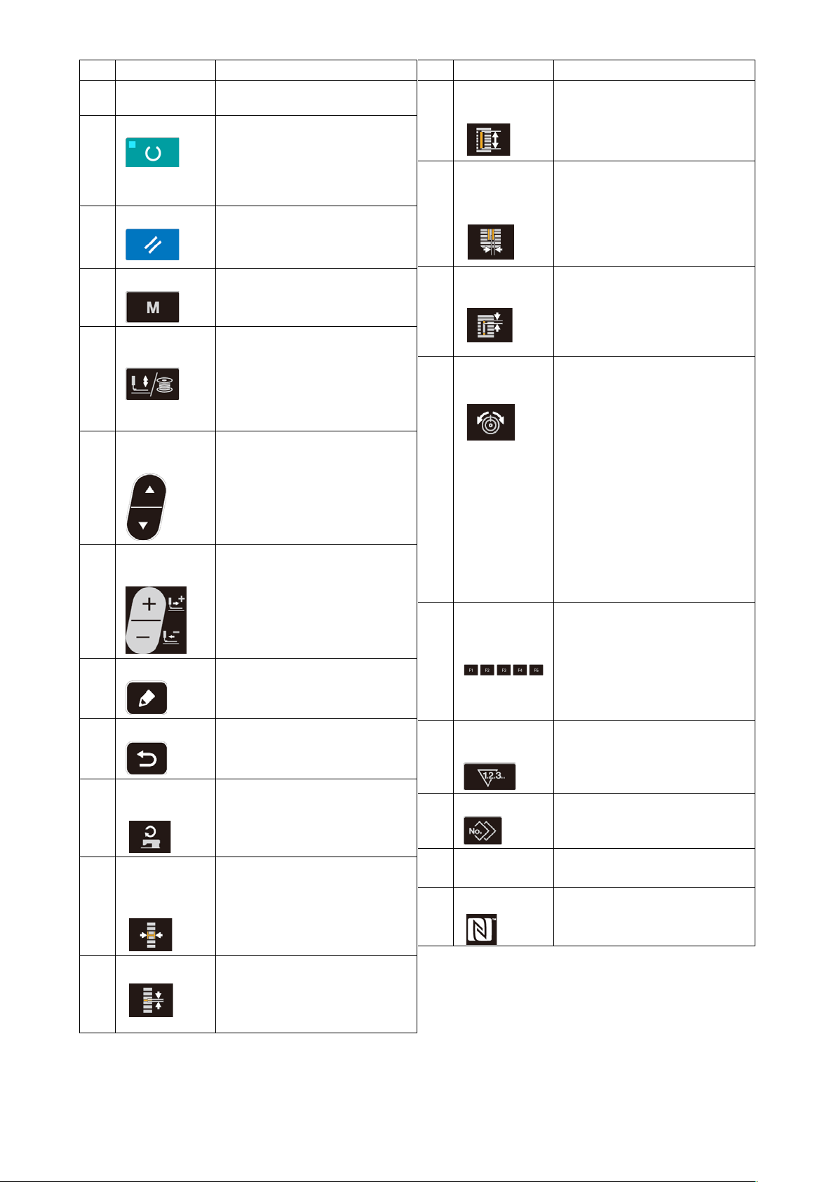
1. Explanation of the operation panel switch
❶
❽
❻
❼
❾
❷ ❺❹❸
– 26 –
No. NAME FUNCTION
LCD display Various data such as pattern No.,
❶
READY key Press this key when starting sew-
❷
RESET key Press this key when releasing
❸
MODE key This key is used for displaying the
❹
PRESSER and
❺
WINDER key
ITEM SELECT
❻
key
DATA
❼
CHANGE key
EDIT key This key is used to display the
❽
RETURN key This key is used to return the
❾
shape, etc. are displayed.
ing.
Every time this key is pressed,
change-over of sewing ready set
state and data set state can be
performed.
error, travelling the feed mechanism to its initial position, counter
resetting, etc.
mode screen.
This key lifts or lowers the presser. When the presser goes up,
the needle bar travels to the origin and when it comes down, the
needle bar travels to the right.
This key is pressed when performing bobbin winding.
This key is used to select the data
No. and other kinds of data.
This key is used to change the
pattern No. and other kinds of
data.
This key is used to move the feed
forward on a stitch-by-stitch basis.
edit screen, to select the item or
to display the detail screen.
screen to the previous one.
No. NAME FUNCTION
CLOTH CUT
LENGTH key
KNIFE
GROOVE
WIDTH key
CLEARANCE
key
THREAD TEN-
SION key
PARAMETER
REGISTRATION key
COUNTER
key
This key selects cloth cut length
display.
This key is used to select the
knife-groove width correction display.
Every time this key is pressed,
S003 (right) and S004 (left) are
displayed alternately.
This key selects clearance display.
Every time this key is pressed,
S022 (first clearance) and S023
(second clearance) are displayed
alternately.
This key is used to select the
thread tension display.
Every time this key is pressed,
the display item is changed over
as described below:
S052 Thread tension at the right
parallel section
S053 Thread tension at the left
parallel section (first cycle
of double stitching)
S054 Thread tension at the right
parallel section (first cycle
of double stitching)
S055 Thread tension at the first
bartacking section
S056 Thread tension at the sec-
ond bartacking section
This is a short cut key that parameter registration is available.
Registration of shortcut to setting
display of an optional pattern,
sewing parameter or adjustment
data is possible. For the setting
procedure, Refer to
parameter register key" p.52
This key selects counter display.
"V-15. Using
.
SEWING
SPEED key
OVEREDGING WIDTH
key
PITCH key
This key is used to display the parameter edit items related to the
sewing speed.
This key selects overedging width
display.
Every time this key is pressed,
S005 and S006 are displayed alternately.
This key selects pitch of parallel
section.
Every time this key is pressed,
S007 and S021 are displayed alternately.
– 27 –
COPY key Press this key when copying pat-
SET READY
LED
NFC mark Bring the tablet or smartphone
tern.
It lights up under the sewing
mode.
close to the NFC mark when
carrying out communication.

2. Basic operation of the sewing machine
1) Select the model of your sewing machine.
When you turn the power ON for the first time
after the purchase of your sewing machine, the
model confirmation screen is displayed. Press
READY key ❷ .
When Error E001 screen B is displayed, turn the
power OFF.
A
❷
B
* In the case the power-OFF screen C is dis-
played after the completion of procedure described in 1), turn the power OFF once. Then,
carry out the procedure described 1) again.
– 28 –
C

2) Selecting the language.
When you turn the power ON for the rst time
after the completion of procedure described in 1),
the language selection screen A is displayed.
Select the language to be displayed, then press
RETURN key ❾ .
If you terminate the language selection by pressing RETURN key
A
❾
language, the language selection
screen will be displayed every
time you turn ON the power to the
sewing machine.
without selecting the
3) Select the pattern No. you desire to
sew.
When you turn the power ON, the currently-selected pattern No. B and pattern data name C
are displayed.
When you desire to change it, press DATA
CHANGE key ❼ and select the No. you
desire to sew. When you purchase the sewing
machine, pattern No. 1 to 10 described in
10. Changing sewing data" p.40
registered. Select the pattern No. you desire to
sew from among these numbers. (The No. with
which the pattern has not been registered is not
displayed.)
have been
"V-
B C
❷
❾
❼
4) Set the sewing machine to sewing possible state.
When READY key ❷ is pressed, SET READY LED lights up to show that the sewing is en-
abled.
5) Start sewing.
Set the sewing product to the presser portion, and operate the pedal to start the sewing machine, and
sewing starts.
The pedal type of the sewing machine has been factory-set to the 1-pedal type at the time of shipment.
However, the pedal operation method can be selected from among four different ones. Select the operating procedure you desire and use the sewing machine.
→ Refer to
"V-3. How to use the pedal" p.30
.
– 29 –

3. How to use the pedal
For this sewing machine, the pedal operation method to be used can be selected from among the four
different ones. Select the operating procedure you desire for working efciency and use the sewing machine.
(1) Setting procedure of the pedal type
1) Call the pedal type setting parameter.
Keep MODE key ❹ held pressed for
three seconds under the input mode where SET
READY LED goes out. Then, the MEMORY
switch (level 2) is displayed on the menu.
Select the target item with ITEM SELECT key
and press EDIT key ❽ . Then, the
❻
memory switch (level 2) edit screen A is displayed.
When the pedal type selection parameter
is not displayed, press ITEM SELECT key ❻
to select the pedal type.
2) Select the pedal type.
A B
❼❻❽
❹
Press DATA CHANGE key ❼ and the pic-
ture is changed as shown in the illustration below.
Select the pedal type B you desire.
2-pedal
1-pedal
(Without intermediate
position)
1-pedal
(With intermediate
position)
1-pedal
(With a depress on the
back part of the pedal)
– 30 –

3) PK pedal (to be used for operating the sewing machine in a standing position)
PK pedals below can be connected to the machine.
Name of part JUKI Part No. Remarks
PK-51 GPK510010B0 2-pedal type for standing work
PK-57 GPK570010B0 1-pedal 2-step type for standing work
When using PK pedal, the relay cord below is necessary.
Name of part JUKI Part No. Remarks
PK pedal relay cord (asm.) 40003493 Common to PK-51 and PK-57
1. Connecting procedure
(1) Remove connector CN41 (white • 6P) of MAIN board in the control box. The connector which has
been removed is the connector of the pedal provided as standard. Use it in case of need.
(2) Connect connector (CN41) of the relay cord to CN41.
(3) Connect connector (CN71) of the relay cord with the connector of PK pedal. In case of PK-51, the
connection is completed with the work above. Besides, in case of PK-57, the earth line protrudes at
the connector section. However, it is not necessary to connect it.
(4) In case of PK-57, remove the cover and perform the change of connection of the micro switch locat-
ed inside the pedal. Change the connection of micro switch (upper side) in which the switch button is
pressed when the pedal is set to free from NC (normal close) to NO (normal open).
2. When using PK pedal, perform the following operation.
(1) Enable to select the PK pedal.
Display the mode screen while turning ON the DIP switch 2 of the panel board.
(2) Select to PK pedal.
Select PK pedal by K001 (pedal selection) of memory switch level 2 setting screen.
Display Pedal selection
Select PK-51
Select PK-57
– 31 –

(2) Explanation of pedal motion
2-pedal type
Initial position
Presser : Intermediate
position ② or Cloth
setting position
③
1) Setting of
sewing product
Presser goes up as
high as the pedal toe
down amount of the
left side pedal.
2) Start of Sewing
Sewing starts when
the right side pedal is
depressed.
3) End of sewing
Presser automatically
goes up to Intermediate position ②.
1-pedal
(Without intermediate
position)
Initial position
Presser : Maximum
position
①
1) Setting of sewing
product
2) Conrmation of
setting of sewing
product
Presser comes down
to Cloth setting position
when the rst step of
③
the pedal is depressed.
3) Start of Sewing
Sewing starts when
the second step of the
pedal is depressed.
4) End of sewing
Presser automatically
goes up to Maximum
position ①.
1-pedal
(With intermediate
position)
Initial position
Presser : Maximum position
①
1) Setting of sewing
product
2) Conrmation of
setting of sewing
product
Presser comes down to
Intermediate position ②
when the rst step of the
pedal is depressed.
3) Conrmation of
start of sewing
Presser comes down to
Cloth setting position ③
when the second step of
the pedal is depressed.
4) Start of Sewing
Sewing starts when the
third step of the pedal is
depressed.
5) End of sewing
Presser automatically
goes up to Maximum
position ①.
1-pedal
(With a depress on the
back part of the pedal)
Initial position
Presser : Intermediate
position
②
1) Setting of sewing
product
2) Conrmation of
setting of sewing
product
When the back part of
the pedal is depressed,
the presser foot goes up
to Maximum position ①.
When the pedal is depressed to the rst step of
its stroke, the presser foot
comes down to Intermediate position ②. When the
pedal is depressed to the
second step of its stroke,
the presser foot comes
down to Cloth setting position ③.
3) Start of Sewing
Sewing starts when the
third step of the pedal is
depressed.
4) End of sewing
Presser automatically
goes up to Intermediate
position ②.
Cloth
•
Pedal switch setting (In the case the optional 2-pedal switch
* Height of the respective
positions of ① to ③ described on the left side can
①
②
③
be set or changed by the
memory switches.
Refer to
→
of changing memory
switch data" p.63
"V-21. Method
.
(part number: 40003491) is used)
– 32 –

4. Performing pattern selection
(1) Selection from the pattern selection screen
1) Set the mode to the input mode.
Under the input mode where SET READY LED
goes out, pattern selection is enabled.
If the current mode is the sewing mode, press
READY key ❷ to change over the mode
to the input mode.
2) Call the pattern selection screen.
Pattern No. A which is currently selected is dis-
played.
3) Select the pattern.
Press DATA CHANGE key ❼ , and the
patterns which have been registered are changed
over in order and displayed. Here, select the No.
you desire to sew.
A
❷
❼
(2) Selection by means of the register key
For this sewing machine, it is possible to register a desired pattern No. to the PARAMETER REGISTER
key.
When the pattern is registered once, pattern selection can be performed by pressing only the switch.
Refer to
→
"V-15. Using parameter register key" p.52
.
– 33 –

5. Changing needle thread tension
Needle thread tension can be changed while performing trial sewing since the data related to the needle
thread tension can be set by the sewing mode as well.
1) Call thread tension at parallel section
B
setting data.
When THREAD TENSION key is
pressed, the sewing data edit screen A is displayed.
A
1)、2
2) Change thread tension at parallel
section.
Press DATA CHANGE key ❼ , and set
D
)
value B goes up or comes down and the thread
tension can be changed. The relation between the
nish of sewing and the set value is as shown in
the illustration below. Set the value referring to the
illustration.
3) Call thread tension at bar-tacking
section setting data.
When THREAD TENSION key is pressed
again, the sewing data edit screen C is displayed.
4) Changing the needle thread tension at
bar-tacking section.
Press DATA CHANGE key ❼ , and set
value D goes up or comes down and the thread
tension can be changed. The relation between the
nish of sewing and the set value is as shown in
table below. Set the value referring to the table.
* For the tension other than that at parallel section
and bar-tacking section, refer to
ing sewing data" p.40
and
changing memory switch data" p.63.
"V-10. Chang-
"V-21. Method of
C
3)、4
)
❼
Set value of tension at ① parallel section and ② bar-tacking section
Set value on panel
Initial value
Purl stitch
Whip stitch
Tension at parallel
①
section
Bar-tacking tension Thread tension
②
Tension at parallel
③
section
Bar-tacking tension Thread tension
④
Crest is
lowered.
is decreased.
Thread tension
is decreased.
is decreased.
120
35
60
60
Purl stitch and Whip stitch
Purl stitch
Whip stitch
Whip stitch
Purl stitch
When applying higher tension to the needle thread to permit it to pass straight
through fabric, the purl stitch is formed by the bobbin thread which is pulled
over from both sides to the center line.
Whip stitch
The whip stitch is formed in zigzag showing the needle thread only on top of
fabric, and the bobbin thread on the bottom.
– 34 –
Crest is raised.
Thread tension is
increased.
Thread tension is
increased.
Thread tension is
increased.
For the eyelet
radial shape, set
the bar-tacking
tension rst to approximately 120
and make the balance of stitches.

6. Performing re-sewing
When stop switch A is pressed during sewing operation, the sewing machine interrupts sewing and
stops. At this time, error display screen B is displayed to inform that the stop switch is pressed.
To continue performing sewing from
some point in sewing
Sewing motion stop status
Error display screen B is displayed.
1) Release the error.
Press RESET key ❸ to release the error.
Then step motion screen C is displayed.
2) Return the presser.
Press BACKWARD key
presser returns stitch by stitch.
Press FORWARD key
er advances stitch by stitch. Return the presser to
the re-sewing position.
-1
and the
❼
-2
and the press-
❼
3) Start sewing again.
Depress the right side pedal and sewing starts again.
Error No. Error pictograph
E CD
❼
-1
❼
A
B
-2
To perform re-sewing from the start
Sewing motion stop status
Error display screen B is displayed.
1) Release the error.
Press RESET key ❸ to release the error.
Then step motion screen C is displayed.
2) Return the presser to the sewing
product setting position.
Press again RESET key ❸ and the
presser returns to the sewing product setting
position.
3) Perform again the sewing work from
the start.
When you press the CLOTH CUTTING LENGTH key on the step operation screen, the
material is brought to the knife dropping position. Then, you can manually lower the
knife to check the knife dropping position. Use the CLOTH CUTTING LENGTH key for
the aforementioned purpose.
❸
* Existing number of stitches/total number of stitches
are displayed in section D.
* Existing sewing command is displayed in section E.
Kinds of commands are :
Sewing command
Thread trimmer command
Jump feed command
Knife command
– 35 –

7. Winding bobbin thread
(1) Winding the bobbin
In the case you wind the bobbin using presser and winder key
the thread from the thread take-up lever and detach the bobbin from the hook.
1) Set the bobbin.
Fit a bobbin fully onto the bobbin winder shaft.
Take the thread from the spool and pass it through
the guides in the numerical order as shown in
the gure, and wind the end of the thread several
times around the bobbin. Then push the bobbin
winding lever ① in the direction of the arrow mark.
2) Set the mode to the bobbin winding
mode.
Under the input state, press PRESSER and
WINDER key ❺ . In this state, press
ITEM SELECT key ❻ .
3) Start bobbin winding.
Depress the pedal, and the sewing machine rotates and starts winding bobbin thread.
②
①
❺
B
A
, remove
③
4) Stop the sewing machine.
Once the bobbin is wound with the predetermined
amount of thread, bobbin winding lever ① is
released. Press PRESSER and WINDER key ❺
or depress the pedal to stop the sewing
machine. Then remove the bobbin and cut bobbin
thread with thread trimmer retaining plate ③.
• Press PRESSER and WINDER key ❺
, and the sewing machine stops and returns to
the normal mode.
• Depress the pedal and the sewing machine
stops while the bobbin thread winding mode
stays as it is. Use this way when winding bobbin thread around plural bobbins.
(2) Adjusting the amount to be wound on
a bobbin.
To adjust the winding amount of the bobbin
thread, loosen setscrew ② and move the bobbin
winding lever ① to the direction of A or B. Then,
tighten setscrew ②.
❻
❺
To the direction of A : Decrease
To the direction of B : Increase
– 36 –

8. Using the counter
(1) Setting procedure of the counter value
1) Call counter setting screen.
When COUNTER key is pressed
under the input mode where SET READY LED
goes out, the counter screen A is displayed to
enable setting of the counter.
Setting of the counter value can be performed
only with the input mode.
In case of the sewing mode, press READY key ❷
to set the mode to the input mode.
2) Selection of kinds of counters.
Press ITEM SELECT key ❻ to display the
pictograph B which indicates the counter type in
reverse video.
Press DATA CHANGE key ❼ , and select
the counter you desire from among the kinds of
counters below.
A B D C
❷
❸
❼❻
3) Change of counter set value.
Press ITEM SELECT key ❻ to display the set value C of the counter in reverse video.
Press DATA CHANGE key ❼ and input the set value until count-up is reached.
4) Change of existing counter value.
Press ITEM SELECT key ❻ to display the current value D of the counter in reverse video.
Press RESET key ❸ and the value on the way of counting can be cleared.
In addition, it is possible to edit the numerical value with DATA CHANGE key ❼ .
The counter has been factory-set to "① Sewing UP counter" at the time of delivery. This
counter has been factory-set so that it stops counting after the number of times of start
of sewing machine has reached 100. Set this counter according to your conditions of
use.
– 37 –

(2) Kind of counter
Sewing UP counter
①
Every time the sewing of one shape is performed, the existing value is counted up.
When the existing value is equal to the set value, count-up screen is displayed.
Sewing DOWN counter
②
Every time the sewing of one shape is performed, the existing value is counted down.
When the existing value is reached to "0", count-up screen is displayed.
No. of pcs. UP counter
③
Every time one cycle or one continuous stitching is performed, the existing value is counted up.
When the existing value is equal to the set value, count-up screen is displayed.
No. of pcs. DOWN counter
④
Every time one cycle or one continuous stitching is performed, the existing value is counted
down. When the existing value is reached to "0", count-up screen is displayed.
Counter not used
⑤
(3) Count-up releasing procedure
When count-up condition is reached during sewing work, the whole count-up screen E ashes
on and off. Press RESET key ❸ to reset
the counter, and the mode returns to the sewing
mode. Then the counter starts counting again.
E
– 38 –

9. Using the initial value pattern
This sewing machine has the initial value to perform the optimum sewing for the sewing shapes (31 shapes).
Refer to
→
When creating sewing data newly, it is convenient to create it by copying the initial value pattern.
"XI. INITIAL VALUE DATA FOR EACH SHAPE TABLE" p.95
.
1) Set the mode to the input mode.
Under the input mode where SET READY LED
goes out, pattern change is enabled. If the current
mode is the sewing mode, press READY key ❷
to change over the mode to the input
mode.
2) Call initial value pattern.
The currently-selected pattern No. A is displayed.
Press DATA CHANGE key ❼ to select
initial value pattern .
3) Select shape.
The shape selection screen B is displayed to
shown the currently-selected shape C.
Select shape C to sew with DATA CHANGE key
. It is possible to select the shape from
❼
among 12 shapes at the time of your purchase.
However, it is possible to select the shape from
among maximum 31 shapes by increasing the
shape selection level (K004).
→ Refer to
switch data" p.63
"V-21. Method of changing memory
.
A
C
❼
2
)
B
3
)
4) Perform trial sewing.
Press READY key ❷ to set the mode to
the sewing mode. Then it is possible to perform
sewing and the selected shape can be sewn.
* For the initial value pattern, only the nee-
dle thread tension and sewing speed can be
edited. Be aware that, if the pattern shape is
changed or the pattern is re-called, the edited
data will return to the initial values.
5) Copy initial value pattern.
Copy the pattern which has been selected and
conrmed through the steps above to the normal
pattern and use it.
→ Copying procedure refer to
sewing pattern" p.49
"V-13. Copying
.
– 39 –
❷

10. Changing sewing data
(1) Initial sewing data at the time of your purchase
Patterns from 1 to 10 have been already registered at the time of your purchase. Initial values of the
square type, the cloth cutting length of which only is different from each other, have been inputted in the
sewing data.
Refer to
→
"XI. INITIAL VALUE DATA FOR EACH SHAPE TABLE" p.95
.
Pattern No. Cloth cutting length
1 6.4 mm
2 9.5 mm
3 11.1 mm
4 12.7 mm
5 14.3 mm
6 15.9 mm
7 17.5 mm
8 19.1 mm
9 22.2 mm
10 25.4 mm
(2) Changing procedure of sewing data
1) Set the mode to the input mode.
Under the input mode where SET READY LED
goes out, sewing-data change is enabled.
If the current mode is the sewing mode, press
READY key ❷ to change over the mode
to the input mode.
(1/4”)
(3/8”)
(7/16”)
(1/2”)
(9/16”)
(5/8”)
(11/16”)
(3/4”)
(7/8”)
(1”)
Data item No.
A
Pictograph showing data item
❼❻❽
2) Call sewing data edit screen.
When EDIT key ❽ is pressed, the sewing
data edit screen A for the currently-selected pattern No. is displayed.
3) Select sewing data to be changed.
Press ITEM SELECT key ❻ , and select the
data item you desire to change.
Data item which is not used according to the
shape and data item which is set without function
are skipped and not displayed. So, be careful.
→ Refer to
data with/without edit" p.42
"V-11. Method of setting sewing
.
❷
4) Change data.
For the sewing data, there are data item which changes numerical value and that which selects pictograph.
No. such as is attached to the data item which changes numerical value. Increase or decrease the
set value with DATA CHANGE key ❼ to change the value.
No. such as is attached to the data item which selects pictograph. Pictograph can be selected with
DATA CHANGE key ❼ .
→ For the details of sewing data, refer to
"V-12. Sewing data list" p.43
– 40 –
.

5) Changing the name of pattern data.
Select "S500 Pattern data name" and press EDIT
key ❽ to enable change of the pattern data
name.
When you press ITEM SELECT key ❻ , the
edit point will move in sequence. The character
placed between "+" and "-" is the edit position
under selection.
Press DATA CHANGE key ❼ while the
❽
❼❻
character is being selected, the character can be
selected. Press RESET key ❸ to delete
the character which is being selected. When you
keep RESET key ❸ held pressed for one
second, the data name can be deleted.
Change the pattern data name by carrying out the
aforementioned procedure in repetition.
❸
The characters that can be used for the
pattern name
A - Z, 0 - 9, ., +, -, /, #, (blank)
– 41 –

11. Method of setting sewing data with/without edit
This sewing machine has been set so as not to be capable of editing sewing data items which are less
frequently used at the time of your purchase. When you desire to set the data more closely in accordance
with the sewing products, set the sewing data item to the edit possible state and use the machine.
* For the setting of sewing data with/without edit, when S052, right parallel section tension is set to
without edit, sewing is performed with the data of S051 left parallel section tension. When S056, 2nd
bar-tacking tension is set to without edit, sewing is performed with the data of S055, 1st bar-tacking section.
When the sewing data items other than the above ones are set to without edit, the data to be referred
are the initial value data.
1) Set the mode to the input mode.
Under the input mode where SET READY LED
goes out, data setting is enabled.
If the current mode is the sewing mode, press
READY key ❷ to change over the mode
A
to the input mode.
2) Call sewing data with/without edit
changeover screen.
Press MODE key ❹ . Select
parameter edit select"
disable changeover screens A and B are displayed.
. Then, data edit enable/
"05 Sewing
3) Select sewing data you desire to
change over.
Press ITEM SELECT key ❻
ing data item C you desire to change over.
At this time, changeover possible item only can
be selected.
, and select sew-
4) Changeover of with/without edit.
When DATA CHANGE key ❼ is pressed,
the pictograph display C for the currently-selected
sewing data is changed over.
Non-reverse display : With edit
Reverse display : Without edit
Return to step 3), and plural sewing data items
can be changed over.
(With edit)
B
(Without edit)
❷
C
❼❻
❾
5) Save data which have been set.
When RETURN key ❾
changed-over state is saved and the screen re-
turns to the mode screen. When RESET key ❸
is pressed, the screen returns to the previ-
ous screen.
is pressed, the
– 42 –

12. Sewing data list
Sewing data are those that can be inputted to 99 patterns from pattern 1 to 99 and can be inputted to
☆
each pattern. The sewing machine has been set in the state that the data which is necessary to set “With/
without edit” cannot be selected at the time of your purchase. Change over the function to “With edit” if
necessary for the use.
→ Refer to
No. Item Setting range Edit unit Remarks
S001
"V-11. Method of setting sewing data with/without edit" p.42
Sewing shape
Select a desired pattern shape from among 31 sewing shapes
stored in the sewing machine.
.
1 to 31 1 –
S002
S003
S004
–
* Only 12 kinds of standard sewing shapes can be selected
at the time of your purchase. When increasing the kinds of
shapes, perform setting of
leve
l of memory switch data. → Refer to
switch data list" p.64
Refer to
shape list" p.3
K004 Sewing shape selection
.
"II-2. Standard sewing
.
"V-22. Memory
Cloth cut length
This item sets the length of cloth that is cut by cloth
cutting knife. However, in case of bar-tack shape (Nos.
27, 28, 29, and 30 of S001), sewing length is set.
By making effective
tions of cloth cutting knife
make the plural motions of knife by the knife size set
in the item
sewing product is cut. → Refer to
switch data list" p.64
U018 Cloth cutting knife size
U019 Function of plural mo-
of memory switch data,
, and the
"V-22. Memory
.
Knife groove width, right
This item sets the clearance between cloth cutting
knife and right parallel section.
Knife groove width , left
This item sets the clearance between cloth cutting
knife and left parallel section.
3.0 to 219.6 0.1 mm –
-2.00 to 2.00 0.05 mm –
-2.00 to 2.00 0.05 mm –
S005
S006
S007
S008
S009
Overedging width, left
This item sets the overedging width of left parallel
section.
Ratio of right and left shapes
This item sets enlargement/reduction ratio of right
side shape making the knife position as the center.
Pitch at parallel section
This item sets sewing pitch of left and right parallel
sections.
2nd bar-tacking length
This item sets length of bar-tacking on the front side.
Bottom
of square
type
Bottom of
straight
bar-tacking
Bottom
of taper
1st bar-tacking length
This item sets length of bar-tacking on the rear side.
Top of
square
type
0.10 to 5.00 0.05 mm –
50 to 150 1% –
0.200 to 2.500 0.025 mm –
0.2 to 5.0 0.1 mm –
0.2 to 5.0 0.1 mm –
– 43 –

No. Item Setting range Edit unit Remarks
S010
Compensation of bar-tacking width, right
-1.00 to 1.00 0.05 mm –
This item adjusts right side outer shape of bar-tacking section in terms of overedging section. It is corrected 1st and 2nd bar-tacking together.
Top of
square
type
Bottom
of square
type
Bottom of
straight
bar-tacking
S011
S012
S013
S014
S015
S016
Compensation of bar-tacking width, left
This item adjusts left side outer shape of bar-tacking
section in terms of overedging section.
Top of
square
type
Bottom
of square
type
Bottom of
straight
bar-tacking
Taper bar-tacking offset, left
This item sets length to form bar-tacking section of
taper bar-tacking shape.
Taper bar-tacking offset, right
This item sets length to form bar-tacking section of
taper bar-tacking shape.
Eyelet shape length
This item sets upper side length from center of eyelet of eyelet shape.
Number of stitches of eyelet shape
This item sets number of stitches in the upper 90˚ of
eyelet shape.
Eyelet width
This item sets crossuise size of the inside of eyelet
shape. Actual needle entry point is the dimension to
S004 Knife groove width, left
which
is added.
-1.00 to 1.00 0.05 mm –
0.00 to 3.00 0.05 mm
0.00 to 3.00 0.05 mm
1.0 to 10.0 0.1 mm
1 to 8 1
1.0 to 10.0 0.1 mm
*1
*1
*1
*1
*1
S017
Eyelet length
1.0 to 10.0 0.1 mm
*1
This item sets lengthwise size of the inside of eyelet
shape.
S018
Round type shape length
1.0 to 5.0 0.1 mm
*1
This item sets upper length from the center of round
type shape.
Top of
semilunar
type
Bottom of
semilunar
type
1 to 8 1
*1
S019
Top of
round
type
Bottom
of round
type
Top of
Radial
type
Bottom
of radial
type
Number of stitches of radial shape
This item sets number of stitches in the upper 90˚ of
radial shape.
S020
Reinforcement of radial shape
– –
*1, *2
This item sets with/without reinforcement stitching of radial
shape.
: With : Without
*1 : Displayed according to the shape
*2 : Displayed when it is set to with edit. Refer to "V-11. Method of setting sewing data with/without edit" p.42.
*3 : Displayed when the function is selected.
– 44 –

No. Item Setting range Edit unit Remarks
S021
Pitch at bar-tacking section
0.200 to 2.500 0.025 mm –
This item sets sewing pitch of bar-tacking section.
S022
S023
S031
S032
Top of
square
type
Bottom
of square
type
Top of
round
type
Bottom
of round
type
Top of
semilunar
type
Bottom of
semilunar
type
Bottom of
straight bar-
tacking
Bottom of
taper bar-
tacking
1st clearance
This item sets the clearance between 1st bar-tacking
and knife groove. This item is applied to all shapes.
2nd clearance
This item sets the clearance between 2nd bar-tacking and knife groove. This item is applied to all
shapes.
Single/double stitching
This item selects single or double stitching.
Single
stitching
Double
stitching
Double stitching cross selection
This item selects overlapping stitching or cross stitching at the
needle entry of parallel section when setting double stitching.
: Double stitching
: Cross stitching
0.0 to 4.0 0.1 mm –
0.0 to 4.0 0.1 mm –
– – –
– –
*3
S033
S034
S035
S036
S037
S038
S039
Compensation of double stitching width
This item sets amount to narrow overedging width of
1st cycle when setting double stitching.
Number of times of basting
This item sets number of times of basting.
: Without basting : With basting
(Setting of number of times)
Basting pitch
This item sets pitch at the time of performing basting.
Rolling length of basting
This item sets rolling length of needle thread when
performing basting.
Rolling pitch of basting
This item sets rolling pitch of needle thread when
performing basting.
Rolling width of basting
This item sets rolling width of needle thread when
performing basting.
Lengthwise compensation of needle entry
of basting
This item sets the amount to move needle entry position back and forth when performing basting more
than two cycles.
0.0 to 2.0 0.1 mm
0 to 9 1 time –
1.0 to 5.0 0.1 mm
2.0 to 20.0 0.1 mm
0.2 to 5.0 0.1 mm
0.0 to 4.0 0.1 mm
0.0 to 2.5 0.1 mm
*3
*3
*3
*3
*3
*2, *3
*1 : Displayed according to the shape
*2 : Displayed when it is set to with edit. Refer to "V-11. Method of setting sewing data with/without edit" p.42.
*3 : Displayed when the function is selected.
– 45 –

No. Item Setting range Edit unit Remarks
S040
Crosswise compensation of needle entry
0.0 to 1.0 0.1 mm
*3
of basting
This item sets the amount to move needle entry
position to the right or left when performing basting
more than two cycles.
S041
S042
S044
S051
S052
S053
S054
Compensation of left side position of basting
This item sets the amount to move the sewing
reference position of basting from the center of left
overedging to the right or left.
Compensation of right side position of
basting
This item sets the amount to move the sewing
reference position of basting from the center of right
overedging to the right or left.
Speed setting of basting
This item sets speed of basting.
Left parallel section tension
This item sets needle thread tension at left parallel
section.
Right parallel section tension
This item sets needle thread tension at right parallel
section.
Left parallel section tension (1st cycle of
double stitching)
This item sets needle thread tension at left parallel
section of 1st cycle at the time of double stitching.
Right parallel section tension (1st cycle of
double stitching)
This item sets needle thread tension at right parallel
section of 1st cycle at the time of double stitching.
-2.0 to 2.0 0.1 mm
-2.0 to 2.0 0.1 mm
400 to 4,200 100 sti/min
0 to 200 1 –
0 to 200 1
0 to 200 1
0 to 200 1
*2, *3
*2, *3
*3
*2
*2, *3
*2, *3
S055
S056
S057
Tension at 1st bar-tacking section
This item sets needle thread tension at 1st bar-tacking section.
Tension at 2nd bar-tacking section
This item sets needle thread tension at 2nd
bar-tacking section.
Setting of needle thread tension at the
0 to 200 1 –
0 to 200 1
0 to 200 1 –
*2
start of sewing
This item sets needle thread tension of tie stitching
at the start of sewing.
S058
S059
Setting of needle thread tension of basting
This item sets needle thread tension of basting.
ACT timing adjustment at the start of 1st
0 to 200 1
-5 to 5 1 stitch
*3
*2
bar-tacking
This item adjusts needle thread tension output start
timing at 1st bar-tacking section.
*1 : Displayed according to the shape
*2 : Displayed when it is set to with edit. Refer to "V-11. Method of setting sewing data with/without edit" p.42.
*3 : Displayed when the function is selected.
– 46 –

No. Item Setting range Edit unit Remarks
S060
ACT timing adjustment at the start of right
-5 to 5 1 stitch
*2
overedging
This item adjusts needle thread tension output start
timing at right overedging section.
S061
S062
S063
S064
S065
S066
ACT timing adjustment at the start of 2nd
bar-tacking
This item adjusts needle thread tension output start
timing at 2nd bar-tacking section.
Number of stitches of tie stitching at the
start of sewing
This item sets number of stitches of tie stitching at
the start of sewing.
Sewing pitch of tie stitching at the start of
sewing
This item sets sewing pitch pf tie stitching at the
start of sewing.
Tie stitching width at the start of sewing
This item sets tie stitching width at the start of sewing.
Lengthwise compensation of tie stitching
at the start of sewing
This item sets start position of tie stitching in lengthwise direction at the start of sewing.
Crosswise compensation of tie stitching at
the start of sewing
This item sets start position of tie stitching in crosswise direction at the start of sewing.
-5 to 5 1 stitch
0 to 8 1 stitch –
0.00 to 0.70 0.05 mm
0.0 to 3.0 0.1 mm –
0.0 to 5.0 0.1 mm
0.0 to 2.0 0.1 mm
*2
*2
*2
*2
S067
S068
S069
S070
S081
S083
Tie stitching width at the end of sewing
This item sets tie stitching width at the end of sewing.
Number of stitches of tie stitching at the
end of sewing
This item sets number of stitches of tie stitching at
the end of sewing.
Lengthwise compensation of tie stitching
at the end of sewing
This item sets start position of tie stitching in lengthwise direction at the end of sewing.
Crosswise compensation of tie stitching at
the end of sewing
This item sets start position of tie stitching in crosswise direction at the end of sewing.
Knife motion
This item sets "With/without motion" of normal cloth cutting knife.
: Normal knife
motion OFF
: Normal knife
motion ON
Knife motion at 1st cycle of double stitching
This item sets "With/without motion" of cloth cutting knife at 1st
cycle when double stitching is performed.
0.1 to 1.5 0.1 mm –
0 to 8 1 –
0.0 to 5.0 0.1 mm
0.0 to 3.0 0.1 mm
– – –
– –
*2, *3
*2
*2
: Normal knife
motion OFF
: Normal knife
motion ON
*1 : Displayed according to the shape
*2 : Displayed when it is set to with edit. Refer to "V-11. Method of setting sewing data with/without edit" p.42.
*3 : Displayed when the function is selected.
– 47 –

No. Item Setting range Edit unit Remarks
S084
S086
S087
Maximum speed limitation
This item sets max. speed limitation of the sewing
machine. The maximum value of data edit is equal
to the number of revolutions of
speed limitation
→ Refer to
p.64
.
of the memory switch data.
"V-22. Memory switch data list"
K007 Maximum
Pitch of going
This item sets sewing pitch of going side of
bar-tacking shape (Shape Nos. 27, 28, 29 and 30 of
S001).
Width of going
This item sets width of going side of bar-tacking
shape (Shape Nos. 27, 28, 29 and 30 of S001).
400 to 4,200 100 sti/min –
0.200 to 2.500 0.025 mm –
0.1 to 10.0 0.05 mm –
S088
S089
S090
Pitch of coming
This item sets sewing pitch of coming side of
bar-tacking shape (Shape Nos. 27, 28, 29 and 30 of
S001).
Width of coming
This item sets width of coming side of bar-tacking
shape (Shape Nos. 27, 28, 29 and 30 of S001).
Presser foot pressure
Used to set the pressure to clamp the material.
When the set value is 25, the presser foot pressure
is approximately 4 kg. When the set value is 80, the
presser foot pressure is approximately 10 kg.
0.200 to 2.500
0.1 to 10.0 0.05 mm –
20 to 80 1 –
0.025 mm –
– 48 –

13. Copying sewing pattern
Data of pattern No. which has been already registered can be copied to pattern No. which has not been
used. Overwriting copy of the pattern is prohibited. When you desire to overwrite, perform it after erasing
the pattern once.
1) Set the mode to input mode.
Under the input mode where SET READY LED
goes out, copy is enabled.
If the current mode is the sewing mode, press
READY key ❷ to change over the mode
to the input mode.
Pattern No. of
copy source
Pattern No. (B) of
copy destination
A
❼❻
2) Select pattern No. of copy source.
Press ITEM SELECT key ❻ to select the
source pattern No.
→ Refer to
p.33
When creating pattern data quite newly. it is convenient to copy the initial value pattern.
→ Refer to
p.39
"V-4. Performing pattern selection"
.
"V-9. Using the initial value pattern"
.
❷
❾
3) Call copy screen.
Press COPY key , and copy screen A is
displayed.
4) Select pattern No. of copy destination.
Pattern No. B which is not used is displayed.
Press DATA CHANGE key ❼ to select a
number to be used for copying. When you desire
to erase the pattern, select the garbage can .
5) Start copying.
When READY key ❷ is pressed, the copy starts. Then, the screen returns to the input screen on
which the pattern No. which is created by copying is selected.
When RETURN key ❾ is pressed, the screen returns to the previous screen without performing
copying.
* In addition, cycle data and continuous stitching data can be copied by the same method.
– 49 –

14. How to edit/check the data other than sewing data
The screen for editing/checking the various data is invoked by selecting the menu on the mode screen.
1) Set the mode to input mode.
Under the input mode where set ready LED
goes out, the mode screen can be called. If the
current mode is the sewing mode, press READY
key ❷ to change over the mode to the
input mode.
2) How to invoke the mode screen.
Press MODE key ❹ to display the mode
screen (operator level).
Then, keep MODE key ❹ held pressed
for three seconds to display the mode screen
(service level).
On each level mode screen, the menu items listed
in the table below are displayed.
Display level Menu on the mode screen
❷
❼❻
❹
Operator level Memory switch 1
Version display
Communication
Regist. of parmtr key
Sewing parameter edit selection
Maintenance personnel
level
USB format
Check program
Pedal VR adjustment
Adjustment of contrast
Memory switch 2
Key lock
– 50 –

3) Selecting the menu.
Items which can be registered on the key are displayed. Press ITEM SELECT key ❻ to select the
target menu. When you press EDIT key ❽ during the menu selection, the following screens can be
invoked.
1. Memory switch 1
→ Refer to
2. Version display
Version of the system software is displayed.
3. Communication
→ Refer to
4. Regist. of parameter key
→ Refer to
5. Sewing parameter edit selection
→ Refer to
"V-21. Method of changing memory switch data" p.63
"V-27. Communication" p.71
"V-15. Using parameter register key" p.52
"V-11. Method of setting sewing data with/without edit" p.42
for details.
for details.
for details.
for details.
6. USB format
→ Refer to the Engineer's Manual for details.
7. Check program
→
8. Pedal VR adjustment
→ Refer to
9. Adjustment of contrast
→ Refer to
10. Memory switch 2
→ Refer to
11. Key lock
Refer to the Engineer's Manual for details.
"V-24. How to adjust the pedal variable resistor" p.69
"V-25. How to adjust the contrast" p.70
"V-22. Memory switch data list" p.64
→ Refer to the Engineer's Manual for how to enable selection of the key lock from the mode screen
and how to set the key lock.
For the functions which are not described in this manual, only the maintenance personnel is allowed to operate while referring to the Engineer's Manual since operating
those functions can lock up the sewing machine or can cause unforeseen accidents.
for details.
for details.
for details.
– 51 –

15. Using parameter register key
Register parameters which are frequently used with parameter register key and use them.
Parameters which have been registered can be selected by pressing only the parameter register key under the input mode.
(1) Method of register
1) Set the mode to the input mode.
Under the input mode where SET READY LED
goes out, parameter registration is enabled.
If the current mode is the sewing mode, press
READY key ❷ to change over the mode
to the input mode.
2) Call parameter register screen.
Press MODE key ❹ to display the mode
screen. Select the parameter key registration
on this screen. Then, the parameter registration
screen A is displayed.
When you press EDIT key ❽ on the screen,
the parameter registration key setting screen is
displayed.
The parameter registration key setting screen can
also be displayed by keeping the parameter registration key you want to edit held pressed.
3) Select parameter.
A B
❷
❽
❼❻
❾
Item B which can be registered to the key is displayed. Press ITEM SELECT key ❻ to select the
item to be registered.
Items which can be registered are sewing data, parameters of memory switches (level 1) and pattern Nos.
In addition, when trash can is selected, register can be released.
4) Start register.
When READY key ❷ is pressed, registration starts, and the screen returns to the mode screen.
When RETURN key ❾ is pressed, the screen returns to the previous screen without performing
registration.
(2) Register status at the time of your purchase
Register key Registered parameter
F1 Changeover of single/double stitching
F2 Basting (off/number of times)
F3 Basting needle thread tension setting
F4 Plural motions of cloth cutting knife
Ineffective/effective
F5 Cloth cutting knife size
– 52 –

16. Performing continuous stitching
This sewing machine can perform continuous stitching which is capable of continuously sewing plural
sewing pattern data without lifting the presser foot. It is possible to automatically sew up to maximum 6
shapes in one cycle.
In addition, registration of as many as 20 data can be performed. Copy and use the data to ll the needs.
→ Refer to
* It is necessary to change the parts from the state at that time of your purchase according to the
setting conditions.
"V-13. Copying sewing pattern" p.49
.
(1) Selection of continuous stitching data
1) Set the mode to the input mode.
Under the input mode where SET READY LED
goes out, the continuous-sewing data selection is
enabled.
If the current mode is the sewing mode, press
READY key ❷ to change over the mode
to the input mode.
Only under the input mode, the continuous-sew-
ing data selection is enabled.
2) Select continuous stitching.
Press ITEM SELECT key ❻ to select the
continuous-sewing screen A.
Press DATA CHANGE key ❼ to select the
continuous-sewing data No. B to be sewn.
AB
❷
❼❻
3) Perform sewing.
When READY key ❷ is pressed in the
state where the continuous-sewing data is selected, SET READY LED lights up to show that the
sewing is enabled.
Continuous stitching data No. 1 through No. 5
have been registered at the time of purchase.
– 53 –

(2) Method of editing continuous stitching data
1) Set the mode to the input mode.
D C
❽
❼❻
Under the input mode where SET READY LED
goes out, entry of the continuous-sewing data is
enabled.
If the current mode is the sewing mode, press
READY key ❷ to change over the mode
to the input mode.
2) Set continuous stitching data to
editing status.
When EDIT key ❽ is pressed, the continu-
ous-sewing data editing display C appears on the
❷
❸
screen. The pattern No. D to be sewn is displayed
in reverse video.
In this state, it is possible to edit the data.
3) Select editing point.
When you press ITEM SELECT key ❻ , the edit point will be changed in sequence and the current-
❾
ly-selected edit point is displayed in reverse video. When the edit point is carried to the last piece of data,
the additional indication pictograph is displayed if there is an available pattern number. If you bring the
edit point forward further, the data name will be the edit point.
In the case the edit point is the pattern number
●
When copy key
is pressed, the additional command pictograph is displayed to enable insertion
of pattern data.
In the case the edit point is the data name
●
When EDIT key ❽ is pressed, the name of the data can be edited.
The selection sequence of edit points when the item select key is pressed
Name of data Pattern No.
Sewing
pattern No.
to be sewn
rstly
Jump amount
immediately
before the rst
pattern
…
to be sewn
lastly
Jump amount
immediately
before the last
pattern
Amount of travel of the
material
(This can be selected only
when memory switch [K013]
(selection of installation of
optional cylinder) is set in
ON state.)
Amount of travel of the
presser
(This can be selected only
when memory switch [K013]
(selection of installation of
optional cylinder) is set in
ON state.)
– 54 –
Pattern to be added to the end
of data
(This can be selected only in
the case the number of entered
patterns has not reached the
upper limit)

4) Change data of selected editing point.
When DATA CHANGE key ❼ or RESET key ❸ is pressed, the data at the edit point can
be changed.
When the editing point is at the pattern No. :
●
• In the case data change key ❼ is pressed:
Pattern No. which has been registered is displayed and it is possible to select.
• In the case RESET key ❸ is pressed:
The pattern data at the edit point can be deleted.
When RESET key ❸ is held pressed for one second, all the registered pattern data can be
deleted.
• In the case EDIT key ❽ is pressed:
The pattern data at the edit point can be edited.
When the RETURN key ❾ is pressed, the operation step returns to editing of the previous
continuous sewing data.
In the case the edit point is located at the jump amount, the amount of travel of the presser foot
●
or the amount of travel of the material:
• In the case DATA CHANGE key ❼ is pressed:
It is possible to edit numerical value within the range of ±220 mm.
• In the case RESET key ❸ is pressed:
Set the numerical value of the edit point at 0 (zero).
In the case two or more pieces of pattern data have been registered, press COPY key
edit point placed at the jump amount to respectively enter the following:
• The jump amount immediately before the 2nd pattern as the travel amount of the material;
• The jump amount added with a minus sign as the travel amount of the presser foot.
Repeat steps 3) and 4) to perform editing data.
with the
– 55 –

5) Cancelling insertion of the pattern data.
While the additional command pictograph is displayed on the screen, the insertion of the pattern data can
be cancelled by pressing RESET key ❸ , READY key ❷ or RETURN key ❾ .
• When RESET key ❸ is pressed, the insertion of the pattern data is cancelled.
• When READY key ❷ is pressed, the insertion of the pattern data is cancelled and the
operation mode is changed over to the sewing mode.
• When RETURN key ❾ is pressed, the insertion of the pattern data is cancelled and the
operation mode is changed over to the input mode.
* Input is completed by the steps above. For the continuous stitching, however, input all data
within the range of the presser size. Error message will be shown when the data exceeds the
range. Be sure to precisely input the presser size.
6) Creating new continuous stitching data
Press COPY key
to select the new-creation pictograph. This enables the creation of new continuous-sewing data.
❻
When you press DATA CHANGE key ❼ while the new-creation pictograph is being selected, the
pattern number to be newly created can be selected.
Then, select the pattern number to be newly created and press READY key ❷ to create new
continuous-sewing data.
, under the input mode, to call the copy screen. Then, press ITEM SELECT key
– 56 –

17. Performing cycle stitching
This sewing machine can perform sewing of plural sewing pattern data in one cycle in the order of the data.
As many as 30 different patterns can be entered. Use this function to sew two or more different buttonholes
on sewing products.
In addition, registration of as many as 20 cycles can be performed. Copy and use the data to ll the needs.
→ Refer to
"V-13. Copying sewing pattern" p.49
.
(1) Selection of cycle data
1) Set the mode to the input mode.
Under the input mode where SET READY LED
goes out, selection of the cycle data is enabled.
If the current mode is the sewing mode, press
READY key ❷ to change over the mode
to the input mode.
Only under the input mode, selection of the cycle
data is enabled.
2) Select cycle stitching data.
Press ITEM SELECT key ❻ , and patterns
which have been registered are changed over and
displayed in order. Cycle data No. and continuous
stitching data No. which have been registered
after the last registered pattern No. are displayed.
Here, select the cycle data No. which you desire
to sew.
❻
❷
3) Perform sewing.
When READY key ❷ is pressed in
the state where the cycle data is selected, SET
READY LED lights up to show that the sewing
is enabled.
Cycle data No. 1 through No. 4 have been registered at the time of purchase.
It should be noted that when the power to the
sewing machine is turned OFF while it is engaged
in the sewing of cycle data, and is re-turned ON to
re-start sewing of the same cycle data, the sewing
machine will start sewing from the pattern data it
has been sewing before the power is turned OFF.
– 57 –

(2) Method of editing cycle data
1) Set the mode to input mode.
Under the input mode where SET READY LED
goes out, entry of the cycle data is enabled.
If the current mode is the sewing mode, press
READY key ❷ to change over the mode
to the input mode.
D C
❽
❼❻
2) Set cycle data to editing status.
When EDIT key ❽ is pressed, the cycle
data editing display C appears on the screen. The
pattern No. D to be sewn is displayed in reverse
video.
In this state, it is possible to edit the data.
❷
❸
❾
3) Select editing point.
When you press ITEM SELECT key ❻ , the edit point will be changed in sequence and the current-
ly-selected edit point is displayed in reverse video. When the edit point is carried to the last piece of data,
the additional indication pictograph is displayed if there is an available pattern number. If you bring the
edit point forward further, the data name will be the edit point.
In the case the edit point is the pattern number
●
When COPY key
of pattern data.
In the case the edit point is the data name
●
When EDIT key ❽ is pressed, the name of the data can be edited.
The selection sequence of edit points when the item select key is pressed
is pressed, the additional command pictograph is displayed to enable insertion
Pattern numberPattern name Pattern number to be
added to the last piece of
data (can only be selected
in the case an available
pattern number that can
be input is left)
– 58 –

4) Change data of selected editing point.
Press DATA CHANGE key ❼ and data of editing point can be changed.
Pattern No. which has been registered is displayed and it is possible to select.
In addition, press RESET key ❸ , and the pattern data of editing point can be deleted.
When RESET key ❸ is held pressed for one second, all the registered pattern data can be delet-
ed.
When EDIT key ❽ is pressed, the pattern data at the edit point can be edited.
When RETURN key ❾ is pressed, the operation step returns to the editing of the previous cycle
data.
Repeat steps 3) and 4) to perform editing data.
5) Cancelling insertion of the pattern data.
When RESET key ❸ is pressed while the addition command pictograph is displayed, insertion of
the pattern data can be cancelled.
In addition, when READY key ❷ is pressed, insertion of the pattern data is cancelled and the
mode changes over to the sewing mode.
When RETURN key ❾ is pressed, insertion of the pattern data is cancelled and the mode chang-
es over to the input mode.
6) Creating new cycle data
Press COPY key
to select the new-creation pictograph. This enables the creation of new cycle data.
❻
When you press DATA CHANGE key ❼ while the new-creation pictograph is being selected, the
pattern number to be newly created can be selected.
Then, select the pattern number to be newly created and press READY key ❷ to create new
cycle data.
, under the input mode, to call the copy screen. Then, press ITEM SELECT key
18. How to change the name of cycle/continuous sewing data
1) Putting the data name in the edit state.
Refer to
p.57
"V-16. Performing continuous stitching" p.53
.
2) Changing the name of data.
Refer to
"V-10. Changing sewing data" p.40
.
– 59 –
"V-17. Performing cycle stitching"
and

19. Explanation of the service patterns
The LBH-1796A has been factory-installed with four cycle sewing patterns; six-buttonhole sewing patterns
(for ladies' wear and men's wear) and ve-buttonhole sewing patterns (for ladies' wear and men's wear)
as service patterns.
In the shipped state, the installation of optional material presser cylinder has been factory-placed in OFF
state. When K013 (selection of installation of optional cylinder) is set in ON state, the material carrying operation after the completion of sewing of a continuous sewing pattern is enabled.
In this chapter, the operation of the service patterns in the case the selection of installation of optional cylinder is placed in ON state is explained.
Description of the service patterns
* Direction of feed ················· : The feed moves to the left (forward direction).
: The feed moves to the right (backward direction).
Cycle
No.
Description Panel display
1 Six-buttonhole
sewing for ladies'
wear
2.5 mm
2 Six-buttonhole
sewing for men's
wear
90.0 mm
Description of settings
of continuous sewing
Material feed amount
Continuous sewing No.1 Feed with the presser foot
brought to its upper position :
-90.0 mm
Feed with the presser foot
brought to its lower position :
90.0 mm
90.0 mm 90.0 mm 90.0 mm 90.0 mm
Continuous sewing No.2 Feed with the presser foot
brought to its upper position :
90.0 mm
Feed with the presser foot
brought to its lower position :
-90.0 mm
3 Five-buttonhole
sewing for ladies'
wear
2.5 mm
90.0 mm 90.0 mm 90.0 mm 90.0 mm 90.0 mm
Continuous sewing No.1
Continuous sewing No.3
Feed with the presser foot
brought to its upper position :
-90.0 mm
Feed with the presser foot
brought to its lower position :
90.0 mm
90.0 mm
90.0 mm 90.0 mm 90.0 mm
– 60 –

Cycle
No.
Description Panel display
Description of settings
of continuous sewing
Material feed amount
4 Five-buttonhole
sewing for men's
wear
Continuous sewing No.4
Feed with the presser foot
brought to its upper position :
90.0 mm
Feed with the presser foot
brought to its lower position :
Continuous sewing No.5
90.0 mm 90.0 mm 90.0 mm 90.0 mm
-90.0 mm
When sewing is carried out using the cycle sewing pattern No. 1, the operation sequence is as illustrated
below. The sewing machine carries out sewing of ① to ⑥ in the written order. Between cycle steps 1 and 2,
the material feed mechanism feeds the material by 90.0 mm.
Cycle step 1 Cycle step 2
90.0 mm 90.0 mm 90.0 mm 90.0 mm 90.0 mm
Cycle step 1 is the six-buttonhole sewing pattern for ladies' wear.
Continuous sewing pattern No. 1 is set for both steps 1 and 2 of the cycle
No. 1.
For continuous sewing No. 1, three steps of individual sewing pattern No. 1
are set at intervals of 90.0 mm.
In addition, the material feed amount after the completion of sewing is set at
90.0 mm.
For the initial setting, the material feed mechanism does not operate at the last step
of cycle sewing. If it is necessary to operate the material feed mechanism, set K026
accordingly.
– 61 –

20. Explanation of plural motions of knife
This sewing machine can automatically actuate the knife plural times and sew a buttonhole larger than the
size of knife by setting the size of knife attached from the operation panel. Set and use this function when
sewing various sewing shapes without replacing the knife.
(1) Setting of plural motions of knife
1) Set the mode to the input mode.
Under the input mode where SET READY LED
goes out, edit of the memory switch is enabled.
If the current mode is the sewing mode, press
READY key ❷ to change over the mode
to the input mode.
2) Input the size of cloth cutting knife.
Press MODE key ❹ to display memory
switch data (level 1) edit screen A. Press ITEM
SELECT key ❻ to call Cloth cutting
knife size B. Then set size C of knife attached
with DATA CHANGE key ❼ .
→ For the details, refer to
data list" p.64
.
"V-22. Memory switch
C
A
B
D
❼❻
3) Set the function of the plural motions
of cloth cutting knife to effective.
Next, press again ITEM SELECT key ❻
to call Function of the plural motions of
cloth cutting knife D. Then set the plural motions
of cloth cutting knife to the effective status with
DATA CHANGE key ❼ .
→ For the details, refer to
data list" p.64
.
"V-22. Memory switch
4) Perform sewing.
When READY key ❷ is pressed, the
sewing is enabled.
At this time, when S002 Cloth cutting length is set
to a size larger than U018 Cloth cutting knife size
which has been set above, the plural motions of
knife is automatically performed for sewing.
* If a buttonhole smaller than the size of knife
attached is desired to be sewn, error 489 will
be displayed.
❷
❹
Sewing data
S002 Cloth cut length
1st time
2nd time
3rd time
Memory switch data list
(level 1)
U018 Cloth cutting knife
size
– 62 –

21. Method of changing memory switch data
1) Set the mode to input mode.
Under the input mode where SET READY LED
goes out, change to the memory switch data is
enabled.
If the current mode is the sewing mode, press
READY key ❷ to change over the mode
to the input mode.
2) Call memory switch data edit screen.
When MODE key ❹ is pressed, the
mode screen (operator level) is displayed.
On this screen, select the memory switch data
(level 1).
When MODE key ❹ is held pressed for
three seconds, the mode screen (maintenance
personnel level) is displayed.
On this screen, the memory switch data (level 2)
can be selected.
❷
❹
❼❻
3) Select memory switch data to change.
Press ITEM SELECT key ❻ and select the data item which you desire to change.
4) Change data.
There are one data item to change the numerical value and the other data item to select the pictograph in
the memory switch data.
No. such as is attached to the data item to change the numerical value. Set value can be changed
by increasing/decreasing the value with DATA CHANGE key ❼ .
No. such as is attached to the data item to select the pictograph. Pictograph can be selected with
DATA CHANGE key ❼ .
→ For the details of memory switch data, refer to
"V-22. Memory switch data list" p.64
.
– 63 –

22. Memory switch data list
(1) Level 1
Memory switch data (level 1) are the motion data that the sewing machine has in common and the
☆
data that operate on all sewing patterns in common.
No. Item Setting range Edit unit Initial value
U001
Presser lifter maximum position
Height of maximum position of pedal operation is set.
0 to 17.0 0.1 mm 6.0 mm
U002
U003
U004
U005
U006
U007
U008
U009
Presser lifter intermediate position
Height of intermediate position of pedal operation is set.
Presser lifter cloth setting position
Height of cloth setting position of pedal operation is set.
Pedal toe down position of 2-pedal (%)
Operation feeling at the time of 2-pedal is set. Refer to
the item below.
Lifting position of presser foot of 2-pedal (%)
Operation feeling at the time of 2-pedal is set.
Pedal toe down amount
U004 Pedal toe
don position of
2-pedal (%)
Presser lifting amount
U001 Presser lifter maximum
position
U005 Lifting position of presser foot of
2-pedal (%)
Needle thread tension at sewing end setting
Needle thread tension at thread trimming setting
Needle thread tension of basting for sewing
together setting
Soft-start speed setting 1st stitch
0 to 14.0 0.1 mm 6.0 mm
0 to 14.0 0.1 mm 0.0 mm
5 to 95 1% 80%
5 to 95 1% 50%
0 to 200 1 35
0 to 200 1 35
0 to 200 1 60
400 to 4,200 100 sti/min 800 sti/min
U010
U011
U012
U013
U014
U015
U016
U017
Soft-start speed setting 2nd stitch
Soft-start speed setting 3rd stitch
Soft-start speed setting 4th stitch
Soft-start speed setting 5th stitch
Kind of presser
Set the kind of the presser.
Presser size width
When type 5 of U014 Kind of presser is set, input the
width of the presser.
Presser size length
When type 5 of U014 Kind of presser is set, input the
length of the presser.
Sewing start position (Feed direction)
Sewing start position in terms of presser is set.
Set this item when starting position is desired to be shifted due to overlapped section or the like.
400 to 4,200 100 sti/min 800 sti/min
400 to 4,200 100 sti/min 2,000 sti/min
400 to 4,200 100 sti/min 3,000 sti/min
400 to 4,200 100 sti/min 4,000 sti/min
– – Type 5
3.0 to 10.0 0.1 mm 4.0 mm
10.0 to 220.0 0.5 mm 220.0 mm
2.5 to 110.0 0.1 mm 2.5 mm
– 64 –

No. Item Setting range Edit unit Initial value
U018
Cloth cutting knife size
Input knife size used.
3.0 to 25.4 0.1 mm 25.4 mm
U019
U020
U021
U022
U023
Function of plural motions of cloth cutting knife Ineffective/effective
Ineffective
Effective
Function of thread breakage detection Ineffective/effective
EffectiveIneffective
Selection of presser position at the time of ON of READY
key (Up/Down)
Presser foot position when READY key is pressed is set.
Presser up
Presser down
Selection of the position of presser foot at the time of
the end of sewing (Up/Down)
This item sets the position of presser foot at the time of the end of
sewing. (Effective only at the time of 1-pedal setting)
Presser up
Presser down
Needle thread trimming motion start distance
Distance from the start of sewing to the start of needle
thread trimmer release motion is inputted.
– – Ineffective
– – Effective
– – Presser Up
– – Presser Up
0 to 15.0 0.1 mm 1.0 mm
U024
U025
U026
U027
U500
Bobbin thread trimming motion start distance
Distance from the start of sewing to the start of bobbin
thread trimmer release motion is inputted.
Counter updating unit
Unit to update sewing counter is set.
Total number of stitches Non-display/Display
Non-display
Display
LED light luminance setting
Language choice
The language to be used for the display on the sewing
panel is selected.
* The number of selectable languages differs depending
on the specications of the sewing machine at the time
of shipment.
0 to 15.0 0.1 mm 1.5 mm
1 to 30 1 1
– – Non-display
0 to 5 1 5
– – Not yet select-
ed
– 65 –

(2) Level 2
Press MODE switch for as long as three seconds and it is possible to edit.
☆
No. Item Setting range Edit unit Initial value
K001
Pedal selection
Pedal type is set. → Refer to
2-pedal
"V-3. How to use the pedal" p.30
1-pedal
(Without intermediate
position)
1-pedal
(With intermediate
position)
.
1-pedal
(With a depress on the
back part of the pedal)
– – 1-pedal
(Without
intermediate
position)
K003
Function of prohibition of selection of kind of presser Permitted/Prohibited
Prohibition of change of U014 Kind of presser is set.
K004
Sewing shape selection level
Change permitted
Change prohibited
Number of sewing shapes which can be sewn can be increased. (Max.
31 shapes)
K005
Cloth cutting knife power
12 shapes
20 shapes 31 shapes
Output power of cloth cutting knife is set.
0 : Min. power → 3 : Max. power
K006
Selection of machine type
Type of sewing machine head is set.
0 : Standard type 1 : Dry head type
K007
Max. speed limitation speed setting
Max. speed of sewing machine can be limited.
When K006 Selection of machine type is set to dry head
type, max. speed is automatically limited to 3,300 sti/min.
K008
Compensation of unsteady needle thread tension
Output value of needle thread tension is wholly offset
and compensated.
K009
Output time of needle thread tension changed value
When data related to needle thread tension is changed, the changed
value is output as long as the set-up time.
– – Change
prohibited
– – 12 shapes
0 to 3 1 3
0 to 1 1
0 (Standard
type)
400 to 4,200 100 sti/min 3,600 sti/min
-30 to 30 1 0
0 to 20 1s 0s
K010
Function of origin retrieval each time
Without output Output of set-up time
Origin retrieval is performed after completion of sewing or completion
of cycle.
Without After end of sewing
K011
Needle up by reverse run Permitted/Prohibited
After end of cycle
When U001 Presser lifter maximum position is set to 14.0 mm or more,
motion of needle up by reverse run is automatically performed and the
machine stops. Prohibition of the motion can be set.
K012
Feed speed setting
Needle up by reverse
run prohibited
Needle up by reverse run
permitted
This item sets for setting the jump speed.
Low
speed
Medium
speed
– – Without
– – Permitted
– – High speed
High
speed
– 66 –

No. Item Setting range Edit unit Initial value
K013
Selection of installation of optional cylinder
This item sets for selecting installation of the optional material
presser cylinder.
OFF is selected ON is selected
– – OFF is selected
K014
Selection of operation of the parallel lifting of the presser foot
OFF is selected ON is selected
K018
Pattern selection function under sewing mode Ineffective/effective
Ineffective Effective
K019
Thread trimming on the way in continuous stitching
Permitted/Prohibited
Permitted Prohibited
K021
Release amount of bobbin thread trimmer at
the start of sewing
This item sets the amount of releasing the bobbin
thread trimmer at the start of sewing.
K022
Presser lifter speed
This item sets presser lifter speed.
K023
Work clamp error detecting position
E083 The height at which the work clamp height
error is detected is set.
* If it is set at zero (0), the error will not be detected.
K026
Selection of operation of the material feed mechanism
at the nal step of cycle sewing
– – ON is selected
– – Ineffective
– – Permitted
0 to 15 1 pulse 8
1 to 3 – 3
0 to 10.0 0.1 7.5
– – OFF is selected
OFF is selected ON is selected
K028
Setting of the holding power of Y-feed motor
Low Medium High
K050
Selection of automatic lifting of cylinder at the end of
indexer operation
With automatic lifting Without automatic lifting
K051
Amount of correction of the lift of the presser foot at the time of parallel lifting
*1
This item sets for correcting the amount of lift of the
presser foot at the time of parallel lifting.
– – Low
– – Without
automatic lifting
1.0 to 10.0 0.1 3.0
*1: In the case of parallel lifting of the work clamp foot, the amount of lift of the work clamp foot differs with the
sewing starting point, i.e., between the case where the sewing starting point is on the left of the work clamp
frame and the case where it is on the right of the frame.
If the amount of lift of the work camp foot is inadequate, change the setting of K051.
If the amount of lift of the work clamp foot exceeds 6.0 mm, the work clamp foot can interfere with the needle
thread trimming scissors. Check the amount of lift of the work clamp foot before starting sewing.
– 67 –

23.
How to change the sewing speed while the sewing machine is engaged in sewing
It is possible to change the sewing speed under the sewing mode.
1) Putting the sewing machine in the
sewing mode.
When READY key ❷ is pressed in the
state where the pattern data is selected, READY
LED lights up to enable sewing.
2) Displaying the sewing speed change
screen.
When SEWING SPEED key is pressed,
the sewing speed change screen A is displayed.
3) Changing the sewing speed.
The sewing speed can be changed in increments
of 100 sti/min by pressing DATA CHANGE key ❼
.
The sewing speed can be maximized by pressing
ITEM SELECT key ❻ and can be minimized
A
❷
❼❻
(to 400 sti/min) by pressing ITEM SELECT key
.
The maximum sewing speed will be either the
speed set for the pattern data with "S084 Maximum speed limitation" or with "K007 Maximum
restricted-speed setting", whichever the lower.
1. The sewing speed that can be changed on the sewing speed change screen is the
actual sewing speed to be employed during sewing. To change the maximum sewing
speed set for the pattern data with "S084 Maximum speed limitation", put the machine
in the input mode and refer to "V-10. Changing sewing data" p.40.
2. Once the sewing speed is changed, the sewing speed for all pattern data is also
changed. Even after the power is turned OFF, the changed sewing speed will remain in
the memory.
❻
– 68 –

24. How to adjust the pedal variable resistor
The variable resistor of the pedal can be adjusted by depressing the pedal or inputting a pedal variable
resistor value on the operation panel.
1) Calling the pedal variable resistor
adjustment screen.
Select the pedal variable resistor adjustment from
the menu shown on the mode screen and press
EDIT key ❽ to display the pedal variable
resistor adjustment screen A.
2) Selecting the destination of
registration of the pedal variable
resistor value.
When ITEM SELECT key ❻ is pressed, the
destination of registration of the current pedal
variable resistor value is changed and displayed
in reverse video successively. . Select the target
destination of registration. The destination can be
selected from the ve ones shown in the table at
the right.
A
Display Status of pedal to be registered
Pedal is fully depressed
Pedal is depressed to the neutral
position
❼❻❽
3) Registering the pedal variable resistor
value.
Press EDIT key ❽ to register and display
the pedal variable resistor value on the selected
destination of registration.
When you press DATA CHANGE key ❼
during the selection of the registered pedal variable resistor value, you can modify the value. The
modiable range of the pedal variable resistor value is from 0 to 255.
Pedal is lightly depressed
Pedal is not depressed
Back part of the pedal is depressed
– 69 –

25. How to adjust the contrast
The contrast of the display on the panel can be adjusted in ve steps.
1) Calling the contrast adjustment
screen.
Select the contrast adjustment from the menu on
the mode screen and press EDIT key ❽ .
Then, the contrast adjustment screen A is displayed.
2) Adjusting the contrast.
The contrast can be adjusted in ve steps from
0 (brightest) to 4 (darkest) by pressing DATA
CHANGE key ❼ .
A
❼❽
26. How to set the key lock
Operation of the data change key can be disabled by setting the key lock.
Refer to the Engineer's Manual for how to invoke the key lock setting function and how to set the key lock.
– 70 –

27. Communication
This sewing machine is capable of inputting/outputting data by means of an USB thumb drive.
1) Entering the communication mode.
Referring to the mode screen in
edit/check the data other than sewing data"
p.50
, select the communication mode.
"V-14. How to
2) Selecting the type of communication.
Press DATA CHANGE key ❼ to select the
type of communication.
Name of data Extension Description of data
Unique LBH sewing data form such as stitch
Parameter data LBH00 XXX . EPD
Vector form data VD00 XXX .VDT
shape, cloth trimming length and overedging
width created with the sewing machine.
Data on needle entry points created with
the PM-1. The data form is commonly used
among JUKI sewing machine.
❼
* Refer to the Engineer's Manual for how to set the vector form data.
In the case the vector-format data is taken out from the operation panel and saved
in a USB thumb drive or a tablet, and again returned to the operation panel, the
set values of scale, sewing speed, etc. will be returned to their reference values. It
is therefore necessary to check the set values before starting sewing. In addition,
if multiple pieces of vector-format data are used for continuous sewing or cycle
sewing, those data cannot be read with a tablet.
– 71 –

3) Selecting the communication direction.
Press ITEM SELECT key ❻ to display pic-
tograph A which shows the communication direction selection.
Press DATA CHANGE key ❼ to select the
communication direction.
: Data shown on the operation panel is
written on the USB thumb drive.
: Data stored on the USB thumb drive is
read into the operation panel.
A
❼❻
4) Selecting the number
Press ITEM SELECT key ❻ to select file
No. B to be read.
Press DATA CHANGE key ❼ to select le
No. C to be written.
Press READY key ❷ to write the data in
le No. C.
.
❷
B
C
❼❻
– 72 –

■ USB thumb drive
Precautions to be taken when handling USB devices
①
• Do not leave the USB device or USB cable connected to the USB port while the sewing machine is in
operation. The machine vibration can damage the port section resulting in loss of data stored on the USB
device or breakage of the USB device or sewing machine.
• Do not insert/remove a USB device during reading/writing a program or sewing data.
It may cause data breakage or malfunction.
• When the storage space of a USB device is partitioned, only one partition is accessible.
• Some type of the USB device may not be properly recognized by this sewing machine.
• JUKI does not compensate for loss of data stored on the USB device caused by using it with this sewing
machine.
• When the panel displays the communication screen or pattern data list, the USB drive is not recognized
even if you insert a medium into the slot.
• For USB devices and media such as CF(TM) cards, only one device/medium should be basically con-
nected/inserted to/into the sewing machine. When two or more devices/media are connected/inserted, the
machine will only recognize one of them. Refer to the USB specications.
• Insert the USB connector into the USB terminal on the panel until it will go no further.
• Do not turn the power OFF while the data on the USB ash drive is being accessed.
USB specications
②
• Conform to USB 1.1 standard
1
• Applicable devices
*
������� Storage devices such as USB memory, USB hub, FDD and card reader
• Not-applicable devices ������ CD drive, DVD drive, MO drive, tape drive, etc.
• Format supported ��������� FD (oppy disk) FAT 12
Others (USB memory, etc.), FAT 12, FAT 16, FAT 32
• Applicable medium size ����� FD (oppy disk) 1.44MB, 720kB
Others (USB memory, etc.), 4.1MB ~ (2TB)
Recognition of drives ������� For external devices such as a USB device, the device which is recog-
nized rst is accessed. However, when a medium is connected to the builtin media slot, the access to that medium will be given the highest priority.
(Example: If a medium is inserted into the media slot even when the USB
memory has already been connected to the USB port, the medium will be
accessed.)
• Restriction on connection ���� Max. 10 devices (When the number of storage devices connected to the
sewing machine has exceeded the maximum number, the 11th storage
device and beyond will not be recognized unless they are once disconnected and re-connected. )
• Consumption current ������� The rated consumption current of the applicable USB devices is 500 mA
at the maximum.
1
*
: JUKI does not guarantee operation of all applicable devices. Some device may not operate due to a
compatibility problem.
– 73 –

■ NFC
The operation panel supports NFC (Near Field Communication).
Sewing data, maintenance information or the like can be viewed, edited, copied, etc., on an Android terminal
(such as tablet and smartphone) on which JUKI application for Android "JUKI Smart App" has been installed,
by means of the NFC communication function.
Refer to the Instruction Manual for JUKI Smart App for details of JUKI application for Android "JUKI Smart
App".
Position of the NFC antenna
①
[Position of the NFC antenna]
In the case of carrying out the NFC communication
between the sewing machine and a tablet or
smartphone, bring the antenna of the tablet or
smartphone near to NFC mark ❶ as shown in Fig. 2.
* If the NFC communication has failed, error
message will be displayed on the tablet/
smartphone screen.
When the error message is displayed on the
screen, carry out the NFC communication again.
<Fig. 1>
<Fig. 2>
Precautions to be taken when handling NFC
②
• The position of the NFC antenna varies according to the tablet/smartphone used.
Be sure to read the instruction manual of your device before using the NFC communication function.
• To use the NFC communication function, place the NFC communication function setting in "Enable" while
referring to the instruction manual for your tablet/smartphone.
❶
– 74 –

28. Setting the irregular work
In the case the sewing machine is not operated for a certain period of time, the work descriptions for that
period can be input through the operation panel.
The data on the input work description can be collected and displayed by means of "JUKI Smart App".
Setting of irregular work should be carried by means of "JUKI Smart App". The set details can be checked
on the operation panel.
1) Selecting the irregular work setting function
❻
1. Keep MODE key ❹ held pressed for
three seconds. Then, select "14. Setting the
irregular work" with ITEM SELECT key ❻ .
The "irregular work setting screen" is displayed.
❹
2) Inputting the irregular work
❽
❾
Enter the time during which the irregular work input
screen is displayed in the case the sewing machine
is not operated.
1. In the state where the "irregular work setting
screen" is selected, press EDIT key
Select the "irregular work time" and press EDIT
key
❽
The "irregular work hours input screen" is
displayed.
2. The preset time (in seconds) during which
the irregular work input screen is displayed is
displayed.
Range : 0 to 99 ( Seconds )
Initial value : 0 ( Function is turned )
.
❽
.
Press
– 75 –
RETURN key ❾
"irregular work setting screen".
to display the

3) Displaying the "irregular work setting function"
Work items that are displayed on the irregular work input screen are displayed.
Carry out setting of work items by means of "JUKI Smart App".
❻
❻
❾
❾
1.
Press ITEM SELECT key ❻ on the "Irregular
work items setting screen".
Select the "setting irregular work items" and press
RETURN key ❾ to conrm the selection.
The "irregular work items setting screen" is
displayed.
2. Work items can be checked by pressing ITEM
SELECT key ❻ .
Press RETURN key ❾ to display the "irregular
work setting screen".
* The work items are as listed below.
No. Work items No. Work items
01 Condition maintenance 08 Work meeting
02 Product arrangement 09 Transport
03 Thread change 10 Transfer
04 Record 11 Waiting for work
05 Failure 12 Fatigue
06 Judgment 13 Errand
07 Correction 14 Omission of duty
– 76 –

VI. MAINTENANCE
1. Adjusting the needle-to-hook relation
WARNING :
To protect against possible personal injury due to abrupt start of the machine, be sure to start the following work after turning the power off and ascertaining that the motor is at rest.
❶
A
B
Adjust the needle-to-hook relation when the needle
enters the center of the needle hole in the throat plate.
(1) Needle bar height
1) Bring down the needle bar to the lowest point.
2)
Insert the part [1] A of timing gauge into the gap between the bottom end of needle bar and throat plate,
where the bottom end of the needle bar touches the
top of the part [1] A of the timing gauge.
3) Loosen needle bar connection screw ❶, and
adjust the height of the needle bar.
(2) Set the needle to hook relation in the
following way :
1)
Rotate the hand pulley in the correct direction until
the needle starts to go up from its lowest point.
2) Insert the part [2] B of the timing gauge into the
gap between the bottom end of the needle bar
and the throat plate, where the bottom end of the
needle bar touches the top of the part [2] B of the
timing gauge.
3) Loosen setscrew C of the hook sleeve, and align
blade point of the sewing hook with the center of
needle hole. Make adjustment so that a clearance of approx. 0.05 mm is provided between
the needle and the blade point of the hook.
❸
❶
0.05 mm
C
0 to 0.2 mm
❷
(3)
Adjusting the bobbin case positioning stopper
Adjust with setscrew ❸ so that the contact of the top
end of bobbin case positioning stopper ❶ and the
end of inner hook ❷ is 0 to 0.2 mm.
– 77 –

2. Adjusting the needle thread trimmer
WARNING :
To protect against possible personal injury due to abrupt start of the machine, be sure to start the following work after turning the power off and ascertaining that the motor is at rest.
❶
❷
(1) Adjusting the thread grasping force of the
needle thread trimmer
If the needle thread trimmer fails to provide consistent thread grasping force, the needle thread can slip
off at the beginning of sewing.
1) If the thread grasping force of the needle thread
trimmer has reduced, loosen setscrews ❶ and
detach needle thread trimmer ❷.
2) Slightly bend the top end of thread presser
spring ❸ so that it comes in contact with thread
trimming blade of upper knife ❹ over the length
with no clearance and so that the needle thread
trimmer securely holds the thread regardless of
the position of the thread trimming blade at which
the thread is trimmed.
❷
Presser foot
❶
❹
❸
Specied value:
0.3 to 0.7 mm
(Position of the
feed origin)
If a malfunction occurs due to a change in sew-
ing conditions, it is necessary to adjust the height
of the needle thread trimmer within the range of
specied value.
(2) Adjusting the height of the needle thread
trimmer
The mounting height of the needle thread trimming
scissors should be adjusted under the needle thread
trimming adjustment mode (refer to
"V-14. How
to edit/check the data other than sewing data"
p.50
) (it should be adjusted while applying the
standard pressure). Loosen needle thread trimming
scissors mounting screw ❶ and adjust the height by
moving the scissors up and down.
The clearance provided between the scissors and the
work clamp foot differs with the position of the feed.
Position of the feed origin: 0.3 to 0.7 mm
When the feed is positioned at 180 mm, the
clearance is 1.1 to 1.4 mm.
– 78 –
1. If the feed is moved forward and the
height of the scissors is adjusted to
an excessively low position, the work
clamp foot will interfere with the needle thread trimming scissors when lifting and lowering the work clamp foot.
2. When the needle thread trimmer is
replaced, check to make sure that the
thread trimmer normally operates at
the front, middle and rear sections
of the presser foot under the needle
thread trimmer adjustment mode.

3. Adjusting the presser bar pressure
WARNING :
To protect against possible personal injury due to abrupt start of the machine, be sure to start the following work after turning the power off and ascertaining that the motor is at rest.
The presser bar pressure should be set on a pattern-by-pattern basis.
1) Set the mode to the input mode.
Under the input mode where SET READY LED
goes out, change of the pattern is enabled.
If the current mode is the sewing mode, press
READY key ❷ to change over the mode
to the input mode.
2) Invoke "S090 Presser bar pressure"
Press EDIT key ❽ . Then, press ITEM SE-
LECT key ❻ to select presser bar pressure A.
Increasing the set value of S090 will increase the
presser bar pressure to help prevent puckering.
A
❷
❽
❻
4. Adjustment of the bobbin presser unit
WARNING :
To protect against possible personal injury due to abrupt start of the machine, be sure to start the following work after turning the power off and ascertaining that the motor is at rest.
9.5 to 15 mm
❶
❸
❷
Loosen nut ❶ and adjust the position with stopper
spring ❷ so that the distance from the front end of
machine bed to bobbin presser ❸ is 9.5 to 15 mm
when the sewing machine stops. Then tighten nut ❷.
– 79 –

5. Thread tension
❶
❷
❸
(1) Thread take-up spring (purl stitch)
1) The thread take-up amount of thread take-up
spring ❶ is 8 to 10 mm, and the appropriate
pressure at the start is approximately 0.06 to
0.1N.
2) To change the stroke of the thread take-up
spring, loosen screw ❷, insert a thin screwdriver
into the slot of thread tension post ❸, and turn it.
3) To change the pressure of the thread take-up
spring, insert a thin screwdriver into the slot of
thread tension post ❸ while screw ❷ is tightened, and turn it. Turning it clockwise will increase the pressure of the thread take-up spring.
Turning it counterclockwise will decrease the
pressure.
❷
❶
(2) Adjusting the thread take-up amount of the
thread take-up lever
The thread take-up amount of the thread take-up
lever should be adjusted in accordance with the
thickness of the sewing products so as to obtain
well-tightened stitches.
a. For heavy-weight materials, loosen setscrew ❷
in thread guide ❶, and move the thread guide to
the left. The thread take-up amount of the thread
take-up lever will be increased.
b. For light-weight materials, move thread guide
to the right. The thread take-up amount of the
thread take-up lever will be reduced.
❶
– 80 –

6. Replacing the fuse
WARNING :
1. To avoid electrical shock hazards, turn OFF the power and open the control box cover after about
ve minutes have passed.
2. Open the control box cover after turning OFF the power without fail. Then, replace with a new
fuse with the specied capacity.
❶
❷
1) Turn OFF the power with the power switch after
conrming that the sewing machine has stopped.
2) Draw the power cord from the power receptacle
after conrming that the power switch is turned
OFF.
Then wait for more than 5 minutes.
3) Remove four screws xing the rear cover of the
control box. Then slowly open the rear cover.
4) Grasp the glass section of the fuse to be replaced and remove it.
5) Use the fuse with the specied capacity.
F1 fuse 5A
❶
For DC+60V power protection
Fuse for power protection of pulse motor and AT
solenoid
F2 fuse 2A
❷
For DC+24V power protection
Fuse for power protection such as solenoid
valves and sensors
7. Adjusting the parallel lifting of the presser foot
WARNING :
To protect against possible personal injury due to abrupt start of the machine, be sure to start the following work after turning the power off and ascertaining that the motor is at rest.
1) Loosen setscrew ❶.
2) Turn link mounting base ❷ to adjust so that the
presser foot goes up in parallel to the base.
3) Securely tighten setscrew ❶.
❷
❶
The link mounting base is xed with
one setscrew only. Firmly tighten the
setscrew (with a tightening torque of
3.5 N·m) after the adjustment.
– 81 –

8. Accessory adhesive tape
240 mm
Feed plate
500 mm
10 mm
Presser 220
Non-slip adhesive tape (white)
In the case of sewing a light-weight oppy material, cut the accessory non-slip adhesive tape into the size
of 240 mm × 5 mm as shown in the gure. Stick it onto the underside (knurled side) of the presser foot to
prevent the material from opping.
In the case the material is likely to op around the center (near the second buttonhole) of the presser foot,
in particular, it is recommended to stick the non-slip adhesive tape onto the feed plate to effectively prevent the material from opping.
1. Before sticking the non-slip adhesive tape, wipe clean the underside of the presser
foot (knurled side) and the feed plate surface onto which the non-slip adhesive tape is
to be stuck.
2. Stick the non-slip adhesive tape while carefully preventing it from protruding outside
the front/rear and right/left edges of the presser foot and outside the slot in the feed
plate. If the non-slip adhesive tape protrudes from those sections, the tape is likely to
peel off easily.
Undersurface
300 mm
Surface smoothness increasing adhesive tape (black)
This adhesive tape is intended to be applied to the undersurface of the feed plate to help increase its surface smoothness. If the adhesive tape has worn out or come away, remove the defective tape and apply
the accessory adhesive tape to the feed plate.
1. In the case the adhesive tape is not applied to the undersurface of the feed plate,
chattering noise can be produced since the undersurface of the feed plate and the
bed are directly rubbing against each other.
2. Periodically remove the feed plate to wipe it clean of oil stains and grime.
– 82 –

9. Auxiliary sheet
Auxiliary sheet
Sub table support
10. Material-feed auxiliary sheet (optional)
Auxiliary sheet (transparent)
Attach double-sided adhesive tape on the accessory
auxiliary sheet. Then, stick the auxiliary sheet on the
sub table support.
Stick it against the right edge (in the direction of the
arrow) of the sub table support as far as possible as
shown in the gure.
1. Before attaching the auxiliary sheet
to the sub table support, prepare
double-sided adhesive tape.
2. Before attaching the auxiliary sheet
to the sub table support, wipe clean
the sub table support surface onto
which the auxiliary sheet is to be
stuck.
Front side of the
presser foot
Rear side of the
presser foot
Material-feed auxiliary sheetFeed plate
Rear side of the
feed plate
Stick double-sided adhesive tape onto the underside of the material-feed auxiliary sheet
Material-feed auxiliary sheet (40162614)
Uneven feed of the material can be prevented by securely attaching the optional material-feed auxiliary
sheet to the feed plate with double-sided adhesive tape.
When the optional material-feed auxiliary sheet is attached to the feed plate, it is possible to feed the entire front body at a time. This sheet is useful when sewing a hard-to-feed material or the material which is
likely to be fed unevenly.
Stick double-sided adhesive tape onto the underside of the material feed auxiliary sheet. Then, x the material-feed auxiliary sheet on the feed plate.
* Double-sided adhesive tape is not supplied with the sewing machine. It should be prepared separately.
– 83 –

850
250
Detailed dimensions
191
Material-feed auxiliary sheet
251
458
302
132
37
89
103.5
Material : ABS, Thickness : t = 1.0 mm
Feed smoothing tape
The material-feed auxiliary sheet is allowed to feed the material more smoothly by attaching the feed
smoothing tape (40044824, 1 pc.) supplied with the sewing machine to the underside of the material-feed
auxiliary sheet.
* The gure shows an example where two pieces of the feed smoothing tape are used. Purchase more
pieces of the feed smoothing sheet if needed.
– 84 –

VII. GAUGE COMPONENTS
1. Cloth cutting knife
B
A Knife size (inch) B Knife size (mm) C Mark D Part No.
1/4 6.4 F B2702047F00
3/8 9.5 K B2702047K00A
7/16 11.1 I B2702047I00
1/2 12.7 L B2702047L00A
9/16 14.3 V B2702047V00
5/8 15.9 M B2702047M00A
11/16 17.5 A B2702047A00
3/4 19.1 N B2702047N00
7/8 22.2 P B2702047P00
A
C
1 25.4 Q B2702047Q00A
– 85 –

VIII. ERROR CODE LIST
1. How to operate the sewing machine in the case an error is displayed
A
A
1) Checking the error content
Press item select key ❻ to change over the
display between the image display and the expla-
<Image display> <Explanation display>
Display How to recover
Turn OFF the power.
nation display.
2) Recovering from the error
The sewing machine can be recovered from the
error by carrying out the operation A (turning the
Press the key which is displayed.
power OFF or operating the operation panel) according to the error content.
Error code Description How to recover Place of recovery
E001
E007
E011
E012
E013
E014
E015
E016
E017
E018
E019
E022
E023
E024
E025
E026
E030
Contact of initialization of EEP-ROM of MAIN CONTROL
p.c.b.
When data is not written in EEP-ROM or data is broken, initialization of the data is automatically informed.
Main shaft motor-lock
When large needle resistance sewing product is sewn
External media not inserted
External media is not inserted.
Read error
Data read from external media cannot be performed.
Write error
Data write from external media cannot be performed.
Write protect
External media is in the write prohibition state
Format error
Formatting of external media cannot be performed.
External media capacity over
Capacity of external media is short.
EEP-ROM capacity over
Capacity of EEP-ROM is short.
Type of EER-ROM is different
When the mounted EEP-ROM is different in type.
File size over
File size to be read in is too large.
File No. error
There is no designated le in the server or external media.
Detection of step-out of presser lifting motor
When step-out of motor is detected at the time when presser
lifting motor passes origin sensor or starts operation.
Pattern data size over
When sewing cannot be performed since total size of continuous stitching data or size of downloaded data is too large.
Detection of step-out of needle thread trimmer motor
When step-out of motor is detected at the time when needle
thread trimmer motor passes origin sensor or starts operation.
Detection of step-out of bobbin thread trimmer motor
When step-out of motor is detected at the time when bobbin
thread trimmer motor passes origin sensor or starts operation.
Needle bar upper position failure
When needle does not stop at UP position even with needle
UP operation at the time of starting sewing machine.
Turn OFF the power.
Turn OFF the power.
Possible to recover
by reset.
Possible to recover
by reset.
Possible to recover
by reset.
Possible to recover
by reset.
Possible to recover
by reset.
Possible to recover
by reset.
Possible to recover
by reset.
Turn OFF the power.
Possible to recover
by reset.
Possible to recover
by reset.
Possible to recover
by reset.
Possible to recover
by reset.
Possible to recover
by reset.
Possible to recover
by reset.
Possible to recover
by reset.
Previous screen
Previous screen
Previous screen
Previous screen
Previous screen
Previous screen
Previous screen
Previous screen
Previous screen
Standard screen
Standard screen
Standard screen
Standard screen
Standard screen
– 86 –

Error code Description How to recover Place of recovery
E032
E042
E043
E050
File interchangeability error
In the case of attempting to read such data that cannot be
read by the sewing machine head model/software version.
Operation error
Operation of sewing data cannot be performed.
Enlargement error
Stitching pitch exceeds 5 mm.
Stop switch
When stop switch is pressed during machine running.
Possible to recover
by reset.
Possible to recover
by reset.
Possible to recover
by reset.
Possible to recover
by reset.
Previous screen
Data input screen
Data input screen
Step screen
E052
E061
E062
E063
E081
E082
E083
E098
E099
E204
E302
Thread breakage detection error
When thread breakage has occurred during machine running.
Memory switch data error
When memory switch data is broken or revision is old.
Sewing data error
When sewing data is broken or revision is old.
Machine head identication error
In the case the machine head model name does not
match the main PCB model name.
Needle rocking motor out-of-step detection error
In the case the out-of-step of the X needle-rocking motor is
detected.
Feed motor out-of-step detection error
In the case the out-of-step of the Y feed motor is detected.
Presser foot position error
In the case the presser foot height is excessively high at
the time of starting sewing
Adjust K023.
Error caused by insufcient number of stitches required for thread trimming
Interference of knife lowering command with thread
trimming motion
When inserting position of knife command is improper and
knife command interferes with thread trimming motion in
case of motion by data from external input device.
Warning against connection of USB thumb drive
during sewing
In the case sewing is carried out continuously by 10 times
with the USB thumb drive connected (if the sewing machine
is performing a continuous sewing pattern when continuous
10-times sewing is nished, the warning is given upon completion of sewing of the continuous sewing pattern)
Machine head tilt or hook cover opening
In the case the machine head tilt detection signal is ON
Possible to recover
by reset.
Turn OFF the power.
Turn OFF the power.
Press the reset
key.
Turn OFF the power.
Turn OFF the power.
Turn OFF the power.
Possible to re-enter after pressing
reset key.
Possible to recover
by reset.
Sewing can be
re-started after resetting the warning
Possible to recover
by reset.
Step screen
Machine head selection
screen
Standard screen
Standard screen
Standard screen
Previous screen
E303
E304
E398
E399
E402
Z phase sensor error of main shaft motor
Z phase sensor of sewing machine motorencoder is abnormal.
Cloth cutting knife sensor error
When sensor is not OFF while knife is lowered.
Optional-cylinder lift detection failure
Lift of the optional cylinder cannot be detected, or the
optional cylinder is not installed though [K013] "Optional
cylinder installation selection" is set to ON.
Optional-cylinder lowering detection failure
Lowering of the optional cylinder cannot be detected, or
the optional cylinder is not installed though [K013] "Optional cylinder installation selection" is set to ON.
Individual sewing data deletion prohibition error
In the case of attempting to delete the individual sewing
data which has been registered in cycle/continuous sewing
data.
– 87 –
Turn OFF the power.
Turn OFF the power.
Possible to recover
by reset.
Possible to recover
by reset.
Possible to recover
by reset.
Standard screen
Standard screen
Previous screen

Error code Description How to recover Place of recovery
E407
Continuous sewing data deletion prohibition error
Possible to recover by reset.
Previous screen
In the case of attempting to delete the
continuous sewing data which has been
registered in cycle data.
E430
E485
* Count-up
screen display
(see page 37)
Count-up error
Number of times of basting unsetting
error
In the case the number of times of basting
is not set (OFF) for "Basting+ Cloth cutting
knife shape".
Possible to re-sewing after pressing
reset key.
Possible to recover by reset.
Sewing screen
(During individual sewing/cycle sewing)
Sewing data edit screen
[S034] Basting stitch (OFF/Number of
times)
(During continuous sewing)
Standard screen
E486
Eyelet knife length error
Eyelet knife length is too short to form the
shape in case of eyelet shape.
Possible to re-enter after pressing
reset key.
(During individual sewing/cycle sewing)
Sewing data edit screen
[S017] Eyelet knife length
(During continuous sewing)
Standard screen
E487
Eyelet shape length error
Eyelet shape length is too short to form the
shape in case of eyelet shape.
Possible to re-enter after pressing
reset key.
(During individual sewing/cycle sewing)
Sewing data edit screen
[S014] Eyelet shape length
(During continuous sewing)
Standard screen
E488
Taper bar-tacking compensation error
When bar-tacking length is too short to
form the shape in case of taper bar-tacking
shape.
Possible to re-enter after pressing
reset key.
(During individual sewing/cycle sewing)
Sewing data edit screen
[S008] 2nd bar-tacking length
(During continuous sewing)
Standard screen
E489
Knife size error (at the time of plural motions of knife)
When knife size is larger than cloth cutting
knife size.
Possible to re-enter after pressing
reset key.
(During individual sewing/cycle sewing)
Sewing data edit screen
[S002] Cloth cut length
(During continuous sewing)
Standard screen
E492
Presser size over of basting
When stitching data of basting exceeds
presser size.
Possible to re-enter after pressing
reset key.
(During individual sewing/cycle sewing)
Sewing data edit screen
[S040] Basting needle entry compensation
(During continuous sewing)
Standard screen
E493
Presser size over of tie stitching at sewing end
When stitching data of tie stitching at sewing end exceeds presser size.
Possible to re-enter after pressing
reset key.
(During individual sewing/cycle sewing)
Sewing data edit screen
[S067] Tie stitching at sewing end width
(During continuous sewing)
Standard screen
E494
Presser size over of tie stitching at sewing start
When stitching data of tie stitching at sewing start exceeds presser size.
Possible to re-enter after pressing
reset key.
(During individual sewing/cycle sewing)
Sewing data edit screen
[S064] Tie stitching at sewing start
width
(During continuous sewing)
Standard screen
E495
Presser size error (Width direction : right
only)
When stitching data exceeds the size of
right only of width direction of presser.
Possible to re-enter after pressing
reset key.
(During individual sewing/cycle sewing)
Sewing data edit screen
[S003] Knife groove width, right or
[S006] Ratio of right and left shapes
(During continuous sewing)
Standard screen
E496
Presser size error (Width direction : left
only)
When stitching data exceeds the size of left
only of width direction of presser.
Possible to re-enter after pressing
reset key.
(During individual sewing/cycle sewing)
Sewing data edit screen
[S004] Knife groove width, left or [S006]
Ratio of right and left shapes
(During continuous sewing)
Standard screen
– 88 –

Error code Description How to recover Place of recovery
E497
E498
E499
E703
E704
E730
E731
E733
E798
E799
E801
Presser size error (Length direction : front)
When stitching data exceeds the size of front of length
direction of presser.
Presser size error (Width direction : right and left)
When stitching data exceeds the size of both right and
left of width direction of presser.
Presser size error (Length direction : rear)
When stitching data exceeds the size of rear of length
direction of presser.
Or, a sewing pattern which includes a command to
operate the scissors is used in the area where the
operation of the scissors is prohibited (within 14.5 mm
from the far end of the prohibition area).
Panel is connected to the machine other than supposed. (Machine type error)
When machine type code of system is improper in case
of initial communication.
Nonagreement of system version
When version of system software is improper in case
of initial communication.
Main shaft motor encoder defectiveness or phaseout
When encoder of sewing machine motor is abnormal.
Main motor hole sensor defectiveness or position
sensor defectiveness
When hole sensor or position sensor of sewing machine motor is defective.
Reverse rotation of main shaft motor
When sewing machine motor rotates in reverse direction.
Needle throwing operation failure
In the case the needle throwing operation does not
match the number of stitches
Needle throwing operation failure
In the case the needle throwing operation does not
match the number of stitches
Phase-lack of power
When phase-lack of input power occurs.
Possible to re-enter after pressing
reset key.
Possible to
re-enter after
pressing reset
key.
Possible to
re-enter after
pressing reset
key.
Software can be
rewritten after
pressing the
mode key.
Software can be
rewritten after
pressing the
mode key.
Turn OFF the
power.
Turn OFF the
power.
Turn OFF the
power.
Turn OFF the
power.
Turn OFF the
power.
Turn OFF the
power.
Standard screen
(During individual sewing/
cycle sewing)
Sewing data edit screen
[S005] Overedging width,
left
(During continuous sewing)
Standard screen
(During individual sewing/
cycle sewing)
Sewing data edit screen
[S002] Cloth cut length
(During continuous sewing)
Standard screen
Communication screen
Communication screen
E802
E811
E813
E820
E901
E903
E904
Power instantaneous cut detection
When input power is instantaneously OFF.
Overvoltage
In the case the input power source voltage/current is
equal to or more than the specied value
Low voltage
In the case the input power source voltage/current is
equal to or less than the specied value
24 VDC fuse has blown out
When the SDC fuse has blown out.
Abnormality of main shaft motor IPM
When IPM of servo control p.c.b. is abnormal.
Abnormality of stepping motor power
In the case the stepping motor power of the servo-control PCB is out of the range of the specied values
Abnormality of solenoid power
In the case the solenoid power of the servo-control
PCB is out of the range of the specied values
– 89 –
Turn OFF the
power.
Turn OFF the
power.
Turn OFF the
power.
Turn OFF the
power.
Turn OFF the
power.
Turn OFF the
power.
Turn OFF the
power.

Error code Description How to recover Place of recovery
E905
E906
E907
E908
E909
E910
E911
E912
E915
E916
E918
E943
-
Abnormality of temperature of heat sink for servo control p.c.b.
When temperature of heat sink of servo control p.c.b. is
85˚C or more.
Main PCB heat sink temperature fault
In the case the temperature of the heat sink of the main
PCB increases
Needle rocking motor origin retrieval error
When origin sensor signal is not inputted at the time of
origin retrieval motion.
Y feed motor origin retrieval error
When origin sensor signal is not inputted at the time of
origin retrieval motion.
Needle thread trimmer motor origin retrieval error
When origin sensor signal is not inputted at the time of
origin retrieval motion.
Presser motor origin retrieval error
When origin sensor signal is not inputted at the time of
origin retrieval motion.
Bobbin thread trimmer motor origin retrieval error
When origin sensor signal is not inputted at the time of
origin retrieval motion.
Sewing motor speed detection error
In the case the sewing machine motor malfunctions
Abnormality of communication between operation panel and main CPU
When abnormality occurs in communication.
Abnormality of communication between main CPU and
main shaft CPU
When abnormality occurs in communication.
Abnormality of temperature of heat sink for main control p.c.b.
When temperature of heat sink of main control p.c.b. is
85°C or more.
Defectiveness of EEP-ROM of main control p.c.b
When data writing to EEP-ROM is not performed.
Turn OFF the power.
Turn OFF the power.
Turn OFF the power.
Turn OFF the power.
Turn OFF the power.
Turn OFF the power.
Turn OFF the power.
Turn OFF the power.
Turn OFF the power.
Turn OFF the power.
Turn OFF the power.
Turn OFF the power.
E946
E998
E999
Defectiveness of writing to EEP-ROM of head relay
p.c.b.
When data writing to EEP-ROM is not performed.
Presser deviation error
In the case the presser foot fails to go up when the pedal is
released or when the sewing is nished.
Turn the power OFF. Check whether the work clamp can
be lifted/lowered manually.
During the aforementioned check, be careful about the
needle and the knife.
When cloth cutting knife does not return
• When cloth cutting knife does not return after the lapse
of predetermined time.
• When sensor is not turned ON while cloth cutting knife is
raising (at the time of waiting).
– 90 –
Turn OFF the power.
Turn OFF the power.
Turn OFF the power.

2. Operation procedure to be followed when a message is displayed
Operate the sewing machine in the same manner as the error is displayed.
Message
code
M582 Exit from the copy screen without copying the pattern. Press the return
M584 Exit from the copy screen without copying the cycle pat-
tern.
M585 Exit from the copy screen without copying the continuous
stitching pattern.
M610 Sewing ma-
chine model
name check
screen is dis-
played (Refer
to 28.)
Initialize the data according to the model name of the
main PCB.
Message content How to recover Return to
key.
Press the return
key.
Press the return
key.
(Refer to 28.) (Refer to 28.)
Standard screen
Standard screen
Standard screen
– 91 –

IX. TROUBLES AND CORRECTIVE MEASURES
Troubles Causes Corrective measures Page
1. Needle thread breakage
2.
Needle thread slips off.
1. Thread tension at parallel section is too high.
2. Pressure or stroke of thread take-up spring is
too large.
3. There is a burr or scratch on the blade point
of hook.
4. Hook timing is not proper.
5. There is a scratch on the thread path.
6. Attaching needle is wrong.
7. Needle is too thin.
8. Needle tip is damaged.
9. Thread breaks when it is bent.
10. The origin of the presser foot is out of cor-
rect position.
1. Needle thread trimmer opens too early.
2. Whip stitching is not formed at the start of
sewing.(Tension at the start of sewing is too
high.)
3. Threading needle thread is wrong.
4. Speed at the start of sewing is too fast.
○ Decrease the thread tension at parallel
section.
○ Decrease the tension of thread take-up
spring or decrease its stroke.
○ Buff the blade point of hook. Or, replace
the hook.
○ Adjust again the hook timing with timing
gauge.
○ Polish the thread path with sand paper
and buff it.
○ Adjust again the direction, height, etc.
○ Replace the needle with a thicker one.
○ Replace the needle.
○ Do not pass the thread through the thread
guide pin.
○ Re-adjust the origin.
○ Delay the opening timing of the needle
thread trimmer.
○ Decrease tension at the start of sewing.
○ Thread properly again.
○ Set the soft-start function.
34
80
–
77
–
22
–
–
20
–
78
46
23
64
3. Wobbling at parallel
section
4. Wobbling at the start
of sewing
5. Needle thread appears
on the wrong side of
material at bar-tacking
section in dumpling
condition.
6. Stitches oat. 1. Bobbin thread tension is too low.
7. Stitch skipping 1. Button hole is small in terms of the size of
1. Thread tension at parallel section is too low.
2. Bobbin thread tension is too high.
3. Pre-tension is too low.
1. Thread tension at parallel section is too low.
2. Position of needle thread trimmer is too high.
3. Stroke of thread take-up spring is too large.
1. Bar-tacking thread tension is too low.
2. Bobbin thread tension is too high.
3. Number of stitches of radial shape is too
many.
4. Tension at the end of sewing is too low.
2. Bobbin thread comes off bobbin case.
presser.
2. Material ops because of light-weight.
3. Attaching needle is wrong.
4. Needle is bent.
5. There is a burr or scratch on the blade point
of hook.
○ Increase the thread tension at parallel sec-
tion.
○ Decrease bobbin thread tension.
(Purl stitching : 0.05 to 0.1N )
○ Increase pre-tension.
○ Increase the thread tension at parallel sec-
tion.
○ Lower the needle thread trimmer to such
an extent that it does not come in contact
with the presser.
○ Decrease the stroke of thread take-up
spring.
○ Increase the bar-tacking thread tension.
○ Decrease the bobbin thread tension.
(0.05 to 0.1N )
○ Decrease the number of stitches.
○ Increase tension at the end of sewing.
○ Increase the bobbin thread tension.
○ Perform proper threading the bobbin case.
○ Take care that the winding amount of bob-
bin thread is not excessive.
○ Replace the presser with a smaller one.
○ Delay the hook-to-needle timing.
(Lower the needle bar by 0.5 mm.)
○ Adjust again the direction, height, etc.
○ Replace the needle.
○ Buff the blade top of hook. Or, replace the
hook.
34
24
–
34
78
80
34
24
44
64
24
23
36
–
77
22
–
–
8. Thread frays. 1. Number of stitches of tie stitching is too small.
2. Width of tie stitching is too wide.
– 92 –
○ Increase the number of stitches of tie
stitching at the end of sewing.
○ Narrow the width of tie stitching at the end
of sewing.
47
47

Troubles Causes Corrective measures Page
9. Length of needle
thread remaining at
the end of sewing is
too long.
1. Width of tie stitching is too narrow.
2. Tension of tie stitching is too low.
○ Widen the width of tie stitching at the end
of sewing.
○ Increase tension at the end of sewing.
47
64
10. Needle thread breaks
at the start of sewing,
or the wrong side of
seam is dirty.
11. Knife drops even
when needle thread is
cut.
12. Needle breaks. 1. Check whether needle is bent.
13. Knife drops plural
times.
1. Tension at the start of sewing is too low. ○ Increase tension at the start of sewing. 46
1. Check whether the thread breakage detector
plate is properly adjusted.
2. Check whether needle comes in contact with
the blade point of hook.
3. Check whether needle thread trimmer comes
in contact with needle when it opens.
4. Check whether needle comes in the center of
the needle hole of throat plate.
5. Needle stop position is too low and needle
comes in contact with needle thread trimmer
when it closes.
1. Check whether the cloth cutting knife dropping
is set to plural dropping.
○ Adjust the detector plate.
(Refer to the Engineer's Manual.)
○ Replace the needle.
○ Adjust the needle-to-hook timing.
○ Adjust the installing position of needle
thread trimmer.
○ Re-adjust the installing position of throat
plate base.
○ Release the plural time setting. 64
22
77
78
–
–
– 93 –

X. DRAWING OF THE TABLE
9
170±1
R
2
2
R
2
R
R
2
950
815
630±2
160
585±2
810±1
308±1
B
2
R
R
2
A
ZZ
C
H
624.5
445
360±1
200
±1
60
100±1
224.5
28
188
341
D
258±1
686
4x
R
10
78
XX
124
650
610
I
Y
Y
±1
66.5
161±1
±1
30
285
75
400
579
±1
R
20
R
20
278
65
150
150
J
E
124±1
145
F
35
G
15
105
175
R
2
2
R
4×Table stand installing hole
A
16 drilling depth 30
B
Machine head support rod mounting hole
17 drilled hole
C
Thread stand device mounting hole
50 drilled hole
D
Hole for cable
3×Main switch installing hole
E
459 268
30 drilled hole
F
Hole for panel cord
4×Panel installing position
G
Top surface
H
4×8 drilled hole
I
Sewing machine mounting hole
2×10 drilled hole
J
Sub table A mounting hole
– 94 –
1000
115
124
Ø
26
(2 locations)
Y-Y
9
Ø
80
4 locations
(
Z-Z
26
5
Ø
)
3
(
X-X
78
)
40
20
Ø

XI. INITIAL VALUE DATA FOR EACH SHAPE TABLE
No. Item Unit
Shape selection Level 1 (12 shapes)
S001 Sewing shape
S002 Cloth cutting length mm 12.7 12.7 12.7 12.7 12.7 12.7 12.7 12.7 12.7 12.7 12.7 12.7 12.7 12.7 12.7 12.7 12.7 12.7 12.7 12.7 12.7 12.7 12.7 12.7 12.7 12.7 13.0 19.1 19.1 19.1 12.7
S003 Knife groove width, right mm 0.10 0.10 0.10 0.10 0.10 0.10 0.10 0.10 0.10 0.10 0.10 0.10 0.10 0.10 0.10 0.10 0.10 0.10 0.10 0.10 0.10 0.10 0.10 0.10 0.10 0.10 – – 0.10 0.10 –
S004 Knife groove width, left mm 0.10 0.10 0.10 0.10 0.10 0.10 0.10 0.10 0.10 0.10 0.10 0.10 0.10 0.10 0.10 0.10 0.10 0.10 0.10 0.10 0.10 0.10 0.10 0.10 0.10 0.10 – 0.10 – 0.10 –
S005 Overedging width, left mm 1.70 1.70 1.70 1.70 1.70 1.70 1.4 1.4 1.4 1.4 1.70 1.70 1.70 1.70 1.70 1.4 1.4 1.70 1.70 1.70 1.70 1.70 1.70 1.70 1.70 1.70 – – – – –
S006 Left/right shape ratio (right side in terms of left side) % 100 100 100 100 100 100 100 100 100 100 100 100 100 100 100 100 100 100 100 100 100 100 100 100 100 100 – – – – –
S007 Pitch at parallel section mm 0.35 0.35 0.35 0.35 0.35 0.35 0.35 0.35 0.35 0.35 0.35 0.35 0.35 0.35 0.35 0.35 0.35 0.35 0.35 0.35 0.35 0.35 0.35 0.35 0.35 0.35 – – – – –
S008 2nd bar-tacking length mm 1.0 – 1.0 – 1.5 3.0 1.0 – 1.5 3.0 – 1.0 1.0 1.5 3.0 – – – – – 1.5 3.0 – – – – – – – – –
S009 1st bar-tacking length mm 1.0 – – – – – – – – – – – – – – – – 1.0 1.0 1.0 1.0 1.0 – – – – – – – – –
S010 Bar-tacking width, right compensation mm 0.0 – 0.0 – 0.0 – 0.0 – 0.0 – – 0.0 0.0 0.0 – – – 0.0 0.0 0.0 0.0 0.0 – – – – – – – – –
S011 Bar-tacking width, left compensation mm 0.0 – 0.0 – 0.0 – 0.0 – 0.0 – – 0.0 0.0 0.0 – – – 0.0 0.0 0.0 0.0 0.0 – – – – – – – – –
S012 Taper bar-tacking offset, left mm – – – – – 0.85 – – – 0.85 – – – – 0.85 – – – – – – 0.85 – – – – – – – – –
S013 Taper bar-tacking offset, right mm – – – – – 0.85 – – – 0.85 – – – – 0.85 – – – – – – 0.85 – – – – – – – – –
S014 Eyelet shape length mm – – – – – – 2.0 2.0 2.0 2.0 – – – – – 2.0 2.0 – – – – – – – – – – – – – –
S015 Number of stitches of eyelet shape Stitch – – – – – – 3 3 3 3 – – – – – 3 3 – – – – – – – – – – – – – –
S016 Eyelet width mm – – – – – – 1.0 1.0 1.0 1.0 – – – – – 1.0 1.0 – – – – – – – – – – – – – –
S017 Eyelet length mm – – – – – – 3.0 3.0 3.0 3.0 – – – – – 3.0 3.0 – – – – – – – – – – – – – –
S018 Round type shape length mm – 2.0 2.0 2.0 2.0 2.0 – 2.0 – – 2.0 2.0 2.0 2.0 2.0 2.0 2.0 2.0 2.0 2.0 – – 2.0 2.0 2.0 2.0 – – – – –
S019 Number of stitches of radial shape Stitch – – 3 3 3 3 – 3 – – – – – – – – – 3 – – – – 3 3 3 – – – – – –
S020 Radial shape reinforcement (with/without) – – Without Without Without Without – Without – – – – – – – – – Without – – – – Without Without Without – – – – – –
S021 Pitch at bar-tacking section mm 0.30 0.30 0.30 – 0.30 0.30 0.30 – 0.30 0.30 0.25 0.30 0.25 0.25 0.25 0.25 0.30 0.30 0.25 0.30 0.30 0.30 0.25 0.30 0.25 0.25 – – – – –
S022 1st clearance mm 1.5 1.5 1.5 1.5 1.5 1.5 1.5 1.5 1.5 1.5 1.5 1.5 1.5 1.5 1.5 1.5 1.5. 1.5 1.5 1.5 1.5 1.5 1.5 1.5 1.5 1.5 – 2.0 2.0 2.0 –
S023 2nd clearance mm 1.3 1.3 1.3 1.3 1.3 1.3 1.3 1.3 1.3 1.3 1.3 1.3 1.3 1.3 1.3 1.3 1.3 1.3 1.3 1.3 1.3 1.3 1.3 1.3 1.3 1.3 – 2.0 2.0 2.0 –
S031 1/2 stitching Single Single Single Single Single Single Single Single Single Single Single Single Single Single Single Single Single Single Single Single Single Single Single Single Single Single – – – Single –
S032 Double stitching cross selection < < < < < < < < < < < < < < < < < < < < < < < < < < – – – < –
S033 Double stitching width compensation mm 0.0 0.0 0.0 0.0 0.0 0.0 0.0 0.0 0.0 0.0 0.0 0.0 0.0 0.0 0.0 0.0 0.0 0.0 0.0 0.0 0.0 0.0 0.0 0.0 0.0 0.0 – – – – –
S034 Number of times of basting Time 0 0 0 0 0 0 0 0 0 0 0 0 0 0 0 0 0 0 0 0 0 0 0 0 0 0 3 2 2 – 1
S035 Pitch of basting mm 4.0 4.0 4.0 4.0 4.0 4.0 4.0 4.0 4.0 4.0 4.0 4.0 4.0 4.0 4.0 4.0 4.0 4.0 4.0 4.0 4.0 4.0 4.0 4.0 4.0 4.0 4.0 4.0 4.0 – 4.0
S036 Rolling length of basting mm 8.0 8.0 8.0 8.0 8.0 8.0 8.0 8.0 8.0 8.0 8.0 8.0 8.0 8.0 8.0 8.0 8.0 8.0 8.0 8.0 8.0 8.0 8.0 8.0 8.0 8.0 8.0 8.0 8.0 – 8.0
S037 Rolling pitch of basting mm 0.8 0.8 0.8 0.8 0.8 0.8 0.8 0.8 0.8 0.8 0.8 0.8 0.8 0.8 0.8 0.8 0.8 0.8 0.8 0.8 0.8 0.8 0.8 0.8 0.8 0.8 0.8 0.8 0.8 – 0.8
S038 Rolling width of basting mm 1.5 1.5 1.5 1.5 1.5 1.5 1.5 1.5 1.5 1.5 1.5 1.5 1.5 1.5 1.5 1.5 1.5 1.5 1.5 1.5 1.5 1.5 1.5 1.5 1.5 1.5 1.5 1.5 1.5 – 1.5
S039 Compensation before/after needle entry of basting mm 1.5 1.5 1.5 1.5 1.5 1.5 1.5 1.5 1.5 1.5 1.5 1.5 1.5 1.5 1.5 1.5 1.5 1.5 1.5 1.5 1.5 1.5 1.5 1.5 1.5 1.5 1.5 1.5 1.5 – 1.5
S040 Compensation left/right needle entry of basting mm 0.0 0.0 0.0 0.0 0.0 0.0 0.0 0.0 0.0 0.0 0.0 0.0 0.0 0.0 0.0 0.0 0.0 0.0 0.0 0.0 0.0 0.0 0.0 0.0 0.0 0.0 0.0 0.0 0.0 – 0.0
S041 Compensation of left side position of basting mm 0.0 0.0 0.0 0.0 0.0 0.0 0.0 0.0 0.0 0.0 0.0 0.0 0.0 0.0 0.0 0.0 0.0 0.0 0.0 0.0 0.0 0.0 0.0 0.0 0.0 0.0 0.0 0.0 0.0 – 0.0
S042 Compensation of right side position of basting mm 0.0 0.0 0.0 0.0 0.0 0.0 0.0 0.0 0.0 0.0 0.0 0.0 0.0 0.0 0.0 0.0 0.0 0.0 0.0 0.0 0.0 0.0 0.0 0.0 0.0 0.0 0.0 0.0 0.0 – 0.0
S044 Speed setting of basting sti/min 1,500 1,500 1,500 1,500 1,500 1,500 1,500 1,500 1,500 1,500 1,500 1,500 1,500 1,500 1,500 1,500 1,500 1,500 1,500 1,500 1,500 1,500 1,500 1,500 1,500 1,500 1,500 1,500 1,500 1,500 1,500
S051 Left parallel section tension 135 60 120 120 120 120 60 60 60 60 60 60 60 60 60 60 60 120 60 60 60 60 60 60 60 60 60 60 60 60 –
S052 Right parallel section tension 120 60 120 120 120 120 60 60 60 60 60 60 60 60 60 60 60 120 60 60 60 60 60 60 60 60 60 60 60 60 –
S053 Left parallel section tension (1st cycle of double stitching) 60 60 60 60 60 60 60 60 60 60 60 60 60 60 60 60 60 60 60 60 60 60 60 60 60 60 – – – – –
S054 Right parallel section tension (1st cycle of double stitching) 60 60 60 60 60 60 60 60 60 60 60 60 60 60 60 60 60 60 60 60 60 60 60 60 60 60 – – – – –
S055 1st bar-tacking section tension 35 60 120 60 60 60 60 60 60 60 60 60 60 60 60 60 60 35 60 60 60 60 60 60 60 60 – – – – –
S056 2nd bar-tacking section tension 35 60 35 60 60 60 60 60 60 60 60 60 60 60 60 60 60 120 60 60 60 60 60 60 60 60 – – – – –
S057 Setting of needle thread tension at sewing start 25 25 25 25 25 25 25 25 25 25 25 25 25 25 25 25 25 25 25 25 25 25 25 25 25 25 25 25 25 25 –
S058 Setting of needle thread tension of basting 80 80 80 80 80 80 80 80 80 80 80 80 80 80 80 80 80 80 80 80 80 80 80 80 80 80 80 80 80 --- 80
S059 ACT timing adjustment at 1st bar-tacking start Stitch 0 0 0 0 0 0 0 0 0 0 0 0 0 0 0 0 0 0 0 0 0 0 0 0 0 0 – – – – –
S060 ACT timing adjustment at the start of right overedging Stitch 0 0 0 0 0 0 0 0 0 0 0 0 0 0 0 0 0 0 0 0 0 0 0 0 0 0 0 0 0 0 –
S061 ACT timing adjustment at 2nd bar-tacking start Stitch 0 0 0 0 0 0 0 0 0 0 0 0 0 0 0 0 0 0 0 0 0 0 0 0 0 0 – – – – –
S062 Number of stitches of tie stitching at the start of sewing Stitch 3 3 3 3 3 3 3 3 3 3 3 3 3 3 3 3 3 3 3 3 3 3 3 3 3 3 3 3 3 3 3
S063 Sewing pitch of tie stitching at the start of sewing 0.00 0.00 0.00 0.00 0.00 0.00 0.00 0.00 0.00 0.00 0.00 0.00 0.00 0.00 0.00 0.00 0.00 0.00 0.00 0.00 0.00 0.00 0.00 0.00 0.00 0.00 0.00 0.00 0.00 0.00 –
S064 Tie stitching width at sewing start mm 0.6 0.6 0.6 0.6 0.6 0.6 0.6 0.6 0.6 0.6 0.6 0.6 0.6 0.6 0.6 0.6 0.6 0.6 0.6 0.6 0.6 0.6 0.6 0.6 0.6 0.6 0.6 0.6 0.6 0.6 0.6
S065 Lengthwise compensation of tie stitching at the start of sewing mm 0.0 1.5 0.0 1.5 0.0 0.0 0.0 1.5 0.0 0.0 1.5 0.0 0.0 0.0 0.0 1.5 1.5 1.5 1.5 1.5 0.0 0.0 1.5 1.5 1.5 1.5 0.0 0.0 0.0 0.0 –
S066 Crosswise compensation of tie stitching at the start of sewing mm 0.0 0.0 0.0 0.0 0.0 0.7 0.0 0.0 0.0 0.7 0.0 0.0 0.0 0.0 0.7 0.0 0.0 0.0 0.0 0.0 0.0 0.7 0.0 0.0 0.0 0.0 0.0 0.0 0.0 0.0 –
S067 Tie stitching width at sewing end mm 0.6 0.6 0.6 0.6 0.6 0.6 0.6 0.6 0.6 0.6 0.6 0.6 0.6 0.6 0.6 0.6 0.6 0.6 0.6 0.6 0.6 0.6 0.6 0.6 0.6 0.6 0.6 0.6 0.6 0.6 0.6
S068 Number of stitches of tie stitching at sewing end Stitch 3 3 3 3 3 3 3 3 3 3 3 3 3 3 3 3 3 3 3 3 3 3 3 3 3 3 3 3 3 3 3
S069 Lengthwise compensation of tie stitching at the end of sewing mm 0.5 0.0 0.0 0.0 0.0 0.0 0.0 0.0 0.0 0.0 0.0 0.0 0.0 0.0 0.0 0.0 0.0 0.0 0.0 0.0 0.0 0.0 0.0 0.0 0.0 0.0 0.0 0.0 0.0 0.0 –
S070 Crosswise compensation of tie stitching at the end of sewing mm 2.0 0.9 0.9 0.9 0.0 0.7 0.9 0.9 0.0 0.7 0.9 0.9 0.9 0.0 0.7 0.9 0.9 0.9 0.9 0.9 0.0 0.7 0.9 0.9 0.9 0.9 0.0 0.0 0.0 0.0 –
S081 Knife motion With With With With With With With With With With With With With With With With With With With With With With With With With With – With With With With
S083 Knife at 1st cycle of double stitching Without Without Without Without Without Without Without Without Without Without Without Without Without Without Without Without Without Without Without Without Without Without Without Without Without Without – – – – –
S084 Max. speed limitation sti/min 3,600 3,600 3,600 3,600 3,600 3,600 3,600 3,600 3,600 3,600 3,600 3,600 3,600 3,600 3,600 3,600 3,600 3,600 3,600 3,600 3,600 3,600 3,600 3,600 3,600 3,600 3,600 3,600 3,600 3,600 –
S086 Pitch of going mm – – – – – – – – – – – – – – – – – – – – – – – – – – 0.80 0.80 0.80 0.80 –
S087 Width of going mm – – – – – – – – – – – – – – – – – – – – – – – – – – 1.7 1.7 1.7 1.7 –
S088 Pitch of returning mm – – – – – – – – – – – – – – – – – – – – – – – – – – 0.80 0.80 0.80 0.80 –
S089 Width of returning mm – – – – – – – – – – – – – – – – – – – – – – – – – – 1.7 1.7 1.7 1.7 –
S090 Presser foot pressure 25 25 25 25 25 25 25 25 25 25 25 25 25 25 25 25 25 25 25 25 25 25 25 25 25 25 25 25 25 25 25
Shape selection Level 2 (20 shapes)
Shape selection Level 3 (31 shapes)
– 95 –
 Loading...