

JUKI HZL-F series Service Manual

SERVICE Manual
HZl-F Series
COMPuTER SEWInG MaCHInE


COnTEnTS
[1]SpecicationsofHZL-FSeries.............................................................1
[2]Principalparts........................................................................................3
[3]Disassemblingthemachinecovers.....................................................4
[4]PCBconnectiondiagram......................................................................8
[5]Adjustment...........................................................................................10
5-1 Adjustingtheneedlebarheight......................................................................10
5-2 Adjustingtheneedleentrypoint.....................................................................11
5-3Feeddogheight................................................................................................11
5-4Timingbelt........................................................................................................12
5-5 Feedtiming.......................................................................................................12
5-6 Timingbetweentheneedleandthehook.......................................................13
5-7 Clearancebetweentheneedleandthebladepointofhook.........................14
5-8Positionofthehookrotationstopperplate....................................................15
5-9 Adjustingthebobbinthreadtension..............................................................15
5-10Adjustingthediskopeningamount..............................................................16
5-10-1Adjustingthetensionreleaseadjustingplate...................................16
5-10-2Pretensiondiskopeningamount.......................................................16
5-10-3Tensiondiskopeningamount............................................................17
5-10-4Basetensionopeningamount............................................................17
5-10-5Adjustingthediskopeningamountatthetimeofthreadtrimming.18
5-11 Adjustingtheneedlethreadtension.............................................................18
5-12 Verticalpositionoftheneedlethreadinghook............................................19
5-13Adjustingtheauxiliaryhookheight..............................................................20
5-14Adjustingtheopeningamountofauxiliaryhook.........................................21
5-15 Adjustingthepresserfootliftingswitch......................................................21
5-16 Adjustingthepresserbarheight..................................................................22
5-17 Motorbelt........................................................................................................22
5-18Automaticthreadtrimming...........................................................................23
5-19 Longitudinalfeed...........................................................................................24
5-20Servicemode.................................................................................................25
5-20-1Servicemodescreen..........
...
.......................................................................25
5-20-2Service-modeitemsanddescriptions.........................................................25
Be sure to observe the following to protect against a re, electrical shock, injury or damaged
components.
* Be sure to unplug the machine before disassembly, assembly or adjustment of the machine.
* Be sure to carefully prevent electric cords from being caught, coated surfaces from being
damaged as well as wrong wiring during assembly.
* Be sure to use the proper genuine parts when changing any of the machine parts.
CauTIOn:

– 1 –
(1) Power switch
・
220-240V AC common to 50/60 Hz
・
120V AC common to 60 Hz
(2) Power consumption
・
65 W
(3) Dimensions and weight
・
Dimensions Main unit: 445 (width) x 210 (depth) x 290.5 (height) (mm)
Case set: 510 (width) x 257 (depth) x 305 (height) (mm)
・
Weight Main unit: 9.8 kg
(4) Revolution control
・
Slide style speed control
Straight stitch 80〜900 sti/min (SPM)
Pattern stitch 80〜750 sti/min (SPM)
Reverse stitch 80〜110 sti/min (SPM)
80〜900 sti/min (SPM) (when the speed controller is used
)
Bobbin winding 1500〜3000 sti/min (RPM)
Low-speed start 80〜110 sti/min (SPM) (approx. 1 second only when the power switch is turned ON
)
・
Foot controller
Even when the foot controller is used, the speed control function by means of the slider is effective.
To stop the machine, either release the foot controller or press start/stop button.
The number of revolutions is controlled in the way same with the case of the slide speed control.
Thread trimming switch (Press heel side of foot controller.)
・
Safety control
When the motor shaft of the sewing machine is accidentally constrained, the power supply to the
motor is stopped within two seconds.
When the motor is overheated, the built in thermal switch stops the power to the motor.
Note that the machine can be restarted once the motor spontaneously cools down.
(5) Stop position
・
Upon nishing sewing, the machine stops according to the preset needle stop position (with its needle up or
down).
・
Upon nishing reverse stitching, the machine stops with its needle down.
・
In the case the machine is started with the presser foot lifting lever raised, the machine stops with its needle
up.
・
Needle moves down when the machine has preset so that the needle stops at its up position and needle up/
down button is pressed.
・
Needle moves up when the machine has preset so that the needle stops at its down position and needle up/
down button is pressed.
・
In the case of fault, the machine stops immediately (stop position varies).
(6) Zigzag width
・
Max. 7 mm depending on the pattern selected
[1] Specications of HZL-F Series

– 2 –
(7) Amount of feed
・
The amount of feed is changed in increments of 0.2 mm by the stitch length adjusting dial.
(For the parallel parts of a buttonhole and satin stitches, the amount feed is changed in
increments of 0.1 mm.)
Default setting: 2.4 mm (for straight stitching)
(8) Pattern selection
・
10-pattern direct selection: MENU key + Numeric keys
・
Dot-matrix LCD
(9) Number of patterns that can be selected
・
Max. 70 patterns
(10) Number of patterns
・
HZL-F600 600
・
HZL-F400 450
・
HZL-F300 400
(11) Automatic threading device
・
The hook section makes a turn by lowering the threading lever, and automatically returns to its original
position after completion of threading.
(12) Automatic lock stitch
When the backtacking switch is turned ON:
・
Straight stitch: Three stitches are sewn in normal direction and three stitches are sewn in reverse
direction at the beginning and end (the reverse switch is turned ON) of sewing.
Amount of feed: Same with the preset amount of feed
・
Other patterns: Zero-feed is inserted and one each stitch is sewn in the normal and reverse directions
at the beginning and end (the reverse switch is turned ON) of sewing.
Amount of feed: Fixed at 0.6 mm
(13) Buttonholing
Auto-return type full automatic buttonholing
Buttonholing size detection
(14) Save and call patterns
Selected patterns and pattern settings can be stored in memory.
In addition, the pattern can be called up from memory for sewing.
Number of patterns that can be stored in memory: 10 (folders)
(15) Helpful messages
Presser foot lifting lever, buttonholing foot, display of pattern storage limitation, pattern clear prompt,
memory storage, acceptance of setting change, 2-needle setting, motor lock
– 3 –
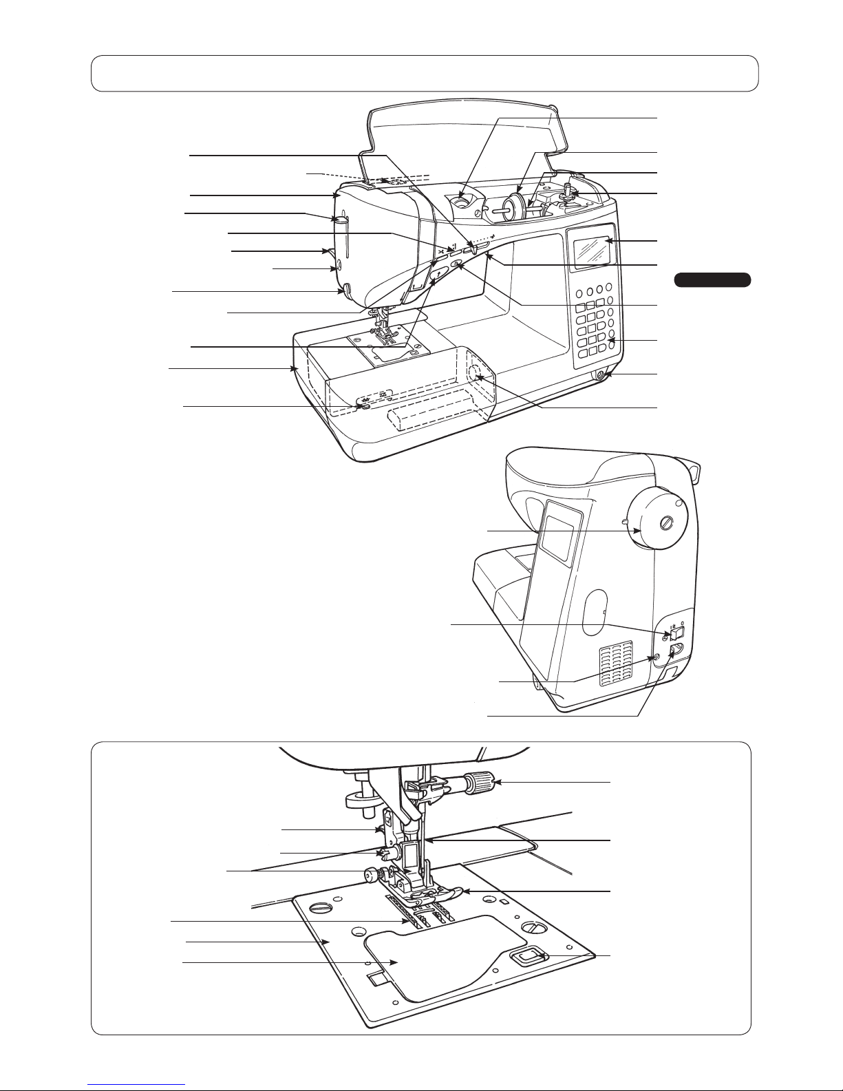
Hand wheel (pulley)
Power switch
Machine receptacle
Controller plug socket
Spool cap (large)
Spool pin
LCD Screen
Operational
buttons
Face plate cover
Threading lever
Start/stop button
Auxiliary bed
(accessory case)
Presser foot lifting lever
Drop feed knob
Needle setscrew
Needle
Presser foot
Sensor pinhole for buttonholing
Presser foot releasing button
Feed dog
Throat plate
Hook cover
Bobbin winding
shaft
Hook cover release
button
Presser foot holder setscrew
Presser foot holder
Thread trimming button
Thread cutter
Reverse stitch
button
Speed controller
Needle up/down button
Presser foot pressure adjustment dial
Thread tension
adjustment dial
Pattern
adjustment dial
Knee lifting lever
hole
Light under arm
F600 Only
[2] Principal parts
– 4 –
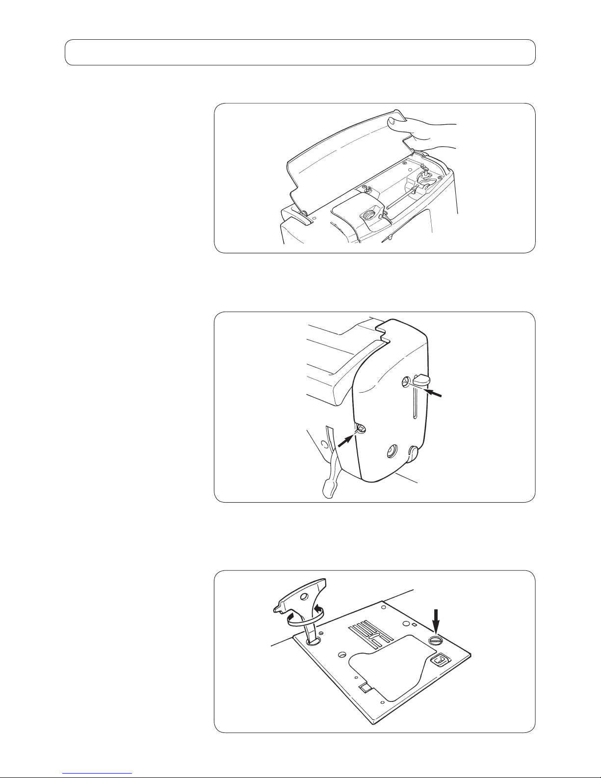
○
To remove the top cover, bow the hinge section of the right side of the cover.
○
Remove setscrews 1 and 2 from the cover. Then, remove the cover.
○
Remove setscrews 3 and 4 from the throat plate.
Then remove the throat plate.
[3] Disassembling the machine covers
1) Top cover
2) Face cover
3) Throat plate
1
2
3
4
– 5 –
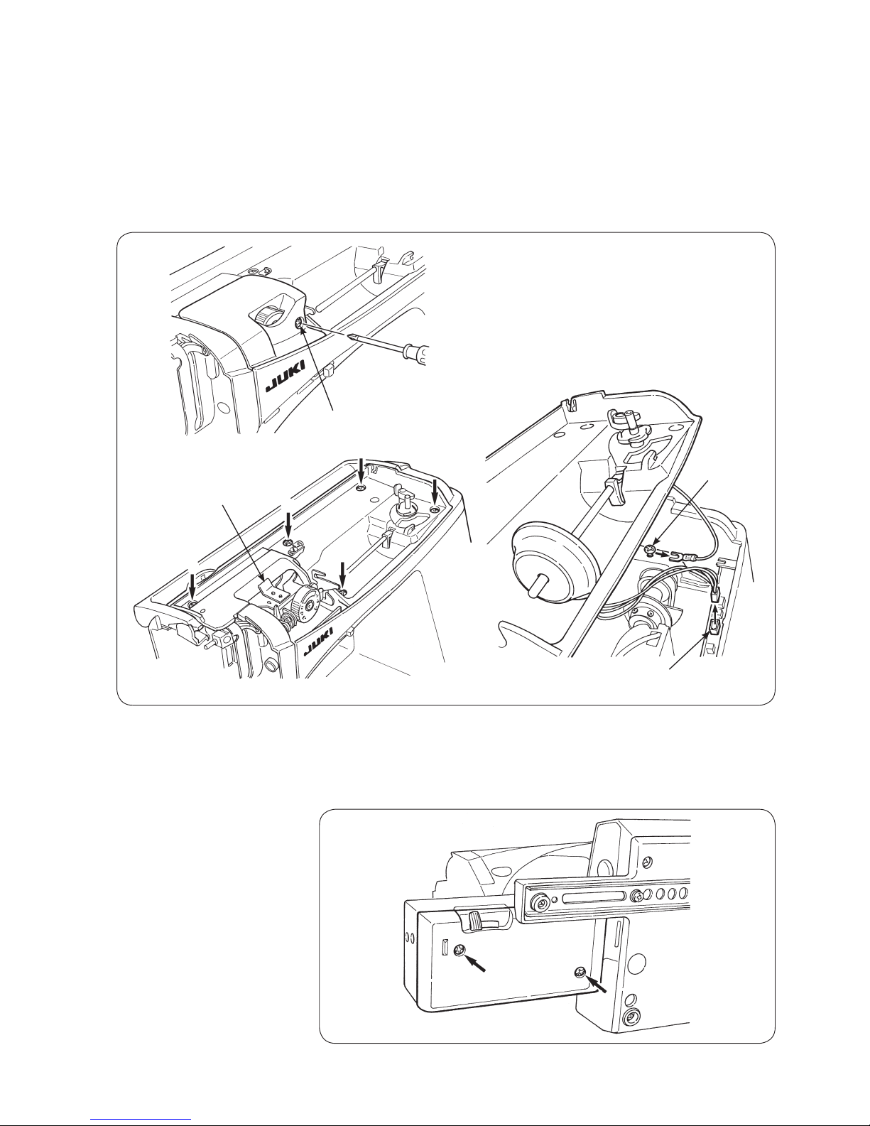
○
Remove setscrew 5 from the thread tension cover.
Remove the thread tension cover.
○
Remove setscrews 6 to !0 from the spool cover.
○
Pull out the cable of bobbin winder motor from the microcomputer PCB.
Loosen the setscrew of the grounding wire. Remove the grounding wire.
○
Remove the spool cover from the main unit of the machine, paying attention
to the base tension.
○
Remove setscrews !1 and !2 from the bottom cover of the free arm.
Remove the bottom cover.
4) Spool cover
5) Bottom cover of the free
arm
!1
!2
6
7
8
9
!0
5
Microcomputer PCB
Setscrew
of the
grounding
wire
Base tension
– 6 –
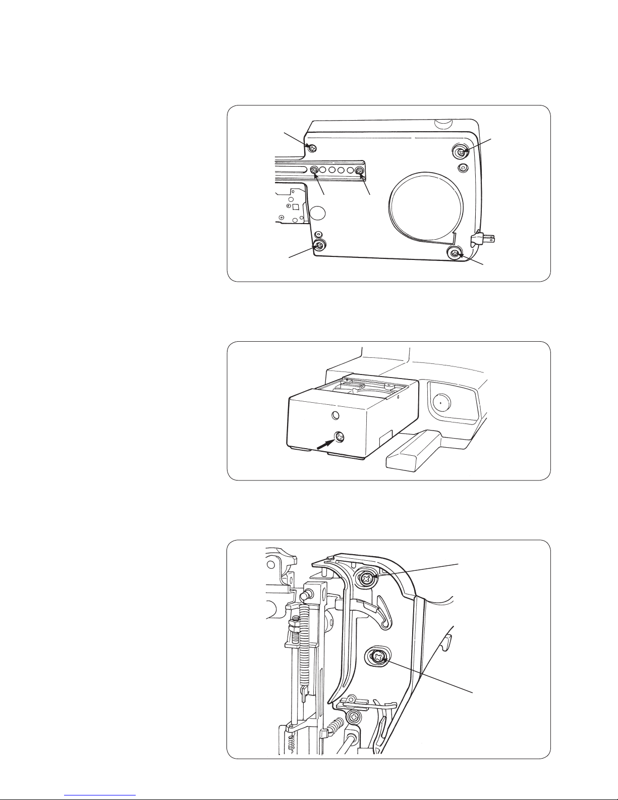
6) Bed cover
7) Upper cover of the free
arm
8) Face plate cover
○
Remove setscrews !3 to !5 from the rubber cushion of the bed cover.
Remove setscrew !6 from the bed cover. Remove setscrews !7 and !8 from
the metal plate. Remove the bed cover.
○
Remove setscrew !9 from the upper cover of the free arm.
Remove the cover.
○
Remove setscrews @0 and @1 from the face plate cover.
Remove the face plate cover.
!9
!3
!4
!5
!6
!7
!8
@0
@1
– 7 –
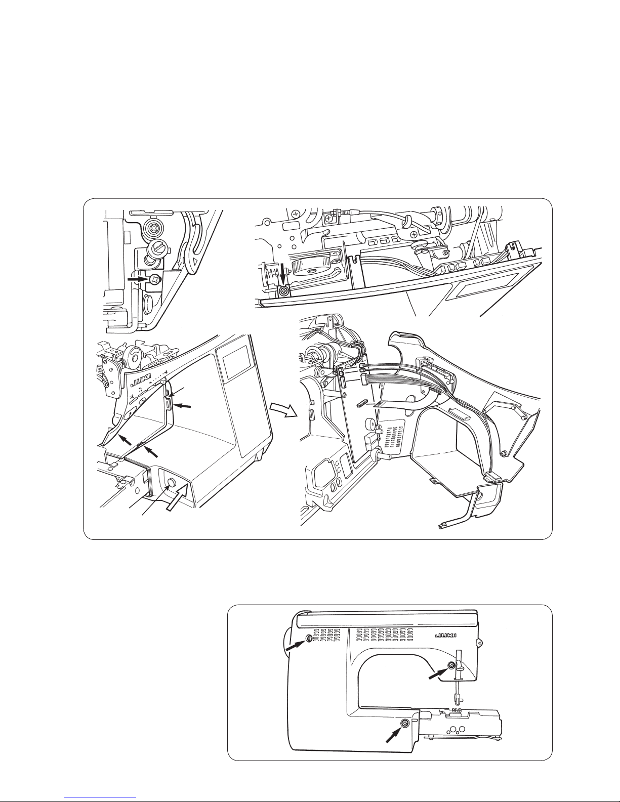
9) Front panel
○
Pull out the pattern adjustment dial.
○
Remove setscrews @2 and @3 from the front panel.
○
Put a thin screwdriver in the notch in the rising section under the arm and pry
off the front panel and hook A of the rear panel.
○
Opening the right side of the front panel in the direction of the arrow, tap Z
section with your hand to remove hook B located at the bed surface.
○
Lastly, remove hook C located at the lower side of the machine jaw.
○
Remove connectors for SUMI-card, start switch and LED lamp from the
microcomputer PCB when necessary.
@3
@2
Notch
A
B
C
Z
Open
@4
@5
@6
10) Rear panel
○
Remove setscrews @4, @5 and @6 from the rear panel.
Remove the rear panel with the presser foot lifting lever raised.
Pattern adjustment dial
 Loading...