

JUKI HZL-350Z series, HZL-353Z, HZL-355Z, HZL-357Z Service Manual
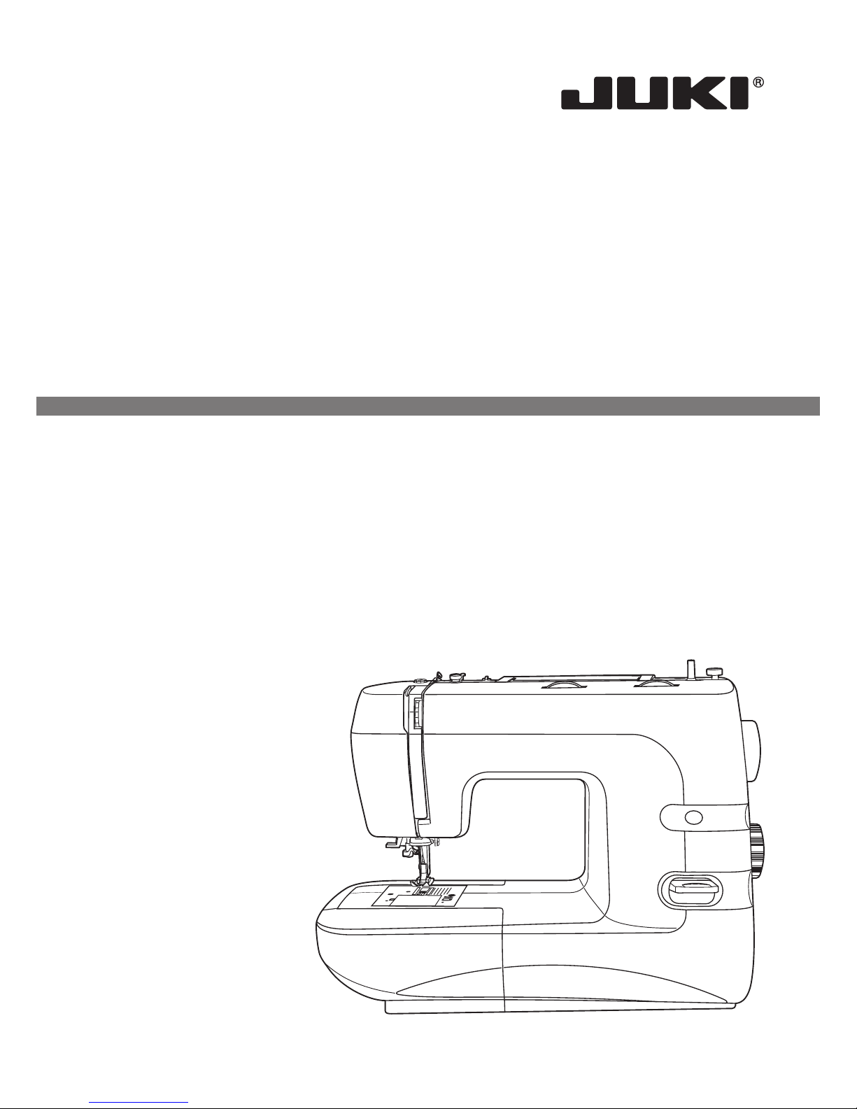
SEWING MACHINE
HZL-350Z series
SERVICE MANUAL

1
ATTENTION
Be sure to observe the following, as they may well become causes for fire, electric-shock,
injuries, and damage to parts.
-Be sure to unplug power source before engaged in disassembly, installation, adjustment.
-In case of installing please pay special care to clamp electrical cords, etc., scars to sheath,
mis-circuit, etc.
-Be sure to use regular standard part in replacing.
CONTENTS
1. Products specification
2. Out look
3. Names of principal parts
4. Removing methods of external parts
5. Adjusting methods of each part
.............................................................................................................2
.....................................................................................................................................3
.........................................................................................................4
4.1
4.2 Face plate .........................................................................................................................5
4.3 Cord reel cover .................................................................................................................5
4.4 Belt cover..........................................................................................................................5
4.5 ...........................................................................................................6
4.6 .................................................................................................................6
4.7 Front cover ....................................................................................................................6-7
4.8 Back cover ........................................................................................................................8
55.1 Symbol instructions...........................................................................................................9
.2 Play of arm shaft.............................................................................................................10
5.3 Drop middle point of needle............................................................................................10
5.4 Height of presser foot......................................................................................................11
5.5 Needle flow at maximum zigzag width............................................................................12
5.6 Drop middle point of needle............................................................................................13
5.7 Needle position of zigzag................................................................................................14
5.8 Automatic needle threader adjustment ...........................................................................15
5.9 Adjustment of feed rock shaft and feed lifting rock cam .................................................16
5.10 Height of needle bar .......................................................................................................17
5.11 Timing of needle and hook..............................................................................................18
5.12 Distance-needle-hook.....................................................................................................19
5.13 Play between shuttle driver shaft gear and lower shaft gear..........................................20
5.14 Play of shuttle driver shaft ..............................................................................................21
5.15 Feed-dog height..............................................................................................................22
5.16 Position of feed-dog in relation to the needle plate (left to right) ....................................23
5.17 Upper thread tension adjustment....................................................................................24
5.18 Shuttle hook tension adjustment.....................................................................................25
5.19 Motor belt tension ...........................................................................................................26
5.20 Drop point of needle .......................................................................................................27
5.21 Forward and reverse stitching in buttonhole sewing
(Feeding pitch of reverse and forward stitching is not even) ..........................................28
5.22 Bar tack density (stitch advances in upper or lower bar tacking)....................................29
5.23 Buttonhole length adjustment .........................................................................................30
5.24 Bobbin winding problem .................................................................................................31
..................................................................................................................32-336. Circuit diagram
Sewing table .....................................................................................................................5
Free arm foot bush
Free arm cover
2
1. Products specification
Machine style
Size of machine (L xWxH)
Weight (kg)
Max rotation speed (rpm)
Motor power
Motor type
Rotation control method
Needle position
Zigzag out-breaking device
Hook system
Thread take up lever
Presser foot lift
Needle threader
Needle plate
Upper thread tension adjust device
Bobbin winder
Reverse
Press-bar pressure regulating device
Kinds of stitches
BH micro adjust device
Dials
Zigzag conversion device
Stitch length adjust device
Button hole system
Pattern indicating device
Max. length of stitch (mm)
Max. width of zigzag (mm)
Face plate upper plate
Sewing table
LED lamp
Speed control device
Power supply switch
Hard case
Nos. of accessories
Lower thread remainder indicator
Free arm
177 x 410 x 308 mm
7.1 (Only machine)
750 50
70W
Series wound / AC
Electric type
Center and left position
Multiple-player cams conversion type
Horizontal hook
Slit type
Two-steps type
Auto type
Screw fixing type
Top of upper plate inclusive turning knob
Self releasing with automatic stop
Press down type
Yes
21 26 32
Yes
3
Dial type
Dial type
1-step
Indicated in a transparent window pattern to be selected
4.5
7
Plastic
Coupled with accessories / spare parts box
Inclusive within face plate
Controller
Pulsating, two steps
Yes
Option
Needle plate, cover type
TYPE
ITEM
353Z
355Z 357Z
3
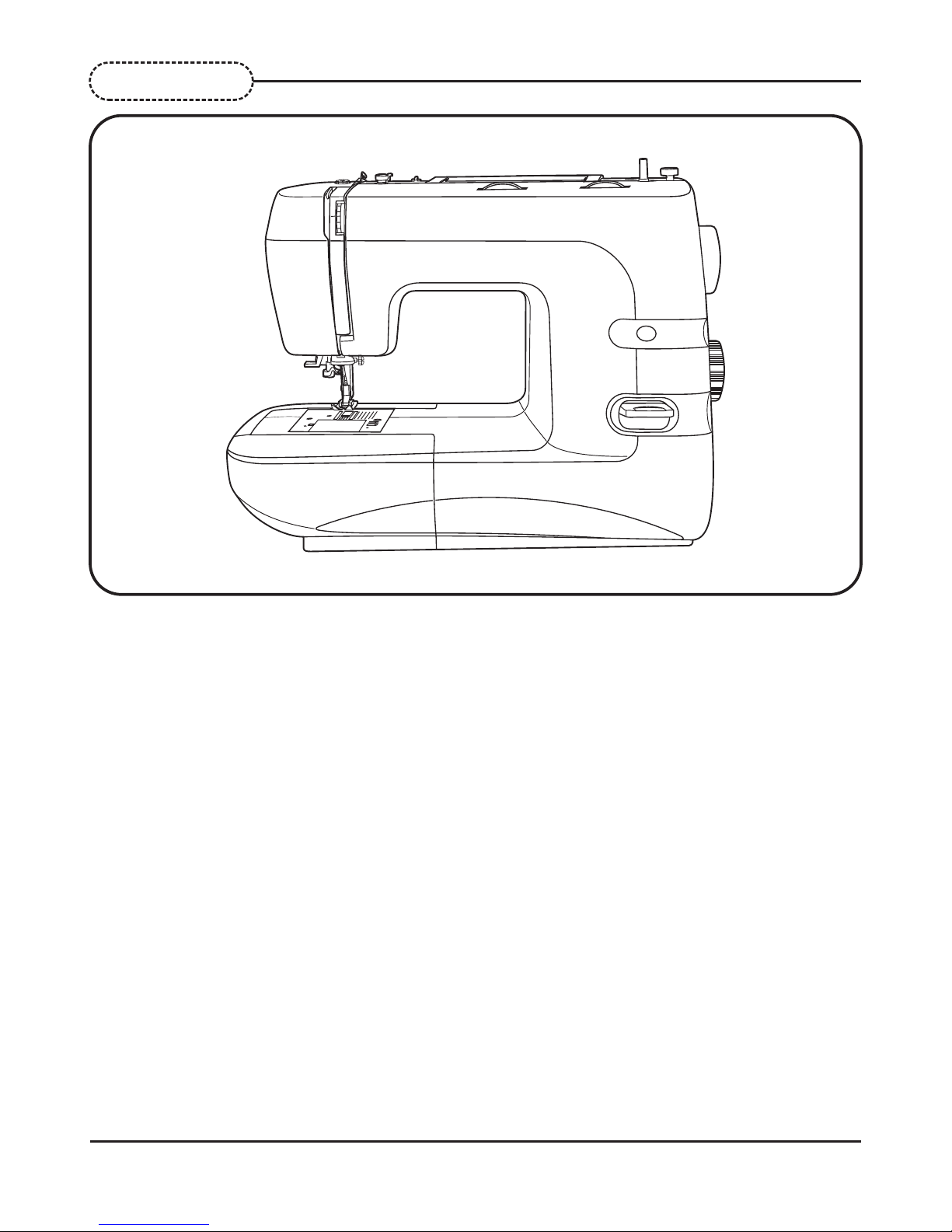
2. Out look
4
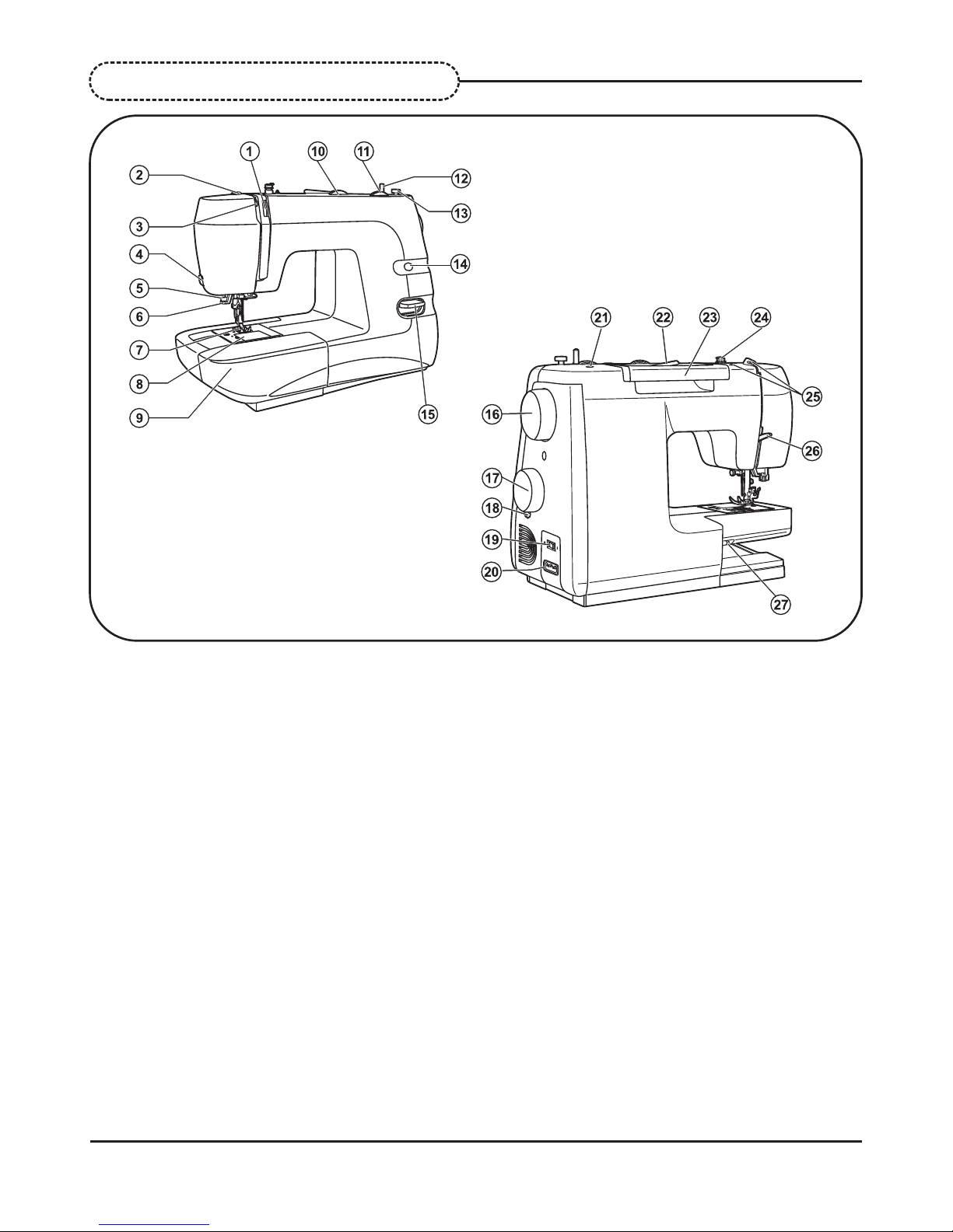
3. Names of principal parts
1. Tension dial
2. Presser foot pressure
3. Thread take up lever
4. Thread cutter
7. Presser foot
8. Needle plate cover
9. Sewing table and accessory box
10.Stitch width dial
11.Stitch length dial
12.Bobbin winder spindle
13.Bobbin winder stopper
14.Stitch display
15.Reverse lever
16.Handwheel
17.Patten selector dial
18.Buttonhole balance control dial
19.Main switch
20.Main plug socket
21.Hole for second spool pin
22.Spool pin
23.Handle
24.Bobbin thread guide
25.Upper thread guides
26.Presser foot lever
27.Drop feed control
5. One step buttonhole lever
6. Automatic threader
2
5
c
d
e
b
3
f
g
Belt cover
4
Cord reel cover
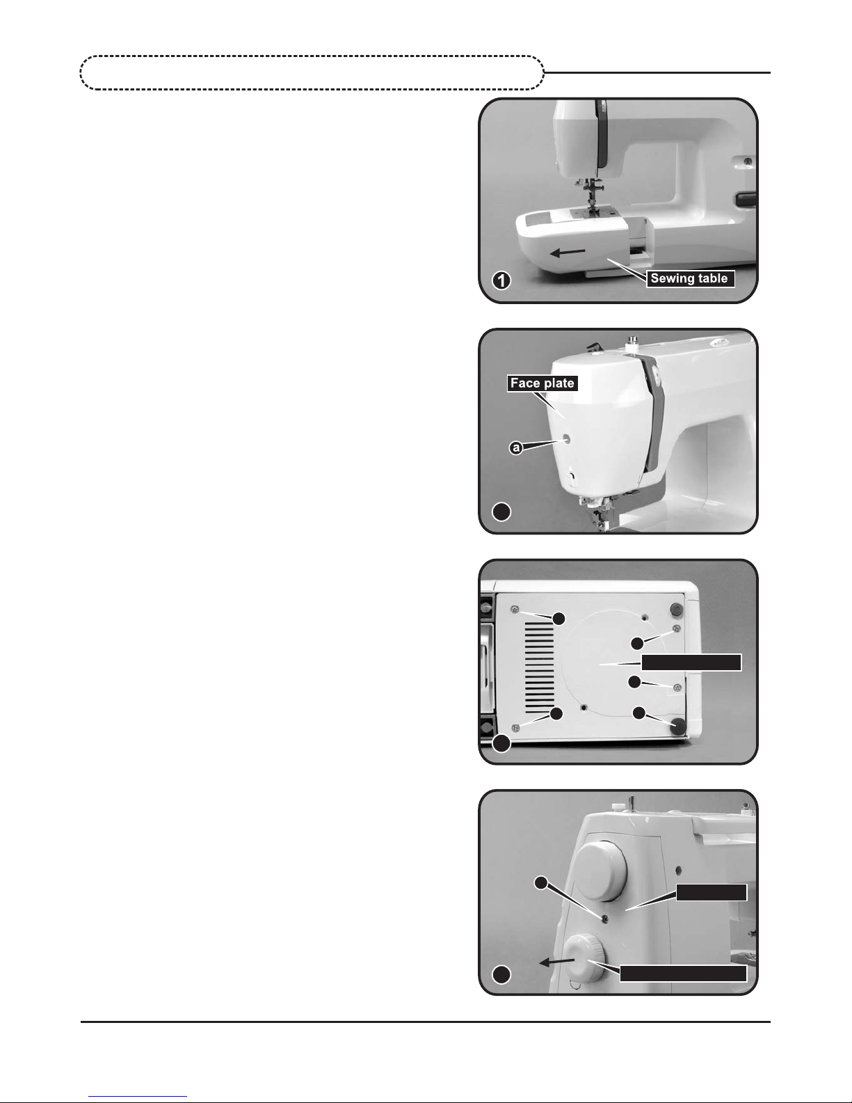
4-1 Sewing table
Remove the sewing table. (1)
4-2 Face plate
Remove screw (a) and remove the face plate.(2)
4-3 Cord reel cover
- Lay down machine. Remove 1 cushion
rubbers (b).
- Remove 4 screws (c, d, e, f). (3)
- Remove cord reel cover.
4-4 Belt cover
- Remove the screw (g).
- Remove the patten selector dial
- Remove belt cover. (4)
4. Removing methods of external parts
Patten selector dial
6
n
Back cover
h
Free arm foot bush
i
j
k
5
7
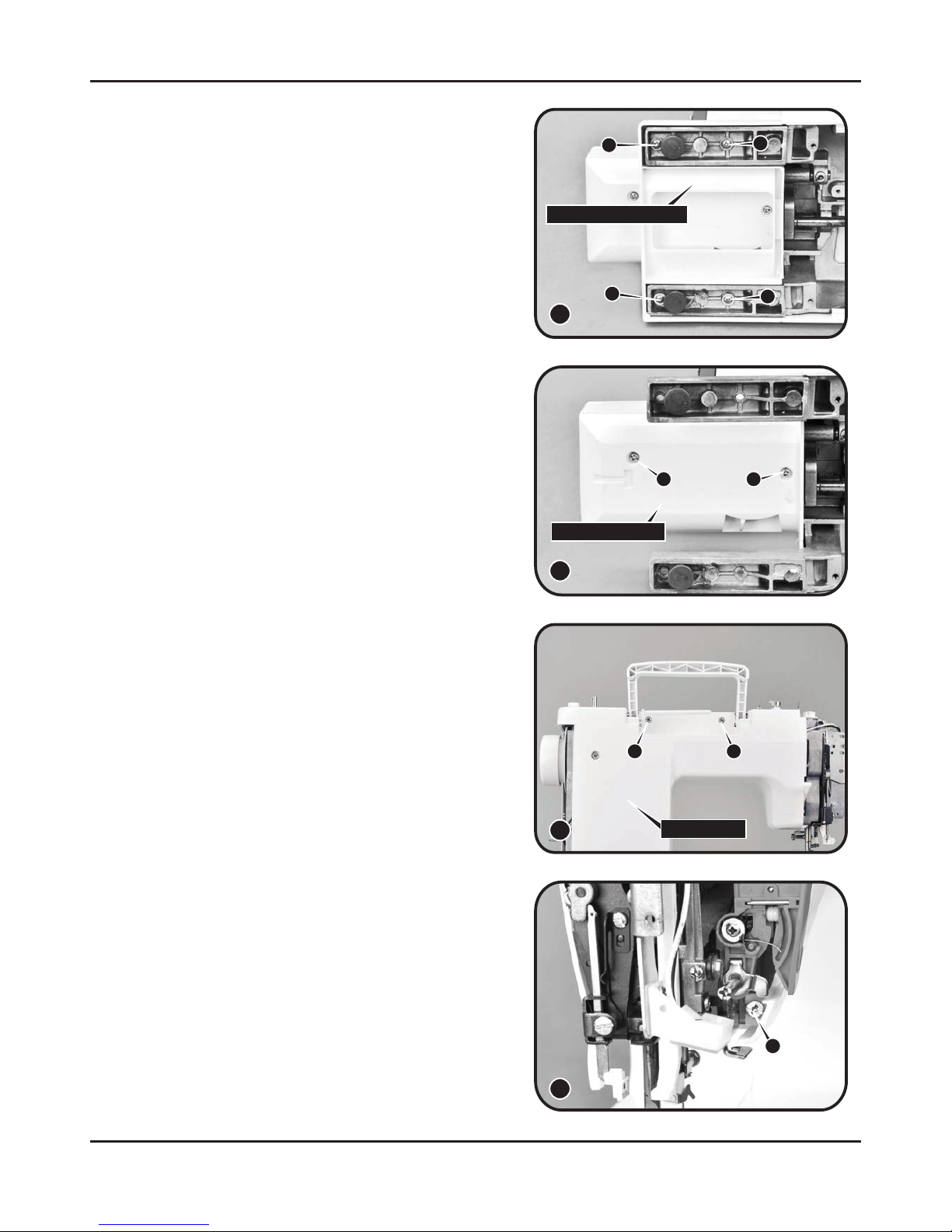
4-5 Free arm foot bush
Remove 4 screws (h, i, j, k) and remove the free
arm foot bush. (5)
4-6 Free arm cover
Remove 2 screws (l, m) and remove the free
arm cover. (6)
4-7 Front cover
- Remove face plate, arm top cover, sewing
box complete, cord reel cover, belt cover, and
free arm cover and free arm foot bush first.
- Lift handle and remove 2 screws (n, o). (7)
- Loosen screw (p) about 3mm. ---(8)
8
p
l
Free arm cover
m
6
o
7
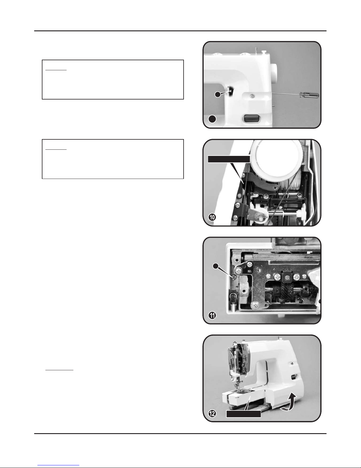
Operation hole
r
q
9
- Remove front cover following direction of
arrow. (12)
Attention:
Be sure to remove the front cover carefully,
because the leader wire and the body are
connected together.
- Remove screw (r). (11)
- Loosen screw (q) about 3mm. (9)
First using electric torch (flash light) etc to
locate screw (q) position which deeply inside
the machine.
Note 1:
Front cover
Note 2:
To reach the screw (q), use Philips type
screwdriver through the operation hole on
plate. (10)
8
Back cover
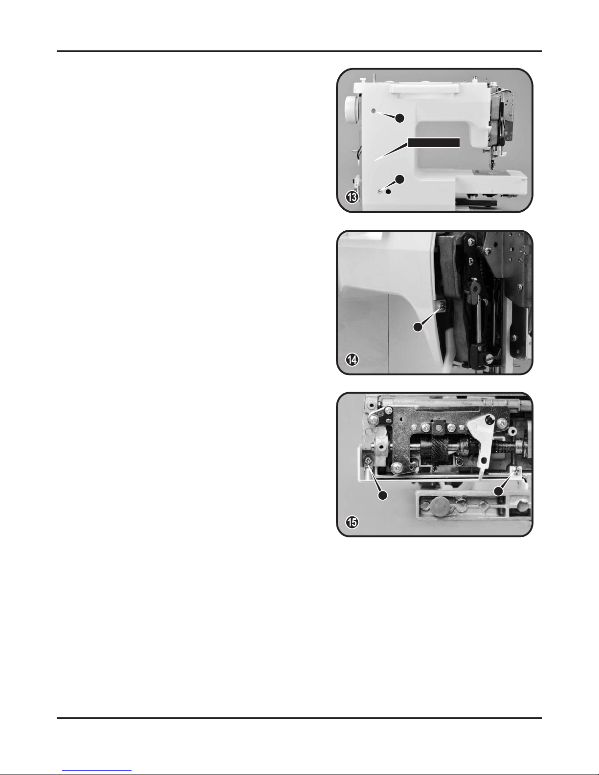
4-8 Back cover
- Remove 2 screws (s, t). (13)
- Loosen screw (u) about 3mm. (14)
- Remove screw (v).
- Loosen screw (w) about 3mm.
- Remove the back cover. (15)
w
u
v
t
s

5-1 Symbol instructions
5. Adjusting methods of each part
Noise occur while the machine is running.
Skip-over stitching, needle breakage, and problems associated with needle.
Delivery of cloth to be in disorder and insufficient, problems associated with delivery
amount.
Stitch tightening problem.
BH right and left stitching is not even, incorrect length and problems associated with
buttonhole sewing.
Bobbin winding problem.
9
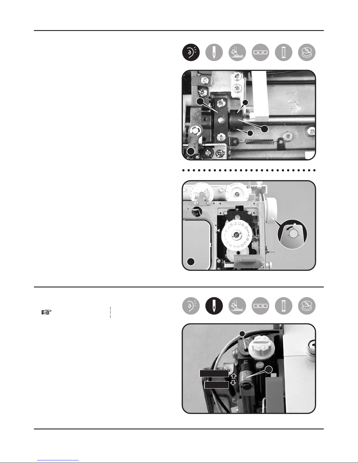
5-3 Drop middle point of needle
- Choose patterns , zigzag 0 mm.
- Remove face plate.
- Loosen screw (a) of needle bar supporter.
- Turn needle bar supporter (A) forward /
backward to adjust needle.
Backward = to move needle forward
Forward = to move needle backward
- Set needle position above center of
needle plate and fasten screw (a).
a
b
A
B
2
1
10
a
A
5-2 Play of arm shaft
- Remove the face plate and arm top
cover.
- Remove the 2 screws (a, b) of arm shaft
collar (A). ---(1)
- Pull hand wheel backward.
- Push arm shaft collar (A) to left tightly
against arm shaft bushing (B), and then
fasten and secure screws (a, b). ---(1)
- Be sure proper distance between arm
shaft collar and arm shaft bushing. ---(2)
- Be sure arm shaft operates smoothly
after adjustment.
- Arm shaft collar and arm shaft bushing
being too tightly closed might cause
insufficient operation of arm shaft.
- Follow step, in order to re-adjust.
backward
forward
 Loading...