

Page 1
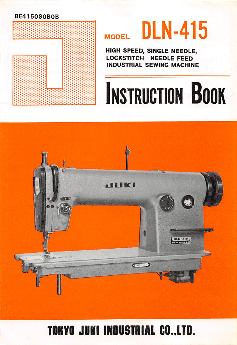
BE4150S0B0B
MODEL
HIGH
SPEED, SINGLE NEEDLE,
LOCKSTITCH
INDUSTRIAL
DLN-415
NEEDLE
SEWING
FEED
MACHINE
Instruction
Book
TOKYO
JOKI
CiiE=>
INDUSTRIAL
OLN'A1S
C0..1TD
Page 2
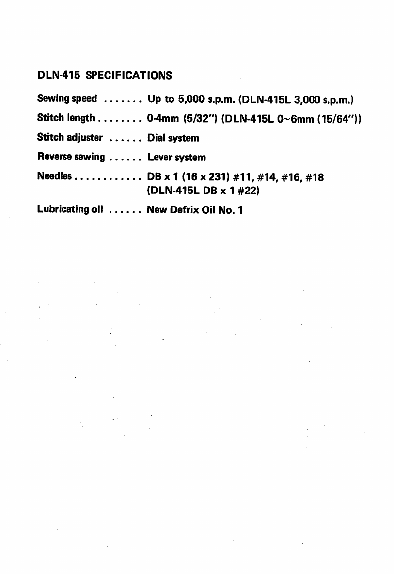
DLN-415
SPECIFICATIONS
Sewing
Stitch length
Stitch adjuster Dial system
Reverse sewing Lever system
Needles DBx
Lubricating oil New Defrix Oil No. 1
speed Upto 5,000 s.p.m.
04mm
(DLN
{5/32")
1(16
415L
(DLN415L
x 231)
DB x 1
#11,
(DLN-415L
0~6mm
#14,
#16,
#22)
3,000 s.p.m.)
(15/64"))
#18
Page 3
DLN-415
Installing
Motor
Cautionsonoperating
Lubrication
1.
2.
3.
Threading
Preparationofthe
1. Inserting &
2.
3.
The
Adjusting
Thread
Adjusting
Presser
Adjusting
The
Heightofthe
The
Adjusting
Reverse
Pushing
Inserting
Installing
Relation
Adjusting
Adjusting
DLN-415-L
the
oil
reservoir
pulley
and
the
belt
the
machine
Adjusting
The
Adjusting
Winding
Howtoinsert
thread
presser
stitch
the
oil
supplytothe
face
oil adjusting pin 4
the
oil
the
tension
the
take-up
the
foot
the
the
and
foot
supplytothe
machine
bobbin
removing
bobbin
needle
the
the
thread
bobbin
thread
spring
bobbin
thread
feed
dog
pressureofthe
hand
lifter
feed
dog
hook
thread
bobbin
case
tension
.tension
presser
.'. ; 8
length
the
stitch
length
sewing
pressureofthe
the
needle
and
removing
between
the
heightofthe
the
amountofthe
INSTRUCTION
the
feed
hook
the
lever
sewing
and
presser
thread
BOOK
the
hook
needle
bar
take-up
(Note) Duetoimprovementsonthe
this
INSTRUCTION
BOOK
mightbechanged
part
components
foot
machine,
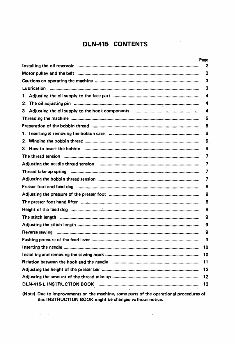
CONTENTS
some
parts of
without
the
operational
notice.
•.
procedures
Page
2
2
3
3
4
4
5
6
6
6
6
7
7
7
7
8
8
8
9
9
9
9
10
10
11
12
12
13
of
Page 4
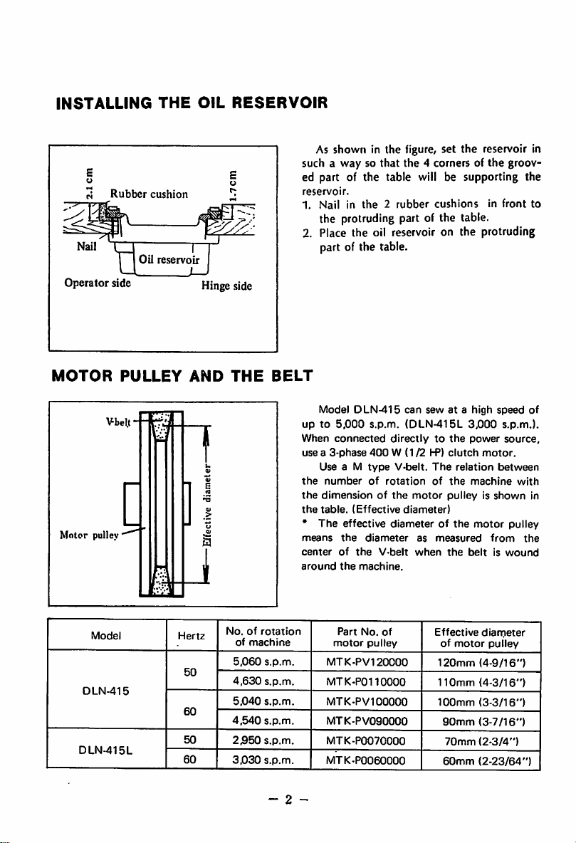
INSTALLING
Rubber
I 1
Operator
side
Oil
THE
cushion
reservoir
OIL
1_
Hinge side
RESERVOIR
such a way so that the 4 corners of
ed part of the table will be supporting the
reservoir.
1. Nail in
2. Place the oil reservoir on the protruding
As shown in the figure, set the reservoir in
the
groov
the2rubber
cushionsinfront
the protruding part of the table.
part of the table.
to
MOTOR
Motor
DLN-415
DLN-415L
pullev
Model
PULLEY
Hertz
50
60
50
60
AND
THE
BELT
No.ofrotation
of
machine
5,060
s.p.m.
4,630
s.p.m.
5,040
s.p.m.
4,540
s.p.m.
2,950
s.p.m.
3,030
s.p.m.
Model
DLN-415
upto5,000
When
connected
usea3-phase
Use a M
the
number
the
dimensionofthe
the
table.
•
mrans
centerofthe
around
(Effective
The
effective
the
the
Part
motor
MTK-PV120000
MTK-P0110000
MTK-PV100000
MTK-PV090000
MTK-P0070000
MTK-P0060000
s.p.m.
directlytothe
400
W (1/2HP)
type
V-belt.
of
rotation
diameterofthe
diameter
V-belt
machine.
No.
of
pulley
can
sewata
(DLN-415L
The
of
motor
diameter)
as
measured
when
Effective
of
120mm
110mm
100mm
90mm
70mm
60mm
high
speed
3,000
s.p.m.).
power
source,
clutch
motor.
relation
the
between
machine
pulleyisshown
motor
pulley
the
from
beltiswound
dian^ieter
motor
pulley
(4-9/16")
(4-3/16")
(3-3/16")
(3-7/16")
(2-3/4")
(2-23/64")
of
with
in
the
- 2 -
Page 5
CAUTIONS
ON
OPERATING
THE
MACHINE
® Do not run the
with
fresh
oil.
machine,
under any
circumstances,
before the oil
reservoirisfilled
up
® Always rotate the machine toward the operator. Do not run the machine in the re
verse
direction.
® This machine can run with a speed of up to 5,000 s.p.m. but for the first month drop
the speed to
about
4,500 s.p.m. (DLN-415L 2,500 s.p.m.)
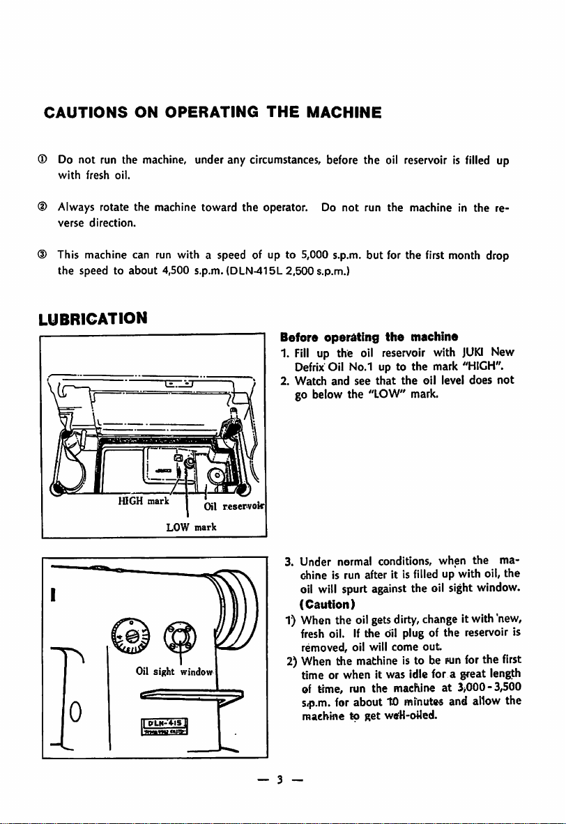
LUBRICATION
Before
1.
2.
HIGH
mark
Oil sight window
0
OLM-4-15]
LOW
mark
Oil
reservoir
operating
Fill
up the oil reservoir with
Defrix
Oil No.1 up to the mark
Watch
and
go below the
3.
Under
normal
chine is run after it Is filled up with oil, the
oil
will
spurt
(Caution)
1) When the oilgets
see
"LOW"
against
the
machine
that
the
mark.
conditions,
the oil sight
dirty,
oil level
when
change
JUKI
"HIGH".
does
the
window.
itwith
fresh oil. Ifthe oil plug of the reservoir is
removed,
2)
When
the
oil will
machine
come
isto be
out
pun
for
time or when it was idle for a great length
of time, run the
S4).m.
for
machine to get wtfH-oUed.
macFiirieat3>000-3,500
abouttO
minutes
and
allow
New
not
"new,
the
ma
first
the
— 3 —
Page 6

Oil
adjusting pin
Oil
amount
gets
less
Oil amount
' I I
Needle
bar
Oil
adjusting
Arm
Oil adjusting pin
Counterweight
Crank
gets
more
fl
crank
Grooveofeccentric
shaft
screw
1.
Adjusting
part
the
oil
supplytothe
face
When adjusting the oil supply to the thread
take-up and needle bai crank components,
remove the face plate and the oil prevent
ing plate and adjust by turning the oil ad
justing pin at the tip of the main
1. When
the
red mark of the adjusting pin
comes near the crank, the oil
less.
2. When
the
red mark comes to the opposite
shaft
amount
gets
side of the crank, the oil amount gets more.
(Caution)
The oil amount
does
not
change
immedi
ately after the adjustment, so when ad
justing,
2.
1. The oil adjusting pin has a carved groove
2. When the groove is at the opposite side of
3. The red mark on the oil adjuster shows the
have
this in mind.
The
oil
adjusting
pin
as shown in the figure. When this groove
and
the
oil
holeofthe
main
shaft
come
together, the oil amount gets more.
the oil hole,
the
oil
amount
gets less.
side without the carved groove.
Oil regulating valve
3. Adjusting
components
the
oil
supplytothe
The supply of oil to the hook components
can be adjusted by the oil regulating valve on
the
hook
shaft.
1.Ifthis valve is turned toward © side(right),
the oil amount gets more,
2. Ifthis valve is turned to © side (left), the
amount
- 4 -
gets less.
hook
Page 7

THREADING
Rotate
the
hand
1. Pass the needle thread in the order shown by the
2.
Pass
the
3.
Pull
jDut
THE
MACHINE
wheeltoright
thread
to the
and
needle
about10cm(4")of the
eye
place
from
thread
the
leftto
from
thread
the
take-up
figure.
right.
needle
eye.
to the
highest
position.
- 5 -
Page 8

PREPARATION
OF
THE
BOBBIN THREAD
Bobbin
Pulleys
Trip
case
latch
Adjusting
screw
Tension
base
disc
Inserting&removing
the
bobbin
case
1. Rotate the hand wheel with your hand and
bring the needle to its highest position.
2. Tilt the machine and support it by the head
support on the table.
3. Lift up
the
takeitout.
knob of
the
bobbin
case
and
* If you hold the knob in open condition,
bobbin
will
not
fall
off.
4. To insert the bobbin case, insert it deep
into
the
shaftofthe
hooksothat
the
nose
of the bobbin case fully enters the groove
of
the
hook
and
then
close
the
knob.
Winding
1.
2.
the
bobbin
Set
the
screws.
Pass
bobbin
the
threadinthe
figure and wind it
al
times.
winder
around
thread
to
order
the
showninthe
the
bobbin sever
table
with
3. Knock down the trip latch and contact the
pulley to the belt.
4. Adjust the winding amount by the winding
adjusting screw so
that
about
80% is wound.
5. When the thread is wound unevenly, move
the
thread
tension
disc
base
to
left
and
correct to even winding condition.
6. When the winding is completed, the trip
latch will be released and the pulley will
stop automatically.
Thread
hole
Thread
passing
hole
- 6 -
Howtoinsert
1.
Hold
the
casesothat
condition.
2. Pass
3.
of
Then
the
out
*When
the
the
the
bobbin
pull
thread
through
pulling
bobbininthe
the
bobbin
bobbin
and
the
thread
threadtothe
case.
the
thread
tension
spring
the
thread
the
bobbin
arrow
insertitto
willbein
thread
and
it will
and
hole.
thread,
direction.
the
bobbin
right-twist
passing
hole
pass
under
canbepulled
rotate
Page 9

THE
THREAD
TENSION
Moving
®ow»
range
Thread
M I
Weaker
n
'-'Thread tension nut
Thread
take-up
tension
bar
Set
_
spring
screw
Stronger
Adjusting
Ideal
the
stitches
needle
are
formed
thread
when
tension
the
needle
thread and the bobbin thread are perfectly
interlockedatthe
centerofthe
cloth.
The tension of the needle thread is adjusted
by the thread tension nut.
1. Turn it to right to make the tension stronger
andtothe
Thread
*Tochange
tension
1. Loosen
bracket
2.
Rotate
*Tochange
up spring
lefttomakeitweaker.
take-up
the
the
spring:
the
thread
the
spring
moving
screwofthe
tension
strength
range
bar.
of the
ofthe
thread
tliread
thread
tension
take-
1. Loosen the set screw, remove the thread
tension
2. Loosen
3. When
turned
bar
the
and adjust.
the
right,
the
to left, it will
thread
tension
bar
set
screw
thread tension bar is turned to
spring
will
get
get
stronger
weaker.
Thread
bar
and if
tension
set
screw
Adjust
inff
0
Li
Adjusting
Rotate
Thread take-up spring
the
bobbin
the
thread
thread
tension
tension
screw of
the
bobbin case to adjust the bobbin thread
tension.
1. Rotateit to rightto makethe bobbin thread
tension stronger and to left to make it
sc
- 7 -
weaker.
Page 10

PRESSER
FOOT
AND
FEED
DOG
Pressure
Hand
lifter
adjusting
screw
_///
\I
W
ffi
Adjusting
foot
the
pressureofthe
presser
1. Turn the pressure adjusting screw to right
to make the pressure stronger and to left
to
makeitweaker.
Normal pressure for general fabric is about
5 kg (11 lbs).
Ifa pressure of more than 6 kg
required, use the
accessory box.
Presser
lifter
Turn
the
rear of
the
machine
and
the
presser
(13/64")
will
lifter,
10 mm
Push
come
the
125/64")
from
down
downtopress
presser
hand
foot
the
hand
from
exchanging
lifting lever
head
either
will goupfor
throat
plate
lifter,
the
foot
will go up for
the
throat
and
(13.2
spring in the
locatedinthe
to left or right,
about5mm
surface.
the
presser
work.Bythe
plate
surface.
lbs) is
foot
knee
about
Feed
driving fork
Clamp
TA
screw
Heightofthe
feed
dog
The height of the feed dog from the surface
of the throat plate is set from 0.7-0.8mm. In
sewing light weight materials, if this height is
too high,shrink-stitching may
To adjust the height of the
1. Loosen the clamping screw of the feed driv
ing fork of the compound feed.
result.
feed
dog:
2. Move the feed dog base up and down and
adjust.
3.
After
8 -
adjusting,
screw.
f\NN\N\NNv5
I
Feed
doR
tightly
0.7--0.8Em
tighten
the
Throat plate
clamping
Page 11

THE
STITCH
LENGTH
Feed
adjusting
DLN-4-15
dial
Lever
Adjusting
The
stitch
the
length
stitch
length
can be adjusted by
turning
the feed adjusting dial above the feed lever.
The figures on the graduator are shown in
mm.
1. Rotate the feed adjusting dial either to right
or
left.
2. And match the desired
which is coming
* The
maximum
Reverse
stitch length is 4mm(5/32")
sewing
figure
out
from the arm.
with the pin
1. For reverse sewing, push the feed lever
down.
2. As long as this lever is kept down, reverse
sewing can be performed.
3.
Release
this
lever
and
the
feed
lever
will
return to original position and normal
A
straight stitching can be resumed.
AdjustinK nut
Pushing
pressure
of
the
food
Irrespective of the length of stitches, the
pull-up spring is somewhat strengthened so
that during high speed sewing if the hand is
released from the feed lever, it will positively
return to the original position.
When
shorter
the
rotationofthe
stitches
are
machineistobeslowed
desiredorwhen
down, it is possible to decrease the pushing
pressure of
the
feed lever.
1. When the adjusting nut is loosened, the
pressure will
become
weaker
is tightened, the pressure will become
stronger.
- 9 -
and
lever
if the
nut
Page 12

INSERTING
THE
NEEDLE
Set
screw
Needle
INSTALLING
Feed
base
screw
AND
Bobbin
Groove
REMOVING
case
positioning
screw
Use DB X 1 needles. There
numbers
and
sizes of
the
needle,
are
so
many
select
the correct size and number depending on the
thickness of
material.
1. Rotate the hand wheel and bring
the
thread or kinds of sewing
the
needle
bar to the highest position.
2. Loosen
3. Hold the needle so
the
needle clamp screw.
that
the long groove of
the needle comes to your left side.
the
4. Insert the needle deep into
needle
5. Then securely tighten the needle clamping
screw.
THE
SEWING
HOOK
During the runningof the machine, if thread
hards get into the hook or the position of the
hook changes for some reason or to exchange
the
hook
bar to
Remove
withanew
the
hand wheel and bring
the
highest position.
the
the
order:
1. Rotate
2.
3. Remove
finger set screw and take
bobbin
one,doas
case
and
the
follows
the
needle
needle
bobbin case base positioning
out
the bobbin
case positioning finger.
4. Loosen the 3 screws of the sewing hook.
hole.
in
5. Rotate
the
hand
wheel
and
feed base to its highest position.
6. Rotate the sewing hook with your hand
and place it in the position as shown in
the figure.
7. Pull the hook to your left and take it out.
-
10
* To install
cedure.
the
hook back, reverse this pro
raise up
the
Page 13

RELATION
BETWEEN
Clamp
screw
THE
HOOK
AND
Match
follows:
THE
the
needle with
NEEDLE
the
1. Rotate the hand wheel and bring
bar to Its lowest position.
2. Loosen
the
needle bar clamping
(Note)
When matching the timing of the needle and
the sewing hook, be sure to set
adjusting dial to "0".
sewing hook as
the
needle
set
screw.
the
feed
(D
DETERMINE
OF
THE
THE
NEEDLE
HEIGHT
BAR
Needle
lower bushing
Upper
indicating
"Lower
\Needle
(2) DETERMINE THE POSITION
OF
THE
Blade
the
hook
Needle
point
sewing
SEWING
of
HOOK
VA
Lower
indicating
(At
this position,
the blade
^ sewinghook with
pointofthe
the
Sewing
bar
line
indicating
bar
line
match
center
the
needle)
hook
line
(Determine
the
heightofthe
3. Match the upper carved line of the needle
bar with the lower edge of the needle bar
lower bushing.
4. Tighten the needle bar clamping set screw.
(Determine
hook)
the
positionofthe
5. Loosen the 3 clamping screws of the hook
so
that
the hook can be rotated freely with
the
hand.
6. Place the hook with your hand to the thread
of
passing position
7.
Rotate
the
hand
wheel
and
carved
lineofthe
needle
bar
edge of the needle bar lower bushing.
8. In this condition, match
the
hook
with
9.
Make
and
the
the
the
clearance
hook blade point to 0.05 mm and
center
the
line of
between
10. Securely tighten the hook clamping set
match
with
blade
needie
sewing
the
the
point
the.needle
the
bar)
lower
lower
of
needle
- 11 -
Page 14

ADJUSTING
THE
HEIGHT
OF
THE
PRESSER
BAR
ADJUSTING
Thread
iC
Presser
THE
bar
guide
clamp
screw
AMOUNT
When the height or
presser bar is to be changed due to the
exchange of presser foot:
1. Remove the rubber plug of the face plate
2.
From
this hole, adjust by loosening the
presser bar clamping screw.
3. After the adjustment, securely tighten the
set
screw.
OF
THREAD TAKE-UP
The amount of the thread take-up should
be changed according to the length of stitches
or thickness of the sewing cloth to produce
ideal
thread
1. When sewing heavy weight materials, move
the thread guide to your left
The thread take-up amount of the take-up
gets
2. When sewing light weight materials, move
the thread guide to your right.
The thread take-up amount gets less.
tension.
more.
the
direction of the
-12-
Page 15

SPECIFICATIONS
Sewing
speed
Stitchlength 0 ~
Needle
USAGE
For
top
stitchingofheavy weight
(Example)
Seats
of cars,
INSTRUCTION
DLN-415-L
Upto3,000
DB X 1
materials
brief
cases, slippers etc.
6mni(
BOOK
15/64")
#22
s.p.m.
(upto12
sheetsofCanton
material)
TIMING
IT
eo
OF
THE
NEEDLE
Blade
the
sewing
Needle
Yl
Jf
Needle
•—O.lmni
k
\ Blade point of
<j
the
sewing
point
hook
of
hook
WITH
THE
SEWING
When
the needle has risen 1.8mm(5/64"), from
its
lowest
upper
endofthe
dead
HOOK
point,
needle
the
distance
eye
and
the
of the sewinghook should be 2.8mm(7/64").
At
that
point,
the
clearance
and the blade point of the sewing hook should
be0.lmm(l/256").
(when
the
between
feed
amount
between
blade
the
is"0".)
the
point
needle
With
the
exception of above, all
other
specifications are identical with DLN-415.
-
13
-
Page 16

TOKYO
JOKI
 Loading...