


THE
AIRCRAFT SYSTEM - AIRPLANE MODE
ULTIMATE
HELICOPTER SYSTEM - HELICOPTER MODE
RADIO CONTROL
AIRCRAFT SYSTEM - GLIDER MODE
SYSTEM
8 C H A N N E L S 1 0 M O D E L M E M O R Y 3 M O D E L T Y P E S • Z P C M / P P M S E L E C T A B L E

XP8103 2
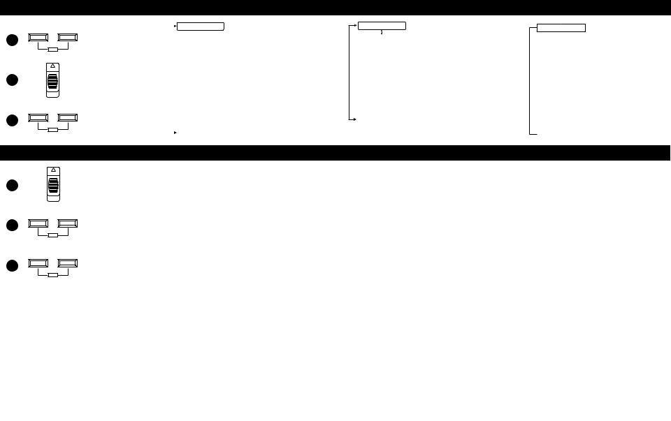
 1-2-3 Programming
|
|
|
Airplane Mode |
|
|
System Set-Up Mode |
|
|
|
|
|
UP – MODE – DN |
Push these two buttons |
|
[INFO-DISP] |
Pg. 28 |
Information Display |
|
|
↕ |
|
||
1 |
and |
|
|
Pg. 29 |
Model Select and Copy |
ENT |
|
|
|
Pg. 29 Model Name Input |
|
|
|
|
|
||
ON |
Turn the power switch |
|
|
Pg. 30 Model Type Selection Function |
|
|
|
|
|
||
2 |
|
|
Pg. 30 |
Data Reset |
|
ON (up). |
|
|
|||
|
|
|
|
||
|
|
|
|
Pg. 31 |
Modulation Selection |
UP – MODE – DN |
Scroll through options |
|
|
Pg. 32 Data Transfer between traqnsmitters |
|
|
|
|
|
||
|
one of these |
|
|
Pg. 34 Wing Type Selection |
|
ENT |
|
|
|
Pg. 35 Spoiler Channel Input Selection |
|
Function Mode
ON
1
UP – MODE – DN
2
ENT
UP – MODE – DN
ENT
power switch
Push these two buttons simultaneously.
Scroll through the functions using one of these buttons.
Pg. 36 |
Dual Rate Exponential |
Pg. 38 |
Reverse Switch |
Pg. 38 |
Sub-Trim |
Pg. 39 |
Travel Adjust (end point adjustment) |
Pg. 39 |
Elevator to Flap Mixing |
Pg. 40 |
Aileron to Rudder Mixing |
Pg. 41 |
Landing System |
Pg. 42 |
Snap Roll |
Pg. 44 |
Differential Aileron Mixing (only if flaperon or |
|
elevons mixing is active) |
Pg. 45 |
Trim Offset Memory |
Pg. 46 |
Flap Knob Operating Value Adjustment |
Pg. 47 |
Programmable Mixing 1 |
Pg. 47 |
Programmable Mixing 2 |
Pg. 47 |
Programmable Mixing 3 |
Pg. 47 |
Programmable Mixing 4 |
Pg. 47 |
Programmable Mixing 5 |
Pg. 47 |
Programmable Mixing 6 |
Pg. 50 |
Fail-Safe/Hold (PCM Only) |
Pg. 52 |
Trainer |
Pg. 54 |
Timer |
Pg. 55 |
Servo Output Values |
Helicopter Mode
[INFO-DISP] |
Pg. 66 |
Information Display |
|
Pg. 66 |
Model Selection and Copy Function |
|
Pg. 67 |
Model Name Input |
|
Pg. 68 |
Model Type Selection |
|
Pg. 68 |
Data Reset |
|
Pg. 69 |
Modulation Selection |
|
Pg. 70 |
Data Transfer |
|
Pg. 72 |
Aux 2, channels can be used for gyro |
|
|
sensitivity adjustment |
Pg. 73 Dual Rate Exponential
Pg. 75 Reverse Switch
Pg. 75 Sub-Trim Adjustment
Pg. 76 Servo Travel Adjust (End Point Adjustment)
Pg. 76 |
Stunt Trim |
Pg. 77 Throttle Hold
Pg. 78 Throttle Curve
Pg. 81 |
Pitch Curve |
Pg. 83 Inverted Flight
Pg. 84 Revolution/Acceleration Mixing
Pg. 85 Gyro Sensitivity Adjustment
Pg. 87 Programmable Mixing 1
Pg. 87 Programmable Mixing 2
Pg. 87 Programmable Mixing 3
Pg. 91 Fail-Safe/Hold (PCM Only)
Pg. 94 |
Trainer |
Pg. 95 Timer Setting
Pg. 97 Servo Output Indicator
Glider Mode
[INFO-DISP]
↕
Pg. 106 |
Model Select And Copy Function |
Pg. 107 |
Model Name Input |
Pg. 108 |
Model Type Selection Function |
Pg. 108 |
Data Reset |
Pg. 109 |
Modulation Selection |
Pg. 110 |
Model Data Transfer |
Pg. 112 |
Wing Type Selection |
Pg.112 |
Flap Channel Input Selection |
Pg. 113 |
Dual Rate/Exponential |
Pg. 114 |
Reverse Switch |
Pg. 114 |
Sub-Trim |
Pg. 115 |
Travel Adjustment |
Pg. 115 |
Elevator To Flap Mixing |
Pg. 116 |
Aileron To Flap Mixing |
|
(Only available when Dual Flap |
|
setting is active) |
Pg. 117 |
Differential |
Pg. 118 |
Flap To Elevator Mixing |
Pg. 119 |
Flap To Aileron Mixing |
Pg. 120 |
Aileron To Rudder Mixing |
Pg. 121 |
Butterfly Mixing (Crow) |
Pg. 122 |
Dual Flap Trim |
Pg. 123 |
Trim Offset |
Pg. 125 |
Programmable Mixing |
Pg. 125 |
Programmable Mixing |
Pg. 125 |
Programmable Mixing |
Pg. 125 |
Programmable Mixing |
Pg. 125 |
Programmable Mixing |
Pg. 125 |
Programmable Mixing |
Pg. 127 |
Fail-Safe (PCM Only) |
Pg. 130 |
Trainer |
Pg. 131 |
Timer Setting |
Pg. 133 |
Servo Output Monitoring |

Table of Contents
1-2-3 Programming Charts . . . . . . . . . . . . . . . . . . . . . . . . . 3
Table of Contents . . . . . . . . . . . . . . . . . . . . . . . . . . . . . . . |
4 |
I.I. IntroductionI uction
How to Use This Manual . . . . . . . . . . . . . . . . . . . . . . . . . . . 8
2. |
Features |
|
|
|
2.1 |
Transmitter NET-G128FS/HS Computer. . . . . . . . |
. 8 |
|
2.2 |
Receiver . . . . . . . . . . . . . . . . . . . . . . . . . . . . |
. 9 |
|
2.3 |
Servo Features . . . . . . . . . . . . . . . . . . . . . . . . . |
9 |
3. |
Component Specifications |
|
|
|
3.1 |
System Specifications (Air/Heli). . . . . . . . . . . . . |
10 |
|
3.2 |
Transmitter Specifications (Air/Heli) . . . . . . . . . . |
10 |
|
3.3 |
Servo Specifications . . . . . . . . . . . . . . . . . . . . |
11 |
|
3.4 |
Receiver Specifications. . . . . . . . . . . . . . . . . . . |
11 |
|
3.5 |
Charger Specifications. . . . . . . . . . . . . . . . . . . |
11 |
|
3.6 |
Airborne Battery Pack . . . . . . . . . . . . . . . . . . . |
11 |
|
|
||
II. Common Features |
|
||
4. |
Battery Charging |
|
|
|
4.1 |
Transmitter/Receiver . . . . . . . . . . . . . . . . . . . . |
14 |
|
4.2 |
Charger . . . . . . . . . . . . . . . . . . . . . . . . . . . . |
14 |
5. |
General Information |
|
|
|
5.1 |
Control Stick Length Adjustment . . . . . . . . . . . . . |
15 |
|
5.2 |
Control Stick Tension Adjustment . . . . . . . . . . . . |
15 |
|
5.3 |
Transmitter Rear. . . . . . . . . . . . . . . . . . . . . . . . |
16 |
|
5.4 |
DSC Cord . . . . . . . . . . . . . . . . . . . . . . . . . . . |
17 |
|
5.5 |
Neck Strap Adjustment . . . . . . . . . . . . . . . . . . |
17 |
|
5.6 |
Base Loaded Antenna . . . . . . . . . . . . . . . . . . . |
17 |
|
5.7 |
Frequency Notes/Aircraft Only Frequencies . . . . . |
18 |
|
5.8 |
Lithium Battery Indicator/Backup Error Display . . . |
18 |
|
5.9 |
Screen Contrast Adjustment. . . . . . . . . . . . . . . . |
19 |
|
5.10 |
Installation Requirements . . . . . . . . . . . . . . . . . . |
19 |
III.Airplane Section
1.Transmitter Controls
1.1 |
Control Identification and Location . . . . . . . . . . . |
22 |
|
A. Airplane Version Tx . . . . . . . . . . . . . . . . . |
22 |
|
B. Heli Mode. . . . . . . . . . . . . . . . . . . . . . . |
23 |
|
C. Glider Mode . . . . . . . . . . . . . . . . . . . . . |
23 |
1.2 |
Connections . . . . . . . . . . . . . . . . . . . . . . . . . |
24 |
2. General Information |
|
|
2.1 |
Input Key Functions . . . . . . . . . . . . . . . . . . . . . |
25 |
2.2 |
Normal Display . . . . . . . . . . . . . . . . . . . . . . . |
25 |
3. System Set-Up Mode Functions |
|
|
3.1 |
System Set-Up Mode . . . . . . . . . . . . . . . . . . . . |
26 |
3.2 |
Function Mode. . . . . . . . . . . . . . . . . . . . . . . . |
27 |
3.3 |
List Mode . . . . . . . . . . . . . . . . . . . . . . . . . . . |
28 |
3.4 |
Model Select . . . . . . . . . . . . . . . . . . . . . . . . . |
28 |
3.5 |
Copy Select Function . . . . . . . . . . . . . . . . . . . |
29 |
3.6 |
Model Names . . . . . . . . . . . . . . . . . . . . . . . . |
29 |
3.7 |
Model Type Selection . . . . . . . . . . . . . . . . . . . |
30 |
3.8 Data Reset. . . . . . . . . . . . . . . . . . . . . . . . . . . 30
3.9 Modulation Select . . . . . . . . . . . . . . . . . . . . . . 31
3.10 Data Transfer . . . . . . . . . . . . . . . . . . . . . . . . . 32
3.11 Wing Type Selection. . . . . . . . . . . . . . . . . . . . 34
3.12 Spoiler Channel Input Selection . . . . . . . . . . . . . 35
4. |
Function Mode Functions |
|
|
|
4.1 |
Dual Rate, Exponential. . . . . . . . . . . . . . . . . . . |
36 |
|
4.2 |
Automatic Dual Rate, Exponential . . . . . . . . . . . |
37 |
|
4.3 |
Reverse Switch . . . . . . . . . . . . . . . . . . . . . . . . |
38 |
|
4.4 |
Sub-Trim Adjustment. . . . . . . . . . . . . . . . . . . . . |
38 |
|
4.5 |
Travel Adjust . . . . . . . . . . . . . . . . . . . . . . . . . |
39 |
|
4.6 |
Elevator to Flap Mixing . . . . . . . . . . . . . . . . . . |
39 |
|
4.7 |
Aileron to Rudder Mixing . . . . . . . . . . . . . . . . . |
40 |
|
4.8 |
Landing System . . . . . . . . . . . . . . . . . . . . . . . |
41 |
|
4.9 |
Snap Roll . . . . . . . . . . . . . . . . . . . . . . . . . . . |
42 |
|
4.10 |
Differential Aileron Mixing . . . . . . . . . . . . . . . . |
44 |
|
4.11 |
Trim Offset Memory . . . . . . . . . . . . . . . . . . . . |
45 |
|
4.12 |
Flap Knob Adjustment . . . . . . . . . . . . . . . . . . . |
46 |
|
4.13 |
Programmable Mixing . . . . . . . . . . . . . . . . . . . |
47 |
|
4.14 |
Fail-Safe/Hold. . . . . . . . . . . . . . . . . . . . . . . . |
50 |
|
4.15 |
Trainer . . . . . . . . . . . . . . . . . . . . . . . . . . . . . |
52 |
|
4.16 |
Timer . . . . . . . . . . . . . . . . . . . . . . . . . . . . . . |
54 |
|
4.17 |
Servo Output Indicator. . . . . . . . . . . . . . . . . . . |
55 |
5. |
XP8103 Data Sheet . . . . . . . . . . . . . . . . . . . . . . . . |
56 |
|
IV. Helicopter Section
1. |
Transmitter Controls |
|
|
|
1.1 |
Control Identification and Location . . . . . . . . . . . |
58 |
|
|
A. Helicopter Version Tx . . . . . . . . . . . . . . . . . . |
58 |
|
|
B. Airplane Mode . . . . . . . . . . . . . . . . . . . . . |
59 |
|
|
C.Glider Mode . . . . . . . . . . . . . . . . . . . . . . . |
59 |
|
1.2 |
Switch Warning Safety Feature (Heli Mode) . . . . |
60 |
|
1.3 |
Connections . . . . . . . . . . . . . . . . . . . . . . . . . |
60 |
|
1.4 |
Gyro Connections . . . . . . . . . . . . . . . . . . . . . |
61 |
2. |
General Information |
|
|
|
2.1 |
Input Key Functions . . . . . . . . . . . . . . . . . . . . . |
62 |
|
2.2 |
Normal Display . . . . . . . . . . . . . . . . . . . . . . . |
62 |
|
2.3 |
Aux 3 Function (Channel #8) . . . . . . . . . . . . . . |
63 |
3 |
System Set-Up Mode Functions |
|
|
|
3.1 |
System Set-Up Mode. . . . . . . . . . . . . . . . . . . . |
64 |
|
3.2 |
Function Mode. . . . . . . . . . . . . . . . . . . . . . . . |
65 |
|
3.3 |
List Mode . . . . . . . . . . . . . . . . . . . . . . . . . . . |
66 |
|
3.4 |
Model Select . . . . . . . . . . . . . . . . . . . . . . . . |
66 |
|
3.5 |
Copy Select Function . . . . . . . . . . . . . . . . . . |
67 |
|
3.6 |
Model Names . . . . . . . . . . . . . . . . . . . . . . . |
67 |
|
3.7 |
Model Type Selection . . . . . . . . . . . . . . . . . . |
68 |
|
3.8 |
Data Reset . . . . . . . . . . . . . . . . . . . . . . . . . |
68 |
|
3.9 |
Modulation Select . . . . . . . . . . . . . . . . . . . . |
69 |
|
3.10 |
Data Transfer . . . . . . . . . . . . . . . . . . . . . . . . |
70 |
|
3.11 |
Input Selection Function . . . . . . . . . . . . . . . . . |
72 |
XP8103 4

4. Function Mode Functions |
|
|
4.1 |
Dual Rate, Exponential. . . . . . . . . . . . . . . . . . . |
73 |
4.2 |
Automatic Dual Rate, Exponential . . . . . . . . . . . . |
74 |
4.3 |
Reverse Switch . . . . . . . . . . . . . . . . . . . . . . . . |
75 |
4.4 |
Sub-Trim Adjustment . . . . . . . . . . . . . . . . . . . . |
75 |
4.5 |
Travel Adjust . . . . . . . . . . . . . . . . . . . . . . . . . |
76 |
4.6 |
Stunt Trim. . . . . . . . . . . . . . . . . . . . . . . . . . . . |
76 |
4.7 |
Throttle Hold . . . . . . . . . . . . . . . . . . . . . . . . . |
77 |
4.8 |
Throttle Curve . . . . . . . . . . . . . . . . . . . . . . . . |
78 |
4.9 |
Pitch Curve . . . . . . . . . . . . . . . . . . . . . . . . . . |
81 |
4.10 |
Inverted Switch. . . . . . . . . . . . . . . . . . . . . . . . |
83 |
4.11 |
Revolution/Acceleration Mixing . . . . . . . . . . . . |
84 |
4.12 |
Gyro Sensitivity Adjustment . . . . . . . . . . . . . . . . |
85 |
4.13 |
Programmable Mixing . . . . . . . . . . . . . . . . . . . |
87 |
4.14 |
Fail-Safe/Hold . . . . . . . . . . . . . . . . . . . . . . . . |
91 |
4.15 |
Trainer . . . . . . . . . . . . . . . . . . . . . . . . . . . . . |
94 |
4.16 |
Timer . . . . . . . . . . . . . . . . . . . . . . . . . . . . . . |
95 |
4.17 |
Servo Output Indicator. . . . . . . . . . . . . . . . . . . |
97 |
5. XP8103 Data Sheet . . . . . . . . . . . . . . . . . . . . . . . . . 98
V. Glider Section
1. |
Transmitter Controls |
|
|
|
1.1 |
Control Identification and Location . . . . . . . . . . |
100 |
|
|
A. Glider Mode . . . . . . . . . . . . . . . . . . . . |
100 |
|
|
B. Airplane Mode . . . . . . . . . . . . . . . . . . . |
101 |
|
|
C. Heli Mode . . . . . . . . . . . . . . . . . . . . . . |
101 |
|
1.2 |
Connections. . . . . . . . . . . . . . . . . . . . . . . . . |
102 |
2. |
General Information |
|
|
|
2.1 |
Input Key Functions . . . . . . . . . . . . . . . . . . . . |
103 |
|
2.2 |
Normal Display . . . . . . . . . . . . . . . . . . . . . . |
103 |
3. |
System Set-Up Mode Functions |
|
|
|
3.1 |
System Set-Up Mode . . . . . . . . . . . . . . . . . . . |
104 |
|
3.2 |
Function Mode . . . . . . . . . . . . . . . . . . . . . . . |
105 |
|
3.3 |
List Mode . . . . . . . . . . . . . . . . . . . . . . . . . . |
106 |
|
3.4 |
Model Select . . . . . . . . . . . . . . . . . . . . . . . . |
106 |
|
3.5 |
Copy Select Function . . . . . . . . . . . . . . . . . . |
107 |
|
3.6 |
Model Names . . . . . . . . . . . . . . . . . . . . . . . |
107 |
|
3.7 |
Model Type Selection . . . . . . . . . . . . . . . . . . |
108 |
|
3.8 |
Data Reset . . . . . . . . . . . . . . . . . . . . . . . . . |
108 |
|
3.9 |
Modulation Select . . . . . . . . . . . . . . . . . . . . |
109 |
|
3.10 |
Data Transfer . . . . . . . . . . . . . . . . . . . . . . . . |
110 |
|
3.11 |
Wing Type Selection . . . . . . . . . . . . . . . . . . . |
112 |
|
3.12 |
Input Selection . . . . . . . . . . . . . . . . . . . . . . . |
112 |
4. |
Function Mode Functions |
|
|
|
4.1 |
Dual Rate Exponential . . . . . . . . . . . . . . . . . . |
113 |
|
4.2 |
Reverse Switch . . . . . . . . . . . . . . . . . . . . . . . |
114 |
|
4.3 |
Sub-Trim Adjustment . . . . . . . . . . . . . . . . . . . . |
114 |
|
4.4 |
Travel Adjust . . . . . . . . . . . . . . . . . . . . . . . . |
115 |
|
4.5 |
Elevator To Flap Mixing . . . . . . . . . . . . . . . . . |
115 |
|
4.6 |
Aileron To Flap Mixing . . . . . . . . . . . . . . . . . . |
116 |
|
4.7 |
Differential Aileron Mixing . . . . . . . . . . . . . . . |
117 |
|
4.8 |
Flap to Elevator Mixing . . . . . . . . . . . . . . . . . |
118 |
4.9 Flap to Aileron Mixing . . . . . . . . . . . . . . . . . . 119 4.10 Aileron to Rudder Mixing . . . . . . . . . . . . . . . . 120 4.11 Butterfly Mixing (Crow) . . . . . . . . . . . . . . . . . 121 4.12 Dual Flap Trim . . . . . . . . . . . . . . . . . . . . . . . 122 4.13 Trim Offset Memory . . . . . . . . . . . . . . . . . . . 123 4.14 Programmable Mixing (1-6) . . . . . . . . . . . . . . 125 4.15 Fail-Safe/Hold . . . . . . . . . . . . . . . . . . . . . . . 127 4.16 Trainer . . . . . . . . . . . . . . . . . . . . . . . . . . . . 130 4.17 Timer . . . . . . . . . . . . . . . . . . . . . . . . . . . . . 131 4.18 Servo Output Indicator . . . . . . . . . . . . . . . . . . 133
5. Practical Applications. . . . . . . . . . . . . . . . . . . . . . . 134
5.1 Setting Up Your Sailplane . . . . . . . . . . . . . . . . 134
5.2 Basic Set-Up and Mixing . . . . . . . . . . . . . . . . 134
5.3 Launch and Reflex Presets . . . . . . . . . . . . . . . . 135
5.4 Landing Mode Program . . . . . . . . . . . . . . . . . 135
5.5 Full Span/Variable Crow/Camber . . . . . . . . . . 136
5.6 Special Mixing . . . . . . . . . . . . . . . . . . . . . . . 136
6. XP8103 Data Sheet . . . . . . . . . . . . . . . . . . . . . . . . 138
V. Important Information for All Versions
1. Servo Precautions . . . . . . . . . . . . . . . . . . . . . . . . . 140
2. General Notes . . . . . . . . . . . . . . . . . . . . . . . . . . . 140
3. Federal Aviation Administration . . . . . . . . . . . . . . . . 141
4. Daily Flight Checks . . . . . . . . . . . . . . . . . . . . . . . . 141
5. Frequency Chart . . . . . . . . . . . . . . . . . . . . . . . . . . 142
6. Warranty Information |
|
|
6.1 |
Warranty Coverage . . . . . . . . . . . . . . . . . . . |
143 |
6.2 |
Repair Service Directions . . . . . . . . . . . . . . . . |
143 |
6.3 |
Warranty Repairs . . . . . . . . . . . . . . . . . . . . . |
143 |
6.4 |
Normal Non-Warranty Repairs . . . . . . . . . . . . |
144 |
XP8103 5

XP8103 6

I. Introduction
XP8103 7

1. How To Use This Manual
In the beginning of this manual you will find the specifications for the radio and its various accessories. In addition, guidelines for the initial installation of the accessories have been included.
For your convenience, this manual is arranged with a separate sections for airplane, helicopter and glider software functions:
Airplane Software: Page 21
Helicopter Software: Page 57
Glider Software: Page 99
A blank data sheet has been included at the end of each section. Once all data has been input for a particular model, it is highly recommended that you also record it on a copy of the data sheet provided. If you should experience memory loss or battery failure, or want to make changes to the current settings, this step will save you a great deal of time. In the back of this manual you will find information on precautionary measures and general guidelines for safe use of your new equipment.
Use of the Instructions With This Radio
You will find instructions for setting all of the functions and programs of the XP8103 to suit your personal preferences. These features are discussed in the same order that they appear on your radio, as you will see on the accompanying system function mode programming charts. An explanation of the use and purpose of each feature is provided, followed by a labeled illustration of its respective LCD display.
As stated previously, while the XP8103 has a dedicated, or single use, switch and potentiometer layout, it may be used for multiple model types. We have provided control identification diagrams with the manual that explain the different switch configurations.
2.Features
2.1Transmitter NET-G128FS/HS Computer
•The micro computer system used in the XP8103 is the easiest to understand, easiest to operate multi-function 8-channel computer radio developed to date.
•The computer designed, ergonomically styled transmitter case features a newly designed, large LCD display for outstanding, easy-to-read graphics.
•The control sticks offer adjustable spring tension and length. The throttle stick offers a ratchet for smooth travel (airplane only).
•Ten model memory storage allows programming of all characteristics of ten separate helicopters, airplanes or gliders, or you can program more than one set-up for a single aircraft, allowing you to change the flight characteristics for that aircraft.
•Increased number of mixing functions that include multi-point programmable mixing.
•Programmable gyro sensitivity with automatic adjustment (helicopter only).
•All channel servo operation allows you to visually monitor servo travel.
•A five-year lithium back-up battery prevents loss of memory in the event that the battery discharges completely or is removed.
•Features automatic fail-safe and information update in PCM mode when fail-safe is used.
•A programmable trainer function allows the student to practice with individual channels separately.
•Direct Servo Control (DSC) permits operation of all the controls and servos while also making transferable all data between transmitters without generating a radio signal.
•Functions are also directly selectable from the newly employed Function List Display.
•Screen contrast is easily adjustable for improved clarity in all conditions.
XP8103 8

2.2 Receiver
NER-649S (PCM Systems)
•This is a high performance PCM-FM single conversion receiver with 10 KHz super narrow band ABC&W circuitry.
•The latest “S” type Central Processing Unit (CPU) is used in the PCM receiver. The new NER-649S offers the highest resolution available in any receiver.
•A narrow band ceramic filter for high signal selectivity also assists in rejecting cross modulation from other common radio frequencies (e.g., R/C transmitters, local paging systems). It has the highest degree of resistance to electro-mechanical “noise” to improve signal reception.
•This receiver features Direct Servo Control (DSC) permits control of surfaces without radio frequency output.
•The receiver has low current consumption.
•3-point gold plated connectors allow increased conductivity.
NER-549 (FM Systems)
•The NER-549 is a high performance FM single conversion receiver with 10 KHz super-narrow band ABC&W circuitry.
•A narrow band ceramic filter for high signal selectivity assists in rejecting cross modulations from other common radio frequencies (e.g., R/C transmitters, local paging systems).
•This receiver features Direct Servo Control (DSC) for control of surfaces without radio frequency output.
•The receiver has low current consumption.
•3-point gold plated connectors allow increased conductivity.
2.3 Servo Features
507 Servo
•A zero deadband amplifier insures accurate neutral centering.
•The 507 has low current drain.
•An indirect drive feedback potentiometer gives additional protection from vibration.
•Redesigned features include SMT (Surface Mount Technology) circuitry.
•The 507 features a 3-pole ferrite cored motor.
517 Servo
•The 517 features a ball bearing output shaft for precise movement of your aircraft’s control outputs.
•A zero deadband amplifier insures accurate neutral centering.
•The 517 has low current drain.
•An indirect drive feedback potentiometer gives additional protection from vibration.
•Includes SMT (Surface Mount Technology) circuitry.
•The 517 features a 3-pole ferrite cored motor.
531 Servo
•The 531 features a ball bearing output shaft for precise movement of your aircraft’s control outputs.
•A zero deadband high performance amplifier insures accurate neutral centering and high torque (51oz./in.) with a speed of
.23 sec/60°.
•The 531 has low current drain.
•An indirect drive feedback potentiometer gives additional protection from vibration.
•Includes SMT (Surface Mount Technology) Circuitry.
•The 531 features a 3-pole ferrite cored motor.
XP8103 9
3. Component Specifications
3.1 System Specifications (Air/Heli)
|
Aircraft |
|
Helicopter |
|
System Name |
XP-8103A |
|
XP-8103H |
|
Transmitter Body |
NET-G128FS |
|
NET-G128HS |
|
Transmitter RF Module |
NET-J72P / NET-J50P / NET-J53P |
NET-J72P / NET-J50P / NET-J53P |
||
Receiver |
NER-649S (PCM) |
|
NER-649S (PCM) |
|
|
NER-549 (FM) |
|
NER-549 (FM) |
|
Charger |
NEC-221 |
|
NEC-222 |
|
Airborne Battery |
4N-600 (flat) |
|
4N-1000 (Flat) |
|
Servos |
NES-507x4 |
NES-517x4 |
NES-517x5 |
NES-531x5 |
|
(FM Only) |
(PCM Only) |
(FM only) |
(PCM Only) |
Accessories |
Deluxe Switch |
Deluxe Switch |
Deluxe Switch |
Deluxe Switch |
|
12" ALIE Ext. |
12" AILE Ext. |
12" AILE Ext |
12" AILE Ext. |
|
Charge Jack |
Charge Jack |
Charge Jack |
Charge Jack |
|
Servo Accys |
Servo Accys |
Servo Accys |
Servo Accys |
|
Hex Wrench |
Hex Wrench |
Hex Wrench |
Charge Jack |
|
Instruction |
Instruction |
Instruction |
Instruction |
|
Manual |
Manual |
Manual |
Manual |
|
|
|
|
|
3.2 Transmitter Specifications (Air/Heli)
|
Aircraft |
Helicopter |
Model Number |
NET-G128FS |
NET-G128HS |
Encoder |
8-Channel Computer System |
8-Channel Computer System |
RF Module |
50/53/72MHz |
50/53/72MHz |
Modulation |
PCM (S or Z) or PPM |
PCM (S or Z) or PPM |
Output Power |
Approximately 750mw |
Approximately 750mw |
Current Drain |
200mA (70mA with DSC) |
200mA (70mA with DSC) |
Power Source |
1.2Vx8 NiCad (9.6v) 550 mAh |
1.2Vx8 NiCad (9.6v) 550 mAh |
Output Pulse |
1000-2000 (1500 Neutral) |
1000-2000 (1500 Neutral) |
|
|
|
XP8103 10

3.3 Servo Specifications
|
507 |
517 |
531 |
Torque (oz./in.) |
40.3 |
40.3 |
51.0 |
Speed (sec./60°) |
.25 |
.25 |
.23 |
Weight (oz.) |
1.47 |
1.58 |
1.50 |
Size (in.) (W x L x H) |
1.52 x 0.73 x 1.32 |
1.52 x 0.73 x 1.32 |
1.52 x 0.73 x 1.32 |
BB |
N/A |
Single |
Single |
Motor |
3-Pole Ferrite |
3-Pole Ferrite |
3-Pole Ferrite |
|
|
|
|
3.4 Receiver Specifications
|
PCM |
FM |
Model Number |
NER-649S |
NER-549 |
Type |
9-Channel / FM-ABC&W / S-PCM |
9-Channel / FM-ABC&W / Micro |
Frequency |
50/53/72MHz |
50/53/72MHz |
Sensitivity (Microseconds) |
5µS Minimum |
5µS Minimum |
Selectivity |
8KHz / 50dB |
8KHz / 50dB |
Weight (oz.) |
1.5 |
1.5 |
Size (in.) (W x L x H) |
1.42 x 2.00 x 0.63 |
1.42 x 2.00 x 0.82 |
Receiver Antenna |
39” for all Aircraft Frequencies |
39” for all Aircraft Frequencies |
|
|
|
3.5 Charger Specifications
|
Aircraft |
Helicopter |
Model Number |
NEC-221 |
NEC-222 |
Input Voltage |
AC 100 -120V |
AC 100 -120V |
Output Current |
50mA Tx / 50mA Rx |
50mA Tx / 120mA Rx |
Charging Time |
15 Hours |
15 Hours |
|
|
|
3.6 Airborne Battery Pack
|
Aircraft |
Helicopter |
Model Number |
4N600 (Flat) |
4N -1000 (Flat) |
Voltage |
4.8V |
4.8V |
Size (in.) (W x L x H) |
2.24 x 0.59 x 2.05 |
2.60 x 0.63 x 1.70 |
Weight (oz.) |
3.3 |
4.9 |
|
|
|
XP8103 11

XP8103 12

II. Common Features
XP8103 13
4. Battery Charging
4.1 Transmitter/Receiver
Note: It is imperative that you fully charge both the transmitter and the receiver battery packs prior to each flight.
To do so, leave the charger and batteries hooked up overnight (16 hours). The first charge should be approximately 20–24 hours in order to fully charge both battery packs to peak capacity.
The charger supplied with this system is designed to recharge your batteries at a rate of 50 mA for the transmitter and
50 mA (120 mA for helicopter) for the receiver battery pack.
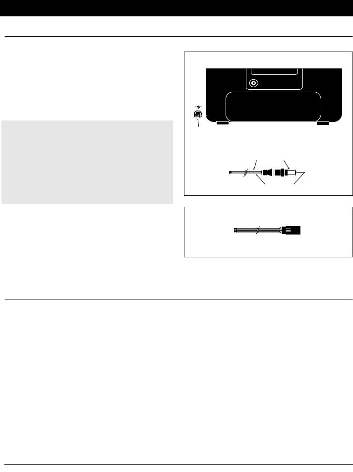
Transmitter Polarity
The center pin on all JR Remote Control Systems is negative. Therefore, the center pin on all JR chargers is negative, not positive. This is different from many other manufacturers’ chargers and radio systems. Beware of improper connections based on “color coded” wire leads as they do not apply in this instance. You must make sure that the center pin of your JR transmitter is always connected to the negative voltage for correct polarity hookup.
Transmitter |
|
|
Back of Transmitter |
|
D.S.C |
|
TRAINER |
|
CHARGE |
(–) |
(+) |
|
Center pin |
|
is negative |
Outside is |
|
positive |
|
|
Charger Pigtail for Transmitter |
|
Black to positive |
|
Red to negative |
Receiver |
|
Charger Pigtail to Receiver
Red |
= Positive |
Brown |
= Negative |
Orange = Signal
4.2 Charger
The pilot lamps should always be ON during the charging operation. If they’re not, check to make sure that both the transmitter and receiver are switched OFF.
Do not use this charger for equipment other than JR. The charging plug polarity may not be the same and equipment damage can result.
Do not use other manufacturers’ after-market accessories that plug into the transmitter’s charging jack. If you do, any damage that results will not be covered by the warranty. If you are unsure
of compatibilities with your radio, seek expert advice before doing anything to avoid possible damage.
During the charging operation, the charger’s temperature is slightly elevated. This is normal. Also, note that the voltage shown on the charger is higher than the battery in use. This voltage cannot be measured with a voltmeter. Only current can be measured with any accuracy using this type of charger.
Be sure to use the proper charge rate (120 mA) when using battery packs of 1000 mAh or larger for your receivers.
XP8103 14

5.General Information
5.1Control Stick Length Adjustment
The XP8103 allows you to adjust the control sticks’ length.
Note: Turn the wrench counterclockwise to loosen the screw. Then, turn the stick clockwise to shorten or counterclockwise to lengthen.
 Loosen
Tighten
To adjust the stick length, use the 2 mm Allen wrench (supplied with your XP8103 transmitter) to unlock the set screw.
After the control stick length has been adjusted to suit your flying style, tighten the 2 mm set screw.
If you desire longer sticks, JR offers a thicker stick (JRPA047) that is approximately one inch longer than the standard stick. This stick, crafted from bar stock aluminum, is available at your local JR dealer.
5.2 Control Stick Tension Adjustment
Remove the transmitter RF module, Nicad battery, and six (6) transmitter back cover screws. Remove the transmitter back, being careful not to bend or damage the RF module pins. Adjust each screw for the desired tension (counterclockwise to loosen
stick feel, clockwise to tighten stick feel). When adjusting the throttle ratchet tension, make sure the adjusting screw does not touch the PC board after the adjustment is complete.
Elevator Tension Screw |
Rudder Tension Screw |
|
Aileron Tension Screw
Throttle Tension Screw
XP8103 15
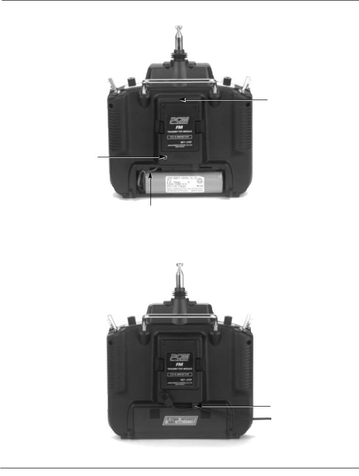
5.3 Transmitter Rear
DSC/Trainer Jack
Charging Jack for Nicad Battery Only (8N600S)
Battery Cover (Removed)
Caution: The battery connector is keyed so that it can only be plugged in in one direction. Do not force.
Transmitter Module
When the transmitter module is removed, you will find that the fuse is located at the bottom of the module cavity for easy replacement.
Cord Hook
When a trainer cord is used, place the cord between this hook and the transmitter body to avoid possible cord detachment during use.
XP8103 16

5.4 DSC Cord
For proper DSC hook up and operation:
1.Leave the transmitter power switch in the OFF position. The transmitter will not transmit any radio frequency (RF) in this position.
2.Plug the DSC cord (optional) into the DSC port in the rear of the transmitter.
3.The encoder section of the transmitter will now be operational and the LCD display will be lit.
4.Plug the other end of the DSC cord into the receiver charge receptacle. Turn the switch harness to the ON position.
Note: The DSC function will only operate with the JRPA001 Deluxe Switch Harness, or the JRPA004 Charge Switch.
When you install the charging jack, be sure to hook the charging jack receptacle securely into the switch harness charge cord.
Why you should use the DSC function:
1.The DSC enables you to check the control surfaces of your airplanes without drawing the fully operational 200 mAh from your transmitter battery pack. Instead, you will only draw 70 mAh when using the DSC function.
2.The DSC function allows you to make final adjustments to your airplane without transmitting any radio signals. Therefore, if another pilot is flying on your frequency, you can still adjust your airplane and not interfere with the other pilot’s aircraft.
Note: Under no circumstances should you attempt to fly your airplane with the DSC cord plugged in! This function is for bench checking your airplane only.
B |
A. Charge cord/DSC receptacle |
|
B. Switch harness lead |
||
A |
||
|
C. Charge cord/DSC lead |
|
|
C |
5.5 Neck Strap Adjustment
An eyelet is provided on the face of the XP8103 transmitter which allows you to connect a neck strap (JRPA023). This hook has been positioned so that your transmitter has the best possible balance when you use the neck strap.
Note: Double check to ensure that the neck strap is securely fastened to the transmitter.
5.6 Base Loaded Antenna
An optional base loaded antenna is available for use with the XP8103 transmitter. It is considerably shorter than the standard antenna. However, the base loaded antenna cannot be collapsed for storage in the side of the transmitter. You must also
use an adaptor (JRPA156) to attach the antenna to your XP8103. The base loaded antenna (JRPA155) is made of a flexible coil and is covered with a soft plastic material. Your range will not be affected when using the base loaded antenna.
XP8103 17

5.7 Frequency Notes/Aircraft Only Frequencies
The XP8103 employs a plug-in module system for transmitter frequency changes. If you want to change a frequency, you can simply change the radio frequency (RF) module, commonly referred to as either an RF module or transmitter module. The JR modules are universal for all modular frequency controlled systems. In other words, if you currently own a modular JR system, you can use the RF module from your current system with the XP8103.
The XP8103 can transmit in either Pulse Code Modulation (PCM) or in Pulse Position Modulation (PPM, commonly referred to as FM). Be certain to observe the following guidelines:
1. Do not operate your transmitter when another transmitter is using the same frequency, regardless of whether the second transmitter is PCM, PPM (FM) or AM. You can never operate two transmitters on the same frequency simultaneously without causing interference to both receivers and crashing both aircraft.
2. For operation of your XP8103 with additional receivers, you should refer to the receiver compatibility chart. The chart is located in the Modulation Select Section of this manual.
(pg. 31)
Aircraft Only Frequencies
JR RF modules and receivers are available on 50, 53, and 72 MHz frequencies in the United States for use with model aircraft. Employing 72 MHz frequencies does not require a special operators license from the Federal Communications Commission (FCC). However, the 50 and 53 MHz frequencies require that you carry a Technician II license.
• A chart for all available frequencies is located on page 142 of this manual.
5.8 Lithium Battery Indicator/Backup Error Display
Lithium Battery Indicator
If the voltage level of the lithium battery drops below an acceptable level (2.2v), an “L” will appear and flash to the left of the model number. This indicates that the lithium battery will
no longer maintain program memory if the main battery is disconnected. When the flashing “L” appears on the screen, the system should be sent to the JR/Horizon Service Center for a lithium battery replacement.
"L" indicates lithium battery needs to be replaced
Alarm and Backup Error Display
All pre-programmed data is protected by a five-year lithium battery that guards against main transmitter battery failure. Should the lithium battery fail, the display will indicate 1 back up error regardless of the position of the ON/OFF switch. If this occurs, it will be necessary to replace the battery and reprogram all data. All transmitter programs will return to the factory default setting, and the data you have input will be lost.
When it becomes necessary to replace the lithium back-up battery, contact the JR/Horizon Service Center. Due to the possibility of extensive damage caused by improper removal or replacement, only the JR/Horizon Service Center is authorized to make the change.
JR/Horizon Service Center
4105 Fieldstone Road
Champaign, IL 61821
XP8103 18
5.9 Screen Contrast Adjustment
The screen contrast adjustment feature of the XP8103 allows the user to select the proper tint of the screen for improved clarity and visibility in all weather conditions and temperatures.
To increase the contrast (darken the screen), simply turn the
power switch ON and press the SEL and DATA + keys simultaneously. To decrease the contrast (lighten the screen), press the SEL and DATA - keys simultaneously.
5.10 Installation Requirements
It is extremely important that your radio system be correctly installed in your model. Here are a few suggestions on the installation of your JR equipment.
1. Wrap the receiver in protective foam rubber that is no less than 3/8 inch thick. Secure the foam to the receiver with #64 rubber bands. This protects the receiver in the event of a crash or a very hard landing.
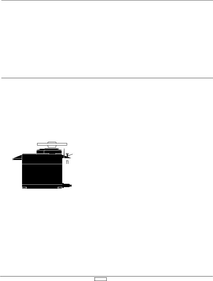
Servo Mounting Tab
Screw


 Rubber Grommet

 Brass Bushing
2. The servos should be mounted using rubber grommets and brass bushings to isolate them from vibration. Do not over-tighten the mounting screws — this will negate the vibration absorption effect of the rubber grommets. The diagram at left will assist you in properly mounting your servo.
The brass bushings are pushed from the bottom up in the rubber grommets. When the servo screw is tightened securely, it provides the proper security, as well as the proper vibration isolation, for your servo.
3.The servos must be able to move freely over their entire range of travel. Make sure that the control linkages do not bind or impede the movement of any of the servos.
4.Mount all switches away from the engine exhaust and away from any high vibration areas. Make sure each switch operates freely and is able to operate over its full travel.
5.Mount the receiver antenna firmly to the airplane to ensure that it will not become entangled in the propeller or control surfaces.
XP8103 19
XP8103 20

III. Airplane Section
ACRO 21

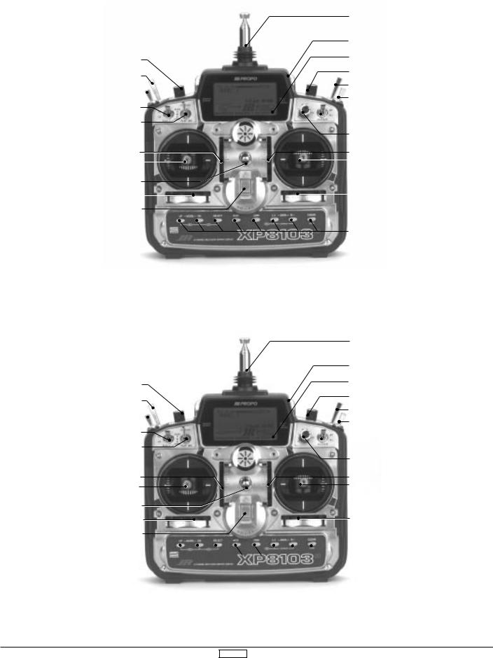
1. Transmitter Controls
1.1Control Identification and Location
Antenna
|
|
|
|
|
|
|
|
|
|
|
|
|
LCD Display (Do Not Press) |
Aux 2 Knob |
|
|
|
Carrying Handle |
|||||||||
|
|
|
|
||||||||||
Snap Roll/ |
|
|
|
Aux 3 Knob |
|||||||||
Timer/Trainer Switch |
|
|
|
P. Mix Switch/Aux 2 |
|||||||||
|
|
|
|
|
|
|
|
|
|
|
|
|
|
Gear Switch |
|
|
|
|
|
|
|
|
|
Rudder Dual Rate Switch |
|||
|
|
|
|
||||||||||
|
|
|
|
|
|
|
|
|
|
|
|
|
|
Elevator Dual Rate Switch |
|
|
|
|
|
Aileron Dual Rate Switch |
|||||||
|
|
||||||||||||
|
|
|
|
||||||||||
Flap/Mixing Switch |
|
|
|
Flap Knob |
|||||||||
|
|
|
|
||||||||||
Neck Strap Eyelet |
|
|
|
|
|||||||||
|
|
|
|
|
|
|
|
|
|
|
|
|
Elevator Trim |
|
|
|
|
|
|
|
|
|
|
|
|
||
Throttle/Rudder Stick |
|
|
|
|
|
|
|
|
|
|
|
|
Elevator/Aileron Stick |
|
|
|
|
|
|
|
|
|
|
|
|||
|
|
|
|
|
|
|
|
|
|
|
|
|
|
Throttle Trim |
|
|
|
|
|||||||||
Rudder Trim |
|
|
|
|
|
Aileron Trim |
|||||||
|
|
|
|
||||||||||
Power Switch |
|
|
|
|
|||||||||
|
|
|
|
|
|
|
|
|
|
|
|
|
Input Keys |
Channel Assignment/Throttle ALT |
|
Throttle ALT |
|||
Channel # |
TX Function |
Airplane Function |
The Throttle ALT function makes the throttle stick trim active only |
||
when the throttle stick is at less than half throttle. This gives easy, |
|||||
1 |
Thro |
Throttle Channel |
|||
accurate idle adjustments without affecting the high throttle |
|||||
2 |
Aile |
Aileron Channel |
|||
position. |
|||||
3 |
Elev |
Elevator Channel |
|||
|
|||||
4 |
Rudd |
Rudder Channel |
|
||
5 |
Gear |
Gear Channel |
|
||
6 |
Flap |
Auxillary 1 |
Channel (Flap) |
|
|
7 |
SPOI |
Auxillary 2 |
Channel (Spoiler) |
|
|
8 |
Aux 3 |
Auxillary 3 |
Channel |
|
|
ACRO 22
|
|
|
|
|
|
|
Airplane Version Transmitter – Heli Mode |
||||||||
|
|
|
|
|
|
|
|
|
|
|
|
|
|
|
Antenna |
|
|
|
|
|
|
|
|
|
|
|
|
|
|
|
Carrying Handle |
|
|
|
Pitch Trim Knob |
|
|
|
|
|
|
|
|
|
|
LCD Display – |
|
|
|
|
|
|
|
|
|
|
|
|
|
|
DO NOT PRESS |
||
|
|
|
Trainer/Timer Switch |
|
|
|
|
|
|
|
|
|
|
Hovering Pitch Knob |
|
|
|
|
|
|
|
|
|
|
|
|
|
|
|
||
|
|
|
|
|
|
|
|
|
|
|
|
|
|
|
Throttle Hold Switch |
|
|
|
Invert Switch |
|
|
|
|
|
|
|
|
|
|
Rudder Dual Rate Switch |
|
|
|
|
|
|
|
|
|
|
|
|
|
|
|||
|
|
|
|
|
|
|
|
|
|
|
|
|
|
|
|
|
|
Elevator Dual Rate Switch |
|
|
|
|
|
|
|
|
|
|
|
||
|
|
|
Flight Mode Switch |
|
|
|
|
|
|
|
|
|
|
Aileron Dual Rate Switch |
|
|
|
|
|
|
|
|
|
|
|
|
|||||
|
|
|
|
|
|
|
|
|
|
|
|
|
|
||
|
|
|
N-Normal Position |
|
|
|
|
|
|
|
|
|
|
|
|
|
|
|
1-Flight Mode 1 |
|
|
|
|
|
|
|
|
|
|
Hovering Throttle Knob |
|
|
|
|
2-Flight Mode 2 |
|
|
|
|
|
|
|
|
|
|
||
|
|
|
|
|
|
|
|
|
|
|
|
|
|
||
|
|
|
Throttle Trim |
|
|
|
|
|
|
|
|
|
|
Elevator Trim |
|
|
|
Throttle/Rudder Stick |
|
|
|
|
|
|
|
|
|
|
|
Aileron/Elevator Stick |
|
|
|
|
|
|
|
|
|
|
|
|
|
||||
|
|
|
|
|
|
|
|
|
|
|
|
|
|
||
|
|
|
Neck Strap Eyelet |
|
|
|
|
|
|
|
|
|
|
|
|
|
|
|
Rudder Trim |
|
|
|
|
|
|
|
|
|
|
Aileron Trim |
|
|
|
|
|
|
|
|
|
|
|
|
|
|
|||
|
|
|
|
|
|
|
|
|
|
|
|
|
|||
|
|
|
|
|
|
|
|
|
|
|
|
|
|
||
Channel Assignment |
Power Switch |
|
|
|
|
|
|
|
|
|
|
|
|||
|
|
|
|
|
|
|
|
|
|
|
|
|
|||
1. |
THRO |
Throttle Channel |
|
|
|
|
|
|
|
|
|
|
|
|
Input Keys |
2. |
AILE |
Aileron Channel |
|
|
|
|
|
|
|
|
|
|
|
|
|
|
|
|
|
|
|
|
|
|
|
|
|
|
|||
3. |
ELEV |
Elevator Channel |
|
|
|
|
|
|
|
|
|
|
|
||
4. |
RUDD |
Rudder Channel |
|
|
|
|
|
|
|
|
|
|
|
|
|
5. |
GEAR |
Gear Channel |
|
|
|
|
|
|
|
|
|
|
|
|
|
6.AUX 1 Auxiliary 1 Channel (Pitch)
7.AUX 2 Auxiliary 2 Channel
(Gyro Sensitivity)
8.AUX 3 Auxiliary 3 Channel
|
|
Airplane Version Transmitter – Glider Mode |
||
|
|
|
|
Antenna |
|
|
|
|
Carrying Handle |
|
|
|
|
LCD Display – |
Flaperon/Flap Trim Knob (Pot. 7) |
|
|
|
DO NOT PRESS |
Snap Roll/ |
|
|
|
Dual Flap Aileron Trim Knob (Pot. 5) |
Timer/Trainer Switch |
|
|
|
Mixing Switch |
|
|
|
|
|
Crow Switch |
|
|
|
Rudder Dual Rate Switch |
|
|
|
||
|
|
|
|
|
Elevator Dual Rate Switch |
|
|
|
|
Flap/Mixing Switch |
|
|
|
Aileron Dual Rate Switch |
|
|
|
||
|
|
|
|
|
|
|
Reflex |
|
|
■-Off |
|
|
Launch |
|
|
Spoiler Trim |
|
|
Spoiler/Rudder Stick |
|
|
Neck Strap Eyelet |
|
|
Rudder Trim |
|
|
Power Switch |
Channel Assignment |
||
1. |
SPOI |
Spoiler Channel |
2. |
AIL1 |
Left Aileron Channel |
3. |
ELEV |
Elevator Channel |
4. |
RUDD |
Rudder Channel |
5. |
AIL2 |
Gear Channel |
|
|
(Right Aileron Channel–AILE 2) |
6. |
FLAP |
Auxiliary 1 Channel |
|
|
(Left Flap Channel for Dual Flaps) |
7.AUX 2 Auxiliary 2 Channel
(Right Flap Channel for Dual Flaps)
8.AUX 3 Auxiliary 3 Channel
Flap Trim Knob (Pot. 6)
Elevator Trim
Aileron/Elevator Stick
Aileron Trim
 Input Keys
ACRO 23
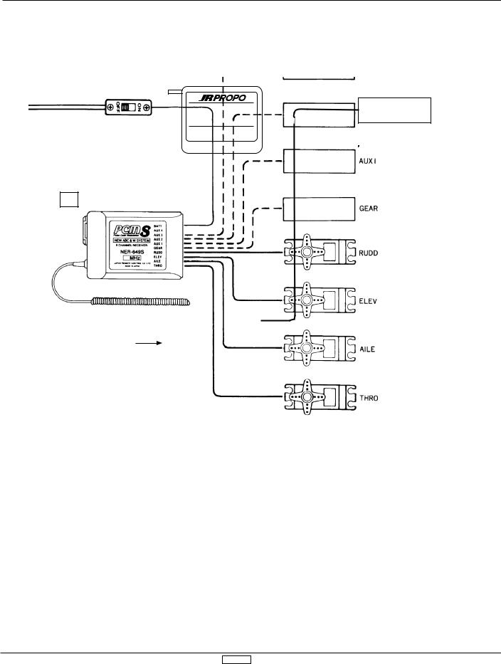
1.2 Connections
® |
|
|
|
4N600 |
Aux Channel |
not |
|
used |
|||
|
|||
|
|
||
4.8V 600mAh |
|
|
|
JAPAN REMOTE CONTROL CO., LTD. |
|
|
Aux Channel
Spoiler Channel
Charge Cord or DSC |
Deluxe Switch Harness |
Receptacle |
(JRPA001) |
(JRPA024) |
|
Flap Channel
Retract
Gear Channel
NER-649S
S-PCM Receiver
(JRPR649) |
72 |
|
|
PCM Version |
|
NER-549S |
|
FM Receiver |
|
(JRPR549) |
|
FM Version |
|
ACRO 24

2. General Information
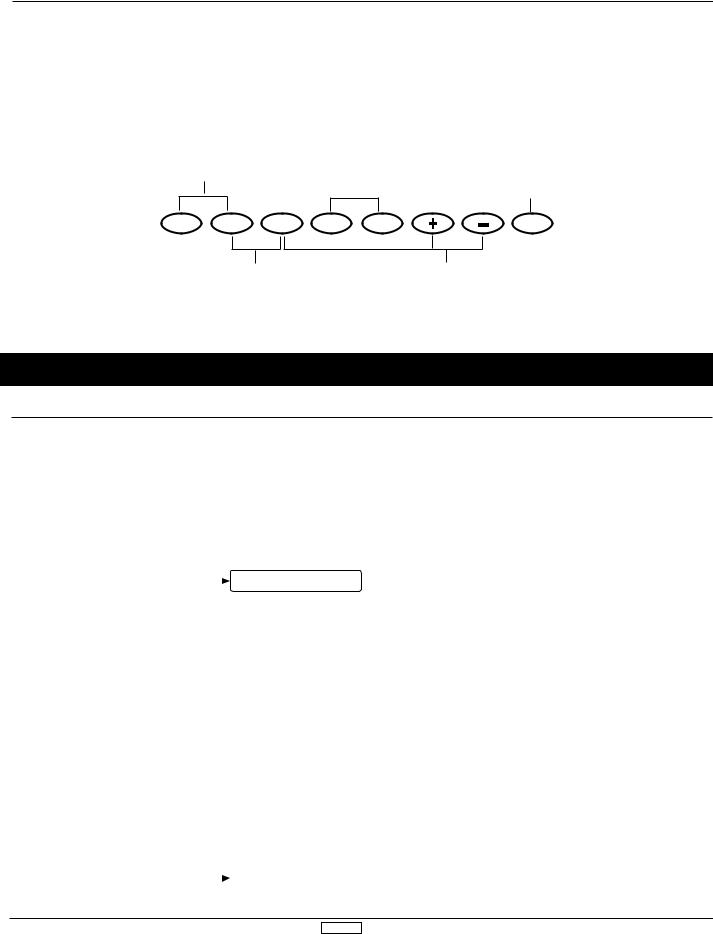
2.1 Input Key Functions
•You will hear a clicking (beeping) sound to confirm input has been achieved.
•Except for the CLEAR key, the AUTO advance system (two speed scrolling) is active when you continue pressing down on a key.
• The SEL keys or CH keys are used to scroll through, or manipulate functions within a specific program or display.
Down Key
Up Key
Function Selection keys (press both keys simultaneously to enter or exit the function mode)
Select Key |
Channel Key |
Increase Key |
Decrease Key |
|
|
||||
|
|
|
|
|
|
|
|
|
Clear Key |
|
|
|
|
|
|
|
|||
|
|
|
|
|
|
R/- |
|
CLEAR |
|
SELECT |
|
|
L /+ |
|
|||||
|
|
|
|
|
|
|
|
|
|
|
|
|
|
|
|
|
|
|
|
|
|
|
|
|
|
|
|
|
|
Data Entry Keys
used for channel changes in the model set-up and function modes
used for changing pages or indicated displays
Press both keys simultaneously to access the system mode or function mode lists.
2.2 Normal Display
|
Normal Display Screen |
transmitter voltage |
modulation type |
model number |
model name (when |
|
names are entered) |
|
integrated timer |
ACRO 25
2.2 Normal Display, cont.
From the Normal Display, the following inputs can be made:
When setting various functions with the buttons shown below, start either in the Function Mode or the System Set-Up Mode.
Press the UP and DN keys simultaneously and switch the power from OFF to ON to change the system to the System Set-Up Mode
Press the UP and DN keys |
|
|
|
simultaneously to change |
|
|
|
to Function Mode (with |
|
|
|
power switch ON) |
UP |
DN |
SELECT |
|
When timer function is active, use CH key to start/stop timer
 CH CH
CH CH
Press the Clear key to reset to factory settings
CLEAR
Press simultaneously to access the List
Mode/System Set-Up Mode
Press Select and either the + or - keys simultaneously to adjust the contrast of the LCD display
3.System Set-Up Mode Functions
3.1System Set-Up Mode
To set the System Set-Up Mode, press the UP and DN keys simultaneously and turn the power switch from OFF to ON. Functions are selectable by pressing either the DN or UP keys. Individual settings are explained later at each function. In this mode, servos are not activated, but operating signals are
transmitting (only when the Tx module is in place). However, use extra caution not to interfere with other frequencies. By pressing the DN and UP keys simultaneously, you can return to the normal display, which allows the servos to again operate.
SYSTEM SET-UP MODE
Use either the UP |
|
[INFO-DISP] |
Pg. 28 |
Information Display |
or DN key to scroll |
|
|||
|
|
↕ |
|
|
through the menu |
|
|
|
|
and access the |
|
|
Pg. 29 |
Model Select and Copy |
applicable function |
|
|
||
|
|
|
|
|
|
|
|
Pg. 29 |
Model Name Input |
|
|
|
Pg. 30 |
Model Type Selection Function |
|
|
|
Pg. 30 |
Data Reset |
|
|
|
Pg. 31 |
Modulation Selection |
|
|
|
Pg. 32 |
Data Transfer between traqnsmitters |
|
|
|
Pg. 34 |
Wing Type Selection |
|
|
|
Pg. 35 |
Spoiler Channel Input Selection |
|
|
|
ACRO 26

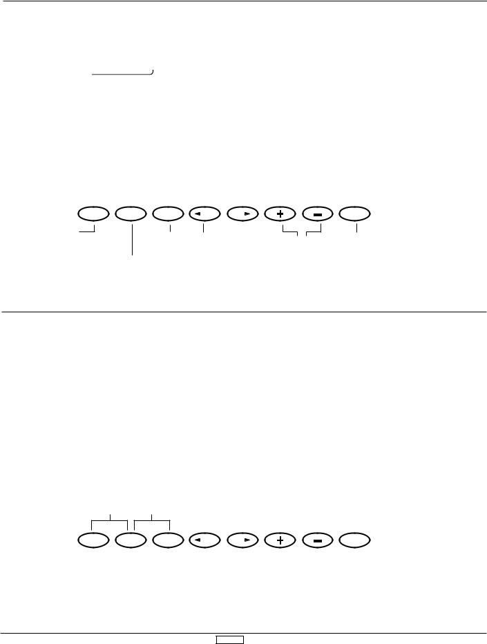
3.2 Function Mode
From Normal Display, press the UP and DN keys simultaneously to enter the Function Mode. In this mode, by using the UP or DN keys, the desired functions can be selected. When channel selection or an additional function change is desired, use the CH keys or SEL key. For example, Dual Rate Function is selected and the elevator channel is displayed by pressing the UP key once; the function is changed to the next mode, Reverse Switch, but the channel is still displayed as elevator.
Function Mode Flowchart
Information pertaining to each function is explained on the page number listed next to the function name. Functions will appear on the screen in the same order they are shown on the flow chart below:
Use either the UP or DN key to scroll through the menu and access the applicable function
Therefore, by scrolling through the program, you can adjust each function related to the elevator channel quickly and easily.
To Access The Function Mode
1.Switch the power switch to the ON (upper) position.
2.Press the UP and DN keys simultaneously.
3.Use either the UP or DN keys to scroll through the menu and access the appropriate function.
Pg. 36 |
Dual Rate, Exponential |
Pg. 38 |
Reverse Switch |
Pg. 38 |
Sub-Trim |
Pg. 39 |
Travel Adjust (end point adjustment) |
Pg. 39 |
Elevator to Flap Mixing |
Pg. 40 |
Aileron to Rudder Mixing |
Pg. 41 |
Landing System |
Pg. 42 |
Snap Roll |
Pg. 44 |
Differential Aileron Mixing (only if flaperon or |
|
elevons mixing is active) |
Pg. 45 |
Trim Offset Memory |
Pg. 46 |
Flap Knob Operating Value Adjustment |
Pg. 47 |
Programmable Mixing 1 |
Pg. 47 |
Programmable Mixing 2 |
Pg. 47 |
Programmable Mixing 3 |
Pg. 47 |
Programmable Mixing 4 |
Pg. 47 |
Programmable Mixing 5 |
Pg. 47 |
Programmable Mixing 6 |
Pg. 50 |
Fail-Safe/Hold (PCM Only) |
Pg. 52 |
Trainer |
Pg. 54 |
Timer |
Pg. 55 |
Servo Output Values |
ACRO 27
3.3 List Mode (Function Mode)
To enter the List Mode, press the DN and SEL keys simultaneously. From this display, pressing the UP and DN keys simultaneously will move the system from the list mode to the
function shown at the cursor. Note that the cursor is moved by the UP and DN keys.
Press simultaneously |
|
|
|||
to access function at |
Press to select either of |
||||
cursor |
two Function List screens |
||||
|
|
|
|
|
|
|
|
|
|
|
|
|
|
|
|
|
|
UP |
DN |
SELECT |
CH |
CH |
CLEAR |
|
|
|
|
|
Inactive while in List Mode screen |
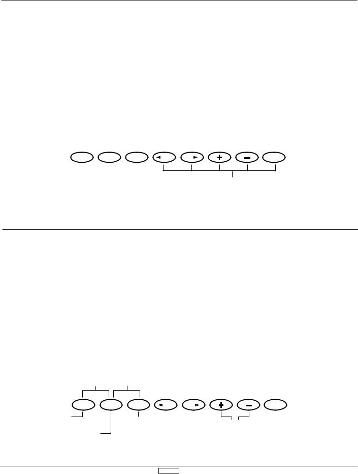
3.4 Model Select (System Set-Up Mode)
The XP8103 transmitter employs a memory function which memorizes data for up to 10 individual aircraft. All settings along with type selection, function, and different aircraft are used by one transmitter. For example, Model 1 is helicopter and Model 2 is airplane. To avoid confusing models, inputing model
names for each aircraft is recommended (see page 29). Press the UP and DN keys simultaneously and turn the power switch ON to access the System Set-Up Mode.
The display below shows the model selection function.
model number (1-10)
Press UP and DN keys simultaneously to exit the System Set-Up Mode
Press UP and Select keys simultaneously to access the System Mode info display
model name
(if dot is shown, model name is blank)
modulation
type
UP |
DN |
SELECT |
CH |
CH |
CLEAR |
To Model Name function
Function select
To Info Display function
(select model/copy) Model selection (1-10)
ACRO 28
3.5 Copy Select Function (System Set-Up Mode)
The Copy Select Function enables you to copy all of the settings of your current model to another memory (model number) within
the same transmitter. This is very useful when setting up one aircraft several different ways.
existing model number
model number to be transferred to.
Press UP and DN keys |
Press the Select key to |
|||||||
simultaneously to exit the |
||||||||
access the copy function |
||||||||
System Set-Up Mode |
||||||||
in Model Select mode |
||||||||
|
|
|
|
|
|
|||
|
|
|
|
|
|
|
|
|
|
|
|
|
|
|
|
|
|
model names
(if dot is shown, model name is blank)
UP |
DN |
SELECT |
CH |
CH |
CLEAR |
To Model Name function
|
|
Function select |
Model selection — |
Activate copy |
|
|
(select model/copy) |
||
To Spoiler Channel input |
|
use to select model |
function |
|
|
|
|||
|
|
to be copied to |
|
|
selection function |
|
|
|
|
|
|
|
|
3.6 Model Names (System Set-Up Mode)
This function is used to input model names individually. Each model’s name is displayed in the normal screen automatically. when that model is selected. To avoid confusing models, inputing model names is recommended. You can input a
model number
modulation
maximum of 8 characters for each model name.
In the System Set-Up Mode, select the Model Name Function using the UP or DN key. Once selected, simultaneously press the UP and DN keys to access.
model type
letter position being inputed (8 characters)
Press UP and DN keys simultaneously to exit the System Set-Up Mode
Press the DN and Select keys simultaneously to access the System Mode info display
UP |
DN |
SELECT |
CH |
CH |
CLEAR |
To Model Type Selection |
|
|
|
|
|
|
|
|
|
|
|
|
|
|
|
|
|
|
|
function |
Press to change |
Press to change |
Changes input letter |
||||||||||||||||
|
|
|
|
||||||||||||||||
To Model Select/Copy |
|
input letter arrow |
input letter at arrow |
to blank space only |
|||||||||||||||
|
position |
|
|
|
|
|
|
|
where arrow is |
||||||||||
|
|
|
|
|
|
|
|
||||||||||||
function |
|
|
|
|
|
|
|
|
|
|
|
|
|
|
located |
||||
ACRO 29
 Loading...