


U S E R M A N U A L
H E L I C O P T E R
V E R S I O N

Table of Contents
Using This Manual
JR’s PCM10X offers the ultimate in programming capability while still retaining the “user friendliness” for which JR’s original PCM10, 10S, 10Sx, and 10SxII systems are known. While many of the screens are similar to the previous generation systems, it’s important that you read and understand this manual to fully appreciate and take advantage of the capabilities of the features available with the PCM10X.
Your new JR PCM10X is also equipped with JR’s new innovative 3+1 Digital Trim System. These new 3+1 Digital Trims offer the best of both worlds—digital trim levers on aileron, elevator, and rudder for maximum efficiency and precision, while retaining the mechanical trim on the throttle for safety and immediate visual reference.
Refer to the Table of Contents below to find out where to look for answers to your particular questions. The features are discussed in the same order as they appear on the LCD of your screen (numerically). An explanation of the use and purpose of each feature is provided, followed by a labeled illustration of its LCD display. Additionally, a step-by-step example is included to clarify the set-up procedure of the feature.
You will find a blank data sheet at the end of this manual. Once you have entered all data for a particular model, we recommend that you also record it on the data sheet. If you should experience a memory battery failure or wish to make changes to the current settings, this extra step will save you a lot of time.
1. |
Features |
3 |
|
8.3 |
Code 13 Dual Rate/Exponential Adjustments. . . . . . . . . . . |
. . 17 |
||
|
1.1 |
Transmitter |
3 |
|
8.4 |
Code 15 Sub-Trim Adjustment . . . . . . . . . . . . . . . . . . . . . . . |
. 20 |
|
|
|
8.5 |
Code 16 Throttle Hold |
21 |
||||
|
1.2 |
Receiver |
4 |
|
||||
|
|
8.6 |
Code 17 Function Select |
23 |
||||
|
1.3 |
Servos |
4 |
|
||||
|
|
8.7 |
Code 18 Throttle Curve |
25 |
||||
|
1.4 |
Optional High Performance Tail Rotor Servos |
4 |
|
||||
|
|
8.8 |
Code 23 Automatic Dual Rate |
29 |
||||
|
1.5 |
Optional Gyro Selection |
4 |
|
||||
|
|
8.9 |
Code 28 Data Reset |
30 |
||||
2. |
Component Specifications |
6 |
|
|||||
|
8.10 |
Code 41 Rudder Throttle Mixing . . . . . . . . . . . . . . . . . . . |
. 31 |
|||||
|
2.1 |
System Specifications . . . . . . . . . . . . . . . . . . . . . . . . . . . . . . |
. . 6 |
|
8.11 |
Code 42 Aileron Throttle Mixing . . . . . . . . . . . . . . . . . . |
. 32 |
|
|
2.2 |
Transmitter Specifications. . . . . . . . . . . . . . . . . . . . . . . . . . . |
. . 6 |
|
8.12 |
Code 43 Elevator Throttle Mixing . . . . . . . . . . . . . . . . . . |
. 33 |
|
|
2.3 |
Servo Specifications . . . . . . . . . . . . . . . . . . . . . . . . . . . . . . . |
. . 6 |
|
8.13 |
Code 44 Gyro Sensitivity Adjustment. . . . . . . . . . . . . . . . . . |
. 34 |
|
|
2.4 |
Receiver Specifications . . . . . . . . . . . . . . . . . . . . . . . . . . . . . |
. . 6 |
|
8.14 |
Code 47 Tail Rotor Curve . . . . . . . . . . . . . . . . . . . . . . . . . . . |
. 36 |
|
|
2.5 |
Charger Specifications . . . . . . . . . . . . . . . . . . . . . . . . . . . . . |
. . 6 |
|
8.15 |
Codes 51-54 Standard Programmable Mixing . . . . . . . . . . . |
. 40 |
|
|
2.6 |
Airborne Battery Pack . . . . . . . . . . . . . . . . . . . . . . . . . . . . . . |
. . 6 |
|
8.16 |
Codes 55-58 Multi-Point Programmable Mixing . . . . . . . . . |
. 43 |
|
3. |
Transmitter Controls |
7 |
|
8.17 |
Code 65 Swashplate Mixing/Type . . . . . . . . . . . . . . . . . . . . |
. 46 |
||
|
8.18 |
Code 68 Pitch Curve Function |
49 |
|||||
|
3.1 |
Control Identification, Location and Channel Assign |
7 |
|
||||
|
|
8.19 |
Code 75 Servo Monitor |
53 |
||||
|
3.2 |
Transmitter Rear |
8 |
|
||||
|
|
8.20 |
Code 77 Fail-Safe/Hold |
54 |
||||
|
3.3 |
Stick Length Adjustment |
8 |
|
||||
|
|
8.21 |
Code 81 Model Name |
57 |
||||
|
3.4 |
Neck Strap Attachment |
8 |
|
||||
|
|
8.22 |
Code 82 Trim Offset |
58 |
||||
|
3.5 |
Adjustment of Stick Tension |
8 |
|
||||
|
|
8.23 |
Code 83 Digital Trims and Trim Rate Adjustment |
59 |
||||
|
3.6 |
Using the DSC Cord |
9 |
|
||||
|
|
8.24 |
Code 84 Model Selection |
61 |
||||
|
3.7 |
Frequency Notes/Aircraft Only Frequencies |
9 |
|
||||
|
|
8.25 |
Code 85 Modulation Selection (SPCM, ZPCM, PPM) |
63 |
||||
4. |
Connections |
10 |
|
|||||
|
8.26 |
Code 86 Data Transfer . . . . . . . . . . . . . . . . . . . . . . . . . . . . . |
. 64 |
|||||
|
4.1 |
Installation Requirements . . . . . . . . . . . . . . . . . . . . . . . . . . . |
. 10 |
|
8.27 |
Code 87 Timer . . . . . . . . . . . . . . . . . . . . . . . . . . . . . . . . . . . . |
. 67 |
|
|
4.2 |
Connections. . . . . . . . . . . . . . . . . . . . . . . . . . . . . . . . . . . . . . |
. 10 |
|
8.28 |
Code 88 Keyboard Lock . . . . . . . . . . . . . . . . . . . . . . . . . . . . |
. 68 |
|
5. Display and Touch Panel |
11 |
9. |
Battery Charging |
69 |
||||
|
5.1 |
Care of the Touch Screen . . . . . . . . . . . . . . . . . . . . . . . . . . . |
. 11 |
|
9.1 |
Transmitter /Receiver . . . . . . . . . . . . . . . . . . . . . . . . . . . . . . |
. 69 |
|
|
5.2 |
Operating the Touch Panel . . . . . . . . . . . . . . . . . . . . . . . . . . |
. 11 |
|
9.2 |
Charger . . . . . . . . . . . . . . . . . . . . . . . . . . . . . . . . . . . . . . . . . |
. 69 |
|
6. Alarm & Error Display |
11 |
10. |
Servo Precautions |
70 |
||||
|
6.1 |
Battery Alarm . . . . . . . . . . . . . . . . . . . . . . . . . . . . . . . . . . . . |
. 11 |
11. |
General Notes/Safety Precautions |
70 |
||
|
6.2 |
Back Up Error Alarm . . . . . . . . . . . . . . . . . . . . . . . . . . . . . . |
. 12 |
12. |
Federal Aviation Administration |
71 |
||
|
6.3 |
Switch Position Warning Message |
12 |
|||||
|
13. |
Daily Flight Checks |
71 |
|||||
|
6.4 |
All Servo Hold Function: Main Screen . . . . . . . . . . . . . . . . |
. 12 |
|||||
7. |
Data Input |
13 |
14. |
Frequency Chart |
72 |
|||
15. |
Use Of A Gyro |
72 |
||||||
|
7.1 |
Code Number Access . . . . . . . . . . . . . . . . . . . . . . . . . . . . . . |
. 13 |
|||||
|
7.2 |
Direct Mode. . . . . . . . . . . . . . . . . . . . . . . . . . . . . . . . . . . . . . |
. 13 |
16. |
Warranty Information |
73 |
||
8. |
Code Functions |
14 |
17. |
Data Sheets |
74 |
|||
|
8.1 |
Code 11 Reversing Switches. . . . . . . . . . . . . . . . . . . . . . . . . |
. 15 |
|
|
|
|
|
|
8.2 |
Code 12 Travel Adjust/ATV/End Point Adjust . . . . . . . . . . . |
. 16 |
|
|
|
|
|
2 |
|
|
|
|
|
10X MANUAL Heli |
||

1 Features
1.1Transmitter
•Up to 5 available flight modes are selectable via a programmable switch location. Each flight mode allows the adjustment and selection of nearly every parameter to alter the characteristics of the helicopter for differing flight regimes (e.g., FAI type aerobatics, 3D aerobatics, etc.). Code 17.
•Digital trims on aileron, elevator and rudder feature adjustable trim rates, allowing the increments of each trim step to be adjusted to the desired amount. When adjusting the digital trims, a tone is emitted that signals each trim step. The pitch of the tone changes based on trim position (left trim – high pitch, right trim – low pitch ) so that the approximate trim position can be audibly known without having to look at the transmitter.
•Digital trim positions are automatically displayed on the Info screen. A bar graph or a digital value can be selected to display the trim position.
•Digital trim positions are automatically stored in memory and recalled when switching from model to model.
•A mechanical trimmer is included on throttle, offering the ease and convenience of a visual reference during engine startup. The throttle trim rate is adjustable in Code 83.
•A DataSafeTM is included (complete systems only) that
allows the 10X to download model memory to any Windows 95® and later PC for infinite model storage and security. See the enclosed Data-Safe manual for instructions.
•A removable 1100mAh Sanyo® battery pack gives nearly 5 hours of continuous use. A built-in charge receptacle allows the battery to be charged separately or in the transmitter.
•Rudder-to-throttle mixing has separate adjustable values left and right and can be activated in any or all flight modes.
•Aileron-to-throttle mixing has separate adjustable values right and left and can be activated in any or all flight modes.
•Elevator-to-throttle mix has separate adjustable values up and down and can be activated in any or all flight modes.
•Gyro gain function, Code 44, allows you to combine rudder to Aux 3 mixes to Code 44 (gyro gain adjustment), allowing stick priority gain control. Stick priority gain values are also displayed on this screen.
•Five programmable tail rotor curves are available that allow up to 7 points to be stored. The mix rate function allows the tail curve to be expanded (1/1, 1/2, 1/4, 1/10) for a more accurate tail adjustment.
•Swashplate mixing features independent aileron-to-elevator and elevator-to-aileron mixing values and can be activated in any or all fight modes. 120° and 140° 3 servo CCPM mixing is also available.
•A servo monitor visually displays each of the ten servo positions. This handy feature is especially useful during the setup of mixes. CODE 75.
•The programming of the PCM10X allows up to five flight modes with independent throttle and pitch curves, tail rotor curve mixing, and pre-programmed Aile/Elev/Rudd-Throttle mixing.
•An exponential function is available on the throttle and pitch curves that automatically “smoothes out” the curve.
•When using the PCM10X in conjunction with a JR Piezo Gyro, three gyro rates are available and can be selected in the six types of flight modes (N, 1, 2, 3, 4, Hold).
•The micro computer system employs an extra large and clearly visible LCD touch display that makes the PCM10X the fastest and easiest radio control transmitter system in the world to program.
•Adjustable stick tension enables you to customize the feel of the gimbals for more precise flying. Refer to Section 3.5 of this manual for instructions on adjusting stick tension.
•The new central processing unit (CPU) in the PCM10X allows for compatibility never before available in any radio system. This transmitter can broadcast in two types of PCM— the new S-series (1024) PCM and the well-known Z-series (512) PCM
—as well as PPM. This enables you to use virtually all of your current FM JR receivers.
•The PCM10X is capable of storing ten (10) models in its memory. The ten (10) model memory allows you to completely program ten models into the PCM10X. Or, by using more than one program for a single aircraft, you are able to have different set-ups available.
•The PCM10X is equipped with a five-year lithium battery back-up to prevent memory loss if your transmitter battery pack should discharge completely or if the transmitter battery pack should inadvertently be removed from the transmitter.
•A fail-safe feature when modulating in the S-series PCM allows you to select hold or fail-safe preset positions for the first eight channels individually.
•Direct Servo Control (DSC) permits operation of all controls and servos without generating a radio signal.
•The graphic multi-point pitch and throttle curve means you can set the pitch for 7 selectable stick positions.
•The PCM10X offers a choice of dual rate, exponential or variable trace rate (VTR) movement for the aileron, elevator and rudder channels.
•The PCM10X has eight free programmable mixes, four of which allow the programming of up to a seven point curve that can be turned on/off in any flight mode.
10X MANUAL Heli |
3 |

1.2Receiver
•The NER 950S receiver is a high performance PCM single conversion receiver with 10 KHz super narrow band ABC+W circuitry, offering an unparalleled RF link.
•The latest “S” type Central Processing Unit (CPU) is used in the PCM receiver. It has the highest degree of resistance to electro-mechanical “noise.”
•A narrow band ceramic filter for high signal selectivity also assists in rejecting cross modulation from other common radio frequency difficulties, such as R/C transmitters or local paging systems.
•The receiver features Direct Servo Control (DSC) for control of surfaces without radio frequency output.
•The Central Processing Unit (CPU) improves signal reception and integrated fail-safe feature.
•The new NER-950S offers the highest resolution available in any receiver.
•The receiver has low current consumption.
•The receiver features 3-point gold plated connectors for increased conductivity.
1.3Servos
DS8231 Digital
•The DS8231 features wide spaced dual ball bearings designed to endure the high vibration environments commonly associated with many radio control models.
•A high frequency digital amplifier offers up to 5 times greater holding torque than a conventional servo
•Super-tight deadband of .06 µs for superior accuracy
•Up to 5 times more holding torque than a conventional servo with less than a 10% increase in current drain
•High output F.E.T. transistor driven motor
•High resolution of 5,900 steps per 120°
•13 bit A/D converter
1.4Optional High Performance Tail Rotor Servos
To obtain the highest performance levels from your tail rotor/ gyro system, great care and consideration must be taken in the selection of the servo to be used.
In general, the quicker the transit time and the more accurate the centering abilities of the servo, the better the gyro will perform.
If a servo with a slow transit time is used (more than .24 sec/60º), in actuality the gyro system, especially a Piezo unit, may become too quick for the servo, resulting in a “wag” or “hunting” situation which would require the user to reduce the percentage of gain to compensate for this deficiency. This reduction in gain would also reduce the holding power and, therefore, the performance of your gyro system.
The following optional JR servos are recommended specifically for use on the tail rotor:
Standard |
Transit |
Super |
Transit |
Servo |
Time |
Servo |
Time |
JRPS4735 |
.15 sec/60º |
JRPS2700G |
.09 sec/60 |
|
|
|
|
Digital Servo |
|
|
|
|
|
|
|
JRPS8417 |
.10 sec/60° |
|
|
|
|
|
|
1.5Optional Gyro Selection
The following gyro systems are highly recommended for use with the PCM10X system. Each of these gyros is designed to make full use of the Code 44 gyro sensitivity adjustment feature of this system.
JR NEJ-450 Piezo Gyro (Intermediate/Advanced)
Features
•Integrated design for easy installation/connection
•No moving parts for a nearly unlimited service life
•Linear dynamic range up to 720 degrees per second
•10 times faster response time than mechanical gyros
•Remote proportional gain control adjustable from the transmitter
•Patented offset drift canceler
Specifications
Operating Voltage: |
|
4.8V |
Operating Current: |
|
40 mA |
Dimensions/Weight: |
1.45"x1.10"x1.42"/11/4 oz. |
|
Gyro Sensor: |
|
40x42x36mm/56g |
Remote Gain Controller: |
30x22x9mm/8g |
|
Dynamic Range: |
|
0–720° per second |
JR’s latest Piezo gyro, the NEJ-450, utilizes a new state-of-the- art integrated design for easy installation, while retaining the same performance levels found in the previous JR NEJ-900 Piezo gyro.
4 |
10X MANUAL Heli |
Unlike standard mechanical type gyros that use a motor, flyweights, bearings, etc., the NEJ-450 Piezo gyro system is totally free of moving parts that in time wear out, giving the NEJ-450 a nearly unlimited service life.
The NEJ-450 offers a true linear response of up to 720 degrees per second. The NEJ-450 is also 10 times more sensitive and has a faster response time than any current mechanical type gyro, making it one of the highest performance gyros available.
JR NEJ-3000 Piezo Gyro (Advanced/Expert)
Features
•M.P.C. (Multi Pulse Control) System—The high frequency output pulse of the NEJ-3000 is three times faster than existing electronic gyros for unmatched performance.
•Over-travel limiters prevent servo over-stroke.
•A built-in remote gain controller allows gain adjustment from the transmitter.
•Newly developed offset drift canceling circuitry.
•Solid state design with no moving parts for an almost infinite lifetime.
•Linear dynamic range up to 720 degrees per second.
Specifications
Operating Voltage; |
4.8 |
Operating Current: |
50 mA (gyro only) |
Dimensions: |
|
Gyro Sensor: |
33 x 33 x 35mm |
Amplifier: |
38 x 18 x 53mm |
Weight: |
|
Gyro Sensor: |
1.3 oz |
Amplifier: |
1.1 oz |
JR’s NEJ-3000 Piezo Electronic Gyro System represents the latest in technological advancements. The NEJ-3000, combined with JR’s 2700G Super Servo, offers superior “holding power” in all conditions, unequaled by any other gyro system. Its advanced M.P.C. (Multi Pulse Control) System has a high frequency output that allows the NEJ-3000 to react up to three times faster than existing electronic gyros.
Important: JR’s NEJ-3000 must be used in conjunction with JR’s 2700G Super Servo. JR’s 2700G Super Servo features an ultra quick response and transit time, and its total servo stroke (throw) is specifically matched to give the best possible resolution when used with the NEJ-3000 Piezo Gyro. The 2700G Super Servo features a metal gear train—standard plastic gears can strip because of quick changes in servo direction/velocity when hooked to the NEJ-3000 Gyro.
10X MANUAL Heli |
5 |

2 Component Specification
2.1System Specifications
. . . . . . . . . . . .System Name |
J120HS Computer Helicopter |
|
System |
Transmitter (Main Body) . . |
NET-J120HS |
(RF Module)NET-J72P, NET-J50P, NET-J53P |
|
Receiver . . . . . . . . . . . . . . . . |
NER-950S |
Servos . . . . . . . . . . . . . . . . . |
DS-8231 Digital |
Charger . . . . . . . . . . . . . . . . |
NEC-222 |
Airborne Battery. . . . . . . . . . |
1400 mAh Sanyo Extra® NiCad |
2.2Transmitter Specifications
. . . . . . . . . . . . . . .Model No |
NET-J120HS |
Encoder . . . . . . . . . . . . . . . . |
10 Channel Computer System |
RF Module. . . . . . . . . . . . . . |
50/53/72 MHz |
Modulation . . . . . . . . . . . . . |
PCM (S&Z) or PPM |
Output Power. . . . . . . . . . . . |
Approximately 750 mw |
Current Drain. . . . . . . . . . . . |
200 mA (70 mA w/DSC) |
Power Source. . . . . . . . . . . . |
1.2V x 8 NiCad (9.6V) 1100mAh |
Output Pulse (in microseconds) . . . |
1000-2000 (1500 neutral) |
|
|
2.3Servo Specifications
Servo |
NES-8231 Digital |
Torque (oz/in). . . . . . . . . . . . . . . . . 88 oz/in Speed (S/60°) . . . . . . . . . . . . . . . . . .22
Input Pulse . . . . . . . . . . . . . . . . . . . 1.5 ms ±600µs Power Source . . . . . . . . . . . . . . . . . 4.8–6.0 volts Motor . . . . . . . . . . . . . . . . . . . . . . . Coreless Weight (oz). . . . . . . . . . . . . . . . . . . 1.73 oz.
Size (W/L/H) . . . . . . . . . . . . . . . . . . 75" x 1.54" x 1.36"
2.4Receiver Specifications
. . . . . . . . . . .Model Number |
NER-950S |
Type . . . . . . . . . . . . . . . . . . . |
10 Channel, PCM-ABC&W |
Frequency . . . . . . . . . . . . . . |
50/53/72 MHz |
Sensitivity (in microseconds). . . . . |
5 minimum |
Selectivity . . . . . . . . . . . . . . |
8 KHz/50dB |
Weight (oz) . . . . . . . . . . . . . |
1.69 |
Size (W/L/H) . . . . . . . . . . . . |
1.5" x 2.09" x .82" |
Receiver Antenna . . . . . . . . |
39" for all aircraft frequencies. |
|
|
2.5Charger Specifications
.Model Number |
. . . . . . . . . NEC-222 |
Input Voltage . . . |
. . . . . . . . . AC100-120v |
Output Current. |
. . . . . . . . . 50mAh Tx/120mAh Rx |
Charging Time. . |
. . . . . . . . . 15 hours |
|
|
2.6Airborne Battery Packs
. . . . . . . . . . . . . . . . . . .Type |
1400 mAh Sanyo Extra NiCad |
Voltage. . . . . . . . . . . . . . . . . |
4.8v |
Size (W/L/H). . . . . . . . . . . . |
2.64" × .70" × 2.00" |
Weight (oz) . . . . . . . . . . . . . |
5.4 oz |
|
|
6 |
10X MANUAL Heli |

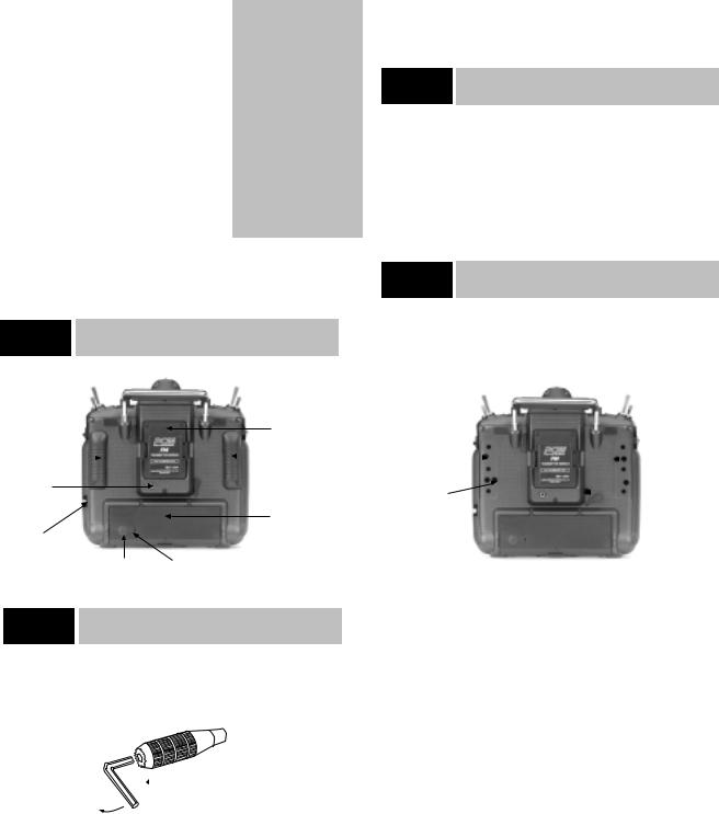
3 Transmitter Controls
Swiveling Antenna
AUX-5 Knob
Gear Switch
Flight Mode Switch
Low Pitch Trim Lever
Elevator Dual Rate Switch
Mix Switch
Hovering Pitch Knob
Throttle/Rudder Stick
Neck Strap Eyelet
Mechanical Throttle Trim
Digital Rudder Trim
On/Off Power Switch
Digital Elevator Trim
LCD Touch Panel Display
Tilting Antenna Base
Power Pilot Lamp
RF Output Lamp
Carrying Handle
AUX-4 Knob
Hovering Throttle Knob
 Aileron Dual Rate Switch
 High Pitch Trim Lever
Audible Speaker
 Aileron/Elevator Stick
Digital Aileron Trim
Antenna Storage
3.1Control Identification
Antenna
•The adjustable base can be locked into position by tightening the two screws just to the rear of the antenna ball mount. Do not over-tighten. This feature allows you to determine the antenna angle that suits you best and to lock it in place.
•The antenna can be removed and stored in the special compartment in the right side panel of the transmitter. The next time you fly, simply thread the antenna into the ball mount. It will automatically assume the previously set angle.
Note: Do not point your antenna directly at your model helicopter. The tip of the antenna is the weakest radio frequency radiator in any radio controlled transmitter. Instead, have the antenna at about a 20°– 45° angle away from the model.
For a proper range test of the PCM10X system please refer to Section 13, Daily Flight Checks.
10X MANUAL Heli |
7 |
Base Loaded Active Antenna
An optional base loaded active antenna is available for use with the PCM10X transmitter. It is considerably shorter than the standard antenna. However, the base loaded antenna cannot be collapsed for storage in the side of the transmitter. The base loaded antenna, part number JRPA155, is made of a flexible coil and is covered with a soft plastic material. Your range will not be affected when using the base loaded antenna.
Channel Assignment
1. |
THRO |
Throttle Channel |
|
2. |
AILE |
Aileron Channel |
|
3. |
ELEV |
Elevator Channel |
|
4. |
RUDD |
Rudder Channel |
|
5. |
GEAR |
Gear Channel |
|
6. |
AUX1 |
Auxiliary 1 (used for |
|
|
|
pitch w/collective pitch helis) |
|
7. |
AUX2 |
Auxiliary 2 |
Channel |
8. |
AUX3 |
Auxiliary 3 |
Channel or Code |
|
|
44 Gyro Gain (if active) |
|
9. |
AUX4 |
Auxiliary 4 |
Channel |
10. |
AUX5 |
Auxiliary 5 |
Channel |
11. |
BATT |
Receiver Battery Pack Port |
|
Throttle ALT
This function makes the throttle stick trim active only when the throttle stick is less than half throttle. This gives easy, accurate idle adjustments without affecting the high throttle position. In hovering flight, this feature will function as a simple high idle system.
3.2Transmitter Rear
A
Transmitter Module
Rubber Grip |
|
|
|
Rubber Grip |
|
|
|
DSC Jack
Battery Door
Antenna
Storage
Compartment
Battery Charging Jack Rubber Charge Jack Cover
3.3Stick Length Adjustment
Control Stick Length Adjustment
The PCM10X allows you to adjust the control sticks’ length.
 Loosen
Tighten
To adjust the stick length, use the 2mm Allen wrench (supplied with your PCM10X transmitter) to unlock the set screw.
Note: Turn the wrench counter clockwise to loosen the screw and clockwise to tighten it.
Turn the knurled part of the stick counterclockwise to lengthen and clockwise to shorten.
After the control stick length has been adjusted to suit your flying style, simply tighten the 2mm set screw.
If you desire longer sticks, JR has developed a new, thicker stick (JRPA047) which is approximately one inch longer than the standard sticks. This stick, crafted from bar stock aluminum, is available at your local JR dealer.
3.4Neck Strap Attachment
An eyelet is provided on the face of the PCM10X transmitter which enables you to connect a neck strap (JRPA023). This hook has been positioned so that your transmitter will have the best possible balance when you use a neck strap.
Cautionary Note: Please double check to ensure that the neck strap is securely fastened to the transmitter.
3.5Adjustment of Stick Tension
The 10X allows you to individually tailor the tension of each of your stick control inputs to suit your flying style. The procedure is as follows:
Elevator Tension |
|
Rudder Tension |
|||
Adjusting Screw |
|
|
|
||
|
|
|
|
|
Adjusting Screw |
Aileron Tension |
|
|
Throttle Tension |
||
|
|
||||
Adjusting Screw |
|
Adjusting Screw |
|||
1. Carefully remove the rear rubber grips. Do this by gently prying the grip by hand from the case.
2.Carefully remove the lower right-hand rubber plug. (The upper left rubber plug is used for adjusting Mode 1 transmitters only.)
3.Using a small Phillips screwdriver, rotate each adjusting screw clockwise to tighten its respective stick tension(counterclockwise to loosen).
After achieving the desired stick tension, carefully replace the rubber grips and plugs.
8 |
10X MANUAL Heli |
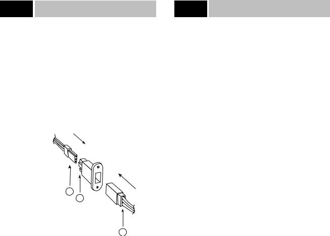
3.6Using the DSC Cord
Direct Servo Control (DSC)
For proper DSC hook-up and operation:
1.Leave the transmitter power switch in the “off” position. The transmitter will not transmit any radio frequency (RF) in this position.
2.Plug the DSC cord (supplied) into the DSC port in the rear of the transmitter.
3.The encoder section of the transmitter will now be operational and the LCD display will be lit.
4.Plug the other end of the DSC cord into the receiver charge receptacle. Turn the switch harness to the “on” position.
B
A
A - Charge Cord/DSC Receptacle |
|
B - Switch Harness Lead |
|
C - Charge Cord/DSC Receptacle |
C |
Note: When installing the switch hareness charging jack, be sure to hook the charging jack receptacle, JRPA024, securely into the switch harness charge cord.
Why you should use the DSC function:
1. The DSC enables you to check the control surfaces of your helicopter without drawing the fully operational 200ma from
your transmitter battery pack. Instead, you will only draw 70ma when using the DSC function.
2. The DSC function allows you to make final adjustments to your helicopter without transmitting any radio signals. Therefore, if another pilot is flying on your frequency, you can still adjust your helicopter and not interfere with the other pilot’s aircraft.
Note: Under no circumstances should you attempt to fly your helicopter with the DSC cord plugged in! This feature is for bench checking your helicopter only.
3.7Frequency Notes/Aircraft Only Frequencies
Frequency Notes
The PCM10X employs a plug-in module system for transmitter frequency changes. If you wish to change a frequency, you can simply change the radio frequency (RF) module, commonly referred to as either an RF module or transmitter module. The JR modules are universal for all of the modular frequency controlled systems. In other words, if you currently own a modular JR system, you can use the RF module from your current system with the new PCM10X.
The PCM10X can transmit in either pulse code modulation (PCM) or in pulse position modulation (PPM). Be certain to observe the following guidelines:
1.Do not operate your transmitter when another transmitter is using the same frequency, regardless of whether the second transmitter is PCM, PPM, AM or FM. You can never operate two transmitters on the same frequency simultaneously without causing interference to both receivers and crashing both aircraft.
2.For operation of your PCM10X with additional receivers, you should refer to the receiver compatibility chart. The chart is located in Section 8.25 of this manual.
Aircraft Only Frequencies
JR RF modules and receivers are available in 50, 53 and 72 MHz frequencies in the United States for use with model aircraft. Employing 72 MHz frequencies does not require a special operator’s license from the Federal Communications Commission (FCC). However, the 50 and 53 MHz frequencies require that you carry a Technician no code II license.
• A chart for all available frequencies is located in Section 14 of this manual.
10X MANUAL Heli |
9 |
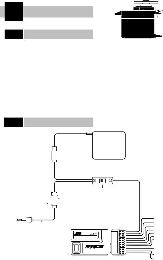
4 Connections
4.1Installation Requirements
It is extremely important that your radio system be correctly installed in your model. Here are a few suggestions on the installation of your JR equipment:
1.Wrap the receiver in protective foam rubber that is no less than 3/8 inch thick. Secure the foam to the receiver with #64 rubber bands. This will protect the receiver in a crash or a very hard landing.
2.The servos should be mounted using rubber grommets and brass bushings to isolate them from vibrations. Do not overtighten the mounting screws — this will negate the vibration absorption effect of the rubber grommets. The diagram at right will assist you in properly mounting your servo.
Servo Mounting Tab
Screw


 Rubber Grommet

 Brass Bushing
The brass bushings are pushed from the bottom up in the rubber grommets. When the servo screw is tightened securely, this will provide the proper security as well as the proper vibration isolation for your servo.
3.The servos must be able to move freely over their entire range of travel. Make sure that the control linkages do not bind or impede the movement of any of the servos.
4.Mount all switches away from the engine exhaust and away from any high vibration areas. Make sure the switch operates freely and is able to operate over its full travel.
5.Mount the receiver antenna firmly to the helicopter to ensure that it will not become entangled in the main and/or tail rotor blades of your helicopter.
4.2Connections
OFF |
ON |
Deluxe Switch Harness
JRPA001
Chargecord or
D.S.C. Receptacle
JRPA024
Chargecord or |
|
|
|
D.S.C. |
|
|
|
D.S.C. – JRPA123 |
|
|
BATT |
Chgr. – JRPC222 |
|
|
AUX 5 |
|
PROTECTION SYSTEM |
AUX 4 |
|
|
|
ABC&W INTERFERENCE |
|
|
|
|
AUX 3 |
|
|
|
AUX 2 |
|
|
|
AUX 1 |
RxFM |
D72.550 |
|
GEAR |
|
RUDD |
||
|
|
10 CH S-CLASS PCM RECEIVER |
ELEV |
|
|
JAPAN REMOTE CONTROL CO., LTD |
AILE |
|
|
THRO |
|
|
|
MADE IN JAPAN |
NER-950S
S-PCM Receiver
 Receiver Battery
1400mAh Sanyo Extra NiCad
JRPB4340
Auxiliary 5
Auxiliary 4
Auxiliary 3/Gyro Gain
Auxiliary 2
Auxiliary 1/Pitch
Gear
Rudder
Elevator
Aileron
Throttle
10 |
10X MANUAL Heli |
5 Display and Touch Panel
5.1Care of the Touch Screen
Avoid dust, moisture and extreme temperature changes.
Do not press on the display panel with sharp objects such as ball point pens.
Clean the screen with a soft, dry cloth only. Never use solvents of any kind to clean the display face.
The intensity of the screen will change with extreme temperature changes. This is normal and does not indicate a malfunction of your PCM10X. The screen will return to normal once the temperature has stabilized.
5.2Operating the Touch Panel
Basic operation of the panel is very simple. Just touch the key portion displayed on the LCD screen.
When you press any key, a beeping sound will confirm your input.
The + and - keys have an automatic repeat function. To activate, simply keep your finger on the key.
Note: The PCM10X has a new two-speed scroll function. By depressing the + or - key one touch at a time, you can make minute changes to the LCD display values. However, by keeping your finger on the + or - keys, the values will begin to change quite rapidly.
When + CL - is displayed on the LCD display, press the + and - keys simultaneously or the CL. The respective function value will clear back to the factory preset or default position.
Setting Percentage Display
and Key Input
When setting percentages, the digital display will only read in the range of useful operation and will stop changes when the end of a range is reached, even though the beeping sound may still be heard.
6 Alarm and Error Display
6.1Battery Alarm
When the transmitter voltage drops below 9.0 volts DC, the display will flash the word BATTERY and an audible alarm will sound. The audible alarm will sound 4 times consecutively, pause for a moment, then sound again, for a total of 24 times.
Notes pertaining to the battery alarm:
1. BATTERY will only flash if you are in the initial display screen. If you are in any other screen, you will only hear the beeping of the alarm. If you are flying when you hear this alarm, you should land immediately.
Battery will flash
2. You will be unable to access Code 84, Model Select, Code 28, Data Reset, Code 86, Data Transfer, when the battery alarm has sounded.
10X MANUAL Heli |
11 |

6.2Back Up Error Alarm
A five year lithium battery protects all pre-programmed data against main transmitter battery failure. The lithium battery also allows the 10X to retain all pre-programmed data in the event the transmitter battery pack is removed from the transmitter. Should the lithium battery fail, the display will indicate BACK UP ERR. and an audible alarm will sound. If this occurs, you will have to have the lithium battery replaced. All transmitter programs will return to the factory default settings, and the data you have entered will be lost and have to be re-programmed. When it becomes necessary to replace the lithium back-up battery, please contact Horizon Service Center. Improper removal or replacement can cause extensive damage, and only the Horizon Service Center is authorized to make this battery change.
Note: If you are flying when the lithium back-up battery fails, you will not lose control of your aircraft. However, when the transmitter power is turned off, all the programmed data will be lost. It is for this reason that we urge you to record all input data on the data sheet provided at the back of this manual.
6.3Switch Position Warning Message
If any switches are on that could be dangerous (e.g., Throttle Hold, Flight Mode-Stunt modes 1–4) when you first power up your transmitter, an audible alarm will sound. The display shows you which switches are out of position by flashing the name of the activated switch as shown below.
Flashing
Flashing
When the switches have been returned to their normal or “off” position, the screen changes to the standard display, and the audible alarm will cease to sound.
As a precautionary measure, we recommend that prior to starting your model you turn your radio “off” and then return it to the “on” position. If any of the critical switches are on without your knowledge, the transmitter will tell you.
6.4All Servo Hold Function: Main Screen
Your new PCM10X system is equipped with the new All Servo Hold function, located to the lower right side of the main screen.
This feature allows you to “hold” the movement of all servos so that the flight mode switch can be utilized to display trim values for each of the flight modes, all while your heli’s engine is still running.
This feature is very helpful because it allows the user to view the individual flight mode trim values on the main screen without having to turn off the helicopter’s engine.
The All Servo Hold function also has a special safety feature that will not allow the servos to be re-activated until the throttle stick is at the low position and the flight mode switch is in the low position. A warning will be displayed on the main screen instructing you to move the throttle stick and flight mode switch to the correct positions (FM Normal and Low Throttle).
Touch  to stop all servo movement
12 |
10X MANUAL Heli |
7 Data Input
There are two methods you can use to enter data in your PCM10X transmitter — code number access and direct mode method. Both methods work equally well, although the direct mode method may be easier to use until you become familiar with the code numbers on the PCM10X.
Turn the PCM10X power switch to the “on” position. The initial LCD screen will appear as follows:
Touch enter to advance to the next screen. The screen will then change to the following:
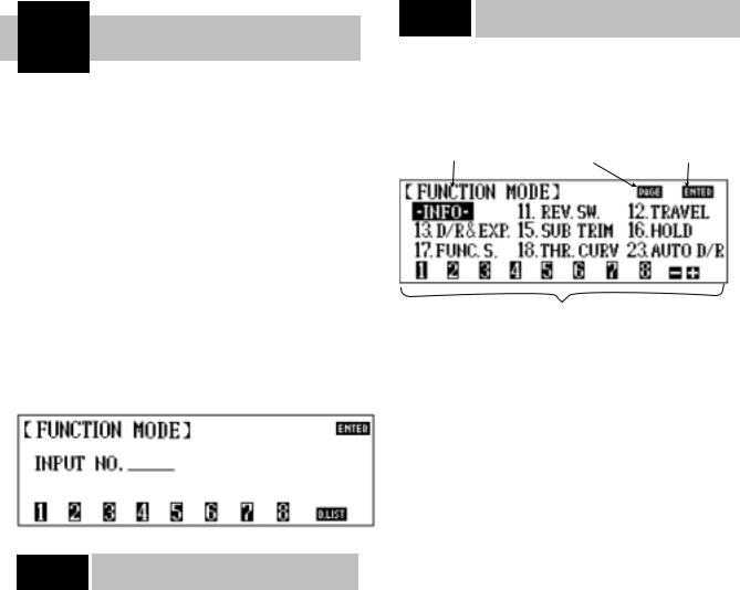
7.1Code Number Access
From this screen, you can input data with either method — code number access or direct mode method.
From the second screen, press the code number of the function you want to access. For example, if you desire to set the servo reversing switches, look up the corresponding code number on the chart located in Section 8 of this manual, in this case Code 11. Press 11 and the LCD display will show Reverse SW. Next, press enter and the display will change to show the reverse function.
After you have completed all of your set-ups for the desired code number, press enter and the screen will return to the function mode screen. Press ENTER again to return to the initial display screen.
7.2Direct Mode
If at screen 2 you are unsure of which code number to enter at this time, simply push the D.LIST key. This calls up the first nine
(9) functions (numerically) on the LCD display. This screen will display:
Shaded box indicates the |
Touch |
to advance |
Touch |
to enter |
function selected |
to next function screen |
the highlighted function |
||
Touch the code # then  to access the desired function or use the
  or
or  to shade the desired function and then press
If the code you want to access appears on this screen, push the + key until the shaded box (now highlighting the INFO function) highlights the chosen function. Next, press the ENTER key to enter the function. After making the necessary adjustments, press the ENTER key once again. This will bring you back to screen number 2. If at this point you touch the D.LIST key, the shaded box will return to the position you were at just prior to entering the desired code.
There are two ways to proceed to the next page of function selections:
1.Press the + key, advancing the highlighted box until the screen changes. This will occur if you press the + key one more time after reaching the last function on the selection screen.
2.Alternatively, press the PAGE key at any time to advance to the next selections.
Note: When changing screens in this manner, whichever function position is highlighted on the previous screen will continue to be highlighted. In other words, if the top right function is highlighted on page 1, when the PAGE key is pushed, the top right function will be highlighted on page 2.
10X MANUAL Heli |
13 |

8 Code Function
At the beginning of each code function in this manual, there is a brief explanation of the code and its significance to your helicopter. It’s important that you comprehend each code completely prior to moving on to the next code.
Code # |
Display |
Program Description |
11 |
Reverse SW |
Servo reversing switches—all channels |
12 |
Travel adjust |
Endpoint-travel adj.—all channels |
13 |
D/R & EXP |
Dual Rate & Exponential adjustment— |
|
|
Elev./Aileron/Rudder |
15 |
Sub-Trim |
Electronic means of centering all channels |
16 |
Throttle Hold |
Throttle hold position adjustments and throttle |
|
|
hold delay settings |
17 |
Function Select |
Selection of flight modes 3 and 4, gear, |
|
|
Aux 2, low pitch, and high pitch switches |
|
|
and levers, as well as Digital Trim inhibit |
|
|
function |
18 |
Throttle Curve |
Throttle curve settings |
23 |
Auto Dual Rate |
Automatic dual rate selection and adjustments |
28 |
Data Reset |
Individual program erasure and reset |
41 |
Rudder Throt Mix |
Adjusts throttle when rudder is applied |
42 |
Aileron Throt Mix |
Adjusts throttle when aileron is applied |
43 |
Elevator Throt Mix |
Adjusts throttle when elevator is applied |
44 |
Gyro Sens Adj. |
Gyro sensitivity adjustments; |
|
|
three available rates |
47 |
Tail Curve |
Revolution mixing selection and adjustment |
|
|
with multi-point tail curves for stunt |
|
|
modes 1–4 |
51-54 |
Standard Prog. Mix |
Program mixing selection and adjustments |
55-58 |
Multi-Point Prog. Mix |
Up to 6 point programmable curve |
65 |
Swash Mixing/Type |
Swashplate mixing selection and adjustments; |
|
|
independent swashplate timing adjustments |
|
|
available for both aileron and elevator. CCPM |
|
|
mixing 120° and 140° 3 servo is also avaliable |
68 |
Pitch Curve |
Pitch curve selection and adjustments |
75 |
Servo Monitor |
Servo monitor gives visual indication of all |
|
|
servo positions plus Servo Test—Slow & Step |
77 |
Fail-Safe |
Fail-safe memory & settings |
81 |
Model Name |
Model name memory input |
82 |
Trim Offset |
Trim offset correction adjustments |
83 |
Trim Rate |
Trim travel authority selection & adjustments |
|
|
from 100–0% in 1% increments |
84 |
Model Select/Copy |
Model Memory selections (1–10), Copy |
|
|
Function |
85 |
Modulation |
Modulation Selection (SPCM, ZPCM, PPM) |
86 |
Data Transfer |
Model memory transfer to/from another |
|
|
PCM10X or DataSafe |
87 |
Timer |
Countdown timer & Tx on time reset |
88 |
Keyboard Lock |
Keyboard lock password selection |
14 |
10X MANUAL Heli |

8.1Code 11
Reversing Switches
This is an electronic means of reversing the throw of a given (servo) channel. All ten (10) channels of the PCM10X offer reversible servo direction. This will ease setup during the servo installation into your helicopter.
Accessing and Utilizing the Servo
Reversing Feature
Prior to accessing the servo reversing feature, determine which servos’ travel needs to be reversed. To do so, move the controls of your PCM10X and observe the travel direction of each servo. If the respective servo is not moving properly, i.e., not in accordance with the control input, then reverse its direction.
Upon determining which channels need to be reversed, access the servo reversing feature by entering Code 11 in the code number access selection or by using the direct mode method.
Indicates which code is |
Depiction of servo |
Touch |
to |
being programmed |
travel direction |
memorize data and |
|
|
|
exit program |
|
Denotes travel direction (NOTE: If upper area is shaded, travel is reversed; If lower area is shaded, then travel is normal
Respective channel  number. Touch to reverse servo travel direction
The screen will appear as follows:
To reverse the travel direction of any servo (channel), simply touch the number which correlates to that channel. Note that the shaded portion of the upper box moves to the opposite position. This indicates the travel has been reversed.
Upon completing the servo’s travel direction, press ENTER to exit this feature and memorize the servo travel direction.
Note: All servo directions are set to their normal throw at the factory and are set at the default positions (Code 28 or clear).
10X MANUAL Heli |
15 |

8.2Code 12
Travel Adjust/ATV/End Point Adjust
The purpose of Travel Adjust, also known as adjustable travel volume (ATV) or end point adjust, is to allow you to adjust the total travel of a servo in both directions. The 10X offers travel adjust for all ten (10) channels. The travel adjustment range is from 0% to 150% and can be adjusted for each direction individually. Use this function to set the maximum control throws that you’ll use to fly the helicopter. However, make sure that servo travel is not so great that it causes binding by trying to move the surface past its physical limitations. A servo that is stalled causes high current drain and can cause radio drop outs, a condition where receiver voltage drops below its operational minimum, causing intermittent loss of control. A strong servo may also damage control surfaces and linkages if it travels too far.
Accessing and Utilizing the Travel Adjust/ATV
Feature
To access the Travel Adjust feature, enter Code 12 in the code number access selection or use the direct mode method.
The screen will appear as follows:
|
Touch to allow each |
Touch |
to |
Touch |
to |
Channel |
direction of travel adjust |
access the next |
memorize data and |
||
(servo) |
to be set individually |
five channels |
exit program |
|
|
Press the + key to increase the amount of servo travel and the - key to shorten the amount of servo throw. If you want to reset
the travel throw to the factory default, 100%, you can either press the + and - keys simultaneously or press the CL key.
After adjusting the travel volume for all ten (10) channels, press the ENTER key to exit this function and memorize these values.
Note: Any time you exit the Travel Adjust screen, the Travel
Adjust function will revert back to the simultaneous adjustment mode.
Touch |
to |
Touch |
to |
increase travel |
decrease the |
||
adjust for shaded |
travel adjust for |
||
area (0-150%) |
the shaded area |
||
|
|
(0-150%) |
|
Touch  simultaneously, or press CL to reset the shaded area to 100% factory default
The 10X has a new feature that makes setting up travel adjust both quicker and easier. The 10X allows the option of both travel adjustment directions (up/down, right/left) to be adjusted either simultaneously or independently. From the factory default settings, the 10X is set to simultaneously adjust both directions indicated by the shaded area. An S appears in the shaded box at the top of the screen (see above screen). This is helpful in adjusting the overall rough travel values of the servos. To independently fine tune travel adjustment in each direction, press the S button at the top of the screen. The shaded area now only covers one of the values and only that value will be adjusted.
Note: In this mode the shaded box follows the directional movement of the control. It is this value you will be adjusting.
16 |
10X MANUAL Heli |

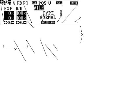
8.3Code 13
Dual Rate/Exponential Adjustments
Up to five programmable rates, each with their own exponential values, are offered on the aileron, elevator and rudder channels when flight modes are activated. (Three rates are available for aileron elevator and rudder in normal mode.) In addition, rate and expo values are independently adjustable in each direction, allowing you to perfectly tailor the response and feel of your helicopter. We’ve found this especially beneficial for aerobatics as the dual rate and expo values to achieve the same response/ feel with up and down elevator can be quite different.
Dual rates offer the ability to adjust the travel of the primary control surfaces (aileron, elevator, rudder) via a switch, thus altering the aircraft’s response rate so specific maneuvers can be achieved. Aggressive maneuvers like 3D aerobatics require large control throws, while slow rolls, rolling circles, etc., require much smaller control throws to avoid over-sensitivity. Dual rates allow you to change your aircraft’s response in flight.
Exponential does not affect the overall travel (end points) of the channel/servo. Exponential affects the rate at which the servo moves in intermediate positions (less than full travel) and is typically used to desensitize the neutral area such that minor corrections can be input easily to level the helicopter. When exponential is not used, the servo response rate is linear. That is, for every incremental step the control stick moves, the servo also moves in the same increments. If the stick moves 10%, the servo moves 10%.
When Exponential is activated, a positive (+) Expo value causes the servo to move less than the stick when the stick is near the neutral position. For example, the stick may be moved 20% while the servo moves 10%. As the stick is moved further from center, the servo movement is increased, and at the extremes of travel, the % of servo travel is actually higher than the stick travel. The larger the (+) Expo value selected, the less sensitivity (reduced servo movement) will occur around neutral, but a greater sensitivity will occur at the extremes of travel.
As mentioned, Expo is typically used to reduce sensitivity around neutral stick positions while still having high control authority at the extremes of travel. This provides the pilot with
very smooth, precise control while using relatively large movements with the control sticks. If you’d like to try Expo for the first time, a value of +20% is a good place to start. This will give you the feel that Expo offers, but won’t be so different than what you’ve been flying.
Note: The 10X allows a negative (-) Exponential value to be programmed. This has the opposite effect as described above in that (-) Expo values will cause the control response to be greater (more sensitive) around neutral. Negative Expo values are very seldom used and should be tried with caution.
Your 10X offers you your choice of five different response curves for your aileron, elevator and rudder controls. We suggest that you experiment with the curves, as they can greatly enhance the performance of your R/C aircraft.
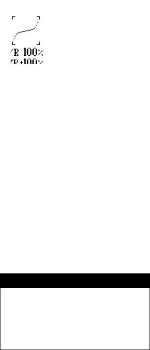
The graphs below are shown to help demonstrate how each of the response curves differ:
Graph 1 represents the normal, or linear, stick control. The servo response is equal throughout the stick movement.
Graph 2 represents the normal stick control with the introduction of positive exponential. The response or rate of servo travel is less at the neutral point and increases as the stick reaches its travel limits. This type of exponential rate is useful if the controls are very sensitive around the neutral point.
Note: If negative exponential were used, the response, or
“feel,” of the control would be opposite. The response, or rate, of servo travel would be greater near the neutral point.
Graph 3 represents the VTR (Variable Trace Rates). With the VTR feature activated, your transmitter operates in the dual rate mode until it reaches the selected VTR point (50%–90%). Control then switches to the higher rate.
Graph 4 represents a combination of linear and exponential rates. Your control functions on a linear curve until it reaches 50% stick travel, where it switches to an exponential curve. In other words, it is a linear center and a expo curved a the extremes of travel.
Graph 5 represents an Expo Linear curve. However, travel rates are exponential around center and then switch to linear after 50% of stick travel.
Graph 1 |
Graph 2 |
Graph 3 |
Graph 4 |
Graph 5 |
10X MANUAL Heli |
17 |
Accessing and Utilizing the
Dual Rate/Exponential Feature
To access the Dual Rate and Exponential features, enter Code 13 in the code number access selection or use the direct mode method.
Your screen will appear as follows:
Indicates feature |
Touch |
to select |
being accessed |
D/R switch position |
|
Indicates channel |
|
Indicates D/R switch |
relative to D/R |
|
position for respective |
exponential |
|
channel |
adjustments |
|
|
Touch |
to |
Dual rate value |
alter dual rates/ |
|
|
exponential values for |
Type of |
|
channel and switch |
exponential |
|
position indicated |
|
Exponential value D/R curve |
Touch  to select next channel
Touch  to memorize
data and exit program
Graphic dual rate and exponential curve
Touch  to clear D/R/exponential curve and return to normal
Touch  to select type of D/R/exponential curve
Note: Although dual rates and exponential operate in conjunction with one another, we will cover them separately.
Dual Rates
The adjustable range for each of the dual rate positions is 0-100%.
In normal flight mode, the dual rates used are dependent on the 0 and 1 switch position for each of the applicable channels. When the stunt modes and the throttle hold switches are activated, the rates are controlled by the auto dual rate function,
Code 23, located in Section 8.8 of this manual.
First, touch the PAGE key to call up the desired channel (aileron, elevator, or rudder) for which you want to adjust the rate.
Select the switch position for which you want to adjust the rate. Keep in mind that 0 and 1 pertain to the D/R switches when in the normal flight mode, while the 2 position may be called up on the auto dual rate feature.
Next, adjust the rate for the channel and the switch position that you have previously selected. To decrease the throw rates, touch the - key. To increase the throw rate, touch the + key.
Note: It is not possible to increase the throw rate from the factory default settings. You may observe the servo changes by moving the respective stick while increasing or decreasing the values. The control changes accordingly. To clear the dual rate, touch the CL key, or the + and - keys simultaneously.
After the rates have been dialed in to your satisfaction, begin to adjust the exponential values. Remember that the exponential values do not change the rates. They only alter the way in which this travel is reached.
Adjustment of the Exponential Curves
The adjustable range of the exponential curve is ±100% for each of the positions and the respective channels.
The greater the positive exponential value, the less servo action or sensitivity you will notice around the neutral setting. The opposite is also true: The greater the negative value, the more servo action or sensitivity you will notice at the neutral point.
The following graphs may aid in understanding the exponential curve.
The response or rate of servo travel is less at the neutral point and increases as the stick reaches its travel limits. This type of exponential rate is useful if the controls are very sensitive around the neutral point.
The response rate of this servo is more around neutral and decreases as the stick reaches its travel limits. This type of exponential rate is useful if the control is very slow or unresponsive around the neutral point.
To adjust the exponential rate use the +, - and CL keys. The + key increases the exponential rate, while the - key decreases the response rate. To clear the exponential rate, touch the CL key, or the + and - keys simultaneously.
VTR: Variable Trace Rate
This feature may be thought of as a double dual rate. The adjustable range of VTR is from 50-90% in 10% increments.
When VTR is active, the servo response remains linear over the first portion of the dual rate curve and then switches to the higher rate at the point you have selected.
To select among the VTR rates, touch the SEL on the lower portion of the LCD screen.
As you can see in the graphs at the bottom of the page, over the first portion of travel the servo response rate is linear, but at the variable trace rate, it switches to the higher rate of travel.
18 |
10X MANUAL Heli |
You also have the choice of either an exponential/linear curve or linear/exponential. These curves appear as follows:
Up to 50% stick travel around center at the linear rate, it then switches to exponential. In other words, it operates both ways, linear over the first portion of the curve and with an exponential rate over the last portion.
Up to 50% stick travel around center at the exponential rate, it then switches to the linear rates. In other words, it operates both ways: exponentially over the first portion of the curve and with a linear rate over the last portion.
Summary of Exponential Curve Selections
Normal |
Linear, D/R or Exponential Adjustments |
|
|
VTR 50% |
Will operate in dual rate mode until it |
|
reaches the selected VTR point; control |
VTR 90% |
will then switch to the higher rate |
|
|
EXP/LIN |
Up to 50% stick travel around center at pre- |
|
set exponential value and switch to linear |
|
|
LIN/EXP |
Up to 50% stick travel around center at pre- |
|
set linear value and switch to exponential |
|
|
Set Up Tip
Exponential
Many fliers have found that using exponential on fore/aft and right/left cyclic allows them to input more precisely minor corrections during hovering, while still allowing adequate control throw at the end of the stick travel. We recommend +15% expo on ailerons and elevator as a good starting point.
Adjusting Dual Rates and Expo Value Independently
in Each Direction
The 10X allows dual rates and/or Expo values to be independently adjusted in each direction of servo travel. This is extremely useful in that many aircraft have differing pitch, roll or yaw rates in each direction, and a different value is needed to achieve the
same response and feel in both directions. It’s typical for an aerobatic aircraft to require slightly more down dual rate and less Expo value to achieve the same feel for up and down elevator.
To independently adjust the dual rate or Expo value for each direction, simply move the appropriate stick in the desired direction, and the shaded box will highlight only the selected direction. Now adjustments can be made to that direction only.
10X MANUAL Heli |
19 |
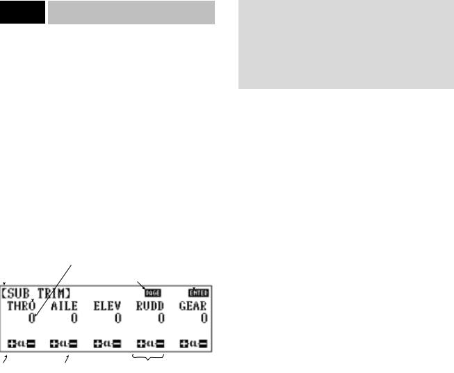
8.4Code 15
Sub-Trim Adjustment
The sub-trim adjustment is a feature that allows you to electronically fine-tune the centering of your servos. Individually adjustable for all ten (10) channels with a range of +/-250% in increments of 2% (+/-30° servo travel), the sub-trims can be set for the same neutral settings for each model stored in the transmitter’s memory. This allows the same mechanical trim tab settings between all of the models you control with the same transmitter. You don’t have to make the precise mechanical adjustments to your aircraft to achieve these results, as you would normally have to do with a standard transmitter.
Accessing and Utilizing the Sub-Trim
Adjustments
To access the sub-trim adjustments, enter Code 15 in the code number access selection or use the direct mode method.
The screen will appear as follows:
Indicates which code |
|
|
|
|
|
||
is being programed |
Offset value ± |
|
Touch |
to |
|||
|
|
|
|
||||
|
Channel (servo) |
Touch |
to display |
memorize data |
|
||
|
|
|
other five channels |
and exit program |
|||
|
|
|
|||||
|
|
|
|
|
|
|
|
|
|
|
|
|
|
|
|
Note: On previous generation of JR’s 10-channel computer radios, the sub-trim adjustment values are adjustable from 0 to
125% in 1% increments. Your 10X in adjustable in 2% increments up to 250%. If you’re transferring over sub-trim values from a previous generation JR 10-channel radio to the 10X, the sub-trim values of the older 10-channel radio must be doubled in order to properly match when programmed into the 10X.
Touch |
to |
Touch |
to |
increase |
|
decrease |
|
trim value |
|
trim value |
|
Touch  and
and  simultaneously, or press CL to reset to factory default setting, 0
This feature enables you to electronically correct for slight mechanical misalignments that previously had to be corrected manually.
Caution: Do not use excessive sub-trim adjustments since it is possible to overrun your servo’s maximum travel if it is offcenter. Remember that this is a trim convenience feature. It is not intended to take the place of the proper mechanical trim adjustments that are necessary on any R/C model. Offset servos also produce a differential throw effect.
For corrections in trim offsets of aileron, elevator, and rudder channels, refer to Code 82, trim offset adjustment.
Press the + key to increase the amount of offset or press the - key to decrease (actually increase) the amount of opposite offset. To reset the sub-trims to the factory default, 0, press the + and - keys simultaneously or press the CL key.
After adjusting the sub-trims for the first five channels, touch the PAGE key to access the last five channels.
Upon completion of the sub-trim adjustments, press the ENTER key to memorize the settings and to exit the program.
20 |
10X MANUAL Heli |
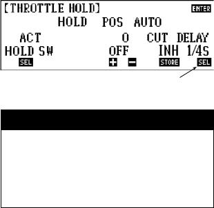
8.5Code 16
Throttle Hold
The Throttle Hold function (when activated) allows you to retain control of the collective servo, yet leave the throttle servo at a pre-determined position. This feature is particularly useful for autorotations. It switches the throttle servo to a preset position and disconnects it from the control stick, but leaves the collective pitch control with the stick position.
Accessing and Utilizing
the Throttle Hold Function
To access the Throttle Hold function, enter Code 16 in the code number access selection or use the direct mode method. The screen will appear as follows:
Indicates which code |
Touch |
to |
is being programmed |
exit program |
|
Touch |
to activate |
Shows that throttle |
the throttle hold program |
hold is inhibited |
|
Touch the ACT key to activate the throttle hold feature. The screen will now appear as follows:
If the switch is active (as in the example) and the switch is in the "OFF" position, "OFF" will appear below the throttle hold position
If the switch has been activated and is in the "ON" position, the "OFF" indication will not appear
Indicates which feature |
Touch |
to store/clear |
Touch |
to memorize |
is being programmed |
auto cut (throttle) position |
data and exit program |
||
Touch |
Touch the |
or |
keys to |
Touch |
to activate |
to activate the |
increase/decrease, respectively, the |
the throttle hold delay |
|||
gear switch for |
value (position) that the throttle servo |
function and select the |
|||
throttle hold |
will assume when it is put into the |
desired delay value: |
|||
|
throttle hold position |
|
1/4 second |
3/4 second |
|
|
|
|
|
1/2 second |
1 second |
If the switch is active (as in the example) and the switch is in the “off” position, “off” will appear below the throttle hold position. If the switch has been activated and is in the “on” position, the “off” indication will not appear.
If the program is returned to the inhibited selection, the values are retained (for the hold position and automatic throttle cut options) for the next time Throttle Hold, Code 16, is accessed within the same model.
Touch the + or - keys to increase/decrease, respectively, the value (position) that the throttle servo will assume when it is put into the throttle hold position.
Hold Position
The adjustable value for the throttle hold position is between 0 to 100 and is pro-rated to the throttle curve value.
The value (position) you program for the hold position is the position which your throttle servo assumes when the Hold function is activated.
The word “off” may appear below the hold position value if the throttle hold switch is in the “off” position or if the throttle stick has not been reduced below the automatic cut position.
Note: The high and low pitch trim levers, if activated in Code 17, Function Select, still affect the high and low pitch curve, even if the Throttle Hold function is activated.
Auto Cut Setting
The auto cut setting may be easier to think of as an automatic throttle cut-off point, since this is the function it performs. This feature allows you to select whatever throttle stick position activates the Throttle Hold function. Although the throttle hold switch may be active, the throttle servo itself also remains active, i.e., following the throttle stick movement, until you reach the auto cut position that you are about to select.
Selecting the Auto Cut Position
This process is a very simple one. Place the throttle stick to the position for which you desire the throttle hold to become active and touch the key located below the auto cut. The display now exhibits the value of the stick position that you have selected.
This value will be between 0–100%
If you want to change the auto cut point after you have already selected one, touch the CL key below the auto cut. This inhibits the previous position. Next, move the throttle stick to the desired location and press the STORE key. The new value will be displayed at this time.
Most model helicopter pilots select a point very near the lowest throttle stick position for their auto cut position.
Note: If you opt not to select a point for the auto cut to engage, the throttle servo immediately assumes its hold position once the throttle hold switch is activated.
10X MANUAL Heli |
21 |
Throttle Hold Delay
The Throttle Hold Delay function is a new addition to the PCM10X software. This feature functions as a way to delay or “Slow” the throttle servo’s movement when switching from throttle hold back to the previous flight mode.
This feature is very helpful when practicing autorotations as it allows the autorotation to be aborted if necessary, without the usual harsh return to full power. In conventional systems, when an autorotation is aborted, the engine immediately returns to an extremely high throttle position as indicated by the previous flight mode. This situation causes a very high load to be applied to the main gear and drive train of the helicopter due to the engine’s immediate return to power, and in some cases it can damage the main drive gear, or other components of the helicopter. This sudden return to power can also cause the helicopter to rotate violently due to the immediate return of torque, which can startle the pilot at the very least.
The Throttle Hold Delay function eliminates all of the previously mentioned problems by bringing the engine back to full power smoothly. This feature can be custom tailored to the individual pilot’s requirements and is adjustable in increments of 1/4 second,1/2 second,3/4 second, and 1 second delay times.
Press  to select the desired Throttle Hold Delay value: 1/4 second, 1/2 second, 3/4 second, 1 second
Set Up Tip
Establishing Your Throttle Hold Delay Value
For initial testing of the Throttle Hold Delay function in flight, it is suggested that you start at the 1/4 second setting for the first flight so you can develop the feel for this function. Increase the delay time as needed until the desired delay time is achieved.
22 |
10X MANUAL Heli |

8.6Code 17
Function Select
Function Select allows you to activate/inhibit flight modes 3 and 4 and assign the switch position, to assign the function of the gear switch (hold, gear, inhibit), to activate the function of the Aux2 switch and to activate/inhibit the low and high pitch trim levers. This function also allows the user to inhibit the Digital Trim function in Stunt Modes 1–4 if desired.
Accessing and Utilizing the
Function Select Function
To access the Function Select function, enter Code 17 in the code number access selection or use the direct mode method.
The screen will appear as follows:
Indicates Flight Mode 3 |
|
|
Press |
to |
and 4 status (INH or ACT) |
|
|
||
|
|
exit the function |
||
|
Press |
to |
||
Indicates which code is |
select mode and |
|||
being programmed |
access screen 2 |
store data |
|
|
Touch |
to |
Touch |
to |
Touch |
to |
Touch |
to inhibit |
activate Stunt Modes |
select gear switch |
activate AUX 2 |
the digital trim function |
||||
3 and 4 and assign |
function (GEAR, |
switch |
|
in Stunt Modes 1–4, |
|||
the designated |
HOLD, INH) |
|
|
|
and hold |
|
|
switch (AIL or GEAR)
|
Press |
to |
Press |
to |
|
return to the |
|
store data and exit |
|
Indicates which code is |
function select |
the function select |
||
being programmed |
screen #1 |
|
function |
|
Press the  key to activate the low and high pitch trim levers
Extra Flight Mode Function
(Flight Mode 3 and 4)
The Extra Flight Mode function allows two additional flight modes (3 and 4) to be activated and placed on the gear switch or the aileron dual rate switch.
Touch SEL located below the flight extra on the left-hand side of the screen once to activate the Flight Modes 3 and 4 on the gear switch (gear) and touch SEL again to activate Flight Modes 3 and 4 on the aileron dual rate switch.
Note: Flight Modes 3 and 4 work in conjunction with the flight modes N, 1, and 2 switch.
When the flight mode switch is in the Normal (N) position, Normal mode is selected regardless of the extra flight mode switch position. When the flight mode switch is in the #1 or #2 position, the actual flight mode is relative to the position of the extra flight mode switch. If the extra flight mode switch is on, the position 1 and 2 on the standard flight mode switch result in Flight Modes 3 and 4.
Separate throttle curves, pitch curves, stunt trims, tail curves, programmable mixes, swashplate timing, auto dual rates and gyro rates are available in Normal, Flight Mode 1, Flight Mode 2, Flight Mode 3 and Flight Mode 4. See these sections for details.
Gear Switch
Channel 5, gear switch, can be programmed in these different ways:
When the GEAR appears below GEAR SW on the screen, the gear two-position switch activates on Channel 5. Touch SEL and HOLD will appear. Now Channel 5 is activated with the throttle hold switch. Touch SEL again and INH (inhibit) appears. This inhibits Channel 5, and Channel 5 is now useful as a Slave channel for programmable mixing in this inhibit position.
AUX2 Switch
Channel 7, Auxilary 2, can be programmed in these different ways:
When ACT appears below AUX2 SW on the screen, the AUX2 switch on the transmitter activates the function of channel 7.
When INH appears on the screen, Channel 7 is now useful as a slave channel for programmable mixing in this inhibited position.
Digital Trim Select
The Digital Trim Select function located at the lower right corner of the screen, allows the user to deactivate the Digital Trim Levers in Stunt Modes 1–4 and Hold, while retaining the previously established trim values.
10X MANUAL Heli |
23 |
 Loading...