

Page 1

GC 2225
GC 2225C
Please read the operator’s manual carefully and make sure you understand the instructions before using the
machine.
Lesen Sie die Bedienungsanweisung sorgfältig durch und machen Sie sich mit dem Inhalt vertraut, bevor Sie das Gerät benutzen.
Lire attentivement et bien assimiler le manuel d’utilisation avant d’utiliser la machine.
Prima di usare la macchina, leggere per intero le istruzioni per l’uso e accertarsi di averne compreso il contenuto.
Lea detenidamente el manual de instrucciones y asegúrese de entender su contenido antes de utilizar la máquina.
Leia as instruções para o uso com toda a atenção e compreenda o seu conteúdo antes de fazer uso da máquina.
¢И·Я¿ЫЩВ ЪФЫВОЩИО¿ ЩИ˜ √‰ЛБ›В˜ ¯Ъ‹ЫВˆ˜ О·И О·Щ·УФ‹ЫЩВ ЩФ ВЪИВ¯fiМВУФ ЪИУ ¯ЪЛЫИМФФИ‹ЫВЩВ ЩФ МЛ¯¿УЛМ·.
Operator′s manual
Manuel d’utilisation
Bedienungsanweisung
Istruzioni per l’uso
Manual de instrucciones
Instruções para o uso
√‰ËÁ›Â˜ ¯Ú‹Ûˆ˜
GB (2-26)
FR (27-51)
DE (52-76)
IT (77-101)
ES (102-126)
PT (127-151)
GR (152-177)
Page 2
KEY TO SYMBOLS
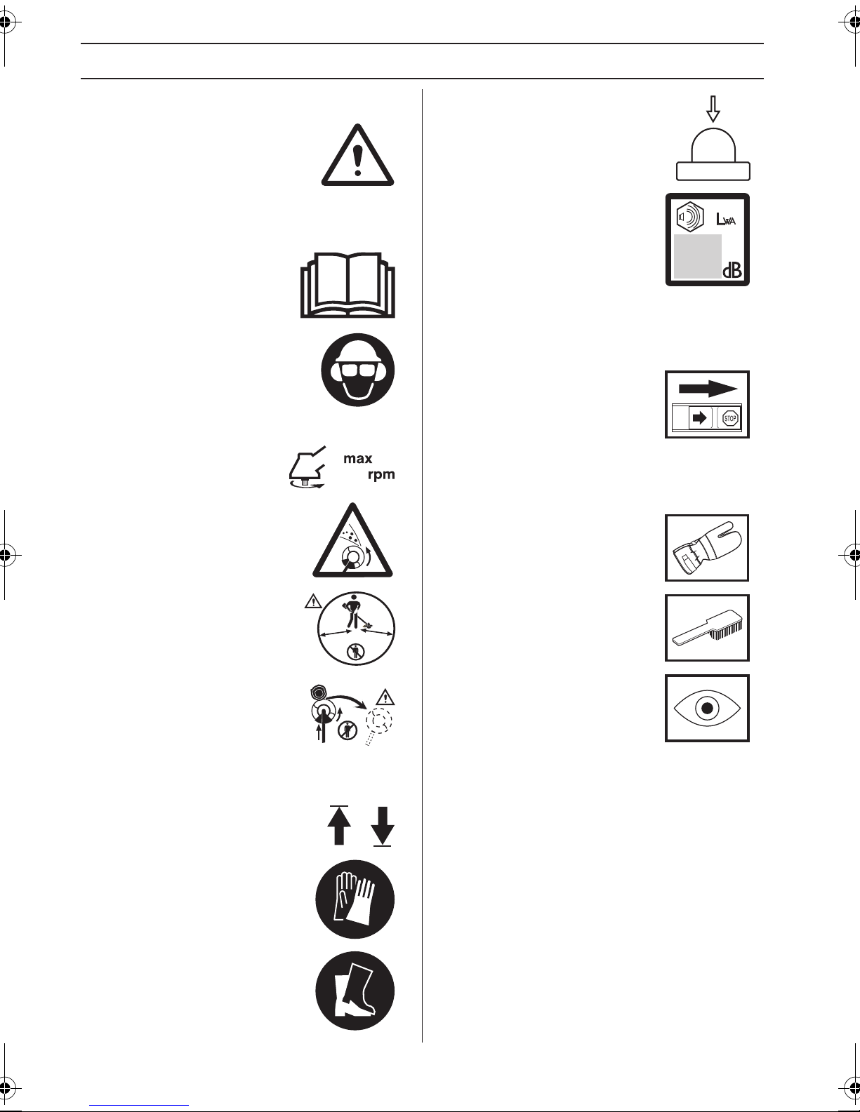
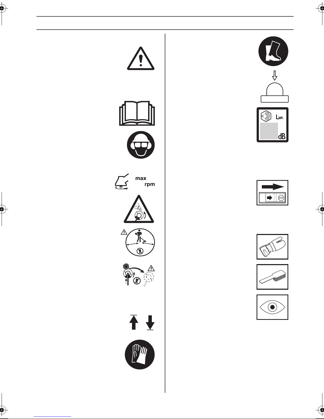
Symbols
WARNING! Clearing saws,
brushcutters and trimmers can be
dangerous! Careless or incorrect use
can result in serious or fatal injury to
the operator or others. It is extremely
important that you read and understand the contents of
the operator's manual.
Please read the operator’s manual
carefully and make sure you
understand the instructions before
using the machine.
Always wear:
• Wear a protective helmet where
there is a risk of falling objects
• Approved hearing protection
• Approved eye protection
Max. speed of output shaft, rpm
10000
Watch out for thrown objects and
ricochets.
Primer bulb
Noise emission to the environment
according to the European
Community’s Directive. The
machine’s emission is specified in
the Technical data chapter and on the
label.
Other symbols/decals on the machine refer to
special certification requirements for certain
markets.
The engine is switched off by moving
the stop switch to the stop position.
CAUTION! The stop switch
automatically returns to the start
position. In order to prevent
unintentional starting, the spark plug cap must be
removed from the spark plug when assembling, checking
and/or performing maintenance.
Always wear approved protective
gloves.
The operator of the machine must
ensure, while working, that no
persons or animals come closer
15 m
50FT
15
m
5
0
FT
than 15 meters.
Machines fitted with saw blades or
grass blades can be thrown violently
to the side when the blade comes
into contact with a fixed object. This is
called blade thrust. The blade is
capable of amputating an arm or leg. Always keep people
and animals at least 15 meters from the machine.
Arrows which show limits for handle
positioning.
Always wear approved protective
gloves.
Wear sturdy, non-slip boots.
Regular cleaning is required.
Visual check.
2 – English
Page 3
CONTENTS
Contents Note the following before
KEY TO SYMBOLS
Symbols ................................................................ 2
CONTENTS
Contents ............................................................... 3
Note the following before starting: ........................ 3
INTRODUCTION
Dear Customer, .................................................... 4
WHAT IS WHAT?
What is what? ....................................................... 5
GENERAL SAFETY PRECAUTIONS
Important .............................................................. 6
Personal protective equipment ............................. 6
Machine′s safety equipment ................................. 7
Cutting equipment ................................................ 9
ASSEMBLY
Fitting the loop handle .......................................... 11
Fitting the J-handle .............................................. 11
Fitting the suspension ring ................................... 11
Assembling the cutting equipment ....................... 11
Fitting the trimmer guard and trimmer head ......... 12
Assembling and dismantling the two-piece shaft . 12
Fitting a blade guard, grass blade and grass cutter 13
FUEL HANDLING
Fuel safety ............................................................ 14
Fuel ...................................................................... 14
Fueling .................................................................. 15
STARTING AND STOPPING
Check before starting ........................................... 16
Starting and stopping ........................................... 16
WORKING TECHNIQUES
General working instructions ................................ 18
MAINTENANCE
Carburettor ........................................................... 21
Cooling system ..................................................... 21
Spark plug ............................................................ 21
Two-piece shaft ................................................... 22
Air filter ................................................................. 22
Maintenance schedule ......................................... 23
TECHNICAL DATA
Technical data ...................................................... 24
EC Declaration of Conformity ............................... 26
starting:
Please read the operator's manual carefully.
WARNING! Long-term exposure to noise
!
!
!
can result in permanent hearing
impairment. So always use approved
hearing protection.
WARNING! Under no circumstances may
the design of the machine be modified
without the permission of the
manufacturer. Always use original
accessories. Non-authorized
modifications and/or accessories can
result in serious personal injury or the
death of the operator or others.
WARNING! A clearing saw, brushcutter
or trimmer can be dangerous if used
incorrectly or carelessly, and can cause
serious or fatal injury to the operator or
others. It is extremely important that you
read and understand the contents of this
operator’s manual.
English – 3
Page 4

INTRODUCTION
Dear Customer,
Congratulations on your choice to buy a Jonsered product!
We are convinced that you will appreciate with great satisfaction the quality and performance of our product for a very
long time to come. The purchase of one of our products gives you access to professional help with repairs and service
whenever this may be necessary. If the retailer who sells your machine is not one of our authorised dealers, ask for the
address of your nearest service workshop.
It is our wish that you will be satisfied with your product and that it will be your companion for a long time. Think of this
operator′s manual as a valuable document. By following its content (usage, service, maintenance, etc), the life span and
the second-hand value of the machine can be extended. If you sell this machine, make sure that the operator′s manual
is passed on to the buyer.
Good luck on using your Jonsered machine!
Jonsered has a policy of continuous product development and therefore reserves the right to modify the design and
appearance of products without prior notice.
4 – English
Page 5
WHAT IS WHAT?
10
17
18
24
25
19
4
3
2
1
4
23
26
8
6
29
5
28
27
31
21
11
9
7
30
13
14
16
12
15
20
22
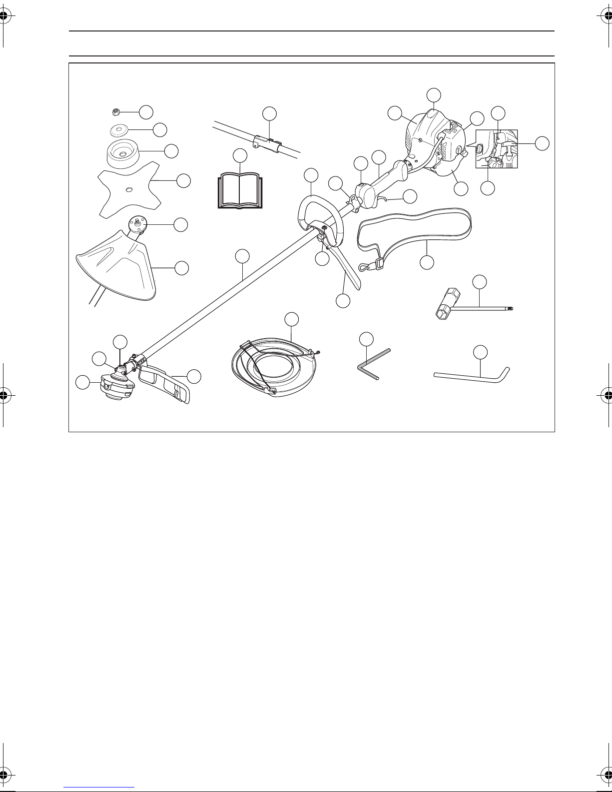
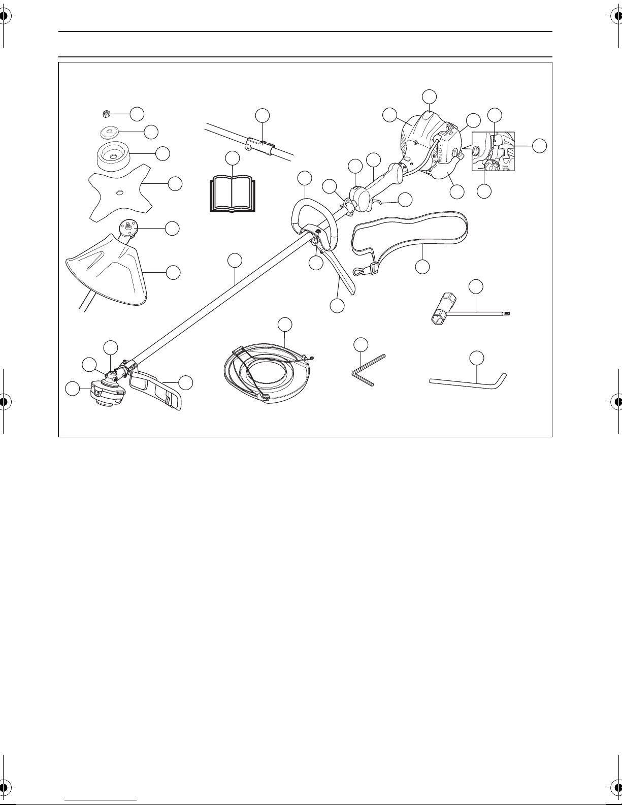
What is what?
1 Trimmer head
2 Grease filler cap, bevel gear
3 Bevel gear
4 Cutting attachment guard
5 Shaft
6 Loop handle
7 Throttle trigger
8 Stop switch
9 Throttle lockout
10 Spark plug cap and spark plug
11 Cylinder cover
12 Starter handle
13 Fuel tank
14 Air filter cover
15 Primer bulb
16 Choke control
17 Locking nut
18 Support flange
19 Drive disc
20 Combination spanner
21 Allen key
22 Locking pin
23 Operator′s manual
24 Support cup
25 Blade
26 Shaft coupling (GC2225C)
27 J-handle
28 Handle adjustment
29 Suspension ring
30 Harness
31 Transport guard
English – 5
Page 6
GENERAL SAFETY PRECAUTIONS
Important Personal protective equipment
IMPORTANT!
The machine is only designed for trimming grass.
National or local regulations may regulate the use.
Comply to given regulations.
The only accessories you can operate with this engine
unit are the cutting attachments we recommend in the
chapter on Technical data.
Never use the machine if you are tired, if you have drunk
alcohol, or if you are taking medication that could affect
your vision, your judgement or your co-ordination.
Wear personal protective equipment. See instructions
under the ”Personal protective equipment” heading.
Never use a machine that has been modified in any way
from its original specification.
Never use a machine that is faulty. Carry out the safety
checks, maintenance and service instructions described
in this manual. Some maintenance and service measures
must be carried out by trained and qualified specialists.
See instructions under the Maintenance heading.
All covers, guards and handles must be fitted before
starting. Ensure that the spark plug cap and ignition lead
are undamaged to avoid the risk of electric shock.
The machine operator must ensure that no people or
animals come closer than 15 metres while working. When
several operators are working in the same area the safety
distance should be at least 15 metres.
IMPORTANT!
A clearing saw, brushcutter or trimmer can be dangerous
if used incorrectly or carelessly, and can cause serious or
fatal injury to the operator or others. It is extremely
important that you read and understand the contents of
this operator’s manual.
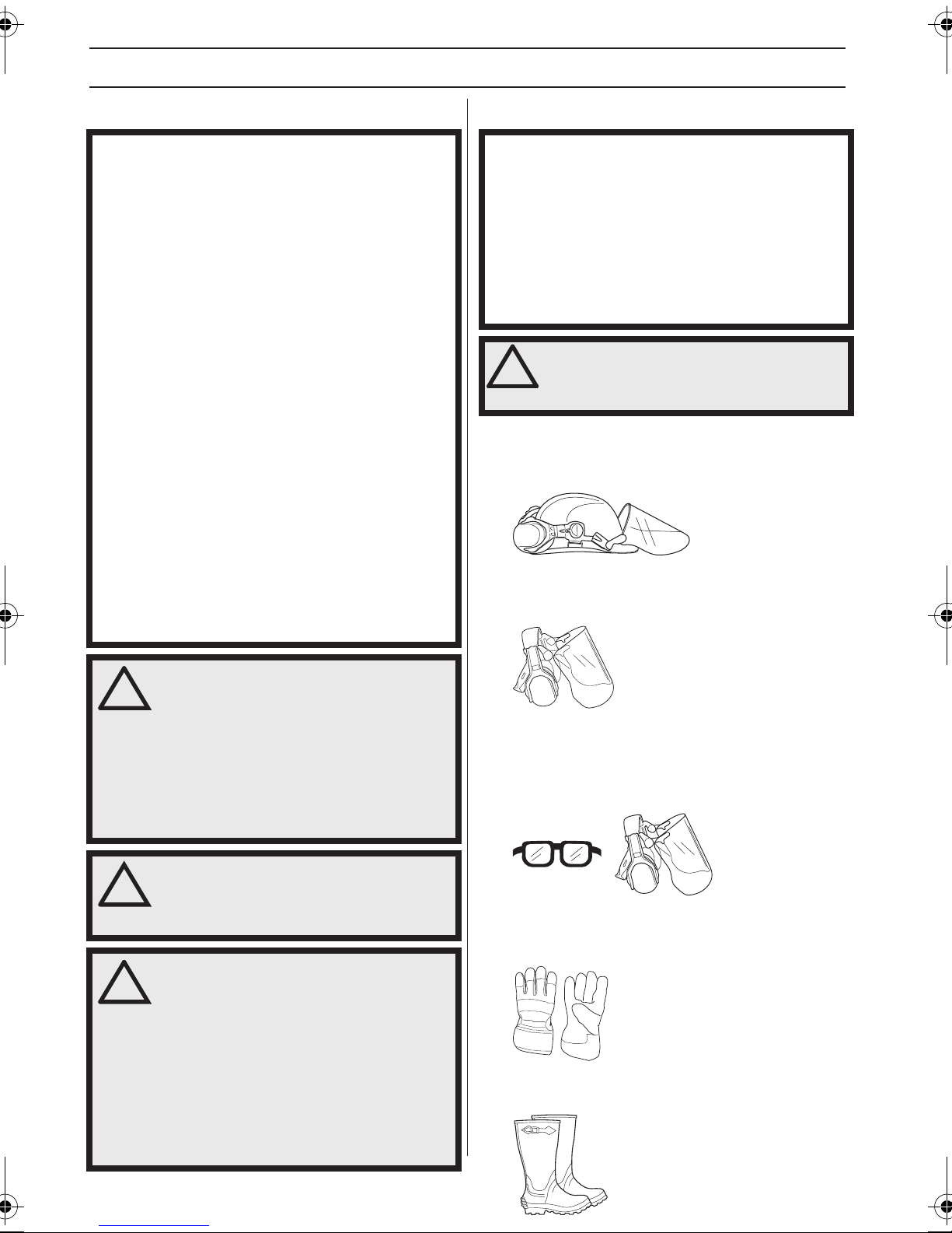
You must use approved personal protective equipment
whenever you use the machine. Personal protective
equipment cannot eliminate the risk of injury but it will
reduce the degree of injury if an accident does happen.
Ask your dealer for help in choosing the right equipment.
WARNING! Listen out for warning signals
!
HELMET
Wear a protective helmet where there is a risk of falling
objects
HEARING PROTECTION
Wear hearing protection that provides adequate noise
reduction.
or shouts when you are wearing hearing
protection. Always remove your hearing
protection as soon as the engine stops.
WARNING! This machine produces an
!
!
!
electromagnetic field during operation.
This field may under some
circumstances interfere with active or
passive medical implants. To reduce the
risk of serious or fatal injury, we
recommend persons with medical
implants to consult their physician and
the medical implant manufacturer before
operating this machine.
WARNING! Running an engine in a
confined or badly ventilated area can
result in death due to asphyxiation or
carbon monoxide poisoning.
WARNING! Never allow children to use or
be in the vicinity of the machine. As the
machine is equipped with a springloaded stop switch and can be started by
low speed and force on the starter
handle, even small children under some
circumstances can produce the force
necessary to start the machine. This can
mean a risk of serious personal injury.
Therefore remove the spark plug cap
when the machine is not under close
supervision.
EYE PROTECTION
Always wear approved eye protection. If you use a visor
then you must also wear approved protective goggles.
Approved protective goggles must comply with the ANSI
Z87.1 standard in the USA or EN 166 in EU countries.
GLOVES
Gloves should be worn when necessary, e.g. when fitting
cutting attachments.
BOOTS
Wear boots with steel toe-caps and non-slip sole.
6 – English
Page 7
GENERAL SAFETY PRECAUTIONS
CLOTHING
Wear clothes made of a strong fabric and avoid loose
clothing that can catch on twigs and branches. Always
wear heavy, long pants. Do not wear jewellery, shorts
sandals or go barefoot. Secure hair so it is above shoulder
level.
FIRST AID KIT
Always have a first aid kit nearby.
Machine′s safety equipment
This section describes the machine′s safety equipment,
its purpose, and how checks and maintenance should be
carried out to ensure that it operates correctly. See the
”What is what?” section to locate where this equipment is
positioned on your machine.
The life span of the machine can be reduced and the risk
of accidents can increase if machine maintenance is not
carried out correctly and if service and/or repairs are not
carried out professionally. If you need further information
please contact your nearest service workshop.
Make sure the throttle control is locked at the idle setting
when the throttle lockout is released.
Press the throttle lockout and make sure it returns to its
original position when you release it.
Check that the throttle trigger and throttle lockout move
freely and that the return springs work properly.
IMPORTANT!
All servicing and repair work on the machine requires
special training. This is especially true of the machine′s
safety equipment. If your machine fails any of the checks
described below you must contact your service agent.
When you buy any of our products we guarantee the
availability of professional repairs and service. If the
retailer who sells your machine is not a servicing dealer,
ask him for the address of your nearest service agent.
WARNING! Never use a machine with
!
faulty safety equipment. The machine's
safety equipment must be checked and
maintained as described in this section. If
your machine fails any of these checks
contact your service agent to get it
repaired.
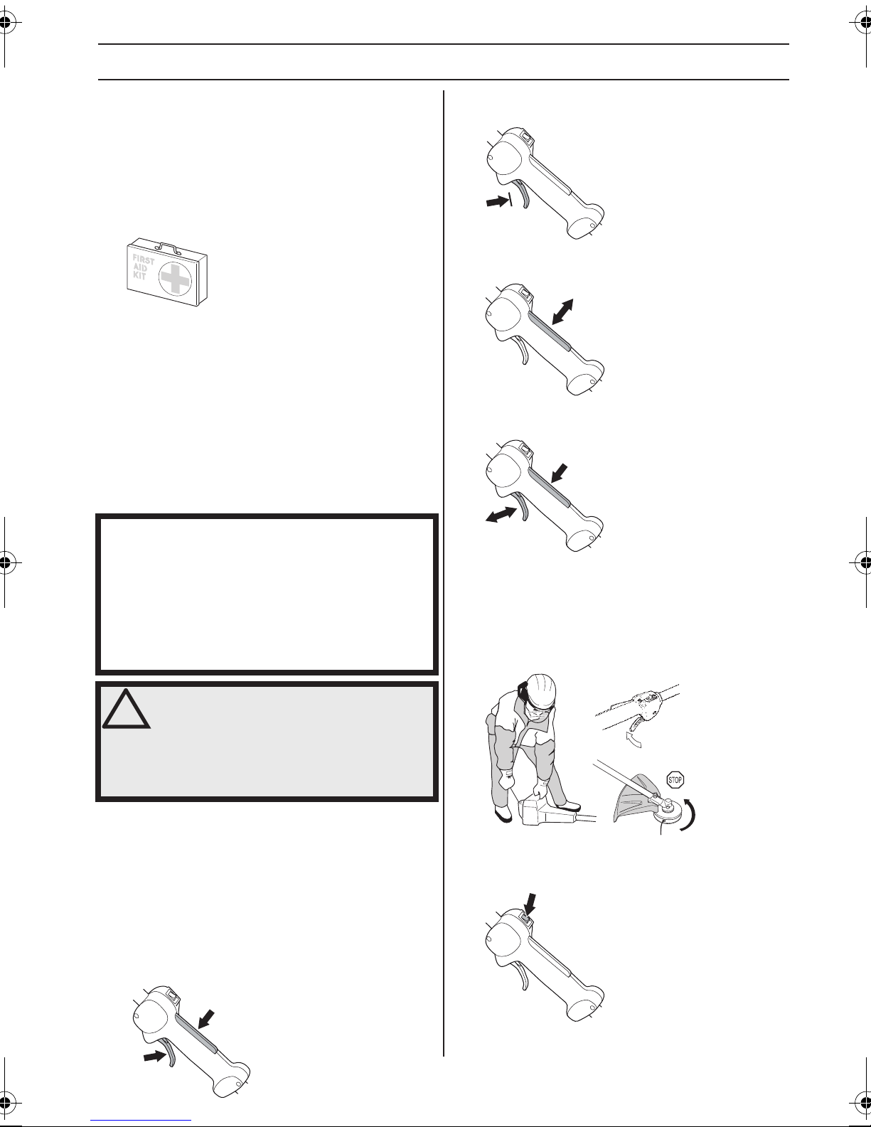
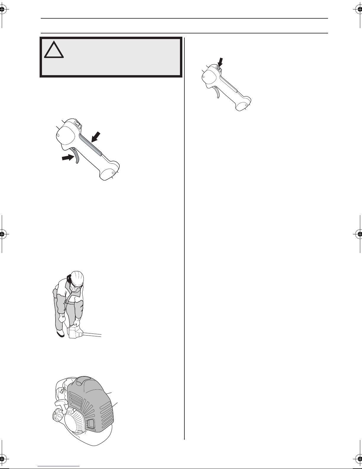
Throttle lockout
The throttle lockout is designed to prevent accidental
operation of the throttle control. When you press the lock
(A) (i.e. when you grasp the handle) it releases the throttle
control (B). When you release the handle the throttle
control and the throttle lockout both move back to their
original positions. This movement is controlled by two
independent return springs. This arrangement means that
the throttle control is automatically locked at the idle
setting.
See instructions under the heading Start. Start the
machine and apply full throttle. Release the throttle and
check that the cutting attachment stops and remains at a
standstill. If the cutting attachment rotates with the throttle
in the idle position then the carburettor idle setting must
be checked. See instructions under the heading
Maintenance.
Stop switch
Use the stop switch to switch off the engine.
A
B
Start the engine and make sure the engine stops when
you move the stop switch to the stop setting.
English – 7
Page 8
GENERAL SAFETY PRECAUTIONS
Cutting attachment guard
This guard is intended to prevent loose objects from being
thrown towards the operator. The guard also protects the
operator from accidental contact with the cutting
attachment.
Check that the guard is undamaged and not cracked.
Replace the guard if it has been exposed to impact or is
cracked.
Always use the recommended guard for the cutting
attachment you are using. See chapter on Technical data.
WARNING! Never use a cutting
!
attachment without an approved guard.
See the chapter on Technical data. If an
incorrect or faulty guard is fitted this can
cause serious personal injury.
Regularly check the vibration damping units for cracks or
deformation. Check that the vibration damping element is
undamaged and securely attached.
WARNING! Overexposure to vibration can
!
lead to circulatory damage or nerve
damage in people who have impaired
circulation. Contact your doctor if you
experience symptoms of overexposure to
vibration. These symptoms include
numbness, loss of feeling, tingling,
pricking, pain, loss of strength, changes
in skin colour or condition. These
symptoms normally appear in the fingers,
hands or wrists.
Muffler
The muffler is designed to keep noise levels to a minimum
and to direct exhaust fumes away from the user.
Vibration damping system
Your machine is equipped with a vibration damping
system that is designed to minimize vibration and make
operation easier.
Use of incorrectly wound cord or an incorrect cutting
attachment increases the level of vibration. See
instructions under the heading Cutting equipment.
The machine´s vibration damping system reduces the
transfer of vibration between the engine unit and the
machine´s shaft unit.
For mufflers it is very important that you follow the
instructions on checking, maintaining and servicing your
machine.
Never use a machine that has a faulty muffler.
Regularly check that the muffler is securely attached to
the machine.
8 – English
WARNING! The inside of the muffler
!
contain chemicals that may be
carcinogenic. Avoid contact with these
elements in the event of a damaged
muffler.
Page 9

GENERAL SAFETY PRECAUTIONS
WARNING! Bear in mind that:
!
The exhaust fumes from the engine are
hot and may contain sparks which can
start a fire. Never start the machine
indoors or near combustible material!
Locking nut
A locking nut is used to secure some types of cutting
attachment.
Cutting equipment
This section describes how to choose and maintain your
cutting equipment in order to:
• Reduce the risk of blade thrust.
• Obtain maximum cutting performance.
• Extend the life of cutting equipment.
IMPORTANT!
Only use cutting attachments with the guards we
recommend! See the chapter on Technical data.
Refer to the instructions for the cutting attachment to
check the correct way to load the cord and the correct
cord diameter.
Keep the teeth of the blade correctly sharpened! Follow
our recommendations. Also refer to the instructions on
the blade packaging.
WARNING! Always stop the engine
!
before doing any work on the cutting
attachment. This continues to rotate even
after the throttle has been released.
Ensure that the cutting attachment has
stopped completely and disconnect the
spark plug cap before you start to work
on it.
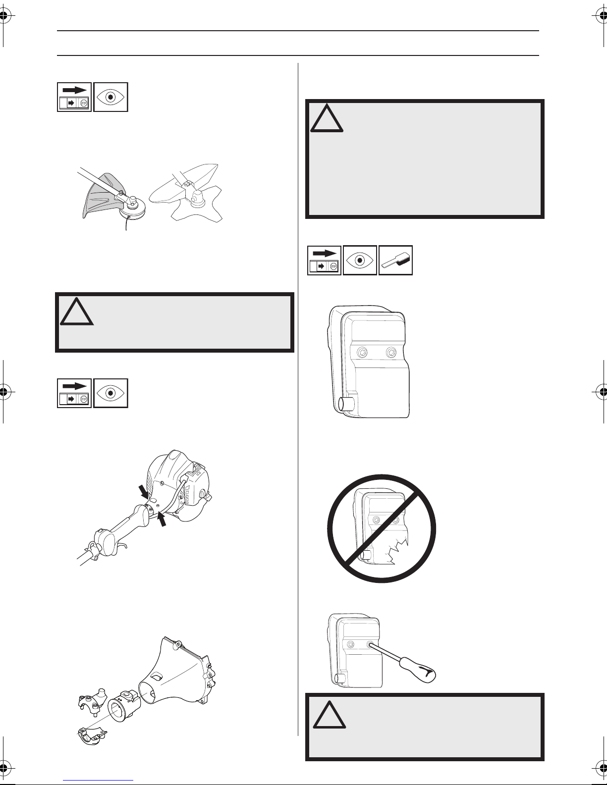
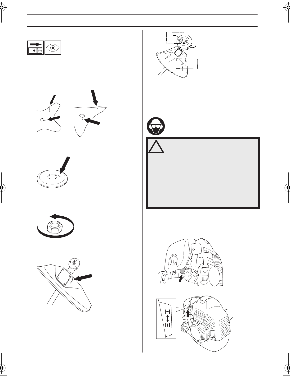
When fitting, tighten the nut in the opposite direction to the
direction of rotation of the cutting attachment. To remove
it, undo the nut in the same direction as the cutting
attachment rotates. (CAUTION! The nut has a left-hand
thread.)
When loosening and tightening the saw blade nut, there
is a risk of injury from the teeth of the saw blade. You
should therefore always ensure that your hand is shielded
by the blade guard when doing this. Always use a socket
spanner with a shaft that is long enough to allow this. The
arrow in the diagram shows the area where you should
operate the socket spanner when loosening or tightening
the nut.
The nylon lining inside the locking nut must not be so worn
that you can turn it by hand. The lining should offer a
resistance of at least 1.5 Nm. The nut should be replaced
after it has been put on approx. 10 times.
WARNING! Using an incorrect cutting
!
attachment or an incorrectly sharpened
blade increases the risk of blade thrust.
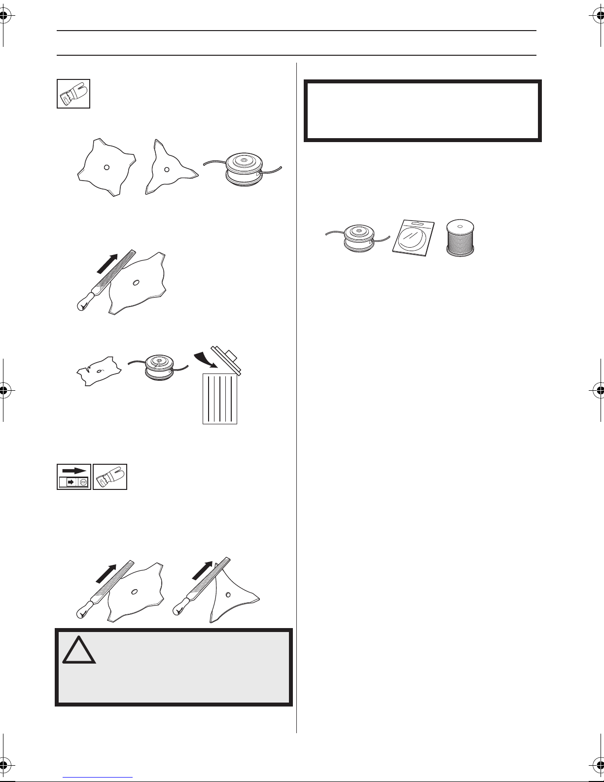
Cutting equipment
Grass blades and grass knifes are intended for cutting
coarse grass.
A trimmer head is intended for trimming grass.
English – 9
Page 10
GENERAL SAFETY PRECAUTIONS
General rules
Only use cutting attachments with the guards we
recommend! See the chapter on Technical data.
Keep the teeth of the blade correctly sharpened! Follow
our instructions and use the recommended file gauge. An
incorrectly sharpened or damaged blade increases the
risk of accidents.
Check the cutting attachment for damage or cracks. A
damaged cutting attachment should always be replaced.
Trimmer head
IMPORTANT!
Always ensure the trimmer cord is wound tightly and
evenly around the drum, otherwise the machine will
generate harmful vibration.
• Only use the recommended trimmer heads and
trimmer cords. These have been tested by the
manufacturer to suit a particular engine size. This is
especially important when a fully automatic trimmer
head is used. Only use the recommended cutting
attachment. See the chapter on Technical data.
• Smaller machines generally require small trimmer
heads and vice versa. This is because when clearing
using a cord the engine must throw out the cord
radially from the trimmer head and overcome the
resistance of the grass being cleared.
• The length of the cord is also important. A longer cord
requires greater engine power than a shorter cord of
the same diameter.
• Make sure that the cutter on the trimmer guard is
intact. This is used to cut the cord to the correct length.
• To increase the life of the cord it can be soaked in
water for a couple of days before use. This will make
the cord tougher so that it lasts longer.
Sharpening grass knifes and grass
blades
• See the cutting attachment packaging for correct
sharpening instructions. Sharpen blades and knifes
using a single-cut flat file.
• Sharpen all edges equally to maintain the balance of
the blade.
WARNING! Always discard a blade that is
!
bent, twisted, cracked, broken or
damaged in any other way. Never attempt
to straighten a twisted blade so that it
can be reused. Only use original blades
of the specified type.
10 – English
Page 11
ASSEMBLY
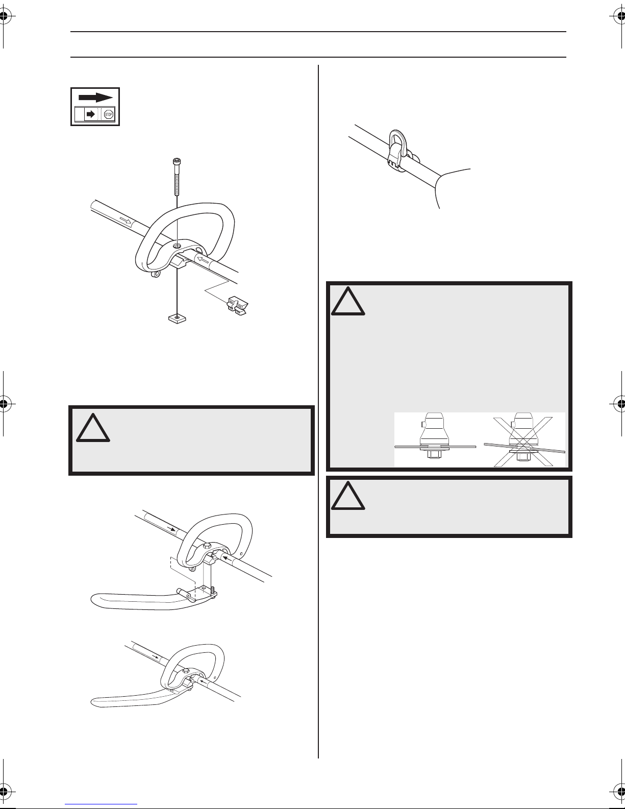
Fitting the loop handle
• Clip the loop handle onto the shaft. Note that the loop
handle must be fitted between the arrows on the shaft.
• Slide the spacer into the slot in the loop handle. Fit the
nut, knob and screw. Do not overtighten.
• Now adjust the trimmer to give a comfortable working
position. Tighten the bolt.
Fitting the J-handle
Fitting the suspension ring
Fit the suspension ring between the rear handle and the
loop handle. Position the hanging ring so that the machine
is balanced and comfortable to work with.
Use the harness and attach it to the suspension ring when
using grass blades.
Assembling the cutting
equipment
WARNING!
!
When fitting the cutting attachment it is
extremely important that the raised
section on the drive disc/support flange
engages correctly in the centre hole of the
cutting attachment. If the cutting
attachment is fitted incorrectly it can
result in serious and/or fatal personal
injury.
WARNING! Only grass blades/grass
!
Attach the J-handle to the loop handle using the three
screws, as shown.
Now carry out fine adjustment to give yourself a
comfortable working position. Tighten the screws.
cutters or trimmer heads/plastic blades
may be used when the J-handle is fitted.
Saw blades must never be used with the
J-handle.
WARNING! Never use a cutting
!
attachment without an approved guard.
See the chapter on Technical data. If an
incorrect or faulty guard is fitted this can
cause serious personal injury.
English – 11
Page 12
ASSEMBLY
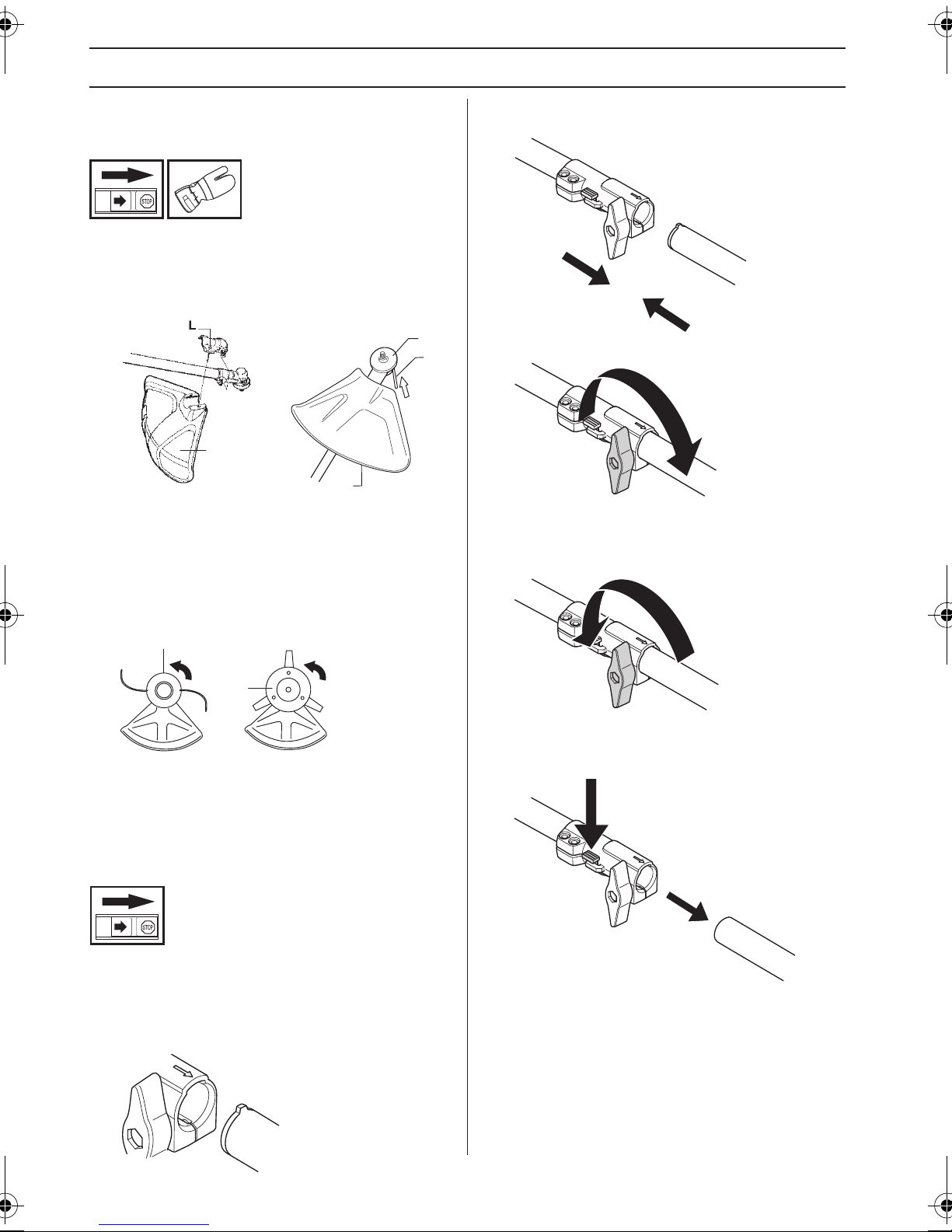
Fitting the trimmer guard and
trimmer head
• Fit the correct trimmer guard (A) for use with the
trimmer head. Hook the trimmer guard/combination
guard onto the fitting on the shaft and secure with the
bolt (L).
B
C
A
A
• Fit the drive disc (B) on the output shaft.
• Turn the output shaft until one of the holes in the drive
disc aligns with the corresponding hole in the gear
housing.
• Insert the locking pin (C) in the hole to lock the shaft.
• Screw on the trimmer head/plastic blades (H) in the
opposite direction to the direction of rotation.
H
• Push the attachment into the coupling until the
attachment snaps into place.
• Before using the unit, tighten the knob securely.
Dismantling
• Loosen the coupling by turning the knob (at least 3
times).
H
• To dismantle, follow the instructions in the reverse
order.
Assembling and dismantling the
two-piece shaft
(GC2225C)
Assembly
• Loosen the coupling by turning the knob.
• Align the tab of the attachment (A) with the arrow on
the coupling (B).
B
A
Push and hold the button (C). While securely holding the
engine end, pull the attachment straight out of the
coupling.
C
12 – English
Page 13
ASSEMBLY
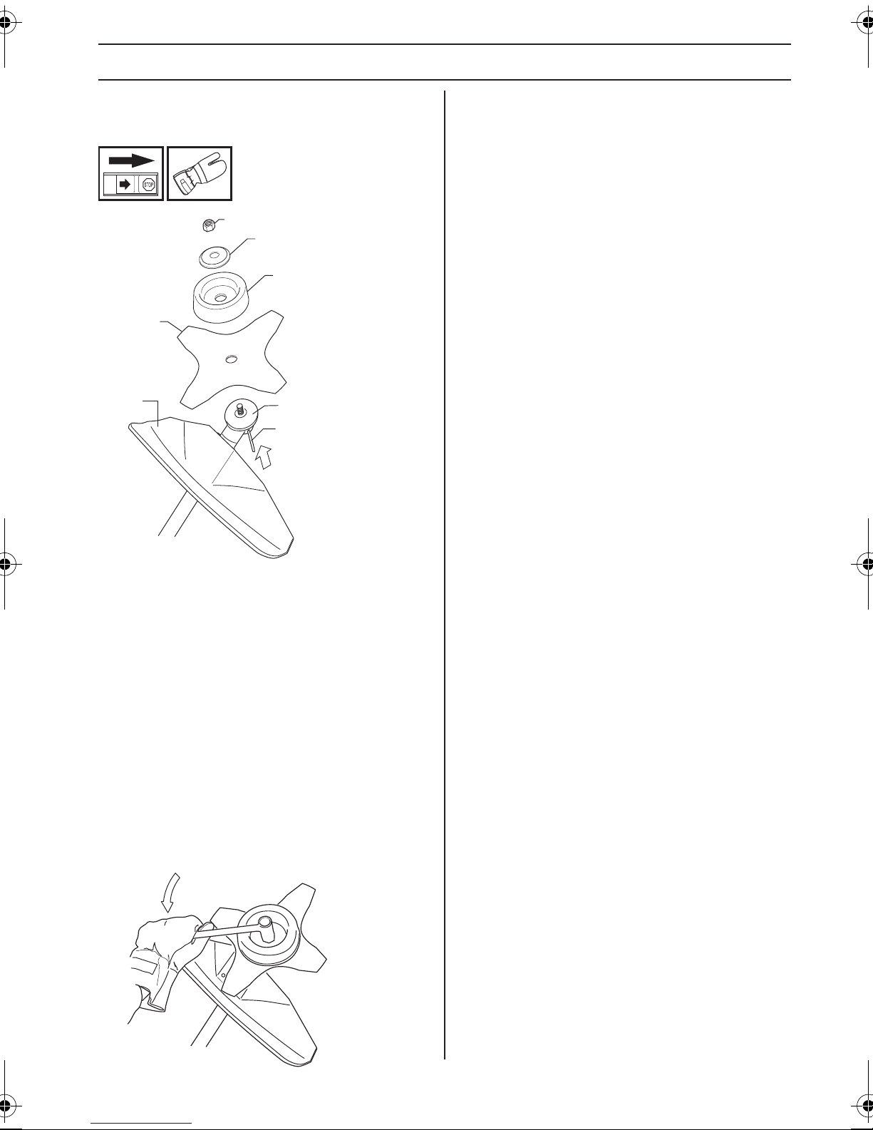
Fitting a blade guard, grass blade
and grass cutter
G
F
E
D
A
• Hook the blade guard/combination guard (A) onto the
fitting on the shaft and secure with the bolt.
CAUTION! Use the recommended blade guard. See the
Technical data section.
• Fit the drive disc (B) on the output shaft.
• Turn the output shaft until one of the holes in the drive
disc aligns with the corresponding hole in the gear
housing.
• Insert the locking pin (C) in the hole to lock the shaft.
• Place the blade (D), support cup (E) and support
flange (F) on the output shaft.
• Fit the nut (G). The nut must be tightened to a torque
of 35-50 Nm (3.5-5 kpm). Use the socket spanner in
the tool kit. Hold the shaft of the spanner as close to
the blade guard as possible. To tighten the nut, turn
the spanner in the opposite direction to the direction
of rotation (Caution! left-hand thread).
B
C
English – 13
Page 14
FUEL HANDLING
Fuel safety
Never start the machine:
1 If you have spilled fuel on it. Wipe off the spillage and
allow remaining fuel to evaporate.
2 If you have spilled fuel on yourself or your clothes,
change your clothes. Wash any part of your body that
has come in contact with fuel. Use soap and water.
3 If the machine is leaking fuel. Check regularly for
leaks from the fuel cap and fuel lines.
Transport and storage
• Store and transport the machine and fuel so that there
is no risk of any leakage or fumes coming into contact
with sparks or open flames, for example, from
electrical machinery, electric motors, electrical relays/
switches or boilers.
• When storing and transporting fuel always use
approved containers intended for this purpose.
• When storing the machine for long periods the fuel
tank must be emptied. Contact your local petrol
station to find out where to dispose of excess fuel.
• Ensure the machine is cleaned and that a complete
service is carried out before long-term storage.
• The transport guard must always be fitted to the
cutting attachment when the machine is being
transported or in storage.
• Secure the machine during transport.
• In order to prevent unintentional starting of the engine,
the spark plug cap must always be removed during
long-term storage, if the machine is not under close
supervision and when performing all service
measures.
WARNING! Take care when handling fuel.
!
Bear in mind the risk of fire, explosion
and inhaling fumes.
Fuel
CAUTION! The machine is equipped with a two-stroke
engine and must always be run using a mixture of petrol
and two-stroke oil. It is important to accurately measure
the amount of oil to be mixed to ensure that the correct
mixture is obtained. When mixing small amounts of fuel,
even small inaccuracies can drastically affect the ratio of
the mixture.
WARNING! Fuel and fuel fumes are
!
highly inflammable and can cause
serious injury when inhaled or allowed to
come in contact with the skin. For this
reason observe caution when handling
fuel and make sure there is adequate
ventilation.
Petrol
CAUTION! Always use a quality petrol/oil mixture at least
90 octane (RON). If your machine is equipped with a
catalytic converter (see chapter on Technical data) always
use a good quality unleaded petrol/oil mixture. Leaded
petrol will destroy the catalytic converter.
Use low-emission petrol, also known as alkylate petrol, if
it is available.
Ethanol blended fuel, E10 may be used (max 10%
ethanol blend). Using ethanol blends higher than E10 will
create lean running condition which can cause engine
damage.
• The lowest octane recommended is 90 (RON). If you
run the engine on a lower octane grade than 90 socalled knocking can occur. This gives rise to a high
engine temperature, which can result in serious
engine damage.
• When working at continuous high revs a higher octane
rating is recommended.
Two-stroke oil
• For best results and performance use JONSERED
two-stroke engine oil, which is specially formulated for
our air-cooled two-stroke engines.
• Never use two-stroke oil intended for water-cooled
engines, sometimes referred to as outboard oil (rated
TCW).
• Never use oil intended for four-stroke engines.
• A poor oil quality and/or too high oil/fuel ratio may
jeopardise function and decrease the life time of
catalytic converters.
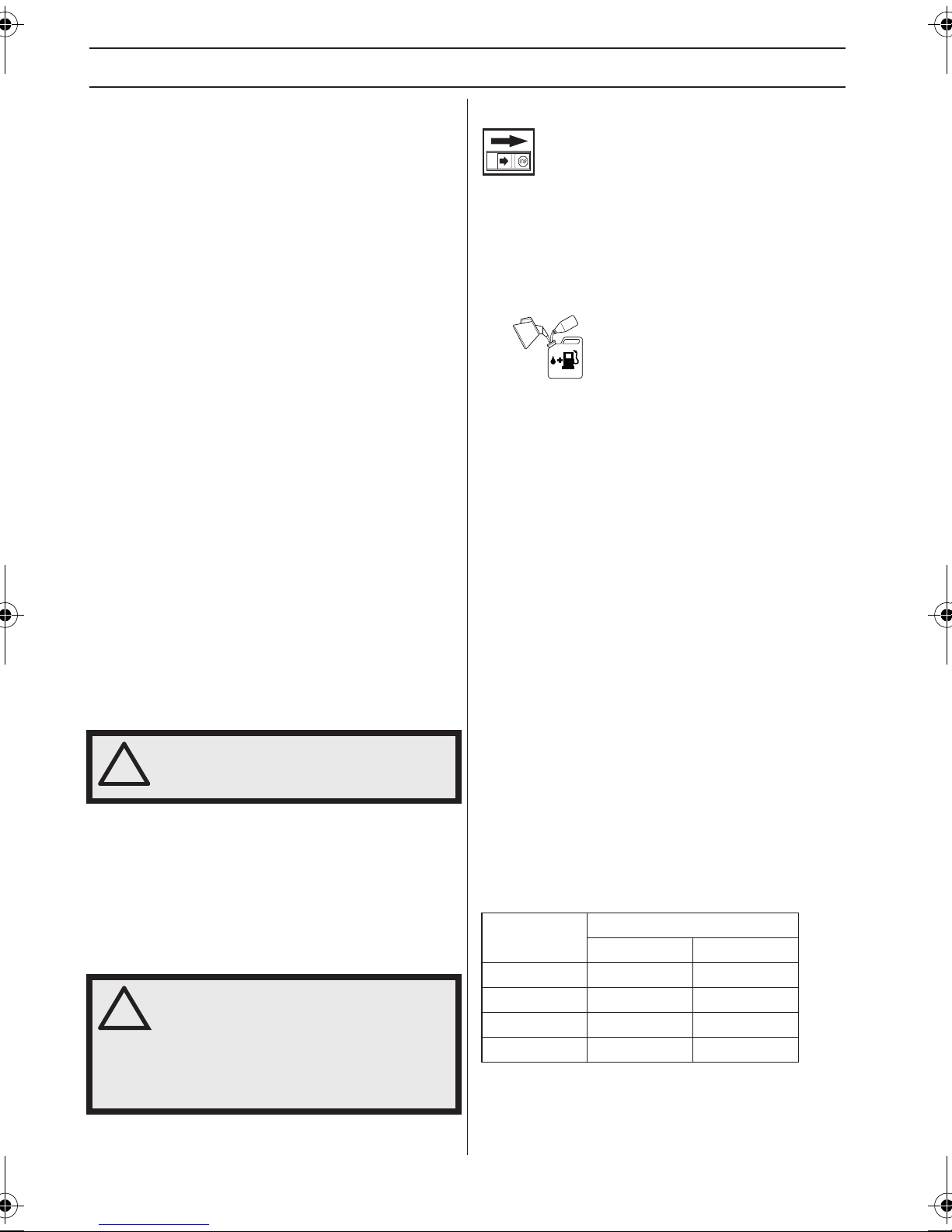
• Mixing ratio
1:50 (2%) with JONSERED two-stroke oil.
1:33 (3%) with oils class JASO FB or ISO EGB
formulated for air-cooled, two-stroke engines.
Petrol, litre
5 0,10 0,15
10 0,20 0,30
15 0,30 0,45
20 0,40 0,60
Two-stroke oil, litre
2% (1:50) 3% (1:33)
14 – English
Page 15
FUEL HANDLING
Mixing
• Always mix the petrol and oil in a clean container
intended for fuel.
• Always start by filling half the amount of the petrol to
be used. Then add the entire amount of oil. Mix
(shake) the fuel mixture. Add the remaining amount of
petrol.
• Mix (shake) the fuel mixture thoroughly before filling
the machine’s fuel tank.
• Do not mix more than one month’s supply of fuel at a
time.
• If the machine is not used for some time the fuel tank
should be emptied and cleaned.
• Clean the area around the fuel cap. Contamination in
the tank can cause operating problems.
• Ensure that the fuel is well mixed by shaking the
container before filling the tank.
Fueling
!
WARNING! Taking the following
precautions, will lessen the risk of fire:
Mix and pour fuel outdoors, where there
are no sparks or flames.
Do not smoke or place hot objects near
fuel.
Always shut off the engine before
refuelling.
Always stop the engine and let it cool for
a few minutes before refuelling.
When refuelling, open the fuel cap slowly
so that any excess pressure is released
gently.
Tighten the fuel cap carefully after
refuelling.
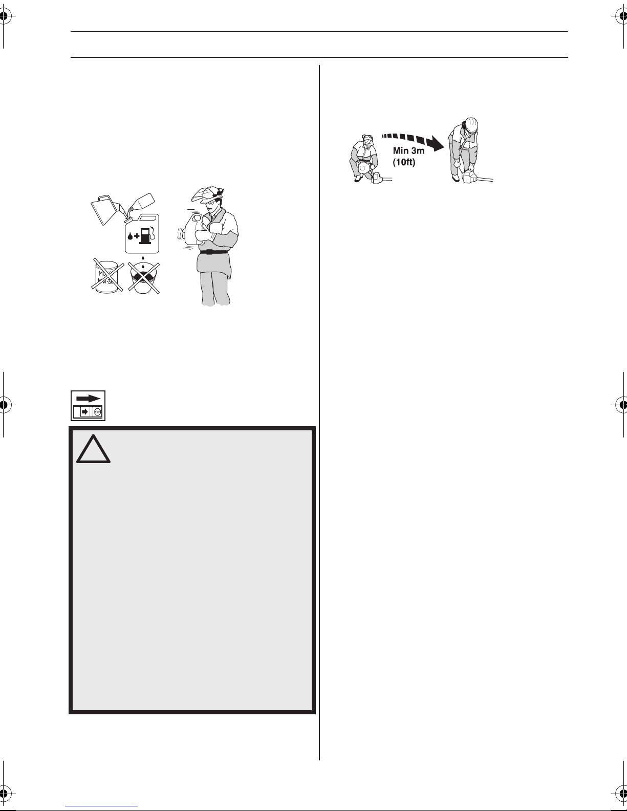
Always move the machine away from the
refuelling area and source before
starting.
• If you have spilled fuel on it. Wipe off the spillage and
allow remaining fuel to evaporate.
• Always use a fuel container with an anti-spill valve.
English – 15
Page 16
STARTING AND STOPPING
Check before starting
Check the blade to ensure that no cracks have formed at
the bottom of the teeth or by the centre hole. The most
common reason why cracks are formed is that sharp
corners have been formed at the bottom of the teeth while
sharpening or that the blade has been used with dull
teeth. Discard a blade if cracks are found.
• Never use the machine without a guard nor with a
defective guard.
• All covers must be correctly fitted and undamaged
before you start the machine.
Starting and stopping
• Check that the support flange is not cracked due to
fatigue or due to being tightened too much. Discard
the support flange if it is cracked.
Ensure the locking nut has not lost its captive force. The
nut lock should have a locking force of at least 1.5 Nm.
The tightening torque of the locking nut should be 35-50
Nm.
Check that the blade guard is not damaged or cracked.
Replace the blade guard if it is exposed to impact or is
cracked.
WARNING! The complete clutch cover and
!
shaft must be fitted before the machine is
started, otherwise the clutch can come
loose and cause personal injury.
Always move the machine away from the
refuelling area and source before starting.
Place the machine on a flat surface.
Ensure the cutting attachment cannot
come into contact with any object.
Make sure no unauthorised persons are in
the working area. Otherwise there is a risk
of serious personal injury. The safety
distance is 15 meters.
Starting
Primer bulb: Press the air purge repeatedly until fuel
begins to fill the bulb. The bulb need not be completely
filled.
• Check that the trimmer head and trimmer guard are
not damaged or cracked. Replace the trimmer head or
trimmer guard if they have been exposed to impact or
are cracked.
16 – English
Choke: Move choke control up to choke position.
Page 17
STARTING AND STOPPING
WARNING! When the engine is started
!
Hold the body of the machine on the ground using your
left hand (CAUTION! Not with your foot!).
Firmly grasp throttle lockout (A) and throttle control (B)
with left hand, pull the starter knob quickly until engine
attempts to start, or maximum 5 pulls.
with the choke in either the choke or
start throttle positions the cutting
attachment will start to rotate
immediately.
A
B
Never twist the starter cord around your hand.
After engine attempts to start, or maximum 5 pulls, move
the choke lever down to run position.
Grasp the throttle lockout (A) and the throttle trigger (B)
and repeat pulling the cord until the engine starts. Make
sure that the machine reaches full throttle and then
release the throttle trigger. Once the engine starts, allow
the engine to warm up for 30 seconds before applying full
throttle.
CAUTION! Do not pull the starter cord all the way out and
do not let go of the starter handle when the cord is fully
extended. This can damage the machine.
Stopping
Stop the engine by switching off the ignition.
CAUTION! The stop switch automatically returns to the
start position. In order to prevent unintentional starting,
the spark plug cap must be removed from the spark plug
when assembling, checking and/or performing
maintenance.
CAUTION! Do not put any part of your body in marked
area. Contact can result in burns to the skin, or electrical
shock if the spark plug cap has been damaged. Always
use gloves. Do not use a machine with damaged spark
plug cap.
English – 17
Page 18
WORKING TECHNIQUES
General working instructions
IMPORTANT!
This section describes the basic safety precautions for
working with brush cutters and trimmers.
If you encounter a situation where you are uncertain
how to proceed you should ask an expert. Contact your
dealer or your service workshop.
Avoid all usage which you consider to be beyond your
capability.
You must understand the difference between forestry
clearing, grass clearing and grass trimming before use.
Grass blades or grass knives may only be used when
the J-handle is fitted. Clearing blades must never be
used with the J-handle. Use the harness and attach it to
the suspension ring when using grass blades.
Basic safety rules
1 Look around you:
• To ensure that people, animals or other things cannot
affect your control of the machine.
• To ensure that people, animals, etc., do not come into
contact with the cutting attachment or loose objects
that are thrown out by the cutting attachment.
• CAUTION! Do not use the machine unless you are
able to call for help in the event of an accident.
2 Inspect the working area. Remove all loose objects,
such as stones, broken glass, nails, steel wire, string,
etc. that could be thrown out or become wrapped
around the cutting attachment.
3 Do not use the machine in bad weather, such as
dense fog, heavy rain, strong wind, intense cold, etc.
Working in bad weather is tiring and often brings
added risks, such as icy ground, unpredictable felling
direction, etc.
4 Make sure you can move and stand safely. Check the
area around you for possible obstacles (roots, rocks,
branches, ditches, etc.) in case you have to move
suddenly. Take great care when working on sloping
ground.
6 Always hold the machine with both hands. Hold the
machine on the right side of your body.
7 Keep the cutting attachment below waist level.
8 Switch off the engine before moving to another area.
Fit the transport guard before carrying or transporting
the equipment any distance.
9 Never put the machine down with the engine running
unless you have it in clear sight.
WARNING! Neither the operator of the
!
!
machine nor anyone else may attempt to
remove the cut material while the engine
is running or the cutting equipment is
rotating, as this can result in serious
injury.
Stop the engine and cutting equipment
before you remove material that has
wound around the blade shaft as
otherwise there is a risk of injury. The
bevel gear can get hot during use and
may remain so for a while afterwards. You
could get burnt if you touch it.
WARNING! Watch out for thrown objects.
Always wear approved eye protection.
Never lean over the cutting attachment
guard. Stones, rubbish, etc. can be
thrown up into the eyes causing
blindness or serious injury.
Keep unauthorised persons at a
distance. Children, animals, onlookers
and helpers should be kept outside the
safety zone of 15 metres. Stop the
machine immediately if anyone
approaches. Never swing the machine
around without first checking behind you
to make sure no-one is within the safety
zone.
5 Keep a good balance and a firm foothold.
18 – English
Page 19
WORKING TECHNIQUES
Basic working techniques
Always slow the engine to idle speed after each working
operation. Long periods at full throttle without any load on
the engine can lead to serious engine damage.
WARNING! Sometimes branches or
!
!
grass get caught between the guard and
cutting attachment. Always stop the
engine before cleaning.
WARNING! Machines fitted with saw
blades or grass blades can be thrown
violently to the side when the blade
comes into contact with a fixed object.
This is called blade thrust. A blade thrust
can be violent enough to cause the
machine and/or operator to be propelled
in any direction, and possibly lose
control of the machine. Blade thrust can
occur without warning if the machine
snags, stalls or binds. Blade thrust is
more likely to occur in areas where it is
difficult to see the material being cut.
Avoid cutting with the area of the blade
between the 12 o'clock and 3 o'clock
positions. Because of the speed of
rotation of the blade, blade thrust can
occur if you attempt to cut thick stems
with this area of the blade.
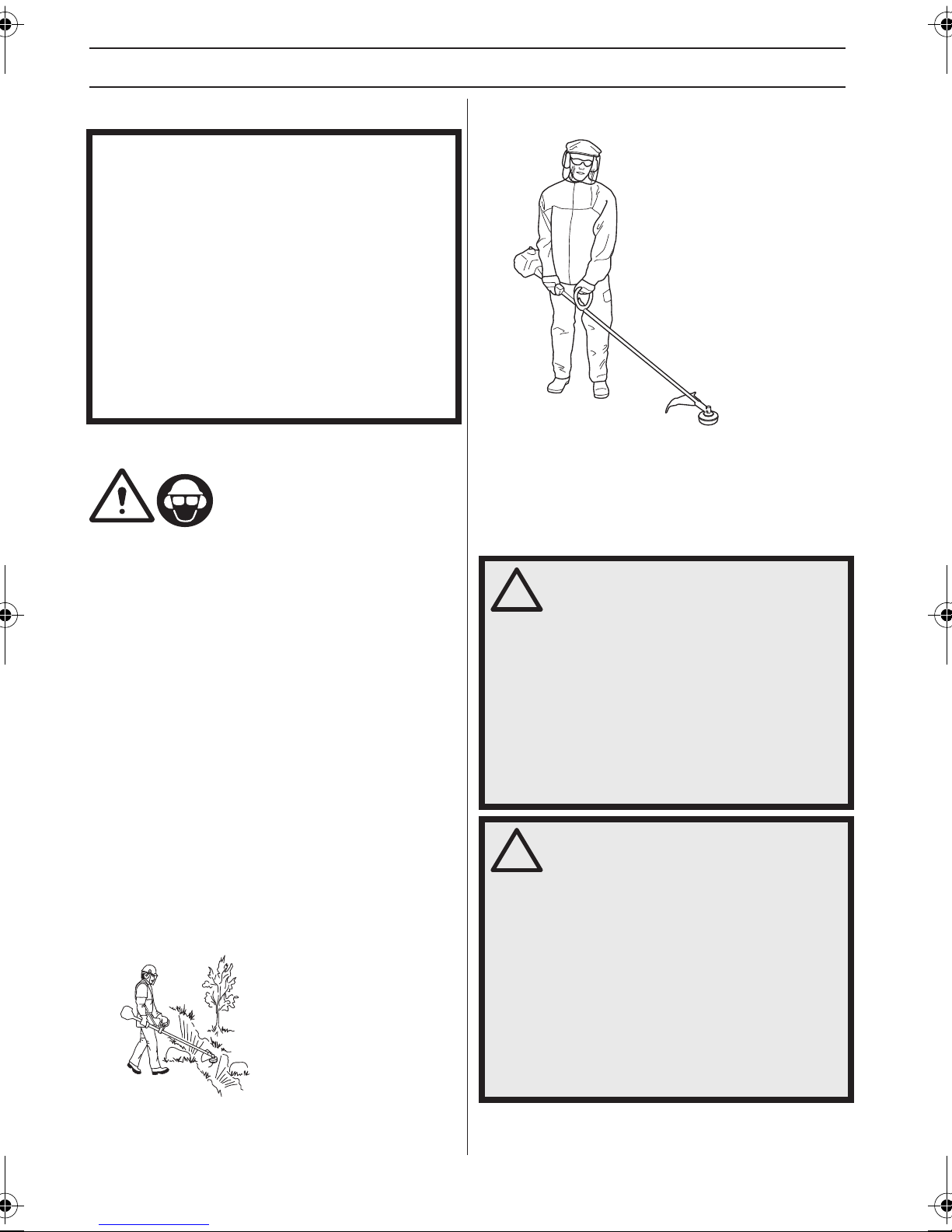
Grass clearing using a grass blade
• Grass blades and grass knifes must not be used on
woody stems.
• A grass blade is used for all types of tall or coarse
grass.
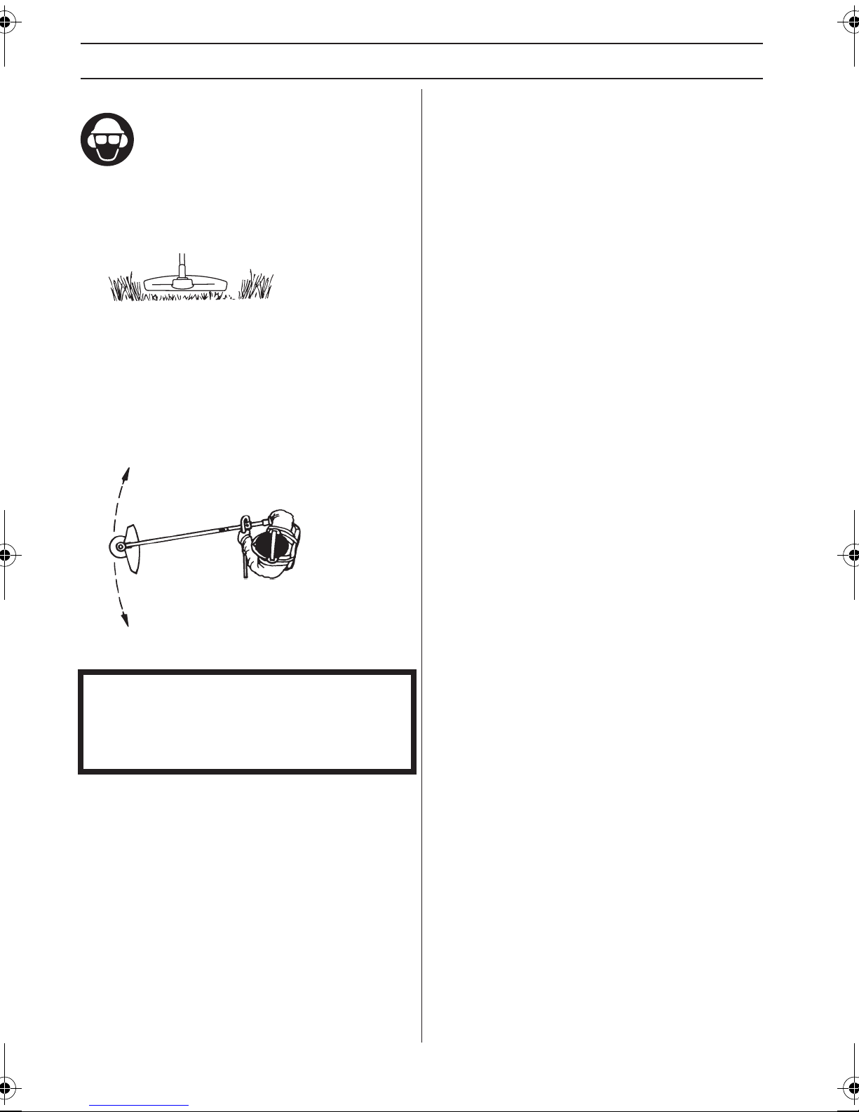
• The grass is cut down with a sideways, swinging
movement, where the movement from right-to-left is
the clearing stroke and the movement from left-toright is the return stroke. Let the left-hand side of the
blade (between 8 and 12 o’clock) do the cutting.
• Let the support cup rest lightly against the ground. It
is used to protect the blade from hitting the ground.
• Reduce the risk of material wrapping around the blade
by following these instructions:
1Always work at full throttle.
2Avoid the previously cut material during the return
stroke.
• Stop the engine, unclip the harness and place the
machine on the ground before you start to collect the
cut material.
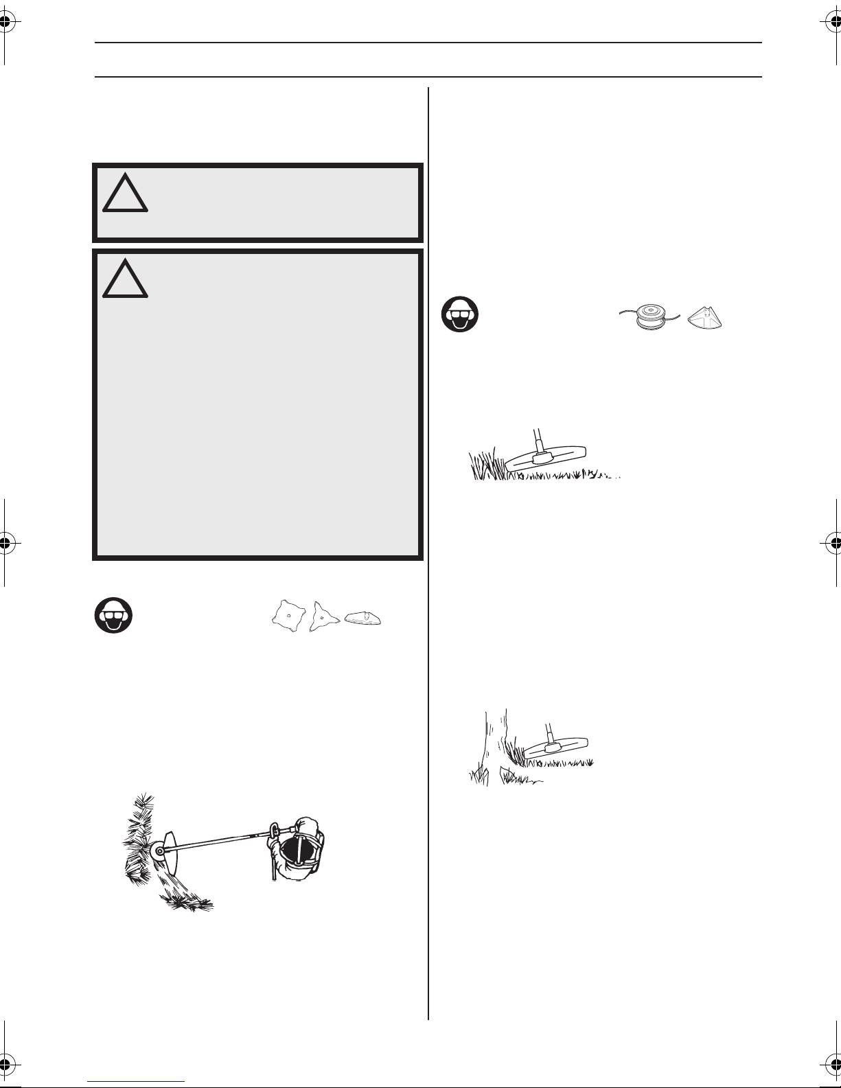
Grass trimming with a trimmer head
Trimming
• Hold the trimmer head just above the ground at an
angle. It is the end of the cord that does the work. Let
the cord work at its own pace. Never press the cord
into the area to be cut.
• The cord can easily remove grass and weeds up
against walls, fences, trees and borders. However it
can also damage sensitive bark on trees and bushes,
and damage fence posts.
• Reduce the risk of damaging plants by shortening the
cord to 10-12 cm and reducing the engine speed.
Clearing
• The clearing technique removes all unwanted
vegetation. Keep the trimmer head just above the
ground and tilt it. Let the end of the cord strike the
ground around trees, posts, statues and the like.
CAUTION! This technique increases the wear on the
cord.
• The cord wears quicker and must be fed forward more
often when working against stones, brick, concrete,
metal fences, etc., than when coming into contact with
trees and wooden fences.
• When trimming and clearing, you should use less than
full throttle (80%) so that the cord lasts longer and to
reduce the wear on the trimmer head.
• If the blade is angled to the left when clearing grass,
the grass will collect in a line, which makes it easier to
collect, e.g. by raking.
• Try to work rhythmically. Stand firmly with your feet
apart. Move forward after the return stroke and stand
firmly again.
English – 19
Page 20
WORKING TECHNIQUES
Cutting
• The trimmer is ideal for cutting grass that is difficult to
reach using a normal lawn mower. Keep the cord
parallel to the ground when cutting. Avoid pressing the
trimmer head against the ground as this can ruin the
lawn and damage the tool.
• Do not allow the trimmer head to constantly come into
contact with the ground during normal cutting.
Constant contact of this type can cause damage and
wear to the trimmer head.
Sweeping
• The fan effect of the rotating cord can be used for
quick and easy clearing up. Hold the cord parallel to
and above the area to be swept and move the tool side
to side.
• When cutting and sweeping you should use full
throttle to obtain the best results.
IMPORTANT!
To avoid unbalance and vibrations in handles trimmer
head cover need to be cleaned every time cord is
refilled. In addition, check other part of the head if
needed to be cleaned.
20 – English
Page 21
MAINTENANCE
Carburettor
Your Jonsered product has been designed and
manufactured to specifications that reduce harmful
exhaust fumes. The engine will be run in after it has used
8-10 tanks of fuel. To ensure that the engine runs at peak
performance and produces as little harmful exhaust
fumes as possible after the running-in period, ask your
dealer/service workshop (which has a rev counter for this
purpose) to adjust your carburettor.
Basic setting
• The basic carburettor settings are adjusted during
testing at the factory. The basic setting is richer than
the optimal setting and should be maintained for the
first few hours the machine is in use. The carburettor
should then be finely adjusted. Fine adjustment
should be carried out by a skilled technician.
CAUTION! If the cutting attachment rotates when the
engine is idling the idle adjustment screw T should be
turned anti-clockwise until the cutting attachment stops.
Adjustment of the idle speed
Before any adjustments are made, make sure that the air
filter is clean and the air filter cover is fitted.
Adjust the idle speed using the idle adjustment screw T, if
it is necessary to readjust. First turn the idle adjustment
screw T clockwise until the cutting attachment starts to
rotate. Then turn the screw anticlockwise until the cutting
attachment stops. The idle speed is correctly adjusted
when the engine will run smoothly in every position. The
idle speed should also be well below the speed at which
the cutting attachment starts to rotate.
T
Cooling system
To keep the working temperature as low as possible the
machine is equipped with a cooling system.
1
2
The cooling system consists of:
1 Check and clean the cooling air openings.
2 Air intake through the crankcase (inside the tank).
Clean the cooling system with a brush once a week, more
often in demanding conditions. A dirty or blocked cooling
system results in the machine overheating which causes
damage to the piston and cylinder.
Spark plug
The spark plug condition is influenced by:
• Incorrect carburettor adjustment.
• An incorrect fuel mixture (too much or incorrect type
of oil).
• A dirty air filter.
These factors cause deposits on the spark plug
electrodes, which may result in operating problems and
starting difficulties.
If the machine is low on power, difficult to start or runs
poorly at idle speed: always check the spark plug first
before taking any further action. If the spark plug is dirty,
clean it and check that the electrode gap is 0,65 mm. The
spark plug should be replaced after about a month in
operation or earlier if necessary.
Recommended idle speed: See the Technical data
section.
WARNING! If the idle speed cannot be
!
adjusted so that the cutting attachment
stops, contact your dealer/service
workshop. Do not use the machine until it
has been correctly adjusted or repaired.
0,65
CAUTION! Always use the recommended spark plug
type! Use of the wrong spark plug can damage the piston/
cylinder. Check that the spark plug is fitted with a
suppressor.
English – 21
Page 22
MAINTENANCE
Two-piece shaft
(GC2225C)
The drive shaft end in the lower shaft should be lubricated
with grease every 30 hours. There is a risk that the drive
shaft ends (splined coupling) on models with two-piece
shafts will seize if they are not lubricated regularly.
Air filter
The air filter must be regularly cleaned to remove dust
and dirt in order to avoid:
• Carburettor malfunctions
• Starting problems
• Loss of engine power
• Unnecessary wear to engine parts.
• Excessive fuel consumption.
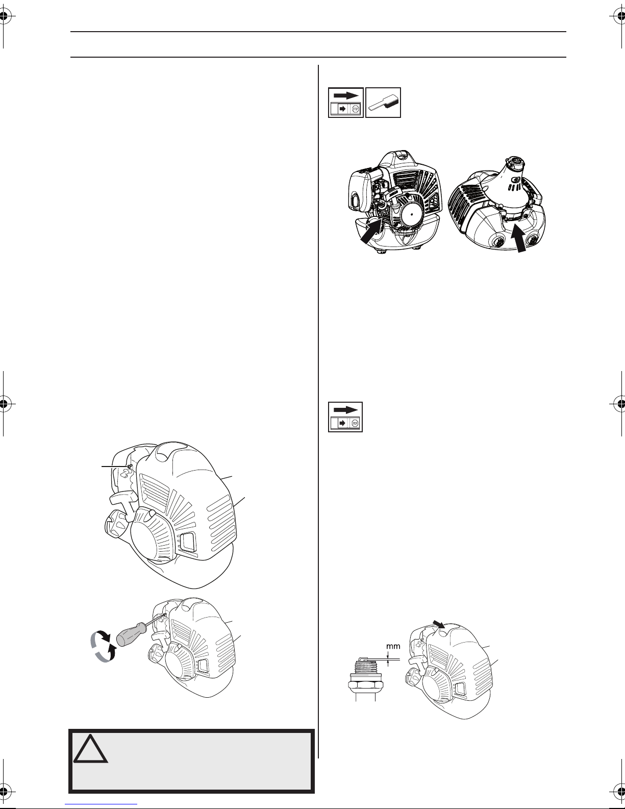
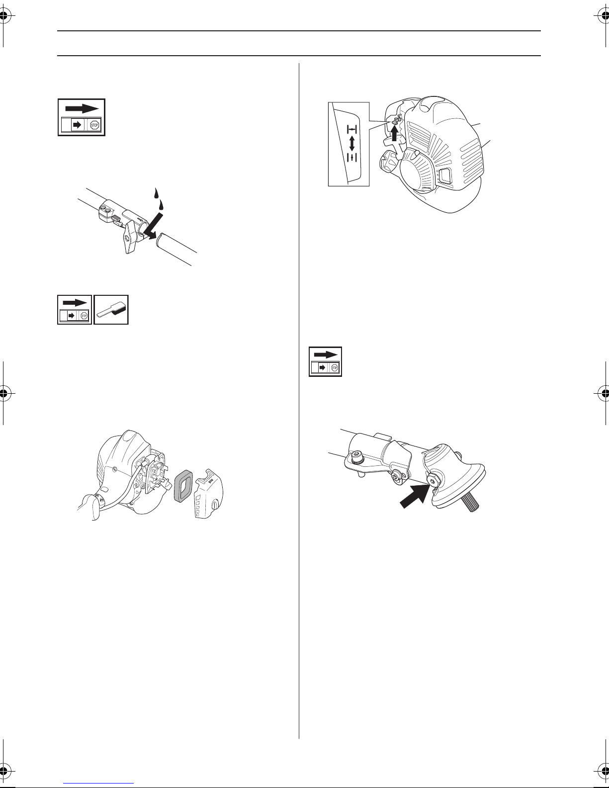
Cleaning the air filter
Close the choke valve by moving the choke control up.
Remove the air filter cover and take out the filter. Wash it
clean in warm, soapy water. Clean also the inside of the
filter cover by using air or a brush. Ensure that the filter is
dry before refitting it.
An air filter that has been in use for a long time cannot be
cleaned completely. The filter must therefore be replaced
with a new one at regular intervals. A damaged air filter
must always be replaced. Damaged, very dirty, or fuelsoaked air filter must always be replaced.
Bevel gear
The bevel gear is filled with the right quantity of grease at
the factory. However, before using the machine you
should check that the bevel gear is filled three-quarters
full with grease. Use JONSERED special grease.
Clean the filter every 25 hours, or more regularly if
conditions are exceptionally dusty.
22 – English
The grease in the bevel gear does not normally need to
be changed except if repairs are carried out.
Page 23

MAINTENANCE
Maintenance schedule
The following is a list of the maintenance steps that must be performed on the machine. Most of the items are described
in the Maintenance section. The user must only carry out the maintenance and service work described in this Operator's
Manual. More extensive work must be carried out by an authorized service workshop.
Maintenance
Clean the outside of the machine. X
Make sure the throttle trigger lock and the throttle function
correctly from a safety point of view.
Check that the stop switch works correctly. X
Check that the cutting attachment does not rotate at idle. X
Clean the air filter. Replace if necessary. X
Check that the guard is undamaged and not cracked. Replace
the guard if it has been exposed to impact or is cracked.
Check that the trimmer head is undamaged and not cracked.
Replace the trimmer head if necessary.
Check that nuts and screws are tight. X
Check that there are no fuel leaks from the engine, tank or fuel
lines.
Clean the machine’s cooling system. X
Check the starter and starter cord. X
Check that the vibration damping elements are not damaged. X
Clean the outside of the spark plug. Remove it and check the
electrode gap. Adjust the gap to 0,65 mm or replace the spark
plug. Check that the spark plug is fitted with a suppressor.
Clean the outside of the carburettor and the space around it. X
Check that the bevel gear is filled three-quarters full with
lubricant. Fill if necessary using special grease.
Check the fuel filter for contamination and the fuel hose for cracks
or other defects. Replace if necessary.
Check all cables and connections. X
Check the clutch, clutch springs and the clutch drum for wear.
Replace if necessary by an autorized service workshop.
Replace the spark plug. Check that the spark plug is fitted with a
suppressor.
Daily
maintenance
X
X
X
X
Weekly
maintenance
X
X
Monthly
maintenance
X
X
X
English – 23
Page 24

TECHNICAL DATA
Technical data
GC2225 GC2225C
Engine
Cylinder displacement, cm
Cylinder bore, mm 34,0 34,0
Stroke, mm 28 28
Idle speed, rpm 3000 3000
Recommended max. speed, rpm 9500±500 9500±500
Speed of output shaft, rpm 6500 6500
Max. engine output, acc. to ISO 8893, kW/ rpm 1,0/8500 1,0/8500
Catalytic converter muffler No No
Speed-regulated ignition system Yes Yes
Ignition system
Manufacturer/type of ignition system IKEDA/UK IKEDA/UK
Spark plug NGK BPMR8Y NGK BPMR8Y
Electrode gap, mm 0,65 0,65
Fuel and lubrication system
Manufacturer/type of carburettor Walbro WYA-218 Walbro WYA-218
Fuel tank capacity, litre 0,65 0,65
Weight
Weight without fuel, cutting attachment and guard, kg 4,4 4,7
Noise emissions
(see note 1)
Sound power level, measured dB (A) 109 109
Sound power level, guaranteed L
Noise levels
(see note 2)
Equivalent sound pressure level at the operator’s ear, measured
according to EN/ISO 11806 and ISO 7917, dB(A), min./max.:
Vibration levels
(see note 3)
Equivalent vibration levels (a
according to EN ISO 11806 and ISO 22867, m/s
Equipped with trimmer head (original), left/right 4,4/2,5 4,3/2,6
3
dB (A) 111 111
WA
) at handles, measured
hv,eq
25,4 25,4
101 101
2
Note 1: Noise emissions in the environment measured as sound power (LWA) in conformity with EC directive 2000/14/
EC. Reported sound power level for the machine has been measured with the original cutting attachment that gives the
highest level. The difference between guaranteed and measured sound power is that the guaranteed sound power also
includes dispersion in the measurement result and the variations between different machines of the same model
according to Directive 2000/14/EC.
Note 2: Reported data for equivalent sound pressure level for the machine has a typical statistical dispersion (standard
deviation) of 1 dB (A).
Note 3: Reported data for equivalent vibration level has a typical statistical dispersion (standard deviation) of 1 m/s
24 – English
2
.
Page 25

TECHNICAL DATA
GC2225, GC2225C
Approved accessories Type
Blade shaft thread M10
Plastic blades Polytrim 503 93 42-02
Grass blade/grass cutter
Trimmer head
GC 2225C
Approved accessories Art No. Use with
Cultivator attachment with shaft CA 150 537 42 54-02 GC 2225C
Hedge trimmer attachment with shaft HA 110 537 19 66-03 GC 2225C
Hedge trimmer attachment with shaft HA 850 537 19 66-04 GC 2225C
Clean sweep attachment with shaft SR600 537 19 67-02 GC 2225C
Trimmer attachment with shaft TA 850 537 35 35-02 GC 2225C
Saw attachment with shaft PA 1100 537 18 33-24 GC 2225C
Blower attachment BAC 952 71 19-21 GC 2225C
Grass 255-4 1" (Ø 255 4-teeth) 503 93 42-02
Grass 255-8 (Ø 255 8 teeth) 503 93 42-04
Fix 35 503 93 42-04
Tap-N-Go 25 (L) 503 93 42-02
Tap-N-Go 35 / Tap-N-Go 35 Spin 503 93 42-04
Support cup Fixed
Cutting attachment guard, Art.
no.
English – 25
Page 26

TECHNICAL DATA
EC Declaration of Conformity
(Applies to Europe only)
We, Husqvarna AB, SE-561 82 Huskvarna, Sweden, tel: +46-36-146500, declare that the grass trimmers Jonsered
GC2225, GC2225C with serial numbers dating from 2013 onwards (the year is clearly stated on the rating plate, followed
by the serial number), comply with the requirements of the COUNCIL’S DIRECTIVE:
- of May 17, 2006 ”relating to machinery” 2006/42/EC
- of December 15, 2004 ”relating to electromagnetic compatibility” 2004/108/EC.
- of May 8, 2000 ”relating to the noise emissions in the environment” 2000/14/EC. Conformity assessment according
to Annex V.
For information relating to noise emissions, see the Technical data chapter.
The following harmonised standards have been applied: EN ISO 12100:2010, EN ISO 11806-1:2011, ISO 14982:2009,
CISPR 12:2009
SMP Svensk Maskinprovning AB, Box 7035, SE-750 07 Uppsala, Sweden, has carried out voluntary type approval for
Husqvarna AB. The certificates have the numbers: SEC/13/2387 - GC 2225, GC 2225C
Huskvarna, 21 December 2013
Per Gustafsson, Development manager (Authorized representative for Husqvarna AB and responsible for technical
documentation.)
26 – English
Page 27
EXPLICATION DES SYMBOLES
Symboles
AVERTISSEMENT! Les
débroussailleuses et les coupe-herbes
peuvent être dangereux! Une utilisation
erronée ou négligente peut
occasionner des blessures graves,
voire mortelles pour l’utilisateur ou d’autres personnes. Il
est extrêmement important de lire et de comprendre le
contenu de ce manuel de l’opérateur.
Lire attentivement et bien assimiler
le manuel d’utilisation avant
d’utiliser la machine.
Toujours utiliser:
• Portez un casque de protection là
où il y a risque de chute d’objets
• Protecteurs d’oreilles homologués
• Des protège-yeux homologués
Régime maxi. recommandé de
l’axe sortant, tr/min
10000
Attention: projections et ricochets.
L’utilisateur de la machine doit
s’assurer qu’aucune personne ou
animal ne s’approche à moins de 15
15 m
50FT
15
m
5
0
FT
mètres pendant le travail.
Utiliser des bottes antidérapantes et
stables.
Pompe à carburant
Émissions sonores dans
l’environnement selon la directive de
la Communauté européenne. Les
émissions de la machine sont
indiquées au chapitre
Caractéristiques techniques et sur
les autocollants.
Les autres symboles/autocollants présents sur
la machine concernent des exigences de certification
spécifiques à certains marchés.
Arrêter le moteur en déplaçant
l’interrupteur d’arrêt en position
d’arrêt. REMARQUE! L'interrupteur
d'arrêt se remet automatiquement en
position de démarrage. Toujours
retirer le chapeau de bougie de la bougie lors du
montage, contrôle et/ou entretien, afin d'éviter tout
démarrage accidentel.
Toujours porter des gants de
protection homologués.
Les machines équipées de lames
d’éclaircissage ou de disques à
herbe peuvent être projetées
violemment d’un côté quand la lame
heurte un objet fixe. Ce phénomène
est appelé rebond. La lame peut amputer un bras ou une
jambe. Veiller à ce que les personnes et les animaux
soient toujours à au moins 15 mètres de la machine.
Flèches indiquant les limites quant à
l’emplacement de la fixation de la
poignée.
Toujours porter des gants de
protection homologués.
Un nettoyage régulier est
indispensable.
Examen visuel.
French – 27
Page 28
SOMMAIRE
Sommaire Contrôler les points suivants
EXPLICATION DES SYMBOLES
Symboles .............................................................. 27
SOMMAIRE
Sommaire ............................................................. 28
Contrôler les points suivants avant la mise en
marche: ................................................................. 28
INTRODUCTION
Cher client, ............................................................ 29
QUELS SONT LES COMPOSANTS?
Quels sont les composants? ................................. 30
INSTRUCTIONS GÉNÉRALES DE SÉCURITÉ
Important! ............................................................. 31
Équipement de protection personnelle ................. 31
Équipement de sécurité de la machine ................. 32
Équipement de coupe ........................................... 35
MONTAGE
Montage de la poignée en boucle ......................... 37
Montage de la poignée en J ................................ 37
Montage de l’œillet de suspension ....................... 37
Montage de l’équipement de coupe ...................... 37
Montage de la protection de la tête et de la tête de
désherbage .......................................................... 38
Montage et démontage d’un tube de transmission
démontable ........................................................... 38
Montage du protège-lame, de la lame à herbe et
du couteau à herbe ............................................... 39
MANIPULATION DU CARBURANT
Sécurité carburant ................................................ 40
Carburant .............................................................. 40
Remplissage de carburant .................................... 41
DÉMARRAGE ET ARRÊT
Contrôles avant la mise en marche ...................... 42
Démarrage et arrêt ............................................... 42
TECHNIQUES DE TRAVAIL
Méthodes de travail ............................................... 44
ENTRETIEN
Carburateur ........................................................... 47
Système de refroidissement ................................. 47
Bougie ................................................................... 47
Tube de transmission démontable ........................ 48
Filtre à air .............................................................. 48
Schéma d’entretien ............................................... 49
CARACTÉRISTIQUES TECHNIQUES
Caractéristiques techniques ................................. 50
Déclaration CE de conformité ............................... 51
avant la mise en marche:
Lire attentivement le manuel d’utilisation.
AVERTISSEMENT! Une exposition
!
!
!
prolongée au bruit risque de causer des
lésions auditives permanentes. Toujours
utiliser des protecteurs d'oreille agréés.
AVERTISSEMENT! Ne jamais modifier
sous aucun prétexte la machine sans
l’autorisation du fabricant. N’utiliser que
des accessoires et des pièces d’origine.
Des modifications non-autorisées et
l’emploi d’accessoires non-homologués
peuvent provoquer des accidents graves
et même mortels, à l’utilisateur ou
d’autres personnes.
AVERTISSEMENT! Utilisés de manière
négligente ou erronée, les
débroussailleuses et les coupe-herbes
peuvent devenir des outils dangereux
pouvant occasionner des blessures
graves, voire mortelles pour l’utilisateur
ou d’autres. Il est très important de lire
attentivement et de bien comprendre les
instructions contenues dans ce mode
d’emploi.
28 – French
Page 29

INTRODUCTION
Cher client,
Félicitations pour ce choix d’un produit Jonsered.
Nous sommes persuadés que vous apprécierez la qualité et les performances de nos produits pendant de longues
années. L’achat d’un de nos produits vous garantit une assistance professionnelle au niveau du service et des
réparations en cas de besoin. Si la machine n’a pas été achetée chez un de nos revendeurs autorisés, demandez à un
revendeur l’adresse de l’atelier d’entretien le plus proche.
Nous espérons que cette machine vous donnera toute satisfaction et qu’elle vous accompagnera pendant de longues
années. N’oubliez pas que ce manuel d’utilisation est important. En suivant les instructions qu’il contient (utilisation,
révision, entretien, etc.), il est possible d’allonger considérablement la durée de vie de la machine et d’augmenter sa
valeur sur le marché de l’occasion. En cas de vente de la machine, ne pas oublier de remettre le manuel d’utilisation au
nouveau propriétaire.
Bonne chance avec votre nouveau produit Jonsered!
Jonsered travaille continuellement au développement de ses produits et se réserve le droit d’en modifier, entre autres,
la conception et l’aspect sans préavis.
French – 29
Page 30
QUELS SONT LES COMPOSANTS?
10
17
18
24
25
19
4
3
2
1
4
23
26
8
6
29
5
28
27
31
21
11
9
7
30
13
14
16
12
15
20
22
Quels sont les composants?
1 Tête de désherbage
2 Ravitaillement en lubrifiant, renvoi d’angle
3 Renvoi d’angle
4 Protection pour l’équipement de coupe
5 Tube de transmission
6 Poignée anneau
7 Commande de l’accélération
8 Bouton d’arrêt
9 Blocage de l’accélération
10 Chapeau de bougie et bougie
11 Capot de cylindre
12 Poignée de lanceur
13 Réservoir d’essence
14 Carter de filtre à air
15 Pompe à carburant
16 Commande de starter
17 Contre-écrou
18 Bride de support
19 Toc d’entraînement
20 Clé universelle
21 Clé à six pans
22 Goupille d’arrêt
23 Manuel d’utilisation
24 Bol de garde au sol
25 Lame
26 Raccord du tube de transmission (GC2225C)
27 Poignée en J
28 Réglage de poignée
29 Œillet de suspension
30 Harnais
31 Dispositif de protection pour le transport
30 – French
Page 31

INSTRUCTIONS GÉNÉRALES DE SÉCURITÉ
Important! Équipement de protection
IMPORTANT!
La machine est conçue uniquement pour le désherbage.
La législation nationale ou locale peut réglementer
l’utilisation. Respectez la législation en vigueur.
Les seuls accessoires pouvant utiliser le moteur comme
source motrice sont les équipements de coupe que nous
recommandons au chapitre Caractéristiques techniques.
Éviter d’utiliser la machine en cas de fatigue,
d’absorption d’alcool ou de prise de médicaments
susceptibles d’affecter l’acuité visuelle, le jugement ou la
maîtrise du corps.
Utiliser les équipements de protection personnelle. Voir
au chapitre ”Équipement de protection personnelle”.
Ne jamais utiliser une machine qui a été modifiée au point
de ne plus être conforme au modèle original.
Ne jamais utiliser une machine qui n’est pas en parfait
état de marche. Appliquer les instructions de
maintenance et d’entretien ainsi que les contrôles de
sécurité indiqués dans ce manuel d’utilisation. Certaines
mesures de maintenance et d’entretien doivent être
confiées à un spécialiste dûment formé et qualifié. Voir
les instructions à la section Maintenance.
Tous les capots, toutes les protections et toutes les
poignées doivent avoir été montées avant d’utiliser la
machine. Vérifier que le capuchon de la bougie et le câble
d’allumage sont en bon état afin d’éliminer tout risque de
choc électrique.
L’utilisateur de la machine doit s’assurer qu’aucune
personne ou animal ne s’approche à moins de 15 mètres
pendant le travail. Lorsque plusieurs utilisateurs
travaillent dans une même zone, il convient d’observer
une distance de sécurité d'au moins 15 mètres.
AVERTISSEMENT! Cette machine génère
!
!
un champ électromagnétique en
fonctionnement. Ce champ peut dans
certaines circonstances perturber le
fonctionnement d’implants médicaux
actifs ou passifs. Pour réduire le risque de
blessures graves ou mortelles, les
personnes portant des implants médicaux
doivent consulter leur médecin et le
fabricant de leur implant avant d’utiliser
cette machine.
AVERTISSEMENT! Faire tourner un
moteur dans un local fermé ou mal aéré
peut causer la mort par asphyxie ou
empoisonnement au monoxyde de
carbone.
personnelle
IMPORTANT!
Utilisés de manière négligente ou erronée, les
débroussailleuses et les coupe-herbes peuvent devenir
des outils dangereux pouvant occasionner des blessures
graves, voire mortelles pour l’utilisateur ou d’autres. Il est
très important de lire attentivement et de bien
comprendre les instructions contenues dans ce mode
d’emploi.
Un équipement de protection personnelle homologué
doit impérativement être utilisé lors de tout travail avec la
machine. L’équipement de protection personnelle
n’élimine pas les risques mais réduit la gravité des
blessures en cas d’accident. Demander conseil au
concessionnaire afin de choisir un équipement adéquat.
AVERTISSEMENT! Soyez toujours
!
CASQUE
Portez un casque de protection là où il y a risque de chute
d’objets
PROTÈGE-OREILLES
Porter des protège-oreilles ayant un effet atténuateur
suffisant.
PROTÈGE-YEUX
Toujours porter des protège-yeux homologués. L’usage
d’une visière doit toujours s’accompagner du port de
lunettes de protection homologuées. Par lunettes de
protection homologuées, on entend celles qui sont en
conformité avec les normes ANSI Z87.1 (États-Unis) ou
EN 166 (pays de l’UE).
attentifs aux signaux d’alerte ou aux
appels en portant des protège-oreilles.
Enlevez-les sitôt le moteur arrêté.
AVERTISSEMENT! Ne jamais laisser des
!
enfants utiliser la machine ou se tenir à
proximité. La machine est équipée d'un
interrupteur d'arrêt à détente et peut être
démarrée par une activation à faible
vitesse et de faible puissance de la
poignée de démarrage ; dans certaines
circonstances, de jeunes enfants peuvent
produire la force nécessaire au démarrage
de la machine. Ceci peut entraîner un
risque de blessures personnelles. Retirer
donc le chapeau de bougie lorsque la
machine n'est pas sous surveillance.
GANTS
Au besoin, utiliser des gants, notamment lors du montage
de l’équipement de coupe.
French – 31
Page 32

INSTRUCTIONS GÉNÉRALES DE SÉCURITÉ
BOTTES
Utiliser des bottes avec coquille en acier et semelle
antidérapante
HABITS
Porter des vêtements fabriqués dans un matériau
résistant à la déchirure, éviter les vêtements
excessivement amples qui risqueraient de se prendre
dans les broussailles et les branches. Toujours utiliser des
pantalons longs et robustes. Ne pas porter de bijoux, de
shorts ou de sandales, et ne pas marcher pieds-nus.
Veiller à ce que les cheveux ne tombent pas sur les
épaules.
PREMIERS SECOURS
Une trousse de premiers secours doit toujours être
disponible.
Blocage de l’accélération
Le blocage de l’accélération a pour but d’empêcher toute
accélération involontaire. Une fois le cliquet (A) enfoncé
dans la poignée (= en tenant celle-ci), la commande de
l’accélération (B) se trouve libérée. Quand la poignée est
relâchée, la commande de l’accélération et le cliquet
reviennent en position initiale, Ce retour en position
initiale s’effectue grâce à deux ressorts de rappel
indépendants. Cette position signifie que la commande
d’accélération est alors automatiquement bloquée sur le
ralenti.
A
B
Vérifier d’abord que la commande de l’accélération est
bloquée en position de ralenti quand le blocage de
l’accélération est en position initiale.
Équipement de sécurité de la
machine
Ce chapitre présente les équipements de sécurité de la
machine, leur fonction, comment les utiliser et les
maintenir en bon état. Voir au chapitre Quels sont les
composants? pour trouver leur emplacement sur la
machine.
La durée de vie de la machine risque d'être écourtée et le
risque d'accidents accru si la maintenance de la machine
n'est pas effectuée correctement et si les mesures
d'entretien et/ou de réparation ne sont pas effectuées de
manière professionnelle. Pour obtenir de plus amples
informations, contacter l'atelier de réparation le plus
proche.
IMPORTANT!
L’entretien et la réparation de la machine exigent une
formation spéciale. Ceci concerne particulièrement
l’équipement de sécurité de la machine. Si les contrôles
suivants ne donnent pas un résultat positif, s’adresser à
un atelier spécialisé. L’achat de l’un de nos produits offre
à l’acheteur la garantie d’un service et de réparations
qualifiés. Si le point de vente n’assure pas ce service,
s’adresser à l’atelier spécialisé le plus proche.
AVERTISSEMENT! Ne jamais utiliser une
!
machine dont les équipements de sécurité
sont défectueux. Contrôler et entretenir
les équipements de sécurité de la
machine conformément aux instructions
données dans ce chapitre. Si les contrôles
ne donnent pas de résultat positif, confier
la machine à un atelier spécialisé.
Appuyer sur le blocage de l’accélération et vérifier qu’il
revient de lui-même en position initiale quand il est
relâché.
Vérifier que le blocage de l’accélération, la commande
d’accélération et leurs ressorts de rappel fonctionnent
correctement.
32 – French
Page 33

INSTRUCTIONS GÉNÉRALES DE SÉCURITÉ
Voir le chapitre Démarrage. Démarrer la machine et
donner les pleins gaz. Relâcher l’accélérateur et
s’assurer que l’équipement de coupe s’arrête et qu’il reste
immobile. Si l’équipement de coupe tourne lorsque
l’accélérateur est au régime de ralenti, contrôler le
réglage du ralenti du carburateur. Voir le chapitre
Entretien.
Bouton d’arrêt
Le bouton d’arrêt est utilisé pour arrêter le moteur.
Système anti-vibrations
La machine est équipée d’un système anti-vibrations
conçu pour assurer une utilisation aussi confortable que
possible.
L’utilisation d’un fil mal enroulé ou d’un équipement de
coupe inadéquat augmente le niveau de vibration. Voir les
instructions au chapitre Équipement de coupe.
Le système anti-vibrations réduit la transmission des
vibrations entre l’unité moteur et l’unité de l’arbre de la
machine.
Mettre le moteur en marche et s’assurer qu’il s’arrête
lorsque le bouton d’arrêt est amené en position d’arrêt.
Protection pour l’équipement de coupe
Cette protection a pour but d’empêcher que des objets ne
soient projetés en direction de l’utilisateur. La protection
prévient aussi le contact entre l’utilisateur et l’équipement
de coupe.
S’assurer que la protection est intacte et qu’elle ne
présente pas de fissures. Remplacer la protection si elle
a subi des coups ou si elle présente des fissures.
Toujours utiliser la protection recommandée prévue pour
l’équipement de coupe en question. Voir Caractéristiques
techniques.
AVERTISSEMENT! Un équipement de
!
coupe ne peut en aucun cas être utilisé si
une protection homologuée n’a pas été
préalablement montée. Voir le chapitre
Caractéristiques techniques. La mise en
place d’une protection erronée ou
défectueuse peut provoquer des
blessures graves.
Vérifier régulièrement l’état des éléments afin de détecter
fissures et déformations. Vérifier que les éléments antivibrations sont entiers et solidement fixés.
AVERTISSEMENT! Une exposition
!
excessive aux vibrations peut entraîner
des troubles circulatoires ou nerveux
chez les personnes sujettes à des
troubles cardio-vasculaires. Consulter
un médecin en cas de symptômes liés
aux vibrations, tels qu’insensibilisation
ou irritation locale, douleur,
chatouillements, faiblesse musculaire,
décoloration ou modification
épidermique. Ces symptômes affectent
généralement les doigts, les mains ou
les poignets.
French – 33
Page 34

INSTRUCTIONS GÉNÉRALES DE SÉCURITÉ
Silencieux
Le silencieux est conçu pour réduire au maximum le
niveau sonore et détourner les gaz d’échappement loin
de l’utilisateur.
En ce qui concerne le silencieux, il importe de bien suivre
les instructions de contrôle, de maintenance et
d’entretien.
Ne jamais utiliser une machine dont le silencieux est
défectueux.
Contre-écrou
Un contre-écrou est utilisé pour la fixation de certains
types d’équipements de coupe.
Pose: serrer l’écrou dans le sens contraire de la rotation
de l’équipement de coupe. Dépose: desserrer l’écrou
dans le sens de la rotation de l’équipement de coupe.
(NOTA! L’écrou est fileté à gauche.)
Les dents de la lame d’éclaircissage risquent de causer
des blessures aussi bien lors du serrage que du
desserrage de l’écrou de la lame. Veiller à ce que la main
soit toujours protégée par le protège-lame lors de ces
interventions. Toujours utiliser une clé à douille munie
d’un manche assez long. La flèche sur l’illustration
indique la zone dans laquelle la clé doit être utilisée, aussi
bien pour serrer que pour desserrer l’écrou.
Vérifier régulièrement la fixation du silencieux dans la
machine.
AVERTISSEMENT! L’intérieur du
!
silencieux contient des produits
chimiques pouvant être cancérigènes.
Eviter tout contact avec ces éléments si
le silencieux est endommagé.
AVERTISSEMENT! N’oubliez pas que:
!
Les gaz d’échappement du moteur sont
très chauds et peuvent contenir des
étincelles pouvant provoquer un incendie.
Par conséquent, ne jamais démarrer la
machine dans un local clos ou à proximité
de matériaux inflammables!
L’usure du verrouillage nylon du contre-écrou ne doit pas
être telle qu’il peut se visser à l’aide des doigts. Le
verrouillage doit résister à 1,5 Nm au moins. Remplacer
le contre-écrou après une dizaine de serrages.
34 – French
Page 35

INSTRUCTIONS GÉNÉRALES DE SÉCURITÉ
Équipement de coupe
Cette section explique comment, grâce à l’utilisation du
bon équipement de coupe et grâce à un entretien correct:
• Réduire le risque de rebond de la machine.
• Obtenir la meilleure coupe possible.
• Augmenter la durée de vie de l’équipement de coupe.
IMPORTANT!
N’utiliser l’équipement de coupe qu’avec la protection
recommandée! Voir le chapitre Caractéristiques
techniques.
Voir les instructions relatives à l’équipement de coupe
pour poser correctement le fil et choisir le diamètre de fil
approprié.
Maintenir les dents de la lame correctement affûtés!
Suivre nos recommandations. Voir aussi les instructions
sur l’emballage des lames.
AVERTISSEMENT! Toujours arrêter le
!
moteur avant d’entamer des travaux sur
l’équipement de coupe. Celui-ci continue
de tourner après qu’on a relâché
l’accélérateur. S’assurer que l’équipement
de coupe est complètement immobilisé et
débrancher le câble de la bougie
d’allumage avant de commencer
l’intervention sur l’équipement de coupe.
Règles élémentaires
N’utiliser l’équipement de coupe qu’avec la protection
recommandée! Voir le chapitre Caractéristiques
techniques.
Maintenir les dents de la lame correctement affûtées!
Suivre nos instructions et utiliser le calibre d’affûtage
recommandé. Une lame mal affûtée ou endommagée
augmente les risques d’accident.
Inspecter l’équipement de coupe afin de détecter
d’éventuels dommages ou fissures. Toujours remplacer
un équipement de coupe endommagé.
AVERTISSEMENT! Un équipement de
!
coupe inadéquat ou une lame mal affûtée
augmentent les risques de rebond.
Équipement de coupe
Les lame et couteau à herbe sont destinés à la coupe de
l’herbe épaisse.
La tête de désherbage est destinée au désherbage.
Affûtage des lames et couteaux à herbe
• Voir les instructions d’affûtage sur l’emballage de
l’équipement de coupe. Les lames et couteaux
s’affûtent à l’aide d’une lime plate à taille simple.
• Limer les tranchants de manière égale afin de
préserver l’équilibre.
AVERTISSEMENT! Toujours jeter une
!
lame pliée, faussée, fissurée, cassée ou
abîmée de toute autre façon. Ne jamais
essayer de redresser une lame faussée
pour l’utiliser de nouveau. Utiliser
uniquement des lames d’origine du
modèle recommandé.
French – 35
Page 36
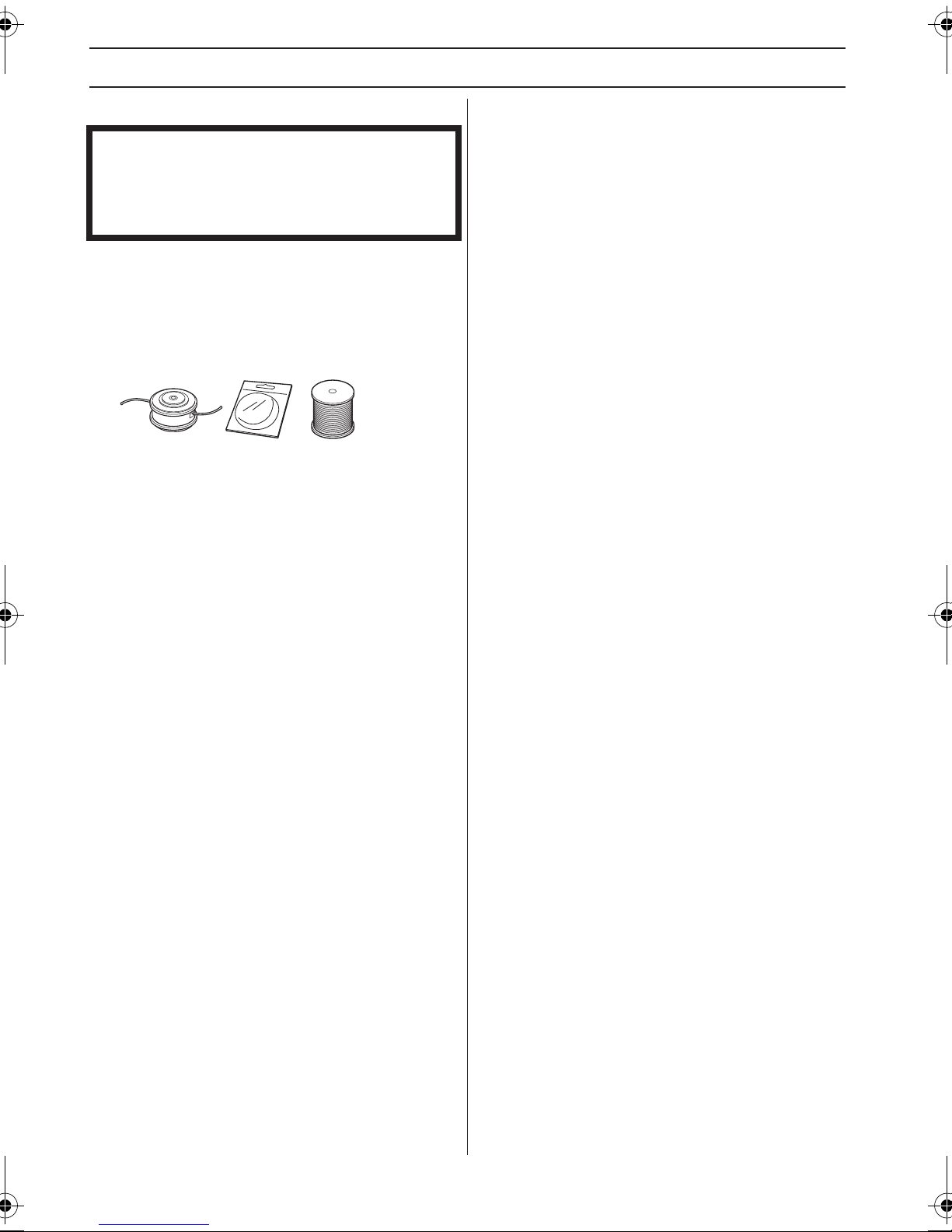
INSTRUCTIONS GÉNÉRALES DE SÉCURITÉ
Tête de désherbage
IMPORTANT!
Veiller à ce que le fil du coupe-herbe soit toujours
enroulé de manière serrée et régulière autour du
tambour, autrement la machine produit des vibrations
dangereuses pour la santé.
• N’utiliser que les têtes de désherbage et les fils
recommandés. Ils ont été testés par le fabricant pour
aller de pair avec une certaine puissance de moteur.
Ceci est d’autant plus important lors de l’utilisation
d’une tête de désherbage entièrement automatique.
N’utiliser que l’équipement de coupe recommandé.
Voir le chapitre Caractéristiques techniques.
• En général, les petites machines demandent des
petites têtes de désherbage, et vice versa. Cela vient
du fait que lors du désherbage au moyen de fils, le
moteur doit éjecter le fil radialement depuis la tête de
désherbage tout en affrontant la résistance de l’herbe
à couper.
• La longueur du fil est également importante. Un fil
long demande un moteur plus puissant qu’un fil court,
même en cas de diamètre égal de fil.
• S’assurer que le couteau monté sur le carter de
protection est intact. Il sert à découper le fil à la bonne
longueur.
• Pour améliorer la durée de vie du fil, laisser le fil
tremper dans de l’eau pendant quelques nuits. Le fil
devient alors plus résistant et dure plus longtemps.
36 – French
Page 37

MONTAGE
Montage de la poignée en boucle
• Placer la poignée anneau sur le tube de transmission.
Noter que la poignée anneau doit être montée entre
les flèches indicatrices situées sur le tube de
transmission.
• Introduire l’entretoise dans la rainure de la poignée
anneau. Monter l’écrou, la manette et la vis. Ne pas
serrer trop fort.
• Effectuer un réglage de précision afin de tenir le
coupe-herbe dans une position de travail confortable.
Serrer la vis.
Montage de la poignée en J
AVERTISSEMENT! Lors du montage de la
!
poignée en J, utiliser uniquement des
lames/couteaux à herbe ou une tête de
désherbage/des couteaux en plastique.
Ne jamais utiliser la lame d’éclaircissage
avec la poignée en J.
Montage de l’œillet de
suspension
L’œillet de suspension doit être monté entre la poignée
arrière et la poignée en boucle. Placer l’œillet de
suspension de telle sorte que la machine soit bien
équilibrée et la position de travail confortable.
Lors de l’utilisation de lames à herbe, munissez-vous du
harnais et attachez-le à l’anneau de suspension.
Montage de l’équipement de
coupe
AVERTISSEMENT!
!
Lors du montage de l’équipement de
coupe, il est de la plus grande
importance que la commande du bras
d’entraînement/de la bride de renfort soit
positionnée correctement dans
l’ouverture centrale de l’équipement de
coupe. Un équipement de coupe mal
monté peut causer des blessures
personnelles très graves, voire
mortelles.
La poignée en J doit être montée dans la poignée anneau
à l’aide de trois vis comme indiqué sur la figure.
Effectuer un réglage d’appoint pour obtenir une position
de travail confortable. Serrer les vis.
AVERTISSEMENT! Un équipement de
!
coupe ne peut en aucun cas être utilisé
si une protection homologuée n’a pas
été préalablement montée. Voir le
chapitre Caractéristiques techniques. La
mise en place d’une protection erronée
ou défectueuse peut provoquer des
blessures graves.
French – 37
Page 38
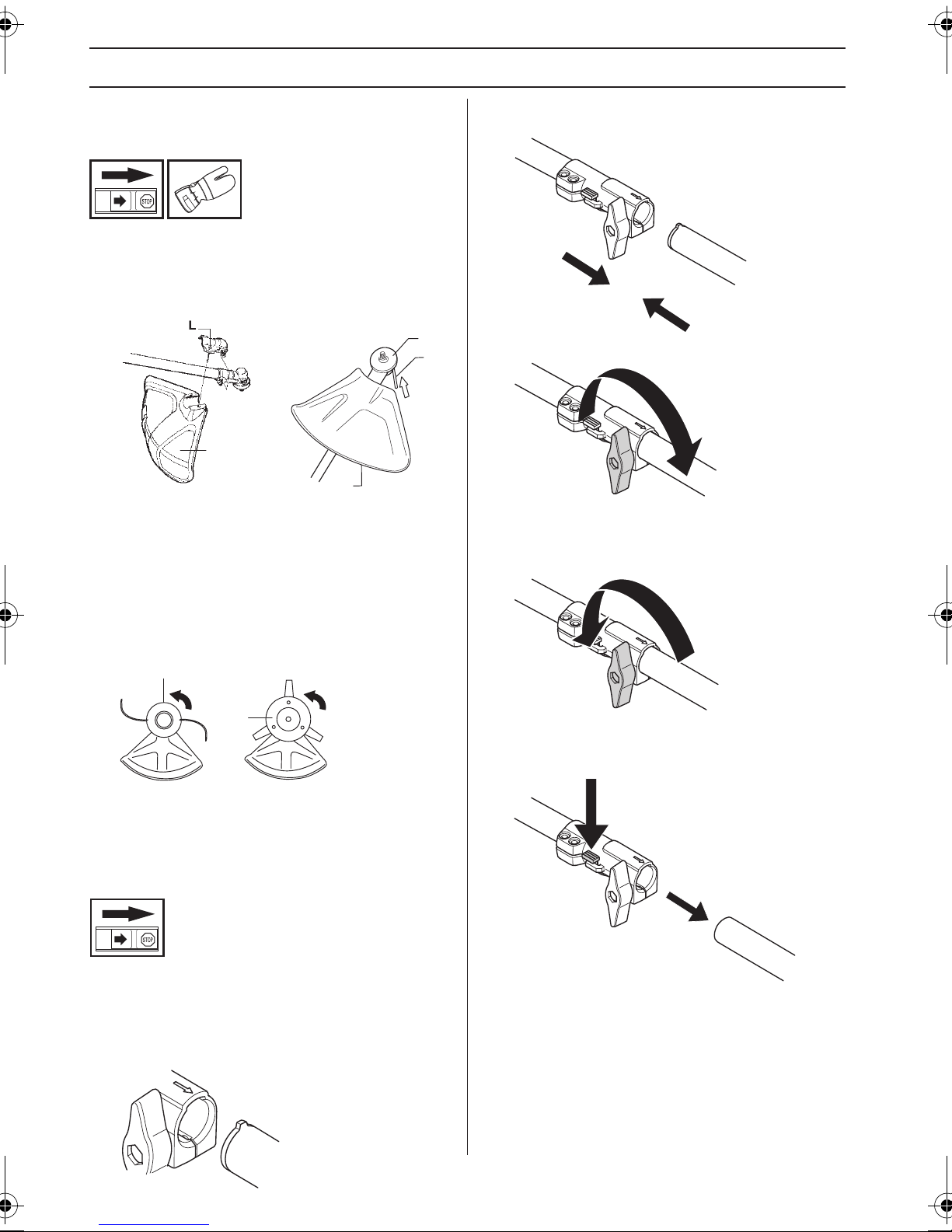
MONTAGE
Montage de la protection de la
tête et de la tête de désherbage
• Monter le carter de protection (A) destiné au travail
avec la tête de désherbage. Emboîter le carter de
protection/la protection combinée dans la fixation du
tube de transmission et fixer à l’aide d’une vis (L).
B
C
A
A
• Monter un toc d’entraînement (B) sur l’axe sortant.
• Faire tourner l’axe de la lame jusqu’à ce que l’un des
trous du toc d’entraînement coïncide avec le trou
correspondant du carter.
• Insérer la goupille d’arrêt (C) dans le trou afin de
bloquer l’axe.
• Visser la tête de désherbage/les couteaux en
plastique (H) dans le sens contraire de la rotation.
H
• Pousser la fixation dans le raccord jusqu’à ce qu’un
déclic indique qu’elle est bien en place.
• Serrer fortement la manette avant d’utiliser l’unité.
Démontage
• Desserrer le raccord en tournant la manette (au moins
3 fois).
H
• Le démontage s’effectue dans l’ordre inverse.
Montage et démontage d’un tube
de transmission démontable
(GC2225C)
Montage
• Desserrer le raccord en tournant la manette.
• Aligner la languette de la fixation (A) sur la flèche du
raccord (B).
B
A
Appuyez sur le bouton (C) et le maintenir enfoncé. Tout en
maintenant solidement l’extrémité du moteur, tirer la
fixation hors du raccord.
C
38 – French
Page 39

MONTAGE
Montage du protège-lame, de la
lame à herbe et du couteau à
herbe
G
F
E
D
A
• Emboîter le protège-lame/la protection combinée (A)
dans la fixation du tube de transmission et fixer à
l’aide d’une vis.
REMARQUE! Utiliser le protège-lame recommandé. Voir
le chapitre Caractéristiques techniques.
• Monter un toc d’entraînement (B) sur l’axe sortant.
• Faire tourner l’axe de la lame jusqu’à ce que l’un des
trous du toc d’entraînement coïncide avec le trou
correspondant du carter.
• Insérer la goupille d’arrêt (C) dans le trou afin de
bloquer l’axe.
• Placer la lame (D), le bol de garde au sol (E) et la
bride de support (F) sur l’axe sortant.
• Monter l’écrou (G). Serrer l’écrou au couple de
serrage de 35-50 Nm (3,5-5 kpm). Utiliser la clé à
douille du jeu d’outils. Tenir le manche de la clé le plus
près possible du protège-lame. Serrer l’écrou en
tournant la clé dans le sens de rotation (NB! filetage à
gauche).
B
C
French – 39
Page 40

MANIPULATION DU CARBURANT
Sécurité carburant
Ne jamais démarrer la machine:
1 Si du carburant a été renversé. Essuyer
soigneusement toute trace et laisser les restes
d’essence s’évaporer.
2 Si vous avez renversé du carburant sur vous ou sur
vos vêtements, changez de vêtements. Lavez les
parties du corps qui ont été en contact avec le
carburant. Utilisez de l’eau et du savon.
3 S’il y a fuite de carburant. Vérifier régulièrement que
le bouchon du réservoir et la conduite de carburant ne
fuient pas.
Transport et rangement
• Transporter et ranger la machine et le carburant de
façon à éviter que toute fuite ou émanation éventuelle
entre en contact avec une flamme vive ou une
étincelle: machine électrique, moteur électrique,
contact/interrupteur électrique ou chaudière.
• Lors du stockage et du transport de carburant,
toujours utiliser un récipient homologué et conçu à cet
effet.
• Lors des remisages de la machine, vider le réservoir
de carburant. S’informer auprès d’une station-service
comment se débarrasser du carburant résiduel.
• Avant de remiser la machine pour une période
prolongée, veiller à ce qu'elle soit bien nettoyée et que
toutes les mesures d'entretien aient été effectuées.
• Lors du stockage et du transport de la machine,
toujours utiliser la protection de transport de
l’équipement de coupe.
• Sécurisez la machine pendant le transport.
• Afin d'éviter tout démarrage accidentel du moteur,
toujours retirer le chapeau de bougie lors du remisage
prolongé, si la machine n'est pas sous surveillance et
lors de toute mesure de service.
AVERTISSEMENT! Manipuler le
!
carburant avec précaution. Penser aux
risques d’incendie, d’explosion et
d’inhalation.
Carburant
REMARQUE! La machine est équipée d’un moteur deux
temps et doit toujours être alimentée avec un mélange
d'essence et d’huile deux temps. Afin d’obtenir un
mélange approprié, il est important de mesurer avec
précision la quantité d’huile à mélanger. Pour le mélange
de petites quantités de carburant, la moindre erreur peut
sérieusement affecter le rapport du mélange.
AVERTISSEMENT! Le carburant et les
!
vapeurs de carburant sont très
inflammables et peuvent causer des
blessures graves en cas d’inhalation ou
de contact avec la peau. Il convient donc
d’observer la plus grande prudence lors
de la manipulation du carburant et de
veiller à disposer d’une bonne aération.
Essence
REMARQUE! Toujours utiliser une essence de qualité
d’au moins 90 octanes (RON) mélangée avec de l’huile.
Si la machine est équipée d’un pot catalytique (voir
Caractéristiques techniques), n’utiliser que de l’essence
sans plomb de qualité mélangée à de l’huile. Une
essence au plomb détruirait le pot catalytique.
Choisissez de l’essence écologique (alkylat) si vous
pouvez vous en procurer.
Possibilité d’utiliser du carburant mélangé à base
d’éthanol, E10 (la teneur en éthanol ne doit pas dépasser
10 %). L’utilisation de carburants mélangés contenant
plus d’éthanol que l’E10 perturbe le fonctionnement de la
machine et risque d’endommager le moteur.
• Le taux d’octane minimum recommandé est de 90
(RON). Si l’on fait tourner le moteur avec une essence
d’un taux d’octane inférieur à 90, un cognement
risque de se produire, résultant en une augmentation
de la température du moteur pouvant causer de
graves avaries du moteur.
• Si on travaille en permanence à des régimes élevés,
il est conseillé d’utiliser un carburant d’un indice
d’octane supérieur.
Huile deux temps
• Pour obtenir un fonctionnement et des résultats
optimaux, utiliser une huile moteur deux temps
JONSERED fabriquée spécialement pour nos
moteurs deux temps à refroidissement à air.
• Ne jamais utiliser d’huile deux temps pour moteurs
hors-bord refroidis par eau, appelée huile outboard
(désignation TCW).
• Ne jamais utiliser d’huile pour moteurs à quatre
temps.
• Une huile de qualité médiocre ou un mélange huile/
carburant trop riche risquent de mettre en péril le
fonctionnement du pot catalytique et d'en réduire la
durée de vie.
• Rapport de mélange
1:50 (2%) avec huile deux temps JONSERED.
1:33 (3%) avec d’autres huiles conçues pour des
moteurs deux temps à refroidissement par air classés
pour JASO FB/ISO EGB.
Essence,
litres
5 0,10 0,15
10 0,20 0,30
15 0,30 0,45
20 0,40 0,60
Huile deux temps, litres
2% (1:50) 3% (1:33)
40 – French
Page 41

MANIPULATION DU CARBURANT
Mélange
• Toujours effectuer le mélange dans un récipient
propre et destiné à contenir de l’essence.
• Toujours commencer par verser la moitié de l’essence
à mélanger. Verser ensuite la totalité de l’huile.
Mélanger en secouant le récipient. Enfin, verser le
reste de l’essence.
• Mélanger (secouer) soigneusement le mélange avant
de faire le plein du réservoir de la machine.
• Ne jamais préparer plus d’un mois de consommation
de carburant à l’avance.
• Si la machine n’est pas utilisée pendant une longue
période, vidanger et nettoyer le réservoir.
• Si du carburant a été renversé. Essuyer
soigneusement toute trace et laisser les restes
d’essence s’évaporer.
• Utiliser un bidon d’essence comportant un dispositif
d’arrêt de remplissage automatique.
• Nettoyer le pourtour du bouchon de réservoir. Les
impuretés dans le réservoir causent des troubles de
fonctionnement.
• Bien mélanger le carburant en agitant le récipient
avant de remplir le réservoir.
Remplissage de carburant
AVERTISSEMENT! Les mesures de
!
sécurité ci-dessous réduisent le risque
d’incendie:
Mélangez et versez le carburant à
l'extérieur, en l'absence d'étincelles ou
de flammes.
Ne jamais fumer ni placer d’objet chaud à
proximité du carburant.
Ne jamais faire le plein, moteur en
marche.
Arrêter le moteur et le laisser refroidir
pendant quelques minutes avant de faire
le plein.
Ouvrir le bouchon du réservoir lentement
pour laisser baisser la surpression
pouvant régner dans le réservoir.
Serrer soigneusement le bouchon du
réservoir après le remplissage.
Éloignez toujours la machine de la zone
et de la source du plein en carburant
avant de la mettre en marche.
French – 41
Page 42

DÉMARRAGE ET ARRÊT
Contrôles avant la mise en
marche
Contrôler la lame afin de détecter d’éventuelles fissures
au niveau des dents et du trou central. Les raisons les
plus fréquentes de la présence de fissures sont la
formation de coins pointus lors de l’affûtage et l’utilisation
d’une lame aux dents émoussées. Si des fissures sont
constatées, mettre la lame au rebut.
• S’assurer que la bride de support ne présente pas de
fissures par suite d’usure ou de serrage trop fort. En
cas de fissures, mettre la bride de support au rebut.
• Ne jamais utiliser la machine sans protection ou avec
une protection défectueuse.
• Tous les carters doivent être correctement montés et
sans défaut avant le démarrage de la machine.
Démarrage et arrêt
AVERTISSEMENT! Un carter
!
d’embrayage complet avec tube de
transmission doit être monté avant de
démarrer la machine, sinon l’embrayage
risque de lâcher et de provoquer des
blessures.
S’assurer que le contre-écrou n’a pas perdu son pouvoir
bloquant. Le contre écrou doit résister à au moins 1,5 Nm.
Le couple de serrage du contre-écrou doit être de 35-50
Nm.
Contrôler le protège-lame afin de détecter d’éventuels
dommages ou fissures. Remplacer le protège-lame s’il a
subi des dommages ou s’il présente des fissures.
Éloignez toujours la machine de la zone
et de la source du plein en carburant
avant de la mettre en marche. Placer la
machine sur une surface plane.
S’assurer que l’équipement de coupe ne
risque pas de rencontrer un obstacle.
Veiller à ce qu’aucune personne non
autorisée ne se trouve dans la zone de
travail pour éviter le risque de blessures
graves. Distance de sécurité: 15 mètres.
Démarrage
Pompe à carburant: Appuyez sur la pompe à carburant
plusieurs fois jusqu’à ce que le carburant commence à
remplir la poche. Il n’est pas nécessaire de remplir la
poche complètement.
• Contrôler la tête de désherbage et le carter de
protection afin de détecter d’éventuels dommages ou
fissures. Remplacer la tête de désherbage ou le
carter de protection si l’un ou l’autre a subi des
dommages ou présente des fissures.
42 – French
Page 43

DÉMARRAGE ET ARRÊT
Starter: Relevez le starter en position d’étranglement.
AVERTISSEMENT! Lorsque le moteur est
!
Plaquer la machine contre le sol à l’aide de la main
gauche (NOTA! Pas à l’aide du pied!).
Saisissez fermement le blocage de la commande
d’accélération (A) et la commande d’accélération (B) avec
la main gauche, puis tirez rapidement sur le bouton de
démarrage jusqu’à ce que le moteur tente de démarrer,
ou au maximum 5 fois.
démarré avec la commande de starter en
position starter/accélérateur,
l’équipement de coupe commence à
tourner immédiatement.
REMARQUE! Ne pas sortir complètement la corde du
lanceur et ne pas lâcher la poignée avec la corde du
lanceur complètement sortie. Cela pourrait endommager
la machine.
REMARQUE! Ne pas placer aucune partie du corps sur
la surface marqué. Contact peut causer en brûlures à la
peau ou les chocs électriques si le chapeau de bougie est
defecteux. Toujours utiliser des gants. Ne jamais utiliser
une machine dont le chapeau de bougie est defecteux.
A
B
Ne jamais enrouler la corde du lanceur autour de la
main.
Après la tentative de démarrage du moteur ou après avoir
tiré 5 fois sur le fil, abaissez le levier du starter dans la
position de marche.
Saisissez le dispositif de blocage de la commande
d’accélération (A) et la gâchette d’accélération (B), puis
recommencez à tirer sur le fil jusqu’à ce que le moteur
démarre. Assurez-vous que la machine atteigne le plein
régime, puis relâchez la gâchette d’accélération. Dès que
le moteur a démarré, laissez-le tourner pendant
30 secondes avant d’accélérer à fond.
Arrêt
Pour arrêter le moteur, couper l’allumage.
REMARQUE! L'interrupteur d'arrêt se remet
automatiquement en position de démarrage. Toujours
retirer le chapeau de bougie de la bougie lors du
montage, contrôle et/ou entretien, afin d'éviter tout
démarrage accidentel.
French – 43
Page 44

TECHNIQUES DE TRAVAIL
Méthodes de travail
IMPORTANT!
Ce chapitre traite des consignes de sécurité de base lors
du travail avec une débroussailleuse ou un coupe-herbe.
Dans l’éventualité d’une situation rendant la suite du
travail incertaine, consulter un expert. S’adresser au
revendeur ou à l’atelier de réparation.
Évitez les tâches pour lesquelles vous ne vous sentez
pas suffisamment qualifié.
Avant l’utilisation, il est essentiel de comprendre la
différence entre le déblayage forestier, le débroussaillage
et le désherbage.
Les lames à herbe/disques à herbe ne peuvent être
utilisés que lorsque la poignée en J est montée. La lame
de débroussaillage ne doit jamais être utilisée avec la
poignée en J. Lors de l’utilisation de lames à herbe,
munissez-vous du harnais et attachez-le à l’anneau de
suspension.
Règles élémentaires de sécurité
1 Bien observer la zone de travail:
• S’assurer qu’aucune personne, aucun animal ou
aucun autre facteur ne risque de gêner l’utilisateur de
la machine.
• Afin d’éviter que des personnes, des animaux ou
autre n’entrent en contact avec l’équipement de
coupe ou avec des objets lancés par celui-ci.
• REMARQUE! Ne jamais utiliser une machine s’il n’est
pas possible d’appeler au secours en cas d’accident.
2 Inspecter la zone de travail. Retirer tous les objets tels
que les pierres, les morceaux de verre, les clous, les
fils de fer, les bouts de ficelle, etc. pouvant être
projetés ou risquant de bloquer l’équipement de
coupe.
3 Ne pas travailler par mauvais temps: brouillard épais,
pluie diluvienne, vent violent, grand froid, etc.
Travailler par mauvais temps est cause de fatigue et
peut même être dangereux: sol glissant, direction de
chute d’arbre modifiée, etc.
4 S’assurer de pouvoir se tenir et se déplacer en toute
sécurité. Repérer les éventuels obstacles en cas de
déplacement imprévu: souches, pierres, branchages,
fondrières, etc. Observer la plus grande prudence lors
de travail sur des terrains en pente.
5 Soyez bien en équilibre, les pieds d’aplomb.
6 Toujours tenir la machine avec les deux mains. Tenir
la machine du côté droit du corps.
7 L’équipement de coupe doit se trouver sous la taille de
l’utilisateur.
8 Lors des déplacements, arrêter le moteur. Lors des
déplacements longs et des transports, utiliser le
dispositif de protection prévu à cet effet.
9 Ne jamais placer la machine sur le sol avec le moteur
en marche sans pouvoir la surveiller.
AVERTISSEMENT! Ni l’utilisateur de la
!
!
machine, ni qui que ce soit ne doit essayer
de retirer le matériel végétal coupé tant
que le moteur ou l’équipement de coupe
tourne, sous peine de blessures graves.
Arrêter le moteur et l’équipement de
coupe avant de retirer le matériel végétal
qui s'est enroulé autour de l’axe de la
lame, sous peine de blessures. Après
l’utilisation, le renvoi d’angle peut être
chaud pendant un moment. Risque de
brûlures au contact.
AVERTISSEMENT! Attention aux objets
projetés. Toujours utiliser des protections
homologuées pour les yeux. Ne jamais se
pencher au-dessus de la protection de
l'équipement de coupe. Des cailloux,
débris, etc. peuvent être projetés dans les
yeux et causer des blessures très graves,
voire la cécité.
Maintenir à distance toutes les personnes
non concernées par le travail. Les enfants,
les animaux, les spectateurs et les
collègues de travail devront se trouver en
dehors de la zone de sécurité, soit à au
moins 15 mètres. Arrêter immédiatement
la machine si une personne s’approche.
Ne tournez jamais sur vous-même avec la
machine sans vous assurer d’abord que
personne ne se trouve dans la zone de
sécurité.
44 – French
Page 45

TECHNIQUES DE TRAVAIL
Techniques de travail de base
Ramener le moteur au régime de ralenti après chaque
étape de travail. Laisser le moteur tourner à pleins gaz
sans lui faire subir de charge peut endommager
sérieusement le moteur.
AVERTISSEMENT! Il arrive que des
!
!
branches ou de l’herbe se coincent entre
la protection et l’équipement de coupe.
Toujours arrêter le moteur avant de
procéder au nettoyage.
AVERTISSEMENT! Les machines
équipées de lames d’éclaircissage ou de
disques à herbe peuvent être projetées
violemment d’un côté quand la lame
heurte un objet fixe. Ce phénomène est
appelé rebond. Un rebond peut être
suffisamment violent pour projeter la
machine et/ou l’opérateur dans une
direction quelconque et faire perdre le
contrôle de la machine à l’opérateur. Les
rebonds se produisent sans prévenir si
la machine s’accroche sur un objet, cale
ou se bloque. Un rebond est plus apte à
se produire dans des zones où il est
difficile de voir le matériau coupé.
un pas en avant après le mouvement de retour et
reprendre la même position stable.
• Laisser le bol de garde au sol. Son rôle est de
protéger la lame contre tout contact avec le sol.
• Respecter les règles suivantes afin d’éviter que les
matériaux ne s’enroulent autour de la lame:
1Toujours travailler en faisant tourner le moteur à
plein régime.
2Éviter de toucher le matériel végétal coupé au cours
du mouvement de retour.
• Arrêter le moteur, ouvrir le harnais et poser la
machine par terre avant de rassembler le matériel
végétal coupé.
Désherbage avec tête de désherbage
Désherbage
• Maintenir la tête de désherbage juste au-dessus du
sol, l’incliner. Le travail est effectué par l’extrémité du
fil. Laisser le fil travailler à son propre rythme. Ne
jamais forcer le fil dans le matériau à couper.
Eviter d’utiliser la plage 12 h - 15 h de la
lame. Du fait de la vitesse de rotation de
la lame, c’est justement sur cette plage
que l’éjection d’objets risque de se
produire lorsque la lame est appliquée
sur des troncs plus épais.
Débroussaillage avec une lame à herbe
• Ne pas utiliser les lames et les couteaux à herbe pour
les tiges ligneuses.
• La lame à herbe s’utilise pour tous les types d’herbe
haute ou épaisse.
• Faucher l’herbe d’un mouvement de balancier latéral,
le mouvement de droite à gauche constituant la
fauche et le mouvement de gauche le retour. Faire
travailler la lame du côté gauche (secteur 8h à 12 h).
• Si on penche légèrement la lame vers la gauche
pendant le débroussaillage, l’herbe coupée est
disposée en bandes, ce qui facilite le ramassage, par
exemple lors du ratissage.
• Essayer d’adopter un rythme de travail régulier.
Prendre une position stable, les pieds écartés. Faire
• Le fil facilite l’enlèvement d’herbe et de mauvaises
herbes au pied des murs, clôtures, arbres et massifs
fleuris, mais il peut aussi endommager l’écorce des
arbres et des broussailles ainsi que les poteaux des
clôtures.
• Réduire les risques d’endommager la végétation en
limitant la longueur du fil à 10-12 cm et en réduisant le
régime moteur.
Nettoyage par grattage
• La technique du grattage permet d’enlever toute
végétation indésirable. Maintenir la tête de
désherbage juste au-dessus du sol, puis l’incliner.
Laisser l’extrémité du fil battre le sol autour des
arbres, poteaux, statues et similaires. NOTA! Cette
technique accélère l’usure du fil.
• Le fil s’use plus vite et doit être déroulé plus souvent
au contact de cailloux, briques, béton, clôtures
métalliques, etc. qu’au contact d’arbres et de clôtures
en bois.
• Lors du désherbage et du grattage, ne pas faire
tourner le moteur tout à fait à plein régime (80%), ceci
afin que le fil dure plus longtemps et la tête de
désherbage s’use moins.
French – 45
Page 46

TECHNIQUES DE TRAVAIL
Coupe
• Le coupe-herbe est idéal pour atteindre l’herbe aux
endroits difficilement accessibles avec une tondeuse
ordinaire. Maintenir le fil parallèlement au sol lors du
désherbage. Éviter de presser la tête de désherbage
contre le sol, puisque cela risque d’endommager la
pelouse et le matériel.
• Éviter de maintenir la tête de désherbage
constamment au contact avec le sol en utilisation
normale. Un contact permanent peut endommager la
tête de désherbage et accélérer son usure.
Balayage
• L’effet soufflant du fil rotatif peut être utilisé pour un
nettoyage simple et rapide. Maintenir le fil parallèle et
au-dessus des surfaces à balayer, puis balader l’outil
suivant un mouvement de balancier.
• Lors de la coupe et du balayage, faire tourner à plein
régime afin d’obtenir un bon résultat.
IMPORTANT!
Pour éviter les déséquilibres et les vibrations au niveau
des poignées, le couvercle de la tête de désherbage doit
être nettoyé à chaque fois que le fil est réalimenté.
Vérifiez également si le reste de la tête doit être nettoyé.
46 – French
Page 47

ENTRETIEN
Carburateur
Les caractéristiques techniques de cette machine
Jonsered assurent des émissions de gaz nocifs réduites
au minimum. Le moteur est considéré rodé après 8-10
pleins. Pour s’assurer que le moteur fonctionne
correctement et libère peu de gaz d’échappement après
la période de rodage, demander au revendeur/à l’atelier
de réparation (disposant d’un compte-tours) de régler le
carburateur.
Réglage de base
• Le réglage de base du carburateur est effectué à
l’usine. Le réglage de base est plus riche que le
mélange optimal et doit être maintenu pendant les
premières heures de service de la machine. Ensuite,
il faut effectuer un réglage fin du carburateur. Le
réglage fin doit être effectué par une personne
qualifiée.
REMARQUE! Si l’équipement de coupe tourne au
ralenti, tourner le pointeau de ralenti T dans le sens
contraire des aiguilles jusqu’à l’arrêt de l’équipement de
coupe.
Réglage du régime de ralenti
Pour tous les réglages, le filtre à air doit être propre et son
couvercle posé.
Régler le régime de ralenti avec le pointeau de ralenti T si
un ajustage est nécessaire. Tourner d’abord le pointeau T
dans le sens des aiguilles jusqu’à ce que l’équipement de
coupe commence à tourner. Tourner ensuite le pointeau
dans le sens inverse jusqu’à l’arrêt de l’équipement de
coupe. Un régime de ralenti correctement réglé permet
au moteur de tourner régulièrement dans toutes les
positions. Il doit également y avoir une bonne marge
avant que l’équipement de coupe se mette à tourner.
T
Régime de ralenti recommandé: Voir le chapitre
Caractéristiques techniques.
AVERTISSEMENT! S’il est impossible de
!
régler le régime de ralenti de manière à
immobiliser l’équipement de coupe,
contacter le revendeur ou l’atelier de
réparation. Ne pas utiliser la machine
tant qu’elle n’est pas correctement
réglée ou réparée.
Système de refroidissement
La machine est équipée d’un système de refroidissement
permettant d’obtenir une température de fonctionnement
aussi basse que possible.
1
2
Le système de refroidissement est composé des
éléments suivants:
1 Contrôler et nettoyer les ouvertures de l’air de
refroidissement.
2 Prise d'air par le carter moteur (à l'intérieur du
réservoir).
Nettoyer le système de refroidissement avec une brosse
une fois par semaine, voire plus souvent dans des
conditions difficiles. Un système de refroidissement sale
ou colmaté provoque la surchauffe de la machine,
endommageant le cylindre et le piston.
Bougie
L’état de la bougie dépend de:
• L’exactitude du réglage du carburateur.
• Mauvais mélange de l’huile dans le carburant (trop
d’huile ou huile inappropriée).
• La propreté du filtre à air.
Ces facteurs peuvent concourir à l’apparition de calamine
sur les électrodes, ce qui à son tour entraîne un mauvais
fonctionnement du moteur et des démarrages difficiles.
French – 47
Page 48

ENTRETIEN
Si la puissance de la machine est trop faible, si la machine
est difficile à mettre en marche ou si le ralenti est
irrégulier, toujours commencer par contrôler l’état de la
bougie avant de prendre d’autres mesures. Si la bougie
est encrassée, la nettoyer et vérifier que l’écartement des
électrodes est de 0,65 mm. Remplacer la bougie une fois
par mois ou plus souvent si nécessaire.
0,65
REMARQUE! Toujours utiliser le type de bougie
recommandé! Une bougie incorrecte peut endommager
le piston/le cylindre. S’assurer que la bougie est dotée
d’un antiparasites.
Tube de transmission démontable
(GC2225C)
L’extrémité de l’arbre d’entraînement dans le tube
inférieur doit être lubrifiée intérieurement avec de la
graisse toutes les 30 heures d’utilisation. A défaut de
graissage régulier, les extrémités de l’arbre
d’entraînement sur les modèles démontables (raccords
cannelés) risqueraient de gripper.
Nettoyer le filtre après 25 heures de service, ou plus
souvent si les conditions de travail sont
exceptionnellement poussiéreuses.
Nettoyage du filtre à air
Relevez le starter pour fermer sa soup
Déposer le capot de filtre et retirer le filtre. Nettoyer le filtre
avec de l’eau chaude savonneuse. Nettoyez aussi
l'intérieur du couvercle du filtre avec de l'air ou une
brosse. S’assurer que le filtre est sec avant de le
remonter.
Un filtre ayant servi longtemps ne peut plus être
complètement nettoyé. Le filtre à air doit donc être
remplacé à intervalles réguliers. Tout filtre endommagé
doit être remplacé immédiatement. Tout filtre à air
endommagé, très sale ou imbibé d'essence doit être
remplacé.
Filtre à air
Le filtre à air doit être maintenu propre pour éviter:
• Un mauvais fonctionnement du carburateur
• Des problèmes de démarrage
• Une perte de puissance
• Une usure prématurée des éléments du moteur.
• Une consommation anormalement élevée de
carburant
48 – French
Renvoi d’angle
Le renvoi d’angle est enduit en usine de la quantité de
graisse nécessaire. Toutefois, avant d’utiliser la machine,
il convient de s’assurer que le renvoi d’angle est au 3/4
rempli de graisse. Utiliser une graisse JONSERED
spéciale.
En général, il n’est pas nécessaire de remplacer le
lubrifiant du carter, sauf en cas de réparations.
Page 49

ENTRETIEN
Schéma d’entretien
La liste ci-dessous indique l’entretien à effectuer sur la machine. La plupart des points sont décrits à la section Entretien.
L’utilisateur ne peut effectuer que les travaux d’entretien et de révision décrits dans ce manuel d’utilisation. Les mesures
plus importantes doivent être effectuées dans un atelier d’entretien agréé.
Entretien
Nettoyer l’extérieur de la machine. X
Contrôler le bon fonctionnement du verrou d’accélérateur et de
l’accélérateur
Contrôler le bon fonctionnement du contacteur d’arrêt. X
S’assurer que l’équipement de coupe ne tourne pas lorsque le
moteur tourne au ralenti.
Nettoyer le filtre à air. Le remplacer si nécessaire. X
S’assurer que la protection est intacte et qu’elle ne présente pas
de fissures. Remplacer la protection si elle a subi des coups ou
si elle présente des fissures.
S’assurer que la tête de désherbage est intacte et qu’elle n’est
pas fissurée. Au besoin, remplacer la tête de désherbage.
S’assurer que toutes les vis et tous les écrous sont bien serrés. X
Vérifier qu’il n’y a pas de fuite de carburant du moteur, du
réservoir ou des conduits de carburant.
Nettoyer le système de refroidissement de la machine. X
Contrôler le démarreur et son lanceur. X
S’assurer que les amortisseurs ne sont pas endommagés. X
Nettoyer la bougie d’allumage extérieurement. Déposer la
bougie et vérifier la distance entre les électrodes. Au besoin,
ajuster la distance de sorte qu’elle soit de 0,65 mm, ou remplacer
la bougie. S’assurer que la bougie est dotée d’un antiparasites.
Nettoyer le carburateur extérieurement, ainsi que l’espace
autour.
Vérifier que le renvoi d’angle est au 3/4 rempli de graisse. Au
besoin, faire un remplissage d’appoint avec une graisse spéciale.
Contrôler que le filtre à carburant n’est pas contaminé ou que le
tuyau de carburant ne comporte pas de fissures ou d’autres
avaries. Remplacer si nécessaire.
Inspecter tous les câbles et connexions. X
Vérifier l’état d’usure de l’embrayage, des ressorts d’embrayage
et du tambour d’embrayage. Faire remplacer si nécessaire dans
un atelier d’entretien agréé.
Remplacer la bougie d’allumage. S’assurer que la bougie est
dotée d’un antiparasites.
Entretien
quotidien
X
X
X
X
X
Entretien
hebdomadaire
X
X
X
Entretien
mensuel
X
X
X
French – 49
Page 50

CARACTÉRISTIQUES TECHNIQUES
Caractéristiques techniques
GC2225 GC2225C
Moteur
Cylindrée, cm
Alésage, mm 34,0 34,0
Course, mm 28 28
Régime de ralenti, tr/min 3000 3000
Régime d'emballement maximal recommandé, tr/min 9500±500 9500±500
Régime de l’axe sortant, tr/min 6500 6500
Puissance moteur maxi selon ISO 8893, kW/ tr/min 1,0/8500 1,0/8500
Silencieux avec pot catalytique Non Non
Système d’allumage réglé en fonction du régime Oui Oui
Système d’allumage
Fabricant/type de système d’allumage IKEDA/UK IKEDA/UK
Bougie NGK BPMR8Y NGK BPMR8Y
Écartement des électrodes, mm 0,65 0,65
Système de graissage/de carburant
Fabricant/type de carburateur Walbro WYA-218 Walbro WYA-218
Contenance du réservoir de carburant, litres 0,65 0,65
Poids
Poids, sans carburant, équipement de coupe et dispositifs de
sécurité, kg
Émissions sonores
(voir rem. 1)
Niveau de puissance sonore mesuré dB(A) 109 109
Niveau de puissance sonore garanti L
Niveaux sonores
(voir remarque 2)
Pression acoustique équivalente au niveau des oreilles de
l’utilisateur, mesurée selon EN/ISO 11806 et ISO 7917, dB(A),
min./max.:
Niveaux de vibrations
(voir remarque 3)
Niveaux de vibrations équivalents (a
des poignées selon EN ISO 11806 et ISO 22867, en m/s
Équipée d'une tête de désherbage (d'origine), gauche/droite 4,4/2,5 4,3/2,6
3
dB(A) 111 111
WA
) mesurés au niveau
hveq
2
25,4 25,4
4,4 4,7
101 101
.
Remarque 1: émission sonore dans l’environnement mesurée comme puissance acoustique (LWA) selon la directive UE
2000/14/CE. Le niveau de puissance sonore reporté pour la machine a été mesuré avec l'équipement de coupe d'origine
qui donne le niveau le plus élevé. Le niveau de puissance sonore garanti diffère du niveau mesuré en cela qu'il prend
également en compte la dispersion et les variations d'une machine à l'autre du même modèle, conformément à la
directive 2000/14/CE.
Remarque 2: Les données reportées pour le niveau de pression sonore équivalent pour la machine montrent une
dispersion statistique typique (déviation standard) de 1 dB (A).
Remarque 3: Les données reportées pour le niveau de vibrations équivalent montrent une dispersion statistique typique
(déviation standard) de 1 m/s
50 – French
2
.
Page 51

CARACTÉRISTIQUES TECHNIQUES
GC2225, GC2225C
Accessoires homologués Type
Filet axe de lame M10
Couteaux en plastique Polytrim 503 93 42-02
Lame/couteau à herbe
Tête de désherbage
GC 2225C
Accessoires homologués N° de réf. Utilisez à
Accessoire de cultivateur avec tige CA 150 537 42 54-02 GC 2225C
Accessoire de taille-haie avec tige HA 110 537 19 66-03 GC 2225C
Accessoire de taille-haie avec tige HA 850 537 19 66-04 GC 2225C
Accessoire de balayeuse avec tige SR600 537 19 67-02 GC 2225C
Supplément pour coupe-herbe avec tube de
transmission TA 850
Accessoire de sciage avec tige PA 1100 537 18 33-24 GC 2225C
Kit de soufflage BAC 952 71 19-21 GC 2225C
Grass 255-4 1" (Ø 255 4 dents) 503 93 42-02
Grass 255-8 (Ø 255 8 dents) 503 93 42-04
Fix 35 503 93 42-04
Tap-N-Go 25 (L) 503 93 42-02
Tap-N-Go 35 / Tap-N-Go 35 Spin 503 93 42-04
Bol de garde au sol Fixe
537 35 35-02 GC 2225C
Protection pour équipement de
coupe, réf.
Déclaration CE de conformité
(Concerne seulement l’Europe)
Nous, Husqvarna AB, SE-561 82 Huskvarna, Suède, tél : +46-36-146500, déclarons que les coupe-herbes Jonsered
GC2225, GC2225C à partir des numéros de série de l’année de fabrication 2013 et ultérieurement (l’année est
clairement indiquée sur la plaque d’identification et suivie d’un numéro de série) sont conformes aux dispositions de la
DIRECTIVE DU CONSEIL :
- du 17 mai 2006 ”directive machines” 2006/42/CE
- du 15 décembre 2004 ”compatibilité électromagnétique” 2004/108/CE.
- du 8 mai 2000 ”émissions sonores dans l’environnement” 2000/14/CE. Estimation de la conformité effectuée selon
l’Annexe V.
Pour des informations sur les émissions sonores, voir le chapitre Caractéristiques techniques.
Les normes harmonisées suivantes ont été appliquées: EN ISO 12100:2010, EN ISO 11806-1:2011, ISO 14982:2009,
CISPR 12:2009
SMP Svensk Maskinprovning AB, Box 7035, SE-750 07 Uppsala, Suède, a procédé à des tests de type facultatifs pour
le compte de Husqvarna AB. Les certificats ont les numéros: SEC/13/2387 - GC 2225, GC 2225C
Huskvarna, le 21 décembre 2013
Per Gustafsson, directeur du développement (Représentant autorisé d’Husqvarna AB et responsable de la
documentation technique.)
French – 51
Page 52

SYMBOLERKLÄRUNG
Symbole
WARNUNG! Freischneider,
Motorsensen und Trimmer können
gefährlich sein! Durch nachlässige
oder falsche Handhabung können
schwere Verletzungen oder tödliche
Unfälle von Anwendern oder anderen Personen
verursacht werden. Es ist überaus wichtig, dass Sie den
Inhalt der Bedienungsanleitung lesen und verstehen.
Lesen Sie die
Bedienungsanweisung sorgfältig
durch und machen Sie sich mit dem
Inhalt vertraut, bevor Sie das Gerät
benutzen.
Benutzen Sie immer:
• Schutzhelm in Bereichen, in denen
Gefahr für von oben herabfallende
Gegenstände besteht
• Einen zugelassenen Gehörschutz
• Zugelassener Augenschutz
Max. Drehzahl der Abtriebswelle,
U/min
10000
Warnung vor hochgeschleuderten
und abprallenden Gegenständen.
Der Anwender des Geräts hat
darauf zu achten, dass während der
Arbeit keine Menschen oder Tiere
15 m
50FT
15
m
5
0
FT
näher als 15 m herankommen.
Maschinen mit Säge- oder
Grasklingen können heftig zur Seite
geschleudert werden, wenn die
Klinge auf einen festen Gegenstand
trifft. Dies wird als Klingenstoß
bezeichnet. Die Klinge kann Arme oder Beine
durchtrennen. Menschen oder Tiere müssen sich stets
mindestens 15 m von der Maschine entfernt aufhalten.
Pfeile, die die Grenzen für die
Platzierung des Handgriffhalters
markieren.
Stets zugelassene
Schutzhandschuhe tragen.
Rutschfeste und stabile Stiefel tragen.
Kraftstoffpumpe
Umweltbelastende
Geräuschemissionen gemäß der
Richtlinie der Europäischen
Gemeinschaft. Die Emission des
Gerätes ist im Kapitel Technische
Daten und auf dem Geräteschild
angegeben.
Sonstige Symbole/Aufkleber am Gerät
beziehen sich auf spezielle
Zertifizierungsanforderungen, die in bestimmten
Ländern gelten.
Zum Abstellen des Motors den
Stoppschalter auf Stopp stellen.
ACHTUNG! Der Stoppschalter geht
automatisch in die Startstellung
zurück. Um ein ungewolltes Starten
zu vermeiden, muss bei Montage, Kontrolle und/oder
Wartung daher stets die Zündkappe von der Zündkerze
entfernt werden.
Stets zugelassene
Schutzhandschuhe tragen.
Regelmäßige Reinigung ist
notwendig.
Visuelle Kontrolle.
52 – German
Page 53
INHALT
Inhalt Vor dem Start ist Folgendes zu
SYMBOLERKLÄRUNG
Symbole ............................................................... 52
INHALT
Inhalt ..................................................................... 53
Vor dem Start ist Folgendes zu beachten: ............ 53
EINLEITUNG
Sehr geehrter Kunde! ........................................... 54
WAS IST WAS?
Was ist was? ........................................................ 55
ALLGEMEINE SICHERHEITSVORSCHRIFTEN
Wichtig .................................................................. 56
Persönliche Schutzausrüstung ............................. 56
Sicherheitsausrüstung des Gerätes ..................... 57
Schneidausrüstung ............................................... 60
MONTAGE
Montage des Loophandgriffs ................................ 62
Montage des J-Handgriffs .................................... 62
Montage der Aufhängöse ..................................... 62
Montage der Schneidausrüstung ......................... 62
Montage von Trimmerschutz und Trimmerkopf ..... 63
Montage und Demontage des zerlegbaren
Führungsrohrs ...................................................... 63
Montage von Klingenschutz, Grasklinge und
Grasmesser .......................................................... 64
UMGANG MIT KRAFTSTOFF
Sicherer Umgang mit Kraftstoff ............................ 65
Kraftstoff ............................................................... 65
Tanken .................................................................. 66
STARTEN UND STOPPEN
Kontrolle vor dem Start ......................................... 67
Starten und stoppen ............................................. 67
ARBEITSTECHNIK
Allgemeine Arbeitsvorschriften ............................. 69
WARTUNG
Vergaser ............................................................... 72
Kühlsystem ........................................................... 72
Zündkerze ............................................................. 72
Zerlegbares Führungsrohr .................................. 73
Luftfilter ................................................................. 73
Wartungsschema ................................................. 74
TECHNISCHE DATEN
Technische Daten ................................................. 75
EG-Konformitätserklärung .................................... 76
beachten:
Die Bedienungsanweisung sorgfältig durchlesen.
WARNUNG! Eine längerfristige
!
!
!
Beschallung mit Lärm kann zu
bleibenden Gehörschäden führen. Daher
stets einen zugelassenen Gehörschutz
tragen.
WARNUNG! Unter keinen Umständen
darf die ursprüngliche Konstruktion des
Gerätes ohne Genehmigung des
Herstellers geändert werden. Es ist
immer Originalzubehör zu verwenden.
Unzulässige Änderungen und/oder
unzulässiges Zubehör können zu
schweren oder sogar tödlichen
Verletzungen des Anwenders oder
anderer Personen führen.
WARNUNG! Falsch oder nachlässig
angewendete Freischneider,
Motorsensen oder Trimmer sind
gefährliche Geräte, die schwere
Verletzungen oder tödliche Unfälle von
Anwendern oder anderen Personen
verursachen können. Es ist sehr wichtig,
dass Sie den Inhalt dieser
Bedienungsanweisung lesen und
verstehen.
German – 53
Page 54

EINLEITUNG
Sehr geehrter Kunde!
Herzlichen Glückwunsch zu Ihrem Kauf eines Jonsered-Produkts!
Wir sind überzeugt, dass Sie mit der Qualität und Leistung unserer Produkte über lange Jahre mehr als zufrieden sein
werden. Mit dem Erwerb unserer Produkte erhalten Sie professionelle Hilfe bei Reparaturen und Service, falls doch
einmal etwas passieren sollte. Haben Sie die Maschine nicht bei einem unserer Vertragshändler gekauft, fragen Sie dort
nach der nächsten Servicewerkstatt.
Wir hoffen, dass Sie mit Ihrer Maschine über lange Jahre zufrieden sein werden. Denken Sie daran, diese
Bedienungsanleitung sicher aufzubewahren.Die genaue Befolgung ihres Inhalts (Verwendung, Service, Wartung usw.)
verlängert die Lebensdauer der Maschine erheblich und erhöht zudem ihren Wiederverkaufswert.Sollten Sie Ihre
Maschine verkaufen, händigen Sie dem neuen Besitzer bitte auch die Bedienungsanleitung aus.
Viel Erfolg mit Ihrem neuen Jonsered-Produkt!
Die Jonsered arbeitet ständig an der Weiterentwicklung ihrer Produkte und behält sich daher das Recht auf Änderungen
ohne vorherige Ankündigung, z. B. von Form und Aussehen, vor.
54 – German
Page 55

WAS IST WAS?
10
17
18
24
25
19
4
3
2
1
4
23
26
8
6
29
5
28
27
31
21
11
9
7
30
13
14
16
12
15
20
22
Was ist was?
1 Trimmerkopf
2 Einfüllöffnung für Schmiermittel, winkelgetriebe
3 Winkelgetriebe
4 Schutz für die Schneidausrüstung
5 Führungsrohr
6 Loophandgriff
7 Gashebel
8 Stoppschalter
9 Gashebelsperre
10 Zündkappe und Zündkerze
11 Zylinderdeckel
12 Starthandgriff
13 Kraftstofftank
14 Luftfiltergehäuse
15 Kraftstoffpumpe
16 Choke
17 Gegenmutter
18 Stützflansch
19 Mitnehmer
20 Kombischlüssel
21 Inbusschlüssel
22 Sperrstift
23 Bedienungsanweisung
24 Stützkappe
25 Klinge
26 Führungsrohrverbindung (GC2225C)
27 J-Handgriff
28 Handgriffeinstellung
29 Aufhängöse
30 Gurtsystem
31 Transportschutz
German – 55
Page 56

ALLGEMEINE SICHERHEITSVORSCHRIFTEN
Wichtig Persönliche Schutzausrüstung
WICHTIG!
Das Gerät ist nur für das Trimmen von Gras konstruiert.
Nationale oder regionale Bestimmungen regeln ggf. die
Verwendung. Die festgelegten Bestimmungen erfüllen.
Das einzige Zubehör, für das die Motoreinheit als
Antriebsquelle verwendet werden darf, sind die im Kapitel
Technische Daten empfohlenen Schneidausrüstungen.
Arbeiten Sie niemals mit dem Gerät, wenn Sie müde
sind, Alkohol getrunken oder Medikamente
eingenommen haben, da hierdurch Sehkraft,
Urteilsvermögen oder Körperkontrolle beeinträchtigt
werden können.
Tragen Sie persönliche Schutzausrüstung. Siehe die
Anweisungen unter der Überschrift ”Persönliche
Schutzausrüstung”.
Niemals mit einem Gerät arbeiten, das ohne Zustimmung
des Herstellers modifiziert wurde und nicht länger mit der
Originalausführung übereinstimmt.
Niemals mit einem defekten Gerät arbeiten. Die Kontroll, Wartungs- und Serviceanweisungen in dieser
Bedienungsanweisung sind genau zu befolgen. Gewisse
Wartungs- und Servicemaßnahmen sind von geschulten,
qualifizierten Fachleuten auszuführen. Siehe
Anweisungen unter dem Titel Wartung.
Vor der Inbetriebnahme müssen sämtliche
Abdeckungen, Schutzvorrichtungen und Griffe
angebracht sein. Stellen Sie sicher, dass
Zündkerzenschutz und Zündkabel unversehrt sind, um
die Gefahr von elektrischen Schlägen auszuschließen.
Der Anwender des Geräts hat darauf zu achten, dass
während der Arbeit keine Menschen oder Tiere näher als
15 m an herankommen. Wenn mehrere Anwender am
gleichen Einsatzort tätig sind, muss der
Sicherheitsabstand mindestens 15 Meter betragen.
WICHTIG!
Falsch oder nachlässig angewendete Freischneider,
Motorsensen oder Trimmer sind gefährliche Geräte, die
schwere Verletzungen oder tödliche Unfälle von
Anwendern oder anderen Personen verursachen
können. Es ist sehr wichtig, dass Sie den Inhalt dieser
Bedienungsanweisung lesen und verstehen.
Bei der Benutzung des Gerätes muss die
vorgeschriebene persönliche Schutzausrüstung
angewendet werden. Die persönliche
Schutzausrüstung beseitigt nicht die Unfallgefahr,
begrenzt aber den Umfang der Verletzungen und
Schäden. Bei der Wahl der Schutzausrüstung einen
Fachhändler um Rat fragen.
WARNUNG! Bei Benutzung von
!
HELM
Schutzhelm in Bereichen, in denen Gefahr für von oben
herabfallende Gegenstände besteht
Gehörschützern immer auf Warnsignale
oder Zurufe achten. Den Gehörschutz
immer abnehmen, sobald der Motor
abgestellt ist.
!
!
!
56 – German
WARNUNG! Diese Maschine erzeugt beim
Betrieb ein elektromagnetisches Feld.
Dieses Feld kann sich unter bestimmten
Bedingungen auf die Funktionsweise
aktiver oder passiver medizinischer
Implantate auswirken. Um die Gefahr für
schwere oder tödliche Verletzungen
auszuschließen, sollten Personen mit
einem medizinischen Implantat vor der
Nutzung dieser Maschine ihren Arzt und
den Hersteller des Implantats
konsultieren.
WARNUNG! Einen Motor in einem
geschlossenen oder schlecht belüfteten
Raum laufen zu lassen, kann zum Tod
durch Ersticken oder
Kohlenmonoxidvergiftung führen.
WARNUNG! Niemals Kindern erlauben,
das Gerät zu benutzen oder sich in seiner
Nähe aufzuhalten. Da das Gerät mit einem
rückfedernden Stoppschalter ausgerüstet
ist und mit geringer Geschwindigkeit und
Kraft am Starthandgriff gestartet werden
kann, können u. U. auch kleine Kinder die
Kraft aufbringen, die zum Starten
erforderlich ist. Dies kann zu schweren
Verletzungen führen. Daher ist stets die
Zündkappe zu entfernen, wenn das Gerät
ohne Aufsicht ist.
GEHÖRSCHUTZ
Ein Gehörschutz mit ausreichender Dämmwirkung ist zu
tragen.
AUGENSCHUTZ
Es ist immer ein zugelassener Augenschutz zu tragen.
Bei der Benutzung eines Visiers ist auch eine
zugelassene Schutzbrille zu tragen. Zugelassene
Schutzbrillen sind in diesem Falle diejenigen, die die
Normen ANSI Z87.1 für die USA bzw. EN 166 für EULänder erfüllen.
HANDSCHUHE
Handschuhe sind dann zu tragen, wenn dies notwendig
ist, z. B. bei der Montage der Schneidausrüstung.
Page 57
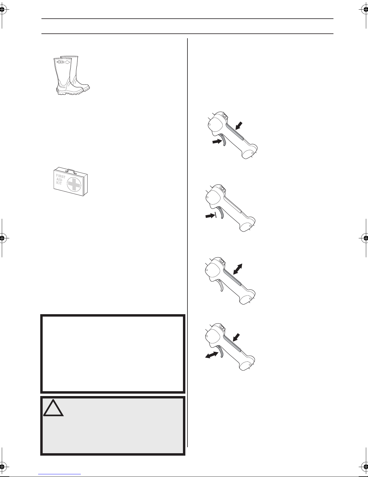
ALLGEMEINE SICHERHEITSVORSCHRIFTEN
STIEFEL
Stiefel mit Stahlkappe und rutschfester Sohle tragen.
KLEIDUNG
Kleidung aus reißfestem Material wählen und nicht zu
weite Kleidungsstücke tragen, die sich leicht im Unterholz
verfangen können. Stets kräftige lange Hosen tragen.
Keinen Schmuck, kurze Hosen oder Sandalen tragen und
nicht barfuß gehen. Schulterlanges Haar nicht offen
tragen.
ERSTE HILFE
Ein Erste-Hilfe-Set soll immer griffbereit sein.
Sicherheitsausrüstung des
Gerätes
Gashebelsperre
Die Gashebelsperre soll die unbeabsichtigte Betätigung
des Gashebels verhindern. Durch Drücken der Sperre (A)
im Handgriff (= wenn man den Handgriff hält) wird der
Gashebel (B) gelöst. Wird der Handgriff losgelassen,
werden Gashebel und Gashebelsperre wieder in ihre
Ausgangsstellung zurückgestellt. Dies geschieht mit Hilfe
von zwei voneinander unabhängigen
Rückzugfedersystemen. In dieser Stellung wird der
Gashebel im Leerlauf automatisch gesichert.
A
B
Kontrollieren, ob der Gashebel in Leerlaufstellung
gesichert ist, wenn sich die Gashebelsperre in
Ausgangsstellung befindet.
In diesem Abschnitt werden einzelnen Teile der
Sicherheitsausrüstung des Gerätes beschrieben, welche
Funktion sie haben und wie ihre Kontrolle und Wartung
ausgeführt werden sollen, um sicherzustellen, dass sie
funktionsfähig sind. (Siehe Kapitel Was ist was? um
herauszufinden, wo die Sicherheitsdetails an Ihrem Gerät
zu finden sind).
Die Lebensdauer der Maschine kann verkürzt werden
und die Unfallgefahr kann steigen, wenn die Wartung der
Maschine nicht ordnungsgemäß und Service und/oder
Reparaturen nicht fachmännisch ausgeführt werden.
Weitere Informationen erteilt Ihnen gerne die nächste
Servicewerkstatt.
WICHTIG!
Service und Reparatur des Gerätes erfordern eine
Spezialausbildung. Dies gilt besonders für die
Sicherheitsausrüstung des Gerätes. Wenn Ihr Gerät den
unten aufgeführten Kontrollanforderungen nicht
entspricht, müssen Sie Ihre Servicewerkstatt aufsuchen.
Beim Kauf eines unserer Produkte wird gewährleistet,
dass Reparatur- oder Servicearbeiten fachmännisch
ausgeführt werden. Sollte der Verkäufer Ihres Gerätes
nicht an unser Fachhändler-Service-Netz angeschlossen
sein, fragen Sie nach unserer nächstgelegenen
Servicewerkstatt.
Die Gashebelsperre eindrücken und kontrollieren, ob sie
in die Ausgangsstellung zurückkehrt, wenn sie
losgelassen wird.
Kontrollieren, ob Gashebel und Gashebelsperre mit dem
dazugehörigen Rückzugfedersystem leicht funktionieren.
WARNUNG! Benutzen Sie nie ein Gerät
!
mit defekter Sicherheitsausrüstung. Die
Sicherheitsausrüstung des Gerätes muss
so kontrolliert und gewartet werden, wie
dies in diesem Abschnitt beschrieben
wird. Wenn Ihr Gerät den
Kontrollanforderungen nicht entspricht,
muss eine Servicewerkstatt aufgesucht
werden.
German – 57
Page 58

ALLGEMEINE SICHERHEITSVORSCHRIFTEN
Siehe die Anweisungen unter der Überschrift Start. Gerät
starten und Vollgas geben. Den Gashebel loslassen und
kontrollieren, ob die Schneidausrüstung völlig zum
Stillstand kommt. Wenn die Schneidausrüstung rotiert,
während sich der Gashebel in Leerlaufstellung befindet,
ist die Leerlaufeinstellung des Vergasers zu kontrollieren.
Siehe die Anweisungen unter der Überschrift Wartung.
Stoppschalter
Mit dem Stoppschalter wird der Motor abgestellt.
Antivibrationssystem
Das Gerät ist mit einem Antivibrationssystem
ausgerüstet, das die Vibrationen wirkungsvoll dämpft und
so für angenehmere Arbeitsbedingungen sorgt.
Wenn der Faden falsch gewickelt ist oder die falsche
Schneidausrüstung benutzt wird, verstärken sich die
Vibrationen. Siehe die Anweisungen unter der Überschrift
Schneidausrüstung.
Das Antivibrationssystem der Maschine reduziert die
Vibrationsübertragung zwischen Motor- und
Welleneinheit der Maschine.
Den Motor starten und kontrollieren, ob der Motor stoppt,
wenn der Stoppschalter in Stoppstellung geführt wird.
Schutz für die Schneidausrüstung
Dieser Schutz soll verhindern, dass lose Gegenstände
zum Anwender hochgeschleudert werden. Der Schutz
verhindert auch, dass der Anwender mit der
Schneidausrüstung in Berührung kommt.
Den Schutz auf Schäden und Risse kontrollieren. Den
Schutz austauschen, wenn er Schlägen ausgesetzt war
oder Risse aufweist.
Immer den empfohlenen Schutz für die jeweilige
Schneidausrüstung verwenden. Siehe das Kapitel
Technische Daten.
WARNUNG! Unter keinen Umständen darf
!
eine Schneidausrüstung ohne einen
zugelassenen Schutz betrieben werden.
Siehe das Kapitel Technische Daten. Wenn
ein falscher oder ein defekter Schutz
montiert wird, können dadurch schwere
Verletzungen verursacht werden.
Die Antivibrationselemente regelmäßig auf Risse und
Verformungen überprüfen. Kontrollieren, ob die
Vibrationsdämpfer unbeschädigt und fest verankert sind.
WARNUNG! Personen mit
!
Kreislaufstörungen, die zu oft
Vibrationen ausgesetzt werden, laufen
Gefahr, Schäden an den Blutgefäßen
oder am Nervensystem davonzutragen.
Gehen Sie zum Arzt, wenn Sie an Ihrem
Körper Symptome feststellen, die auf
Vibrationsschäden deuten. Beispiele
solcher Symptome sind: Einschlafen von
Körperteilen, Gefühlsverlust, Kitzeln,
Stechen, Schmerz, Verlust oder
Beeinträchtigung der normalen
Körperkraft, Veränderungen der
Hautfarbe oder der Haut. Diese
Symptome treten am häufigsten in den
Fingern, Händen oder Handgelenken auf.
58 – German
Page 59

ALLGEMEINE SICHERHEITSVORSCHRIFTEN
Schalldämpfer
Der Schalldämpfer soll den Geräuschpegel so weit wie
möglich senken und die Abgase des Motors vom
Anwender fernhalten.
Für Schalldämpfer ist es sehr wichtig, dass die Kontroll-,
Wartungs- und Serviceanweisungen befolgt werden.
Niemals ein Gerät mit defektem Schalldämpfer benutzen.
Regelmäßig kontrollieren, ob der Schalldämpfer fest am
Gerät montiert ist.
Gegenmutter
Bestimmte Schneidausrüstungen sind mit einer
Gegenmutter gesichert.
Bei der Montage die Mutter entgegen der
Rotationsrichtung der Schneidausrüstung anziehen. Bei
der Demontage die Mutter in der Rotationsrichtung der
Schneidausrüstung lösen. (ACHTUNG! Die Mutter hat ein
Linksgewinde.)
Beim Lösen und Anziehen der Sägeklingenmutter
besteht die Gefahr, dass man sich an den Zähnen der
Sägeklinge verletzt. Daher darauf achten, dass die Hand
bei dieser Arbeit durch den Klingenschutz geschützt ist.
Immer einen Hülsenschlüssel mit ausreichend langem
Schaft verwenden, damit dies möglich ist. Der Pfeil in der
Abbildung zeigt, in welchem Bereich der Hülsenschlüssel
beim Lösen bzw. Anziehen der Mutter arbeiten soll.
WARNUNG! Der Schalldämpfer enthält
!
Chemikalien, die karzinogen sein
können. Falls der Schalldämpfer
beschädigt wird, vermeiden Sie es, mit
diesen Stoffen in Berührung zu kommen.
WARNUNG! Denken Sie daran:
!
Die Motorabgase sind heiß und können
Funken enthalten, die einen Brand
verursachen können. Aus diesem
Grunde sollte das Gerät niemals im
Innenbereich oder in der Nähe von
feuergefährlichen Stoffen gestartet
werden!
Die Nylonsicherung der Mutter darf nicht so abgenutzt
sein, dass sie sich von Hand schrauben lässt. Die
Sicherung soll mindestens 1,5 Nm halten. Nachdem sie
ca. 10 Mal aufgeschraubt worden ist, ist die Mutter
auszutauschen.
German – 59
Page 60

ALLGEMEINE SICHERHEITSVORSCHRIFTEN
Schneidausrüstung
Dieser Abschnitt beschreibt, wie man durch
vorschriftsmäßige Wartung und Anwendung der richtigen
Schneidausrüstung:
• Verringert die Rückschlagneigung des Gerätes.
• Erreicht eine maximale Schneidleistung.
• Verlängert die Lebensdauer der Schneidausrüstung.
WICHTIG!
Die Schneidausrüstung immer nur mit dem von uns
empfohlenen Schutz verwenden! Siehe Kapitel
Technische Daten.
Zum korrekten Einlegen des Fadens und zur Wahl des
richtigen Fadendurchmessers siehe die Anweisungen
für die Schneidausrüstung.
Die Schneidzähne der Klinge sollen stets korrekt und
gut geschärft sein! Befolgen Sie unsere Empfehlungen.
Beachten Sie auch die Anweisungen auf der
Klingenverpackung.
WARNUNG! Den Motor immer abstellen,
!
bevor irgendwelche Arbeiten an der
Schneidausrüstung ausgeführt werden.
Diese rotiert noch weiter, nachdem der
Gashebel losgelassen wurde.
Kontrollieren, ob die Schneidausrüstung
völlig stillsteht, und das Kabel von der
Zündkerze abziehen, bevor mit der Arbeit
an der Schneidausrüstung begonnen
wird.
Grundregeln
Die Schneidausrüstung immer nur mit dem von uns
empfohlenen Schutz verwenden! Siehe Kapitel
Technische Daten.
Die Schneidzähne der Klinge sollen stets korrekt und gut
geschärft sein! Befolgen Sie unsere Anleitung und
verwenden Sie die empfohlene Schärflehre. Eine falsch
geschärfte oder beschädigte Klinge erhöht die
Unfallgefahr.
Die Schneidausrüstung auf Beschädigung und Risse
kontrollieren. Beschädigte Schneidausrüstungen sind
grundsätzlich auszutauschen.
WARNUNG! Durch eine falsche
!
Schneidausrüstung oder eine falsch
gefeilte Klinge erhöht sich die
Rückschlaggefahr.
Schneidausrüstung
Grasklinge und Grasmesser sind für das Mähen von
dichtem hohen Gras vorgesehen.
Der Trimmerkopf dient zum Rasentrimmen.
Feilen von Grasmesser und Grasklinge
• Befolgen Sie die Feilanleitung auf der Verpackung der
Schneidausrüstung. Klinge und Messer werden mit
einer einhiebigen Flachfeile gefeilt.
• Alle Schneiden gleichmäßig feilen, damit keine
Unwucht entsteht.
WARNUNG! Eine Klinge, die verbogen,
!
schief, gerissen, gebrochen oder auf
andere Art beschädigt ist, immer
aussortieren. Niemals versuchen, eine
schiefe Klinge zur weiteren Anwendung
wieder zu richten. Ausschließlich
Originalklingen des vorgeschriebenen
Typs verwenden.
60 – German
Page 61

ALLGEMEINE SICHERHEITSVORSCHRIFTEN
Trimmerkopf
WICHTIG!
Stets darauf achten, dass der Trimmerfaden fest und
gleichmäßig auf die Rolle gewickelt wird, andernfalls
entstehen im Gerät gesundheitsschädliche Vibrationen.
• Nur die empfohlenen Trimmerköpfe und Fäden
verwenden. Sie sind vom Hersteller für eine
bestimmte Motorgröße getestet worden. Dies ist
besonders wichtig, wenn ein vollautomatischer
Trimmerkopf verwendet wird. Benutzen Sie nur die
empfohlene Schneidausrüstung. Siehe das Kapitel
Technische Daten.
• Im Allgemeinen erfordert ein kleineres Gerät kleine
Trimmerköpfe und umgekehrt. Der Grund hierfür ist,
dass der Motor beim Mähen mit Faden diesen radial
vom Trimmerkopf herausschleudern und dabei auch
den Widerstand des zu mähenden Grases
überwinden muss.
• Die Länge des Fadens ist ebenfalls wichtig. Beim
gleichen Fadendurchmesser erfordert ein längerer
Faden eine größere Motorleistung als ein kurzer.
• Darauf achten, dass das Messer am Trimmerschutz
intakt ist. Es dient dazu, den Faden auf die richtige
Länge zu schneiden.
• Die Lebensdauer des Fadens lässt sich verlängern,
indem man ihn für ein paar Tage in Wasser legt.
Dadurch wird der Faden steifer und hält länger.
German – 61
Page 62

MONTAGE
Montage des Loophandgriffs
• Den Loophandgriff auf das Führungsrohr klemmen.
Bitte beachten, dass der Loophandgriff zwischen den
Pfeilmarkierungen am Führungsrohr montiert werden
muss.
• Den Abstandhalter in die Führung im Loophandgriff
schieben. Mutter, Drehknopf und Schraube
montieren. Nicht zu fest anziehen.
• Nun eine Feineinstellung vornehmen, so dass sich mit
dem Trimmer eine bequeme Arbeitshaltung ergibt.
Dann die Schraube.
Montage der Aufhängöse
Die Aufhängöse wird zwischen hinterem Handgriff und
Loophandgriff montiert. Die Öse so plazieren, daß das
Gerät gut ausbalanciert ist und sich eine bequeme
Arbeitshaltung ergibt.
Befestigen Sie bei Verwendung von Grasklingen den
Schultergurt an der Aufhängöse.
Montage der Schneidausrüstung
WARNUNG!
!
Bei der Montage der Schneidausrüstung
ist es äußerst wichtig, dass die Führung
des Mitnehmers/Stützflansches korrekt
im Zentrumloch der Schneidausrüstung
sitzt. Eine falsch montierte
Schneidausrüstung kann schwere oder
gar lebensgefährliche Verletzungen
verursachen.
Montage des J-Handgriffs
WARNUNG! Wenn der J-Handgriff
!
Den J-Handgriff gem. Abbildung mit drei Schrauben am
Loophandgriff montieren.
Nun eine Feineinstellung vornehmen, sodass sich eine
bequeme Arbeitsstellung ergibt. Die Schrauben
anziehen.
montiert ist, dürfen nur Grasklingen/
Grasmesser oder Trimmerköpfe/
Kunststoffmesser verwendet werden.
Zusammen mit dem J-Handgriff niemals
eine Sägeklinge verwenden.
WARNUNG! Unter keinen Umständen
!
darf eine Schneidausrüstung ohne einen
zugelassenen Schutz betrieben werden.
Siehe das Kapitel Technische Daten.
Wenn ein falscher oder ein defekter
Schutz montiert wird, können dadurch
schwere Verletzungen verursacht
werden.
62 – German
Page 63

MONTAGE
Montage von Trimmerschutz und
Trimmerkopf
• Für die Arbeit mit dem Trimmerkopf den
Trimmerschutz (A) montieren. Den Trimmerschutz/
Kombischutz an der Halterung am Führungsrohr
einhaken und mit einer Schraube (L) fixieren.
B
C
A
A
• Mitnehmer (B) an der Abtriebswelle montieren.
• Die Klingenachse drehen, bis sich eines der Löcher
des Mitnehmers mit dem entsprechenden Loch im
Getriebegehäuse deckt.
• Den Sperrstift (C) in das Loch stecken, so dass die
Achse fixiert ist.
• Den Trimmerkopf/die Kunststoffmesser (H) entgegen
der Rotationsrichtung aufschrauben.
H
• Drücken Sie das Ansatzstück bis zum Einrasten in die
Kupplung.
• Ziehen Sie den Knauf fest an, bevor Sie die Einheit
verwenden.
Demontage
• Lösen Sie die Kupplung, indem Sie den Knauf
(mindestens dreimal) drehen.
H
• Die Demontage erfolgt in umgekehrter Reihenfolge.
Montage und Demontage des
zerlegbaren Führungsrohrs
(GC2225C)
Montage
• Lösen Sie die Kupplung, indem Sie den Knauf
drehen.
• Richten Sie den Vorsprung am Ansatzstück (A) mit
dem Pfeil an der Kupplung (B) aus.
B
A
Halten Sie die Taste (C) gedrückt. Halten Sie das
Motorende sicher fest und ziehen Sie das Ansatzstück
gerade aus der Kupplung heraus.
C
German – 63
Page 64

MONTAGE
Montage von Klingenschutz,
Grasklinge und Grasmesser
G
F
E
D
A
B
C
• Die Mutter (G) montieren. Die Mutter ist mit einem
Moment von 35-50 Nm (3,5-5 kpm) anzuziehen. Den
Hülsenschlüssel aus dem Werkzeugsatz verwenden.
Den Schaft des Schlüssels so nah wie möglich am
Klingenschutz greifen. Die Mutter wird angezogen,
wenn der Schlüssel entgegen der Rotationsrichtung
geführt wird (Achtung: Linksgewinde).
• Den Klingenschutz/Kombischutz (A) an seiner
Halterung am Führungsrohr einhaken und mit einer
Schraube fixieren.
ACHTUNG! Den empfohlenen Klingenschutz
verwenden. Siehe das Kapitel Technische Daten.
• Mitnehmer (B) an der Abtriebswelle montieren.
• Die Klingenachse drehen, bis sich eines der Löcher
des Mitnehmers mit dem entsprechenden Loch im
Getriebegehäuse deckt.
• Den Sperrstift (C) in das Loch stecken, so dass die
Achse fixiert ist.
• Klinge (D), Stützkappe (E) und Stützflansch (F) an der
Abtriebswelle montieren.
64 – German
Page 65
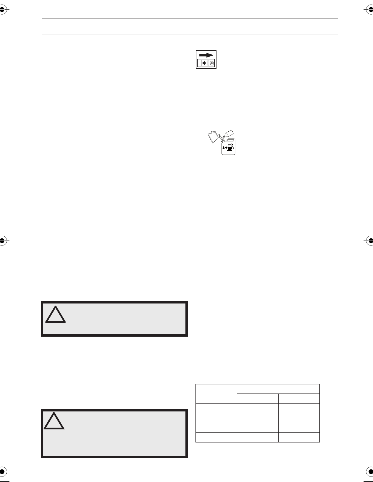
UMGANG MIT KRAFTSTOFF
Sicherer Umgang mit Kraftstoff
Das Gerät niemals starten, wenn:
1 Wenn Kraftstoff darüber verschüttet wurde. Alles
abwischen und restliches Benzin verdunsten lassen.
2 Wenn Sie Kraftstoff über sich selbst oder Ihre
Kleidung verschüttet haben, ziehen Sie sich um.
Waschen Sie die Körperteile, die mit dem Kraftstoff in
Berührung gekommen sind. Wasser und Seife
verwenden.
3 Wenn es Kraftstoff leckt. Tankdeckel und
Tankleitungen regelmäßig auf Undichtigkeiten
überprüfen.
Transport und Aufbewahrung
• Das Gerät und den Kraftstoff so transportieren und
aufbewahren, dass bei eventuellen Undichtigkeiten
entweichende Dämpfe oder Kraftstoff nicht mit
Funken oder offenem Feuer in Kontakt kommen
können, z. B. von Elektrogeräten, Elektromotoren,
elektrischen Kontakten/Schaltern oder Heizkesseln.
• Zum Transport und zur Aufbewahrung von Kraftstoff
sind speziell für diesen Zweck vorgesehene und
zugelassene Behälter zu verwenden.
• Bei längerer Aufbewahrung des Geräts ist der
Kraftstofftank zu leeren. An der nächsten Tankstelle
können Sie erfahren, wie Sie überschüssigen
Kraftstoff am besten entsorgen.
• Vor der Langzeitaufbewahrung sicherstellen, dass die
Maschine gründlich gesäubert und komplett gewartet
wurde.
• Bei Transport oder Aufbewahrung des Gerätes muss
der Transportschutz für die Schneidausrüstung immer
montiert sein.
• Sichern Sie die Maschine während des Transports.
• Um ein ungewolltes Starten des Motors zu
vermeiden, ist die Zündkappe bei der
Langzeitaufbewahrung und bei allen
Servicemaßnahmen zu entfernen, sowie wenn das
Gerät ohne Aufsicht ist.
WARNUNG! Beim Umgang mit Kraftstoff
!
vorsichtig sein. Denken Sie an das
Feuer- und Explosionsrisiko und an die
Gefahr des Einatmens.
Kraftstoff
ACHTUNG! Das Gerät ist mit einem Zweitaktmotor
ausgestattet und daher ausschließlich mit einer Mischung
aus Benzin und Zweitaktöl zu betreiben. Damit das
Mischungsverhältnis richtig ist, muss die beizumischende
Ölmenge unbedingt genau abgemessen werden. Wenn
kleine Kraftstoffmengen gemischt werden, wirken sich
auch kleine Abweichungen bei der Ölmenge stark auf das
Mischungsverhältnis aus.
WARNUNG! Kraftstoff und
!
Kraftstoffdämpfe sind sehr
feuergefährlich und können beim
Einatmen und auf der Haut schwere
Schäden verursachen.Beim Umgang mit
Kraftstoff ist daher Vorsicht geboten und
für eine gute Belüftung zu sorgen.
Benzin
ACHTUNG! Stets Qualitätsbenzin mit Ölbeimischung mit
mind. 90 Oktan (ROZ) verwenden. Wenn Ihr Gerät mit
Katalysator ausgestattet ist (siehe Kapitel Technische
Daten), muss stets bleifreies Qualitätsbenzin mit
Ölbeimischung verwendet werden. Verbleites Benzin
zerstört den Katalysator.
Wenn umweltgerechtes sog. Alkylatbenzin zur Verfügung
steht, ist dieses zu verwenden.
Ethanol-Kraftstoffgemisch, E10 kann verwendet werden
(max. 10 %ige Ethanol-Mischung). Die Verwendung von
Ethanol-Mischungen höher als E10 führt zu Magerlauf,
der Motorschäden verursachen kann.
• Als niedrigste Oktanzahl wird ROZ 90 empfohlen.
Wenn der Motor mit Benzin einer niedrigeren
Oktanzahl als 90 betrieben wird, läuft er nicht
einwandfrei. Das führt zu erhöhten
Motortemperaturen, die schwere Motorschäden
verursachen können.
• Wenn kontinuierlich bei hohen Drehzahlen gearbeitet
wird, ist eine höhere Oktanzahl zu empfehlen.
Zweitaktöl
• Das beste Resultat und die beste Leistung wird mit
JONSERED-Zweitaktmotoröl erzielt, das speziell für
unsere luftgekühlten Zweitaktmotoren hergestellt
wird.
• Niemals Zweitaktöl für wassergekühlte
Außenbordmotoren, sog.Outboardoil (TCW),
verwenden.
• Niemals Öl für Viertaktmotoren verwenden.
• Eine unzureichende Ölqualität oder ein zu fettes Öl/
Kraftstoff-Gemisch kann die Funktion des
Katalysators beeinträchtigen und seine Lebensdauer
reduzieren.
• Mischungsverhältnis
1:50 (2 %) mit JONSERED-Zweitaktöl.
1:33 (3 %) mit anderen Ölen für luftgekühlte
Zweitaktmotoren der Klasse JASO FB/ISO EGB.
Benzin, Liter
5 0,10 0,15
10 0,20 0,30
15 0,30 0,45
20 0,40 0,60
Zweitaktöl, Liter
2% (1:50) 3% (1:33)
German – 65
Page 66

UMGANG MIT KRAFTSTOFF
Mischen
• Benzin und Öl stets in einem sauberen, für Benzin
zugelassenen Behälter mischen.
• Immer zuerst die Hälfte des Benzins, das gemischt
werden soll, einfüllen. Danach die gesamte Ölmenge
einfüllen. Die Kraftstoffmischung mischen (schütteln).
Dann den Rest des Benzins dazugeben.
• Vor dem Einfüllen in den Tank der Maschine die
Kraftstoffmischung noch einmal sorgfältig mischen
(schütteln).
• Kraftstoff höchstens für einen Monat im Voraus
mischen.
• Wenn das Gerät über einen längeren Zeitraum nicht
benutzt wird, den Kraftstofftank entleeren und
reinigen.
• Verwenden Sie einen Kraftstoffbehälter mit
Überfüllungsschutz.
• Um den Tankdeckel herum sauberwischen.
Verunreinigungen im Tank verursachen
Betriebsstörungen.
• Vor dem Einfüllen in den Tank den Behälter noch
einmal schütteln, damit der Kraftstoff gut gemischt ist.
Tanken
!
WARNUNG! Folgende
Vorsichtsmaßnahmen verringern die
Feuergefahr:
Den Kraftstoff draußen in Abwesenheit
von Funken und Flammen mischen und
eingießen.
Beim Tanken nicht rauchen und jegliche
Wärmequellen vom Kraftstoff fernhalten.
Niemals bei laufendem Motor tanken.
Den Motor abstellen und vor dem Tanken
einige Minuten abkühlen lassen.
Den Tankdeckel stets vorsichtig öffnen,
so dass sich ein evtl. vorhandener
Überdruck langsam abbauen kann.
Den Tankdeckel nach dem Tanken wieder
sorgfältig zudrehen.
Die Maschine vor dem Start immer aus
dem Auftankbereich und von der
Auftankquelle weg bewegen.
• Wenn Kraftstoff darüber verschüttet wurde. Alles
abwischen und restliches Benzin verdunsten lassen.
66 – German
Page 67

STARTEN UND STOPPEN
Kontrolle vor dem Start
Die Klinge auf Risse am Zahnansatz und um das
Mittelloch herum kontrollieren. Die häufigste Ursache für
Rissbildungen am Zahnansatz stellen beim Feilen
entstandene scharfe Ecken oder die Anwendung der
Klinge in stumpfem Zustand dar. Die Klinge austauschen,
wenn sie Risse aufweist.
• Das Gerät niemals ohne Schutz oder mit defektem
Schutz benutzen.
• Vor dem Start des Geräts müssen sämtliche Gehäuse
korrekt montiert und in einwandfreiem Zustand sein.
Starten und stoppen
• Den Stützflansch auf Risse hin untersuchen, die
aufgrund von Materialermüdung oder zu festem
Anziehen entstehen können. Den Stützflansch
austauschen, wenn er Risse aufweist.
Darauf achten, dass die Gegenmutter ihre Schließkraft
nicht verliert. Sie soll ein Schließmoment von mind. 1,5
Nm haben. Das Anziehmoment der Gegenmutter soll 3550 Nm betragen.
Den Klingenschutz auf Schäden und Risse kontrollieren.
Den Klingenschutz austauschen, wenn er Risse hat oder
Schlägen ausgesetzt gewesen ist.
WARNUNG! Das komplette
!
Kupplungsgehäuse und das
Führungsrohr müssen montiert sein,
bevor das Gerät gestartet wird,
andernfalls kann sich die Kupplung
lösen und Verletzungen verursachen.
Die Maschine vor dem Start immer aus
dem Auftankbereich und von der
Auftankquelle weg bewegen. Das Gerät
auf festem Untergrund abstellen. Darauf
achten, dass die Schneidausrüstung
keine Gegenstände berührt.
Sorgen Sie dafür, dass sich innerhalb
des Arbeitsbereichs keine unbefugten
Personen aufhalten, andernfalls besteht
die Gefahr von schweren Verletzungen.
Der Sicherheitsabstand beträgt 15 Meter.
Starten
Kraftstoffpumpe: Drücken Sie mehrmals auf die
Gummiblase der Kraftstoffpumpe, bis diese sich mit
Kraftstoff zu füllen beginnt. Die Blase muss nicht
vollständig gefüllt werden.
• Trimmerkopf und Trimmerschutz auf Schäden und
Risse kontrollieren. Wenn Trimmerkopf oder
Trimmerschutz Risse haben oder Schlägen
ausgesetzt gewesen sind, müssen sie ausgetauscht
werden.
German – 67
Page 68

STARTEN UND STOPPEN
Choke: Bewegen Sie den Choke-Hebel nach oben in die
Choke-Position.
WARNUNG! Wenn der Chokehebel beim
!
Den Gerätekörper mit der linken Hand gegen den Boden
drücken (ACHTUNG! Nicht mit dem Fuß!).
Halten Sie die Gashebelsperre (A) sowie den Gashebel
(B) mit der linken Hand fest und ziehen Sie den Startgriff
schnell heraus, bis der Motor startet oder wiederholen Sie
dies maximal fünfmal.
Starten des Motors auf Choke oder
Startgas eingestellt ist, fängt die
Schneidausrüstung sofort an zu rotieren.
ACHTUNG! Kein Körperteil darf auf die markierte Fläche
geraten. Der Kontakt kann zu Hautverbrennungen oder
elektrischen Schlägen führen, wenn die Zündkappe
defekt ist. Stets Handschuhe tragen. Niemals eine
Maschine mit defekter Zündkappe verwenden.
Stoppen
Zum Abstellen des Motors die Zündung ausschalten.
A
B
Das Startseil niemals um die Hand wickeln.
Nachdem der Motor angesprungen ist, oder Sie maximal
fünfmal am Seil gezogen haben, bringen Sie den ChokeHebel in die Betriebsposition.
Halten Sie die Gashebelsperre (A) und den Gashebel (B)
fest und ziehen Sie erneut an dem Seil, bis der Motor
startet. Stellen Sie sicher, dass die Maschine Vollgas gibt
und lösen Sie dann den Gashebel. Lassen Sie den Motor
nach dem Start 30 Sekunden warmlaufen, bevor Sie
Vollgas geben.
ACHTUNG! Das Startseil nicht ganz herausziehen und
den Startgriff aus ganz herausgezogener Lage nicht
loslassen. Schäden am Gerät könnten die Folge sein.
ACHTUNG! Der Stoppschalter geht automatisch in die
Startstellung zurück. Um ein ungewolltes Starten zu
vermeiden, muss bei Montage, Kontrolle und/oder
Wartung daher stets die Zündkappe von der Zündkerze
entfernt werden.
68 – German
Page 69

ARBEITSTECHNIK
Allgemeine Arbeitsvorschriften
WICHTIG!
Dieser Abschnitt behandelt grundlegende
Sicherheitsregeln für die Arbeit mit Freischneider und
Trimmer.
Wenn Sie in eine Situation kommen, die Sie in Bezug auf
die weitere Anwendung des Geräts verunsichert, lassen
Sie sich von einem Experten beraten. Wenden Sie sich
an Ihren Fachhändler oder Ihre Servicewerkstatt.
Vermeiden Sie, Arbeiten auszuführen, denen Sie sich
nicht gewachsen fühlen.
Vor der Anwendung müssen Sie den Unterschied
zwischen Forstfreischneiden, Grasfreischneiden und
Grastrimmen verstehen.
Grasklingen/Grasmesser dürfen nur verwendet werden,
wenn der J-Handgriff montiert ist. Zusammen mit dem JHandgriff niemals eine Sägeklinge verwenden!
Befestigen Sie bei Verwendung von Grasklingen den
Schultergurt an der Aufhängöse.
Grundlegende Sicherheitsvorschriften
1 Behalten Sie die Umgebung im Auge:
• Um sicherzustellen, dass weder Menschen noch
Tiere oder anderes Ihre Kontrolle über das Gerät
beeinflussen können.
• Um sicherzustellen, dass weder Menschen, Tiere
noch Gegenstände Gefahr laufen, mit der
Schneidausrüstung selber oder mit von der
Schneidausrüstung hochgeschleuderten losen
Gegenständen in Kontakt kommen.
• ACHTUNG! Das Gerät niemals benutzen, wenn nicht
die Möglichkeit besteht, im Falle eines Unfalls Hilfe
herbeizurufen.
2 Den Arbeitsbereich inspizieren. Alle losen
Gegenstände entfernen, z. B. Steine, Glasscherben,
Nägel, Drähte, Schnüre, usw., die weggeschleudert
werden oder sich in der Schneidausrüstung verfangen
können.
3 Vermeiden Sie es, das Gerät bei schlechtem Wetter
zu benutzen. Z.B. bei dichtem Nebel, starkem Regen
oder Wind, großer Kälte usw. Bei schlechtem Wetter
ist das Arbeiten nicht nur ermüdend, es können
außerdem gefährliche Arbeitsbedingungen
entstehen, z.B. glatter Boden, unberechenbare
Fällrichtung des Baumes usw.
4 Sicherstellen, dass Sie sicher gehen und stehen
können. Achten Sie auf evtl. Hindernisse (Wurzeln,
Steine, Äste, Löcher, Gräben usw.), wenn Sie
unvermittelt Ihren Standort wechseln. Beim Arbeiten
auf abschüssigem Boden immer sehr vorsichtig sein.
5 Eine sichere Arbeitsstellung mit festen Stand
einnehmen.
6 Die Maschine stets mit beiden Händen halten. Die
Maschine auf der rechten Körperseite halten.
7 Die Schneidausrüstung muss sich unterhalb der Taille
befinden.
8 Beim Weitergehen ist der Motor abzustellen. Bei
längeren Wegstrecken und Transporten ist der
Transportschutz anzuwenden.
9 Das Gerät niemals mit laufendem Motor
unbeaufsichtigt abstellen.
WARNUNG! Weder der Benutzer der
!
!
Maschine noch andere Personen dürfen
versuchen, das Mähgut aufzusammeln,
solange der Motor läuft oder die
Schneidausrüstung rotiert, weil dadurch
schwere Verletzungen verursacht werden
können.
Motor und Schneidausrüstung stoppen,
bevor Material entfernt wird, das sich um
die Klingenachse festgesetzt hat, da
ansonsten Verletzungsgefahr besteht.
Während des Betriebs und eine Weile
danach kann das Winkelgetriebe heiß
sein. Beim Berühren besteht
Verbrennungsgefahr.
WARNUNG! Vorsicht bei
weggeschleuderten Gegenständen.Stets
einen zugelassenen Augenschutz
tragen.Niemals über den Schutz der
Schneidausrüstung
beugen.Hochgeschleuderte Steine, Unrat
usw. können die Augen treffen und
Blindheit oder schwere Verletzungen
verursachen.
Unbefugte auf Abstand halten. Kinder,
Tiere, Zuschauer und Helfer sollten sich
außerhalb einer Sicherheitszone von 15 m
befinden. Stellen Sie das Gerät sofort ab,
wenn sich Ihnen jemand nähert. Wenden
Sie sich niemals abrupt mit dem Gerät um,
ohne vorher sicherzustellen, dass sich
hinter Ihnen niemand innerhalb der
Sicherheitszone befindet.
German – 69
Page 70

ARBEITSTECHNIK
Grundlegende Arbeitstechnik
Nach jedem Arbeitsmoment den Motor im Leerlauf laufen
lassen. Längerer Betrieb bei hoher Drehzahl ohne
Belastung kann schwere Motorschäden verursachen.
WARNUNG! Manchmal setzen sich Äste
!
!
oder Gras zwischen Schutz und
Schneidausrüstung fest. Zum Reinigen
grundsätzlich den Motor abstellen.
WARNUNG! Maschinen mit Säge- oder
Grasklingen können heftig zur Seite
geschleudert werden, wenn die Klinge auf
einen festen Gegenstand trifft. Dies wird
als Klingenstoß bezeichnet. Bei einem
Klingenstoß kann so viel Energie
freigesetzt werden, dass Maschine und
bzw. oder Benutzer weggeschleudert
werden und die Kontrolle über die
Maschine verloren geht. Ein Klingenstoß
kann auftreten, wenn die Maschine
Stümpfe rodet, durch Kollisionen zum
Stillstand kommt oder sich verhakt. Ein
Klingenstoß tritt mit höherer
Wahrscheinlichkeit in Bereichen auf, in
denen das geschnittene Material nur
schwer zu sehen ist.
Vermeiden Sie es, im Schneidbereich
zwischen 12 und 3 Uhr an der Klinge zu
sägen. Aufgrund der
Rotationsgeschwindigkeit der Klinge kann
ein Rückschlag gerade in diesem
Ansatzbereich eintreffen, wenn die Klinge
an dicke Stämme angesetzt wird.
Grasfreischneiden mit Grasklinge
• Grasklingen und Grasmesser dürfen nicht für
verholzte Stämme verwendet werden.
• Für alle Arten von hohem oder dichtem Gras wird die
Klinge benutzt.
• Gras wird mit einer pendelnden seitlichen Bewegung
gemäht, wobei bei der Bewegung von rechts nach
links gemäht wird und die Rückholbewegung von links
nach rechts erfolgt. Die Klinge mit der linken Seite
mähen lassen (Klingenbereich zwischen 8 und 12
Uhr).
• Bemühen Sie sich, rhythmisch zu arbeiten. Mit
gespreizten Beinen stehen Sie am sichersten. Nach
der Rückholbewegung vorwärts gehen und wieder
einen festen Stand suchen.
• Die Stützkappe leicht auf dem Boden abstützen. Sie
dient dazu, die Klinge vor Bodenberührung zu
schützen.
• Wenn Sie folgende Regeln befolgen, setzt sich das
Material nicht so leicht um die Klinge herum fest:
1Arbeiten Sie stets mit Vollgas.
2Vermeiden Sie Kontakt mit frisch geschlagenem
Schnittgut bei der Rückholbewegung.
• Den Motor abstellen, den Gurt abnehmen und das
Gerät auf den Boden legen, bevor Sie das Schnittgut
aufsammeln.
Grastrimmen mit Trimmerkopf
Trimmen
• Den Trimmerkopf direkt über die Erde halten und
etwas neigen. Das Gras wird vom Fadenende
abgeschnitten. Lassen Sie den Faden im eigenen Takt
arbeiten. Pressen Sie den Faden nie in das Material
hinein, das geschnitten werden soll.
• Der Faden mäht mit Leichtigkeit Gras und Unkraut an
Wänden, Zäunen, Bäumen und Beeten, er kann
jedoch auch empfindliche Rinde von Bäumen und
Büschen sowie Zaunpfähle beschädigen.
• Verringern Sie das Risiko, Vegetation zu schädigen,
indem Sie den Faden auf 10-12 cm kürzen und die
Motordrehzahl senken.
Sauberschaben
• Durch Sauberschaben kann unerwünschte
Vegetation vollständig entfernt werden. Den
Trimmerkopf direkt über die Erde halten und neigen.
Das Fadenende um Bäume, Pfähle, Statuen usw.
herum gegen die Erde schlagen lassen. ACHTUNG!
Bei dieser Technik wird der Faden verstärkt
abgenutzt.
• Wird die Klinge beim Mähen etwas nach links geneigt,
bleibt der Grasschnitt in einer Bahn liegen, was das
Aufsammeln z. B. durch Harken erleichtert.
70 – German
• Bei der Arbeit an Steinen, Ziegeln, Beton,
Metallzäunen usw. wird der Faden stärker abgenutzt
und muss häufiger nachgestellt werden, als wenn er
gegen Bäume oder Holzzäune schlägt.
• Beim Trimmen und Sauberschaben nicht mit Vollgas
arbeiten (80%), damit der Faden länger hält und der
Trimmerkopf nicht so starkem Verschleiß ausgesetzt
ist.
Page 71

ARBEITSTECHNIK
Mähen
• Ein Trimmer ist das optimale Gerät zum Mähen an
Stellen, die mit einem gewöhnlichen Rasenmäher
schwer zugänglich sind. Beim Mähen den Faden
parallel zur Erde halten. Den Trimmerkopf nicht auf
die Erde drücken, weil dadurch Rasen und Gerät
beschädigt werden können.
• Beim normalen Mähen sollte der Trimmerkopf nicht
ständig den Boden berühren. Ständiger Kontakt kann
zu erhöhtem Verschleiß oder zu Schäden am
Trimmerkopf führen.
Säubern
• Die Gebläsewirkung des rotierenden Fadens kann
auch zum einfachen und schnellen Säubern dienen.
Den Faden parallel etwas oberhalb der Fläche halten,
die gereinigt werden soll, und das Gerät hin- und
herführen.
• Beim Mähen und Säubern erreicht man mit Vollgas
das beste Resultat.
WICHTIG!
Um ein Ungleichgewicht oder Vibrationen in den Griffen
zu vermeiden, muss die Abdeckung des Trimmerkopfes
immer gereinigt werden, wenn das Kabel ausgetauscht
wurde. Prüfen Sie zusätzlich, ob andere Teile des
Trimmerkopfes ebenfalls gereinigt werden müssen.
German – 71
Page 72
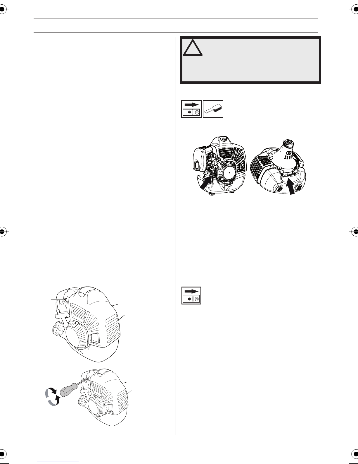
WARTUNG
Vergaser
Ihr Jonsered-Produkt wurde gemäß Spezifikationen
konstruiert und hergestellt, die die schädlichen Abgase
reduzieren. Wenn der Motor 8-10 Tankfüllungen Kraftstoff
verbraucht hat, ist er eingefahren. Um sicherzustellen,
dass der Motor optimal funktioniert und nach der
Einfahrzeit so wenig schädliche Abgase wie möglich
abgibt, lassen Sie Ihren Händler/Ihre Servicewerkstatt
(die einen Drehzahlmesser zur Verfügung hat) den
Vergaser einstellen.
Grundeinstellung
• Die Grundeinstellung des Vergasers wird beim
Probelauf im Werk vorgenommen. Die
Grundeinstellung ist fetter als die optimale Einstellung
und soll für die ersten Betriebsstunden des Geräts
beibehalten werden. Danach ist der Vergaser fein
einzustellen. Diese Feineinstellung ist von einem
Fachmann vorzunehmen.
ACHTUNG! Wenn die Schneidausrüstung sich im
Leerlauf dreht, ist die T-Schraube gegen den
Uhrzeigersinn zu drehen, bis die Schneidausrüstung
stehenbleibt.
Einstellung der Leerlaufdrehzahl
Vor den Einstellungen dafür sorgen, dass der Luftfilter
sauber und der Luftfilterdeckel angebracht ist.
Wenn eine Anpassung erforderlich wird, die
Leerlaufdrehzahl mit der Leerlaufschraube T einstellen.
Die Schraube T zunächst im Uhrzeigersinn drehen, bis
die Schneidausrüstung sich zu drehen beginnt. Danach
die T-Schraube gegen den Uhrzeigersinn drehen, bis die
Schneidausrüstung stehenbleibt. Eine korrekt
eingestellte Leerlaufdrehzahl ist dann erreicht, wenn der
Motor in jeder Situation gleichmäßig läuft. Es sollte
außerdem ein guter Abstand zu der Drehzahl bestehen,
bei der die Schneidausrüstung sich zu drehen beginnt.
WARNUNG! Kann die Leerlaufdrehzahl
!
nicht so eingestellt werden, dass die
Schneidausrüstung stehenbleibt, wenden
Sie sie an Ihren Händler/Ihre
Servicewerkstatt. Das Gerät erst wieder
verwenden, wenn es korrekt eingestellt
oder repariert ist.
Kühlsystem
Damit die Betriebstemperatur so niedrig wie möglich
bleibt, ist das Gerät mit einem Kühlsystem ausgestattet.
1
2
Das Kühlsystem besteht aus folgenden Komponenten:
1 Kühlluftöffnungen prüfen und reinigen.
2 Lufteinlass durch das Kurbelgehäuse (im Tank).
Das Kühlsystem einmal pro Woche mit einer Bürste
reinigen, bei schwierigen Verhältnissen öfter. Eine
Verschmutzung oder Verstopfung des Kühlsystems führt
zur Überhitzung des Gerätes, die Schäden an Zylinder
und Kolben zur Folge haben kann.
Zündkerze
T
Empf. Leerlaufdrehzahl: Siehe das Kapitel Technische
Daten.
72 – German
Der Zustand der Zündkerze wird durch folgende Faktoren
verschlechtert:
• Falsch eingestellter Vergaser.
• Falsche Ölmenge im Kraftstoff (zuviel Öl oder falsche
Ölsorte).
• Verschmutzter Luftfilter.
Diese Faktoren verursachen Beläge an den Elektroden
der Zündkerze und können somit zu Betriebsstörungen
und Startschwierigkeiten führen.
Bei schwacher Leistung, wenn das Gerät schwer zu
starten ist oder im Leerlauf ungleichmäßig läuft, immer
zuerst die Zündkerze prüfen, bevor andere Maßnahmen
eingeleitet werden. Ist die Zündkerze verschmutzt, so ist
sie zu reinigen; gleichzeitig ist zu prüfen, ob der
Elektrodenabstand 0,65 mm beträgt. Die Zündkerze ist
nach ungefähr einem Monat in Betrieb oder bei Bedarf
öfter auszuwechseln.
Page 73
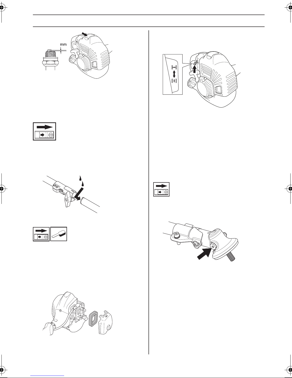
WARTUNG
0,65
ACHTUNG! Stets den vom Hersteller empfohlenen
Zündkerzentyp verwenden! Eine ungeeignete Zündkerze
kann Kolben und Zylinder zerstören. Dafür sorgen, dass
die Zündkerze eine sog. Funkentstörung hat.
Reinigung des Luftfilters
Schließen Sie die Drosselluftklappe, indem Sie den
Choke-Hebel nach oben bewegen.
Zerlegbares Führungsrohr
(GC2225C)
Das Ende der Antriebswelle im unteren Führungsrohr ist
alle 30 Betriebsstunden inwendig mit Fett zu schmieren.
Es besteht die Gefahr, dass sich die Enden der
Antriebswelle (Nutungsverband) bei den zerlegbaren
Modellen ineinander fressen, wenn sie nicht regelmäßig
geschmiert werden.
Luftfilter
Luftfilter regelmäßig von Staub und Schmutz reinigen, zur
Vermeidung von:
• Vergaserstörungen
• Startschwierigkeiten
• Leistungsminderung
• Unnötigem Verschleiß der Motorteile.
• Unnormal hohem Kraftstoffverbrauch.
Das Luftfiltergehäuse demontieren und den Filter
herausnehmen. Den Filter in warmer Seifenlauge
waschen. Mithilfe von Druckluft oder einer Bürste auch
das Innere des Filterdeckels reinigen. Dafür sorgen, dass
der Filter trocken ist, wenn er wieder montiert wird.
Ein Luftfilter, der längere Zeit verwendet wurde, wird nie
vollkommen sauber. Der Luftfilter ist daher in
regelmäßigen Abständen auszuwechseln. Beschädigte
Filter sind immer auszuwechseln. Beschädigte, stark
verschmutzte oder in Kraftstoff getränkte Filter sind
immer auszuwechseln.
Winkelgetriebe
Das Winkelgetriebe ist ab Werk mit der richtigen Menge
Fett gefüllt. Bevor das Gerät in Betrieb genommen wird,
sollte jedoch kontrolliert werden, ob das Getriebe zu 3/4
mit Fett gefüllt ist. JONSERED Spezialfett verwenden.
Das Schmiermittel im Getriebegehäuse braucht
normalerweise nur bei evtl. Reparaturen gewechselt zu
werden.
Den Filter jeweils nach 25 Betriebsstunden reinigen, bei
besonders staubigen Verhältnissen häufiger.
German – 73
Page 74

WARTUNG
Wartungsschema
Nachstehend sind die an der Maschine vorzunehmenden Wartungsmaßnahmen aufgelistet.Die meisten der Punkte
werden im Abschnitt ”Wartung” beschrieben. Der Bediener darf nur die Wartungs- und Servicearbeiten ausführen, die
in dieser Bedienungsanleitung beschrieben sind.Größere Eingriffe sind von einer autorisierten Servicewerkstatt
auszuführen.
Wartung
Das Gerät äußerlich reinigen. X
Kontrollieren, ob Gashebelsperre und Gashebel
ordnungsgemäß funktionieren.
Die Funktion des Stoppschalters kontrollieren. X
Kontrollieren, ob die Schneidausrüstung im Leerlauf rotiert. X
Luftfilter reinigen. Bei Bedarf austauschen. X
Den Schutz auf Schäden und Risse kontrollieren. Den Schutz
austauschen, wenn er Schlägen ausgesetzt war oder Risse
aufweist.
Den Trimmerkopf auf Schäden und Rissbildung kontrollieren. Bei
Bedarf den Trimmerkopf austauschen.
Schrauben und Muttern nachziehen. X
Sicherstellen, dass von Motor, Tank oder Kraftstoffleitungen kein
Kraftstoff ausläuft.
Das Kühlsystem des Geräts reinigen. X
Die Startvorrichtung und ihr Startseil kontrollieren. X
Die Vibrationsdämpfer auf Beschädigung überprüfen. X
Die Zündkerze äußerlich reinigen. Die Zündkerze demontieren
und den Elektrodenabstand prüfen. Den Abstand auf 0,65 mm
einstellen oder die Zündkerze austauschen. Dafür sorgen, dass
die Zündkerze eine sog. Funkentstörung hat.
Den Vergaser von außen und den Bereich um ihn herum
reinigen.
Kontrollieren, ob das Winkelgetriebe zu 3/4 mit Schmiermittel
gefüllt ist. Bei Bedarf Spezialfett nachfüllen.
Kraftstofffilter auf Verschmutzungen oder Kraftstoffschlauch auf
Risse oder andere Schäden untersuchen.Bei Bedarf
austauschen.
Alle Kabel und Anschlüsse kontrollieren. X
Kupplung, Kupplungsfedern und Kupplungstrommel auf
Verschleiß kontrollieren.Bei Bedarf von einer autorisierten
Servicewerkstatt austauschen lassen.
Zündkerze austauschen. Dafür sorgen, dass die Zündkerze eine
sog. Funkentstörung hat.
Tägliche
Wartung
X
X
X
X
Wöchentliche
Wartung
X
X
X
Monatliche
Wartung
X
X
X
74 – German
Page 75

TECHNISCHE DATEN
Technische Daten
GC2225 GC2225C
Motor
Hubraum, cm
Bohrung, mm 34,0 34,0
Hublänge, mm 28 28
Leerlaufdrehzahl, U/min 3000 3000
Empfohlene max. Drehzahl, unbelastet, U/min 9500±500 9500±500
Drehzahl der Abtriebswelle, U/min 6500 6500
Motorhöchstleistung gemäß ISO 8893, kW/ U/min 1,0/8500 1,0/8500
Katalysatorschalldämpfer Nein Nein
Drehzahlgeregeltes Zündsystem Ja Ja
Zündanlage
Hersteller/Typ des Zündsystems IKEDA/UK IKEDA/UK
Zündkerze NGK BPMR8Y NGK BPMR8Y
Elektrodenabstand, mm 0,65 0,65
Kraftstoff- und Schmiersystem
Hersteller/Vergasertyp Walbro WYA-218 Walbro WYA-218
Kraftstofftank, Volumen, Liter 0,65 0,65
Gewicht
Gewicht, ohne Kraftstoff, Schneidausrüstung und Schutz, kg 4,4 4,7
Geräuschemissionen
(siehe Anmerkung 1)
Gemessene Schallleistung dB(A) 109 109
Garantierte Schallleistung L
Schallpegel
(siehe Anmerkung 2)
Äquivalenter Schalldruckwert am Ohr des Anwenders,
gemessen gem. EN/ISO 11806 und ISO 7917, dB(A), min./max.:
Vibrationspegel
(siehe Anmerkung 3)
Äquivalente Vibrationspegel (a
gemäß EN ISO 11806 und ISO 22867, m/s
Ausgestattet mit Trimmerkopf (Original), links/rechts 4,4/2,5 4,3/2,6
3
dB(A) 111 111
WA
) an den Griffen, gemessen
hv,eq
2
25,4 25,4
101 101
Anmerkung 1: Umweltbelastende Geräuschemission gemessen als Schallleistung (LWA) gemäß EG-Richtlinie 2000/14/
EG. Der aufgezeichnete Lautstärkepegel für die Maschine wurde unter Verwendung der originalen Schneidausrüstung
mit dem höchsten Pegel gemessen. Die Differenz zwischen garantiertem und gemessenem Lautstärkepegel besteht
darin, dass bei der garantierten Lautstärke auch eine Streuung im Messergebnis und Variationen zwischen
verschiedenen Maschinen desselben Models gemäß der Richtlinie 2000/14/EG berücksichtigt werden.
Anmerkung 2: Berichten zufolge entspricht der Schalldruckpegel für diese Maschine normalerweise einer
Ausbreitungsklasse (standardmäßige Ausbreitung) von 1 dB (A).
Anmerkung 3: Berichten zufolge liegt der äquivalente Vibrationspegel normalerweise bei einer Ausbreitungsklasse
(Standardabweichung) von 1 m/s
2
.
German – 75
Page 76

TECHNISCHE DATEN
GC2225, GC2225C
Zugelassenes Zubehör Typ
Gewinde Klingenachse M10
Kunststoffmesser Polytrim 503 93 42-02
Grasklinge/Grasmesser
Trimmerkopf
GC 2225C
Zugelassenes Zubehör Teile-Nr. Verwenden mit
Kultivatoraufsatz mit Führungsrohr CA 150 537 42 54-02 GC 2225C
Heckenscherezusatz mit Führungsrohr HA 110 537 19 66-03 GC 2225C
Heckenscherezusatz mit Führungsrohr HA 850 537 19 66-04 GC 2225C
Kehrwalzezusatz mit Führungsrohr SR600 537 19 67-02 GC 2225C
Trimmerzusatz mit Führungsrohr TA 850 537 35 35-02 GC 2225C
Sägezusatz mit Führungsrohr PA 1100 537 18 33-24 GC 2225C
Blasgerätzusatz BAC 952 71 19-21 GC 2225C
Grass 255-4 1" (Ø 255, 4 Zähne) 503 93 42-02
Grass 255-8 (Ø 255 8-Zähne) 503 93 42-04
Fix 35 503 93 42-04
Tap-N-Go 25 (L) 503 93 42-02
Tap-N-Go 35 / Tap-N-Go 35 Spin 503 93 42-04
Stützkappe Fest
Schutz für die
Schneidausrüstung, Teile-Nr.
EG-Konformitätserklärung
(nur für Europa)
Die Husqvarna AB, SE-561 82 Huskvarna, Schweden, Tel. +46-36-146500, erklärt hiermit, dass die Rasentrimmer
Jonsered GC2225, GC2225C von den Seriennummern des Baujahrs 2013 an (die Jahreszahl wird im Klartext auf dem
Typenschild angegeben, mitsamt einer nachfolgenden Seriennummer) den Vorschriften der RICHTLINIE DES RATES
entsprechen:
- vom 17. Mai 2006 „Maschinen-Richtlinie” 2006/42/EG
- vom 15. Dezember 2004 ”über elektromagnetische Verträglichkeit” 2004/108/EWG.
- vom 8. Mai 2000 ”über umweltbelastende Geräuschemissionen von zur Verwendung im Freien vorgesehenen
Geräten und Maschinen” 2000/14/EG. Bewertung der Konformität wurde im Sinne von Anhang V durchgeführt.
Für Information betreffend die Geräuschemissionen, siehe das Kapitel Technische Daten.
Folgende harmonisierte Normen wurden angewendet: EN ISO 12100:2010, EN ISO 11806-1:2011, ISO 14982:2009,
CISPR 12:2009
SMP Svensk Maskinprovning AB, Box 7035, SE-750 07 Uppsala, Schweden, hat die freiwillige Typenprüfung für
Husqvarna AB durchgeführt. Die Prüfzertifikate haben die Nummern: SEC/13/2387 - GC 2225, GC 2225C
Huskvarna, den 21. Dezember 2013
Per Gustafsson, Entwicklungsleiter (Bevollmächtigter Vertreter für Husqvarna AB, verantwortlich für die technische
Dokumentation.)
76 – German
Page 77

SIMBOLOGIA
Simboli
AVVERTENZA! Gli sfrascatori, i
decespugliatori e i bordatori possono
essere pericolosi! L’uso negligente o
improprio può provocare lesioni gravi o
mortali all’utilizzatore o a terzi. È
estremamente importante leggere attentamente e
comprendere il contenuto del manuale dell’operatore.
Prima di usare la macchina,
leggere per intero le istruzioni per
l’uso e accertarsi di averne
compreso il contenuto.
Usare sempre:
• Casco di protezione laddove
sussiste il rischio di caduta di
oggetti
• Protezioni acustiche omologate
• Protezione per gli occhi omologata
Regime di fuga massimo
consigliato dell’albero sporgente,
10000
giri/min
Pericolo di proiezione di oggetti e
particelle.
Durante il lavoro l’utilizzatore della
macchina deve accertarsi che non ci
siano persone o animali in un raggio
15 m
50FT
15
m
5
0
FT
di 15 metri.
Le macchine dotate di lame da taglio
o sfalcio possono essere scagliate
violentemente a lato in caso di
contatto della lama con un oggetto
fisso. Questo fenomeno è
denominato contraccolpo della lama. La lama può
amputare un braccio o una gamba. Tenere sempre
persone e animali domestici ad almeno 15 metri dalla
macchina.
Le frecce indicano i limiti entro i quali
viene fissato l’attacco dell’impugnatura.
Utilizzare sempre guanti protettivi
omologati.
Usare stivali robusti e antisdrucciolo.
Pompa carburante
Emissioni di rumore nell’ambiente in
base alla direttiva della Comunità
Europea. L’emissione della macchina
è indicata al capitolo Dati tecnici e
sulla decalcomania.
I restanti simboli/decalcomanie riguardano
particolari requisiti necessari per ottenere la
certificazione in alcuni mercati.
Il motore si ferma portando il contatto
di arresto in posizione di arresto. N.B!
Il contatto di arresto torna
automaticamente in posizione di
avviamento. Prevenire l’avviamento
involontario staccando sempre il cappuccio dalla candela
prima di effettuare operazioni di montaggio, controllo e/o
manutenzione.
Utilizzare sempre guanti protettivi
omologati.
E’ necessario pulire con regolarità.
Controllo visivo.
Italian – 77
Page 78

INDICE
Indice Prima dell’avviamento osservare
SIMBOLOGIA
Simboli .................................................................. 77
INDICE
Indice .................................................................... 78
Prima dell’avviamento osservare quanto segue: .. 78
INTRODUZIONE
Alla gentile clientela .............................................. 79
CHE COSA C’È?
Che cosa c’è? ....................................................... 80
NORME GENERALI DI SICUREZZA
Importante ............................................................ 81
Abbigliamento protettivo ....................................... 81
Dispositivi di sicurezza della macchina ................. 82
Attrezzatura di taglio ............................................. 85
MONTAGGIO
Montaggio dell’impugnatura ad anello .................. 87
Montaggio dell’impugnatura a J ........................... 87
Montaggio del gancio di sospensione ................... 87
Montaggio del gruppo di taglio .............................. 87
Montaggio di protezione della testina e testina
portafilo ................................................................. 88
Montaggio e smontaggio di albero cavo
smontabile ............................................................ 88
Montaggio di paralama, lama tagliaerba e coltello
tagliaerba .............................................................. 89
OPERAZIONI CON IL CARBURANTE
Carburante ............................................................ 90
Carburante ............................................................ 90
Rifornimento ......................................................... 91
AVVIAMENTO E ARRESTO
Controlli prima dell’avviamento ............................. 92
Avviamento e arresto ............................................ 92
TECNICA DI LAVORO
Istruzioni generali di lavoro ................................... 94
MANUTENZIONE
Carburatore ........................................................... 97
Sistema di raffreddamento .................................... 97
Candela ................................................................ 97
Albero cavo smontabile ......................................... 98
Filtro dell’aria ........................................................ 98
Schema di manutenzione ..................................... 99
CARATTERISTICHE TECNICHE
Caratteristiche tecniche ........................................ 100
Dichiarazione di conformità CE ............................ 101
quanto segue:
Leggere accuratamente le istruzioni per l’uso.
AVVERTENZA! Una lunga esposizione al
!
!
!
rumore può comportare lesioni
permanenti all'udito. Usare quindi
sempre cuffie di protezione omologate.
AVVERTENZA! Evitare assolutamente di
modificare la versione originale della
macchina senza l’autorizzazione del
fabbricante. Usare sempre accessori
originali. Modifiche e/o accessori non
autorizzati possono causare lesioni gravi
o mortali all’operatore o a terzi.
AVVERTENZA! Usati in maniera
impropria o negligente lo sfrascatore, il
decespugliatore e il bordatore possono
essere attrezzi pericolosi, in grado di
provocare lesioni gravi o mortali
all’utilizzatore o a terzi. È
importantissimo leggere attentamente e
capire queste istruzioni per l’uso.
78 – Italian
Page 79

INTRODUZIONE
Alla gentile clientela
Congratulazioni per aver scelto di acquistare un prodotto Jonsered!
Siamo convinti che sarete pienamente soddisfatti della qualità e delle prestazioni del nostro prodotto per un lungo tempo
a venire. L'acquisto di uno dei nostri prodotti vi garantisce l'accesso alla competenza di personale qualificato per
l'assistenza e le riparazioni in caso di necessità. Se non avete acquistato la macchina presso uno dei nostri rivenditori
autorizzati, rivolgetevi alla più vicina officina di assistenza.
Ci auguriamo che rimarrete soddisfatti della vostra macchina e speriamo di potervi servire per molto tempo in futuro.
Non dimenticate che questo manuale delle istruzioni è un documento di valore. Seguendone il contenuto (uso,
assistenza, manutenzione ecc.) potrete aumentare notevolmente la durata della vostra macchina e anche il suo valore
di usato. Se vendete la macchina, ricordate di consegnare il manuale delle istruzioni al nuovo proprietario.
Buona fortuna nell’uso del vostro prodotto Jonsered!
La Jonsered procede costantemente allo sviluppo dei propri prodotti e si riserva quindi il diritto di apportare, senza alcun
preavviso, modifiche riguardanti fra l’altro la forma e l’aspetto esteriore.
Italian – 79
Page 80

CHE COSA C’È?
10
17
18
24
25
19
4
3
2
1
4
23
26
8
6
29
5
28
27
31
21
11
9
7
30
13
14
16
12
15
20
22
Che cosa c’è?
1 Testina portafilo
2 Rifornimento lubrificante, riduttore angolare
3 Riduttore angolare
4 Protezione del gruppo di taglio
5 Albero cavo
6 Impugnatura ad anello
7 Comando del gas
8 Interruttore di arresto
9 Fermo del gas
10 Cappuccio della candela e candela
11 Coperchio del cilindro
12 Maniglia di avviamento
13 Serbatoio carburante
14 Coperchio filtro aria
15 Pompa carburante
16 Comando valvola dell’aria
17 Dado di bloccaggio
18 Flangia di sostegno
19 Menabrida
20 Chiave combinata
21 Chiave Allen
22 Spina di bloccaggio
23 Istruzioni per l’uso
24 Coppetta di supporto
25 Lama
26 Raccordo dell’albero cavo (GC2225C)
27 Impugnatura a J
28 Regolazione impugnatura
29 Gancio di sospensione
30 Imbracatura
31 Protezione per trasporto
80 – Italian
Page 81

NORME GENERALI DI SICUREZZA
Importante Abbigliamento protettivo
IMPORTANTE!
Questa macchina è destinata esclusivamente all’uso per
la bordatura di manti erbosi.
La normativa nazionale o locale potrebbe regolarne
l’utilizzo. Assicurare la conformità alla normativa in
vigore.
I soli accessori per azionare i quali vi è permesso l’uso
del motore sono i gruppi di taglio da noi consigliati nel
capitolo Dati tecnici.
Non usare la macchina in condizioni di stanchezza o
sotto l’effetto si alcool o medicinali in grado di
compromettere il vostro stato psichico e il controllo dei
vostri atti.
Usare sempre abbigliamento protettivo. Vedi istruzioni
alla voce Abbigliamento protettivo.
Non usare mai una macchina che abbia subito modifiche
tali da non corrispondere più alle specifiche originali.
Non usare mai una macchina difettosa. Effettuare i
controlli di sicurezza e attenersi alle istruzioni di
manutenzione e riparazione riportate nel presente
manuale. Alcuni interventi devono essere eseguiti da
personale specializzato. Vedere le istruzioni alla sezione
Manutenzione.
Tutti i carter, le protezioni e le impugnature devono
essere montati prima di avviare la macchina. Accertarsi
che il cappuccio della candela e il cavo di accensione non
siano danneggiati per evitare il rischio di scossa elettrica.
L'operatore deve accertarsi che persone o animali non si
avvicinino entro un raggio di 15 metri durante il lavoro.
Nel caso in cui più utenti stiano lavorando nella stessa
zona, la distanza di sicurezza deve essere almeno 15
metri.
IMPORTANTE!
Usati in maniera impropria o negligente lo sfrascatore, il
decespugliatore e il bordatore possono essere attrezzi
pericolosi, in grado di provocare lesioni gravi o mortali
all’utilizzatore o a terzi. È importantissimo leggere
attentamente e capire queste istruzioni per l’uso.
Lavorando con la macchina usare sempre abbigliamento
protettivo omologato. L’uso di abbigliamento protettivo
non elimina i rischi di lesioni, ma riduce gli effetti del
danno in caso di incidente. Consigliatevi con il vostro
rivenditore di fiducia per la scelta dell’attrezzatura
adeguata.
AVVERTENZA! Far sempre attenzione a
!
CASCO
Casco di protezione laddove sussiste il rischio di caduta
di oggetti
CUFFIE PROTETTIVE
Usare cuffie protettive con effetto insonorizzante
adeguato.
segnali di allarme o chiamate quando
usate le cuffie protettive. Togliere sempre
le cuffie protettive immediatamente
all’arresto del motore.
AVVERTENZA! Questa macchina genera
!
!
!
un campo elettromagnetico durante il
funzionamento che in determinate
circostanze può interferire con impianti
medici attivi o passivi. Per ridurre il
rischio di gravi lesioni personali o mortali,
i portatori di tali impianti devono
consultare il proprio medico e il relativo
produttore prima di utilizzare la macchina.
AVVERTENZA! Un motore acceso in un
ambiente chiuso o mal ventilato può
essere causa di morte per soffocamento o
avvelenamento da monossido di carbonio.
AVVERTENZA! Non consentire mai a
bambini di utilizzare la macchina o
avvicinarsi a essa. Poiché la macchina è
dotata di contatto di arresto con ritorno a
molla e può avviarsi a bassa velocità con
una leggera trazione dell’impugnatura di
avviamento, in alcune condizioni la
macchina potrebbe essere avviata anche
da bambini piccoli. Sussiste il rischio di
gravi lesioni personali. Staccare quindi il
cappuccio dalla candela quando si lascia
la macchina incustodita.
PROTEZIONE PER GLI OCCHI
Usare sempre protezione per gli occhi omologata. Con
l’uso della visiera è necessario anche l’uso di occhiali
protettivi omologati. Con il termine occhiali protettivi
omologati si intendono occhiali che siano conformi alle
norme ANSI Z87.1 per gli USA o EN 166 per i paesi EU.
GUANTI
Usare i guanti quando è necessario, per es. durante il
montaggio del gruppo di taglio.
Italian – 81
Page 82
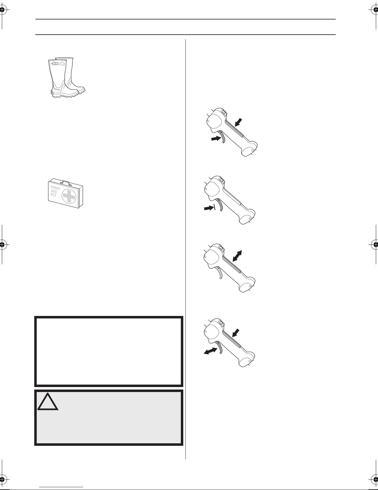
NORME GENERALI DI SICUREZZA
STIVALI
Utilizzare stivali con calotta di acciaio e suola antiscivolo.
ABBIGLIAMENTO
Usare abbigliamento in materiale robusto ed evitare
indumenti troppo ampi che si impigliano facilmente fra
rami e sterpi. Usare sempre pantaloni lunghi di tessuto
resistente. Non indossare gioielli, pantaloni corti o sandali
e non lavorare a piedi nudi. Accertarsi che i capelli non
scendano al di sotto delle spalle.
PRONTO SOCCORSO
Tenere sempre a portata di mano la cassetta di pronto
soccorso.
Dispositivi di sicurezza della
Fermo del gas
Il fermo del gas impedisce le accelerazioni involontarie.
Quando il fermo (A) viene premuto nell’impugnatura
(mentre si impugna la motosega), si libera il comando del
gas (B). Rilasciando l’impugnatura l’acceleratore e il
fermo si bloccano nella loro posizione di riposo. Questo
meccanismo è azionato da due molle di ritorno
indipendenti. In questa posizione il gas è bloccato
automaticamente sul minimo.
A
B
Controllare che l’acceleratore sia bloccato sul minimo
quando il fermo è in posizione di riposo.
macchina
In questo capitolo vengono presentati i dispositivi di
sicurezza della macchina, la loro funzione, il controllo e la
manutenzione necessari per assicurarne una funzione
ottimale. Vedi al capitolo Che cosa c’è?, per individuare la
posizione di questi componenti sulla macchina.
La durata della macchina può ridursi e il rischio di
incidenti aumentare se la manutenzione non viene
eseguita correttamente e se l'assistenza e/o le riparazioni
non vengono effettuate da personale qualificato. Per
ulteriori informazioni rivolgersi alla più vicina officina di
assistenza.
IMPORTANTE!
Tutte le riparazioni e l’assistenza della macchina vanno
eseguite da personale specializzato. Questo vale
soprattutto per i dispositivi di sicurezza. Se la macchina
non supera tutti i controlli sottoelencati, contattare
l’officina autorizzata. L’acquisto di uno dei nostri prodotti
garantisce l’assistenza di personale qualificato. Se non
avete acquistato la macchina presso un rivenditore con
centro di assistenza, informatevi sull’ubicazione della più
vicina officina autorizzata.
AVVERTENZA! Non usare mai una
!
macchina con dispositivi di sicurezza
guasti. Questi dispositivi vanno controllati
e sottoposti a manutenzione secondo
quanto descritto in questo capitolo. Se la
macchina non supera tutti i controlli,
contattare un’officina per le necessarie
riparazioni.
Premere sul fermo del gas e controllare che ritorni in
posizione di riposo non appena viene rilasciato.
Controllare che acceleratore e fermo del gas si muovano
liberamente e che le molle di richiamo funzionino a
dovere.
Vedi istruzioni alla voce Avviamento. Avviare il motore ed
accelerare a pieno gas. Lasciar andare l’acceleratore e
accertarsi che il gruppo di taglio di taglio si fermi e resti
fermo. Se il gruppo di taglio ruota mentre l’acceleratore è
al minimo è necessario controllare la registrazione del
82 – Italian
Page 83

NORME GENERALI DI SICUREZZA
minimo sul carburatore. Vedi istruzioni alla voce
Manutenzione.
Interruttore di arresto
L’interruttore di arresto serve a spegnere il motore.
Mettere in moto e controllare che il motore si spenga
portando l’interruttore in posizione di arresto.
Sistema di smorzamento delle vibrazioni
Il sistema di smorzamento delle vibrazioni adottato,
elimina la maggior parte delle vibrazioni che si sviluppano
durante l’uso della macchina.
L’uso di un filo avvolto nel modo errato e di un gruppo di
taglio inadeguato aumenta il livello di vibrazioni. Vedi
istruzioni alla voce Attrezzatura di taglio.
Il sistema di smorzamento delle vibrazioni della macchina
riduce il trasferimento delle vibrazioni fra gruppo motore e
l’unità albero della macchina.
Protezione del gruppo di taglio
Questa protezione mira ad impedire che vengano lanciati
oggetti dal gruppo di taglio contro l’utilizzatore. Inoltre la
protezione impedisce che l’utilizzatore venga a contatto
con il gruppo di taglio.
Controllare che la protezione sia integra e priva di
incrinature. Sostituire la protezione se è stata sottoposta
a urti o se è incrinata.
Usare sempre la protezione consigliata per ogni specifico
gruppo di taglio. Vedi capitolo Dati tecnici.
AVVERTENZA! Non usare mai in nessun
!
caso alcun gruppo di taglio senza che sia
stato montato un dispositivo di
protezione omologato. Vedi capitolo Dati
tecnici. Il montaggio di un dispositivo di
protezione inadeguato o difettoso può
provocare gravi lesioni alle persone.
Controllare con regolarità che gli smorzatori non siano
deformati o lesi. Controllare che gli elementi
ammortizzatori siano integri e ben fissati.
AVVERTENZA! L’esposizione eccessiva
!
alle vibrazioni può causare lesioni neurovascolari a chi soffre di disturbi
circolatori. In caso di sintomi riferibili ad
un’esposizione eccessiva alle vibrazioni,
contattare il medico. Tali sintomi
possono essere torpore, perdita della
sensibilità, punture, prurito, dolore,
riduzione o perdita della forza,
decolorazioni della pelle o modifiche
strutturali della sua superficie. tali
sintomi si riscontrano soprattutto nelle
mani, nei polsi e alle dita.
Italian – 83
Page 84

NORME GENERALI DI SICUREZZA
Marmitta
La marmitta è costruita in modo da assicurare il minimo
livello di rumorosità e da allotanare i gas di scarico del
motore dall’operatore.
È di estrema importanza seguire le istruzioni relative a
controllo, manutenzione e servizio della marmitta.
Non usare mai la macchina se la marmitta è in cattive
condizioni.
Controllare con regolarità che la marmitta sia ben fissa
nella macchina.
Dado di bloccaggio
Su alcuni tipi di gruppo di taglio si usa il dado di
bloccaggio per fissare l’utensile.
Durante il montaggio, avvitare il dado girando in senso
contrario a quello di rotazione del gruppo di taglio.
Durante lo smontaggio, svitare il dado nel senso di
rotazione del gruppo di taglio. (NOTA! La filettatura del
dado è sinistrorsa.)
Svitando e avvitando il dado della lama per sfrascatura
c’è pericolo di ferirsi con i denti della lama. Accertarsi
quindi che la mano sia riparata dal paralama durante
questa operazione. A questo proposito utilizzare sempre
una chiave a bussola dal manico sufficientemente lungo.
La freccia in figura mostra la zona di utilizzo della chiave
a bussola quando si avvita e si svita il dado.
AVVERTENZA! L’interno della marmitta
!
contiene sostanze chimiche che
potrebbero essere cancerogene. Evitare
il contatto con queste sostanze in caso
di marmitta danneggiata.
AVVERTENZA! Non dimenticate che:
!
I gas di scarico del motore sono molto
caldi e possono contenere scintille in
grado di provocare incendi. Non avviare
mai la macchina in ambienti chiusi o
vicino a materiale infiammabile!
84 – Italian
Il blocco di nylon del dado di bloccaggio non deve essere
talmente usurato da poter essere girato a mano. Il blocco
deve sopportare almeno 1,5 Nm. Quando è stato avvitato
circa 10 volte, il dado va sostituito.
Page 85
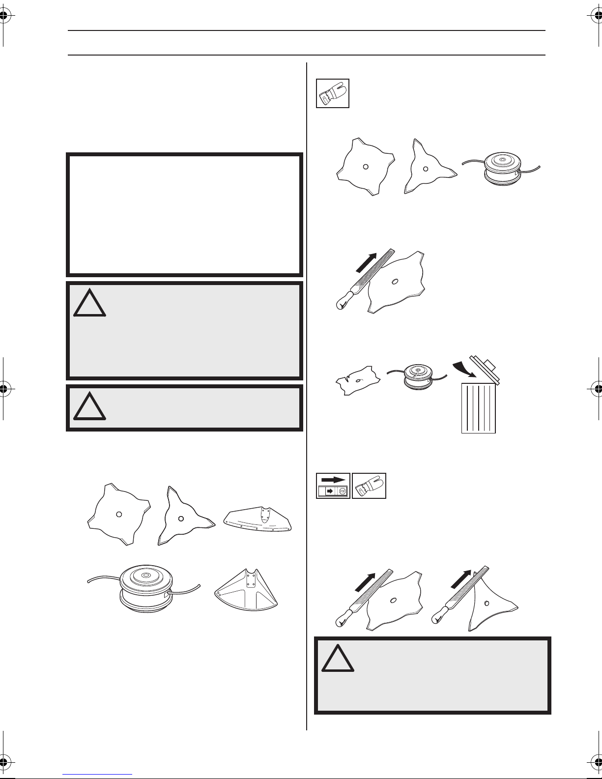
NORME GENERALI DI SICUREZZA
Attrezzatura di taglio
Questa parte vi indica, con la corretta manutenzione e
l’uso del tipo di attrezzatura di taglio, come:
• Ridurre la tendenza al contraccolpo della macchina.
• Ottenere sempre le migliori prestazioni di taglio.
• Aumentare la durata dell’attrezzatura di taglio.
IMPORTANTE!
Usare solo gruppi di taglio abbinati ai tipi di protezione
da noi raccomandati! Vedi capitolo Dati tecnici.
Per un corretto montaggio del filo e per la scelta di un
filo dal diametro adatto vedere le istruzioni per il gruppo
di taglio.
Mantenere i denti della lama affilati accuratamente e nel
modo giusto! Seguire le nostre indicazioni. Vedere
anche le istruzioni sulla confezione della lama.
AVVERTENZA! Spegnere sempre il
!
motore prima di eseguire qualsiasi
operazione sul gruppo di taglio. Questo
infatti continua a ruotare anche quando
l’acceleratore viene rilasciato. Accertarsi
che il gruppo di taglio sia completamente
fermo e staccare il cavo dalla candela
prima d’iniziare qualunque operazione.
Regole basilari
Usare solo gruppi di taglio abbinati ai tipi di protezione da
noi raccomandati! Vedi capitolo Dati tecnici.
Mantenere i denti della lama adeguatamente affilati!
Seguire le nostre istruzioni ed usare la sagoma di
affilatura consigliata. Una lama mal affilata o danneggiata
aumenta il rischio d’incidenti.
Controllare il gruppo di taglio per individuare danni o
incrinature. Un gruppo di taglio danneggiato dev’essere
sostituito.
AVVERTENZA! Un gruppo di taglio errato
!
o una lama affilata in modo sbagliato
aumentano il rischio di contraccolpi.
Attrezzatura di taglio
La lama tagliaerba e il coltello tagliaerba sono adatti allo
sfoltimento dell’erba più folta.
La testina portafilo è adatta per la bordatura dell’erba.
Affilatura del coltello tagliaerba e della
lama tagliaerba
• Per una corretta affilatura vedere la confezione del
gruppo di taglio. La lama e il coltello si affilano con una
lima piatta a taglio semplice.
• Per mantenere l’equilibratura, limare ugualmente tutti
i taglienti.
AVVERTENZA! Rottamare sempre la
!
lama che sia piegata, contorta, lesionata,
incrinata o danneggiata in altro modo.
Non provate mai a raddrizzare una lama
piegata per riutilizzarla. Usare solo lame
originali del tipo raccomandato.
Italian – 85
Page 86
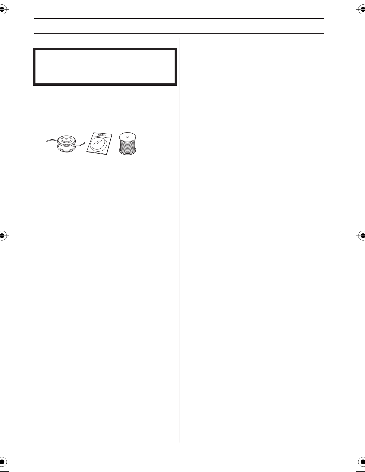
NORME GENERALI DI SICUREZZA
Testina portafilo
IMPORTANTE!
Controllare che il filo di taglio sia ben avvolto attorno al
rocchetto, onde evitare pericolose vibrazioni nella
macchina.
• Usare solo le testine portafilo ed i fili di taglio di tipo
consigliato. Essi sono stati collaudati dal fabbricante
ed adattati in base alla grandezza del motore. Ciò è
particolarmente importante se si usano testine
automatiche. Usare solamente i gruppi di taglio
consigliati. Vedi capitolo Dati tecnici.
• In genere una macchina piccola richiede una testina
portafilo piccola e viceversa. Questo dipende dal fatto
che il motore durante l’esercizio deve far ruotare il filo
allontanandolo in senso radiale dalla testina e
contemporaneamente superare la resistenza opposta
dall’erba.
• Anche la lunghezza del filo è importante. A parità di
diametro, un filo lungo richiede maggiore potenza
rispetto a uno corto.
• Assicurarsi che il coltellino situato sulla protezione
della testina sia intatto. Esso serve a tagliare il filo alla
giusta lunghezza.
• Per prolungare la vita del filo esso può essere
immerso in acqua per un paio di giorni. Il filo diventa
così più tenace e dura di più.
86 – Italian
Page 87
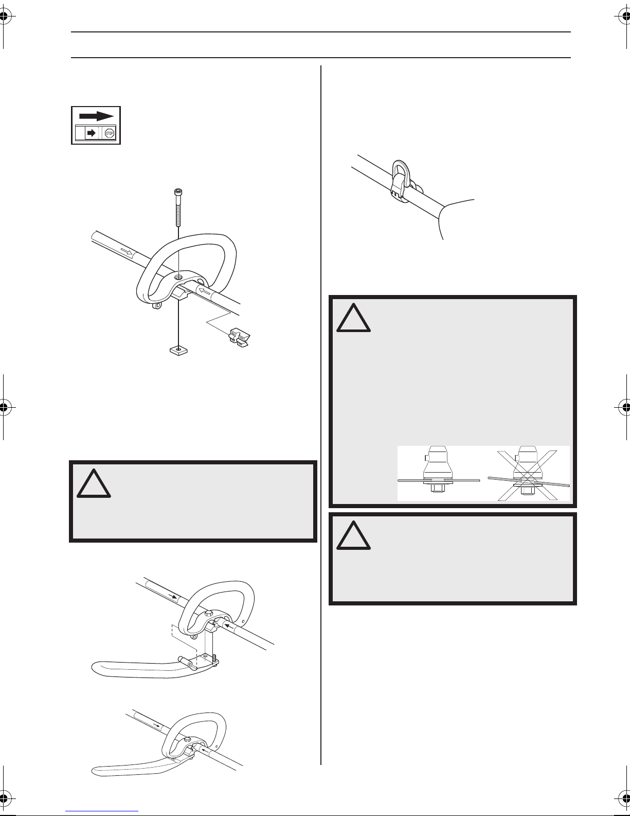
MONTAGGIO
Montaggio dell’impugnatura ad
anello
• Premere l’impugnatura ad anello sull’albero cavo.
Osservare che l’impugnatura ad anello dev’essere
montata fra le frecce segnate sull’albero cavo.
• Inserire il distanziale nella guida dell’impugnatura ad
anello. Montare il dado, la manopola e la vite. Non
serrare troppo.
• Eseguire ora la regolazione finale in modo da ottenere
una comoda posizione di lavoro con il bordatore.
Serrare la vite.
Montaggio del gancio di
sospensione
Il gancio di sospensione viene montato fra l’impugnatura
posteriore e l’impugnatura ad anello. Situare il gancio in
modo che la macchina sia ben bilanciata e risulti facile da
manovrare.
Afferrare il cinghiaggio e fissarlo al gancio di sospensione
in caso di utilizzo delle lame tagliaerba.
Montaggio del gruppo di taglio
AVVERTENZA!
!
Durante il montaggio del gruppo di taglio
è di estrema importanza fare in modo
che la guida del menabrida/flangia di
supporto sia situato nel modo corretto
nel foro centrale del gruppo di taglio. Un
gruppo di taglio montato in modo errato
può causare lesioni molto gravi e/o
perfino mortali.
Montaggio dell’impugnatura a J
AVVERTENZA! Con il montaggio
!
L’impugnatura a J viene montata nell’impugnatura ad
anello con tre viti come in figura.
Ora effettuare una regolazione precisa per ottenere una
posizione di lavoro comoda. Serrare le viti.
dell’impugnatura a J è possibile
utilizzare solo lama/coltello tagliaerba
oppure testina portafilo/coltelli in
plastica. Non usare mai una lama per
sfrascatura con l’impugnatura a J.
AVVERTENZA! Non usare mai in nessun
!
caso alcun gruppo di taglio senza che sia
stato montato un dispositivo di
protezione omologato. Vedi capitolo Dati
tecnici. Il montaggio di un dispositivo di
protezione inadeguato o difettoso può
provocare gravi lesioni alle persone.
Italian – 87
Page 88
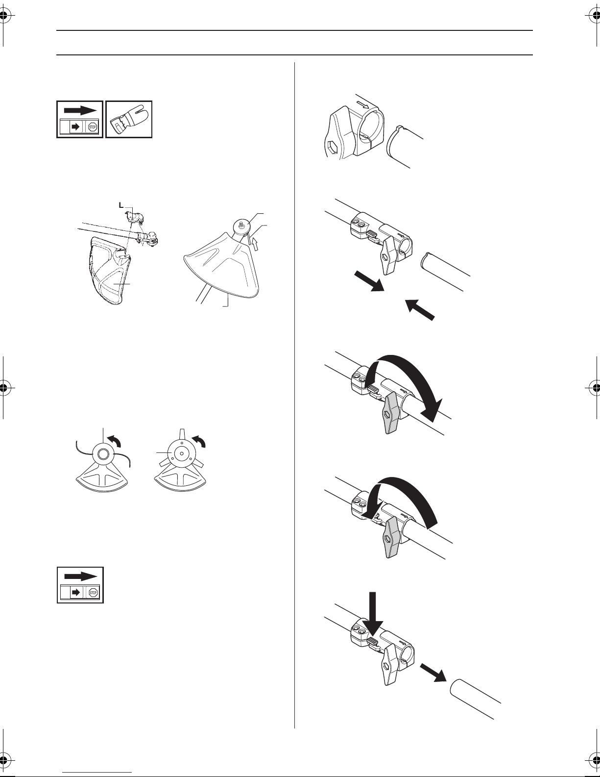
MONTAGGIO
Montaggio di protezione della
testina e testina portafilo
• Montare la protezione della testina (A) per le
operazioni con la testina portafilo. La protezione della
testina/protezione multipla viene agganciata al
supporto sull’albero cavo e fissata con 1 vite (L).
B
C
A
A
• Montare il menabrida (B) sull’alberino sporgente.
• Far ruotare l’alberino portalama fino a far coincidere
uno dei fori del menabrida con il foro corrispondente
nell’alloggiamento del riduttore.
• Introdurre nel foro la spina di bloccaggio (C) per
bloccare l’alberino.
• Avvitare la testina portafilo/coltelli in plastica (H) in
senso contrario al movimento di rotazione.
H
• Allineare la linguetta dell’accessorio (A) con la freccia
sull’attacco (B).
B
A
• Premere l’accessorio nell’attacco finché non scatta in
posizione.
• Prima di utilizzare l’unità, serrare saldamente il
pomello.
H
• Per smontare procedere in ordine inverso.
Montaggio e smontaggio di albero
cavo smontabile
(GC2225C)
Montaggio
• Allentare l’attacco girando il pomello.
Smontaggio
• Allentare l’attacco girando il pomello (di almeno 3 giri).
Tenere premuto il pulsante (C). Tenendo ferma l’estremità
del motore, sfilare l’accessorio in linea retta dall’attacco.
C
88 – Italian
Page 89

MONTAGGIO
Montaggio di paralama, lama
tagliaerba e coltello tagliaerba
G
F
E
D
A
B
C
il dado girare la chiave in senso contrario a quello di
rotazione (NOTA! filettatura sinistrorsa).
• Il paralama/protezione multipla (A) viene agganciato
al supporto sull’albero cavo e fissato con una vite.
N.B! Usare il paralama di tipo consigliato. Vedi istruzioni
alla voce Caratteristiche tecniche.
• Montare il menabrida (B) sull’alberino sporgente.
• Far ruotare l’alberino portalama fino a far coincidere
uno dei fori del menabrida con il foro corrispondente
nell’alloggiamento del riduttore.
• Introdurre nel foro la spina di bloccaggio (C) per
bloccare l’alberino.
• Collocare la lama (D), la coppetta di sostegno (E) e la
flangia di sostegno (F) sull’alberino sporgente.
• Montare il dado (G). Esso va serrato con una coppia
di 35-50 Nm (3,5-5 kpm). Usare la chiave a bussola
inclusa nel kit attrezzi. Mantenere il manico della
chiave il più possibile vicino al paralama. Per serrare
Italian – 89
Page 90

OPERAZIONI CON IL CARBURANTE
Carburante
Non accendere mai la macchina:
1 Se è stato versato del carburante sulla macchina.
Eliminare ogni traccia di sporco e lasciare evaporare i
resti di benzina.
2 Se avete versato del carburante su voi stessi o sui
vostri abiti, cambiare abiti. Lavare le parti del corpo
che sono venute a contatto con il carburante. Usare
acqua e sapone.
3 Se vi sono perdite di carburante nella macchina.
Controllare con regolarità la presenza di eventuali
perdite dal tappo del serbatoio o dai tubi di
alimentazione.
Trasporto e rimessaggio
• Il rimessaggio e il trasporto della macchina e del
carburante devono essere eseguiti in modo che
eventuali perdite o vapori non rischino di venire a
contatto con scintille o fiamme aperte, generate ad
esempio da macchine elettriche, motori elettrici,
contatti/interruttori o caldaie.
• Per il rimessaggio e il trasporto del carburante usare
recipienti adeguati ed omologati per tale scopo.
• In caso di rimessaggio della macchina per un periodo
prolungato il serbatoio del carburante va svuotato. Per
l’eliminazione dei resti inutilizzati di carburante
rivolgersi al più vicino distributore di benzina.
• Accertarsi che la macchina sia ben pulita e che sia
stata sottoposta a tutte le operazioni di assistenza
prima di ogni rimessaggio a lungo termine.
• Durante il trasporto e il rimessaggio della macchina la
protezione per il trasporto deve essere sempre
montata sul gruppo di taglio.
• Mettere in sicurezza la macchina durante il trasporto.
• Prevenire l’avviamento involontario staccando
sempre il cappuccio dalla candela in occasione di
lunghi periodi di rimessaggio, se la macchina resta
incustodita e prima di effettuare qualsiasi intervento di
assistenza.
AVVERTENZA! Il carburante va
!
maneggiato con cautela. Tenere presenti
i rischi d’incendio, esplosione e
intossicazione in caso di aspirazione.
Carburante
N.B! La macchina è dotata di motore a due tempi che
deve sempre funzionare con una miscela di benzina e olio
per motori a due tempi. Per assicurare una corretta
miscelazione, misurare con cura la quantità d’olio da
mescolare alla benzina. Se la quantità di carburante è
limitata, anche un piccolo errore nella quantità d’olio
influisce notevolmente sulla miscela.
AVVERTENZA! Il carburante e i vapori
!
90 – Italian
tossici sono altamente infiammabili e la
loro inalazione o il contatto cutaneo
possono provocare gravi lesioni. Agire
dunque con cautela maneggiando il
carburante e assicurare una buona
ventilazione dell'ambiente durante
l'operazione.
Benzina
N.B! Utilizzare sempre benzina di alta qualità, minimo 90
ottani (RON), miscelata a olio. Se la macchina è dotata di
marmitta catalitica (vedere il capitolo Dati tecnici),
utilizzare sempre benzina senza piombo di alta qualità
miscelata a olio. La benzina contenente piombo
danneggia la marmitta catalitica.
Usare nei casi in cui sia possibile una benzina ecologica,
la cosiddetta benzina alchilata.
È possibile utilizzare una miscela di carburante a base di
etanolo E10 (contenente fino al 10% di etanolo).
Utilizzando miscele di carburante contenenti oltre il 10%
di etanolo, il motore funzionerà in condizioni di
combustione povera, il che può essere causa di danni al
motore.
• Il numero minimo di ottani raccomandato è 90 (RON).
Se si utilizza una benzina con un numero di ottani
inferiore a 90, il motore può strappare. In tal caso la
temperatura del motore aumenta e possono
verificarsi gravi avarie.
• In caso di uso continuo ad alto regime si raccomanda
una benzina ad alto numero di ottani.
Olio per motori a due tempi
• Per un risultato ottimale, utilizzare l’olio per motori a
due tempi JONSERED, studiato appositamente per i
nostri motori a due tempi con raffreddamento ad aria.
• Non utilizzare mai olio per motori a due tempi
formulato per motori fuoribordo con raffreddamento
ad acqua (outboardoil - TCW).
• Non usare mai olio per motori a quattro tempi.
• Un olio di qualità scadente o una miscela carburante/
olio troppo ricca può pregiudicare il corretto
funzionamento della marmitta e ridurne la vita utile.
• Miscela
1:50 (2%) con olio per motori a due tempi
JONSERED.
1:33 (3%) con altri oli per motori a due tempi con
raffreddamento ad aria classificati a norma JASO FB/
ISO EGB.
Olio per motori a due tempi,
Benzina, litri
5 0,10 0,15
10 0,20 0,30
15 0,30 0,45
20 0,40 0,60
litri
2% (1:50) 3% (1:33)
Page 91

OPERAZIONI CON IL CARBURANTE
Preparazione della miscela
• Preparare la miscela in recipiente pulito e a parte,
omologato per la benzina.
• Iniziare con il versare metà della benzina da usare.
Aggiungere tutto l’olio. Mescolare agitando. Versare la
benzina rimanente.
• Mescolare (agitare) accuratamente prima di
procedere al rifornimento.
• Preparare una quantità di miscela necessaria al
massimo per un mese.
• In caso di rimessaggio prolungato, vuotare e pulire il
serbatoio del carburante.
Rifornimento
• Se è stato versato del carburante sulla macchina.
Eliminare ogni traccia di sporco e lasciare evaporare i
resti di benzina.
• Utilizzare una tanica carburante con protezione antitraboccamento.
• Pulire tutt’intorno al tappo del serbatoio. La presenza
d’impurità nel serbatoio può causare guasti.
• Agitare il contenitore della miscela prima di versarla
nel serbatoio per assicurarsi che essa sia ben
mescolata.
AVVERTENZA! I seguenti accorgimenti
!
diminuiscono il pericolo di incendio:
Miscelare e versare il carburante
all'esterno dove non sono presenti
fiamme libere o scintille.
Non fumare o portare sorgenti di calore
vicino al carburante.
Effettuare sempreil rifornimento a
motore spento.
Spegnere il motore e lasciarlo
raffreddare alcuni minuti prima del
rifornimento.
Aprire il tappo del serbatoio con cautela,
per eliminare eventuali sovrappressioni.
Dopo il rifornimento chiudere bene il
tappo.
Allontanare sempre la macchina dal
luogo e dalla fonte di rifornimento prima
della messa in moto.
Italian – 91
Page 92

AVVIAMENTO E ARRESTO
Controlli prima dell’avviamento
Controllare la lama per accertarsi che non vi siano
incrinature sul fondo dei denti o presso il foro centrale. Le
cause più frequenti delle incrinature sono il formarsi di
angoli acuti sui fondi dei denti durante l’affilatura e l’uso
della lama con i denti non affilati. In caso di incrinature
gettare via la lama.
• Non usare mai la macchina senza protezione o con
una protezione difettosa.
• Tutti i coperchi devono essere correttamente montati
e integri prima dell’avviamento della macchina.
Avviamento e arresto
• Controllare la flangia di sostegno assicurandosi che
non si siano formate incrinature dovute ad
affaticamento o ad un serraggio eccessivo. In caso di
incrinature, gettare via la flangia.
Controllare che il dado non abbia perso la sua capacità di
bloccaggio. Il blocco del dado deve sopportare una
coppia di almeno 1,5 Nm. La coppia di serraggio del dado
deve corrispondere a 35-50 Nm.
Controllare il paralama e verificare che non abbia subito
lesioni o incrinature. Sostituire il paralama nel caso in cui
abbia subito degli urti o presenti delle incrinature.
AVVERTENZA! Prima di avviare la
!
macchina il coperchio della frizione
completo e l’albero cavo devono essere
montati, altrimenti la frizione potrebbe
staccarsi e causare danni alle persone.
Allontanare sempre la macchina dal
luogo e dalla fonte di rifornimento prima
della messa in moto. Collocare la
macchina su una solida base
d’appoggio. Controllare che il gruppo di
taglio non possa venire a contatto con
corpi solidi.
Verificare che nella zona operativa non
siano presenti persone non addette ai
lavori, che sarebbero esposte al rischio
di gravi lesioni. La distanza di sicurezza
corrisponde a 15 metri.
Avviamento
Pompa carburante: Premere più volte il primer fino a
quando la sacca comincia a riempirsi di carburante. Non
è necessario che la sacca sia completamente piena.
• Controllare la testina portafilo e la protezione della
testina e verificare che siano intatte e non presentino
incrinature. Sostituire la testina portafilo o la
protezione della testina nel caso in cui abbiano subito
degli urti o presentino incrinature.
92 – Italian
Page 93

AVVIAMENTO E ARRESTO
Aria: Portare il comando della valvola dell’aria sulla
posizione di starter, spostandolo verso l’alto.
AVVERTENZA! Accendendo il motore
!
Premere il corpo della macchina contro il terreno con la
mano sinistra (NOTA! Non con il piede!).
Afferrare saldamente il fermo dell’acceleratore (A) e il
comando dell’acceleratore (B) con la sinistra, tirare la
manopola del motorino rapidamente fino a che il motore
non tenta l’avviamento o, al massimo, 5 volte.
con il comando della valvola dell’aria in
posizione di arricchimento o di
avviamento il gruppo di taglio inizia
immediatamente a ruotare.
N.B! Evitare di toccare la superficie contrassegnata con
qualunque parte del corpo. Il contatto può provocare
ustioni o scossa elettrica se il cappuccio della candela è
difettoso. Usare sempre i guanti. Non usare mai la
macchina se il cappuccio della candela è difettoso.
Arresto
Il motore si arresta immediatamente agendo
sull’interruttore.
A
B
Non avvolgere mai la cordicella di avviamento
intorno alla mano.
Dopo che il motore tenta l’avvio, o al massimo dopo 5
tentativi, portare la leva di comando dell’aria in posizione
RUN.
Afferrare il fermo dell’acceleratore (A) e il grilletto
dell’acceleratore (B) e continuare a tirare il filo finché il
motore non si avvia. Premere al massimo l’acceleratore
della macchina, quindi rilasciare il grilletto
dell’acceleratore. Una volta avviato, far riscaldare il
motore per almeno 30 secondi prima di andare a pieno
acceleratore.
N.B! Non estrarre completamente la cordicella e non
lasciare la maniglia di avviamento con la cordicella
estratta. Questo potrebbe danneggiare la macchina.
N.B! Il contatto di arresto torna automaticamente in
posizione di avviamento. Prevenire l’avviamento
involontario staccando sempre il cappuccio dalla candela
prima di effettuare operazioni di montaggio, controllo e/o
manutenzione.
Italian – 93
Page 94

TECNICA DI LAVORO
Istruzioni generali di lavoro
IMPORTANTE!
Questo capitolo comprende le regole fondamentali di
sicurezza per il lavoro con decespugliatore e bordatore.
Trovandosi in una situazione di insicurezza riguardo
all’uso della macchina rivolgersi ad un esperto.
Contattare il proprio rivenditore o l’officina di servizio.
Evitare qualsiasi lavoro per il quale non ci si sente
sufficientemente qualificati.
Prima dell’uso dovete comprendere la differenza fra
sfoltimento forestale, sfoltimento dell’erba e bordatura
dell’erba.
Dischi di taglio e coltelli tagliaerba possono essere
utilizzati esclusivamente con l’impugnatura a J, mentre i
dischi di taglio per motoseghe non devono mai essere
utilizzati con l’impugnatura a J. Afferrare il cinghiaggio e
fissarlo al gancio di sospensione in caso di utilizzo delle
lame tagliaerba.
Norme basilari di sicurezza
1 Osservare l’ambiente circostante:
• Per escludere la presenza di persone, animali o altro
che possa interferire sul vostro controllo della
macchina.
• Per impedire che persone, animali o altro possano
rischiare di entrare a contatto con il gruppo di taglio o
che oggetti possano essere scagliati in aria dal
gruppo di taglio.
• N.B! Non usare mai la macchina se non siete certi di
poter chiedere aiuto in caso d’infortunio.
2 Controllare l’area di lavoro. Asportare eventuali corpi
estranei quali pietre, frammenti di vetro, chiodi, fili di
ferro, corde ecc. che potrebbero essere scagliati
oppure penetrare nel gruppo di taglio.
3 Evitare di lavorare in condizioni di tempo sfavorevoli.
Ad esempio nebbia, pioggia intensa, vento forte ecc.
Il lavorare con tempo cattivo è spesso stancante e
comporta situazioni di rischio, come ad esempio il
terreno scivoloso, cambio di direzione di caduta
dell’albero ecc.
4 Accertarsi di poter camminare e lavorare in posizione
sicura. In caso di spostamenti, controllare che non vi
siano ostacoli (ceppi, radici, rami, fossati ecc.) Fare
particolare attenzione lavorando su terreni in
pendenza.
94 – Italian
5 Mantenere una posizione ben salda ed equilibrata.
6 Mantenere sempre una presa sicura della macchina
con entrambe le mani. Tenere la macchina sul lato
destro del corpo.
7 Tenere il gruppo di taglio al di sotto della vita.
8 Gli spostamenti vanno sempre eseguiti a motore
spento. In caso di spostamenti su distanze più lunghe
o di trasporti usare la protezione di trasporto.
9 Non poggiare mai la macchina a motore acceso se
non la si può tenere bene d’occhio.
AVVERTENZA! Non cercare mai di
!
rimuovere il materiale tagliato con il
motore in moto o il gruppo di taglio in
rotazione. Esiste il rischio di ferirsi
gravemente e ciò vale sia per l'operatore
che per eventuali terzi.
Arrestare il motore e il gruppo di taglio
prima di rimuovere il materiale avvolto
intorno all'albero della lama; in caso
contrario esiste il rischio di ferirsi
gravemente. Durante e/o alcuni attimi
dopo l’uso è possibile che il riduttore
angolare sia caldo. Il contatto può
implicare il rischio di ustioni.
AVVERTENZA! Rischio di oggetti volanti.
!
Usare sempre una protezione per gli
occhi omologata. Evitate di lavorare
inclinati verso la protezione del gruppo
di taglio. Esiste il rischio di venir colpiti
agli occhi da sassi o altri corpi estranei il
che potrebbe causare cecità o altre gravi
lesioni.
Mantenere sempre distanti i non addetti
ai lavori. Bambini, animali, assistenti e
anche eventuali spettatori devono
sempre essere tenuti ad una distanza di
sicurezza di 15 metri. Arrestare
immediatamente la macchina nel caso
qualcuno si avvicini. Non girarsi mai con
la macchina in azione senza prima aver
controllato che non ci sia nessuno alle
vostre spalle entro la zona di sicurezza.
Page 95

TECNICA DI LAVORO
Tecnica fondamentale di lavoro
Dopo ciascuna fase di lavoro decelerare il motore fino al
regime minimo. Un esercizio prolungato a pieno regime
senza carico può causare gravi danni al motore.
AVVERTENZA! A volte rami o erba
!
!
possono incastrarsi tra la protezione e il
gruppo di taglio. Spegnere sempre il
motore prima della pulizia.
AVVERTENZA! Le macchine dotate di
lame da taglio o sfalcio possono essere
scagliate violentemente a lato in caso di
contatto della lama con un oggetto fisso.
Questo fenomeno è denominato
contraccolpo della lama. Il contraccolpo
della lama può essere sufficientemente
violento per scagliare la macchina e/o
l’operatore in qualsiasi direzione ed
eventualmente provocare la perdita di
controllo della macchina. Il contraccolpo
della lama si può verificare senza alcun
segno di stallo o funzionamento
irregolare della macchina. Il
contraccolpo della lama si può verificare
più facilmente nei punti in cui è difficile
vedere il materiale tagliato.
Evitare di segare con il settore di lama
che è compreso tra le posizioni ore 12 e
ore 3. Per la velocità di rotazione della
lama vi è rischio di contraccolpi, se
questa parte della lama viene avvicinata
a tronchi di grosso spessore.
• Inclinando leggermente la lama verso sinistra durante
lo sfoltimento, l’erba forma un’andana che ne facilita la
raccolta col rastrello.
• Cercare di lavorare con movimenti ritmici. Assumere
una posizione stabile con i piedi divaricati. Dopo il
movimento di ritorno avanzare e riassumere una
posizione stabile.
• Fare in modo che la coppetta di sostegno si appoggi
leggermente al terreno. La coppetta di sostegno serve
a proteggere la lama dal contatto con il terreno.
• Per evitare che il tagliato si aggrovigli intorno alla lama
è bene seguire le seguenti indicazioni:
1Lavorare sempre a pieno gas.
2Evitare il materiale appena tagliato nel movimento di
ritorno.
• Arrestare il motore, sganciare l’imbracatura ed
appoggiare a terra la macchina prima di raccogliere il
materiale tagliato.
Bordatura dell’erba con testina portafilo
Bordatura
• Mantenere la testina portafilo a poca distanza dal
terreno ed angolarla. E’ l’estremità del filo che esegue
il taglio. Lasciare che il filo funzioni al proprio ritmo.
Non premere mai il filo contro il materiale da tagliare.
Sfoltimento dell’erba con lama tagliaerba
• Le lame tagliaerba e i coltelli tagliaerba non possono
essere usati per i tronchi legnosi.
• Per tutti i tipi di erba alta o robusta si usa la lama
tagliaerba.
• L’erba viene falciata con movimenti oscillanti
lateralmente, in cui il movimento da destra a sinistra
costituisce il momento di falciatura mentre il
movimento da sinistra a destra è il movimento di
ritorno. Lavorare col lato sinistro della lama
(prendendo ad esempio l’orologio, la posizione
sarebbe fra le 8 e le 12).
• Il filo elimina facilmente l’erba e le erbacce vicino a
muri, recinti, alberi ed aiuole, ma può anche
danneggiare la corteccia di alberi e cespugli oppure i
paletti dei recinti.
• Per ridurre i danni alle piante accorciare il filo fino a
10-12 cm e ridurre il regime del motore.
Estirpazione di erbacce
• La tecnica di estirpazione rimuove tutta la
vegetazione indesiderata. Tenere la testina portafilo
appena al di sopra del terreno ed inclinarla. Lasciare
che l’estremità del filo colpisca il terreno attorno ad
alberi, pilastri, statue o simili. NOTA! Questo metodo
comporta una maggiore usura del filo.
• Se si lavora contro pietre, mattoni, cemento, recinzioni
metalliche ecc. il filo si consuma più rapidamente che
non a contatto con alberi o steccati in legno.
• Durante la bordatura e l’estirpazione di erbacce
mantenere il regime al di sotto del massimo (80%),
per far sì che il filo duri di più e la testina portafilo si
usuri di meno.
Italian – 95
Page 96
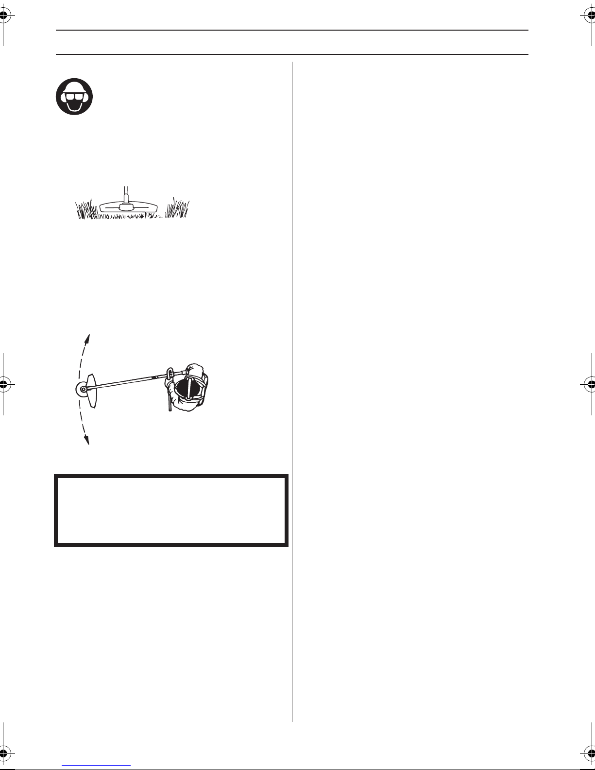
TECNICA DI LAVORO
Rasatura
• Il bordatore è ideale per tagliare l’erba in punti che un
normale rasaerba difficilmente può raggiungere.
Durante il taglio mantenere il filo parallelo al terreno.
Evitare di premere la testina portafilo contro il terreno
perché in questo modo si rischia di rovinare il manto
erboso e di danneggiare l’utensile.
• Durante le normali operazioni di taglio evitare che la
testina portafilo sia a contatto prolungato col terreno.
Un contatto costante potrebbe danneggiare o usurare
la testina.
Spazzare
• Lo spostamento d’aria causato dal filo rotante può
essere utilizzato per spazzare in modo facile e veloce.
Mantenere il filo parallelo e al di sopra delle superfici
da spazzare e muovere l’utensile avanti e indietro.
• Per rasare o spazzare procedere a pieno gas per
ottenere un buon risultato.
IMPORTANTE!
Per evitare perdite di equilibrio e vibrazioni sul
manubrio, la copertura della testina portafilo deve
essere pulita a ogni utilizzo del filo. Inoltre, controllare
se anche l’altra parte della testina deve essere pulita.
96 – Italian
Page 97
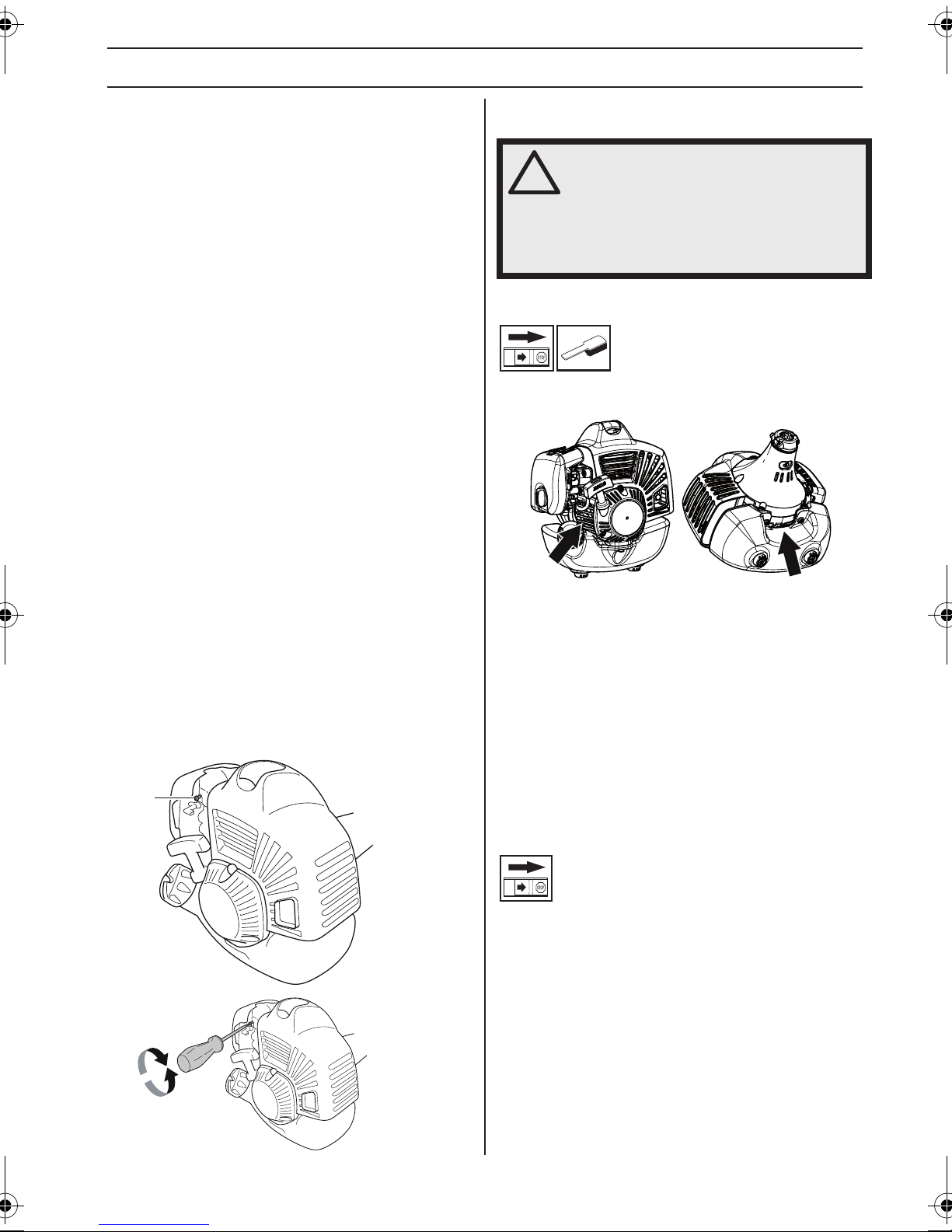
MANUTENZIONE
Carburatore
Il vostro prodotto Jonsered è stato fabbricato e prodotto in
base a norme che permettono di ridurre le emissioni di
scarico dannose. Dopo aver consumato 8-10 serbatoi di
carburante il motore ha passato il rodaggio. Per verificare
che il motore funzioni in modo ottimale con un minimo
livello di emissioni di scarico dopo il periodo di rodaggio,
rivolgetevi al vostro rivenditore/servizio di assistenza (che
ha accesso ad un contagiri) per registrare il carburatore.
Messa a punto iniziale
• Il carburatore è messo a punto al collaudo in fabbrica.
La messa a punto iniziale ha una miscela più ricca di
quella ottimale e dev’essere mantenuta durante le
prime ore di esercizio della macchina. In seguito il
carburatore dovrà essere sottoposto alla messa a
punto finale. La messa a punto finale sarà eseguita da
persona competente ed esperta.
N.B! Se il gruppo di taglio ruota con il motore al minimo
sarà necessario regolare la vite T in senso antiorario fino
all’arresto del gruppo di taglio.
Regolazione del regime minimo
Prima di effettuare ogni regolazione, verificate che il filtro
dell’aria sia pulito e che il coperchio del filtro dell’aria sia
al posto giusto.
Regolate il regime di giri al minimo servendovi della vite
del minimo T, nel caso sia necessaria una nuova messa a
punto. Girate prima la vite del minimo T in senso orario
fino a quando il gruppo di taglio comincia a ruotare. Girate
poi la vite in senso antiorario fino a quando il gruppo di
taglio si arresta. Il regime al minimo è regolato
correttamente quando il motore funziona uniformemente
in ogni posizione. Dovrebbe inoltre esserci un buon
margine fino al regime in cui il gruppo di taglio comincia a
ruotare.
T
Regime consigliato con motore al minimo: Vedi
istruzioni alla voce Caratteristiche tecniche.
AVVERTENZA! Se non è possibile
!
regolare il regime del minimo affinché il
gruppo di taglio si fermi, contattate il
rivenditore/servizio di assistenza. Evitate
di utilizzare la macchina prima che
questa sia stata correttamente regolata o
riparata.
Sistema di raffreddamento
La macchina è dotata di sistema di raffreddamento per
mantenere al minimo la temperatura di esercizio.
1
2
Il sistema è costituito da:
1 Controllare e pulire le aperture per l'aria di
raffreddamento.
2 Presa d' aria attraverso il carter motore (all'interno del
serbatoio).
Pulire il sistema di raffreddamento con una spazzola una
volta la settimana, più spesso se necessario. Se il
sistema di raffreddamento è sporco o ostruito provoca il
surriscaldamento della macchina, con conseguenti danni
a cilindro e pistone.
Candela
Lo stato della candela dipende da:
• Carburatore non tarato.
• Miscela carburante/olio non corretta (quantità
eccessiva di olio oppure olio non idoneo).
• Filtro dell’aria ostruito .
Questi fattori causano depositi sull’elettrodo della
candela, e conseguenti disturbi di funzionamento e di
messa in moto.
Se la macchina ha potenza insoddisfacente, difficoltà di
messa in moto o il minimo irregolare, controllare
innanzitutto la candela. Se questa è incrostata, pulirla e
controllare la distanza tra gli elettrodi, che deve essere
Italian – 97
Page 98

MANUTENZIONE
0,65 mm. La candela andrebbe cambiata di regola dopo
circa un mese di esercizio o prima se necessario.
0,65
N.B! Usare candele originali o di tipo raccomandato!
Altre candele possono danneggiare cilindro e pistone.
Controllare che la candela sia munita di dispositivo di
soppressione interferenze radio.
Albero cavo smontabile
(GC2225C)
L’estremità dell’albero di trasmissione nella sezione
inferiore dell’albero cavo dev’essere ingrassata
internamente ogni 30 ore di esercizio. Esiste il rischio che
le estremità dell’albero di trasmissione (innesti) sui
modelli smontabili grippino se non vengono ingrassate
regolarmente.
Pulizia del filtro dell’aria
Chiudere la valvola dell’aria spostando il comando della
valvola dell’aria verso l’alto.
Smontare il coperchio del filtro dell’aria ed estrarre il filtro.
Lavarlo in acqua saponata calda. Pulire anche l'interno
del coperchio del filtro con aria o con una spazzola. Prima
di rimontare il filtro accertarsi che sia ben asciutto.
Il filtro non ritorna mai completamente pulito. Pertanto va
sostituito periodicamente con uno nuovo. Un filtro
danneggiato va sostituito immediatamente. I filtri
dell'aria danneggiati, molto sporchi o imbevuti di
carburante devono essere sempre sostituiti
immediatamente.
Riduttore angolare
Filtro dell’aria
Pulire regolarmente il filtro dell’aria per evitare :
• Disturbi di carburazione
• Problemi di messa in moto
• Riduzione della potenza sviluppata
• Inutile usura dei componenti del motore
• Consumi più elevati.
Il riduttore angolare è stato riempito in fabbrica con la
giusta quantità di grasso. Prima dell’uso della macchina si
consiglia comunque di controllare che il riduttore sia
pieno di grasso fino a 3/4. Usare grasso speciale
JONSERED.
Il lubrificante nell’alloggiamento del riduttore non va
normalmente cambiato se non in caso di eventuali
riparazioni.
Il filtro dev’essere pulito ogni 25 ore di esercizio o più
spesso se l’ambiente è estremamente polveroso.
98 – Italian
Page 99

Schema di manutenzione
Qui di seguito troverete una lista delle operazioni di manutenzione da eseguire sulla macchina. La maggior parte dei
punti è descritta al capitolo Manutenzione. L'utilizzatore può eseguire solo le operazioni di manutenzione e assistenza
descritte in questo manuale delle istruzioni. Per operazioni di maggiore entità rivolgersi ad un'officina autorizzata.
Manutenzione
Pulire le parti esterne della macchina. X
Controllare che il blocco dell’acceleratore e l’acceleratore
funzionino in modo sicuro.
Controllare che l’interruttore d’arresto funzioni. X
Controllare che il gruppo di taglio non ruoti con il motore al
minimo.
Pulire il filtro dell’aria. Sostituire se necessario. X
Controllare che la protezione sia integra e priva di incrinature.
Sostituire la protezione se è stata sottoposta a urti o se è
incrinata.
Controllare che la testina portafilo sia integra e priva di
incrinature. Sostituirla se necessario.
Controllare che dadi e viti siano ben serrati. X
Controllare che non ci siano perdite di carburante nel motore, nel
serbatoio o nei flessibili carburante.
Pulire l'impianto di raffreddamento della macchina. X
Controllare il dispositivo di avviamento con la relativa cordicella. X
Controllare l’integrità degli smorzatori di vibrazioni. X
Pulire la candela esternamente. Smontarla e controllare la
distanza fra gli elettrodi. Regolare la distanza portandola a 0,65
mm o sostituire la candela. Controllare che la candela sia munita
di dispositivo di soppressione interferenze radio.
Pulire il carburatore esternamente e lo spazio attorno ad esso. X
Controllare che il riduttore angolare sia pieno per 3/4 di grasso.
Riempire con grasso speciale se necessario.
Controllare che il filtro del carburante non sia sporco e che il
flessibile del carburante non presenti incrinature o altri difetti.
Sostituire se necessario.
Controllare tutti i cavi e i collegamenti. X
Controllare che la frizione, le molle della frizione e il tamburo dela
frizione non siano usurati. Sostituire se necessario presso
un'officina autorizzata.
Sostituire la candela. Controllare che la candela sia munita di
dispositivo di soppressione interferenze radio.
Manutenzione
giornaliera
X
X
X
X
X
Manutenzione
settimanale
X
X
Manutenzione
mensile
X
X
X
Page 100

CARATTERISTICHE TECNICHE
Caratteristiche tecniche
GC2225 GC2225C
Motore
Cilindrata, cm
Alesaggio, mm 34,0 34,0
Corsa, mm 28 28
Regime del motore al minimo, giri/min 3000 3000
Regime di massima raccomandato, giri/min 9500±500 9500±500
Regime albero sporgente, giri/min 6500 6500
Potenza max. motore a norma ISO 8893, kW/ giri/min. 1,0/8500 1,0/8500
Marmitta catalitica No No
Sistema di accensione con regolazione del regime Sì Sì
Sistema di accensione
Marca/tipo sistema di accensione IKEDA/UK IKEDA/UK
Candela NGK BPMR8Y NGK BPMR8Y
Distanza all’elettrodo, mm 0,65 0,65
Carburante, lubrificazione
Marca/tipo carburatore Walbro WYA-218 Walbro WYA-218
Capacità serbatoio carburante, litri 0,65 0,65
Peso
Peso, escluso carburante, gruppo di taglio e protezione, kg 4,4 4,7
Emissioni di rumore
(vedere annot. 1)
Livello potenza acustica, misurato dB(A) 109 109
Livello potenza acustica, garantito L
Livelli di rumorosità
(vedi nota 2)
Livello di pressione acustica equivalente rispetto all’udito
dell’operatore, misurato in base alle norme EN/ISO 11806 e ISO
7917, dB(A), min/max:
Livelli di vibrazioni
(vedi nota 3)
Livelli di vibrazione equivalenti (a
in base alle norme EN ISO 11806 e ISO 22867, in m/s
Equipaggiata con testina portafilo (originale), sinistra/destra 4,4/2,5 4,3/2,6
3
dB(A) 111 111
WA
) all'impugnatura, misurati
hv,eq
2
25,4 25,4
101 101
Nota 1: Emissione di rumore nell’ambiente misurato come potenza acustica (LWA) in base alla direttiva CE 2000/14/CE.
Il livello di potenza acustica riportato per la macchina è stato misurato con il gruppo di taglio originale che emette il livello
massimo. La differenza tra potenza acustica misurata e garantita è che la potenza acustica garantita comprende anche
la dispersione nel risultato di misurazione e le variazioni tra le diverse macchine dello stesso modello come da Direttiva
2000/14/CE.
Nota 2: I dati riportati per il livello di pressione acustica equivalente della macchina hanno una dispersione statistica
tipica (deviazione standard) di 1 dB (A).
Nota 3: I dati riportati per il livello di vibrazione equivalente hanno una dispersione statistica tipica (deviazione standard)
di 1 m/s
100 – Italian
2
.
 Loading...