

Page 1

John Deere Agriculture
7200R, 7215R, 7230R, 7260R and 7280R
Tractors
REPAIR TECHNICAL MANUAL
(SN: 000101-080000) models 7200R, 7215R,
7230R, 7260R, 7280R
TM110119, May 2013
Page 2

TM110119-REPAIR TECHNICAL MANUAL
Table of contents
FOREWORD
DEALER PREDELIVERY INFORMATION FORM
Section 10 - GENERAL INFORMATION
Group 05 - Safety
Group 10 - General Information
Section 20 - ENGINE
Group 00 - Component Removal and Installation
Group 05 - Engine Repair
Section 30 - FUEL AND COOLING SYSTEMS
Group 10 - Diesel Fuel System
Group 15 - Air Intake System
Group 20 - Auxiliary Drive System
Group 25 - Radiator and Coolers
Group 30 - Exhaust System
Section 40 - ELECTRICAL
Group 05 - Connectors
Group 10 - Wiring Harness Routings
Group 15 - Charging Circuit
Group 20 - Starting Circuit
Group 25 - Relays, Fuses, Solenoids, and Switches
Group 30 - Monitoring System
Group 35 - Armrest Control
Group 40 - Implement and Accessory Connectors
Group 45 - Convenience and Accessory Components
Section 50 - AUTOQUAD/COMMANDQUAD TRANSMISSION
Group 00 - Component Removal and Installation
Group 05 - Transmission Shifting Mechanisms
Group 10 - PowrQuad-Plus™ Module
Group 20 - Range Box (PowrQuad™ and AutoQuad™)
Group 30 - Range Box (CommandQuad™)
Section 51 - AUTOPOWR/IVT TRANSMISSION
Group 00 - Component Removal and Installation
Group 05 - General Repair Procedures
Group 20 - Transmission Repair
Group 30 - Assemble Transmission
Section 56 - DRIVE SYSTEMS
Group 00 - Component Removal and Installation
Group 10 - Rear Differential
Group 20 - Final Drive
Group 30 - Rear PTO
Group 35 - Front PTO
Group 40 - Primary Brakes
Group 45 - Pump Drive Housing
Section 57 - 1100 SERIES MFWD AXLE
Group 00 - Component Removal And Installation
Group 05 - Final Drives
Group 10 - Axle Housing
Group 15 - Differential
(g) by Belgreen
<- Go to Global Table of contents TM110119-REPAIR TECHNICAL MANUAL
Page 3

TM110119-REPAIR TECHNICAL MANUAL
Section 58 - 1300 SERIES MFWD AXLE
Group 00 - Component Removal And Installation
Group 05 - Final Drives
Group 10 - Axle Housing
Group 15 - Differential
Section 59 - SUSPENDED MFWD AXLE
Group 00 - Component Removal And Installation
Group 05 - Final Drives
Group 10 - Axle Housing
Group 15 - Differential
Group 20 - Suspension Components
Section 60 - STEERING AND BRAKES
Group 05 - Steering Column
Group 10 - Steering Control Assembly
Group 15 - Steering Cylinders
Group 20 - Service Brakes
Group 30 - Hydraulic Trailer Brake
Group 35 - Air Trailer Brake
Section 70 - HYDRAULICS
Group 00 - Component Removal and Installation
Group 05 - General Repair Procedures
Group 15 - Integrated Hydraulic Pump
Group 25 - Hitch Valve, Selective Control Valves and Couplers
Group 30 - Rear Hitch
Group 35 - Front Hitch
Section 80 - MISCELLANEOUS
Group 05 - Hood
Group 10 - Front Axle (Two-Wheel Drive)
Group 20 - Rear Wheels
Group 25 - Wagon And Pick-Up Hitch
Section 90 - OPERATOR STATION
Group 00 - Component Removal and Installation
Group 05 - Heating, Ventilating, and Air Conditioning (HVAC)
Group 10 - Air Conditioning System
Group 15 - Air Suspension Seat
Group 16 - ComfortCommand™ Seat
Group 20 - ActiveSeat™
Group 25 - Armrest
Group 30 - Cab Door and Windshield
Group 35 - Cab Suspension
Section 99 - DEALER TOOLS
Group 05 - Dealer Fabricated Tools
Group 10 - Essential And Recommended Tools
(g) by Belgreen
<- Go to Global Table of contents TM110119-REPAIR TECHNICAL MANUAL
Page 4

<- Go to Global Table of contents TM110119-REPAIR TECHNICAL MANUAL
Page 5

TM110119-REPAIR TECHNICAL MANUAL
(g) by Belgreen
Foreword
This manual is written for an experienced technician. Essential and recommended tools
required in performing certain service work are identified in this manual.
Live with safety: Read the safety messages in the introduction of this manual and the
cautions presented throughout the text of the manual.
CAUTION:
This is the safety-alert symbol. When you see this symbol on the machine or in this manual,
be alert to the potential for personal injury.
Technical manuals are used to provide service information. The Repair Technical Manual tells
how to repair the components. The Operation and Test Technical Manual helps you quickly
identify the majority of failures.
Information is organized in groups for the various components requiring service instruction.
At the beginning of each group are summary listings of all applicable essential and
recommended tools, other material needed to do the job, service parts kits, specifications,
wear tolerances, and torque values.
Technical manuals are concise guides for specific machines. They are on-the-job guides
containing only the vital information needed for diagnosis, analysis, testing, and repair.
Fundamental service information is available from other sources covering basic theory of
operation, fundamentals of troubleshooting, general maintenance, and basic type of failures
and their causes.
<- Go to Global Table of contents TM110119-REPAIR TECHNICAL MANUAL
Page 6

GENERAL INFORMATION
(g) by Belgreen
Dealer Predelivery Information Form
The John Deere Predelivery Form, when properly filled out and signed by dealer, verifies
predelivery and delivery services were satisfactorily performed.
Because of the shipping factors involved, plus extra finishing touches necessary to promote
customer satisfaction, there are certain predelivery services that must be performed by the
dealer. These services are listed on the predelivery form with the tractor.
Perform all services listed and check each job off as it is completed. Fill form out completely
and sign it.
<- Go to Global Table of contents TM110119-REPAIR TECHNICAL MANUAL
Page 7

TM110119-REPAIR TECHNICAL MANUAL
Section 10 - GENERAL INFORMATION
Table of contents
Group 05 - Safety 1 ......................................................................................................................
Recognize Safety Information 1 ................................................................................................
Understand Signal Words 1 .......................................................................................................
Follow Safety Instructions 2 ......................................................................................................
Wear Protective Clothing 2 .......................................................................................................
Service Machines Safely 3 .........................................................................................................
Stay Clear of Rotating Drivelines 4 ...........................................................................................
Handle Fluids Safely—Avoid Fires 5 ..........................................................................................
Prevent Battery Explosions 5 ....................................................................................................
Prepare for Emergencies 6 ........................................................................................................
Remove Paint Before Welding or Heating 6 ..............................................................................
Avoid Heating Near Pressurized Fluid Lines 7 ...........................................................................
Handle Starting Fluid Safely 8 ...................................................................................................
Avoid Hot Exhaust 8 ..................................................................................................................
Clean Exhaust Filter Safely 10 ..................................................................................................
Prevent Acid Burns 13 ...............................................................................................................
Handle Agricultural Chemicals Safely 15 ..................................................................................
Clean Vehicle of Hazardous Pesticides 16 .................................................................................
Handling Batteries Safely 17 .....................................................................................................
Avoid Harmful Asbestos Dust 19 ...............................................................................................
Dispose of Waste Properly 20 ...................................................................................................
Avoid High-Pressure Fluids 21 ...................................................................................................
Wait Before Opening High-Pressure Fuel System 21 .................................................................
Service Accumulator Systems Safely 22 ...................................................................................
Protect Against High Pressure Spray 23 ....................................................................................
Service Cooling System Safely 23 .............................................................................................
Prevent Machine Runaway 24 ...................................................................................................
Keep ROPS Installed Properly 24 ...............................................................................................
Avoid Backover Accidents 25 ....................................................................................................
Park Machine Safely 25 .............................................................................................................
Support Machine Properly 26 ....................................................................................................
Work in Clean Area 27 ..............................................................................................................
Work In Ventilated Area 27 .......................................................................................................
Illuminate Work Area Safely 28 .................................................................................................
Use Proper Lifting Equipment 28 ...............................................................................................
Service Tires Safely 28 ..............................................................................................................
Instructional Seat 30 .................................................................................................................
Service Front-Wheel Drive Tractor Safely 30 ............................................................................
Use Steps and Handholds Correctly 31 .....................................................................................
Transport Tractor Safely 31 ......................................................................................................
Practice Safe Maintenance 32 ...................................................................................................
Use Proper Tools 33 ..................................................................................................................
Construct Dealer-Made Tools Safely 33 ....................................................................................
Replace Safety Signs 34 ............................................................................................................
Install All Guards 34 ..................................................................................................................
Live With Safety 35 ...................................................................................................................
(g) by Belgreen
<- Go to Global Table of contents TM110119-REPAIR TECHNICAL MANUAL
Page 8

TM110119-REPAIR TECHNICAL MANUAL
Group 10 - General Information 36 ............................................................................................
List of References 36 ................................................................................................................
Trademarks 37 ..........................................................................................................................
Sealants and Adhesives Cross-Reference Chart 40 ...................................................................
Metric Bolt and Screw Torque Values 42 ...................................................................................
Unified Inch Bolt and Screw Torque Values 43 ..........................................................................
Face Seal Fittings Assembly and Installation—All Pressure Applications 45 ..............................
Metric Face Seal And O-Ring Stud End Fitting Torque Chart—Standard Pressures 46 ..............
Metric Face Seal and O-Ring Stud End Fitting Torque Chart—High Pressure Applications
SAE Face Seal and O-Ring Stud End Fitting Torque Chart—Standard Pressures 50 ..................
SAE Face Seal and O-Ring Stud End Fitting Torque Chart—High Pressure Applications 51 .......
Four Bolt Flange Fittings Assembly and Installation—All Pressure Applications 52 ...................
SAE Four Bolt Flange Cap Screw Torque Values—Standard Pressure Applications 53 ..............
SAE Four Bolt Flange Cap Screw Torque Values—High Pressure Applications 54 .....................
External Hexagon Port Plug Torque Chart 55 ............................................................................
Prevent Hydraulic System Contamination 55 ............................................................................
Check Oil Lines and Fittings 57 .................................................................................................
Basic Electrical Component Handling / Precautions For Vehicles Equipped With Computer
Controlled Systems 59 .......................................................................................................
Identify Zinc-Flake Coated Fasteners 59 ...................................................................................
Use Torque Wrench Adapter 61 ................................................................................................
Servicing and Connecting Snap to Connect STC™ Fittings 62 ..................................................
Glossary of Terms 64 ................................................................................................................
(g) by Belgreen
48 .......................................................................................................................................
<- Go to Global Table of contents TM110119-REPAIR TECHNICAL MANUAL
Page 9

Section 10 - GENERAL INFORMATION Group 05: Safety
Group 05 - Safety
Recognize Safety Information
This is a safety-alert symbol. When you see this symbol on your machine or in this manual,
be alert to the potential for personal injury.
Follow recommended precautions and safe operating practices.
Understand Signal Words
A signal word—DANGER, WARNING, or CAUTION—is used with the safety-alert symbol.
DANGER identifies the most serious hazards.
DANGER or WARNING safety signs are located near specific hazards. General precautions are
listed on CAUTION safety signs. CAUTION also calls attention to safety messages in this
<- Go to Section TOC
Section 10 page 1
TM110119-REPAIR TECHNICAL MANUAL
Page 10

Section 10 - GENERAL INFORMATION Group 05: Safety
manual.
Follow Safety Instructions
Carefully read all safety messages in this manual and on your machine safety signs. Keep
safety signs in good condition. Replace missing or damaged safety signs. Be sure new
equipment components and repair parts include the current safety signs. Replacement safety
signs are available from your John Deere dealer.
There can be additional safety information contained on parts and components sourced from
suppliers that is not reproduced in this operator′s manual.
Learn how to operate the machine and how to use controls properly. Do not let anyone
operate without instruction.
Keep your machine in proper working condition. Unauthorized modifications to the machine
may impair the function and/or safety and affect machine life.
If you do not understand any part of this manual and need assistance, contact your John
Deere dealer.
Wear Protective Clothing
<- Go to Section TOC
Section 10 page 2
TM110119-REPAIR TECHNICAL MANUAL
Page 11

Section 10 - GENERAL INFORMATION Group 05: Safety
Wear close fitting clothing and safety equipment appropriate to the job.
Prolonged exposure to loud noise can cause impairment or loss of hearing.
Wear a suitable hearing protective device such as earmuffs or earplugs to protect against
objectionable or uncomfortable loud noises.
Operating equipment safely requires the full attention of the operator. Do not wear radio or
music headphones while operating machine.
Service Machines Safely
<- Go to Section TOC
Section 10 page 3
TM110119-REPAIR TECHNICAL MANUAL
Page 12
Section 10 - GENERAL INFORMATION Group 05: Safety
Tie long hair behind your head. Do not wear a necktie, scarf, loose clothing, or necklace when
you work near machine tools or moving parts. If these items were to get caught, severe injury
could result.
Remove rings and other jewelry to prevent electrical shorts and entanglement in moving
parts.
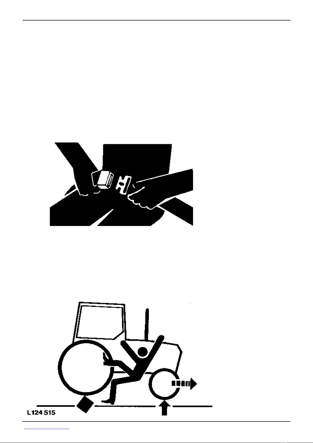
Stay Clear of Rotating Drivelines
Entanglement in rotating driveline can cause serious injury or death.
Keep all shields in place at all times. Make sure rotating shields turn freely.
Wear close-fitting clothing. Stop the engine and be sure that all rotating parts and drivelines
are stopped before making adjustments, connections, or performing any type of service on
engine or machine driven equipment.
<- Go to Section TOC
Section 10 page 4
TM110119-REPAIR TECHNICAL MANUAL
Page 13
Section 10 - GENERAL INFORMATION Group 05: Safety
Handle Fluids Safely—Avoid Fires
When you work around fuel, do not smoke or work near heaters or other fire hazards.
Store flammable fluids away from fire hazards. Do not incinerate or puncture pressurized
containers.
Make sure machine is clean of trash, grease, and debris.
Do not store oily rags; they can ignite and burn spontaneously.
Prevent Battery Explosions
Keep sparks, lighted matches, and open flame away from the top of battery. Battery gas can
explode.
<- Go to Section TOC
Section 10 page 5
TM110119-REPAIR TECHNICAL MANUAL
Page 14

Section 10 - GENERAL INFORMATION Group 05: Safety
Never check battery charge by placing a metal object across the posts. Use a volt-meter or
hydrometer.
Do not charge a frozen battery; it may explode. Warm battery to 16°C (60°F).
Prepare for Emergencies
Be prepared if a fire starts.
Keep a first aid kit and fire extinguisher handy.
Keep emergency numbers for doctors, ambulance service, hospital, and fire department near
your telephone.
Remove Paint Before Welding or Heating
<- Go to Section TOC
Section 10 page 6
TM110119-REPAIR TECHNICAL MANUAL
Page 15

Section 10 - GENERAL INFORMATION Group 05: Safety
Avoid potentially toxic fumes and dust.
Hazardous fumes can be generated when paint is heated by welding, soldering, or using a
torch.
Remove paint before heating:
Remove paint a minimum of 100 mm (4 in.) from area to be affected by heating. If paint
cannot be removed, wear an approved respirator before heating or welding.
If you sand or grind paint, avoid breathing the dust. Wear an approved respirator.
If you use solvent or paint stripper, remove stripper with soap and water before
welding. Remove solvent or paint stripper containers and other flammable material
from area. Allow fumes to disperse at least 15 minutes before welding or heating.
Do not use a chlorinated solvent in areas where welding will take place.
Do all work in an area that is well ventilated to carry toxic fumes and dust away.
Dispose of paint and solvent properly.
Avoid Heating Near Pressurized Fluid Lines
Flammable spray can be generated by heating near pressurized fluid lines, resulting in
severe burns to yourself and bystanders. Do not heat by welding, soldering, or using a torch
near pressurized fluid lines or other flammable materials. Pressurized lines can accidentally
burst when heat goes beyond the immediate flame area.
<- Go to Section TOC
Section 10 page 7
TM110119-REPAIR TECHNICAL MANUAL
Page 16

Section 10 - GENERAL INFORMATION Group 05: Safety
Handle Starting Fluid Safely
Starting fluid is highly flammable.
Keep all sparks and flame away when using it. Keep starting fluid away from batteries and
cables.
To prevent accidental discharge when storing the pressurized can, keep the cap on the
container, and store in a cool, protected location.
Do not incinerate or puncture a starting fluid container.
Avoid Hot Exhaust
<- Go to Section TOC
Section 10 page 8
TM110119-REPAIR TECHNICAL MANUAL
Page 17

Section 10 - GENERAL INFORMATION Group 05: Safety
Servicing machine or attachments with engine running can result in serious personal injury.
Avoid exposure and skin contact with hot exhaust gases and components.
Exhaust parts and streams become very hot during operation. Exhaust gases and
components reach temperatures hot enough to burn people, ignite, or melt common
materials.
<- Go to Section TOC
Section 10 page 9
TM110119-REPAIR TECHNICAL MANUAL
Page 18
Section 10 - GENERAL INFORMATION Group 05: Safety
Clean Exhaust Filter Safely
<- Go to Section TOC
Section 10 page 10
TM110119-REPAIR TECHNICAL MANUAL
Page 19
Section 10 - GENERAL INFORMATION Group 05: Safety
During exhaust filter cleaning operations, the engine may run at elevated idle and hot
temperatures for an extended period of time. Exhaust gases and exhaust filter components
reach temperatures hot enough to burn people, or ignite or melt common materials.
Keep machine away from people, animals, or structures which may be susceptible to harm or
damage from hot exhaust gases or components. Avoid potential fire or explosion hazards
from flammable materials and vapors near the exhaust. Keep exhaust outlet away from
<- Go to Section TOC
Section 10 page 11
TM110119-REPAIR TECHNICAL MANUAL
Page 20

Section 10 - GENERAL INFORMATION Group 05: Safety
people and anything that can melt, burn, or explode.
Closely monitor machine and surrounding area for smoldering debris during and after
exhaust filter cleaning.
Adding fuel while an engine is running can create a fire or explosion hazard. Always stop
engine before refueling machine and clean up any spilled fuel.
Always make sure that engine is stopped while hauling machine on a truck or trailer.
Contact with exhaust components while still hot can result in serious personal injury.
Avoid contact with these components until cooled to safe temperatures.
If service procedure requires engine to be running:
Only engage power-driven parts required by service procedure
Ensure that other people are clear of operator station and machine
Keep hands, feet, and clothing away from power-driven parts.
Always disable movement (neutral), set the parking brake or mechanism and disconnect
power to attachments or tools before leaving the operator’s station.
Shut off engine and remove key (if equipped) before leaving the machine unattended.
<- Go to Section TOC
Section 10 page 12
TM110119-REPAIR TECHNICAL MANUAL
Page 21

Section 10 - GENERAL INFORMATION Group 05: Safety
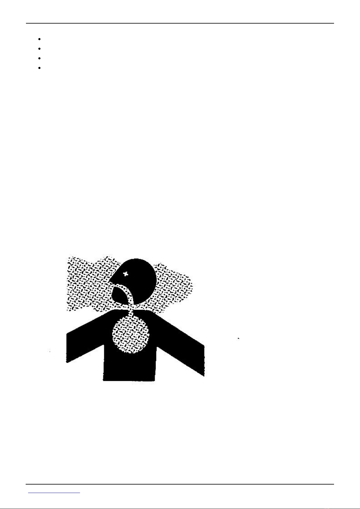
Prevent Acid Burns
Sulfuric acid in battery electrolyte is poisonous. It is strong enough to burn skin, eat holes in
clothing, and cause blindness if splashed into eyes.
Avoid the hazard by:
Filling batteries in a well-ventilated area.1.
Wearing eye protection and rubber gloves.2.
Avoiding breathing fumes when electrolyte is added.3.
Avoiding spilling or dripping electrolyte.4.
Use proper jump start procedure.5.
If you spill acid on yourself:
<- Go to Section TOC
Section 10 page 13
TM110119-REPAIR TECHNICAL MANUAL
Page 22

Section 10 - GENERAL INFORMATION Group 05: Safety
Flush your skin with water.1.
Apply baking soda or lime to help neutralize the acid.2.
Flush your eyes with water for 15—30 minutes. Get medical attention immediately.3.
If acid is swallowed:
Do not induce vomiting.1.
Drink large amounts of water or milk, but do not exceed 2 L (2 quarts).2.
Get medical attention immediately.3.
<- Go to Section TOC
Section 10 page 14
TM110119-REPAIR TECHNICAL MANUAL
Page 23

Section 10 - GENERAL INFORMATION Group 05: Safety
Handle Agricultural Chemicals Safely
Chemicals used in agricultural applications such as fungicides, herbicides, insecticides,
pesticides, rodenticides, and fertilizers can be harmful to your health or the environment if
not used carefully.
Always follow all label directions for effective, safe, and legal use of agricultural chemicals.
Reduce risk of exposure and injury:
Wear appropriate personal protective equipment as recommended by the
manufacturer. In the absence of manufacturer′s instructions, follow these general
guidelines:
Chemicals labeled′Danger′ : Most toxic. Generally require use of goggles,
respirator, gloves, and skin protection.
Chemicals labeled′Warning′ : Less toxic. Generally require use of goggles, gloves,
and skin protections.
<- Go to Section TOC
Section 10 page 15
TM110119-REPAIR TECHNICAL MANUAL
Page 24

Section 10 - GENERAL INFORMATION Group 05: Safety
Chemicals labeled′Caution′ : Least toxic. Generally require use of gloves and skin
protection.
Avoid inhaling vapor, aerosol or dust.
Always have soap, water, and towel available when working with chemicals. If chemical
contacts skin, hands, or face, wash immediately with soap and water. If chemical gets
into eyes, flush immediately with water.
Wash hands and face after using chemicals and before eating, drinking, smoking, or
urination.
Do not smoke or eat while applying chemicals.
After handling chemicals, always bathe or shower and change clothes. Wash clothing
before wearing again.
Seek medical attention immediately if illness occurs during or shortly after use of
chemicals.
Keep chemicals in original containers. Do not transfer chemicals to unmarked
containers or to containers used for food or drink.
Store chemicals in a secure, locked area away from human or livestock food. Keep
children away.
Always dispose of containers properly. Triple rinse empty containers and puncture or
crush containers and dispose of properly.
Clean Vehicle of Hazardous Pesticides
CAUTION:
During application of hazardous pesticides, pesticide residue can build up
on the inside or outside of the vehicle. Clean vehicle according to use
instructions of hazardous pesticides.
When exposed to hazardous pesticides, clean exterior and interior of vehicle daily to keep
free of the accumulation of visible dirt and contamination.
[1] - Sweep or vacuum the floor of cab.
[2] - Clean headliners and inside cowlings of cab.
[3] - Wash entire exterior of vehicle.
[4] - Dispose of any wash water with hazardous concentrations of active or non-active
ingredients according to published regulations or directives.
<- Go to Section TOC
Section 10 page 16
TM110119-REPAIR TECHNICAL MANUAL
Page 25

Section 10 - GENERAL INFORMATION Group 05: Safety
Handling Batteries Safely
<- Go to Section TOC
Section 10 page 17
TM110119-REPAIR TECHNICAL MANUAL
Page 26

Section 10 - GENERAL INFORMATION Group 05: Safety
Battery gas can explode. Keep sparks and flames away from batteries. Use a flashlight to
check battery electrolyte level.
Never check battery charge by placing a metal object across the posts. Use a voltmeter or
hydrometer.
Always remove grounded (-) battery clamp first and replace grounded clamp last.
Sulfuric acid in battery electrolyte is poisonous and strong enough to burn skin, eat holes in
clothing, and cause blindness if splashed into eyes.
Avoid hazards by:
Filling batteries in a well-ventilated area
Wearing eye protection and rubber gloves
<- Go to Section TOC
Section 10 page 18
TM110119-REPAIR TECHNICAL MANUAL
Page 27
Section 10 - GENERAL INFORMATION Group 05: Safety
Avoiding use of air pressure to clean batteries
Avoiding breathing fumes when electrolyte is added
Avoiding spilling or dripping electrolyte
Using correct battery booster or charger procedure.
If acid is spilled on skin or in eyes:
Flush skin with water.1.
Apply baking soda or lime to help neutralize the acid.2.
Flush eyes with water for 15—30 minutes. Get medical attention immediately.3.
If acid is swallowed:
Do not induce vomiting.1.
Drink large amounts of water or milk, but do not exceed 2 L (2 qt.).2.
Get medical attention immediately.3.
WARNING: Battery posts, terminals, and related accessories contain lead and lead
compounds, chemicals known to the State of California to cause cancer and reproductive
harm.Wash hands after handling.
Avoid Harmful Asbestos Dust
Avoid breathing dust that may be generated when handling components containing asbestos
fibers. Inhaled asbestos fibers may cause lung cancer.
Components in products that may contain asbestos fibers are brake pads, brake band and
lining assemblies, clutch plates, and some gaskets. The asbestos used in these components
is usually found in a resin or sealed in some way. Normal handling is not hazardous as long as
airborne dust containing asbestos is not generated.
Avoid creating dust. Never use compressed air for cleaning. Avoid brushing or grinding
<- Go to Section TOC
Section 10 page 19
TM110119-REPAIR TECHNICAL MANUAL
Page 28

Section 10 - GENERAL INFORMATION Group 05: Safety
material containing asbestos. When servicing, wear an approved respirator. A special vacuum
cleaner is recommended to clean asbestos. If not available, apply a mist of oil or water on the
material containing asbestos.
Keep bystanders away from the area.
Dispose of Waste Properly
Improperly disposing of waste can threaten the environment and ecology. Potentially harmful
waste used with John Deere equipment include such items as oil, fuel, coolant, brake fluid,
filters, and batteries.
Use leakproof containers when draining fluids. Do not use food or beverage containers that
may mislead someone into drinking from them.
Do not pour waste onto the ground, down a drain, or into any water source.
Air conditioning refrigerants escaping into the air can damage the Earth’s atmosphere.
Government regulations may require a certified air conditioning service center to recover and
recycle used air conditioning refrigerants.
Inquire on the proper way to recycle or dispose of waste from your local environmental or
recycling center, or from your John Deere dealer.
<- Go to Section TOC
Section 10 page 20
TM110119-REPAIR TECHNICAL MANUAL
Page 29

Section 10 - GENERAL INFORMATION Group 05: Safety
Avoid High-Pressure Fluids
Inspect hydraulic hoses periodically – at least once per year – for leakage, kinking, cuts,
cracks, abrasion, blisters, corrosion, exposed wire braid or any other signs of wear or
damage.
Replace worn or damaged hose assemblies immediately with John Deere approved
replacement parts.
Escaping fluid under pressure can penetrate the skin causing serious injury.
Avoid the hazard by relieving pressure before disconnecting hydraulic or other lines. Tighten
all connections before applying pressure.
Search for leaks with a piece of cardboard. Protect hands and body from high-pressure fluids.
If an accident occurs, see a doctor immediately. Any fluid injected into the skin must be
surgically removed within a few hours or gangrene may result. Doctors unfamiliar with this
type of injury should reference a knowledgeable medical source. Such information is
available in English from Deere & Company Medical Department in Moline, Illinois, U.S.A., by
calling 1-800-822-8262 or +1 309-748-5636.
Wait Before Opening High-Pressure Fuel System
<- Go to Section TOC
Section 10 page 21
TM110119-REPAIR TECHNICAL MANUAL
Page 30

Section 10 - GENERAL INFORMATION Group 05: Safety
High-pressure fluid remaining in fuel lines can cause serious injury. Only technicians familiar
with this type of system should perform repairs. Before disconnecting fuel lines, sensors, or
any other components between the high-pressure fuel pump and nozzles on engines with
High Pressure Common Rail (HPCR) fuel system, wait a minimum of 15 minutes after engine
is stopped.
Service Accumulator Systems Safely
Escaping fluid or gas from systems with pressurized accumulators that are used in air
conditioning, hydraulic, and air brake systems can cause serious injury. Extreme heat can
cause the accumulator to burst, and pressurized lines can be accidentally cut. Do not weld or
use a torch near a pressurized accumulator or pressurized line.
Relieve pressure from the pressurized system before removing accumulator.
Relieve pressure from the hydraulic system before removing accumulator. Never attempt to
<- Go to Section TOC
Section 10 page 22
TM110119-REPAIR TECHNICAL MANUAL
Page 31
Section 10 - GENERAL INFORMATION Group 05: Safety
relieve hydraulic system or accumulator pressure by loosening a fitting.
Accumulators cannot be repaired.
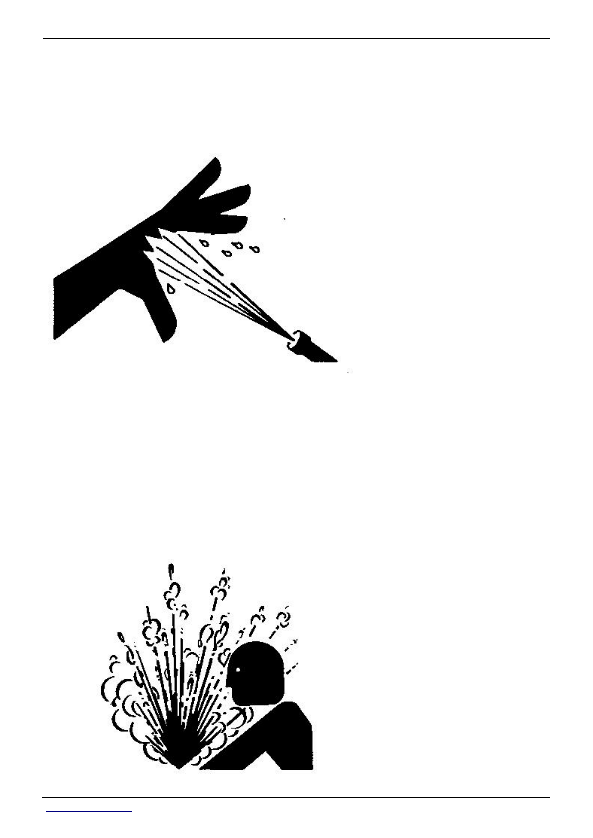
Protect Against High Pressure Spray
Spray from high pressure nozzles can penetrate the skin and cause serious injury. Keep spray
from contacting hands or body.
If an accident occurs, see a doctor immediately. Any high pressure spray injected into the
skin must be surgically removed within a few hours or gangrene may result. Doctors
unfamiliar with this type of injury should reference a knowledgeable medical source. Such
information is available from Deere & Company Medical Department in Moline, Illinois, U.S.A.
Service Cooling System Safely
<- Go to Section TOC
Section 10 page 23
TM110119-REPAIR TECHNICAL MANUAL
Page 32

Section 10 - GENERAL INFORMATION Group 05: Safety
Explosive release of fluids from pressurized cooling system can cause serious burns.
Shut off engine. Only remove filler cap when cool enough to touch with bare hands. Slowly
loosen cap to first stop to relieve pressure before removing completely.
Prevent Machine Runaway
Avoid possible injury or death from machinery runaway.
Do not start engine by shorting across starter terminals. Machine will start in gear if normal
circuitry is bypassed.
NEVER start engine while standing on ground. Start engine only from operator’s seat, with
transmission in neutral or park.
Keep ROPS Installed Properly
<- Go to Section TOC
Section 10 page 24
TM110119-REPAIR TECHNICAL MANUAL
Page 33

Section 10 - GENERAL INFORMATION Group 05: Safety
Make certain all parts are reinstalled correctly if the roll-over protective structure (ROPS) is
loosened or removed for any reason. Tighten mounting bolts to proper torque.
The protection offered by ROPS will be impaired if ROPS is subjected to structural damage, is
involved in an overturn incident, or is in any way altered by welding, bending, drilling, or
cutting. A damaged ROPS should be replaced, not reused.
The seat is part of the ROPS safety zone. Replace only with John Deere seat approved for
your tractor.
Any alteration of the ROPS must be approved by the manufacturer.
Avoid Backover Accidents
Before moving machine, be sure that all persons are clear of machine path. Turn around and
look directly for best visibility. Use a signal person when backing if view is obstructed or when
in close quarters.
Do not rely on a camera to determine if personnel or obstacles are behind the machine. The
system can be limited by many factors including maintenance practices, environmental
conditions, and operating range.
Park Machine Safely
<- Go to Section TOC
Section 10 page 25
TM110119-REPAIR TECHNICAL MANUAL
Page 34

Section 10 - GENERAL INFORMATION Group 05: Safety
Before working on the machine:
Lower all equipment to the ground.
Stop the engine and remove the key.
Disconnect the battery ground strap.
Hang a "DO NOT OPERATE" tag in operator station.
Support Machine Properly
Always lower the attachment or implement to the ground before you work on the machine. If
the work requires that the machine or attachment be lifted, provide secure support for them.
If left in a raised position, hydraulically supported devices can settle or leak down.
Do not support the machine on cinder blocks, hollow tiles, or props that may crumble under
continuous load. Do not work under a machine that is supported solely by a jack. Follow
recommended procedures in this manual.
<- Go to Section TOC
Section 10 page 26
TM110119-REPAIR TECHNICAL MANUAL
Page 35

Section 10 - GENERAL INFORMATION Group 05: Safety
When implements or attachments are used with a machine, always follow safety precautions
listed in the implement or attachment operator′s manual.
Work in Clean Area
Before starting a job:
Clean work area and machine.
Make sure you have all necessary tools to do your job.
Have the right parts on hand.
Read all instructions thoroughly; do not attempt shortcuts.
Work In Ventilated Area
Engine exhaust fumes can cause sickness or death. If it is necessary to run an engine in an
enclosed area, remove the exhaust fumes from the area with an exhaust pipe extension.
<- Go to Section TOC
Section 10 page 27
TM110119-REPAIR TECHNICAL MANUAL
Page 36
Section 10 - GENERAL INFORMATION Group 05: Safety
If you do not have an exhaust pipe extension, open the doors and get outside air into the
area.
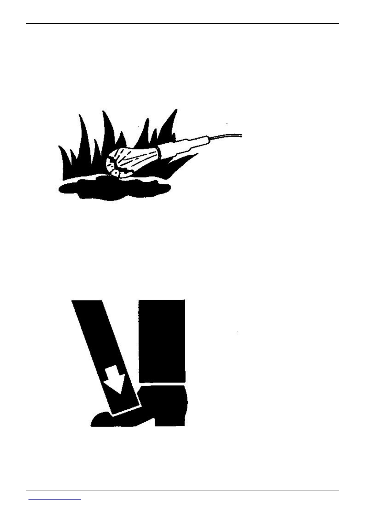
Illuminate Work Area Safely
Illuminate your work area adequately but safely. Use a portable safety light for working inside
or under the machine. Make sure the bulb is enclosed by a wire cage. The hot filament of an
accidentally broken bulb can ignite spilled fuel or oil.
Use Proper Lifting Equipment
Lifting heavy components incorrectly can cause severe injury or machine damage.
Follow recommended procedure for removal and installation of components in the manual.
<- Go to Section TOC
Section 10 page 28
TM110119-REPAIR TECHNICAL MANUAL
Page 37
Section 10 - GENERAL INFORMATION Group 05: Safety
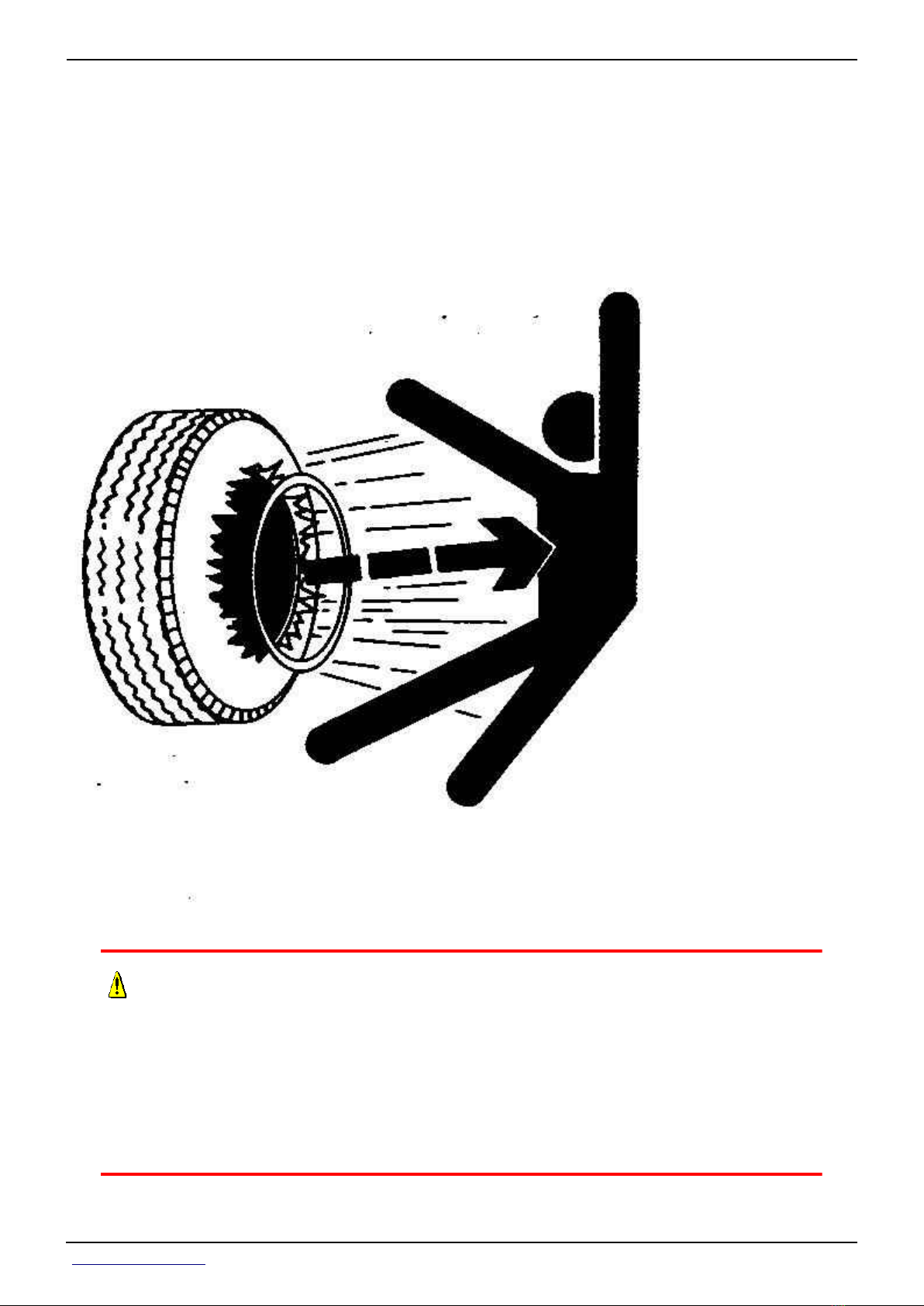
Service Tires Safely
CAUTION:
Explosive separation of a tire and rim parts can cause serious injury or
death.
Do not attempt to mount a tire unless you have the proper equipment and
experience to perform the job.
Always maintain the correct tire pressure. Do not inflate the tires above the recommended
<- Go to Section TOC
Section 10 page 29
TM110119-REPAIR TECHNICAL MANUAL
Page 38
Section 10 - GENERAL INFORMATION Group 05: Safety
pressure.
Never weld or heat a wheel and tire assembly. The heat can cause an increase in air pressure
resulting in a tire explosion. Welding can structurally weaken or deform the wheel.
When inflating tires, use a clip-on chuck and extension hose long enough to allow you to
stand to one side and NOT in front of or over the tire assembly. Use a safety cage if available.
Check wheels for low pressure, cuts, bubbles, damaged rims or missing lug bolts and nuts.
Instructional Seat
The instructional seat, if so equipped, has been provided only for training operators or
diagnosing machine problems.
Service Front-Wheel Drive Tractor Safely
<- Go to Section TOC
Section 10 page 30
TM110119-REPAIR TECHNICAL MANUAL
Page 39

Section 10 - GENERAL INFORMATION Group 05: Safety
When servicing front-wheel drive tractor with the rear wheels supported off the ground and
rotating wheels by engine power, always support front wheels in a similar manner. Loss of
electrical power or transmission hydraulic system pressure will engage the front driving
wheels, pulling the rear wheels off the support if front wheels are not raised. Under these
conditions, front drive wheels can engage even with switch in disengaged position.
Use Steps and Handholds Correctly
Prevent falls by facing the machine when getting on and off. Maintain 3-point contact with
steps, handholds, and handrails.
Use extra care when mud, snow, or moisture present slippery conditions. Keep steps clean
and free of grease or oil. Never jump when exiting machine. Never mount or dismount a
moving machine.
Transport Tractor Safely
A disabled tractor is best transported on a flatbed carrier. Use chains to secure the tractor to
the carrier. The axles and tractor frame are suitable attachment points.
<- Go to Section TOC
Section 10 page 31
TM110119-REPAIR TECHNICAL MANUAL
Page 40

Section 10 - GENERAL INFORMATION Group 05: Safety
Before transporting the tractor on a low-loader truck or flatbed rail wagon, make sure that
the hood is secured over the tractor engine and that doors, roof hatch (if equipped) and
windows are properly closed.
Never tow a tractor at a speed greater than 10 km/h (6 mph). An operator must steer and
brake the tractor under tow.
Practice Safe Maintenance
Understand service procedure before doing work. Keep area clean and dry.
Never lubricate, service, or adjust machine while it is moving. Keep hands, feet , and clothing
from power-driven parts. Disengage all power and operate controls to relieve pressure. Lower
equipment to the ground. Stop the engine. Remove the key. Allow machine to cool.
<- Go to Section TOC
Section 10 page 32
TM110119-REPAIR TECHNICAL MANUAL
Page 41

Section 10 - GENERAL INFORMATION Group 05: Safety
Securely support any machine elements that must be raised for service work.
Keep all parts in good condition and properly installed. Fix damage immediately. Replace
worn or broken parts. Remove any buildup of grease, oil, or debris.
On self-propelled equipment, disconnect battery ground cable (-) before making adjustments
on electrical systems or welding on machine.
On towed implements, disconnect wiring harnesses from tractor before servicing electrical
system components or welding on machine.
Use Proper Tools
Use tools appropriate to the work. Makeshift tools and procedures can create safety hazards.
Use power tools only to loosen threaded parts and fasteners.
For loosening and tightening hardware, use the correct size tools. DO NOT use U.S.
measurement tools on metric fasteners. Avoid bodily injury caused by slipping wrenches.
Use only service parts meeting John Deere specifications.
Construct Dealer-Made Tools Safely
<- Go to Section TOC
Section 10 page 33
TM110119-REPAIR TECHNICAL MANUAL
Page 42

Section 10 - GENERAL INFORMATION Group 05: Safety
Faulty or broken tools can result in serious injury. When constructing tools, use proper,
quality materials, and good workmanship.
Do not weld tools unless you have the proper equipment and experience to perform the job.
Replace Safety Signs
Replace missing or damaged safety signs. See the machine operator’s manual for correct
safety sign placement.
Install All Guards
<- Go to Section TOC
Section 10 page 34
TM110119-REPAIR TECHNICAL MANUAL
Page 43

Section 10 - GENERAL INFORMATION Group 10: General Information
Rotating cooling system fans, belts, pulleys, and drives can cause serious injury.
Keep all guards in place at all times during engine operation.
Wear close-fitting clothes. Stop the engine and be sure fans, belts, pulleys, and drives are
stopped before making adjustments, connections, or cleaning near fans and their drive
components.
Live With Safety
Before returning machine to customer, make sure machine is functioning properly, especially
the safety systems. Install all guards and shields.
<- Go to Section TOC
Section 10 page 35
TM110119-REPAIR TECHNICAL MANUAL
Page 44

Section 10 - GENERAL INFORMATION Group 10: General Information
Group 10 - General Information
List of References
Below is a list of all items within this group.
Trademarks
Sealants and Adhesives Cross-Reference Chart
Metric Bolt and Screw Torque Values
Unified Inch Bolt and Screw Torque Values
Face Seal Fittings Assembly and Installation—All Pressure Applications
Metric Face Seal And O-Ring Stud End Fitting Torque Chart—Standard Pressures
Metric Face Seal and O-Ring Stud End Fitting Torque Chart—High Pressure Applications
SAE Face Seal and O-Ring Stud End Fitting Torque Chart—Standard Pressures
SAE Face Seal and O-Ring Stud End Fitting Torque Chart—High Pressure Applications
Four Bolt Flange Fittings Assembly and Installation—All Pressure Applications
SAE Four Bolt Flange Cap Screw Torque Values—Standard Pressure Applications
SAE Four Bolt Flange Cap Screw Torque Values—High Pressure Applications
External Hexagon Port Plug Torque Chart
Prevent Hydraulic System Contamination
Check Oil Lines and Fittings
Basic Electrical Component Handling / Precautions For Vehicles Equipped With Computer
Controlled Systems
Identify Zinc-Flake Coated Fasteners
Use Torque Wrench Adapter
Servicing and Connecting Snap to Connect STC™ Fittings
Glossary of Terms
<- Go to Section TOC
Section 10 page 36
TM110119-REPAIR TECHNICAL MANUAL
Page 45

Section 10 - GENERAL INFORMATION Group 10: General Information
Trademarks
Trademarks
AccuDepth™ Trademark of Deere and Company
ACS™ Trademark of Deere and Company
ActiveSeat™ Trademark of Deere and Company
AMBLYGON™ Trademark of Kluber Lubrication
AMPSEAL 16™ Trademark of Tyco Electronics
AutoLoad™ Trademark of Deere and Company
AutoPowr™ Trademark of Deere and Company
AutoPowr™/IVT™ Trademark of Deere and Company
AutoQuad™ II Trademark of Deere and Company
AutoQuad™ PLUS Trademark of Deere and Company
AutoTrac™ Trademark of Deere and Company
Avdel™ Trademark of Avdel UK Limited
Bio Hy-Guard™ Trademark of Deere and Company
Break-In™ Trademark of Deere and Company
Break-In PLUS™ Trademark of Deere and Company
CINCH™ Trademark of Cinch Inc.
ClimaTrak™ Trademark of Deere and Company
ComfortCommand™ Trademark of Deere and Company
ComfortGard™ Trademark of Deere and Company
ComfortGard Deluxe™ Trademark of Deere and Company
CommandARM™ Trademark of Deere and Company
CommandCenter™ Trademark of Deere and Company
CommandQuad™ Trademark of Deere and Company
CommandView™ Trademark of Deere and Company
COOL-GUARD™ II Trademark of Deere and Company
CoolScan™ Trademark of Deere and Company
CPC™ Trademark of AMP Incorporated
Deere™ Trademark of Deere and Company
DEUTSCH™ Trademark of Deutsch Company
DURABUILT™ Trademark of Camoplast Inc.
Efficiency Manager™ Trademark of Deere and Company
FieldCruise™ Trademark of Deere and Company
Field Doc™ Trademark of Deere and Company
Field Office™ Trademark of Deere and Company
<- Go to Section TOC
Section 10 page 37
TM110119-REPAIR TECHNICAL MANUAL
Page 46

Section 10 - GENERAL INFORMATION Group 10: General Information
Trademarks
GreenStar™ Trademark of Deere and Company
HY-GARD™ Trademark of Deere and Company
ILS™ Trademark of Deere and Company
iPhone® Trademark of Apple, Inc.
iPod® Trademark of Apple, Inc.
iPod Touch® Trademark of Apple, Inc.
iTEC™ Trademark of Deere and Company
iTEC™ Pro Trademark of Deere and Company
IVT™ Trademark of Deere and Company
IVT Selector™ Trademark of Deere and Company
JDLink™ Trademark of Deere and Company
JDOffice™ Trademark of Deere and Company
John Deere™ Trademark of Deere and Company
Loctite™ Trademark of Henkel Corporation
MATE-N-LOC™ Trademark of AMP Incorporated
METRIMATE™ Trademark of AMP Incorporated
METRI-PACK™ Trademark of Delphi Packard Electric Systems
NEVER-SEEZ™ Trademark of Bostik-Findley Inc.
Oilscan™ Trademark of Deere and Company
Parallel Tracking™ Trademark of Deere and Company
PLUS-50™ II Trademark of Deere and Company
PowrQuad™ Trademark of Deere and Company
PowrQuad™ PLUS Trademark of Deere and Company
PowerTech™ Trademark of Deere and Company
PowerTech™ Plus Trademark of Deere and Company
Power Zero™ Trademark of Deere and Company
QUICK METAL™ Trademark of Henkel Corporation
QuickTatch™ Trademark of Deere and Company
Row-Trak™ Trademark of Deere and Company
ServiceADVISOR™ Trademark of Deere and Company
SERVICEGARD™ Trademark of Deere and Company
StarFire™ Trademark of Deere and Company
StarFire™ iTC Trademark of Deere and Company
STC™ Trademark of Aeroquip Corporation
StellarSupport™ Trademark of Deere and Company
SUMITOMO™ Trademark of Sumitomo Corporation
<- Go to Section TOC
Section 10 page 38
TM110119-REPAIR TECHNICAL MANUAL
Page 47

Section 10 - GENERAL INFORMATION Group 10: General Information
Trademarks
TEFLON™ Trademark of DuPont Co.
TIA™ Trademark of Deere and Company
TLS™ Trademark of Deere and Company
TLS™ Plus Trademark of Deere and Company
TouchSet™ Trademark of Deere and Company
Tractor-Implement Automation™ Trademark of Deere and Company
Vari-Cool™ Trademark of Deere and Company
Weather Pack™ Trademark of Packard Electric
YAZAKI™ Trademark of Yazaki Corporation
<- Go to Section TOC
Section 10 page 39
TM110119-REPAIR TECHNICAL MANUAL
Page 48

Section 10 - GENERAL INFORMATION Group 10: General Information
Sealants and Adhesives Cross-Reference Chart
<- Go to Section TOC
Section 10 page 40
TM110119-REPAIR TECHNICAL MANUAL
Page 49

Section 10 - GENERAL INFORMATION Group 10: General Information
U.S. Part Number
Bonding
PM37513 PM38606 BLACK AND WHITE 4 g Epoxy Adhesive 21425
PM37391 PM38615 CLEAR 2 g Gel Super Glue 454
PM37532 — BLACK 5 oz Weatherstrip Adhesive 30540
— PM38603 YELLOW 147 ml Weatherstrip Adhesive 30537
Gasketing
PM38655 PM38625 PURPLE 50 ml Flexible Form-in-Place Gasket 515
— PM38600 BROWN 118 ml Liquid Gasket Maker 30524
PM37559 PM38600 BROWN 4 oz
PM38657 PM38628 BLUE 50 ml High-Flex Form-in-Place Gasket 17430
PM37463 PM37463 CLEAR 80 g RTV Clear Silicone 59530
PM37521 CLEAR 30 g RTV Clear Silicone 59575
— PM38618 CLEAR 300 g RTV Clear Silicone
PM37465 PM38616 METALLIC BLUE 80 ml Ultra Blue RTV Silicone 58730
PM37553 PM37553 BURGUNDY 16 oz High Tack Gasket Dressing 30525
PM37555 PM38607 BURGUNDY 9 oz aerosol Hi-Tack Gasket Sealant 30524
PM37469 PM38609 RED 80 g Hi-Temp RTV Silicone 59630
PM37529 — RED 7.25 aerosol Hi-Temp RTV Silicone 30541
PM37512 PM37512 — — Flexible Flange Sealant 5900
PM37616 — — 20 g Stick Copper Anti-Seize Stick —
PM37617 — — 20 g Stick Silver-Grade Anti-Seize Stick —
TY24810 TY24810 — 12.5 aerosol NEVER-SEEZ ™ —
TY24811 TY24811 — 8 oz can with brush NEVER-SEEZ ™ —
H154379 — GREEN Sealant —
Canadian Part
Number
Color Size Description
General Purpose Gasket Dressing (Aviation Gasket
Sealant)
LOCTITE ™
/Permatex Number
30517
Priming
PM37509 PM38611 GREEN 4.5 oz Cure Primer 7649
Retaining
PM38651 PM38612 SILVER 50 ml QUICK METAL ™ 660
PM37485 — GREEN 36 ml Maximum Strength 680
— PM38626 GREEN 50 ml Maximum Strength 62083
PM38652 — GREEN 36 ml High-Temperature 620
Thread Locking and Sealing
PM38653 — PURPLE 6 ml Low Strength 222
— PM38645 PURPLE 2 g Superglue Instant Adhesive 22200
PM37418 PM38621 BLUE 6 ml Medium Strength 242
PM37477 PM38622 BLUE 36 ml Medium Strength 242
PM37643 — BLUE 9 g Stick Blue Stick Threadlocker (medium-strength) —
PM37614 — BLUE 19 g Stick Blue Stick Threadlocker (medium-strength) —
PM37615 — — 19 g Stick PST Thread Sealant Stick —
PM37421 PM38623 RED 6 ml High Strength
PM38654 PM38623 RED 36 ml High Strength 271
— PM38624 RED 50 ml High Strength 27140
PM38656 PM38627 RED 36 ml High Strength 277
PM37700 — RED 19 g Stick Red Stick Threadlocker (High-Strength) —
PM37701 — RED 9 g Stick Red Stick Threadlocker (High-Strength) —
PM37398 PM38613 WHITE 6 ml Pipe Sealant with TEFLON ™ 592
PM37397 PM38613 WHITE 50 ml Pipe Sealant with TEFLON 592
271 (usually red in
color)
<- Go to Section TOC
Section 10 page 41
TM110119-REPAIR TECHNICAL MANUAL
Page 50

Section 10 - GENERAL INFORMATION Group 10: General Information
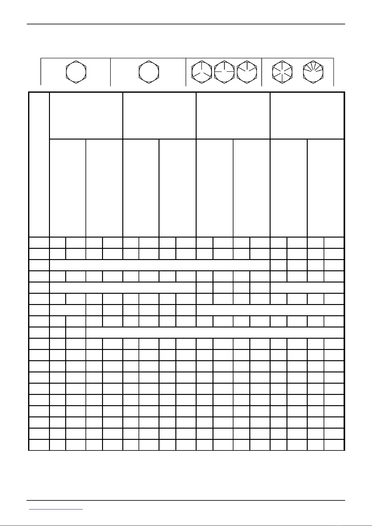
Metric Bolt and Screw Torque Values
Class 4.8 Class 8.8 or 9.8 Class 10.9 Class 12.9
Bolt
or
Screw
Size
Lubricated
[ “Lubricated”
means coated
with a
lubricant such
as engine oil,
fasteners with
phosphate
and oil
coatings, or
M20 and
larger
fasteners with
JDM F13C,
F13F or F13J
zinc flake
coating. ]
Dry
[ “Dry” means
plain or zinc
plated without
any
lubrication, or
M6 to M18
fasteners with
JDM F13B,
F13E or F13H
zinc flake
coating. ]
N˙m lb.-in. N˙m lb.-in. N˙m lb.-in. N˙m lb.-in. N˙m lb.-in. N˙m lb.-in. N˙m lb.-in. N˙m lb.-in.
M6 4.7 42 6 53 8.9 79 11.3 100 13 115 16.5 146 15.5 137 19.5 172
N˙m lb.-ft. N˙m lb.-ft. N˙m lb.-ft. N˙m lb.-ft.
M8 11.5 102 14.5 128 22 194 27.5 243 32 23.5 40 29.5 37 27.5 47 35
N˙m lb.-ft. N˙m lb.-ft. N˙m lb.-ft.
M10 23 204 29 21 43 32 55 40 63 46 80 59 75 55 95 70
N˙m lb.-ft.
M12 40 29.5 50 37 75 55 95 70 110 80 140 105 130 95 165 120
M14 63 46 80 59 120 88 150 110 175 130 220 165 205 150 260 190
M16 100 74 125 92 190 140 240 175 275 200 350 255 320 235 400 300
M18 135 100 170 125 265 195 330 245 375 275 475 350 440 325 560 410
M20 190 140 245 180 375 275 475 350 530 390 675 500 625 460 790 580
M22 265 195 330 245 510 375 650 480 725 535 920 680 850 625 1080 800
M24 330 245 425 315 650 480 820 600 920 680 1150 850 1080 800 1350 1000
M27 490 360 625 460 950 700 1200 885 1350 1000 1700 1250 1580 1160 2000 1475
M30 660 490 850 625 1290 950 1630 1200 1850 1350 2300 1700 2140 1580 2700 2000
M33 900 665 1150 850 1750 1300 2200 1625 2500 1850 3150 2325 2900 2150 3700 2730
M36 1150 850 1450 1075 2250 1650 2850 2100 3200 2350 4050 3000 3750 2770 4750 3500
Torque values listed are for general use only, based on the
strength of the bolt or screw. DO NOT use these values if a
different torque value or tightening procedure is given for a
specific application. For stainless steel fasteners or for nuts
on U-bolts, see the tightening instructions for the specific
application. Tighten plastic insert or crimped steel type lock
nuts by turning the nut to the dry torque shown in the chart,
unless different instructions are given for the specific
application.
Shear bolts are designed to fail under predetermined loads. Always
replace shear bolts with identical property class. Replace fasteners
with the same or higher property class. If higher property class
fasteners are used, tighten these to the strength of the original. Make
sure fastener threads are clean and that you properly start thread
engagement. When possible, lubricate plain or zinc plated fasteners
other than lock nuts, wheel bolts or wheel nuts, unless different
instructions are given for the specific application.
<- Go to Section TOC
Section 10 page 42
TM110119-REPAIR TECHNICAL MANUAL
Page 51
Section 10 - GENERAL INFORMATION Group 10: General Information
Unified Inch Bolt and Screw Torque Values
SAE Grade 2
[ Grade 2 applies for hex cap
screws (not hex bolts) up to 6
SAE Grade 1
in. (152 mm) long. Grade 1
applies for hex cap screws
over 6 in. (152 mm) long, and
for all other types of bolts and
screws of any length. ]
SAE Grade 5, 5.1 or 5.2 SAE Grade 8 or 8.2
Bolt
or
Screw
Size
Lubricated
[
“Lubricated”
means coated
with a
lubricant such
as engine oil,
fasteners with
phosphate
and oil
coatings, or
7/8 in. and
larger
fasteners with
JDM F13C,
F13F or F13J
zinc flake
coating. ]
Dry
[ “Dry” means
plain or zinc
plated without
any
lubrication, or
1/4 to 3/4 in.
fasteners with
JDM F13B,
F13E or F13H
zinc flake
coating. ]
Lubricated
[ “Lubricated”
means coated
with a
lubricant such
as engine oil,
fasteners with
phosphate
and oil
coatings, or
7/8 in. and
larger
fasteners with
JDM F13C,
F13F or F13J
zinc flake
coating. ]
Dry
[ “Dry” means
plain or zinc
plated without
any
lubrication, or
1/4 to 3/4 in.
fasteners with
JDM F13B,
F13E or F13H
zinc flake
coating. ]
N˙m lb.-in. N˙m lb.-in. N˙m lb.-in. N˙m lb.-in. N˙m lb.-in. N˙m lb.-in. N˙m lb.-in. N˙m lb.-in.
1/4 3.7 33 4.7 42 6 53 7.5 66 9.5 84 12 106 13.5 120 17 150
N˙m lb.-ft. N˙m lb.-ft.
5/16 7.7 68 9.8 86 12 106 15.5 137 19.5 172 25 221 28 20.5 35 26
N˙m lb.-ft. N˙m lb.-ft.
3/8 13.5 120 17.5 155 22 194 27 240 35 26 44 32.5 49 36 63 46
N˙m lb.-ft. N˙m lb.-ft. N˙m lb.-ft.
7/16 22 194 28 20.5 35 26 44 32.5 56 41 70 52 80 59 100 74
N˙m lb.-ft.
1/2 34 25 42 31 53 39 67 49 85 63 110 80 120 88 155 115
9/16 48 35.5 60 45 76 56 95 70 125 92 155 115 175 130 220 165
5/8 67 49 85 63 105 77 135 100 170 125 215 160 240 175 305 225
3/4 120 88 150 110 190 140 240 175 300 220 380 280 425 315 540 400
7/8 190 140 240 175 190 140 240 175 490 360 615 455 690 510 870 640
1 285 210 360 265 285 210 360 265 730 540 920 680 1030 760 1300 960
1-1/8 400 300 510 375 400 300 510 375 910 670 1150 850 1450 1075 1850 1350
1-1/4 570 420 725 535 570 420 725 535 1280 945 1630 1200 2050 1500 2600 1920
1-3/8 750 550 950 700 750 550 950 700 1700 1250 2140 1580 2700 2000 3400 2500
1-1/2 990 730 1250 930 990 730 1250 930 2250 1650 2850 2100 3600 2650 4550 3350
<- Go to Section TOC
Section 10 page 43
TM110119-REPAIR TECHNICAL MANUAL
Page 52

Section 10 - GENERAL INFORMATION Group 10: General Information
SAE Grade 2
[ Grade 2 applies for hex cap
screws (not hex bolts) up to 6
SAE Grade 1
in. (152 mm) long. Grade 1
applies for hex cap screws
over 6 in. (152 mm) long, and
for all other types of bolts and
screws of any length. ]
SAE Grade 5, 5.1 or 5.2 SAE Grade 8 or 8.2
Bolt
or
Screw
Size
Lubricated
[
“Lubricated”
means coated
with a
lubricant such
as engine oil,
fasteners with
phosphate
and oil
coatings, or
7/8 in. and
larger
fasteners with
JDM F13C,
F13F or F13J
zinc flake
coating. ]
Dry
[ “Dry” means
plain or zinc
plated without
any
lubrication, or
1/4 to 3/4 in.
fasteners with
JDM F13B,
F13E or F13H
zinc flake
coating. ]
Lubricated
[
“Lubricated”
means coated
with a
lubricant such
as engine oil,
fasteners with
phosphate
and oil
coatings, or
7/8 in. and
larger
fasteners with
JDM F13C,
F13F or F13J
zinc flake
coating. ]
Dry
[ “Dry” means
plain or zinc
plated without
any
lubrication, or
1/4 to 3/4 in.
fasteners with
JDM F13B,
F13E or F13H
zinc flake
coating. ]
Torque values listed are for general use only, based on the strength
of the bolt or screw. DO NOT use these values if a different torque
value or tightening procedure is given for a specific application. For
plastic insert or crimped steel type lock nuts, for stainless steel
fasteners, or for nuts on U-bolts, see the tightening instructions for
the specific application. Shear bolts are designed to fail under
predetermined loads. Always replace shear bolts with identical grade.
Lubricated
[ “Lubricated”
means coated
with a
lubricant such
as engine oil,
fasteners with
phosphate
and oil
coatings, or
7/8 in. and
larger
fasteners with
JDM F13C,
F13F or F13J
zinc flake
coating. ]
Dry
[ “Dry” means
plain or zinc
plated without
any
lubrication, or
1/4 to 3/4 in.
fasteners with
JDM F13B,
F13E or F13H
zinc flake
coating. ]
Replace fasteners with the same or higher grade. If higher
grade fasteners are used, tighten these to the strength of the
original. Make sure fastener threads are clean and that you
properly start thread engagement. When possible, lubricate
plain or zinc plated fasteners other than lock nuts, wheel
bolts or wheel nuts, unless different instructions are given for
the specific application.
<- Go to Section TOC
Section 10 page 44
TM110119-REPAIR TECHNICAL MANUAL
Page 53

Section 10 - GENERAL INFORMATION Group 10: General Information
Face Seal Fittings Assembly and Installation—All
Pressure Applications
Face Seal O-Ring to Stud End Installation
[1] - Inspect the fitting surfaces. They must be free of dirt and/or defects.
[2] - Inspect the O-ring. It must be free of damage and/or defects.
[3] - Lubricate O-rings and install into groove using petroleum jelly to hold in place.
[4] - Push O-ring into groove with petroleum jelly so O-ring is not displaced during assembly.
[5] - Index angle fittings and tighten by hand pressing joint together to insure O-ring remains
in place.
[6] - Tighten fitting or nut to torque value shown on the chart per dash size stamped on the
fitting. DO NOT allow hoses to twist when tightening fittings.
Face Seal Adjustable Stud End O-Ring Installation
[1] - Back off lock nut (jam nut) and washer to full exposed turned down section of the
fitting.
[2] - Install a thimble over the fitting threads to protect the O-ring from nicks.
[3] - Slide the O-ring over the thimble into the turned down section of the fitting.
[4] - Remove thimble.
Face Seal Straight Stud End O-Ring Installation
[1] - Install a thimble over the fitting threads to protect the O-ring from nicks.
[2] - Slide the O-ring over the thimble into the turned down section of the fitting.
[3] - Remove thimble.
Fitting Installation
[1] - Install fitting by hand until snug.
[2] - Position adjustable fittings by unscrewing the fitting no more than one turn.
[3] - Apply assembly torque per table.
Assembly Torque
[1] - Use one wrench to hold the connector body and one wrench to tighten nut.
[2] - For a hydraulic hose, it may be necessary to use three wrenches to prevent twist; one
on the connector body, one on the nut, and one on the body of the hose fitting.
<- Go to Section TOC
Section 10 page 45
TM110119-REPAIR TECHNICAL MANUAL
Page 54

Section 10 - GENERAL INFORMATION Group 10: General Information
Metric Face Seal And O-Ring Stud End Fitting
Torque Chart—Standard Pressures
LEGEND:
A Straight Stud and Tube Nut
B Bulkhead Union and Bulkhead Jam Nut
C 90° Swivel Elbow and Tube Nut
D 90° Adjustable Stud Elbow
E Port Plug
F Stud End
G Tube Nut
H Swivel Nut
I Jam Nut
Metric Face Seal and O-Ring Stud End Fitting Torque Chart—Standard Pressure-Below 27.6 MPA (4,000 PSI)
Nominal Tube OD
Hose ID
Metric
TubeODInch Tube OD
mm
4 -2 0.125 3.18 — — — — — — — M8 X 1 12 12 8 6 5 4
5 -3 0.188 4.76 — — — — — — —
6 -4 0.250 6.35 9/16-18 17 16 12 22 32 24
8 -5 0.312 7.92 — — — — — — —
10 -6 0.375 9.53 11/16-16 22 24 18 27 42 31
12 -8 0.500 12.70 13/16-16 24 50 37 30 93 69
16 -10 0.625 15.88 1-14 30 69 51 36 118 87
Dash
in. mm in. mm N˙m lb-ft mm N˙m lb-ft mm mm mm N·m lb-ft N˙m lb-ft
Size
O-Ring Face Seal/
Tube Swivel Nut
Thread
Size
Swivel
Nut
Hex
Size
Tube
Nut/Swivel
Nut
Torque
Bulkhead Jam
Nut Torque
Jam
Nut
Jam Nut
Hex
Torque
Size
O-Ring Straight, Adjustable, and External Port
A
Plug Stud Ends
Thread
Size
M10 X
1
M12 X
1.5
M14 X
1.5
M16 X
1.5
M18 X
1.5
M22 X
1.5
A
Adj
Straight
Hex
B
Size
14 14 15 11 10 7
17 17 25 18 17 12
19 19 40 30 27 20
22 22 45 33 30 22
24 24 50 37 33 25
27 27 69 51 46 34
Lock
Nut
Hex
Size
Steel
or
Gray Iron
Torque
Aluminum
or
Brass
Torque
C
20 -12 0.750 19.05 1-3/16-12 36 102 75 41 175 129
22 -14 0.875 22.23 1-3/16-12 36 102 75 41 175 129
25 -16 1.000 25.40 1-7/16-12 41 142 105 46 247 182
28 — — — — — — — — — —
<- Go to Section TOC
Section 10 page 46
M27 X
2
M30 X
2
M33 X
2
M38 x
2
32 32 100 74 67 49
36 36 130 96 87 64
41 41 160 118 107 79
46 46 176 130 117 87
TM110119-REPAIR TECHNICAL MANUAL
Page 55

Section 10 - GENERAL INFORMATION Group 10: General Information
32 -20 1.250 31.75 1-11/16-12 50 190 140 50 328 242
38 -24 1.500 38.10 2-12 60 217 160 60 374 276
50 -32 2.000 50.80 — — — — — — —
A
Tolerance is +15%, minus 20% of mean tightening torque unless otherwise specified.
B
The straight hex wrench sizes listed apply to connectors only and may not be the same as the corresponding plug of the same
M42 X
2
M48 X
2
M60 X
2
50 50 210 155 140 103
55 55 260 192 173 128
65 65 315 232 210 155
thread size.
C
These torques were established using steel plated connectors in aluminum and brass.
<- Go to Section TOC
Section 10 page 47
TM110119-REPAIR TECHNICAL MANUAL
Page 56

Section 10 - GENERAL INFORMATION Group 10: General Information
Metric Face Seal and O-Ring Stud End Fitting
Torque Chart—High Pressure Applications
LEGEND:
A Stud Straight and Tube Nut
B Bulkhead Union and Bulkhead Lock Nut
C 90° Swivel Elbow and Tube Nut
D 90° Adjustable Stud Elbow
E Port Plug
F Stud End
G Tube Nut
H Swivel Nut
I Lock Nut
Metric Face Seal and O-Ring Stud End Fitting Torque Chart—High Pressure-Above 27.6 MPA (4,000 PSI),
Working Pressure-41.3 MPA (6,000 PSI)
Nominal Tube OD
Hose ID
Metric
TubeODInch Tube OD
mm
4 -2 0.125 3.18 — — — — — — — M8 X 1 12 12 8 6
5 -3 0.188 4.76 — — — — — — —
6 -4 0.250 6.35 9/16-18 17 24 18 22 32 24
8 -5 0.312 7.92 — — — — — — —
10 -6 0.375 9.53 11/16-16 22 37 27 27 42 31
Dash
in. mm in. mm N˙m lb-ft mm N˙m lb-ft mm. mm mm N·m lb-ft
Size
O-Ring Face Seal/
Tube Swivel Nut
Swivel
Thread
Size
Nut
Hex
Size
Tube
Nut/Swivel
Nut
Torque
Bulkhead Jam
Nut
A
Torque
Jam
Nut
Jam Nut
Hex
Torque
Size
O-Ring Straight, Adjustable, and
External Port Plug Stud Ends
Adj
Thread
Size
M10 X
1
M12 X
1.5
M14 X
1.5
M16 X
1.5
Straight
Hex
Size
14 14 15 11
17 17 35 26
19 19 45 33
22 22 55 41
Lock
Nut
B
Hex
Size
A
Steel
or
Gray Iron
Torque
12 -8 0.500 12.70 13/16-16 24 63 46 30 93 69
16 -10 0.625 15.88 1-14 30 103 76 36 118 87
20 -12 0.750 19.05 1-3/16-12 36 152 112 41 175 129
22 -14 0.875 22.23 1-3/16-12 36 152 112 41 175 129
<- Go to Section TOC
Section 10 page 48
M18 X
1.5
M22 X
1.5
M27 X
2
M30 X
2
TM110119-REPAIR TECHNICAL MANUAL
24 24 70 52
27 27 100 74
32 32 170 125
36 36 215 159
Page 57

Section 10 - GENERAL INFORMATION Group 10: General Information
25 -16 1.000 25.40 1-7/16-12 41 214 158 46 247 182
28 — — — — — — — — — —
32 -20 1.250 31.75 1-11/16-12 — 286 211 50 328 242
38 -24 1.500 38.10 2-12 — 326 240 60 374 276
A
Tolerance is +15%, minus 20% of mean tightening torque unless otherwise specified.
B
The straight hex wrench sizes listed apply to connectors only and may not be the same as the corresponding plug of the
M33 X
2
M38 x
2
M42 X
2
M48 X
2
41 41 260 192
46 46 320 236
50 50 360 266
55 55 420 310
same thread size.
<- Go to Section TOC
Section 10 page 49
TM110119-REPAIR TECHNICAL MANUAL
Page 58

Section 10 - GENERAL INFORMATION Group 10: General Information
SAE Face Seal and O-Ring Stud End Fitting Torque
Chart—Standard Pressures
LEGEND:
A Stud Straight and Tube Nut
B Bulkhead Union and Bulkhead Lock Nut
C 90° Swivel Elbow and Tube Nut
D 90° Adjustable Stud Elbow
E Port Plug
F Stud End
G Tube Nut
H Swivel Nut
I Lock Nut
SAE Face Seal and O-Ring Stud End Fitting Torque Chart—Standard Pressure-Below 27.6 MPA (4,000 PSI)
Nominal Tube OD
Hose ID
Metric
TubeODInch Tube OD
mm
5 -3 0.188 4.78 — — — — — — — 3/8-24 5/8 9/16 12 9 8 6
6 -4 0.250 6.35 9/16-18 11/16 16 12 13/16 32 24 7/16-20 5/8 5/8 16 12 11 8
8 -5 0.312 7.92 — — — — — — — 1/2-20 3/4 11/16 24 18 16 12
10 -6 0.375 9.53 11/16-16 13/16 24 18 1 42 31 9/16-18 3/4 3/4 37 27 25 18
12 -8 0.500 12.70 13/16-16 15/16 50 37 1-1/8 93 69 3/4-16 7/8 15/16 50 37 33 25
16 -10 0.625 15.88 1-14 1-1/8 69 51 1-5/16 118 87 7/8-14 1-1/16 1-1/16 69 51 46 34
20 -12 0.750 19.05 1-3/16-12 1-3/8 102 75 1-1/2 175 129 1-1/16-12 1-1/4 1-3/8 102 75 68 50
22 -14 0.875 22.23 1-3/16-12 — 102 75 — 175 129 1-3/16-12 1-3/8 1-1/2 122 90 81 60
25 -16 1.000 25.40 1-7/16-12 1-5/8 142 105 1-3/4 247 182 1-5/16-12 1-1/2 1-5/8 142 105 95 70
32 -20 1.25 31.75 1-11/16-12 1-7/8 190 140 2 328 242 1-5/8-12 1-3/4 1-7/8 190 140 127 93
Dash
in. mm in. in. N˙m lb-ft N˙m lb-ft in. in. in. N·m lb-ft N˙m lb-ft
Size
O-Ring Face Seal/
Tube Swivel Nut
Thread
Size
Swivel
Nut
Hex
Size
Tube Nut
Swivel Nut
Torque
Bulkhead Jam Nut
A
Torque
Jam
Nut
Hex
Size
Jam Nut
Torque
O-Ring Straight, Adjustable, and External Port Plug
Stud Ends
Thread
Size
A
Straight
Hex
Size
Adj
Lock
Nut
B
Hex
Size
Steel
or
Gray Iron
Torque
Aluminum
or
Brass
Torque
C
38 -24 1.50 38.10 2-12 2-1/4 217 160 2-3/8 374 276 1-7/8-12 2-1/8 2-1/8 217 160 145 107
50.8 -32 2.000 50.80 — — — — — — — 2-1/2-12 2-3/4 2-3/4 311 229 207 153
A
Tolerance is +15%, minus 20% of mean tightening torque unless otherwise specified.
B
The straight hex wrench sizes listed apply to connectors only and may not be the same as the corresponding plug of the same thread size.
C
These torques were established using steel plated connectors in aluminum and brass.
<- Go to Section TOC
Section 10 page 50
TM110119-REPAIR TECHNICAL MANUAL
Page 59
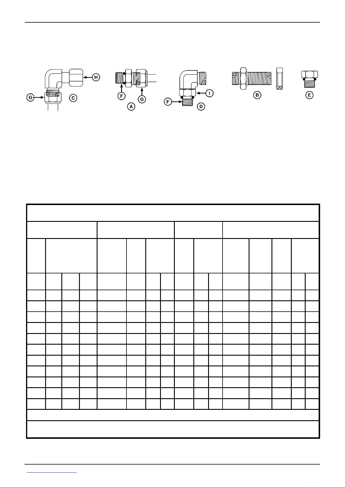
Section 10 - GENERAL INFORMATION Group 10: General Information
SAE Face Seal and O-Ring Stud End Fitting Torque
Chart—High Pressure Applications
LEGEND:
A Stud Straight and Tube Nut
B Bulkhead Union and Bulkhead Lock Nut
C 90° Swivel Elbow and Tube Nut
D 90° Adjustable Stud Elbow
E Port Plug
F Stud End
G Tube Nut
H Swivel Nut
I Lock Nut
SAE Face Seal and O-Ring Stud End Fitting Torque Chart—High Pressure - Above 27.6 MPA (4,000 PSI), Working
Pressure-41.3 MPA (6,000 PSI)
Nominal Tube OD
Hose ID
Metric
TubeODInch Tube OD
mm
5 -3 0.188 4.78 — — — — — — — 3/8-24 5/8 9/16 18 13
6 -4 0.250 6.35 9/16-18 11/16 24 18 13/16 32 24 7/16-20 5/8 5/8 24 18
8 -5 0.312 7.92 — — — — — — — 1/2-20 3/4 11/16 30 22
10 -6 0.375 9.53 11/16-16 13/16 37 27 1 42 31 9/16-18 3/4 3/4 37 27
12 -8 0.500 12.70 13/16-16 15/16 63 46 1-1/8 93 69 3/4-16 7/8 15/16 75 55
16 -10 0.625 15.88 1-14 1-1/8 103 76 1-5/16 118 87 7/8-14 1-1/16 1-1/16 103 76
20 -12 0.750 19.05 1-3/16-12 1-3/8 152 112 1-1/2 175 129 1-1/16-12 1-1/4 1-3/8 177 131
22 -14 0.875 22.23 1-3/16-12 — 152 112 — 175 129 1-3/16-12 1-3/8 1-1/2 231 170
Dash
in. mm in. in. N˙m lb-ft N˙m lb-ft in. in. in. N·m lb-ft
Size
O-Ring Face Seal/
Tube Swivel Nut
Swivel
Thread
Size
Nut
Hex
Size
Tube
Nut/Swivel
Nut
Torque
Bulkhead Jam Nut
A
Torque
Jam
Nut
Hex
Size
Jam Nut
Torque
O-Ring Straight, Adjustable, and External
Port Plug Stud Ends
Thread
Size
Straight
Hex
B
Size
A
Adj
Lock
Nut
Hex
Size
Steel
or
Gray Iron
Torque
25 -16 1.000 25.40 1-7/16-12 1-5/8 214 158 1-3/4 247 182 1-5/16-12 1-1/2 1-5/8 270 199
32 -20 1.25 31.75 1-11/16-12 1-7/8 286 211 2 328 242 1-5/8-12 1-3/4 1-7/8 286 211
38 -24 1.50 38.10 2-12 2-1/4 326 240 2-3/8 374 276 1-7/8-12 2-1/8 2-1/8 326 240
A
Tolerance is +15%, minus 20% of mean tightening torque unless otherwise specified.
B
The straight hex wrench sizes listed apply to connectors only and may not be the same as the corresponding plug of the same
thread size.
<- Go to Section TOC
Section 10 page 51
TM110119-REPAIR TECHNICAL MANUAL
Page 60

Section 10 - GENERAL INFORMATION Group 10: General Information
Four Bolt Flange Fittings Assembly and
Installation—All Pressure Applications
[1] - Inspect the sealing surfaces for nicks or scratches, roughness or out-of-flat condition.
Scratches cause leaks. Roughness causes seal wear. Out-of-flat causes seal extrusion. If
these defects cannot be polished out, replace the component.
[2] - Install the correct O-ring (and back-up washer if required) into the groove using
petroleum jelly to hold it in place.
[3] - For split flange; loosely assemble split flange halves, being sure that the split is
centrally located and perpendicular to the port. Hand tighten cap screws to hold parts in
place. Do not pinch O-ring.
[4] - For single piece flange; put hydraulic line in the center of the flange and install four cap
screws. With the flange centrally located on the port, hand tighten cap screws to hold it in
place. Do not pinch O-ring.
[5] - For both single piece flange and split flange, be sure the components are properly
positioned and cap screws are hand tight. Tighten one cap screw, then tighten the diagonally
opposite cap screw. Tighten the two remaining cap screws. Tighten all cap screws within the
specified limits shown in the chart.
DO NOT use air wrenches. DO NOT tighten one cap screw fully before tightening the others.
DO NOT overtighten.
<- Go to Section TOC
Section 10 page 52
TM110119-REPAIR TECHNICAL MANUAL
Page 61

Section 10 - GENERAL INFORMATION Group 10: General Information
SAE Four Bolt Flange Cap Screw Torque
Values—Standard Pressure Applications
SAE Four Bolt Flange Cap Screw Torque Values—27,600 KPA (4,000 PSI) Pressure Applications
Torque
Newton Meters Foot Pounds
Nominal Flange Size
1/2 5/16-18 UNC 20 31 15 23
3/4 3/8-16 UNC 28 54 21 40
1 3/8-16 UNC 37 54 27 40
1-1/4 7/16-14 UNC 47 85 35 63
1-1/2 1/2-13 UNC 62 131 46 97
2 1/2-13 UNC 73 131 54 97
2-1/2 1/2-13 UNC 107 131 79 97
3 5/8-11 UNC 187 264 138 195
3-1/2 5/8-11 UNC 158 264 117 195
4 5/8-11 UNC 158 264 117 195
5 5/8-11 UNC 158 264 117 195
Screw Size
[ JDM A17D, SAE Grade 5 or better cap screws with plated hardware. ]
[ 1.5.1.2 Lock washers are permissible but not recommended. ]
Min Max Min Max
<- Go to Section TOC
Section 10 page 53
TM110119-REPAIR TECHNICAL MANUAL
Page 62
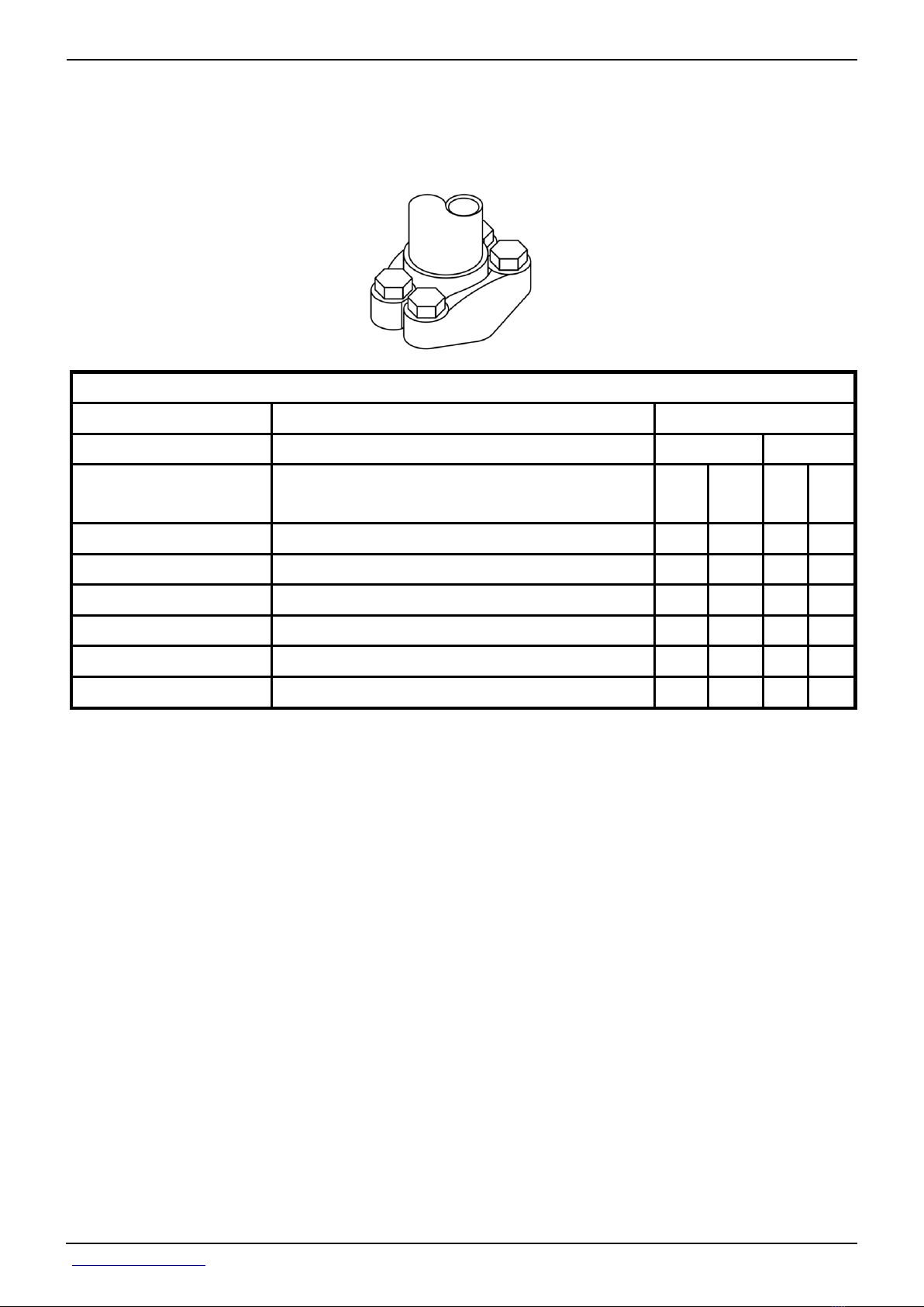
Section 10 - GENERAL INFORMATION Group 10: General Information
SAE Four Bolt Flange Cap Screw Torque
Values—High Pressure Applications
SAE Four Bolt Flange Cap Screw Torque Values—41,400 KPA (6,000 PSI) Pressure Applications
Torque
Newton Meters Foot Pounds
Nominal Flange Size
1/2 5/16-18 UNC 20 31 15 23
3/4 3/8-16 UNC 34 54 25 40
1 7/16-14 UNC 57 85 42 63
1-1/4 1/2-13 UNC 85 131 63 63
1-1/2 5/8-11 UNC 159 264 117 195
2 3/4-10 UNC 271 468 200 345
Screw Size
[ JDM A17D, SAE Grade 5 or better cap screws with plated hardware. ]
[ 1.5.1.2 Lock washers are permissible but not recommended. ]
Min Max Min Max
<- Go to Section TOC
Section 10 page 54
TM110119-REPAIR TECHNICAL MANUAL
Page 63
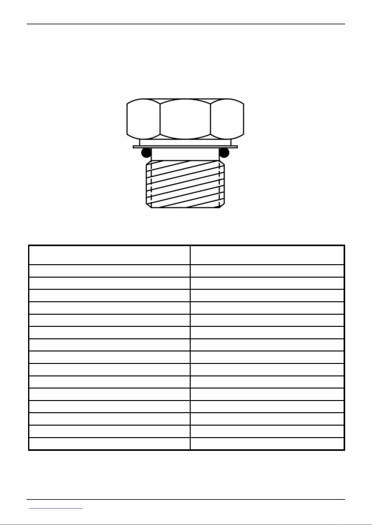
Section 10 - GENERAL INFORMATION Group 10: General Information
External Hexagon Port Plug Torque Chart
Port or Stud End Thread Size
[ Port to JDS-G173.1; stud end to JDS-G173.3. ]
M8 x 1 10 N·m (89 lb-in)
M10 x 1 17 N·m (150 lb-in)
M12 x 1.5 28 N·m (20.6 lb-ft)
M14 x 1.5 39 N·m (28.7 lb-ft)
M16 x 1.5 48 N·m (35.4 lb-ft)
M18 x 1.5 60 N·m (44.2 lb-ft)
M20 x 1.5 60 N·m (44.2 lb-ft)
M22 x 1.5 85 N·m (62.7 lb-ft)
M27 x 2 135 N·m (99.6 lb-ft)
M30 x 2 165 N·m (121.7 lb-ft)
M33 x 2 235 N·m (173.3 lb-ft)
M38 x 2 245 N·m (180.7 lb-ft)
M42 x 2 260 N·m (191.8 lb-ft)
M48 x 2 290 N·m (213.9 lb-ft)
Torque
+15%/-20%
M60 x 2 330 N·m (243.4 lb-ft)
Prevent Hydraulic System Contamination
<- Go to Section TOC
Section 10 page 55
TM110119-REPAIR TECHNICAL MANUAL
Page 64

Section 10 - GENERAL INFORMATION Group 10: General Information
IMPORTANT:
Cleanliness is very important when working on the hydraulic system.
Prevent contamination by assembling the cylinders, hoses, couplers, and
valves in a clean area of the shop.
Leave protective caps on the fluid openings until ready to make the
connection. When charging the system, use a tractor or other source that
contains clean oil, free of abrasive materials. Keep couplers clean. Abrasive
particles, like sand or metal fragments, can damage seals, barrels and
pistons, causing internal leakage.
<- Go to Section TOC
Section 10 page 56
TM110119-REPAIR TECHNICAL MANUAL
Page 65

Section 10 - GENERAL INFORMATION Group 10: General Information
Check Oil Lines and Fittings
CAUTION:
Escaping fluid under pressure can penetrate the skin causing serious
injury. Avoid the hazard by relieving pressure before disconnecting
hydraulic or other lines. Tighten all connections before applying pressure.
Search for leaks with a piece of cardboard. Protect hands and body from
high pressure fluids.
If an accident occurs, see a doctor immediately. Any fluid injected into the
skin must be surgically removed within a few hours or gangrene may
result. Doctors unfamiliar with this type of injury may call Deere &
Company Medical Department in Moline, Illinois or other knowledgeable
medical source.
Check all oil lines, hoses and fittings regularly for leaks or defects. Make sure all clamps are
in position and tight. Make sure hoses are not twisted or touching machine parts which are
moving. Replace damaged parts.
IMPORTANT:
Tighten fittings as specified in torque chart.
<- Go to Section TOC
Section 10 page 57
TM110119-REPAIR TECHNICAL MANUAL
Page 66

Section 10 - GENERAL INFORMATION Group 10: General Information
If necessary, use two wrenches to prevent hoses from twisting, bending or breaking tubing
and fittings.
<- Go to Section TOC
Section 10 page 58
TM110119-REPAIR TECHNICAL MANUAL
Page 67

Section 10 - GENERAL INFORMATION Group 10: General Information
Basic Electrical Component Handling / Precautions
For Vehicles Equipped With Computer Controlled
Systems
Electrical Precautions To Take:
Never disconnect the batteries while the key switch is running. Why: This can cause electrical
voltage spikes that can damage electronic components.
Do not connect jumper cables while the key switch is on. Why: This can cause electrical
voltage spikes that can damage electronic components.
Disconnect batteries prior to recharging (if possible). Why: Electrical loads in the combine can
slow the recharging process. Battery chargers can cause electrical voltage spikes that can
damage electronic components.
Never jump start the machine with a voltage higher than the machine is designed to operate
on. Why: This can damage electronic components.
Do not connect or disconnect electrical connectors while the key switch is on or the combine
is running. Why: This can cause computer system errors from interrupting a computer
program while it is running and electrical voltage spikes that are produced can damage
electronic components.
Do not apply power or ground to any component as a test unless specifically instructed to do
so. Why: Connecting the wrong voltage to the wrong point of an electronic system can cause
electronic component failures.
When welding on the machine, make sure to connect ground lead to the parts being welded.
For maximum protection, disconnect all electronic controller connectors before welding. Why:
High currents associated with welding can damage wiring harnesses that are involved in the
ground path. Welding can also cause electrical voltage spikes that can damage electronic
components.
Identify Zinc-Flake Coated Fasteners
<- Go to Section TOC
Section 10 page 59
TM110119-REPAIR TECHNICAL MANUAL
Page 68

Section 10 - GENERAL INFORMATION Group 10: General Information
LEGEND:
A Standard Cap Screws
B Zinc-plated Cap Screw
C Zinc-Flake Cap Screw (16 mm and larger)
Standard cap screws (A) are a reflective silver color.
Zinc plated cap screws (B) are a reflective gold color.
Zinc-Flake Coated cap screws (C) are a dull silver color.
→NOTE:
Zinc-Flake Coated fasteners are tightened to lubricated specifications,
unless otherwise noted. (See Torque Value Charts in this group.)
<- Go to Section TOC
Section 10 page 60
TM110119-REPAIR TECHNICAL MANUAL
Page 69

Section 10 - GENERAL INFORMATION Group 10: General Information
Use Torque Wrench Adapter
Tw = Torque setting on the torque wrench
Ta = Torque actually being applied to the nut or cap screw
L = Length from the point of force (center of the wrench handle) to the center of head of torque wrench
A = Application distance from center of torque wrench head to the center of adapter
<- Go to Section TOC
Section 10 page 61
TM110119-REPAIR TECHNICAL MANUAL
Page 70

Section 10 - GENERAL INFORMATION Group 10: General Information
Servicing and Connecting Snap to Connect STC™
Fittings
LEGEND:
A JDG1885
B Release Ring
C Retaining Ring
D Backup Ring
<- Go to Section TOC
Section 10 page 62
TM110119-REPAIR TECHNICAL MANUAL
Page 71

Section 10 - GENERAL INFORMATION Group 10: General Information
E O-ring
CAUTION:
Do NOT disconnect STC™ fitting when under pressure. Failure to relieve
pressure before disconnecting fitting may result in personal injury,
damage to equipment or both.
IMPORTANT:
Do not use tool to pry fitting apart, it is used only as a spacer to move
release ring (B) inward to release retaining ring (C).
→NOTE:
Snap to Connect fittings are used on steel lines, hose connections and
come in various sizes. JDG1885 STC Tools (A) are designed as a spacer to
move release ring (B) inward which releases retaining ring (C). JDG1885
STC™ tools can be purchased through SERVICEGARD.
[1] - For disassembly, perform the following: Insert correct JDG1885 STC™ tool (A)
between releasing ring (B) and fitting.
[2] - Remove hose or line pulling parallel from connector.
→NOTE:
If retaining ring, backup ring (D) or O-ring (E) are damaged, replace all
three parts.
Before connecting Snap to Connect fitting:
[1] - Check mating surfaces for nicks, scratches, or flat spots.
[2] - Check O-ring, backup ring, and retaining ring for wear or damage. Replace as needed.
[3] - Ensure that both female and male ends are clean and free of contaminates.
[4] - Push fitting connections parallel together until a definite snap and solid stop is felt.
[5] - Pull parallel back on hose to ensure that fitting connections are locked together.
<- Go to Section TOC
Section 10 page 63
TM110119-REPAIR TECHNICAL MANUAL
Page 72

Section 10 - GENERAL INFORMATION Group 10: General Information
Glossary of Terms
<- Go to Section TOC
Section 10 page 64
TM110119-REPAIR TECHNICAL MANUAL
Page 73

ENGINE
ITEM ABBREVIATION DESCRIPTION
Accessory ACC Secondary electrical system
AutoQuad-Plus Transmission AQ+ Abbreviation
Automatic Powershift APS Transmission feature
Active Seat ™ Control Unit ASU Computerized system used to control the ActiveSeat™
Air Conditioning A/C System used conditioning the air in the cab
Air Quality System AQS System used to control conditioned air in the cab
Alternating Current AC Electrical current that reverses its direction at regularly recurring intervals
Armrest Control Unit ACU Armrest control used to control tractor functions
Auto-Temperature Control ATC Automatically controlled air quality system
Battery Bat A device used to furnish electrical current
Brakes BR Abbreviation
Brake Control Unit BRC Computerized system for brake control
Brake Load Sense BRL Reference—Brake load sense
Cab Control Unit CAB Computerized system for controlling cab electronic functions
Controller Area Network CAN A communication system linking on-board electronics
Chassis Control Unit CCU Computerized system for tractor monitoring
Circuit CCT A complete path of an electrical current
Circulation Motor Symbols for circulation motor speeds
Cab Load Center CLC Computerized system for controlling cab electrical functions
Clean Oil Reservoir COR Reservoir used to contain oil for the tractor hydraulic system
ClimaTrak ™ Automatically controlled air quality system
Clockwise CW Direction in which the hands of a clock rotate
Cold Cranking Amperes CCA Refers to a battery′s capability to perform during cold-weather operation
Component Technical Manual CTM Technical manual developed for the servicing of major components
Counterclockwise CCW Direction opposite the rotation of the hands of a clock
Control Flow (Steering Pressure) CF Reference—Steering pressure control flow
Control Flow DR CFD Reference—Control flow diagnostic receptacle
Corner Post Display CPD Display for system control units
Diagnostic Receptacle DR A connection where hydraulic pressure can be measured
Digital Multimeter DMM An electrical multifunctional measuring device
Direct Current DC Electrical current flowing in one direction only
Displacement Control Valve DCV Controls hydraulic pump stroke
Economy Mode ECO Abbreviation
Electronic Displacement Control EDC Senses and communicates to the displacement control valve demand for hydraulic pump stroke
Electrohydraulic EH Refers to a hydraulic valve function that is controlled electrically
Electrohydraulic Depth Control EHDC Abbreviation
Electro-hydraulic Option Control Unit EHO Computerized system used to control the independent link suspension axle
Electrohydraulic Selective Control Valve EH SCV Selective control valve operated with electrical solenoids
Electronic Components Relay ELX Refers to the relay powering most of the electronic components
Engine Control Unit ECU Computerized system used to govern engine speed
Electronically Programmable Read-Only Memory EPROM Abbreviation
Evacuation Diagnostic Receptacle EVAC Diagnostic receptacle port used for pre-lubrication of the pump drive gears
Excess Flow (SCV/Hitch Flow) EF Reference—SCV/Hitch flow
Excess Flow Load Sense (SCV/Hitch Flow) EFL Reference—SCV/Hitch load sense
Forward-Neutral-Reverse FNR Abbreviation
Forward FWD Refers to direction of movement
Gallons Per Minute gpm Amount of fluid over a period of one minute
GreenStar™ System GSS Part of John Deere Precision Farming Systems
Ground-Driven Pump GDP Pump used to operate steering and brakes during emergency conditions
Global Positioning System GPS Abbreviation
Heating-Ventilating and Air Conditioning HVAC Abbreviation
High-Intensity Discharge Light HID Abbreviation
High Pressure - Common Rail HPCR Fuel injected engine that utilizes high pressure fuel injection and a common pressure rail
Hitch Control Unit HCU Computerized system used to control hitch functions
Hitch Slip Command HSC System to compensate for traction changes
Housing Hsg Abbreviation
Ignition IGN Control for starting and stopping the tractor
Implement Management System IMS Control for operating equipment
Independent Link Suspension ILS Front axle with an active suspension system that is electrohydraulic controlled
Inside Diameter ID Abbreviation
Instrument Control Unit ICU Computerized system controlling tractor warning functions
International Standards Organization ISO Standards organization
Infinitely Variable Transmission IVT A hydro-mechanical transmission with infinitely variable speeds
Joint Industry Council Organization JIC Standards organization
Lateral Hitch Position LHP Refers to hitch positioning for a row guidance hitch application
Left-Hand LH or L-H Abbreviation
Liquid Crystal Display LCD A technology used for displaying information
Manifold Air Pressure MAP Abbreviation
Mechanical Front Wheel Drive MFWD A mechanically powered front axle
Negative Neg (—) Refers to a part of an electrical circuit
Number No. Abbreviation
O-Ring Face Seal
Outside Diameter OD Abbreviation
Performance Monitor
Positive Pos (+) Refers to a part of an electrical circuit
Potentiometer POT A device used to vary electrical voltage
PowerQuad-Plus Transmission PQ+ Abbreviation
Powershift Transmission PST Abbreviation
IVT Transmission Control Unit PTI Computerized system used to control IVT transmission shift functions
Power Take-Off PTO Abbreviation
Powershift Transmission Control Unit PTP Computerized system used to control powershift transmission shift functions
Pressure Control Valve PCV Valve used to control pressure within a system
Pressure Regulating Valve PRV A device used to regulate pressure in a system
Product Identification Number PIN Serial number relating to tractor identification
Pulse-Width-Modulation PWM Method of controlling electrical signals
Pump DR PD Reference—Pump diagnostic receptacle
Pump Load Sense PLD Reference—Pump load sense
Reverse Rev Refers to direction of movement
Revolutions Per Minute rpm Abbreviation
Right-Hand
Rockshaft RS Abbreviation
Selective Control Option SCo Control unit for selective control valves 4 and 5
Selective Control Unit SCU Computerized system used to control selective control valve functions for selective control valves 1, 2, and 3
Selective Control Valve SCV Device used to control remote hydraulic functions
Steering Control Unit SSU Computerized system controlling tractor steering
Setup Panel SUP Operator control panel used to set selective control valve function
Slow Moving Vehicle SMV Warning sign on the rear of the tractor
Society of Automotive Engineers SAE Engineering Standards Organization
Specification SPEC Abbreviation
Suspended Front Axle SFA Front axle with an active suspension system that is electronically controlled
Tracks Tractor Steering System Control Unit SST Computerized system controlling tractor steering for tracks tractors
Wheel Tractor Steering System Control Unit SSU Computerized system controlling tractor steering for wheel tractors equipped with AutoTrac™
Steering Load Sense STL Reference—Steering load sense
Switch SW Abbreviation
Tachometer Tach Abbreviation
Terrain Compensation Module TCM Electronic module that corrects for vehicle dynamics such as roll on side-slopes and rough terrain
Tail Light TL Abbreviation
Tractor Control Unit - Vehicle TEC Electronic system for communicating between vehicle and implement
Tractor Control Unit - Implement TEI Electronic system for communicating between implement and vehicle
Temperature Temp Abbreviation
Transmission Trans Abbreviation
TouchSet Depth Control TSDC Abbreviation-Same as EHDC
Transient Voltage Protection TVP An electrical device used to protect a circuit from voltage surge
Voltage (Volts) V Abbreviation
Voltage Detector V Det Abbreviation
Vehicle Load Center VLC Computerized system for controlling vehicle electrical functions
Warning Lamp WL Abbreviation
Without W/O Abbreviation
Wide-Open Throttle WOT Full throttle
Two Wheel Drive 2WD Vehicle where only one pair of wheels is powered
O Medium Speed
+ Fastest Speed
ORFS
ORS
Perf Mon
(PrF)
RH or
R-H
A type of seal used in making hydraulic connections
Abbreviation
Abbreviation
(g) by Belgreen
<- Go to Section TOC
Section 10 page 65
TM110119-REPAIR TECHNICAL MANUAL
Page 74

ENGINE
(g) by Belgreen
<- Go to Section TOC
Section 10 page 66
TM110119-REPAIR TECHNICAL MANUAL
Page 75

TM110119-REPAIR TECHNICAL MANUAL
Section 20 - ENGINE
Table of contents
Group 00 - Component Removal and Installation 1 ................................................................
List of References 1 ..................................................................................................................
Essential, Recommended, and Fabricated Tools 1 ....................................................................
Other Material 1 ........................................................................................................................
Specifications 2 .........................................................................................................................
Remove and Install 6.8L Engine 3 .............................................................................................
Remove and Install 9.0L Engine 16 ...........................................................................................
Group 05 - Engine Repair 27 .......................................................................................................
List of References 27 ................................................................................................................
Essential, Recommended, and Fabricated Tools 27 ..................................................................
Specifications 27 .......................................................................................................................
Repair Engine—Use CTM 28 ......................................................................................................
Remove and Install 6.8L Engine Rocker Arm Cover 29 .............................................................
Remove and Install 9.0L Engine Rocker Arm Cover 39 .............................................................
Replace Flywheel Dampener 47 ................................................................................................
(g) by Belgreen
<- Go to Global Table of contents TM110119-REPAIR TECHNICAL MANUAL
Page 76

Section 20 - ENGINE Group 00: Component Removal and Installation
Group 00 - Component Removal and Installation
List of References
Below is a list of all items within this group.
Essential, Recommended, and Fabricated Tools
Other Material
Specifications
Remove and Install 6.8L Engine
Remove and Install 9.0L Engine
Essential, Recommended, and Fabricated Tools
→NOTE:
Order tools according to information given in the U.S. SERVICEGARD™
Catalog or from the European Microfiche Tool Catalog (MTC).
Below are tools listed in this group.
JDG19 Lifting Eyes
JDG820 Flywheel Rotation Tool
JDG11252 Front Lifting Bracket
JDG11258 Rear Lifting Bracket
JDG11260 Lifting Bracket
JT07336 Lift Sling
Other Material
Number Name Use
• PM38657 (us)
• TY9484 (canadian)
• 17430 Loctite ™ (loctite)
<- Go to Section TOC
High Flex Form-In-Place Gasket Used to seal surfaces.
Section 20 page 1
TM110119-REPAIR TECHNICAL MANUAL
Page 77

Section 20 - ENGINE Group 00: Component Removal and Installation
Specifications
Item Measurement Specification
Engine Lifting Brackets Cap Screws Torque 170 N·m
(125 lb.-ft.)
6.8L Torque Turn Cap Screws (1—10) Torque Turn 30 N·m + 90° Turn
(265 lb.-in.+ 90° Turn)
6.8L Torque Turn Cap Screws (11—24) Torque Turn 30 N·m + 90° Turn
(265 lb.-in.+ 90° Turn)
6.8L Torque Turn Cap Screws (25 and 26) Torque Turn 50 N·m + 120° Turn
(37 lb.-ft. + 120° Turn)
6.8L Cap Screws Torque (27—36) Torque 35 N·m
26 lb.-ft.
Drive Shaft Yoke-to-Engine Cap Screws Torque 70 N·m
(52 lb.-ft.)
9.0L Torque Turn Cap Screws (1—18) Torque Turn 140 N·m + 90° Turn
(103 lb.-ft...+ 90° Turn)
9.0L Torque Turn Cap Screws (19—20) Torque Turn 200 N·m + 90° Turn
(148 lb.-ft.+ 90° Turn)
9.0L Torque Turn Cap Screws (21 —24) Torque Turn 45 N·m + 120° Turn
(33 lb.-ft. + 120° Turn)
<- Go to Section TOC
Section 20 page 2
TM110119-REPAIR TECHNICAL MANUAL
Page 78

Section 20 - ENGINE Group 00: Component Removal and Installation
Remove and Install 6.8L Engine
[1] - Remove hood and side shields.
[2] - Disconnect battery ground (—) cable at batteries.
[3] - Discharge air conditioning system. (See Discharge Air Conditioning System in Section 90
Group 10.)
[4] - Drain engine coolant from radiator and engine block.
[5] - Disconnect starter wiring harness.
<- Go to Section TOC
Section 20 page 3
TM110119-REPAIR TECHNICAL MANUAL
Page 79

Section 20 - ENGINE Group 00: Component Removal and Installation
[6] -
LEGEND:
A Upper Radiator Hose
B Deaeration Tank
C Left-Hand Air-to-Air Cooler Pipe
D Air Cleaner Pipe
E Bracket
F Rear Heat Shield
Disconnect upper radiator hose (A).
[7] - Remove deaeration tank (B).
[8] - Remove clamps and remove left-hand air-to-air cooler pipe (C).
[9] - Disconnect air cleaner pipe (D).
[10] - Remove bracket (E).
[11] - Remove heat shield (F).
<- Go to Section TOC
Section 20 page 4
TM110119-REPAIR TECHNICAL MANUAL
Page 80

Section 20 - ENGINE Group 00: Component Removal and Installation
[12] -
LEGEND:
A Fuel Cooler Lines
B Lower Radiator Hose
C Right-Hand Air-to-Air Cooler Pipe
D Harness Cover
E Heat Shields
F Bracket
G Exhaust Pipes
H Cap Screw (2 used)
Disconnect fuel cooler lines (A) to line bundle.
[13] - Remove lower radiator hose (B).
[14] - Remove right-hand air-to-air cooler pipe (C).
[15] - Remove harness cover (D).
[16] - Remove heat shield (E).
<- Go to Section TOC
Section 20 page 5
TM110119-REPAIR TECHNICAL MANUAL
Page 81

Section 20 - ENGINE Group 00: Component Removal and Installation
[17] - Remove bracket (F).
[18] - Remove exhaust pipes (G). (See Service Exhaust System in Section 30, Group 30.)
[19] - Remove cap screws (H) from line bundle support.
[20] -
LEGEND:
A Cap Screw (6 used)
B Auxiliary Drive Shaft
Remove cap screws (A).
[21] - Pry auxiliary drive shaft (A) forward away from engine.
<- Go to Section TOC
Section 20 page 6
TM110119-REPAIR TECHNICAL MANUAL
Page 82

Section 20 - ENGINE Group 00: Component Removal and Installation
[22] -
LEGEND:
A Line Bundle Mounting Cap Screws (2 used)
B Cap Screws (2 used)
C Cap Screws (4 used)
D Hood Support
Remove line bundle mounting cap screws (A).
[23] - Remove line bundle mounting cap screws (B).
[24] - Remove any line and harness clamps from hood support (D).
[25] - Remove mounting cap screws (C) at frame and remove hood support (D) out left-hand
side.
[26] -
<- Go to Section TOC
Section 20 page 7
TM110119-REPAIR TECHNICAL MANUAL
Page 83

Section 20 - ENGINE Group 00: Component Removal and Installation
<- Go to Section TOC
Section 20 page 8
TM110119-REPAIR TECHNICAL MANUAL
Page 84
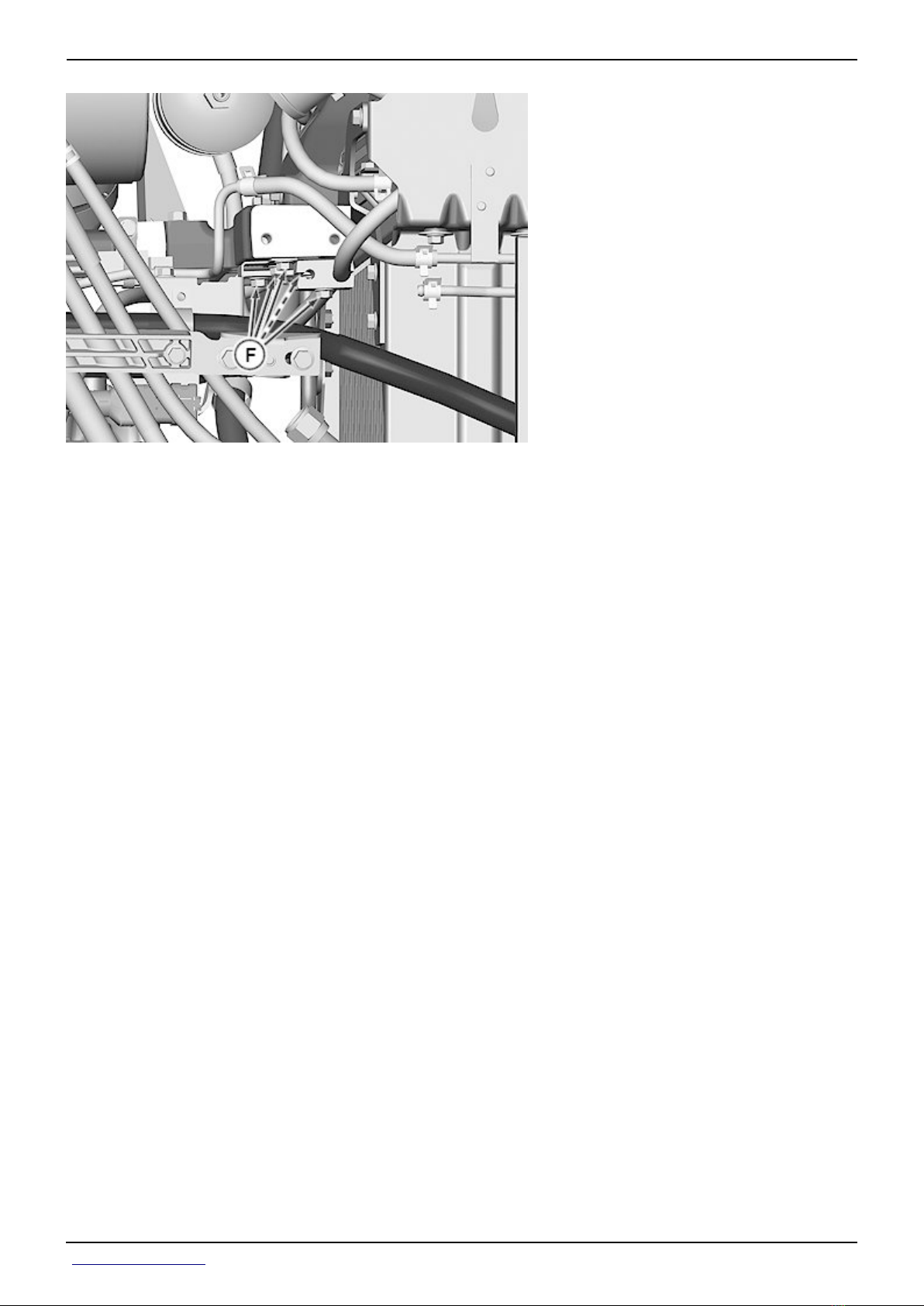
Section 20 - ENGINE Group 00: Component Removal and Installation
LEGEND:
A Clamps (2 used)
B Receiver Dryer
C Cap Screws (3 used)
D Exhaust Filter Sensor Harness Connector
E Line Bundle
F Cap Screws (5 used)
Remove clamps (A).
[27] - Disconnect receiver dryer (B).
[28] - Remove cap screws (C and F).
[29] - Disconnect exhaust filter sensor harness connector (D).
[30] - Remove any line and harness clamps from hood support.
[31] - Tilt line bundle (E) to the right-hand side of tractor.
<- Go to Section TOC
Section 20 page 9
TM110119-REPAIR TECHNICAL MANUAL
Page 85

Section 20 - ENGINE Group 00: Component Removal and Installation
[32] -
LEGEND:
A Lift Straps (2 used)
B Exhaust Filter and Bracket
Install lift straps (A) as shown around exhaust filter.
[33] - Remove exhaust filter and bracket (B) with hoist.
[34] -
IMPORTANT:
Lift straps must be tightened to prevent damage to injection lines and
other engine components during engine removal.
<- Go to Section TOC
Section 20 page 10
TM110119-REPAIR TECHNICAL MANUAL
Page 86

Section 20 - ENGINE Group 00: Component Removal and Installation
LEGEND:
A JDG11260 Rear Lift Brackets
B JDG11260 Front Lift Brackets
C JT07336 Lifting Sling
Attach JDG11260 Lifting Bracket (A and B) with cap screws and tighten cap screws to the
following specifications.
Item Measurement Specification
Engine Lifting Brackets Cap Screws Torque 170 N·m
(125 lb.-ft.)
[35] - Disconnect drive shaft from engine using JDG820 Flywheel Rotation Tool to rotate
drive shaft for access to cap screws.
<- Go to Section TOC
Section 20 page 11
TM110119-REPAIR TECHNICAL MANUAL
Page 87
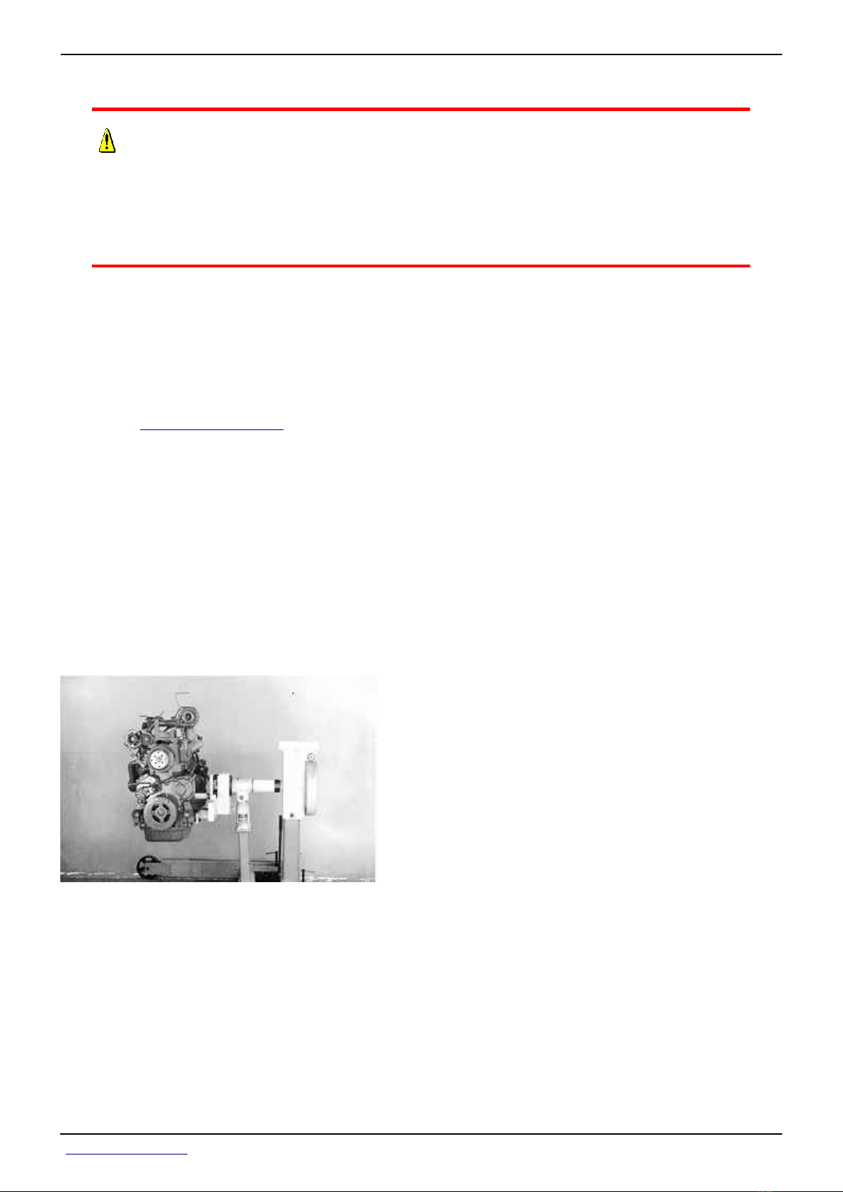
Section 20 - ENGINE Group 00: Component Removal and Installation
[36] -
CAUTION:
The only recommended method for lifting the engine is with JT07336
Engine Lifting Sling and safety approved lifting straps. Use extreme
caution when lifting and NEVER permit any part of the body to be
positioned under an engine being lifted or suspended.
IMPORTANT:
Lift engine with longitudinal loading on lifting sling and lifting brackets
only. Angular loading greatly reduces lifting capacity of sling and brackets.
Lift spacing on sling is adjustable. Position each lifting point so that engine
hangs level when lifted.
Attach the JT07336 Lift Sling (C) to JDG11260 Lift brackets (A and B) and overhead hoist or
floor crane.
[37] - Remove oil pan cap screws.
[38] -
IMPORTANT:
Move the engine control unit with wiring harness toward the engine to
prevent interference during engine removal.
Carefully remove engine, rotating the front end upward and forward as engine is being
removed.
Refer to engine CTM for procedure to install engine in repair stand.
<- Go to Section TOC
Section 20 page 12
TM110119-REPAIR TECHNICAL MANUAL
Page 88

Section 20 - ENGINE Group 00: Component Removal and Installation
[1] - Install engine noting the following instructions:
LEGEND:
A Sealant
Remove any gasket or oil residue from mating parts.
[2] - Apply sealant (A)
Number Name Use
• PM38657 (us)
• TY9484 (canadian)
High Flex Form-In-Place Gasket Used to seal surfaces.
• 17430 Loctite ™ (loctite)
at the jointed edges created by the flywheel housing, front plate, and timing gear cover.
<- Go to Section TOC
Section 20 page 13
TM110119-REPAIR TECHNICAL MANUAL
Page 89

Section 20 - ENGINE Group 00: Component Removal and Installation
[3] -
LEGEND:
A Cap Screws (1—10)
B Cap Screws (11—24)
C Cap Screws (25 and 26)
D Cap Screws (27—36)
IMPORTANT:
Tighten all cap screws using sequence and torque turn strategy.
Tighten cap screws (A) to the following specifications.
Item Measurement Specification
6.8L Torque Turn Cap Screws (1—10) Torque Turn 30 N·m + 90° Turn
(265 lb.-in.+ 90° Turn)
[4] - Tighten cap screws (B) to the following specifications.
Item Measurement Specification
6.8L Torque Turn Cap Screws (11—24) Torque Turn 30 N·m + 90° Turn
(265 lb.-in.+ 90° Turn)
[5] - Tighten cap screws (C) to the following specifications.
Item Measurement Specification
6.8L Torque Turn Cap Screws (25 and 26) Torque Turn 50 N·m + 120° Turn
(37 lb.-ft. + 120° Turn)
<- Go to Section TOC
Section 20 page 14
TM110119-REPAIR TECHNICAL MANUAL
Page 90

Section 20 - ENGINE Group 00: Component Removal and Installation
[6] - Tighten cap screws (D) to the following specifications.
Item Measurement Specification
6.8L Cap Screws Torque (27—36) Torque 35 N·m
26 lb.-ft.
[7] - Tighten drive shaft yoke cap screws to specification.
Item Measurement Specification
Drive Shaft Yoke-to-Engine Cap Screws Torque 70 N·m
(52 lb.-ft.)
<- Go to Section TOC
Section 20 page 15
TM110119-REPAIR TECHNICAL MANUAL
Page 91

Section 20 - ENGINE Group 00: Component Removal and Installation
Remove and Install 9.0L Engine
[1] - Remove hood and side shields.
[2] - Discharge air conditioning system. (See Discharge Air Conditioning System in Section 90
Group 10.)
[3] - Disconnect battery ground (—) cable at batteries.
[4] - Drain engine coolant from radiator.
[5] -
LEGEND:
A Upper Radiator Hose
B Left-Hand Air-to -Air Cooler Pipe
C Air Cleaner Pipe
D Starter Wiring
E Exhaust Pipe
F Rear Heat Shields
Disconnect upper radiator hose (A).
[6] - Remove clamps and remove left-hand air-to-air cooler pipe (B).
[7] - Disconnect air cleaner pipe (C).
[8] - Disconnect starter wiring harness (D).
[9] - Remove bracket (E).
[10] - Remove rear heat shields (F).
<- Go to Section TOC
Section 20 page 16
TM110119-REPAIR TECHNICAL MANUAL
Page 92

Section 20 - ENGINE Group 00: Component Removal and Installation
[11] -
LEGEND:
A Cap Screw (6 used)
B Auxiliary Drive Shaft
Remove cap screws (A).
[12] - Pry auxiliary drive shaft (A) forward away from engine.
[13] -
LEGEND:
A Fuel Cooler Lines
B Lower Radiator Hose
C Harness Cover
D Hood Spreader Bracket
E Exhaust Pipes
F Line Bundle Mounting Cap Screw (2 used)
Disconnect fuel cooler lines (A) to line bundle.
<- Go to Section TOC
Section 20 page 17
TM110119-REPAIR TECHNICAL MANUAL
Page 93
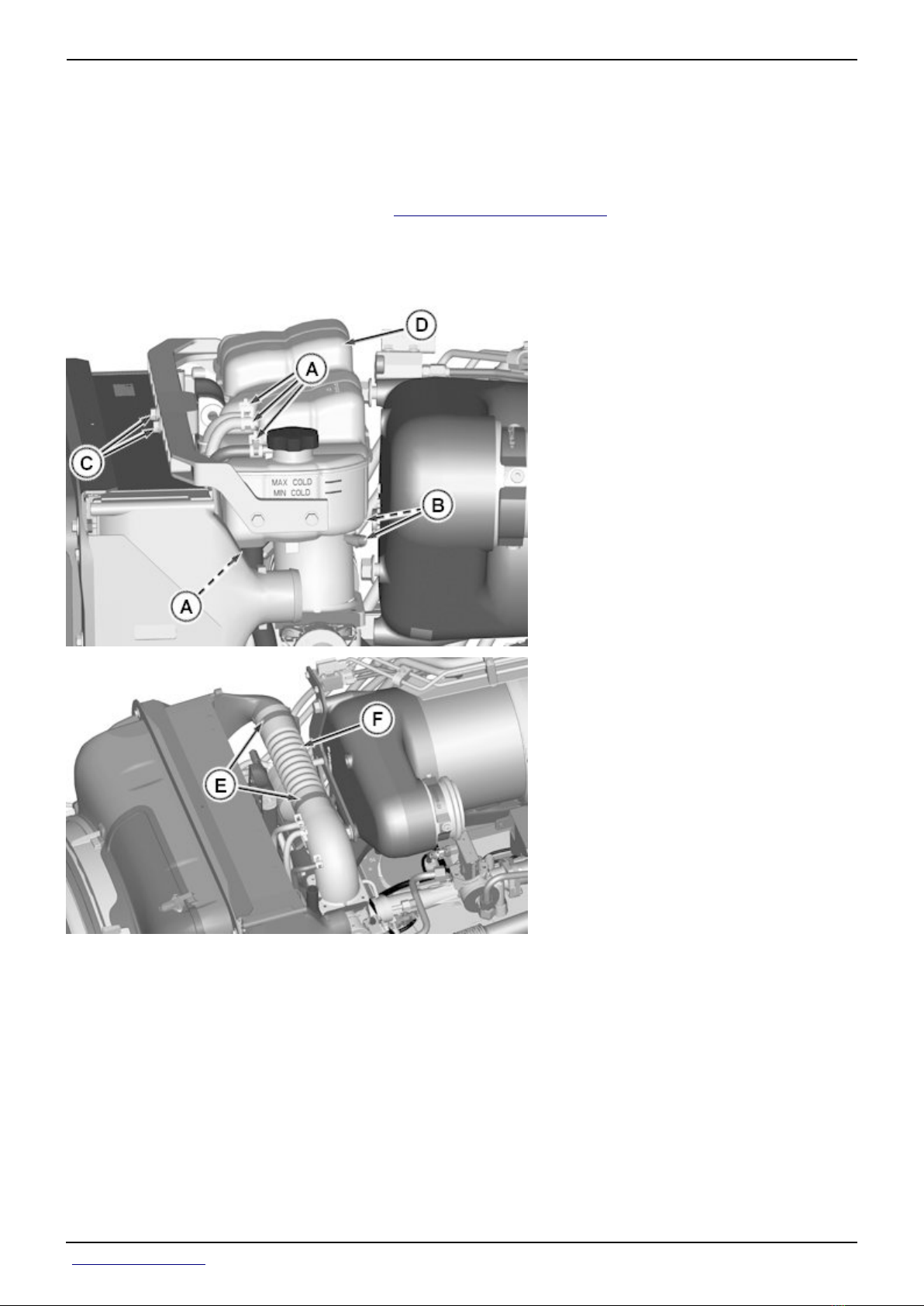
Section 20 - ENGINE Group 00: Component Removal and Installation
[14] - Remove lower radiator hose (B).
[15] - Remove harness cover (C).
[16] - Remove bracket (F).
[17] - Remove exhaust pipes (G). (See Service Exhaust System in Section 30, Group 30.)
[18] - Remove cap screws (F) from line bundle support.
[19] -
LEGEND:
A Hoses
B Sensor Connectors
C Cap Screws (2 used)
D Deaeration Tank
E Clamps (2 used)
F Charge Air Hose
Disconnect hoses (A).
[20] - Disconnect sensor connectors (B).
[21] - Remove cap screws (C) and deaeration tank (D).
<- Go to Section TOC
Section 20 page 18
TM110119-REPAIR TECHNICAL MANUAL
Page 94

Section 20 - ENGINE Group 00: Component Removal and Installation
[22] - Remove clamps (E) and charge air hose (F).
[23] -
LEGEND:
A Cap Screws (2 used)
B Heater Hoses (2 used)
C Line Bundle
D Cap Screws (4 used)
E Cap Screws (2 used)
F Hood Support
Remove line bundle mounting cap screws (A).
[24] - Disconnect heater hoses (B).
<- Go to Section TOC
Section 20 page 19
TM110119-REPAIR TECHNICAL MANUAL
Page 95
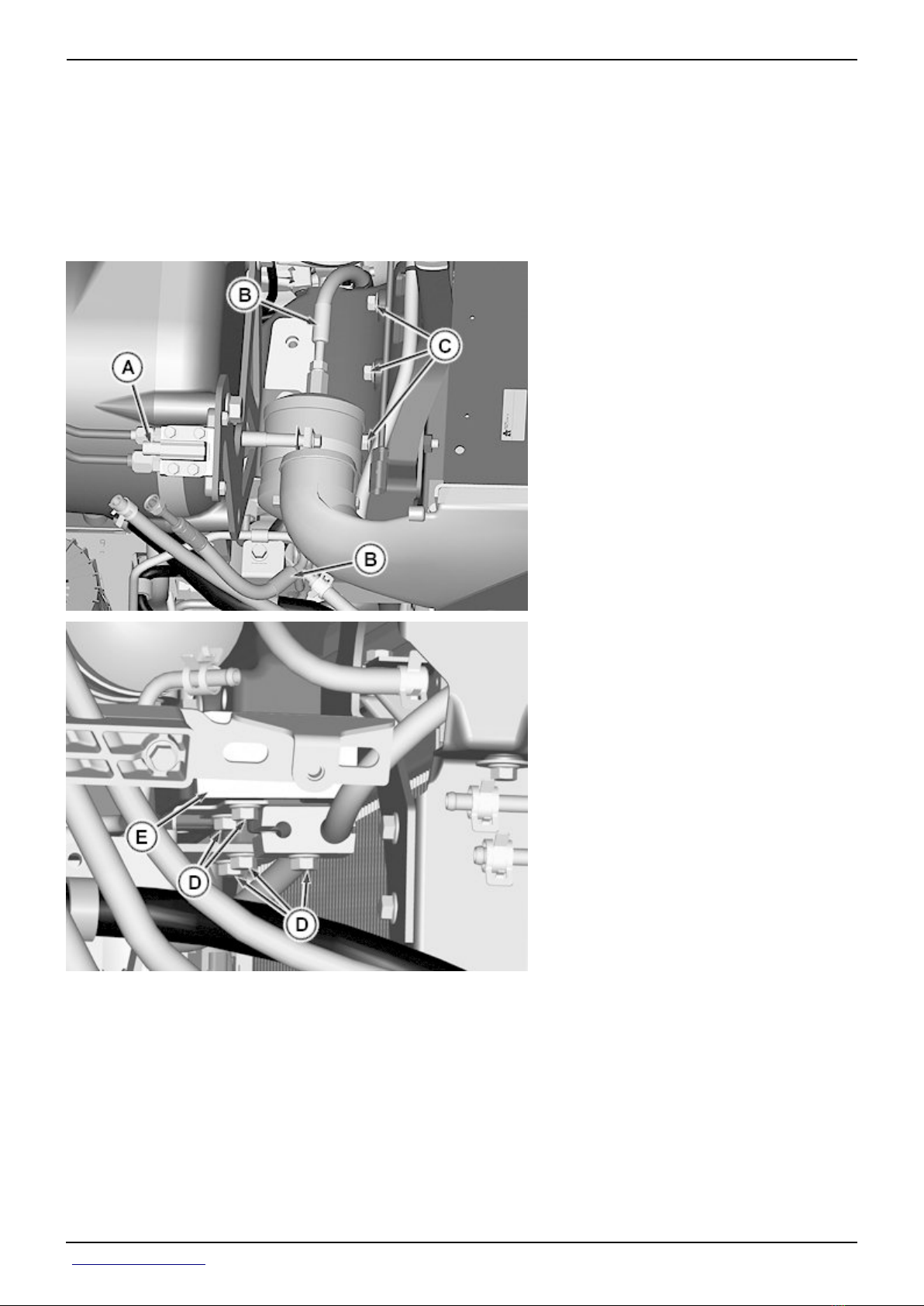
Section 20 - ENGINE Group 00: Component Removal and Installation
[25] - Tilt line bundle (C) to right-hand side of tractor.
[26] - Remove any line and harness clamps from hood support.
[27] - Remove cap screws (D) from both sides.
[28] - Remove cap screws (E) and remove hood support (F) out left-hand side.
[29] -
LEGEND:
A Exhaust Filter Sensor Harness Connector
B Receiver Dryer Lines
C Cap Screws (3 used)
D Cap Screws (5 used)
E Exhaust Filter Support Frame
Disconnect exhaust filter sensor harness connector (A).
[30] - Disconnect receiver dryer lines (B).
[31] - Remove cap screws (C).
<- Go to Section TOC
Section 20 page 20
TM110119-REPAIR TECHNICAL MANUAL
Page 96
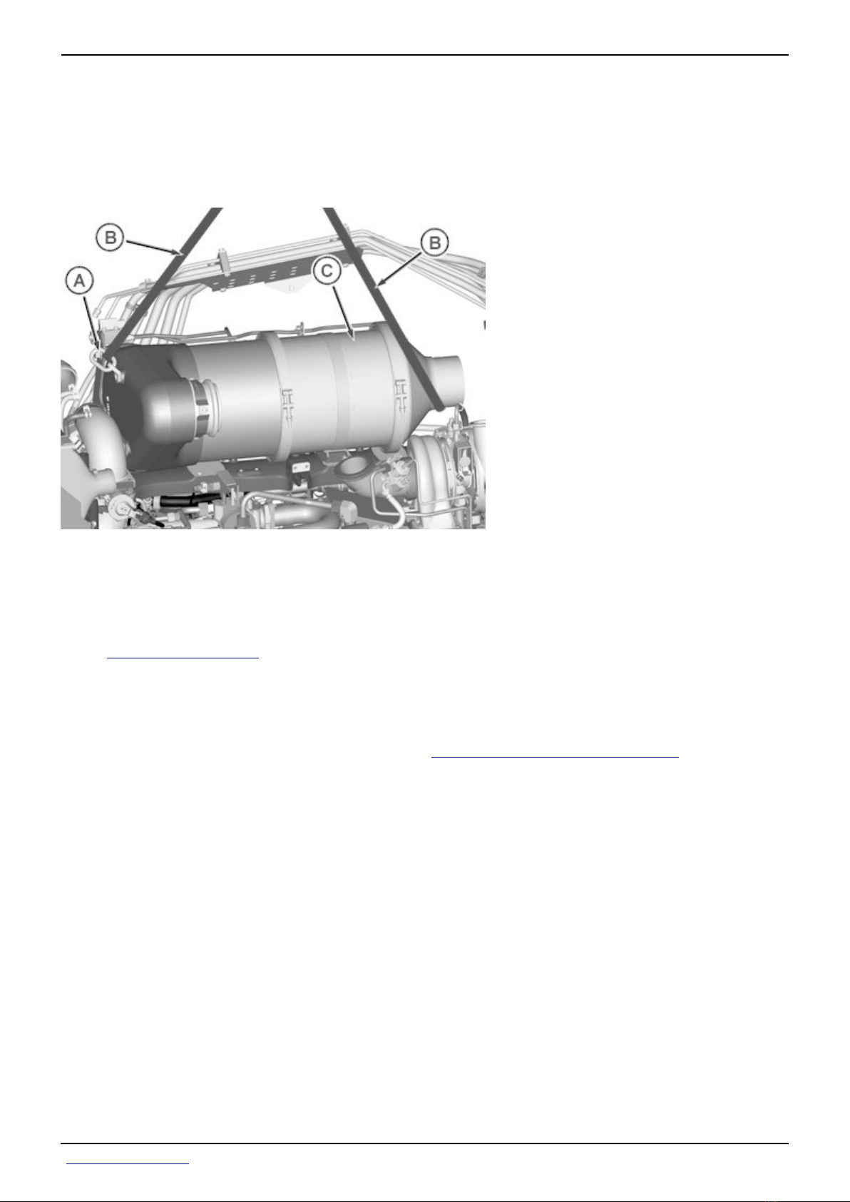
Section 20 - ENGINE Group 00: Component Removal and Installation
[32] - Remove remaining harness and hose clamps from exhaust filter support frame.
[33] - Remove cap screws (D) under exhaust filter support frame (E).
[34] - Disconnect heater return hose from steel line on exhaust filter support frame (E).
[35] -
LEGEND:
A JDG19 Lifting Eye
B Lift Straps (2 used)
C Exhaust Filter and Support Frame
Install JDG19 Lifting Eyes (A) as shown.
[36] - Install lift straps (B) as shown around exhaust filter and lift eye.
[37] - Remove exhaust filter and support frame (C) with hoist.
[38] - Disconnect drive shaft from engine using JDG820 Flywheel Rotation Tool to rotate
drive shaft for access to cap screws.
[39] -
IMPORTANT:
Lift straps must be tightened to prevent damage to injection lines and
other engine components during engine removal.
<- Go to Section TOC
Section 20 page 21
TM110119-REPAIR TECHNICAL MANUAL
Page 97
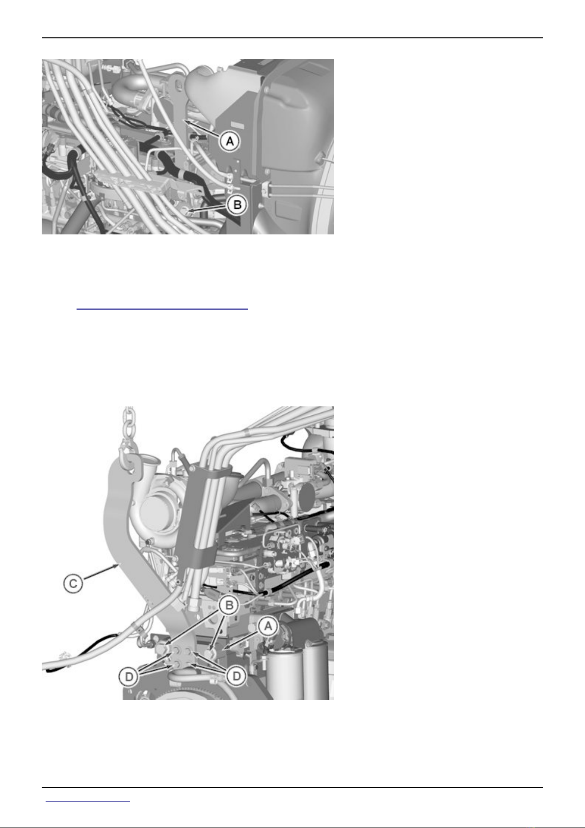
Section 20 - ENGINE Group 00: Component Removal and Installation
LEGEND:
A JDG11252 Front Lift Bracket
B Cap Screw
Attach JDG11252 Front Lifting Bracket (A) with cap screw (B) and tighten.
[40] -
IMPORTANT:
Lift bracket must be tightened to prevent damage to injection lines and
other engine components during engine removal.
LEGEND:
A Bracket of JDG11258 Rear Lift Bracket
B Cap Screw M20 X 70 mm (2 used)
C Upright Strap of JDG11258 Rear Lift Bracket
D Cap Screw (4 used)
<- Go to Section TOC
Section 20 page 22
TM110119-REPAIR TECHNICAL MANUAL
Page 98

Section 20 - ENGINE Group 00: Component Removal and Installation
Attach bracket (A) of JDG11258 Rear Lifting Bracket with cap screws (B) to rear of engine
block and tighten.
[41] - Attach upright strap (C) of JDG11258 Rear Lift Strap with special cap screw (D) to
bracket and tighten.
[42] -
CAUTION:
The only recommended method for lifting the engine is with JT07336
Engine Lifting Sling and safety approved lifting straps. Use extreme
caution when lifting and NEVER permit any part of the body to be
positioned under an engine being lifted or suspended.
IMPORTANT:
Lift engine with longitudinal loading on lifting sling and lifting brackets
only. Angular loading greatly reduces lifting capacity of sling and brackets.
Lift spacing on sling is adjustable. Position each lifting point so that engine
hangs level when lifted.
LEGEND:
A JDG11252 Front Lift Bracket
B JDG11258 Rear Lift Bracket
C JT07336 Lifting Sling
Attach JT07336 Lift Sling (C) to overhead hoist or floor crane and JDG11252 front lift bracket
(A) and JDG11258 rear lift bracket (B).
[43] - Remove oil pan cap screws.
<- Go to Section TOC
Section 20 page 23
TM110119-REPAIR TECHNICAL MANUAL
Page 99
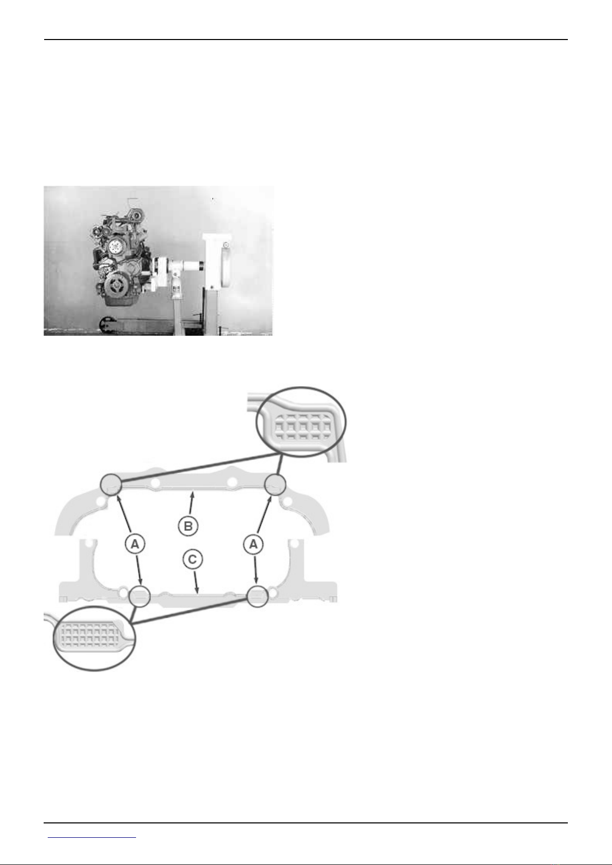
Section 20 - ENGINE Group 00: Component Removal and Installation
[44] -
IMPORTANT:
Move engine control unit with wiring harness toward the engine to prevent
interference during engine removal.
Carefully remove engine, rotating the front end upward and forward as engine is being
removed.
Refer to engine CTM for procedure to install engine in repair stand.
[1] - Install engine noting the following instructions:
LEGEND:
A High Flex Form-In-Place Gasket Location (4 used)
B Front of Pan Gasket
C Rear of Pan Gasket
Remove any gasket or oil residue from mating parts.
<- Go to Section TOC
Section 20 page 24
TM110119-REPAIR TECHNICAL MANUAL
Page 100
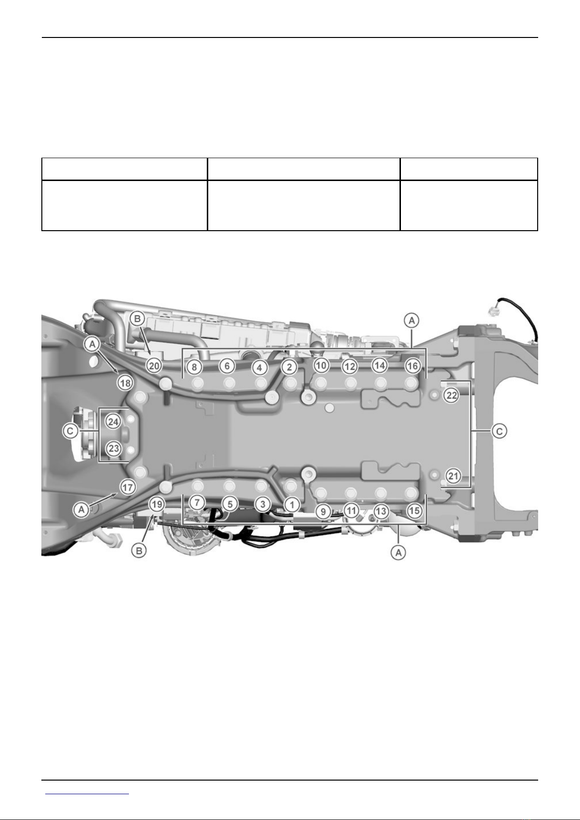
Section 20 - ENGINE Group 00: Component Removal and Installation
[2] -
IMPORTANT:
High Flex Form-In-Place Gasket is used on block side of gasket to seal area
created by the flywheel housing, front plate, and timing gear cover.
Apply
Number Name Use
• PM38657 (us)
• TY9484 (canadian)
High Flex Form-In-Place Gasket Used to seal surfaces.
• 17430 Loctite ™ (loctite)
high flex form-in-place gasket in location (A) on block side of gasket at front of pan gasket (B)
and rear of pan gasket (C).
[3] -
LEGEND:
A Cap Screws (1—18)
B Cap Screws (19 and 20)
C Cap Screws (21 —24)
IMPORTANT:
Tighten all cap screws using sequence and torque turn strategy.
Tighten cap screws (A) to the following specifications.
Item Measurement Specification
9.0L Torque Turn Cap Screws (1—18) Torque Turn 140 N·m + 90° Turn
(103 lb.-ft...+ 90° Turn)
<- Go to Section TOC
Section 20 page 25
TM110119-REPAIR TECHNICAL MANUAL
 Loading...