

Page 1

655, 755, 855, 955,
756 and 856 Compact
Utility Tractors
TECHNICAL
MANUAL
John Deere
Lawn & Grounds Care Division
TM1360 (June 1996)
Litho in U.S.A
Page 2

FOREWORD
Introduction
This manual is written for an experienced technician.
Essential tools required in performing certain service
work are identified in this manual and are
recommended for use.
LIVE WITH SAFETY: Read the safety messages in
the introduction of this manual and the cautions
presented throughout the text of the manual.
This is the safety-alert symbol. When you see
this symbol on the machine or in this manual,
P
be alert to the potential for personal injury.
Technical manuals are divided in two parts: repair
and diagnostics. Repair sections tell how to repair the
components. Diagnostic sections help you identify the
majority of routine failures quickly.
Information is organized in groups for the various
components requiring service instruction. At the
beginning of each group are summary listings of all
applicable essential tools, service equipment and
tools, other materials needed to do the job, service
parts kits, specifications, wear tolerances, and torque
values.
Binders, binder labels, and tab sets can be ordered
by John Deere dealers direct from the John Deere
Distribution Service Center.
This manual is part of a total product support
program.
FOS MANUALS—REFERENCE
TECHNICAL MANUALS—MACHINE SERVICE
COMPONENT MANUALS—COMPONENT SERVICE
Fundamentals of Service (FOS) Manuals cover basic
theory of operation, fundamentals of troubleshooting,
general maintenance, and basic type of failures and
their causes. FOS Manuals are for training new
personnel and for reference by experienced
technicians.
Technical Manuals are concise guides for specific
machines. Technical manuals are on-the-job guides
containing only the vital information needed for
diagnosis, analysis, testing, and repair.
Component Technical Manuals are concise service
guides for specific components. Component technical
manuals are written as stand-alone manuals covering
multiple machine applications.
NOTE: The 756 and 856 tractors are identical to the
755 and 855 tractors; therefore, all information
pertaining to the 755 also pertains to the 756
and the same is true for the 855 and the 856
tractors. The 655, 756 and 856 tractors were
all discontinued before the late model 755 and
855 tractors and the new 955 tractors were
produced. Therefore, any late model
references do not include the 655, 756, and
856 tractors.
MX,TM1360,IFC -19-16OCT91
TM1360 (16OCT91) 55, 56 Series Tractors
010395
Page 3

Contents
SECTION 10—GENERAL INFORMATION
Group 05—Safety
Group 10—Repair Specifications
Group 15—Repair Information
Group 20—Fuels, Lubricants, and Coolants
Group 25—Serial Number Locations
SECTION 20—DIESEL ENGINE REPAIR
Group 05—Yanmar Diesel Engine Repair
Group 10—Remove and Install Oil Cooler
Group 15—Remove and Install Radiator
Group 20—Remove and Install Diesel Engine
SECTION 30—FUEL AND AIR REPAIR
Group 05—Fuel Transfer Pump
Group 10—Fuel Tank
Group 15—Fuel Tank Tube and Sender
Group 20—Air Cleaner
SECTION 40—ALTERNATOR REPAIR
Group 05—Alternator Repair Specifications
Group 10—Alternator Installation
SECTION 80—MISCELLANEOUS REPAIR
Group 15—Operator’s Seat
Group 20—European Roll-Gard
®
Group 25—German Rear Hitch
Group 30—3-Point Hitch
SECTION 210—MACHINE OPERATIONAL
CHECKOUT PROCEDURE
Group 05—Machine Operational Checkout
Procedure
SECTION 220—ENGINE/FUEL OPERATION AND
TESTS
Group 05—Engine Systems Operational Checkout
Procedure
Group 10—Engine System Diagnosis
SECTION 240—ELECTRICAL OPERATION
AND TESTS
Group 05—Electrical System Checkout
Group 10—Electrical System Diagnosis
Group 15—Theory of Operation
10
20
30
40
50
SECTION 50—POWER TRAIN REPAIR
Group 05—Hydrostatic Transmission
Group 10—Transaxle
Group 15—Final Drives
Group 20—Mechanical Front Wheel Drive
(MFWD)
Group 25—Power Train Gears and Shafts
Group 30—Speed Control Linkage
SECTION 60—STEERING AND BRAKES REPAIR
Group 05—Standard Front Axle
Group 10—Steering Valve
Group 15—Brake Linkage
SECTION 70—HYDRAULICS REPAIR
Group 05—Hydraulic Pump
Group 10—Flow Divider and Selective Control
Valves (SCV’s)
Group 15—Rockshaft
Group 20—Hydraulic Hoses
All information, illustrations and specifications in this manual are based
on the latest information available at the time of publication. The right is
reserved to make changes at any time without notice.
TM 1360-19-01Jun 96
SECTION 250—POWER TRAIN OPERATION
AND TESTS
Group 05—Power Train System Checkout
Group 10—Power Train Tests and Adjustments
Group 15—Theory of Operation
SECTION 260—STEERING AND BRAKE
OPERATION AND TESTS
Group 05—Steering and Brakes System Checkout
Group 10—Steering and Brakes Tests and
Adjustments
Group 15—Theory of Operation
SECTION 270—HYDRAULIC OPERATION
AND TESTS
Group 05—Hydraulic System Checkout
Group 10—Hydraulic System Tests and
Adjustments
Group 15—Theory of Operation
INDEX
COPYRIGHT©1996
DEERE & COMPANY
Moline, Illinois
All rights reserved
A John Deere ILLUSTRUCTION Manual
Copyright© 1991, 1990, 1986 Deere & Company
Previous Editions
60
70
80
210
220
i
Page 4

240
250
260
270
Contents
INDX
ii
Page 5

Contents
Page
10
Section 10
General Information
Page
Group 05—Safety
Safety Items. . . . . . . . . . . . . . . . . . . . . . . . .10-05-1
Group 10—Repair Specifications
General Tractor Specifications. . . . . . . . . . .10-10-1
Group 15—Repair Information
Metric Fastener Torque Values. . . . . . . . . . .10-15-1
Inch Fastener Torque Values . . . . . . . . . . . .10-15-2
O-Ring Face Seal Fittings . . . . . . . . . . . . . .10-15-3
O-Ring Boss Fittings . . . . . . . . . . . . . . . . . .10-15-4
Group 20—Fuels, Lubricants, and Coolants
Diesel Fuel—North America. . . . . . . . . . . . .10-20-1
Diesel Fuel Lubricity—North America . . . . .10-20-1
Diesel Fuel Storage—North America. . . . . .10-20-1
Diesel Fuel—Europe . . . . . . . . . . . . . . . . . .10-20-2
Diesel Fuel Lubricity—Europe . . . . . . . . . . .10-20-2
Diesel Fuel Storage—Europe . . . . . . . . . . .10-20-2
Engine Oil—North America . . . . . . . . . . . . .10-20-3
Engine Oil—Europe . . . . . . . . . . . . . . . . . . .10-20-4
Break-in Engine Oil—North America . . . . . .10-20-5
Break-in Engine Oil—Europe. . . . . . . . . . . .10-20-6
Hydrostatic Transmission and
Hydraulic Oil— North America. . . . . . . . . .10-20-7
Hydrostatic Transmission and
Hydraulic Oil— Europe . . . . . . . . . . . . . . .10-20-8
Gear Case Oil (MFWD)—North America. . . 10-20-9
Gear Case Oil (MFWD)—Europe. . . . . . . .10-20-10
Grease—North America. . . . . . . . . . . . . . . 10-20-11
Grease—Europe . . . . . . . . . . . . . . . . . . . .10-20-12
North America
Alternative Lubricants. . . . . . . . . . . . . . . . .10-20-13
Synthetic Lubricants. . . . . . . . . . . . . . . . . .10-20-13
Lubricant Storage. . . . . . . . . . . . . . . . . . . .10-20-13
Mixing of Lubricants. . . . . . . . . . . . . . . . . .10-20-13
Oil Filters . . . . . . . . . . . . . . . . . . . . . . . . . .10-20-13
Europe
Alternative Lubricants. . . . . . . . . . . . . . . . .10-20-14
Synthetic Lubricants. . . . . . . . . . . . . . . . . .10-20-14
Lubricant Storage. . . . . . . . . . . . . . . . . . . .10-20-14
Mixing of Lubricants. . . . . . . . . . . . . . . . . .10-20-14
Oil Filters . . . . . . . . . . . . . . . . . . . . . . . . . .10-20-14
Diesel Engine Coolant—North America. . .10-20-15
Diesel Engine Coolant—Europe . . . . . . . .10-20-16
Group 25—Serial Number Locations
Product Serial Number . . . . . . . . . . . . . . . . 10-25-1
Engine Serial Number. . . . . . . . . . . . . . . . . 10-25-1
Transaxle Serial Number . . . . . . . . . . . . . . 10-25-1
Mower Deck Serial Number . . . . . . . . . . . . 10-25-1
10-1
Page 6

10
Contents
TM1360 (16OCT91) 10-2 55, 56 Series Tractors
010395
Page 7
HANDLE FLUIDS SAFELY—AVOID FIRES
Group 05
Safety
When you work around fuel, do not smoke or work near
heaters or other fire hazards.
Store flammable fluids away from fire hazards. Do not
incinerate or puncture pressurized containers.
Make sure machine is clean of trash, grease, and debris.
Do not store oily rags; they can ignite and burn
spontaneously.
PREVENT BATTERY EXPLOSIONS
Keep sparks, lighted matches, and open flame away
from the top of battery. Battery gas can explode.
10
05
1
TS227 -UN-23AUG88
DX,FLAME -19-04JUN90
Never check battery charge by placing a metal object
across the posts. Use a volt-meter or hydrometer.
Do not charge a frozen battery; it may explode. Warm
battery to 16˚C (60˚F).
PREPARE FOR EMERGENCIES
Be prepared if a fire starts.
Keep a first aid kit and fire extinguisher handy.
Keep emergency numbers for doctors, ambulance
service, hospital, and fire department near your
telephone.
TS204 -UN-23AUG88
DX,SPARKS -19-04JUN90
TS291 -UN-23AUG88
DX,FIRE2 -19-04JUN90
TM1360 (16OCT91) 10-05-1 55, 56 Series Tractors
010395
Page 8
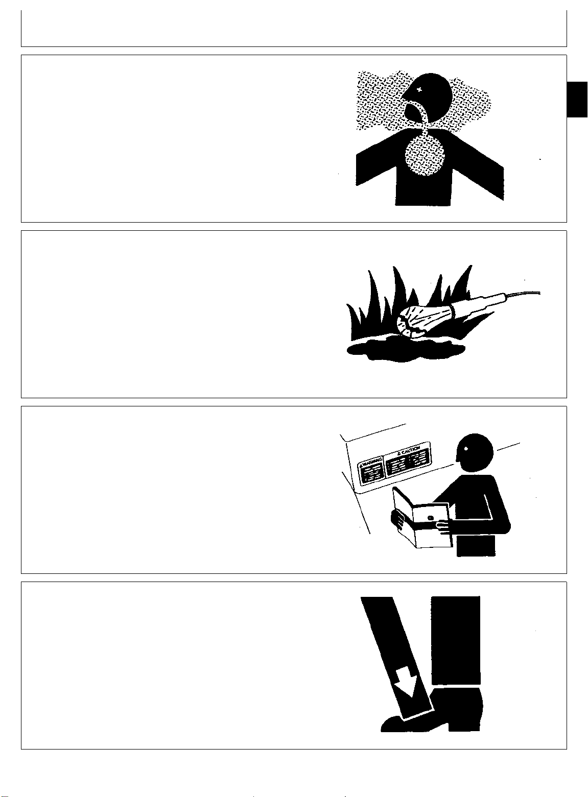
PREVENT ACID BURNS
10
Sulfuric acid in battery electrolyte is poisonous. It is
05
strong enough to burn skin, eat holes in clothing, and
2
cause blindness if splashed into eyes.
Avoid the hazard by:
1. Filling batteries in a well-ventilated area.
2. Wearing eye protection and rubber gloves.
3. Avoiding breathing fumes when electrolyte is added.
4. Avoiding spilling or dripping electrolyte.
5. Use proper jump start procedure.
If you spill acid on yourself:
1. Flush your skin with water.
2. Apply baking soda or lime to help neutralize the acid.
3. Flush your eyes with water for 10—15 minutes. Get
medical attention immediately.
If acid is swallowed:
1. Drink large amounts of water or milk.
2. Then drink milk of magnesia, beaten eggs, or
vegetable oil.
3. Get medical attention immediately.
Safety
DX,POISON -19-04JUN90
TS203 -UN-23AUG88
TM1360 (16OCT91) 10-05-2 55, 56 Series Tractors
010395
Page 9
AVOID HIGH-PRESSURE FLUIDS
Safety
Escaping fluid under pressure can penetrate the skin
causing serious injury.
Avoid the hazard by relieving pressure before
disconnecting hydraulic or other lines. Tighten all
connections before applying pressure.
Search for leaks with a piece of cardboard. Protect
hands and body from high pressure fluids.
If an accident occurs, see a doctor immediately. Any
fluid injected into the skin must be surgically removed
within a few hours or gangrene may result. Doctors
unfamiliar with this type of injury should reference a
knowledgeable medical source. Such information is
available from Deere & Company Medical Department in
Moline, Illinois, U.S.A.
10
05
3
X9811 -UN-23AUG88
PARK MACHINE SAFELY
Before working on the machine:
• Lower all equipment to the ground.
• Stop the engine and remove the key.
• Disconnect the battery ground strap.
• Hang a “DO NOT OPERATE” tag in operator station.
DX,FLUID -19-09AUG91
TS230 -UN-24MAY89
DX,PARK -19-04JUN90
TM1360 (16OCT91) 10-05-3 55, 56 Series Tractors
010395
Page 10
SUPPORT MACHINE PROPERLY
10
Always lower the attachment or implement to the ground
05
before you work on the machine. If you must work on a
4
lifted machine or attachment, securely support the
machine or attachment.
Do not support the machine on cinder blocks, hollow
tiles, or props that may crumble under continuous load.
Do not work under a machine that is supported solely by
a jack. Follow recommended procedures in this manual.
Safety
TS229 -UN-23AUG88
DX,LOWER -19-04JUN90
WEAR PROTECTIVE CLOTHING
Wear close fitting clothing and safety equipment
appropriate to the job.
Prolonged exposure to loud noise can cause impairment
or loss of hearing.
Wear a suitable hearing protective device such as
earmuffs or earplugs to protect against objectionable or
uncomfortable loud noises.
Operating equipment safely requires the full attention of
the operator. Do not wear radio or music headphones
while operating machine.
SERVICE MACHINES SAFELY
Tie long hair behind your head. Do not wear a necktie,
scarf, loose clothing, or necklace when you work near
machine tools or moving parts. If these items were to get
caught, severe injury could result.
TS206 -UN-23AUG88
DX,WEAR -19-10SEP90
Remove rings and other jewelry to prevent electrical
shorts and entanglement in moving parts.
DX,LOOSE -19-04JUN90
TM1360 (16OCT91) 10-05-4 55, 56 Series Tractors
010395
TS228 -UN-23AUG88
Page 11
WORK IN VENTILATED AREA
Safety
Engine exhaust fumes can cause sickness or death. If it
is necessary to run an engine in an enclosed area,
remove the exhaust fumes from the area with an
exhaust pipe extension.
If you do not have an exhaust pipe extension, open the
doors and get outside air into the area.
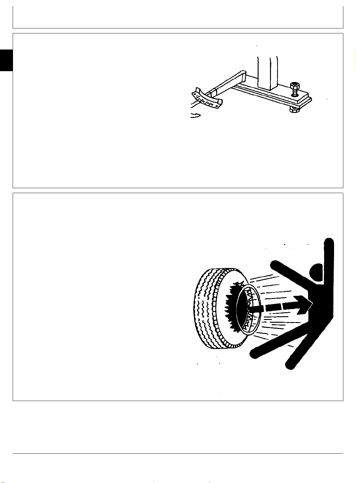
ILLUMINATE WORK AREA SAFELY
Illuminate your work area adequately but safely. Use a
portable safety light for working inside or under the
machine. Make sure the bulb is enclosed by a wire
cage. The hot filament of an accidentally broken bulb
can ignite spilled fuel or oil.
10
05
5
TS220 -UN-23AUG88
DX,AIR -19-04JUN90
TS223 -UN-23AUG88
DX,LIGHT -19-04JUN90
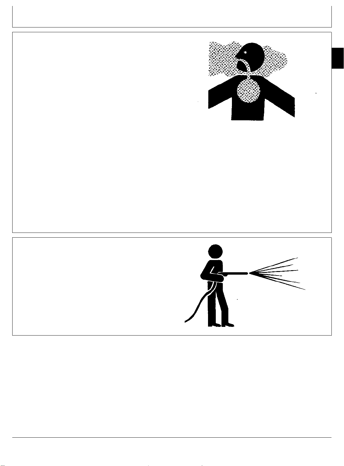
REPLACE SAFETY SIGNS
Replace missing or damaged safety signs. See the
machine operator’s manual for correct safety sign
placement.
USE PROPER LIFTING EQUIPMENT
Lifting heavy components incorrectly can cause severe
injury or machine damage.
Follow recommended procedure for removal and
installation of components in the manual.
TS201 -UN-23AUG88
DX,SIGNS1 -19-04JUN90
DX,LIFT -19-04JUN90
TM1360 (16OCT91) 10-05-5 55, 56 Series Tractors
010395
TS226 -UN-23AUG88
Page 12
KEEP ROPS INSTALLED PROPERLY
10
Make certain all parts are reinstalled correctly if the
05
roll-over protective structure (ROPS) is loosened or
6
removed for any reason. Tighten mounting bolts to
proper torque.
The protection offered by ROPS will be impaired if
ROPS is subjected to structural damage, is involved in
an overturn incident, or is in any way altered by welding,
bending, drilling, or cutting. A damaged ROPS should be
replaced, not reused.
Safety
TS212 -UN-23AUG88
DX,ROPS3 -19-04JUN90
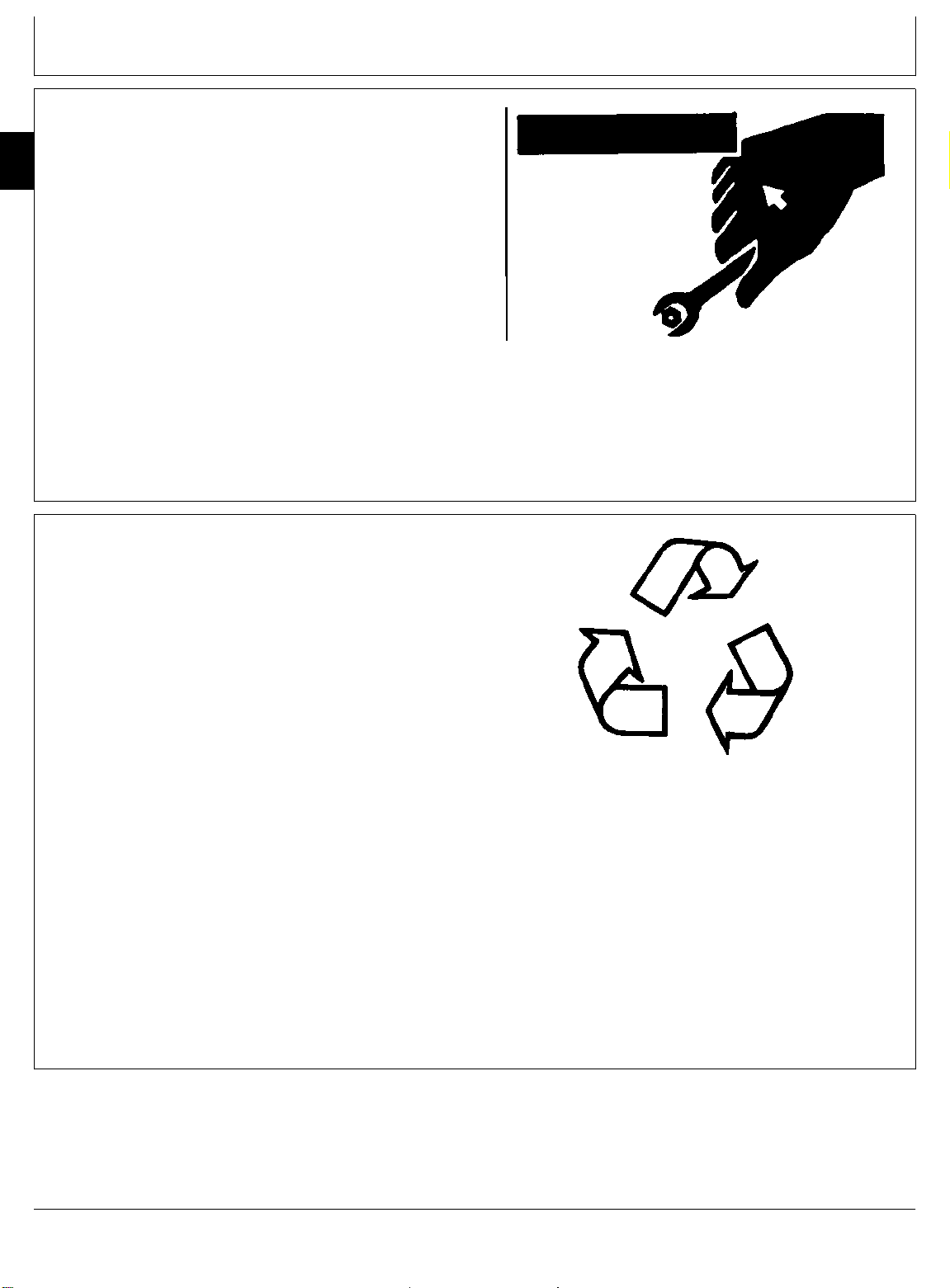
SERVICE TIRES SAFELY
Explosive separation of a tire and rim parts can cause
serious injury or death.
Do not attempt to mount a tire unless you have the
proper equipment and experience to perform the job.
Always maintain the correct tire pressure. Do not inflate
the tires above the recommended pressure. Never weld
or heat a wheel and tire assembly. The heat can cause
an increase in air pressure resulting in a tire explosion.
Welding can structurally weaken or deform the wheel.
When inflating tires, use a clip-on chuck and extension
hose long enough to allow you to stand to one side and
NOT in front of or over the tire assembly. Use a safety
cage if available.
Check wheels for low pressure, cuts, bubbles, damaged
rims or missing lug bolts and nuts.
DX,RIM -19-24AUG90
TM1360 (16OCT91) 10-05-6 55, 56 Series Tractors
010395
TS211 -UN-23AUG88
Page 13
AVOID HARMFUL ASBESTOS DUST
Safety
Avoid breathing dust that may be generated when
handling components containing asbestos fibers. Inhaled
asbestos fibers may cause lung cancer.
Components in products that may contain asbestos fibers
are brake pads, brake band and lining assemblies, clutch
plates, and some gaskets. The asbestos used in these
components is usually found in a resin or sealed in
some way. Normal handling is not hazardous as long as
airborne dust containing asbestos is not generated.
Avoid creating dust. Never use compressed air for
cleaning. Avoid brushing or grinding material containing
asbestos. When servicing, wear an approved respirator.
A special vacuum cleaner is recommended to clean
asbestos. If not available, apply a mist of oil or water on
the material containing asbestos.
Keep bystanders away from the area.
10
05
7
TS220 -UN-23AUG88
WORK IN CLEAN AREA
Before starting a job:
• Clean work area and machine.
• Make sure you have all necessary tools to do your job.
• Have the right parts on hand.
• Read all instructions thoroughly; do not attempt
shortcuts.
DX,DUST -19-15MAR91
T6642EJ -UN-18OCT88
DX,CLEAN -19-04JUN90
TM1360 (16OCT91) 10-05-7 55, 56 Series Tractors
010395
Page 14
USE PROPER TOOLS
10
Use tools appropriate to the work. Makeshift tools and
05
procedures can create safety hazards.
8
Use power tools only to loosen threaded parts and
fasteners.
For loosening and tightening hardware, use the correct
size tools. DO NOT use U.S. measurement tools on
metric fasteners. Avoid bodily injury caused by slipping
wrenches.
Use only service parts meeting John Deere
specifications.
Safety
TS779 -UN-08NOV89
DX,REPAIR -19-04JUN90
DISPOSE OF WASTE PROPERLY
Improperly disposing of waste can threaten the
environment and ecology. Potentially harmful waste used
with John Deere equipment include such items as oil,
fuel, coolant, brake fluid, filters, and batteries.
Use leakproof containers when draining fluids. Do not
use food or beverage containers that may mislead
someone into drinking from them.
Do not pour waste onto the ground, down a drain, or
into any water source.
Air conditioning refrigerants escaping into the air can
damage the Earth’s atmosphere. Government regulations
may require a certified air conditioning service center to
recover and recycle used air conditioning refrigerants.
Inquire on the proper way to recycle or dispose of waste
from your local environmental or recycling center, or from
your John Deere dealer.
TS1133 -UN-26NOV90
DX,DRAIN -19-09AUG91
TM1360 (16OCT91) 10-05-8 55, 56 Series Tractors
010395
Page 15

LIVE WITH SAFETY
Safety
Before returning machine to customer, make sure
machine is functioning properly, especially the safety
systems. Install all guards and shields.
10
05
9
TS231 -19-07OCT88
DX,LIVE -19-04JUN90
TM1360 (16OCT91) 10-05-9 55, 56 Series Tractors
010395
Page 16

10
05
10
Safety
TM1360 (16OCT91) 10-05-10 55, 56 Series Tractors
010395
Page 17

Group 10
Repair Specifications
GENERAL TRACTOR SPECIFICATIONS
ITEM 655 755/756 855/856 955
ENGINE:
Engine Model . . . . . . . . . . . . 3TN66UJ 3TNA72UJ 3TN75RJ 3TN84RJ
Engine Horsepower, Net. . . 16 (11.9 kW) 20 (14.9 kW) 24 (17.9 kW) 33 (24.6 kW)
PTO Horsepower . . . . . . . 10.6 (8.1 kW) 15 (11.2 kW) 19 (14.2 kW) 27 (20.1 kW)
Rated Engine Speed. . . . . . . 3200 rpm 3200 rpm 3200 rpm 3200 rpm
Type . . . . . . . . . . . . . . . . . . . . Diesel Diesel Diesel Diesel
Operating Range . . . . . . .1400-3425 rpm 1400-3425 rpm 1400-3425 rpm 1400-3425 rpm
Number of Cylinders. . . . . . . . . . 3 3 3 3
Displacement . . . . . . . . . . . 40.2 cu. in. 53.6 cu. in. 60.7 cu. in. 87.3 cu. in.
658 cm³ 879 cm³ 995 cm³ 1430 cm³
Bore and Stroke . . . . . . . . .2.59x2.53 in. 2.83x2.83 in. 2.95x2.95 in. 3.31x3.39 in.
(66x64.2 mm) (72x72 mm) (75x75 mm) (84x86 mm)
Compression Ratio. . . . . . . . . 22.4:1 22.3:1 17.8:1 18.0:1
Lubrication . . . . . . . . . . . . . .Pressured Pressured Pressured Pressured
Cooling System. . . . . . . . . . Water-pump Water-pump Water-pump Water-pump
Air Cleaner . . . . . . . . . . . . Dry-Type with Dry-Type with Dry-Type with Dry-Type with
Safety Element Safety Element Safety Element Safety Element
Engine Shutoff . . . . . . . . . . . . . Key Key Key Key
Engine Torque at
Rated Speed. . . . . . . . . . . . . 35 N•m 45 N•m 58 N•m 73 N•m
(26 lb-ft) (33 lb-ft) (39 lb-ft) (54 lb-ft)
10
10
1
ELECTRICAL SYSTEM:
Type . . . . . . . . . . . . . . . . . . . . 12 volt 12 volt 12 volt 12 volt
Battery Size . . . . . . . . . 491 Cold Cranking 491 Cold Cranking 475 Cold Cranking 475 Cold Cranking
Amps @ -18° C Amps @ -18° C Amps @ -18° C Amps @ -18° C
Alternator . . . . . . . . . . . . . . . .35 Amp 35 Amp 35 Amp N/A
40 Amp 40 Amp 40 Amp 40 Amp
Starter Size. . . . . . . . . . . .1.3 hp (1.0 kW) 1.3 hp (1.0 kW) 1.3 hp (1.0 kW) 1.9 hp (1.4 kW)
FUEL SYSTEM:
Type . . . . . . . . . . . . . . . . Indirect Injection Indirect Injection Direct Injection Direct Injection
Injection Pump Type . . . . . . .In-line with In-line with In-line with In-line with
Electric Shutoff Electric Shutoff Electric Shutoff Electric Shutoff
Gallon/hr at 75% load
(mowing). . . . . . . . . . . . . .Not Available 0.86 0.79 1.4
DRIVE TRAIN:
Transmission Type . . . . Hydrostatic-2-range Hydrostatic-2-range Hydrostatic-2-range Hydrostatic-2-range
Transaxle Speed
Ranges . . . . . . . . . . . . . . . . .High/Lo High/Lo High/Lo High/Lo
Number of Speeds . . . . . . . . . Infinite Infinite Infinite Infinite
Final Drive. . . . . . . . . . . . . . . Planetary Planetary Planetary Planetary
Brakes. . . . . . . . . . . . . . . . . . Wet Disk Wet Disk Wet Disk Wet Disk
Steering . . . . . . . . . . . . . . . . . Power Power Power Power
Drawbar Tonque Weight
Capacity . . . . . . . . . . . . .675 lb. (306 kg) 675 lb. (306 kg) 675 lb. (306 kg) 800 lb. (363 kg)
10-10-1
Page 18

Repair Specifications/General Specifications
10
GENERAL SPECIFICATIONS—CONTINUED
10
2
ITEM 655 755/756 855/856 955
HYDRAULIC SYSTEM:
Type of System . . . . . . . . . Open Center Open Center Open Center Open Center
Working Pressure . . . . . . . . . 2050 psi 2050 psi 2050 psi 2500 psi
(14135 kPa) (14135 kPa) (14135 kPa) (17240 kPa)
Pump Type . . . . . . . . . . . . Gerotor Gear Gerotor Gear Gerotor Gear Gerotor Gear
Pump Capacity . . . . . . . . . . . . 4 gpm 5.6 gpm 5.6 gpm 7.2 gpm
(0.25 L/s) (0.35 L/s) (0.35 L/s) (0.45 L/s)
3-PT. Hitch Type . . . . . . .Cat. 1 (Standard) Cat. 1 (Standard) Cat. 1 Cat. 1
Hitch Lift Capacity
(24 in. behind link arms)
Early Models . . . . . . . . . . . . 785 lbs. 785 lbs. 785 lbs. 957 lbs.
(357 kg) (357 kg) (357 kg) (434 kg)
Late Models or Retrofit . . . . . . N/A SN 180250— SN 180450— SN 180525—
N/A 1005 lbs. 1005 lbs. 1177 lbs.
(456 kg) (456 kg) (534 kg)
Lift Control Type . . . . . . . . . Position Position Position Position
PTO:
Type. . . . . . . . . . . . . . . . .Live Independent Live Independent Live Independent Live Independent
Speed (PTO rpm at 3200
engine rpm—full load):
Mid (1:1 gear ratio) . . . . . . . 2100 rpm 2100 rpm 2100 rpm 2100 rpm
Rear (1:3 gear ratio) . . . . . . 540 rpm 540 rpm 540 rpm 540 rpm
Clutch . . . . . . . . . . . . . . . . . . Hydraulic Hydraulic Hydraulic Hydraulic
Multi-Disk Multi-Disk Multi-Disk Multi-Disk
Brake. . . . . . . . . . . . . . . . . .Hydraulically Hydraulically Hydraulically Hydraulically
Controlled Controlled Controlled Controlled
MOWER BLADE TIP SPEED
(at 3200 engine rpm full load):
50 Inch Mower. . . . . . . . . . 15,371 ft/min N/A N/A N/A
(4688 m/min)
1:1.04 Gear Ratio . . . . .Spindle rpm 3389 N/A N/A N/A
60 Inch Mower. . . . . . . . . . . . . . N/A 15,471 ft/min 15,471 ft/min 15,471 ft/min
(4719 m/min) (4719 m/min) (4719 m/min)
1:1 Gear Ratio. . . . . . . . . . . . . N/A Spindle rpm 2883 Spindle rpm 2883 Spindle rpm 2883
72 Inch Mower. . . . . . . . . . . . . . N/A 15,167 ft/min 15,167 ft/min 15,167 ft/min
(4626 m/min) (4626 m/min) (4626 m/min)
1:1 Gear Ratio. . . . . . . . . . . . . N/A Spindle rpm 2321 Spindle rpm 2321 Spindle rpm 2321
261 Inch Mower. . . . . . . . . . . . . N/A 14,465 ft/min 14,465 ft/min 14,465 ft/min
(4412 m/min) (4412 m/min) (4412 m/min)
1:3 Gear Ratio. . . . . . . . . . . . . N/A Spindle rpm 2695 Spindle rpm 2695 Spindle rpm 2695
272 Inch Mower. . . . . . . . . . . . . N/A 14,601 ft/min 14,601 ft/min 14,601ft/min
(4453 m/min) (4453 m/min) (4453 m/min)
1:3 Gear Ratio. . . . . . . . . . . . . N/A Spindle rpm 2234 Spindle rpm 2234 Spindle rpm 2234
10-10-2
Page 19

Repair Specifications/General Specifications
GENERAL SPECIFICATIONS—CONTINUED
ITEM 655 755/756 855/856 955
FLUID CAPACITIES:
Fuel Tank . . . . . . . . . . . 3.95 U.S. gal (15 L) 4.4 U.S. gal (16.7 L) 6.6 U.S. gal (25 L) 6.6 U.S. gal (25 L)
Cooling System. . . . . . . . 4 U.S. qt. (3.8 L) 4 U.S. qt. (3.8 L) 4.8 U.S. qt. (4.5 L) 4.8 U.S. qt. (4.5 L)
Crankcase (w/filter). . . . .2.5 U.S. qt. (2.4 L) 2.86 U.S. qt. (2.7 L) 4.1 U.S. qt. (3.9 L) 4.4 U.S. qt. (4.2 L)
Transmission and
Hydraulic System . . . . 4.5 U.S. gal. (17 L) 4.5 U.S. gal. (17 L) 4.5 U.S. gal. (17 L) 4.5 U.S. gal. (17 L)
MFWD Gear Case . . . .2.25 U.S. qt. (2.13 L) 2.25 U.S. qt. (2.13 L) 2.25 U.S. qt. (2.13 L) 3.5 U.S. qt. (3.3 L)
WEIGHT (includes fuel, oil, coolant and R-1 tires):
2WD . . . . . . . . . . . . . . . . . . . 1584 lbs. 1700 lbs. 1790 lbs. N/A
(718 kg) (771 kg) (812 kg)
MFWD. . . . . . . . . . . . . . . . . . 1680 lbs. 1835 lbs. 1870 lbs. 1990 lbs.
(762 kg) (832 kg) (848 kg) (903 kg)
SERVICE INTERVALS:
Engine
Valve Adjustment . . . . . . . . .300 Hours 300 Hours 300 Hours 300 Hours
Primary Filter . . . . . . . . . . . .400 Hours 400 Hours 400 Hours 400 Hours
or every two years
10
10
3
Secondary Filter . . . . . . . Every two years Every two years Every two years Every two years
or when every third primary filter is installed
GROUND SPEEDS (at full engine rpm):
Forward High Range. . . . . .0—10.0 mph 0—10.6 mph 0—11.0 mph 0—11.4 mph
(0—16.1 K/hr) (0—17.1 K/hr) (0—17.7 K/hr) (0—18.3 K/hr)
Forward Lo Range . . . . . . .0—05.4 mph 0—05.8 mph 0—06.0 mph 0—05.1 mph
(0—08.7 K/hr) (0—09.3 K/hr) (0—09.7 K/hr) (0—08.2 K/hr)
Reverse High And Lo . . . . .0—05.0 mph 0—05.3 mph 0—05.5 mph 0—05.7 mph
(0—08.1 K/hr) (0—08.5 K/hr) (0—08.9 K/hr) (0—09.2 K/hr)
ENGINE COOLANT HEATER:
Current Draw Current Draw Current Draw Current Draw
400 Watts 400 Watts 400 Watts 400 Watts
SPARK ARRESTER:
Not Available Available Available Available
10-10-3
Page 20

10
10
4
Repair Specifications/General Specifications
TM1360 (16OCT91) 10-10-4 55, 56 Series Tractors
010395
Page 21
Group 15
Repair Information
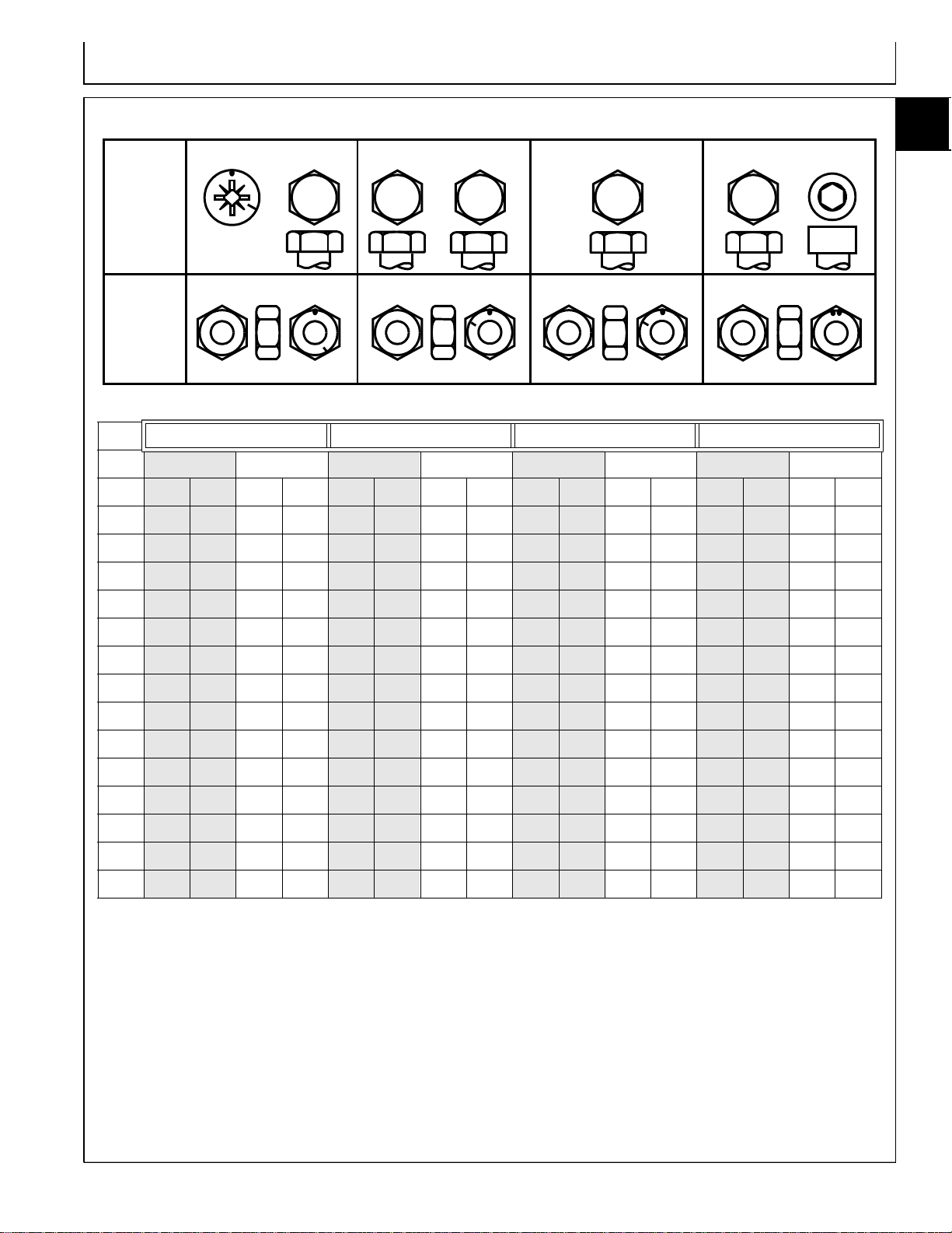
METRIC FASTENER TORQUE VALUES
12.9
12.9
12
12.9
12.9
12
12
a
Dry
a
4.8
8.8
9.8
10.9
Property
Class
and
Head
Markings
Property
4.8
4.8
8.8
8.8
5
9.8
9.8
10
10.9
10.9
10
Class
and
Nut
Markings
Class 4.8 Class 8.8 or 9.8 Class 10.9 Class 12.9
Lubricated
SIZE N•m lb-ft N•m lb-ft N•m lb-ft N•m lb-ft N•m lb-ft N•m lb-ft N•m lb-ft N•m lb-ft
M6
M8
48 3.5 6 4.5 9 6.5 11 8.5 13 9.5 17 12 15 11.5 19 14.5
12 8.5 15 11 22 16 28 20 32 24 40 30 37 28 47 35
510
a
Dry
5
a
Lubricated
a
Dry
10
a
10
Lubricated
10
a
Dry
a
Lubricated
10
15
1
TS1163
M10
M12
M14
M16
M18
M20
M22
M24
M27
M30
M33
M36
23 17 29 21 43 32 55 40 63 47 80 60 75 55 95 70
40 29 50 37 75 55 95 70 110 80 140 105 130 95 165 120
63 47 80 60 120 88 150 110 175 130 225 165 205 150 260 109
100 73 125 92 190 140 240 175 275 200 350 225 320 240 400 300
135 100 175 125 260 195 330 250 375 275 475 350 440 325 560 410
190 140 240 180 375 275 475 350 530 400 675 500 625 460 800 580
260 190 330 250 510 375 650 475 725 540 925 675 850 625 1075 800
330 250 425 310 650 475 825 600 925 675 1150 850 1075 800 1350 1000
490 360 625 450 950 700 1200 875 1350 1000 1700 1250 1600 1150 2000 1500
675 490 850 625 1300 950 1650 1200 1850 1350 2300 1700 2150 1600 2700 2000
900 675 1150 850 1750 1300 2200 1650 2500 1850 3150 2350 2900 2150 3700 2750
1150 850 1450 1075 2250 1650 2850 2100 3200 2350 4050 3000 3750 2750 4750 3500
DO NOT use these hand torque values if a different
torque value or tightening procedure is given for a
specific application. Torque values listed are for general
use only and include a ±10% variance factor. Check
tightness of fasteners periodically. DO NOT use air
powered wrenches.
Shear bolts are designed to fail under predetermined
loads. Always replace shear bolts with identical grade.
Fasteners should be replaced with the same grade.
Make sure fastener threads are clean and that you
properly start thread engagement. This will prevent
them from failing when tightening.
When bolt and nut combination fasteners are used,
torque values should be applied to the NUT instead of
the bolt head.
Tighten toothed or serrated-type lock nuts to the full
torque value.
a
“Lubricated” means coated with a lubricant such as
engine oil, or fasteners with phosphate and oil coatings. “Dry” means plain or zinc plated (yellow dichromate - Specification JDS117) without any lubrication
.
Reference: JDS—G200.
10-15-1
Page 22
Repair Information/Metric Cap Screw Torque Values
10
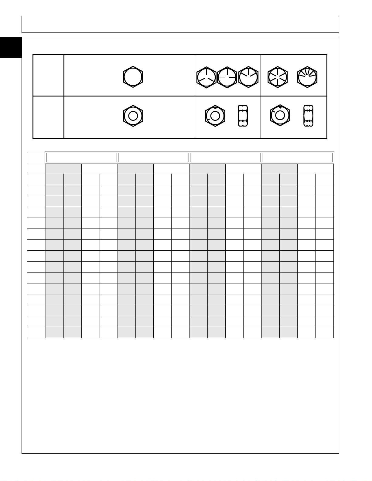
INCH FASTENER TORQUE VALUES
15
2
SAE
Grade
and Head
Markings
No Marks
1 or 2
b
5
5.1
5.2
8
8.2
2
5
8
SAE
Grade
and Nut
No Marks
Markings
TS1 162
Grade 1 Grade 2
Lubricated
SIZE N•m lb-ft N•m lb-ft N•m lb-ft N•m lb-ft N•m lb-ft N•m lb-ft N•m lb-ft N•m lb-ft
1/4
5/16
3/8
7/16
1/2
9/16
5/8
3/4
3.7 2.8 4.7 3.5 6 4.5 7.5 5.5 9.5 712913.5 10 17 12.5
7.7 5.5 10 7 12 9151120 15 25 18 28 21 35 26
14 10 17 13 22 16 27 20 35 26 44 33 50 36 63 46
22 16 28 20 35 26 44 32 55 41 70 52 80 58 100 75
33 25 42 31 53 39 67 50 85 63 110 80 120 90 150 115
48 36 60 45 75 56 95 70 125 90 155 115 175 130 225 160
67 50 85 62 105 78 135 100 170 125 215 160 215 160 300 225
120 87 150 110 190 140 240 175 300 225 375 280 425 310 550 400
a
Dry
a
b
Lubricated
Grade 5, 5.1 or 5.2 Grade 8 or 8.2
a
Dry
a
Lubricated
a
Dry
a
Lubricated
a
Dry
a
7/8
1
1-1/8
1-1/4
1-3/8
1-1/2
190 140 240 175 190 140 240 175 490 360 625 450 700 500 875 650
290 210 360 270 290 210 360 270 725 540 925 675 1050 750 1300 975
470 300 510 375 470 300 510 375 900 675 1150 850 1450 1075 1850 1350
570 425 725 530 570 425 725 530 1300 950 1650 1200 2050 1500 2600 1950
750 550 950 700 750 550 950 700 1700 1250 2150 1550 2700 2000 3400 2550
1000 725 1250 925 990 725 1250 930 2250 1650 2850 2100 3600 2650 4550 3350
DO NOT use these hand torque values if a different
torque value or tightening procedure is given for a
specific application. Torque values listed are for general
use only and include a ±10% variance factor. Check
tightness of fasteners periodically. DO NOT use air
powered wrenches.
Shear bolts are designed to fail under predetermined
loads. Always replace shear bolts with identical grade.
Fasteners should be replaced with the same grade.
Make sure fastener threads are clean and that you
properly start thread engagement. This will prevent
them from failing when tightening.
When bolt and nut combination fasteners are used,
torque values should be applied to the NUT instead of
the bolt head.
Tighten toothed or serrated-type lock nuts to the full
torque value.
a
“Lubricated” means coated with a lubricant such as
engine oil, or fasteners with phosphate and oil coatings. “Dry” means plain or zinc plated (yellow dichro-
.
mate - Specification JDS117) without any lubrication
b
“Grade 2” applies for hex cap screws (not hex
bolts) up to 152 mm (6-in.) long. “Grade 1”
applies for hex cap screws over 152 mm (6-in.)
long, and for all other types of bolts and screws
of any length.
Reference: JDS—G200.
10-15-2
Page 23
Service Recommendations/O-Ring Face Seal Fittings
SERVICE RECOMMENDATIONS
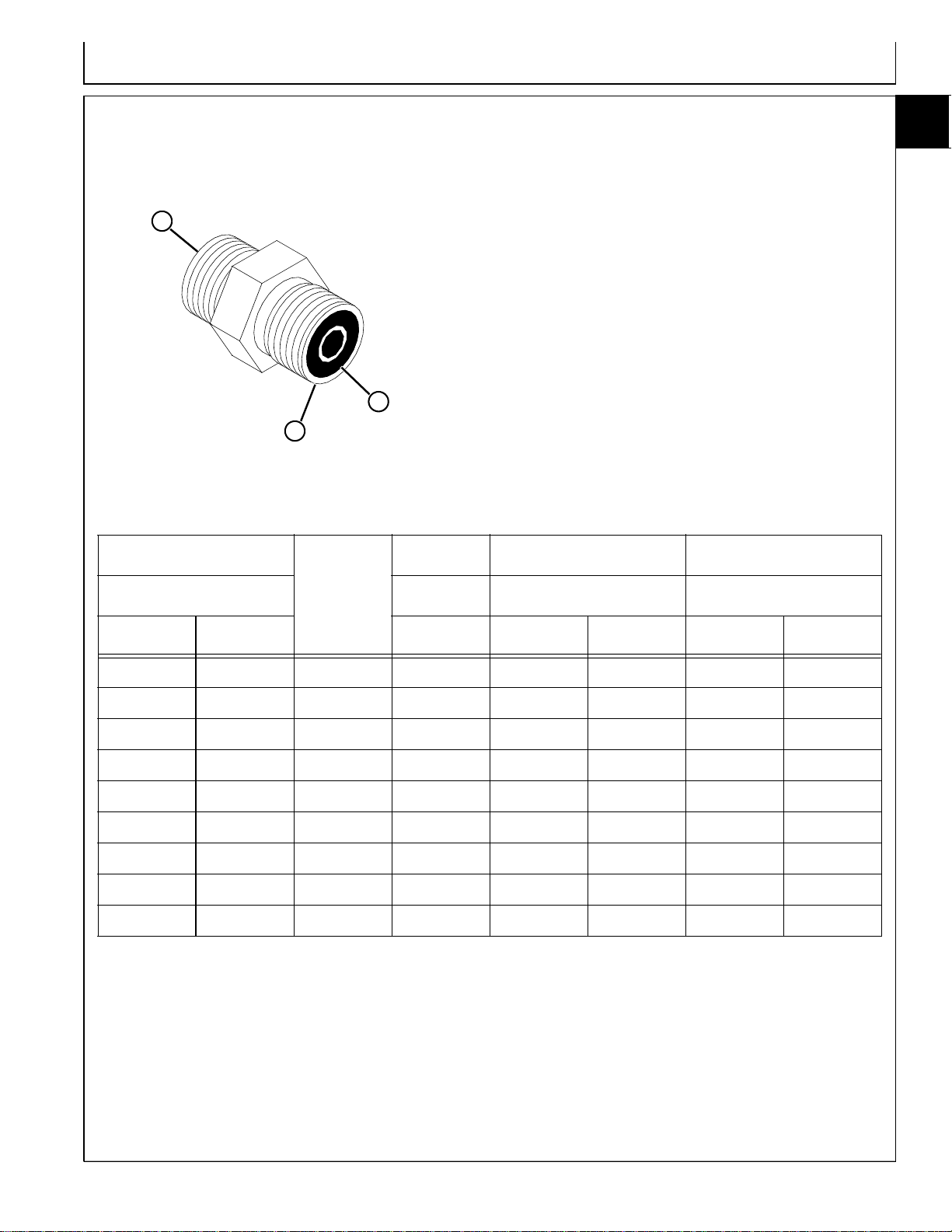
O-RING FACE SEAL FITTINGS
A
A
O-RING FACE SEAL FITTING INCH TORQUE
10
15
3
1. Inspect the fitting sealing surfaces (A). They must be
free of dirt or defects.
2. Inspect the O-ring (B). It must be free of damage or
defects.
3. Lubricate O-rings and install into groove using
petroleum jelly to hold in place.
4. Push O-ring into the groove with plenty of petroleum
jelly so O-ring is not displaced during assembly.
5. Index angle fittings and tighten by hand pressing joint
together to insure O-ring remains in place.
6. Tighten fitting or nut to torque value shown on the
chart per dash size stamped on the fitting. Do not
allow hoses to twist when tightening fittings.
B
NOMINAL
Tube O.D. Size Torque Nut Torque
Dash
Size
THREAD SWIVEL NUT BULKHEAD
mm in. in. N•m lb-ft N•m lb-ft
6.35 0.250 -4 9/16-18 16 12 5.0 3.5
9.52 0.375 -6 11/16-16 24 18 9.0 6.5
12.70 0.500 -8 13/16-16 50 37 17.0 12.5
15.88 0.625 -10 1-14 69 51 17.0 12.5
19.05 0.750 -12 1 3/16-12 102 75 17.0 12.5
22.22 0.875 -14 1 3/16-12 102 75 17.0 12.5
25.40 1.000 -16 1 7/16-12 142 105 17.0 12.5
31.75 1.250 -20 1 11/16-12 190 140 17.0 12.5
38.10 1.500 -24 2-12 217 160 17.0 12.5
NOTE: Torque tolerance is + 15 -20%.
10-15-3
Page 24
Service Recommendations/O-Ring Boss Fittings
10
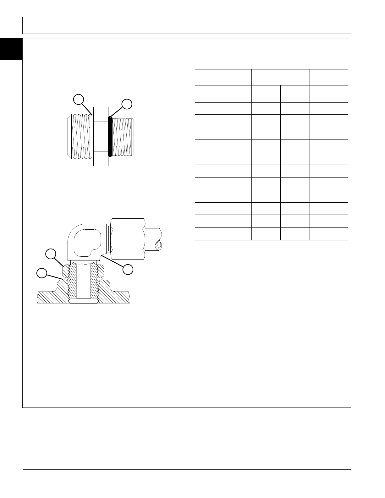
O-RING BOSS FITTINGS
15
4
1. Inspect boss O-ring boss seat. It must be free of dirt
and defects. If repeated leaks occur, inspect for
defects with a magnifying glass. Some raised defects
can be removed with a slip stone.
A
B
STRAIGHT FITTING OR SPECIAL NUT TORQUE
Thread Torque
a
Number
Size N•m lb-ft of Flats
3/8-24 UNF 8 (6) 2
7/16-20 UNF 12 (9) 2
1/2-20 UNF 16 (12) 2
9/16-18 UNF 24 (18) 2
3/4-16 UNF 46 (34) 2
7/8-14 UNF 62 (46) 1-1/2
b
2. Put hydraulic oil or petroleum jelly on the O-ring (B).
Place electrical tape over the threads to protect Oring from nicks. Slide O-ring over the tape and into
the groove (A) of fitting. Remove tape.
E
D
C
3. For angle fittings (C), loosen special nut (E) and push
special washer (D) against threads so O-ring can
be installed into the groove of fitting.
4. Turn fitting into the boss by hand until special washer
or washer face (straight fitting) contacts boss face
and O-ring is squeezed into its seat.
5. To position angle fittings, turn the fitting counterclockwise a maximum of one turn.
6. Tighten straight fittings to torque value shown on
chart. For angle fittings, tighten the special nut to
value shown in the chart while holding body of fitting
with a wrench.
1-1/16-12 UN 102 (75) 1
1-3/16-12 UN 122 (90) 1
1-5/16-12 UN 142 (105) 3/4
1-5/8-12 UN 190 (140) 3/4
1-7/8-12 UN 217 (160) 1/2
a. Torque tolerance is ± 10 percent.
b. To be used if a torque wrench cannot be used.
After tightening fitting by hand, put a mark on nut or
boss; then tighten special nut or straight fitting the
number of flats shown.
10-15-4
Page 25

Group 20
Fuels, Lubricants, and Coolants
DIESEL FUEL - NORTH AMERICA
In general, diesel fuels are blended to satisfy the low air
temperature requirements of the geographical area in
which they are sold.
In North America, diesel fuel is usually specified to
ASTM D975 and sold as either Grade 1 for cold air
temperatures or Grade 2 for warm air temperatures.
If diesel fuels being supplied in your area DO NOT meet
any of the above specifications, use diesel fuels with the
following equivalent properties:
•Cetane Number 40 (minimum)
A cetane number greater than 50 is preferred,
especially for air temperatures below –20°C (–4°F) or
elevations above 1500 m (5000 ft).
•Cold Filter Plugging Point (CFPP)
The air temperature at which diesel fuel begins to
cloud or jell — at least 5°C (9°F) below the expected
low air temperature range.
•Sulfur Content of 0.05%
Diesel fuels for highway use in the United States now
require sulfur content to be less than 0.05%.
If diesel fuel being used has a sulfur content greater
than 0.05%, reduce the service interval for engine
oil and filter by 50%.
Consult your local diesel fuel distributor for properties of
the diesel fuel available in your area.
c
California Proposition 65 Warning: Diesel engine
exhaust and some of its elements from this
product are known to the State of California to
cause cancer, birth defects, or other
reproductive harm.
WARNING
10
20
1
DIESEL FUEL LUBRICITY
Diesel fuel must have adequate lubricity to ensure
proper operation and durability of fuel injection system
components. Fuel lubricity should pass a minimum of
3300 gram load level as measured by the BOCLE
scuffing test.
DIESEL FUEL STORAGE
IMPORTANT: DO NOT USE GALVANIZED
CONTAINERS—diesel fuel stored in
galvanized containers reacts with zinc
coating in the container to form zinc
flakes. If fuel contains water, a zinc
gel will also form. The gel and flakes
will quickly plug fuel filters and
damage fuel injectors and fuel
pumps.
It is recommended that diesel fuel be stored ONLY in a
clean, approved POLYETHYLENE PLASTIC container
WITHOUT any metal screen or filter. This will help
prevent any accidental sparks from occurring. Store fuel
in an area that is well ventilated to prevent possible
igniting of fumes by an open flame or spark, this
includes any appliance with a pilot light.
IMPORTANT: Keep all dirt, scale, water or other
foreign material out of fuel.
Keep fuel in a safe, protected area and in a clean,
properly marked (“DIESEL FUEL”) container. DO NOT
use deicers to attempt to remove water from fuel. DO
NOT depend on fuel filters to remove water from fuel. It
is recommended that a water separator be installed in
the storage tank outlet. BE SURE to properly discard
unstable or contaminated diesel fuel and/or their
containers when necessary.
10-20-1
Page 26

Fuels, Lubricants, and Coolants/Hydraulic/Transmission Oil
10
DIESEL FUEL - EUROPE
20
2
In general, diesel fuels are blended to satisfy the low air
temperature requirements of the geographical area in
which they are sold.
In Europe, diesel fuel is usually specified to EN590 and
sold in 5 different classes or 6 different grades.
If diesel fuels being supplied in your area DO NOT meet
any of the above specifications, use diesel fuels with the
following equivalent properties:
•Cetane Number 40 (minimum)
A cetane number greater than 50 is preferred,
especially for air temperatures below –20°C (–4°F) or
elevations above 1500 m (5000 ft).
If diesel fuel being used has a sulfur content greater
than 0.05%, reduce the service interval for engine
oil and filter by 50%.
Consult your local diesel fuel distributor for properties of
the diesel fuel available in your area.
•Cold Filter Plugging Point (CFPP)
The air temperature at which diesel fuel begins to
cloud or jell — at least 5°C (9°F) below the expected
low air temperature range.
•Sulfur Content of 0.05%
Diesel fuel for highway use in the European Union
will be required to have a sulfur content of less than
0.05% by 1 October 1996.
If diesel fuel being used has a sulfur content greater
than 0.05%, reduce the service interval for engine
oil and filter by 50%.
Consult your local diesel fuel distributor for properties of
the diesel fuel available in your area.
DIESEL FUEL LUBRICITY
Diesel fuel must have adequate lubricity to ensure
proper operation and durability of fuel injection system
components. Fuel lubricity should pass a minimum of
3300 gram load level as measured by the BOCLE
scuffing test.
DIESEL FUEL STORAGE
IMPORTANT: DO NOT USE GALVANIZED
CONTAINERS—diesel fuel stored in
galvanized containers reacts with zinc
coating in the container to form zinc
flakes. If fuel contains water, a zinc
gel will also form. The gel and flakes
will quickly plug fuel filters and
damage fuel injectors and fuel
pumps.
It is recommended that diesel fuel be stored ONLY in a
clean, approved POLYETHYLENE PLASTIC container
WITHOUT any metal screen or filter. This will help
prevent any accidental sparks from occurring. Store fuel
in an area that is well ventilated to prevent possible
igniting of fumes by an open flame or spark, this
includes any appliance with a pilot light.
IMPORTANT: Keep all dirt, scale, water or other
foreign material out of fuel.
Keep fuel in a safe, protected area and in a clean,
properly marked (“DIESEL FUEL”) container. DO NOT
use deicers to attempt to remove water from fuel. DO
NOT depend on fuel filters to remove water from fuel. It
is recommended that a water separator be installed in
the storage tank outlet. BE SURE to properly discard
unstable or contaminated diesel fuel and/or their
containers when necessary.
10-20-2
Page 27
Fuels, Lubricants, and Coolants/Hydraulic/Transmission Oil
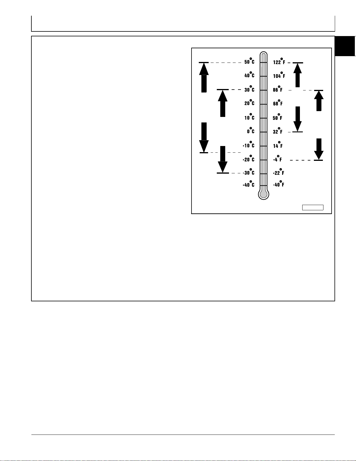
4–CYCLE DIESEL ENGINE OIL - NORTH
AMERICA
Use appropriate oil viscosity based on the expected air
temperature range during the period between
recommended oil changes. Operating outside of these
recommended oil air temperature ranges may cause
premature engine failure.
The following John Deere oils are PREFERRED:
•PLUS–50®—SAE 15W-40;
•TORQ–GARD SUPREME®—SAE 5W-30.
The following John Deere oils are also recommended,
based on their specified temperature range:
•TURF–GARD®—SAE 10W-30;
•PLUS–4®—SAE 10W-30;
•TORQ–GARD SUPREME®—SAE 30.
Other oils may be used if above John Deere oils are not
available, provided they meet one of the following
specifications:
•SAE 15W-40 (preferred)—API Service Classifications
CG–4 or CF–4 or higher;
•SAE 5W-30 (preferred)—API Service Classification CD
or CC or higher;
•SAE 10W-30—API Service Classification CF–4 or CF
or higher;
•SAE 30—API Service Classification CF–4 or CF or
higher.
IMPORTANT: If diesel fuel with sulfur content
greater than 0.5% is used, reduce the
service interval for oil and filter by
50%.
SAE 30
SAE 15W-40
SAE10W-30
SAE 5W-30
PREFERRED
AIR TEMPERATURE
M58275
John Deere Dealers: You may want to cross-reference
the following publications to recommend the proper oil
for your customers:
•Module DX, ENOIL in JDS–G135;
•Section 530, Lubricants & Hydraulics, of the John
Deere Merchandise Sales Guide;
•Lubrication Sales Manual PI7032.
10
20
3
10-20-3
Page 28
Fuels, Lubricants, and Coolants/Hydraulic/Transmission Oil
10
4–CYCLE DIESEL ENGINE OIL - EUROPE
20
4
Use appropriate oil viscosity based on the expected air
temperature range during the period between
recommended oil changes. Operating outside of these
recommended oil air temperature ranges may cause
premature engine failure.
The following John Deere oils are PREFERRED:
•TORQ–GARD SUPREME®—SAE 15W-40;
•UNI–GARD™—SAE 15W-40;
•TORQ–GARD SUPREME®—SAE 5W-30;
•UNI–GARD™—SAE 5W-30.
The following John Deere oils are also recommended,
based on their specified temperature range:
•TORQ–GARD SUPREME®—SAE 10W-30;
•UNI–GARD™—SAE 10W-30;
•TORQ–GARD SUPREME®—SAE 30;
•UNI–GARD™—SAE 30.
Other oils may be used if above John Deere oils are not
available, provided they meet one of the following
specifications:
•CCMC Specification D5 or Mercedes Benz MB228.3 or
higher;
•CCMC Specification D4 or Mercedes Benz MB228.1 or
higher .
IMPORTANT: If diesel fuel with sulfur content
greater than 0.5% is used, reduce the
service interval for oil and filter by
50%.
SAE 30
SAE 15W-40
SAE10W-30
SAE 5W-30
PREFERRED
AIR TEMPERATURE
M58275
John Deere Dealers: You may want to cross-reference
the following publications to recommend the proper oil
for your customers:
•Module DX,ENOIL in JDS–G135;
•Section 530, Lubricants & Hydraulics, of the John
Deere Merchandise Sales Guide.
10-20-4
Page 29
Fuels, Lubricants, and Coolants/Hydraulic/Transmission Oil
BREAK–IN DIESEL ENGINE OIL NORTH AMERICA
IMPORT ANT: ONLY use this specified break-in oil in
rebuilt or remanufactured engines for
the first 100 hours maximum. DO NOT
use PLUS–50®, SAE 15W40 oil or oils
meeting specifications API CG–4 or
API CF–4, these oils will not allow
rebuilt or remanufactured engines to
break-in properly.
The following John Deere oil is PREFERRED:
•BREAK–IN ENGINE OIL.
John Deere BREAK–IN ENGINE OIL is formulated
with special additives for aluminum and cast iron type
engines to allow the power cylinder components
(pistons, rings, and liners as well) to “wear-in” while
protecting other engine components, valve train and
gears, from abnormal wear. Engine rebuild instructions
should be followed closely to determine if special
requirements are necessary.
John Deere BREAK–IN ENGINE OIL is also
recommended for non-John Deere engines, both
aluminum and cast iron types.
If this preferred John Deere oil is not available, use a
break-in engine oil meeting the following specification
during the first 100 hours of operation:
•API Service Classification CE.
After the break-in period, use the John Deere oil that is
recommended for this engine.
BREAK-IN OIL
AIR TEMPERATURE
M58275
John Deere Dealers: You may want to cross-reference
the following publications to recommend the proper oil
for your customers:
•Module DX,ENOIL4 in JDS–G135;
•Section 530, Lubricants & Hydraulics, of the John
Deere Merchandise Sales Guide;
•Lubrication Sales Manual PI7032.
10
20
5
10-20-5
Page 30
Fuels, Lubricants, and Coolants/Hydraulic/Transmission Oil
10
BREAK–IN DIESEL ENGINE OIL - EUROPE
20
6
IMPORT ANT: ONLY use this specified break-in oil in
rebuilt or remanufactured engines for
the first 100 hours maximum. DO NOT
use SAE 15W-40 oil or oils meeting
CCMC Specification D5—these oils
will not allow rebuilt or
remanufactured engines to break-in
properly.
The following John Deere oil is PREFERRED:
•BREAK–IN ENGINE OIL.
John Deere BREAK–IN ENGINE OIL is formulated
with special additives for aluminum and cast iron type
engines to allow the power cylinder components
(pistons, rings, and liners as well) to “wear-in” while
protecting other engine components, valve train and
gears, from abnormal wear. Engine rebuild instructions
should be followed closely to determine if special
requirements are necessary.
John Deere BREAK–IN ENGINE OIL is also
recommended for non-John Deere engines, both
aluminum and cast iron types.
If above preferred John Deere oil is not available, use a
break-in engine oil meeting the following specification
during the first 100 hours of operation:
•CCMC Specification D4.
After the break-in period, use the John Deere oil that is
recommended for this engine.
BREAK-IN OIL
AIR TEMPERATURE
M58275
John Deere Dealers: You may want to cross-reference
the following publications to recommend the proper oil
for your customers:
•Module DX, ENOIL4 in JDS–G135;
•Section 530, Lubricants & Hydraulics, of the John
Deere Merchandise Sales Guide.
10-20-6
Page 31

Fuels, Lubricants, and Coolants/Hydraulic/Transmission Oil
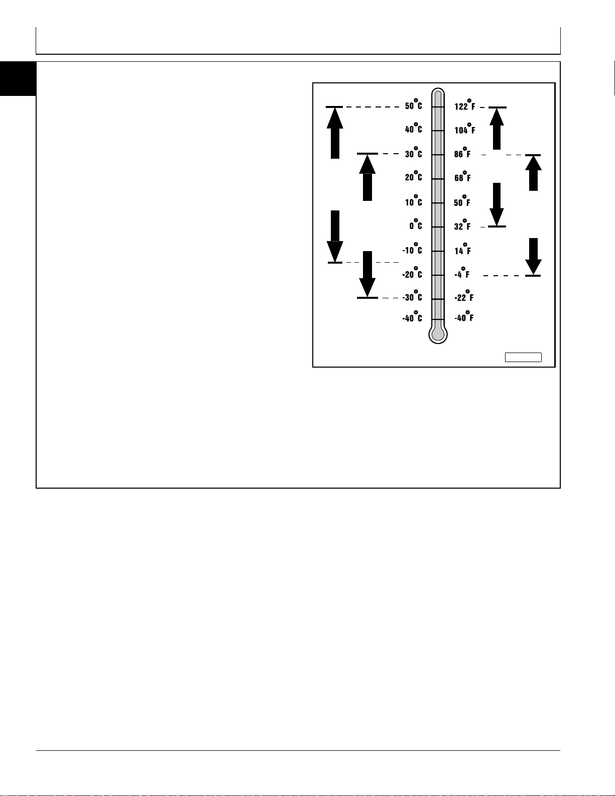
HYDROSTATIC TRANSMISSION AND
HYDRAULIC OIL - NORTH AMERICA
Use the appropriate oil viscosity based on these air
temperature ranges. Operating outside of these
recommended oil air temperature ranges may cause
premature transmission or hydraulic system failures.
IMPORTANT: Mixing of LOW VISCOSITY HY–
GARD® and HY–GARD® oils is
permitted. DO NOT mix any other oils
in this transmission. DO NOT use
engine oil or “Type F” (Red)
Automatic Transmission Fluid in this
transmission. DO NOT use BIO–HY–
GARD® in this transmission.
The following John Deere transmission and hydraulic oil
is PREFERRED:
•LOW VISCOSITY HY–GARD®—JDM J20D.
The following John Deere oil is also recommended if
above preferred oil is not available:
•HY–GARD®—JDM J20C.
Other oils may be used if above recommended John
Deere oils are not available, provided they meet one of
the following specifications:
•John Deere Standard JDM J20D (preferred);
•John Deere Standard JDM J20C.
IMPORTANT: When using HY–GARD® (JDM J20C),
if the minimum air temperature
should fall below -7°C (-20°F) drain
reservoir and switch to LOW
VISCOSITY HY–GARD® (JDM J20D). If
minimum air temperature should fall
below -40°C (-40°F), the transmission
oil must be heated to at least five
degrees above the lower limit before
start-up or transmission may be
damaged. For prolonged operation
under heavy load in air temperatures
above 50°C (122°F) reduce service
interval by 50%.
JDM J20C
JDM J20D
PREFERRED
AIR TEMPERATURE
M58275
John Deere Dealers: You may want to cross-reference
the following publications to recommend the proper oil
for your customers:
•Module DX,ANTI in JDS–G135;
•Section 530, Lubricants & Hydraulics, of the John
Deere Merchandise Sales Guide;
•Lubrication Sales Manual PI7032.
NOTE: Disregard the John Deere All Weather
Hydrostatic Fluid (JDM J21A) listing—it has
been eliminated from the specifications.
10
20
7
10-20-7
Page 32

Fuels, Lubricants, and Coolants/Hydraulic/Transmission Oil
10
HYDROSTATIC TRANSMISSION AND
20
8
HYDRAULIC OIL - EUROPE
Use the appropriate oil viscosity based on these air
temperature ranges. Operating outside of these
recommended oil air temperature ranges may cause
premature transmission or hydraulic system failures.
IMPORTANT: Mixing of LOW VISCOSITY HY–
GARD® and HY–GARD® oils is
permitted. DO NOT mix any other oils
in this transmission. DO NOT use
engine oil or “Type F” (Red)
Automatic Transmission Fluid in this
transmission. DO NOT use BIO–HY–
GARD® in this transmission.
The following John Deere transmission and hydraulic oil
is PREFERRED:
•LOW VISCOSITY HY–GARD®—JDM J20D.
The following John Deere oil is also recommended if
above preferred oil is not available:
•HY–GARD®—JDM J20C.
JDM J20D
PREFERRED
AIR TEMPERATURE
JDM J20C
M58275
Other oils may be used if above recommended John
Deere oils are not available, provided they meet one of
the following specifications:
•John Deere Standard JDM J20D (preferred);
•John Deere Standard JDM J20C.
IMPORTANT: When using HY–GARD® (JDM J20C),
if the minimum air temperature
should fall below -7°C (-20°F) drain
reservoir and switch to LOW
VISCOSITY HY–GARD® (JDM J20D). If
minimum air temperature should fall
below -40°C (-40°F), the transmission
oil must be heated to at least five
degrees above the lower limit before
start-up or transmission may be
damaged. For prolonged operation
under heavy load in air temperatures
above 50°C (122°F) reduce service
interval by 50%.
John Deere Dealers: You may want to cross-reference
the following publications to recommend the proper oil
for your customers:
•Module DX, ANTI in JDS–G135;
•Section 530, Lubricants & Hydraulics, of the John
Deere Merchandise Sales Guide.
NOTE: Disregard the John Deere All Weather
Hydrostatic Fluid (JDM J21A) listing—it has
been eliminated from the specifications.
10-20-8
Page 33

Fuels, Lubricants, and Coolants/Hydraulic/Transmission Oil
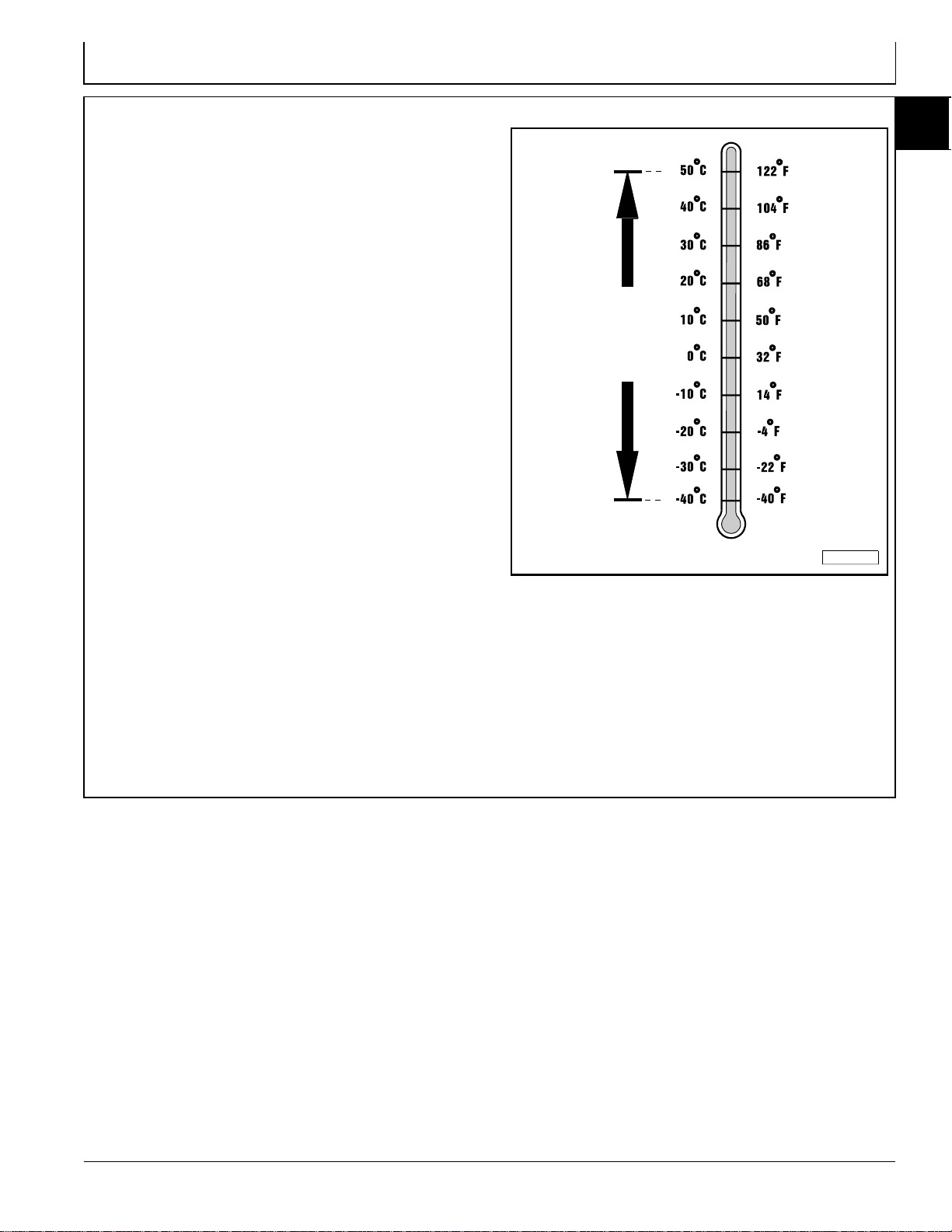
GEAR CASE OIL - NORTH AMERICA
MECHANICAL FRONT WHEEL DRIVE
Use the following oil viscosity based on the air
temperature range. Operating outside of the
recommended oil air temperature range may cause
premature gear case failure.
IMPORTANT: ONLY use a quality oil in this gear
case. DO NOT mix any other oils in
this gear case. DO NOT use BIO–HY–
GARD® in this gear case.
The following John Deere gear case oil is
PREFERRED:
•GL-5 GEAR LUBRICANT®—SAE 80W-90.
Other gear case oils may be used if above
recommended John Deere gear case oil is not available,
provided they meet the following specification:
•API Service Classification GL–5.
SAE 80W-90
AIR TEMPERATURE
10
20
9
M58275
John Deere Dealers: You may want to cross-reference
the following publications to recommend the proper oil
for your customers:
•Module DX, GEOIL in JDS–G135;
•Section 530, Lubricants & Hydraulics, of the John
Deere Merchandise Sales Guide;
•Lubrication Sales Manual PI7032.
10-20-9
Page 34

Fuels, Lubricants, and Coolants/Hydraulic/Transmission Oil
10
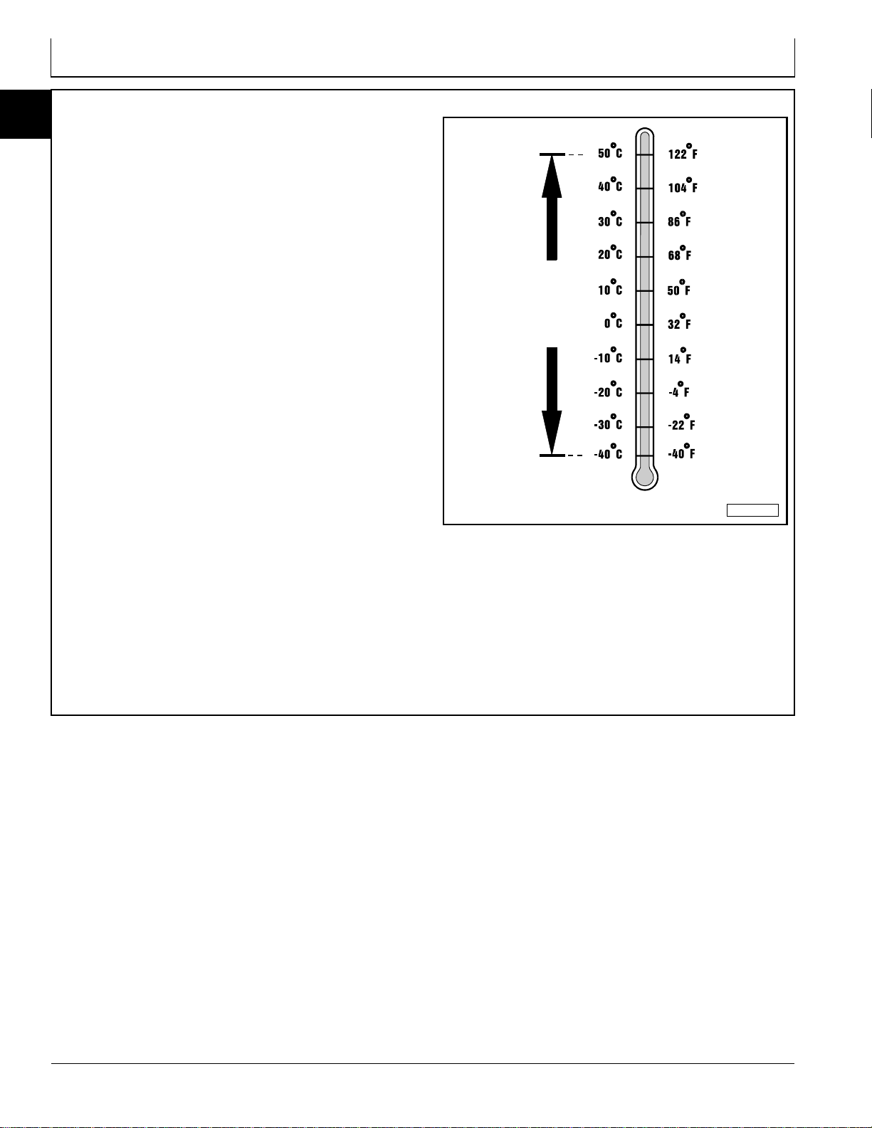
GEAR CASE OIL - EUROPE
20
10
MECHANICAL FRONT WHEEL DRIVE
Use the following oil viscosity based on the air
temperature range. Operating outside of the
recommended oil air temperature range may cause
premature gear case failure.
IMPORTANT: ONLY use a quality oil in this gear
case. DO NOT mix any other oils in
this gear case. DO NOT use BIO–HY–
GARD® in this gear case.
The following John Deere gear case oil is
PREFERRED:
•EXTREME–GARD™—SAE 80W-90.
Other gear case oils may be used if above
recommended John Deere gear case oil is not available,
provided they meet the following specification:
•API Service Classification GL–5.
SAE 80W-90
AIR TEMPERATURE
M58275
John Deere Dealers: You may want to cross-reference
the following publications to recommend the proper oil
for your customers:
•Module DX,GEOIL in JDS–G135;
•Section 530, Lubricants & Hydraulics, of the John
Deere Merchandise Sales Guide.
10-20-10
Page 35

Fuels, Lubricants, and Coolants/Hydraulic/Transmission Oil
GREASE - NORTH AMERICA
(FOR ALL OTHER PRODUCTS AND
COMPONENTS NOT ALREADY COVERED)
Use the following grease based on the air temperature
range. Operating outside of the recommended grease
air temperature range may cause premature failures.
IMPORTANT: ONLY use a quality grease in this
application. DO NOT mix any other
greases in this application. DO NOT
use any BIO–GREASE in this
application.
The following John Deere grease is PREFERRED:
•NON-CLAY HIGH-TEMPERATURE EP GREASE®—
JDM J13E4, NLGI Grade 2.
Other greases may be used if above preferred John
Deere grease is not available, provided they meet the
following specification:
•John Deere Standard JDM J13E4, NLGI Grade 2.
JDM J13E4
NLGI Grade 2
AIR TEMPERATURE
10
20
11
M58275
John Deere Dealers: You may want to cross-reference
the following publications to recommend the proper
grease for your customers:
•Module DX,GREA1 in JDS–G135;
•Section 530, Lubricants & Hydraulics, of the John
Deere Merchandise Sales Guide;
•the Lubrication Sales Manual PI7032.
10-20-11
Page 36

Fuels, Lubricants, and Coolants/Hydraulic/Transmission Oil
10
GREASE - EUROPE
20
12
(FOR ALL OTHER PRODUCTS AND
COMPONENTS NOT ALREADY COVERED)
Use the following grease based on the air temperature
range. Operating outside of the recommended grease
air temperature range may cause premature failures.
IMPORTANT: ONLY use a quality grease in this
application. DO NOT mix any other
greases in this application. DO NOT
use any BIO–GREASE in this
application.
The following John Deere grease is PREFERRED:
•GREASE–GARD™—JDM J13E4, NLGI Grade 2.
Other greases may be used if above preferred John
Deere grease is not available, provided they meet the
following specification:
•John Deere Standard JDM J13E4, NLGI Grade 2.
JDM J13E4
NLGI Grade 2
AIR TEMPERATURE
M58275
John Deere Dealers: You may want to cross-reference
the following publications to recommend the proper
grease for your customers:
•Module DX, GREA1 in JDS–G135;
•Section 530, Lubricants & Hydraulics, of the John
Deere Merchandise Sales Guide.
10-20-12
Page 37

Fuels, Lubricants, and Coolants/Hydraulic/Transmission Oil
ALTERNATIVE LUBRICANTS NORTH AMERICA
Conditions in certain geographical areas outside the
United States and Canada may require different
lubricant recommendations than the ones printed in this
technical manual or the operator's manual. Consult with
your John Deere Dealer, or Sales Branch, to obtain the
alternative lubricant recommendations.
SYNTHETIC LUBRICANTS
Synthetic lubricants may be used in John Deere
equipment if they meet the applicable performance
requirements (industry classification and/or military
specification) as shown in this manual.
The recommended air temperature limits and service or
lubricant change intervals should be maintained as
shown in the operator’s manual, unless otherwise stated
on lubricant label.
IMPORTANT: Use of alternative lubricants could
cause reduced life of the component.
If alternative lubricants are to be used, it is
recommended that the factory fill be thoroughly
removed before switching to any alternative lubricant.
Avoid mixing different brands, grades, or types of oil. Oil
manufacturers blend additives in their oils to meet
certain specifications and performance requirements.
Mixing different oils can interfere with the proper
functioning of these additives and degrade lubricant
performance.
10
20
13
LUBRICANT STORAGE
All machines operate at top efficiency only when clean
lubricants are used. Use clean storage containers to
handle all lubricants. Store them in an area protected
from dust, moisture, and other contamination.
MIXING OF LUBRICANTS
In general, avoid mixing different brands or types of
lubricants. Manufacturers blend additives in their
lubricants to meet certain specifications and
performance requirements.
OIL FILTERS
IMPORTANT: Filtration of oils is critical to proper
lubrication performance. Always
change filters regularly.
The following John Deere oil filters are PREFERRED:
•AUTOMOTIVE AND LIGHT TRUCK ENGINE OIL
FILTERS.
Most John Deere filters contain pressure relief and antidrainback valves for better engine protection.
Store drums on their sides. Make sure all containers are
properly marked as to their contents. Dispose of all old,
used containers and their contents properly.
Mixing different lubricants can interfere with the proper
functioning of these additives and lubricant properties
which will downgrade their intended specified
performance.
Other oil filters may be used if above recommended
John Deere oil filters are not available, provided they
meet the following specification:
•ASTB Tested In Accordance With SAE J806.
John Deere Dealers: You may want to cross-reference
the following publications to recommend the proper oil
filter for your customers:
•Module DX, FILT in JDS–G135;
•Section 540, Lubricants & Hydraulics, of the John
Deere Merchandise Sales Guide;
•Lawn & Grounds Care Tune-Up Guide PI672.
10-20-13
Page 38

Fuels, Lubricants, and Coolants/Hydraulic/Transmission Oil
10
ALTERNATIVE LUBRICANTS -
20
14
EUROPE
Conditions in certain geographical areas outside the
United States and Canada may require different
lubricant recommendations than the ones printed in this
technical manual or the operator's manual. Consult with
your John Deere Dealer, or Sales Branch, to obtain the
alternative lubricant recommendations.
SYNTHETIC LUBRICANTS
Synthetic lubricants may be used in John Deere
equipment if they meet the applicable performance
requirements (industry classification and/or military
specification) as shown in this manual.
The recommended air temperature limits and service or
lubricant change intervals should be maintained as
shown in the operator’s manual, unless otherwise stated
on lubricant label.
IMPORTANT: Use of alternative lubricants could
cause reduced life of the component.
If alternative lubricants are to be used, it is
recommended that the factory fill be thoroughly
removed before switching to any alternative lubricant.
Avoid mixing different brands, grades, or types of oil. Oil
manufacturers blend additives in their oils to meet
certain specifications and performance requirements.
Mixing different oils can interfere with the proper
functioning of these additives and degrade lubricant
performance.
LUBRICANT STORAGE
All machines operate at top efficiency only when clean
lubricants are used. Use clean storage containers to
handle all lubricants. Store them in an area protected
from dust, moisture, and other contamination.
MIXING OF LUBRICANTS
In general, avoid mixing different brands or types of
lubricants. Manufacturers blend additives in their
lubricants to meet certain specifications and
performance requirements.
OIL FILTERS
IMPORTANT: Filtration of oils is critical to proper
lubrication performance. Always
change filters regularly.
The following John Deere oil filters are PREFERRED:
•AUTOMOTIVE AND LIGHT TRUCK ENGINE OIL
FILTERS.
Most John Deere filters contain pressure relief and antidrainback valves for better engine protection.
Store drums on their sides. Make sure all containers are
properly marked as to their contents. Dispose of all old,
used containers and their contents properly.
Mixing different lubricants can interfere with the proper
functioning of these additives and lubricant properties
which will downgrade their intended specified
performance.
Other oil filters may be used if above recommended
John Deere oil filters are not available, provided they
meet the following specification:
•ASTB Tested In Accordance With SAE J806.
John Deere Dealers: You may want to cross-reference
the following publications to recommend the proper oil
filter for your customers:
•Module DX, FILT in JDS–G135;
•Section 540, Lubricants & Hydraulics, of the John
Deere Merchandise Sales Guide;
•Lawn & Grounds Care Tune-Up Guide PI672.
10-20-14
Page 39

Fuels, Lubricants, and Coolants/Hydraulic/Transmission Oil
DIESEL ENGINE COOLANT NORTH AMERICA
The engine cooling system when filled with a proper
dilution mixture of anti-freeze and deionized or distilled
water provides year-round protection against corrosion,
cylinder or liner pitting, and winter freeze protection
down to –37°C (–34°F).
The following John Deere coolant is PREFERRED:
•PRE-DILUTED DIESEL ENGINE ANTI-FREEZE/
SUMMER COOLANT™ (TY16036).
This coolant satisfies specifications for “Automobile and
Light Duty Engine Service” and is safe for use in John
Deere Lawn and Grounds Care/Golf and Turf Division
equipment, including aluminum block gasoline engines
and cooling systems.
The above preferred pre-diluted anti-freeze provides:
•adequate heat transfer
•corrosion-resistant chemicals for the cooling
system
•compatibility with cooling system hose and seal
material
•protection during extreme cold and extreme hot
weather operations
•chemically pure water for better service life
•compliance with ASTM D4656 (JDM H24C2)
specifications
If above preferred pre-diluted coolant is not available,
the following John Deere concentrate is
recommended:
•DIESEL ENGINE ANTI-FREEZE/SUMMER
COOLANT CONCENTRATE™ (TY16034).
If either of above recommended engine coolants are
available use any Automobile and Light Duty Engine
Service ethylene glycol base coolant
following specification:
•ASTM D3306 (JDM H24C1).
, meeting the
IMPORTANT: To prevent engine damage, DO NOT
use pure anti-freeze or less than a
50% anti-freeze mixture in the cooling
system. DO NOT mix or add any
additives/conditioners to the cooling
system in Lawn and Grounds Care/
Golf and Turf Division equipment.
Water used to dilute engine coolant
concentrate must be of high quality—
clean, clear, potable water (low in
chloride and hardness–Table 1) is
generally acceptable. DO NOT use
salt water . Deionized or distilled water
is ideal to use. Coolant that is not
mixed to these specified levels and
water purity can cause excessive
scale, sludge deposits, and increased
corrosion potential.
Table 1: Water Quality
Property Requirements
Total Solids, Maximum 340 ppm (20 grns/gal)
Total Hardness, Max. 170 ppm (10 grns/gal)
Chloride (as Cl), Max. 40 ppm (2.5 grns/gal)
Sulfate (as SO
Mix 50 percent anti-freeze concentrate with 50 percent
distilled or deionized water. This mixture and the prediluted mixture (TY16036) will protect the cooling
system down to -37°C(-34°F) and up to 108°C (226°F).
Certain geographical areas may require lower air
temperature protection. See the label on your antifreeze container or consult your John Deere dealer to
obtain the latest information and recommendations.
), Max. 100 ppm (5.8 grns/gal)
4
10
20
15
Read container label completely before using and follow
instructions as stated.
DIESEL ENGINE COOLANT DRAIN
INTERVAL - NORTH AMERICA
When using John Deere Pre-Diluted (TY16036)
Automobile and Light Duty Engine Service coolants,
drain and flush the cooling system and refill with fresh
coolant mixture every 36 months or 3,000 hours of
operation, whichever comes first.
10-20-15
When using John Deere Concentrate (TY16034)
Automobile and Light Duty Engine Service coolants,
drain and flush the cooling system and refill with fresh
coolant mixture every 24 months or 2,000 hours of
operation, whichever comes first.
If above John Deere Automobile and Light Duty Engine
Service coolants are not being used; drain, flush, and
refill the cooling system according to instructions found
on product container or in equipment operator’s manual
or technical manual.
Page 40

Fuels, Lubricants, and Coolants/Hydraulic/Transmission Oil
10
DIESEL ENGINE COOLANT - EUROPE
20
16
The engine cooling system when filled with a proper
dilution mixture of anti-freeze and deionized or distilled
water provides year-round protection against corrosion,
cylinder liner pitting, and winter freeze protection down
to –37°C (–34°F).
The following John Deere coolant is PREFERRED:
•COOL–GARD COOLANT CONCENTRATE™.
If above preferred coolant is not available, use any
Automobile and Light Duty Engine Service ethylene
glycol base coolant, meeting the following
specification:
•ASTM D3306 (JDM H24C1).
Read container label completely before using and follow
instructions as stated.
IMPORTANT: To prevent engine damage, DO NOT
use pure anti-freeze or less than a
50% anti-freeze mixture in the cooling
system. DO NOT mix or add any
additives/conditioners to the cooling
system in Lawn and Grounds Care/
Golf and Turf Division equipment.
Water used to dilute engine coolant
concentrate must be of high quality—
clean, clear, potable water (low in
chloride and hardness–Table 1) is
generally acceptable. DO NOT use
salt water. Deionized or distilled water
is best to use. Coolant that is not
mixed to these specified levels and
water purity can cause excessive
scale, sludge deposits, and increased
corrosion potential.
Table 1: Water Quality
Property Requirements
Total Solids, Maximum 340 ppm (20 grns/gal)
Total Hardness, Max. 170 ppm (10 grns/gal)
Chloride (as Cl), Max. 40 ppm (2.5 grns/gal)
Sulfate (as SO
), Max. 100 ppm (5.8 grns/gal)
4
DIESEL ENGINE COOLANT DRAIN
INTERVAL - NORTH AMERICA
When using John Deere Pre-Diluted (TY16036)
Automobile and Light Duty Engine Service coolants,
drain and flush the cooling system and refill with fresh
coolant mixture every 36 months or 3,000 hours of
operation, whichever comes first.
Mix 50 percent anti-freeze concentrate with 50 percent
distilled or deionized water. This mixture will protect the
cooling system down to -37°C(-34°F) and up to 108°C
(226°F).
Certain geographical areas may require lower air
temperature protection. See the label on your antifreeze container or consult your John Deere dealer to
obtain the latest information and recommendations.
When using John Deere Concentrate (TY16034)
Automobile and Light Duty Engine Service coolants,
drain and flush the cooling system and refill with fresh
coolant mixture every 24 months or 2,000 hours of
operation, whichever comes first.
If above John Deere Automobile and Light Duty Engine
Service coolants are not being used; drain, flush, and
refill the cooling system according to instructions found
on product container or in equipment operator’s manual
or technical manual.
10-20-16
Page 41

PRODUCT SERIAL NUMBER
Group 25
Serial Number Locations
The tractor’s 13-digit product serial number is located
below rear PTO on transmission case.
Product Serial Number
ENGINE SERIAL NUMBER
The tractor’s engine serial number (A) is located on
valve cover.
Engine Serial Number
10
25
1
M39695 -UN-09SEP88
MX,HU,1025,1 -19-16OCT91
M39696 -UN-09SEP88
MX,HU,1025,2 -19-16OCT91
TRANSAXLE SERIAL NUMBER
The transaxle serial number plate is located on flat
surface (A) below left-hand rockshaft lift arm.
Transaxle Serial Number
MOWER DECK SERIAL NUMBER
The mower deck serial number plate is located at
various points on the different mower decks available for
these tractors.
Mower Deck Serial Number
M48511 -UN-05APR90
MX,HU,1025,3 -19-16OCT91
MX,HU,1025,4 -19-16OCT91
TM1360 (16OCT91) 10-25-1 55, 56 Series Tractors
010395
M35734 -UN-27NOV89
Page 42

10
25
2
Serial Number Locations/Mower Deck Serial Number
TM1360 (16OCT91) 10-25-2 55, 56 Series Tractors
010395
Page 43

Section 20
Page
Group 05—Yanmar Diesel Engine Repair
John Deere Series 220 Diesel Engines . . . .20-05-1
Group 10—Remove and Install Oil Cooler
Remove and Install Oil Cooler . . . . . . . . . . .20-10-1
Group 15—Remove and Install Radiator
Service Equipment and Tools. . . . . . . . . . . .20-15-1
Specifications. . . . . . . . . . . . . . . . . . . . . . . .20-15-1
Remove and Install Radiator . . . . . . . . . . . .20-15-2
Group 20—Remove and Install Diesel Engine
Remove and Install Diesel Engine. . . . . . . .20-20-1
Diesel Engine Repair
20
Contents
20-1
Page 44

20
Contents
TM1360 (16OCT91) 20-2 55, 56 Series Tractors
010395
Page 45

JOHN DEERE/YANMAR DIESEL ENGINE
REPAIR—JOHN DEERE SERIES 220
DIESEL ENGINES
Group 05
Yanmar Diesel Engine Repair
For complete repair information, the COMPONENT
TECHNICAL MANUAL (CTM) is also required, use
JOHN DEERE SERIES 220 DIESEL ENGINES—CTM3
(10AUG93 or later) in conjunction with this machine
manual.
20
05
1
20-05-1
Page 46

20
05
2
Diesel Engine Repair—CTM3
TM1360 (16OCT91) 20-05-2 55, 56 Series Tractors
010395
Page 47

REMOVE AND INSTALL OIL COOLER
NOTE: Late model 755/756 Tractor shown. See
Remove and Install Radiator in Group 15 of this
section for steps required to reach disassembly
point shown. Have a clean oil pan, several shop
cloths, and two oil caps and plugs ready to
catch, trap, and/or clean-up hydraulic oil.
1. Remove two cap screws (A).
2. Disconnect oil cooler lines (B).
3. Lift cooler from base clips (C), one on each side.
4. Drain oil cooler and remove to bench.
5. Remove and discard O-rings.
6. Install new O-rings.
Group 10
Remove and Install Oil Cooler
A
20
10
1
7. Set oil cooler in base clips (C), one on each side.
IMPORTANT: Do not flex oil cooler lines.
Hydrostatic line fittings must align
with oil cooler fittings before lines are
installed onto oil cooler.
8. Loosen clamp that retains hydraulic lines to the
frame.
9. Move hydraulic line’s until hydraulic line and oil cooler
line fitting’s align.
10. Connect oil cooler lines (B) and tighten clamp. If at
this time hydraulic oil cooler line’s do not align, bend
slightly until they do align.
11. Install and tighten two cap screws (A).
12. See Remove and Install Radiator in this section for
final assembly steps.
C
B
M42294
20-10-1
Page 48

20
10
2
Remove and Install Oil Cooler/Remove and Install Oil Cooler
TM1360 (16OCT91) 20-10-2 55, 56 Series Tractors
010395
Page 49

Group 15
Remove and Install Radiator
SERVICE EQUIPMENT AND TOOLS
NOTE: Order tools from the U.S. SERVICE-GARD™ Catalog or from the European Microfiche Tool Catalog (MTC).
Some tools may be available from a local supplier.
Name Use
Overhead 1/2 Ton Hoist Pull Engine
SPECIFICAT IONS
Item Measurement Specification
Fan Blade Radiator Clearance 12mm (1/2 in.)
Engine Side Panel Mounting Tabs Ce nter D istance 655—508 mm (20 in.)
755/756—562 mm (22.1 in.)
855/856/955—567 mm (22.3 in.)
20
15
1
20-15-1
Page 50

Remove and Install Radiator/Remove and Install Radiator
REMOVE AND INSTALL RADIATOR
NOTE: On 955 Tractors and 855/856 Tractors (S/N
615001—999,999 and 1990 model S/N
10,001— ) the fuel tank and battery locations
have been switched. Early model tractor used for
illustrations.
20
1. Remove grille, side shields and hood.
15
2
2. Drain radiator.
3. Remove three hoses (A) and oil cooler (B), see
REMOVE AND INSTALL OIL COOLER in Group 10
earlier in this section.
4. Disconnect return fuel line (C) and pump fuel line (D)
from engine. Pull lines forward from radiator support.
5. Disconnect sender harness (E) leads form fuel tank
sender and pull rearward from radiator support.
6. Disconnect radiator/hood support (F) from upper
radiator bracket (G).
7. Remove radiator/hood support (F) lower frame bolts
from both sides.
8. Have a person pull forward on fuel tank while you pull
up and forward on radiator to clear frame locater pins
and fan.
9. Distance (A) between fan blade and inner face of
shroud must be at least 12 mm (1/2 in.).
10. If less than 12 mm (1/2 in.), make certain two shims
have been inserted under each front engine mount (655).
M70400 -UN-21MAR90
A—Radiator and Air Intake Hoses
B—Oil Cooler
C—Return Fuel Line
D—Pump Fuel Line
E—Fuel Sender Harness
F—Radiator/Hood Support
G—Upper Radiator Bracket
MX,HU,2015,1D -19-16OCT91
MX,HU,2015,2 -19-16OCT91
TM1360 (16OCT91) 20-15-2 55, 56 Series Tractors
010395
M43760 -UN-31AUG88
Page 51

Remove and Install Radiator/Remove and Install Radiator
11. If shims are in place, reposition radiator forward to
obtain at least 12 mm (1/2 in.) clearance. Tighten
mounting bolts (A).
12. Center distance between engine side panel mounting
tabs (B and C) must be:
508 mm (20 in.) on 655
562 mm (22.1 in.) on 755/756
567 mm (22.3 in.) on 855/856/955
20
15
3
M43761 -UN-31AUG88
MX,HU,2015,3 -19-16OCT91
TM1360 (16OCT91) 20-15-3 55, 56 Series Tractors
010395
Page 52

20
15
4
Remove and Install Radiator/Remove and Install Radiator
TM1360 (16OCT91) 20-15-4 55, 56 Series Tractors
010395
Page 53

REMOVE AND INSTALL DIESEL ENGINE
NOTE: Early model tractor used for illustrations. On 955
Tractors and 855 Tractors (S/N 615001—999,999
and 1990 model S/N 10,001— ) the fuel tank
and battery locations have been switched.
Group 20
Remove and Install Diesel Engine
1. Remove grille, side shields, hood, oil cooler, fuel tank
and radiator.
2. Remove items (A — H), lay firewall panel on top of
dash so you don’t have to disconnect the fuse block.
A—Battery
B—Pedestal Side Panels
C—Starting Aid Module With Base
D—Firewall Panel
E—Battery Tray With Cables
F—Muffler Heat Shield
G—Exhaust Pipe
H—Muffler
3. Install lifting eye (A) in upright position.
IMPORTANT: Install plug and cap to keep dirt out of
fuel system.
20
20
1
M70680 -UN-21MAR90
MX,HU,2020,1 -19-16OCT91
4. Disconnect items (B through G).
A—Lifting Eye
B—Fuel Line
C—Throttle Cable Clamps
D—Fuel Pump Connector
E—Oil Pressure Sending Unit
F—Fuel Shut-Off Connector
G—Glow Plug (655/755/756) or Air Heater
(855/856/955) Terminal
MX,HU,2020,2 -19-16OCT91
TM1360 (16OCT91) 20-20-1 55, 56 Series Tractors
010395
M43688 -UN-08SEP88
Page 54

5. Disconnect items (A - F).
A—Drive Shaft Isolator
B—Starter Connections
C—Alternator Connections
D—Tachometer Cable
E—Temperature Sender
F—Harness Clamp
20
20
2
Remove and Install Diesel Engine/Remove and Install Diesel Engine
6. Remove four engine mounting bolts (A).
7. Remove engine from tractor frame. Keep shims (B), if
equipped, for engine installation (655 Tractors Only).
INSTALLATION:
8. Reverse removal procedures noting the following
items:
—Reinstall same number of shims (B) as removed on
655 Tractor.
—See Section 220, Group 10 for proper adjustment of
throttle cable and fuel shut-off solenoid.
M43689 -UN-08SEP88
MX,HU,2020,3 -19-16OCT91
MX,HU,2020,4 -19-16OCT91
TM1360 (16OCT91) 20-20-2 55, 56 Series Tractors
010395
M43690 -UN-31AUG88
Page 55

Page
Group 05—Fuel Transfer Pump
Remove and Install Fuel Transfer Pump . . .30-05-1
Group 10—Fuel Tank
Remove and Install Fuel Tank . . . . . . . . . . .30-10-1
Group 15—Fuel Tank Tube and Sender
Remove and Install Fuel Tank Tube
and Sender . . . . . . . . . . . . . . . . . . . . . . . .30-15-1
Group 20—Air Cleaner
Specifications. . . . . . . . . . . . . . . . . . . . . . . .30-20-1
Remove and Install Air Cleaner . . . . . . . . . .30-20-2
Remove and Install Air Restriction
Indicator. . . . . . . . . . . . . . . . . . . . . . . . . . .30-20-4
Section 30
Fuel and Air Repair
Contents
30
30-1
Page 56

30
Contents
TM1360 (16OCT91) 30-2 55, 56 Series Tractors
010395
Page 57

REMOVE AND INSTALL FUEL TRANSFER
PUMP
1. Lift hood. Remove right-hand engine shield.
2. Disconnect power lead (A).
3. Loosen hose clamps (B). Remove hoses from fuel
pump. Plug hoses to prevent fuel contamination.
4. Remove cap screws (C). Remove fuel pump.
Group 05
Fuel Transfer Pump
5. Install and fasten new fuel pump to bracket. Be sure
end of pump marked “IN” is to the front of tractor.
6. Connect fuel hoses and power lead.
7. Bleed fuel injection system. (Refer to Section 220.)
All 955 Tractors and late model 855 Tractors (S/N
615001—999,999 and 1990 models S/N 10,001— )
use a mechanical fuel pump.
30
05
1
M43633 -UN-31AUG88
MX,HU,3005,1 -19-16OCT91
955 Tractor Shown
MX,HU,3005,2 -19-16OCT91
TM1360 (16OCT91) 30-05-1 55, 56 Series Tractors
010395
M48512 -UN-12MAR90
Page 58

30
05
2
Fuel Transfer Pump/Remove and Install Fuel Transfer Pump
TM1360 (16OCT91) 30-05-2 55, 56 Series Tractors
010395
Page 59

REMOVE AND INSTALL FUEL TANK
NOTE: 755/756 Tractors illustrated only.
1. Remove front grill screen assembly.
2. Remove cap screws (A) on both sides of tractor.
3. Loosen nuts and remove front plate.
Group 10
Fuel Tank
M43526 -UN-31AUG88
MX,HU,3010,1 -19-16OCT91
30
10
1
4. Remove hose (A) and cap screws (B).
5. Disconnect lighting wire connector (C).
6. Remove fuel tank cap, spill cup, and drain hose.
7. Remove hood.
M43527 -UN-31AUG88
MX,HU,3010,2 -19-16OCT91
MX,HU,3010,3 -19-16OCT91
TM1360 (16OCT91) 30-10-1 55, 56 Series Tractors
010395
M43528 -UN-31AUG88
Page 60

Fuel Tank/Remove and Install Fuel Tank
8. Remove and plug or cap fuel lines (A and B).
9. Disconnect wires (C and D).
10. Remove fuel tank.
11. Check fuel tank for cracks, holes or worn spots.
Replace tank if damaged.
IMPORTANT: Replace foam seals or pads whenever
fuel tank is removed and installed.
12. Install fuel tank in reverse order of removal. Make
30
certain all rubber seals and front pads are in proper
10
locations and in good condition.
2
M48002 -UN-31AUG88
A—Supply line
B—Return line
C—Black Wire
D—Black/White Striped Wire
MX,HU,3010,4 -19-16OCT91
TM1360 (16OCT91) 30-10-2 55, 56 Series Tractors
010395
Page 61

REMOVE AND INSTALL FUEL TANK TUBE
AND SENDER
NOTE: 755 Tractor illustrated only.
1. Remove and plug fuel lines (A and B).
2. Disconnect wires (C and D).
3. Remove screws (E).
Group 15
Fuel Tank Tube and Sender
4. Remove tube and sender from tank.
NOTE: See Remove and Install Fuel Tank for Sender
access.
5. Remove filter screen (A). Clean and inspect screen
and hose for damage. Replace as necessary. Keep
length of hose and pickup same as original.
6. Inspect float (B) for cracks or damage. Replace as
necessary.
7. Inspect gasket (C) for deterioration. Replace as
necessary.
A—Supply line
B—Return line
C—Black Wire
D—Black/White Striped Wire
E—Screws
M48003 -UN-31AUG88
30
15
1
MX,HU,3015,1 -19-16OCT91
M43651 -UN-31AUG88
MX,HU,3015,2 -19-16OCT91
8. Install gasket (A) and align holes. Start screws
through gasket.
9. Install tube and sender. Tighten screws securely.
10. Reinstall hoses and wires.
11. Bleed fuel system. See BLEED FUEL INJECTION
SYSTEM in Section 220.
MX,HU,3015,3 -19-16OCT91
TM1360 (16OCT91) 30-15-1 55, 56 Series Tractors
010395
M43652 -UN-31AUG88
Page 62

30
15
2
Fuel Tank Tube and Sender/Remove and Install Fuel Tank Tube and Sender
TM1360 (16OCT91) 30-15-2 55, 56 Series Tractors
010395
Page 63

Air Cleaner
SPECIFICAT IONS
Item Measurement Specification
Primary Air Cleaner Air Restriction 635 mm (25 in.) Vacuum
Secondary Air Cleaner Air Restriction 508 mm (20 in.) Vacuum
Group 20
Air Restriction Indicator Torque FINGER TIGHT ONLY
30
20
1
30-20-1
Page 64

Air Cleaner/Remove and Install Air Cleaner
REMOVE AND INSTALL AIR CLEANER—
655, 755/756 AND EARLY 855/856
TRACTORS
IMPORTANT: DO NOT clean the primary air cleaner
element with water or compressed air .
Replace it only when the air
restriction indicator shows 635 mm
(25 in.) of vacuum or locks into the
red position.
30
20
2
1. STOP engine, set park brake, and open hood.
2. Remove outside wing nut with washer (A) to remove
cover assembly (B).
3. Remove inside wing nut with washer (C) and primary
element (D).
Tapping the filter on a hard surface
Does Not Help to clean it! It may dent
the wire mesh bringing the paper
element in contact with the mesh.
During normal operation the filter will
vibrate and if it’s touching the wire
mesh, a hole will develop in the paper .
B
A
M62774
D
C
IMPORTANT: Ensure the washer is used with the
wing nut, this will ensure that only
filtered air enters the combustion
chamber.
A properly secured air filter can not
be rotated with one hand.
4. Install new element and secure with wing nut and
washer.
5. Install cover and secure with wing nut and washer.
6. Push reset button (A) on air restriction indicator.
Indicator must reset.
7. START engine and allow to run one minute at
maximum speed.
8. STOP engine and check air restriction indicator. If
indicator shows 508 mm (20 in.) or more vacuum,
replace secondary element.
SECONDARY ELEMENT REPLACEMENT
IMPORTANT: DO NOT clean secondary element,
replace it only when air restriction
indicator shows 508 mm (20 in.)
vacuum and new primary element has
been installed. DO NOT remove
secondary element unless both these
conditions are present.
M62775
A
M62776
A
B
9. Remove primary element as described above, but do
not discard primary element.
10. Remove innermost wing nut and washer (A),
remove secondary element (B) and discard.
30-20-2
M62777
Page 65

Air Cleaner/Remove and Install Air Cleaner
11. Install new secondary element and secure with
wing nut and washer.
12. Install primary element and secure with wing nut
and washer.
13. Install cover and secure with wing nut and washer.
14. Push reset button on air restriction indicator.
Indicator must reset.
REMOVE AND INSTALL AIR CLEANER—
LATE 855 AND ALL 955 TRACTORS
IMPORTANT: DO NOT clean the primary air cleaner
element with water or compressed air .
Replace it only when the air
restriction indicator shows 635 mm
(25 in.) of vacuum or locks into the
red position.
Tapping the filter on a hard surface
Does Not Help to clean it! It may dent
the wire mesh bringing the paper
element in contact with the mesh.
During normal operation the filter will
vibrate and if it’s touching the wire
mesh, a hole will develop in the paper .
1. STOP engine, set park brake, and remove grille.
30
20
3
A
M62586
2. Loosen two wing nuts (A) and adjacent intake hose
clamp to rotate air cleaner assembly forward for access.
3. Remove outside wing nut with washer (B) to remove
cover assembly.
4. Remove inside wing nut with washer (C) and primary
element (D).
IMPORTANT: Ensure the washer is used with the
wing nut, this will ensure that only
filtered air enters the combustion
chamber.
A properly secured air filter can not
be rotated with one hand.
5. Install new element and secure with wing nut and
washer.
6. Install cover and secure with wing nut and washer.
7. Push reset button (A) on air restriction indicator.
Indicator must reset.
8. START engine and allow to run one minute at
maximum speed.
9. STOP engine and check air restriction indicator. If
indicator shows 508 mm (20 in.) or more vacuum,
replace secondary element.
B
M62587
D
C
M62588
30-20-3
Page 66

Air Cleaner/Remove and Install Air Cleaner
SECONDARY ELEMENT REPLACEMENT
IMPORTANT: DO NOT clean secondary element,
replace it only when air restriction
indicator shows 508 mm (20 in.)
vacuum and new primary element has
been installed. DO NOT remove
secondary element unless both these
conditions are present.
10. Remove primary element as described above, but
30
do not discard primary element.
20
4
11. Remove innermost wing nut and washer (A),
remove secondary element (B) and discard.
12. Install new secondary element and secure with
wing nut and washer.
13. Install primary element and secure with wing nut
and washer.
14. Install cover and secure with wing nut and washer.
15. Rotate assembly into position, tighten two wing nuts
and hose clamp.
B
A
M62798
16. Push reset button on air restriction indicator.
Indicator must reset. Install grille.
REMOVE AND INSTALL AIR RESTRICTION
INDICATOR
IMPORTANT: A faulty air restriction indicator, that
goes undetected, may cause a dusted
engine. Make sure all air restriction
indicators are in good condition and
the proper air restriction indicator is
installed (DIESEL INDICATOR ON
DIESEL ENGINE) before any tractor
so equipped is released to the
customer. Always test new indicators.
1. Remove the air restriction indicator (A) with your
fingers—DO NOT use a pliers.
2. Carefully clean the inlet area of the indicator without
getting dirt inside.
3. Put the inlet in your mouth and suck until the
indicator locks in the red position.
4. Remove the inlet from your mouth and push the reset
button. The indicator should reset to zero. If the
indicator does not lock in the red or will not reset, check
for air leaks in the filtered portion of the intake system. If
remote mounted, check for leaks in the restriction
indicator hose. Replace if necessary.
A
Air Restriction Indicator may differ
Note:
from depiction
.
M62776
5. Reinstall the indicator finger tight. Overtightening will
crack the housing.
30-20-4
Page 67

Page
Group 05—Alternator Repair Specifications
Service Equipment and Tools. . . . . . . . . . . .40-05-1
Specifications. . . . . . . . . . . . . . . . . . . . . . . .40-05-1
Alternator Repair . . . . . . . . . . . . . . . . . . . . .40-05-1
Group 10—Alternator Installation
Installation Procedures. . . . . . . . . . . . . . . . .40-10-1
Section 40
Alternator Repair
Contents
40
40-1
Page 68

40
Contents
TM1360 (16OCT91) 40-2 55, 56 Series Tractors
010395
Page 69

Group 05
Alternator Repair Specifications
SERVICE EQUIPMENT AND TOOLS
NOTE: Order tools from the U.S. SERVICE-GARD™ Catalog or from the European Microfiche Tool Catalog (MTC).
Some tools may be available from a local supplier.
Name
Volt-Ohm-Amp Meter Check continuity
13-Ton Bearing Puller Set Remove rotor shaft bearing
Soldering Gun (120 Watt Capacity) & Solder
(Only 60-40 Rosin Core)
Sandpaper (No. 00 or 400-Grit Silicon Carbide Paper) Polish Slip Rings
Use
Disconnect/Connect Wire Terminals
SPECIFICAT IONS
Item: Alternator: Specifications:
Minimum Exposed Brush Length Nippon Denso 35 Amp
Nippon Denso 40 Amp
Maximum Exposed New Brush Length Nippon Denso 35 Amp
Nippon Denso 40 Amp
5.5 mm (0.22 in.)
4.5 mm (0.18 in.)
13.0 mm (0.50 in.)
10.5 mm (0.41 in.)
40
05
1
Sheave Nut Torque Nippon Denso 35 Amp
Nippon Denso 40 Amp
Belt Deflection All Engines 10-15 mm (0.400-0.600 in.) at
54 N•m (40 lb-ft.)
69 N•m (51 lb-ft.)
98N (22lb) Force Between Sheaves.
ALTERNATOR REPAIR
For complete repair information, the COMPONENT
TECHNICAL MANUAL (CTM) is also required. Use
(10Aug93 or later) to repair all alternators.
40-05-1
Page 70

40
05
2
Alternator Repair Specifications/Specifications
TM1360 (16OCT91) 40-05-2 55, 56 Series Tractors
010395
Page 71

INSTALLATION PROCEDURES
IMPORTANT: If replacing original alternator with
service alternator be sure to order
correct mounting hardware. These
installation procedures apply to the
following engine serial numbers 655
(sn 025201 and below), 755 (s/n 030103 and below), 855 (s/n -009848
and below), and 955 (s/n -009848 and
below). For all other alternators the
procedures differ slightly. Use
exploded view for reference.
NOTE: For 855’s only. If alternator belt cannot be
removed (because top mounting tab hits muffler
when pushed in) grind away back edge to
provide clearance. This has already been done
on engines s/n CH3033A010453 and above.
Group 10
Alternator Installation
A
B
40
10
1
1. Remove and discard original 8 mm diameter lower
mounting bolt (A).
2. The rear (engine block) side of the lower engine
alternator mounting boss is threaded to access a 10
mm bolt or stud (B).
3. (655 & 755) Install the appropriate length 10 mm
pivot bolt and tighten to 27 N•m (20 lb-ft).
4. (855 & 955) Install stud in lower pivot hole on radiator
side. Slide alternator pivot hole over stud and secure
with nut tightened to 48•m (35 lb-ft).
5. Install belt on alternator pulley.
6. Belt should deflect approximately 10-15 mm (0.400-
0.600 in.) at 98N (22lb) force between sheaves. Check
belt tension between fan and alternator using belt
tension gauge and a straight edge.
7. To adjust belt, loosen adjusting nut, apply pressure to
front alternator housing only (near the belt) until tension
is correct, then tighten nut.
8. Tighten remaining hardware. See Section 10 Group
15 Repair Information for additional torque values.
9. Install red wire to top stud terminal (positive
terminal).
M85128
35-Amp Alternator
A
10. Plug yellow/brown wire connector into connector at
rear of housing (charging system).
11. Install black wire to bottom bolt at rear of housing
(ground terminal).
NOTE: There is no separate voltage regulator. The
regulator was built into original 35-amp
alternator and is built into new 40-amp
alternator.
40-10-1
M85129
B
40-Amp Alternator
Page 72

10
Alternator Installation/Installation
40
2
40-10-2
Page 73

Contents
Page
Section 50
Power Train Repair
Page
Group 05—Hydrostatic Transmission
Service Equipment and Tools. . . . . . . . . . . .50-05-1
Specifications. . . . . . . . . . . . . . . . . . . . . . . .50-05-2
Remove/Install Sheet Metal Panels. . . . . . .50-05-2
Remove Drive Shaft. . . . . . . . . . . . . . . . . . .50-05-3
Install Drive Shaft. . . . . . . . . . . . . . . . . . . . .50-05-4
Remove/Install MFWD Drive Shaft . . . . . . .50-05-4
Remove/Install Charge Pump . . . . . . . . . . .50-05-5
Remove Hydrostatic Transmission. . . . . . . .50-05-6
Cross-Section View
Hydrostatic Transmission . . . . . . . . . . . .50-05-10
Disassemble Transmission . . . . . . . . . . . .50-05-11
Cross-Section View—Center Section . . . .50-05-18
Assemble Transmission. . . . . . . . . . . . . . .50-05-20
Install Transmission . . . . . . . . . . . . . . . . . .50-05-25
Service Procedure . . . . . . . . . . . . . . . . . . .50-05-28
Flush Hydraulic System . . . . . . . . . . . . . . .50-05-28
Bleed Hydraulic System. . . . . . . . . . . . . . .50-05-28
Group 10—Transaxle
Service Equipment and Tools. . . . . . . . . . . .50-10-1
Fabricated Tools. . . . . . . . . . . . . . . . . . . . . .50-10-1
Other Materials. . . . . . . . . . . . . . . . . . . . . . .50-10-2
Specifications. . . . . . . . . . . . . . . . . . . . . . . .50-10-3
Replace Seals . . . . . . . . . . . . . . . . . . . . . . .50-10-5
Removal Preparations . . . . . . . . . . . . . . . . .50-10-5
Disconnect Linkage . . . . . . . . . . . . . . . . . . .50-10-6
Remove Transaxle. . . . . . . . . . . . . . . . . . . .50-10-8
Remove Final Drive Axles . . . . . . . . . . . . . .50-10-9
Cross-Section View . . . . . . . . . . . . . . . . . .50-10-12
Repair Oil Supply System . . . . . . . . . . . . .50-10-14
Repair PTO Inertia Brake. . . . . . . . . . . . . .50-10-15
Repair PTO Valves. . . . . . . . . . . . . . . . . . .50-10-17
Repair Rear PTO Shaft Assembly . . . . . . .50-10-19
Repair Differential Assembly . . . . . . . . . . .50-10-20
Repair MFWD Gear Case Assembly . . . . .50-10-23
Remove Front Gear Case Cover . . . . . . . .50-10-26
Remove Gear Shaft Assemblies . . . . . . . .50-10-27
Repair PTO Shift Fork Assembly. . . . . . . .50-10-29
Repair PTO Reduction Shaft Assembly. . .50-10-32
Repair Main PTO Shaft Assembly . . . . . . .50-10-33
Repair Mid PTO Shaft Assembly . . . . . . . .50-10-34
Repair Reduction Shaft Assembly . . . . . . .50-10-35
Repair Range Shift Fork Assembly . . . . . .50-10-42
Repair PTO Clutch Assembly . . . . . . . . . .50-10-43
Cross-Section View—PTO Clutch . . . . . . .50-10-47
Assemble PTO Clutch . . . . . . . . . . . . . . . .50-10-47
Install PTO Clutch Assemblies . . . . . . . . . 50-10-50
Repair Differential Drive Shaft Assembly . 50-10-50
Install Differential Drive Shaft Assembly. . 50-10-51
Install Mid PTO Shaft Assembly . . . . . . . . 50-10-52
Install Hi/Lo Reduction Shaft Assembly . . 50-10-52
Install Mid PTO Transfer Gear
Assembly . . . . . . . . . . . . . . . . . . . . . . . . 50-10-52
Install Front Case Cover Assembly. . . . . . 50-10-53
Install MFWD Gear Case Assembly . . . . . 50-10-55
Adjust Backlash—Differential Assembly. . 50-10-56
Install Rear PTO Shaft Assembly . . . . . . . 50-10-59
Install Rear Case Cover Assembly. . . . . . 50-10-59
Install PTO Valve Assemblies. . . . . . . . . . 50-10-60
Install PTO Inertia Brake Assembly . . . . . 50-10-61
Install Oil Supply System . . . . . . . . . . . . . 50-10-62
Install Final Drive Axle Assemblies. . . . . . 50-10-63
Install Transaxle . . . . . . . . . . . . . . . . . . . . 50-10-65
Install Hydrostatic Transmission. . . . . . . . 50-10-65
Install Linkage. . . . . . . . . . . . . . . . . . . . . . 50-10-67
Install ROPS . . . . . . . . . . . . . . . . . . . . . . . 50-10-68
Install Rear Wheels. . . . . . . . . . . . . . . . . . 50-10-69
Install Rockshaft Housing Assembly. . . . . 50-10-69
Connect Flow Divider and Selective
Control Valves . . . . . . . . . . . . . . . . . . . . 50-10-69
Fill Hydraulic System Reservoir . . . . . . . . 50-10-69
Bleed Hydraulic System . . . . . . . . . . . . . . 50-10-70
Adjust Control Linkages . . . . . . . . . . . . . . 50-10-70
Group 15—Final Drives
Service Equipment And Tools. . . . . . . . . . . 50-15-1
Other Material. . . . . . . . . . . . . . . . . . . . . . . 50-15-1
Specifications . . . . . . . . . . . . . . . . . . . . . . . 50-15-2
Remove Final Drives. . . . . . . . . . . . . . . . . . 50-15-2
Planetary Carrier End Play Specification . . 50-15-4
Disassemble Final Drives . . . . . . . . . . . . . . 50-15-5
Repair Planetary Gear Assembly . . . . . . . . 50-15-6
Remove Brake Camshaft Assembly. . . . . 50-15-10
Remove Axle Shafts . . . . . . . . . . . . . . . . . 50-15-10
Remove Oil Seal Wear Sleeve and
Cover . . . . . . . . . . . . . . . . . . . . . . . . . . . 50-15-11
Repair Axle Housing Assembly. . . . . . . . . 50-15-11
Assemble Axle Housing Assembly . . . . . . 50-15-13
Install Brake Camshaft Assembly . . . . . . . 50-15-14
Install Planetary Gear Assembly. . . . . . . . 50-15-14
Continued on next page
50
50-1
Page 74

Group 15—Final Drives Continued
Install Final Drives . . . . . . . . . . . . . . . . . . 50-15-16
Install ROPS and Final Assembly. . . . . . . 50-15-18
Bleed Hydraulic System . . . . . . . . . . . . . . 50-15-19
Adjust Control Linkages . . . . . . . . . . . . . . 50-15-19
Group 20—Mechanical Front Wheel Drive
(MFWD)
Specifications . . . . . . . . . . . . . . . . . . . . . . . 50-20-1
Other Material. . . . . . . . . . . . . . . . . . . . . . . 50-20-1
Service Equipment and Tools. . . . . . . . . . . 50-20-2
Remove MFWD Axle . . . . . . . . . . . . . . . . . 50-20-2
Disassemble Final Drive Case . . . . . . . . . . 50-20-4
Disassemble Spindle Gear Case . . . . . . . 50-20-10
Cross-Section View . . . . . . . . . . . . . . . . . 50-20-16
Assemble Spindle Gear Case . . . . . . . . . 50-20-18
Disassemble Differential Input Housing . . 50-20-23
Disassemble Differential. . . . . . . . . . . . . . 50-20-24
Assemble Differential . . . . . . . . . . . . . . . . 50-20-26
Assemble Axle Housings . . . . . . . . . . . . . 50-20-30
50
Adjust Front Axle End-Play. . . . . . . . . . . . 50-20-32
Adjust Front Axle Toe-In . . . . . . . . . . . . . . 50-20-32
Contents
Page
Group 25—Power Train Gears and Shafts
Exploded View . . . . . . . . . . . . . . . . . . . . . . 50-25-2
Group 30—Speed Control Linkage
Specifications . . . . . . . . . . . . . . . . . . . . . . . 50-30-1
Remove Speed Control Linkage. . . . . . . . . 50-30-1
3-Dimensional View . . . . . . . . . . . . . . . . . . 50-30-6
Install Speed Control Linkage. . . . . . . . . . . 50-30-7
50-2
Page 75

Group 05
Hydrostatic Transmission
SERVICE EQUIPMENT AND TOOLS
NOTE: Order tools from the U.S. SERVICE-GARD™ or from the European Microfiche Tool Catalog (MTC).
Some tools may be available from a local supplier.
Name
Bushing, Bearing, and Seal Driver Set To service bearings and seals.
2-Jaw Slide Hammer Puller To remove bearings.
Knife-Edge Puller To remove bearings.
Hydraulic Press To service bearings.
Snap Ring Pliers Set To remove snap rings.
Overhead Hoist To remove hydrostatic transmission.
Work Bench Fixture To disassemble hydrostatic transmission.
#4—40 x 1 UNC-2B Cap Screw To remove motor bearings retaining pin (Early Models).
#8—32 x 1 UNC-2B Cap Screw To remove motor bearings retaining pin (Late Models).
Use
50
05
1
50-05-1
Page 76

Hydrostatic Transmission/Remove/Install Sheet Metal Panels
SPECIFICATIONS
Item Measurement Specification
Charge Pump Cap Screw Torque 37—50 N•m (27—37 lb-ft)
Charge Inlet Fitting Torque 95—230 N•m (70—170 lb-ft)
Drive Shaft-to-Engine Cap Screw Torque 49 N•m (35 lb-ft)
Drive Shaft-to-Hydro Cap Screw Torque 60 N•m (45 lb-ft)
Neutral Return Lever Bushing Inside Diameter 19.088 ± 0.025 mm
(0.7515 ± 0.001 in)
Drive Shaft Coupler to Hydro Input
Torque 60 N•m (45 lb-ft)
Shaft
Swash Plate End Caps Cap Screw Torque 8—9 N•m (72—84 lb-in)
50
05
Transmission Center
2
Cap Screw Torque 44—55 N•m (33—41 lb-ft)
Section-to-Housing
Gear-to-Output Shaft Cap Screw Torque (Early Models)
Castle Nut Torque (Late Models)
54 N•m (40 lb-ft)
109 N•m (80 lb-ft)
Transmission Attaching Cap Screw Torque 142 N•m (105 lb-ft)
Neutral Return Lever Spring Adjusted Coil Length 133 mm (5.25 in)
Plugs:
3/4-16 SAE O-ring Torque 45—95 N•m (33—70 lb-ft)
1/4-20 SAE O-ring Torque 4—7 N•m (36—60 lb-in)
REMOVE AND INSTALL SHEET METAL PANELS
1. Park tractor safely. Lock park brake, remove key.
2. Turn depth control lever (A) clockwise until it stops.
3. Remove four cap screws. To remove panel (B), lift up
on right rear corner of panel first, then lift left side to
clear head of depth control bolt, and move panel out
from the right side of the tractor.
50-05-2
B
A
M43634
Page 77

Hydrostatic Transmission/Remove Drive Shaft
NOTE: 755/756, 855/856, and 955 tractors have two
additional side cap screws under each fender.
4. Remove panel (A).
NOTE: Panel need not be removed for driveshaft and
charge pump repair.
5. Install in reverse order. Be sure depth control lever
aligns with bolt head.
M43638 -UN-31AUG88
655 Shown
MX,HU,5005,7 -19-16OCT91
REMOVE DRIVE SHAFT
1. Loosen two bolts (A) of drive shaft coupler.
2. Remove six cap screws (A).
3. Push driveshaft (B) back to remove isolator (C).
4. Remove driveshaft.
50
05
3
M43635 -UN-31AUG88
MX,HU,5005,8 -19-16OCT91
MX,HU,5005,9 -19-16OCT91
TM1360 (16OCT91) 50-05-3 55, 56 Series Tractors
010395
M43512 -UN-31AUG88
Page 78

Hydrostatic Transmission/Remove/Install MFWD Drive Shaft
INSTALL DRIVE SHAFT
1. Put drive shaft (B) on transmission.
2. Install isolator (C). Be sure raised portion of
unthreaded holes are toward engine.
3. Fasten isolator to engine with three longer cap screws
and fasten drive shaft to isolator with three shorter cap
screws (A). Tighten cap screws to 49 N·m (36 lb-ft).
4. Tighten two bolts (A) of drive shaft coupler to 60 N·m
(45 lb-ft).
M43512 -UN-31AUG88
MX,HU,5005,10 -19-16OCT91
50
05
4
REMOVE AND INSTALL MFWD DRIVE SHAFT
1. Loosen clamps. Slide front and rear covers away from
universal joints.
M43511 -UN-31AUG88
MX,HU,5005,11 -19-16OCT91
M37522 -UN-06SEP88
MX,HU,5005,11A -19-16OCT91
TM1360 (16OCT91) 50-05-4 55, 56 Series Tractors
010395
Page 79

Hydrostatic Transmission/Remove/Install Charge Pump
2. Drive pin out of front universal joint to remove shaft.
3. To install, align pin holes of drive shaft front U-joint
and MFWD input shaft as you slide the shaft into
position.
4. Fasten with spring pin removed earlier.
5. Fasten front cover in place with band clamps.
6. Fasten rear U-joint of drive shaft to transaxle output
shaft.
7. Fasten rear cover in place with band clamps.
M37523 -UN-06SEP88
MX,HU,5005,12 -19-16OCT91
REMOVE AND INSTALL CHARGE PUMP
NOTE: Orientation of charge pump: Flat on charge pump
housing must be on right-hand side. If turned
180˚, pump will not function.
1. Remove two cap screws (A) to remove charge pump.
50
05
5
M43636 -UN-31AUG88
MX,HU,5005,13 -19-16OCT91
TM1360 (16OCT91) 50-05-5 55, 56 Series Tractors
010395
Page 80

Hydrostatic Transmission/Remove Hydrostatic Transmission
2. Remove pin (A). Inspect pin for damage or wear.
Replace if necessary.
3. Inspect machined surface of transmission for severe
scoring. If scoring is noted, replace transmission.
4. Clean and dry all parts. Machined surface of
transmission must be clean.
5. Apply clean transmission oil on all internal parts.
6. Install pin (A). Apply petroleum jelly to pin and shaft to
hold pin in place during installation of charge pump.
7. Be sure O-ring is in place on pump.
8. Torque cap screws (Step 1) to specification.
TORQUE SPECIFICATION
Charge Pump Cap Screws . . . . . . . . . . . . . . 37-50 N·m (27-37 lb-ft)
50
05
6
REMOVE HYDROSTATIC TRANSMISSION
1. Drain transaxle. Oil capacity is approximately 17 L
(4.5 gal).
2. Remove the following:
M43637 -UN-19JAN90
MX,HU,5005,14 -19-16OCT91
• Drawbar
• Sheet Metal Panels (see procedures in this group)
• Transmission Drive Shaft (see procedures in this
group)
• MFWD Drive Shaft (see procedures in this group).
MX,HU,5005,16 -19-16OCT91
TM1360 (16OCT91) 50-05-6 55, 56 Series Tractors
010395
M43506 -UN-31AUG88
Page 81

Hydrostatic Transmission/Remove Hydrostatic Transmission
3. Disconnect spring (A) from lever (B).
4. Remove bolt (C) to disconnect linkage from
transmission (D).
A—Spring
B—Transmission Neutral Return Lever
C—Bolt
D—Transmission
IMPORTANT: Close all openings with caps and plugs
to keep dirt out of the hydraulic
system.
5. Disconnect fitting (A). Loosen clamp on other end and
turn tube (B) to permit transmission removal.
6. Disconnect line (C).
M43639 -UN-31AUG88
MX,HU,5005,17 -19-16OCT91
7. Disconnect lines (D).
8. Disconnect wiring (E).
A—Fitting
B—Suction Line
C—Steering Line
D—Oil Cooler Lines (2)
E—Neutral Start Wire
50
05
7
M43640 -UN-31AUG88
MX,HU,5005,18 -19-16OCT91
TM1360 (16OCT91) 50-05-7 55, 56 Series Tractors
010395
Page 82

Hydrostatic Transmission/Remove Hydrostatic Transmission
9. Fasten a lifting eye to the transmission and hold
transmission with an overhead hoist.
10. Remove two cap screws (A).
11. Move transmission forward so that output gear clears
transaxle, then lower transmission to remove it.
M43641 -UN-31AUG88M43642 -UN-31AUG88
50
05
8
12. Remove cap screw and speed control lever (A).
13. Remove cap screw and neutral return lever (B).
14. Remove O-rings (C).
15. Remove three fittings (D).
A—Cap Screw/Speed Control Lever
B—Cap Screw/Neutral Return Lever
C—O-ring
D—Fittings
16. If neutral start switch is being replaced, be sure to
install spacer (A) between switch and speed control
lever.
MX,HU,5005,19 -19-16OCT91
M43678 -UN-31AUG88
MX,HU,5005,20 -19-16OCT91
MX,HU,5005,21 -19-16OCT91
TM1360 (16OCT91) 50-05-8 55, 56 Series Tractors
010395
M43680 -UN-31AUG88
Page 83

Hydrostatic Transmission/Remove Hydrostatic Transmission
17. Inspect neutral return lever rollers (B). Replace them
if they DO NOT turn freely.
18. Inspect bronze bushing in neutral return lever (D) for
excessive wear on the inside diameter. If bushing is
being replaced, be sure to align hole in bushing with
grease fitting hole in lever. Ream bushing to 19.088 ±
0.025 mm (0.7515 ± 0.001 in.) diameter.
A—Lock nut
B—Roller (2 used)
C—Washer (2 used)
D—Neutral Return Lever
E—Thin Washer
F—Short Cap Screw
G—Long Cap Screw
H—Eccentric Pivot
I—Seal Cover (2 used)
J—Felt Seal (2 used)
M43679 -UN-31AUG88
MX,HU,5005,22 -19-16OCT91
50
05
9
TM1360 (16OCT91) 50-05-9 55, 56 Series Tractors
010395
Page 84

Hydrostatic Transmission/Cross-Section View Hydrostatic Transmission
CROSS-SECTION VIEW—HYDROSTATIC TRANSMISSION
50
05
10
13
15
12
14
16
17
18
19
20
21
22
24
25
23
26
1
2
11
10
1—Needle Bearing
2—Seal
3—Filter
4—Pin (2 used)
5—Needle Bearing (2 Used)
6—Motor Valve Plate
7—Motor Cylinder Block
Assembly With Fixed
Thrust Plate
9
8
8—Drain Plug
9—Bearing Retaining Pin
10—Ball Bearing (2 Used)
11—Late Model Motor Shaft
(Early Models Are Not
Threaded)
12—Collar
13—Pump Shaft
7
27
14—Seal Guide
15—Snap Ring
16—O-Ring
17—Ball Bearing
18—Thrust Plate
19—Variable Swash Plate
20—Pump Cylinder Block
Assembly (2 Used)
6
5
4
21—Pin (2 Used)
22—Pump Valve Plate
23—Center Section
24—O-Ring
25—Gerotor Charge
Pump
26—Gerotor Drive Pin
27—Gasket
3
M85125
50-05-10
Page 85

Hydrostatic Transmission/Remove Hydrostatic Transmission
DISASSEMBLE TRANSMISSION
1. Thoroughly clean outside surface of transmission
using wire brush and solvent.
2. Install transmission on a bench fixture.
3. Remove and inspect charge pump (A). (See
procedures previously in this section.)
4. Remove filter (B).
A
B
M43813
50
05
11
5. (Early Models) Rotate fixture 180°. Remove cap
screw (A), and washer (B) to remove output shaft drive
gear (C) (19 teeth).
IMPORTANT: Late model Hydrostatic
T ransmissions have cotter pin (F) and
castle nut (D) assembly (Hydrostatic
Driveshaft Kit AM118962 for positive
gear retention) instead of cap screw
(A) assembly.
5. (Late Models) Rotate fixture 180°. Remove cotter pin
(F), castle nut (D), and washer (E) to remove output
shaft drive gear (C) (19 teeth).
A
B
C
M43814
F
D
E
50-05-11
C
M85124
Page 86

Hydrostatic Transmission/Disassemble Transmission
IMPORTANT: Do not allow internal parts to fall when
removing center section.
6. Rotate fixture 180˚. Loosen six cap screws (DO NOT
remove). Remove transmission from bench fixture.
7. Put transmission on its side on a work bench and
remove six cap screws, center section and gasket (A).
M43815 -UN-31AUG88M43816 -UN-31AUG88
50
05
12
IMPORTANT: Do not nick or scratch lapped or
machined surfaces of the center
section, valve plates or cylinder blocks.
Keep pump and motor components
separate, they are not interchangeable.
8. Remove valve plates (A and B). If it is necessary to
pry valve plates loose from center section, use a wooden
dowel and pry only at dowel pin grooves.
If valve plates DO NOT come off with center section,
remove valve plates from cylinder block assemblies.
It may be necessary to apply diesel fuel between valve
plate and cylinder block to cut oil film.
MX,HU,5005,26 -19-16OCT91
MX,HU,5005,27 -19-16OCT91
TM1360 (16OCT91) 50-05-12 55, 56 Series Tractors
010395
M43817 -UN-31AUG88
Page 87

Hydrostatic Transmission/Disassemble Transmission
9. Inspect valve plates. Valve plates should be flat, free
of all nicks, burrs, scratches, and erosion around the
ports. The bronze metal should show no scoring,
smearing, or be discolored.
NOTE: Scoring is indicated by fine scratches or grooves
cut into the plate.
When these scratches can be detected by feel,
fingernail or lead pencil, the plate should be
replaced.
10. Inspect both bearings in center section. Replace if
necessary. Remove bearing using a 2-jaw slide hammer
puller.
11. For disassembly of center section, see Cross-Section
View—Center Section later in this section.
M43818 -UN-31AUG88
MX,HU,5005,28 -19-16OCT91
IMPORTANT: Do not nick or scratch lapped surface
of cylinder blocks.
Piston-to-bore relationship need not be
maintained; keep pump and motor
components separate, they are not
interchangeable.
12. Remove motor and pump cylinder blocks.
13. Inspect cylinder block assemblies.
IMPORTANT: Do not interchange pistons between
motor and pump cylinder blocks.
Pistons and cylinder blocks are
matched.
MX,HU,5005,29 -19-16OCT91
MX,HU,5005,30 -19-16OCT91
50
05
M43819 -UN-31AUG88
13
M43820 -UN-31AUG88
Lift piston retainer and pistons from cylinder block.
Check for free movement of pistons in cylinder bores.
MX,HU,5005,31 -19-16OCT91
TM1360 (16OCT91) 50-05-13 55, 56 Series Tractors
010395
M36111 -UN-29AUG88
Page 88

Hydrostatic Transmission/Disassemble Transmission
14. Remove and inspect all pistons.
Check barrel (B) for scoring, discoloration, or any signs
of separation of slippers.
Check slipper (A) for scoring, smearing, rolled edges and
a full 360˚ free rotation on barrel.
Check lubrication hole (C) for blockage. Clean with
compressed air.
If any component of the piston is damaged, the cylinder
block assembly must be replaced.
15. Remove and inspect both piston retainers.
Check retainer for flatness, nicks, burrs, and
50
discoloration.
05
14
Check area around piston slippers (A) for scoring.
If any part of the piston retainer is damaged, the cylinder
block assembly must be replaced.
M36112 -UN-29AUG88
MX,HU,5005,32 -19-16OCT91
M36113 -UN-29AUG88
MX,HU,5005,33 -19-16OCT91
TM1360 (16OCT91) 50-05-14 55, 56 Series Tractors
010395
Page 89

Hydrostatic Transmission/Disassemble Transmission
16. Inspect both cylinder blocks.
Check ball guide area (A) for scoring, wear and damage.
Check nine cylinder bores (B) for burrs and scoring.
Check lapped surface (C) for wear and damage.
Check spring assembly (D) for damage and free axle
movement.
If any part of the cylinder block is damaged, the cylinder
block assembly must be replaced.
IMPORTANT: Do not scratch machined surfaces of
thrust plates or swashplates. Initial
production transmission cases were
machined for 1.02 mm (.040 in) larger
motor thrust plates than pump thrust
plates. A running change to
equal-diameter thrust plates for both
the motor and the pump has been
made. Do not try to install the new
(smaller diameter) thrust plates in
earlier model transmission cases with
the wider motor machined bore.
M36114 -UN-29AUG88M36115 -UN-29AUG88
50
05
15
MX,HU,5005,34 -19-16OCT91
M43821 -UN-31AUG88
17. Remove pump and motor thrust plates using a brass
O-ring pick.
Inspect thrust plates. Check plates for scoring and
smeared bronze material.
MX,HU,5005,35 -19-16OCT91
TM1360 (16OCT91) 50-05-15 55, 56 Series Tractors
010395
Page 90

Hydrostatic Transmission/Disassemble Transmission
NOTE: Remove pin (B) using a #4-40 x 1 UNC-2B cap
screw (only on tractors through July, 1990) or a
#8-32 x 1 UNC-2B cap screw (only on tractors
after July, 1990).
18. Remove drain plug (A) and bearing retaining pin (B).
(Keys 8 and 9 of Cross Section View shown earlier in
this section.) Use a slide hammer puller on the head of
the cap screw to remove retaining pin (B).
19. Remove motor shaft assembly (C).
M43822 -UN-29MAY91
MX,HU,5005,36 -19-16OCT91
20. Inspect bearings, replace if necessary.
IMPORTANT: Be sure to hold shaft while removing
50
05
bearing.
16
21. Remove bearings (B) and collar (C) using a 1 in.
driver disk (A), knife-edge puller, and a hydraulic press.
22. Remove snap ring (A), seal guide (B), O-ring (C),
and pump shaft assembly (D).
M43823 -UN-31AUG88
MX,HU,5005,37 -19-16OCT91
MX,HU,5005,38 -19-16OCT91
TM1360 (16OCT91) 50-05-16 55, 56 Series Tractors
010395
M43824 -UN-29MAY91
Page 91

Hydrostatic Transmission/Disassemble Transmission
23. Inspect bearing, replace if necessary.
IMPORTANT: Be sure to hold shaft while removing
bearing.
24. Remove bearing using a 1 in. driver disk (A),
knife-edge puller, and a hydraulic press.
25. Remove cap screws to remove end caps (A and B).
Inspect bearings; if bearings are worn or damaged,
replace the end cap. Remove O-ring (C).
Inspect control shaft seal, replace as required.
26. Remove swashplate (D).
M43825 -UN-31AUG88
MX,HU,5005,39 -19-16OCT91
MX,HU,5005,40 -19-16OCT91
50
05
M43826 -UN-31AUG88
17
TM1360 (16OCT91) 50-05-17 55, 56 Series Tractors
010395
Page 92

Hydrostatic Transmission/Cross-Section View—Center Section
CROSS-SECTION VIEW—CENTER SECTION
A—Oil Cooler Bypass Relief F—Main Relief and Inlet J—Charge Relief Valve O—Reverse Flow Check
Valve Check K—Shims (as required) Valve
B—Plugs (4 used) G—Plug (2 used) L—Spring P—Oil Filter Bypass Valve
C—Spring H—Spring (2 used) M—Valve (4 used) Q—Spring
D—To Oil Cooler I—Relief Valve Assembly N—Spring R—Charge Pump Inlet
E—From Oil Cooler
IMPORTANT: Return all shims, springs and valves
to their original port.
Remove charge relief valve (J); remove plug, shims
(I) if equipped, spring, and valve. Remove the
remaining valves as required. Inspect valves and
seats for damage. Valves must slide freely in bore.
50
05
18
Apply clean transmission oil on all internal parts when
assembling relief valves and check valves. After
assembly and installation, check for correct operation.
(See Section 250.)
MX,HU,5005,41A -19-16OCT91
TM1360 (16OCT91) 50-05-18 55, 56 Series Tractors
010395
Page 93

Hydrostatic Transmission/Cross-Section View—Center Section
MX,HU,5005,41B -19-16OCT91
50
05
19
M42208 -UN-29MAY91
TM1360 (16OCT91) 50-05-19 55, 56 Series Tractors
010395
Page 94

Hydrostatic Transmission/Assemble Transmission
ASSEMBLE TRANSMISSION
1. Clean and dry all parts.
2. Use new O-rings, seals, and gaskets when
assembling the transmission.
3. Before assembly, apply clean transmission oil on all
internal parts.
4. Install swashplate (B).
5. Install seal (D) with spring side toward the inside of
transmission.
IMPORTANT: Do not damage seal when installing
end cap over the control shaft. Replace
end cap (A) when plastic wears through
into the bronze backing.
6. Carefully install end cap (C) over control shaft. Install
cap screws.
M43827 -UN-31AUG88
A—End Cap
B—Swashplate
C—End Cap
D—Seal
7. Install end cap (A) and cap screws. Tighten all cap
50
screws to 8-9 N·m (72-84 lb-in).
05
20
8. Use a 1 in. driver disk (A), knife-edge puller, and a
press to push pump shaft into bearing until it contacts
the shaft shoulder.
MX,HU,5005,42 -19-16OCT91
M43828 -UN-31AUG88
MX,HU,5005,43 -19-16OCT91
TM1360 (16OCT91) 50-05-20 55, 56 Series Tractors
010395
Page 95

Hydrostatic Transmission/Assemble Transmission
9. Install pump shaft assembly (D), O-ring (C), seal
guide (B), and snap ring (A).
A—Snap Ring
B—Seal Guide
C—O-Ring
D—Pump Shaft Assembly
10. Use a 1 in. driver disk (A), knife-edge puller, and a
press to push motor shaft into bearings (B) and collar
(C) until they are on the shaft shoulder.
M43824 -UN-29MAY91
MX,HU,5005,44 -19-16OCT91
11. Install motor shaft assembly (C), retaining pin (B),
and set screw (A) and tighten.
MX,HU,5005,45 -19-16OCT91
MX,HU,5005,46 -19-16OCT91
50
05
M43829 -UN-31AUG88
21
M43822 -UN-29MAY91
TM1360 (16OCT91) 50-05-21 55, 56 Series Tractors
010395
Page 96

Hydrostatic Transmission/Assemble Transmission
IMPORTANT: Do not nick or scratch lapped surface
of cylinder blocks. Piston-to-bore
relationship need not be maintained.
Do not scratch machined surfaces of
thrust plates or swashplates. Initial
production transmission cases were
machined for 1.02 mm (.040 in) larger
motor thrust plates than pump thrust
plates. A running change to
equal-diameter thrust plates for both
the motor and the pump has been
made. Do not try to install the new
(smaller diameter) motor thrust plates
in earlier model transmission cases
with the wider motor machined bore.
12. Install pump and motor thrust plates.
M43821 -UN-31AUG88
50
05
22
13. Install pistons and piston retainer.
Lift piston retainer and piston from cylinder block. Check
for free movement of pistons in cylinder block before
installing in housing.
14. Install pump and motor cylinder blocks.
MX,HU,5005,47 -19-16OCT91
M36111 -UN-29AUG88
MX,HU,5005,48 -19-16OCT91
MX,HU,5005,49 -19-16OCT91
TM1360 (16OCT91) 50-05-22 55, 56 Series Tractors
010395
M43820 -UN-31AUG88
Page 97

Hydrostatic Transmission/Assemble Transmission
IMPORTANT: Do not nick or scratch lapped or
machined surfaces of the center
section, valve plates or cylinder block.
Keep pump and motor components
separate. They are not interchangeable.
15. Use a 1-5/16 in. driver disk (A) to install two needle
bearings (B). Drive bearings into housing until they are
approximately 3 mm (7/64 in.) above the surface of the
housing.
16. For assembly of center section, see Cross-Section
View—Center Section shown earlier in this section.
M43830 -UN-29MAY91
MX,HU,5005,50 -19-16OCT91
17. Put clean hydrostatic oil on valve plates and housing
surface.
IMPORTANT: PUMP VALVE PLATE has TWO slotted
ports (D).
MOTOR VALVE PLATE has FOUR
slotted ports (C).
18. Install pump valve plate (B) and motor valve plate
(A) over the protruding bearings and align slots on back
sides of plates with pins (E) in housing.
A—Motor Valve Plate
B—Pump Valve Plate
C—Slotted Ports (Motor)
D—Slotted Ports (Pump)
E—Center Section Pins
50
05
23
MX,HU,5005,51 -19-16OCT91
TM1360 (16OCT91) 50-05-23 55, 56 Series Tractors
010395
M43831 -UN-29MAY91
Page 98

Hydrostatic Transmission/Assemble Transmission
IMPORTANT: Use extreme care when assembling the
center section, valve plates and
cylinder block to avoid dropping,
nicking, or scratching lapped surfaces.
19. Install center section and gasket (A) on housing and
install six cap screws. Tighten cap screws evenly in a
crossing pattern until they are snug—DO NOT torque
them at this time.
NOTE: Center section will seem springy, this is because
the springs inside the cylinder blocks are being
compressed.
20. Install transmission upright in bench fixture.
IMPORTANT: Check for proper internal assembly by
slowly rotating pump, motor and
control shaft while tightening cap
screws.
21. Tighten cap screws to 44-55 N·m (33-41 lb-ft), also
in a crossing pattern.
M43816 -UN-31AUG88M43842 -UN-31AUG88
50
05
24
22. Install new filter (B).
23. Install charge pump (A). (See Remove and Install
Charge Pump earlier in this section.)
MX,HU,5005,52 -19-16OCT91
MX,HU,5005,53 -19-16OCT91
TM1360 (16OCT91) 50-05-24 55, 56 Series Tractors
010395
M43813 -UN-31AUG88
Page 99

Hydrostatic Transmission/Install Transmission
24. Turn transmission and bench fixture over to install
output drive gear (C) (19 teeth) on output shaft.
NOTE: If Hydrostatic Driveshaft Kit AM118962 (for
positive gear retention) is used go to step 27.
25. (Early Models) Install washer (B) and cap screw
®
(A). Use John Deere LOCTITE
Thread Lock and
Sealer on cap screw threads.
26. Tighten cap screw to 54 N•m (40 lb-ft).
27. (Late Models) Install washer (E) and castle nut (D).
Tighten castle nut to 109 N•m (80 lb-ft). If needed,
continue tightening castle nut until slot in castle nut lines
up with hole in shaft.
IMPORTANT: If the cotter pin is installed as
described it will not contact the
transmission case.
28. Install cotter pin (F). Seat head of cotter pin down
in slot of castle nut by tapping with hammer.
29. Bend both ends of cotter pin over end of shaft.
30. Tap ends of cotter pin down tight against the end of
the shaft. (Cotter pin should have minimal movement, it
should be tight in shaft and castle nut).
A
B
C
M43814
D
F
E
50
05
C
M85124
25
INSTALL TRANSMISSION
1. Assemble neutral return lever parts (A thru J).
A—Lock Nut
B—Roller (2 used)
C—Washer (2 used)
D—Neutral Return Lever
E—Thin Washer
2. Install neutral return lever. Fasten it with cap screw
(B).
3. Install speed control lever. Fasten it with cap screw
(A).
4. Install new O-rings (C). Apply petroleum jelly to hold
O-rings in place while installing transmission.
5. Install three fittings (D).
TORQUE SPECIFICATIONS
—
Flow Divider Fitting
Swivel Elbow Line & Nut—27 N•m (20 lb-ft)
Union Connectors Flow Divider—47 N•m (35 lb-ft)
PTO Valve Fitting—49 N•m (36 lb-ft)
Charge Inlet Line Fitting—95—230 N•m (70—170 lb-ft)
34 N•m (25 lb-ft)
F—Short Cap Screw
G—Long Cap Screw
H—Eccentric Pivot
I—Seal Cover (2 used)
J—Felt Seal (2 used)
J
E
D
B
B
M43678
F
I
M43679
D
A
G
C
B
H
A
A—Speed Control Lever Cap Screw
B—Neutral Return Lever Cap Screw
C—O-Rings
D—Fitting
J
I
C
50-05-25
Page 100

Hydrostatic Transmission/Install Transmission
6. Fasten a lifting eye to the transmission and hoist it up
through the frame. Be sure control levers are positioned
as shown.
7. Be sure coupler (A) is in place in transaxle.
8. Turn axles or transmission input shaft to align splines
and gears as the transmission is moved into place. Be
careful not to damage the O-ring surfaces.
M43681 -UN-31AUG88
MX,HU,5005,57 -19-16OCT91
50
05
26
9. Install two cap screws and thick washers (A). Tighten
cap screws to 142 N·m (105 lb-ft).
M43682 -UN-31AUG88
MX,HU,5005,58 -19-16OCT91
M43642 -UN-31AUG88
MX,HU,5005,59 -19-16OCT91
TM1360 (16OCT91) 50-05-26 55, 56 Series Tractors
010395
 Loading...