

Page 1
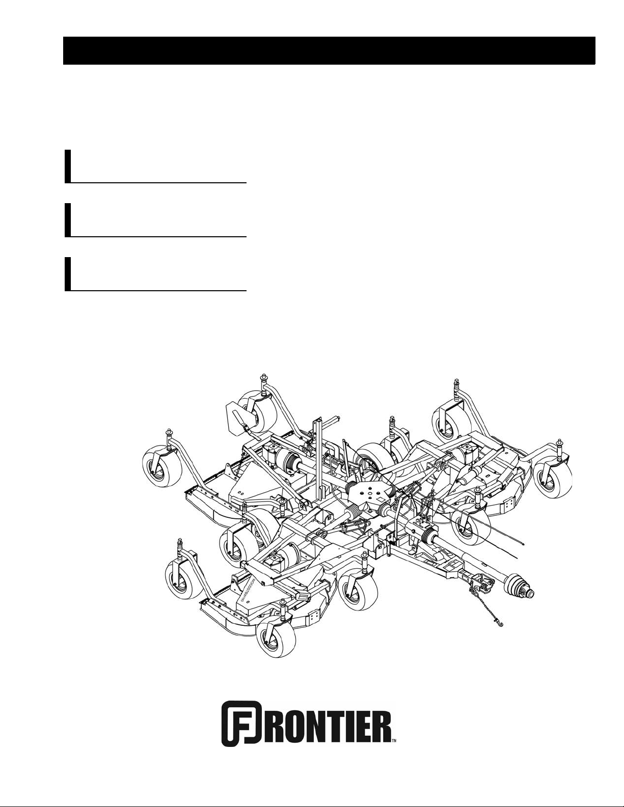
OPERATOR’S MANUAL
FM1012
FM1015
FM1017
REAR DISCHARGE
Serial Number 1XFFM10XAB0000106 & Above
GROOMING MOWERS
5WPMAN0862 (Rev. 10/30/2012)
Page 2

TO THE DEALER:
Assembly and proper installation of this prod uct is the responsib ility of the Frontier dea ler. Read manual instructions
and safety rules. Make sure all item s on the Dealer ’s Pre- Delivery and Delivery Che ck Lists in the Ope rator ’s Manual
are completed before releasing equipment to the owner.
TO THE OWNER:
Read this manual before ope rating yo ur Fron tier e quipment. T he info rmation pres ented wi ll prepare you to do a better
and safer job. Keep thi s manual handy for ready referenc e. Require all operators to read this m anual carefully and
become acquainted with all the adjustment and operating procedures before attempting to operate. Replacement
manuals can be obtained from your selling dealer.
The equipment you have purchased has been carefully engineered and manufactured to provide dependable and
satisfactory use. Like all mechanical products, it will require cleaning and upkeep. Lubricate the unit as specified.
Observe all safety information in this manual and safety decals on the equipment.
For service, your authori zed Fro ntier deal er has train ed mech anics , genui ne Front ier se rvice parts, and the nec essa ry
tools and equipment to handle all your needs.
Use only genuine Frontier service parts. Substitute parts will void the warranty and may not meet standards required for
safe and satisfactory operation. Record the model number and serial number of your equipment in the spaces
provided:
Model: ______________________________ Date of Purchase: _____________________
Serial Number: (see Safety Decal section for location) ____________________________________
Provide this information to your dealer to obtain correct repair parts.
Throughout this manual, the ter m NOTICE is used to indicate that failure to observe can cause damage to equipment.
The terms CAUTION, WARNING and DANGER are used in conju nction with the Safety- Alert Symb ol, (a triangl e with
an exclamation mark), to indicate the degree of hazard for items of personal safety.
2 Introduction
Frontier (Rev. 12/5/2011)
Page 3

TABLE OF CONTENTS
Si no lee Ingles, pida ayuda a
alguien que si lo lea para que le
traduzca las medidas de seguridad.
LEA EL INSTRUCTIVO!
!
INTRODUCTION. . . . . . . . . . . . . . . . . . . . . . . . . . . . . . . . . . . . . . . . . . . . . . 2
SPECIFICATIONS. . . . . . . . . . . . . . . . . . . . . . . . . . . . . . . . . . . . . . . . . . . . . 3
GENERAL INFORMATION . . . . . . . . . . . . . . . . . . . . . . . . . . . . . . . . . . . . . . 4
SAFETY RULES . . . . . . . . . . . . . . . . . . . . . . . . . . . . . . . . . . . . . . . . . . . . . . 5
SAFETY DECALS . . . . . . . . . . . . . . . . . . . . . . . . . . . . . . . . . . . . . . . . . . . . . 9
OPERATION . . . . . . . . . . . . . . . . . . . . . . . . . . . . . . . . . . . . . . . . . . . . . . . . 13
OWNER SERVICE . . . . . . . . . . . . . . . . . . . . . . . . . . . . . . . . . . . . . . . . . . . 19
TROUBLESHOOTING . . . . . . . . . . . . . . . . . . . . . . . . . . . . . . . . . . . . . . . . 25
DEALER SERVICE . . . . . . . . . . . . . . . . . . . . . . . . . . . . . . . . . . . . . . . . . . . 27
ASSEMBLY . . . . . . . . . . . . . . . . . . . . . . . . . . . . . . . . . . . . . . . . . . . . . . . . . 34
PARTS LISTS . . . . . . . . . . . . . . . . . . . . . . . . . . . . . . . . . . . . . . . . . . . . . . . 39
BOLT TORQUE CHART . . . . . . . . . . . . . . . . . . . . . . . . . . . . . . . . . . . . . . . 61
BOLT SIZE CHART & ABBREVIATIONS . . . . . . . . . . . . . . . . . . . . . . . . . . 62
INDEX . . . . . . . . . . . . . . . . . . . . . . . . . . . . . . . . . . . . . . . . . . . . . . . . . . . . . 63
SPECIFICATIONS
MODEL FM1012 FM1015 FM1017
Cutting Width 12’ 15’ 17’
Cutting Height Range 1.0” - 5.0” 1.0” - 5.0” 1.0” - 5.0”
Shipping Weight (Approximately ) 3,010 lbs. 3,300 lbs. 3,450 lbs.
Blade Speed (feet per minute) 18,000 18,000 18,000
Blade Spindles 7 9 9
Number of Blades 7 9 9
Universal Drive Series (Input: ASAE Cat 4; Wing: ASAE Cat 3)
Transport Wheels 20.5” x 8.0” - 10 20.5” x 8.0” - 10 20.5” x 8.0” - 10
Caster Wheels 15” x 6.00” - 6 18” x 9.50” - 8 18” x 9.50” - 8
Tractor PTO Speed 540 rpm 540 rpm 540 rpm
Recommended Minimum
Tractor Horsepower 30 hp 35 hp 40 hp
5WPMAN0862 (11/22/2010)
Introduction 3
Page 4

GENERAL INFORMATION
WARNING
■ Some illustrations in this manual show the
mower with safety shields removed to provide a
better view. The mower should never be operated
with any safety shielding removed.
The purpose of this manual is to assist you in operating
and maintaining your Flex Wi ng Mower. Read it carefully. It furnishes information and instructions that will
help you achieve years of dependable performance.
These instruction s have been compiled from extensi ve
field experience and engineering data. S ome information may be general in nature, due to unknown and
varying operatin g con dition s. Howe ver, through exp eri-
ence and these instructions, you should be able to
develop procedures suitable to your particular situation.
The illustrations and data used in this manual were current at the time of printing. However, due to possible
inline production changes, your machine may vary
slightly in detail. We reserve the right to redesign and
change the machines as may be necessary without
notification.
Throughout this m anual, references are made to right
and left direction. These are determined by standing
behind the tractor facing the dir ection of for ward travel.
Blade rotation is clockwise as viewed from the top of
the mower.
NOTES
4 Introduction
5WPMAN0862 (11/22/2010)
Page 5

TRAINING
Safety is a primary concern in the design and
manufacture of our products. Unfortunately, our
efforts to provide safe equipment can be wiped
out by an operator’s single careless act.
In addition to the design and configuration of
equipment, hazard control and accident prevention are dependent upon the awareness, concern,
judgement, and proper training of personnel
involved in the operation, transpor t, maintenanc e
and storage of equipment.
It has been said “The best safety device is an
informed, careful operator.” We ask you to be that
kind of operator.
SAFETY RULES
ATTENTION! BECOME ALERT! YOUR SAFETY IS INVOLVED!
Safety instructions are important! Read all
attachment and power unit manuals; follow all
safety rules and safety decal information. (Replacement manuals and safety decals are a vailable from
your dealer.) Failure to follow instructions or safety
rules can result in serious injury or death.
If you do not understand any part of this manual
and need assistance, see your dealer.
Know your controls and how to stop engine and
attachment quickly in an emergency.
Operators must be instruct ed in and be ca pable
of the safe operation of the equipment, its attachments, and all controls. Do not allow anyone to
operate this equipment without proper instructions.
Keep hands and body away from pressurized
lines. Use paper or cardboard, not hands or other
body parts to check for leaks. Wear safety goggles.
Hydraulic fluid under pressure can easily penetrate
skin and will cause serious injury or death.
Make sure that all operating and service personnel know that if hyd raulic fluid pe netrates s kin, it
must be surgically removed as soon as possible by
a doctor familiar with this form of injury or gangrene, serious injury, or death will result. CONTACT A PHYSICIAN IMMEDIATELY IF FLUID
ENTERS SKIN OR EYES. DO NOT DELAY.
Never allow children or untrained persons to
operate equipment.
Frontier FM (Rev. 1/31/2007)
PREPARATION
Check that all hardware is properly installed.
Always tighten to torque chart specif ications
unless instructed otherwise in this manual.
Air in hydraulic systems ca n cau se er ratic o peration and allows loads or equipment components
to drop unexpectedly. When connecting equipment
or hoses or performing any hydraulic maintenance,
purge any air in hydraulic system by operating all
hydraulic functions several times. Do this before
putting into service or allowing anyone to
approach the equipment.
Make sure all hydraulic hoses, fittings, and
valves are in good condition and not leaking before
starting power unit or using equipment. Check and
route hoses carefully to prevent damage. Hoses
must not be twisted, bent sharply, kinked, frayed,
pinched, or come into c ontact with any moving
parts. Operate moveable components through full
operational range to check clearances. Replace
any damaged hoses immediately.
Always wear relatively tight and belted clothing
to avoid entanglement in moving parts. Wear
sturdy, rough-soled work shoes and protective
equipment for eyes, hair, hands, hearing, and head;
and respirator or filter mask where appropriate.
When attaching a pull-type unit to the tractor
drawbar, always use a high-strength drawbar pin.
The drawbar pin must have a device that will lock it
into position. Secure safety chain to attachment
and tractor.
Make sure attachment is properly secured,
adjusted, and in good operating condition.
Make sure spring-activat ed locking pin or collar
slides freely and is seated firmly in tractor PTO
spline groove.
If equipped with driveline guard tether chains,
make sure they are attached to the tractor and
equipment as shown in the pamphlet that acc ompanies the driveline. Replace if damaged or broken.
Check that driveline guards rotate freely on driveline before putting equipment into service.
Before starting the power unit, check all equipment driveline guards for d amage. Replace any
damaged guards. Make sure all guards rotate freely
on all drivelines. If guards do not rotate freely on
drivelines, repair and replace bearings before putting equipment into service.
(Safety Rules continued on next page)
Safety 5
Page 6

(Safety Rules continued from previous page)
SAFETY RULES
ATTENTION! BECOME ALERT! YOUR SAFETY IS INVOLVED!
Power unit must be equipped with ROPS or
ROPS cab and seat belt. Keep seat belt securely
fastened. Fallin g off power unit can result in death
from being run over or crushed. Keep foldable
ROPS systems in “locked up” position at all times.
Inspect chain shielding before each use.
Replace if damaged.
Remove accumulated debris from this equipment, power unit, and engine to avoid fire hazard.
Make sure all safety decals are installed.
Replace if damaged. (See S af ety D ecals section for
location.)
Make sure shields and guards are properly
installed and in good condition. Replace if damaged.
A minimum 20% of tractor and equipment
weight must be on the tractor front wheels when
attachments are in transport position. Without this
weight, tractor could tip over, causing personal
injury or death. The weight may be attained with
front wheel weights, ballast in tires or front tractor
weights. Weigh the tractor and equipment. Do not
estimate.
Inspect and clear area of stones, branches, or
other hard objects that might be thrown, causing
injury or damage.
Never attach the mower release rope to the
operator, the operator's clothing, or the tractor
seat.
Make test turns, both left and right. Ch eck that
both the hydraulic hose and the mower transport
lock release rope do not become taut or caught on
any parts of the tractor or mower.
Never tow this implement with a motor vehicle.
OPERATION
Only engage power when equipment is at
ground operating level. Always disengage power
when equipment is raised off the ground.
Do not allow bystanders in the area wh en operating, attaching, removing, assembling, or servicing equipment.
Never walk, stand, or place yourself or others
under a raised wing or in the path of a lowering
wing. Hydraulic system leak-down, hydraulic system failures, mechanical failures, or movement of
control levers can cause wings to drop unexpectedly and cause severe injury or death.
Full chain shielding must be installed when
operating in populated areas or other areas where
thrown objects could injur e people or damage
property.
• If this machine is not equipped with full chain
shielding, operation must be stopped when anyone comes within 300 feet (92 m).
• This shielding is designed to reduce the risk
of thrown objects. The mower deck and protective devices cannot prevent all objects from
escaping the blade enclosure in ev ery mowing
condition.
and escape, traveling as much as 300 feet (92 m).
Never direct discharge toward people, animals,
or property.
Do not operate or transport equipment while
under the influence of alcohol or drugs.
It is possible for objects to ricochet
TRANSPORTATION
The maximum transport speed for towed and
semi-mounted machines is 20 mph (32 km/h).
Regardless of the maximum speed capability of the
towing tractor, do not exceed the implement’s maximum transport speed. Doing so could result in:
• Loss of control of the implement and tractor
• Reduced or no ability to stop during braking
• Implement tire failure
• Damage to the implement or its components.
Use additional caution and reduce speed when
under adverse surface conditions, turning, or on
inclines.
Do not operate PTO during transport.
6 Safety
Operate only in daylight or good artificial light.
Keep hands, feet, hair, and clothing away from
equipment while engine is running. Stay clear of all
moving parts.
Always comply with all state and local lighting
and marking requirements.
Never allow riders on power unit or attachment.
Power unit must be equipped with ROPS or
ROPS cab and seat bel t. Keep seat belt secu rely
fastened. Falling off power unit can result in death
from being run over or crushed. Keep foldable
ROPS systems in “locked up” position at all times.
(Safety Rules continued on next page)
Frontier FM (Rev. 1/31/2007)
Page 7

(Safety Rules continued from previous page)
SAFETY RULES
ATTENTION! BECOME ALERT! YOUR SAFETY IS INVOLVED!
Always sit in power unit seat when operating
controls or starting engine. Secu rely faste n seat
belt, place transmission in neutral, engage brake,
and ensure all other controls are disengaged
before starting power unit engine.
Operate tractor PTO at 540 RPM. Do not exceed.
Do not modify or alter or permit anyone else to
modify or alter the equipment or any of its components in any way.
Your dealer can supply original equipment
hydraulic accessories and repair parts. Substitute
parts may not meet original equipment specifications and may be dangerous.
Do not operate mowers on terrain that raises
mowers beyond 25 degrees. Exceeding this design
limit will result in U-joint “knocking noise” and
potential driveline failure and could cause driveline
to pull apart.
Before raising or lowering wings, front hitch/lift
and rear wheel/lift cylinders must be fully extended
and all four cylinder locks installed. This prevents
rotor and bearing support damage that can result
from ground contact.
Look down and to the rear and make sure area
is clear before operating in reverse.
Do not operate or transport on steep slopes.
Do not stop, start, or change directions sud-
denly on slopes.
Use extreme care and reduce ground speed on
slopes and rough terrain.
Watch for hidden hazards on the terrain during
operation.
Stop power unit and implement immediately
upon striking an obstruction. Dismount power unit,
using proper procedure. Inspect and repair any
damage before resuming operation.
Always connect safety ch ain from equip ment to
towing vehicle when transporting.
MAINTENANCE
Before dismounting power unit or performing
any service or maintenance, follow these steps:
disengage power to equipment, lower the 3-point
hitch and all raised c omponents to the ground,
operate valve levers to release any hydraulic pressure, set parking brake, stop engine, r emove key,
and unfasten seat belt.
Before working underneath, carefully read Operator’s Manual instructions, disconnect driveline,
raise mower, securely block up all cor ners with
jackstands, and check stability. Secure blocking
prevents equipment from dropping due to hydraulic leak down, hydraulic system failures, or
mechanical component failures.
To prevent contamination, clean and then cover
hose ends, fittings, and motor ports with tape.
Always wear relatively tight and belted clothing
to avoid entanglement in moving parts. Wear
sturdy, rough-soled work shoes and protective
equipment for eyes, hair, hands, hearing, and head;
and respirator or filter mask where appropriate.
Do not allow bystanders in the area wh en operating, attaching, removing, assembling, or servicing equipment.
Make sure attachment is properly secured,
adjusted, and in good operating condition.
Keep all persons away from operator control
area while performing adjustments, service, or
maintenance.
Frequently check blades. They should be sharp,
free of nicks and cracks, and securely fastened.
Do not handle blades with bare hands. Careless
or improper handling may result in serious injury.
Your dealer can supply genuine replacement
blades. Substitute blades may not meet original
equipment specifications and may be dangerous.
Tighten all bolts, nuts and screws to torque
chart specifications. Check that all cotter pins ar e
installed secu rely to ensu re eq uipme nt is i n a sa fe
condition before putting unit into service.
Make sure all safety decals are installed.
Replace if damaged. (See S afety Deca ls se ct ion fo r
location.)
Make sure shields and guards are properly
installed and in good condition. Replace if damaged.
Do not disconnect hydraulic lines until engine is
stopped, power unit is properly secured, equipment and all components are lowered to the
ground, and system pressure is released by operating all valve control levers.
(Safety Rules continued on next page)
Frontier FM (Rev. 1/31/2007)
Safety 7
Page 8

(Safety Rules continued from previous page)
SAFETY RULES
ATTENTION! BECOME ALERT! YOUR SAFETY IS INVOLVED!
When lubricating telescoping PTO drives, keep
fingers out of shield access slots to prevent injury.
Wear gloves when installing belt. Be careful to
prevent fingers from being caught between belt
and pulley.
extended and, if released suddenly, can cause personal injury.
STORAGE
Block equipment securely for storage.
Use care when installing or removing belt from
spring-loaded idler. Springs store energy when
Keep children and bystanders away from storage area.
8 Safety
Frontier FM (Rev. 1/31/2007)
Page 9
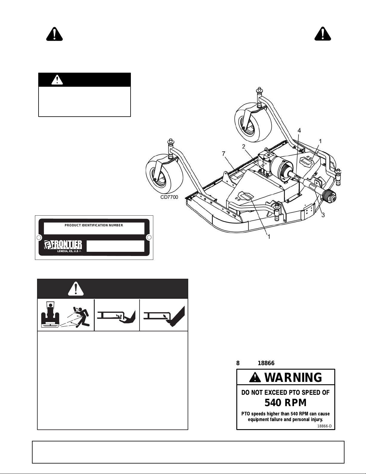
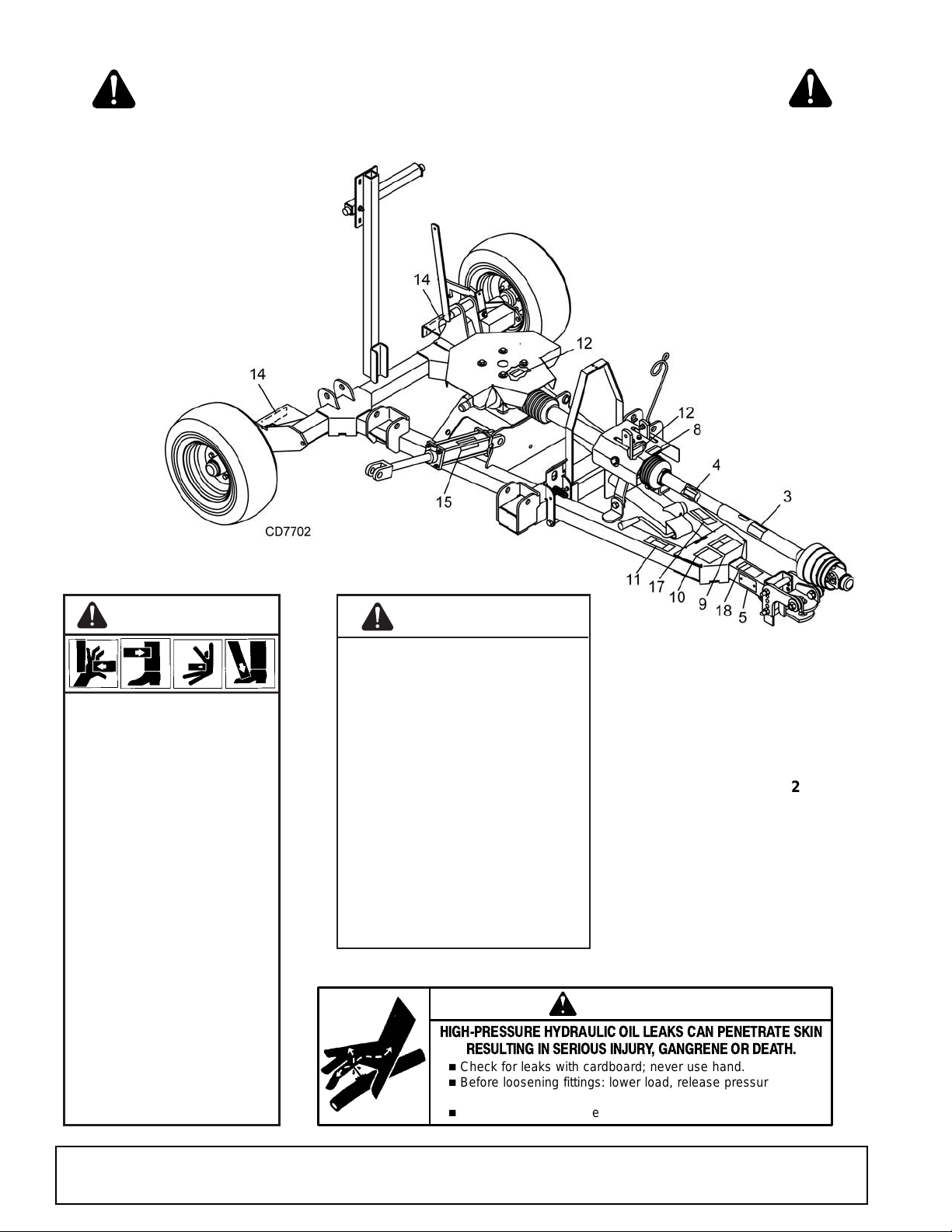
5 - Serial Number Plate
ROTATING BLADES AND
THROWN OBJECTS
Do not put hands or feet under or into mower when
engine is running.
Before mowing, clear area of objects that may be
thrown by blade.
Keep bystanders away.
Keep guards in place and in good condition.
BLADE CONTACT OR THROWN OBJECTS CAN
CAUSE SERIOUS INJURY OR DEATH.
DANGER
15503-C
2 - 5WP15503
SHIELD MISSING
DO NOT OPERATE
PUT SHIELD ON
DANGER
18867--B
1 -5WP18867
FM1015 & FM1017
REAR DECK
(FM1012 SIMILAR)
BE CAREFUL!
Use a clean, damp cloth to clean safety decals.
Avoid spraying too close to decals when using
a pressure washer; high-pressu re water can
enter through very small scratches or under
edges of decals causing them to peel or come
off.
Replacement safety decal s can be ordered free
from your dealer.
DO NOT EXCEED PTO SPEED OF
540 RPM
PTO speeds higher than 540 RPM can cause
equipment failure and personal injury.
WARNING
18866-D
8 - 5WP18866
LENEXA , K S, U. S.A.
SAFETY & INSTRUCTIONAL DECALS
ATTENTION! BECOME ALERT! YOUR SAFETY IS INVOLVED!
Replace Immediately If Damaged!
PRODUCT IDENTIFICATION NUMBER
LENEXA, KS, U.S.A.
5WPMAN0862 (11/22/2010)
Safety 9
Page 10
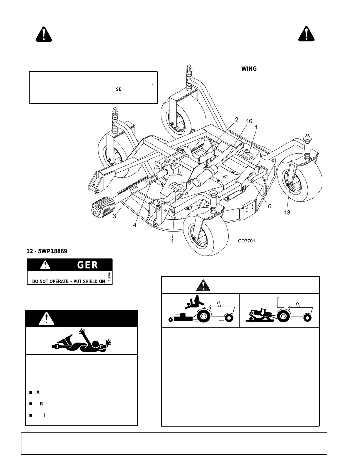
SAFETY & INSTRUCTIONAL DECALS
ROTATING DRIVELINE
CONTACT CAN CAUSE DEATH
KEEP AWAY!
DO NOT OPERATE WITHOUT--
n
ALL DRIVELINE GUARDS, TRACTOR AND
EQUIPMENT SHIELDS IN PLACE
n
DRIVELINES SECURELY ATTACHED AT
BOTH ENDS
n
DRIVELINE GUARDS THAT TURN FREELY
ON DRIVELINE
DANGER
18864B
3 - 5WP18864
FALLING OFF CAN RESULT IN BEING RUN OVER.
Tractor must be equipped with ROPS (or ROPS CAB) and seat
belt. Keep foldable ROPS systems in “locked up” position at all
times.
Buckle Up! Keep seat belt securely fastened.
Allow no riders.
RAISED EQUIPMENT CAN DROP AND CRUSH.
Before working underneath, follow all instructions and safety rules in
operator’s manual and securely block up all corners of equipment
with jack stands.
Securely blocking prevents equipment dropping from hydraulic leakdown, hydraulic system failures or mechanical component failures.
FALLING OFF OR FAILING TO BLOCK SECURELY CAN
RESUL T IN SERIOUS INJURY OR DEATH.
WARNING
18865--C
9 - 5WP18865
SHIELD MISSING
DO NOT OPERATE -- PUT SHIELD ON
DANGER
18869
12 - 5WP18869
WING DECK
IMPORTANT
OPERATINGMOWERS ATRAISED ANGLES EXCEEDING 25
•
WILL CREATE U-JOINT KNOCKING NOISE AND DAMAGE
DRIVELINE. FAILURESRESULTINGFROM THIS OPERATION
WILL NOT BE COVERED BY WARRANTY.
38446
16 - 5WP38446
13 - 5WP1002940 YELLOW
FRONT REFLECTOR
ATTENTION! BECOME ALERT! YOUR SAFETY IS INVOLVED!
Replace Immediately If Damaged!
10 Safety
5WPMAN0862 (11/22/2010)
Page 11
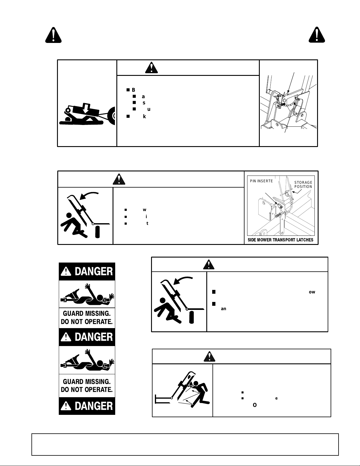
WARNING
PIN INSERTED TO LOCK
TRANSPORT LATCH
PIN STORAGE
POSITION
RAISED MOWER CAN DROP AND CRUSH
n
Before working underneath rear mower:
n
Raise rear mower to transport position.
n
Insert pin to lock transport latch.
n
Securely block up rear of mower. See manual.
n
Blocking up prevents mower dropping from
transport latch release or failure, hydraulic leak
down, or hydraulic system failures.
FAILURE TO FOLLOW INSTRUCTIONS CAN
RESUL T IN SERIOUS INJURY OR DEATH.
44650
WARNING
RAISED MOWERS CAN
DROP AND CRUSH
n
Keep away. Do not go underneath.
n
When raised, insert pins to lock transport latches.
n
Lower after transport.
FAILURE TO FOLLOW INSTRUCTIONS CAN
RESUL T IN SERIOUS INJURY OR DEATH.
SIDE MOWER TRANSPORT LATCHES
44651
PIN
STORAGE
POSITION
PIN INSERTED
TO LOCK
TRANSPORT
LATCH
WARNING
RAISED MOWERS EXPOSE
BLADES AND INCREASE
THROWN OBJECT HAZARDS
n
Only raise for transport.
n
Stop mowers before raising.
FAILURETO FOLLOW INSTRUCTIONS CAN
RESUL T IN SERIOUS INJURY OR DEA TH.
44656
17 - 5WP44656
11 - 5WP44651
7 - 5WP44650
6 - 5WP38421
RAISED MOWER CAN
DROP AND CRUSH
1
Before working underneath side mowers, lower
side mowers and securely block up. See manual.
1
Blocking up prevents mower dropping from
transport latch release or failure, hydraulic leak
down or hydraulic system failure.
FAILURE TO FOLLOW INSTRUCTIONS CAN
RESULT IN SERIOUS INJURY OR DEATH.
WARNING
38421-A
GUARD MISSING.
DO NOT OPERATE.
DANGER
33347E
DANGER
DANGER
GUARD MISSING.
DO NOT OPERATE.
4 - 5WP33347
SAFETY & INSTRUCTIONAL DECALS
ATTENTION! BECOME ALERT! YOUR SAFETY IS INVOLVED!
Replace Immediately If Damaged!
5WPMAN0862 (11/22/2010)
Safety 11
Page 12
ATTENTION! BECOME ALERT! YOUR SAFETY IS INVOLVED!
HIGH-PRESSURE HYDRAULIC OIL LEAKS CAN PENETRATE SKIN
RESULTING IN SERIOUS INJURY, GANGRENE OR DEATH.
n
Check for leaks with cardboard; never use hand.
n
Before loosening fittings: lower load, release pressure, and
be sure oil is cool.
n
Consult physician immediately if skin penetration occurs.
WARNING
19924-B
15 - 5WP19924
14 - 5WP57123 RED
REAR REFLECTOR
10 - 5WP18877
FM1015, FM1017, &
FM1012 TRAILER
18 - 5WP1002941
SAFETY & INSTRUCTIONAL DECALS
Replace Immediately If Damaged!
WARNING
CRUSHING AND
PINCHING HAZARD
Be extremely careful
handling various parts of the
machine. They are heavy and
hands, fingers, feet, and
other body parts could be
crushed or pinched between
tractor and implement.
Operate tractor controls from
tractor seat only.
Do not stand between tractor
and implement when tractor
is in gear.
Make sure parking brake is
engaged before going
between tractor and
implement.
Stand clear of machine while
in operation or when it is
being raised or lowered.
FAILURE TO FOLLOW THESE
INSTRUCTIONS COULD
RESULT IN SERIOUS INJURY
12 Safety
WARNING
TO AVOID SERIOUS
INJURY OR DEATH:
Read Operator's Manual (available
from dealer) and follow all safety
precautions.
Keep all shields in place and in good
condition.
Operate mower from tractor seat only.
Lower mower, stop engine and remove
key before dismounting tractor.
OR DEATH.
1002941-A
Allow no children or untrained persons
to operate equipment.
Do not transport towed or
semi-mounted units over 20 mph.
FAILURE TO OPERATE SAFELY
CAN RESULT IN
INJURY OR DEATH.
18877-C
5WPMAN0862 (11/22/2010)
Page 13

OPERATION
DANGER
WARNING
WARNING
CAUTION
WARNING
The operator is responsible for the safe operation of
the cutter. The operator must be properly trained.
Operators should be familiar with the cutter, the tractor,
and all safety prac ti ce s befo re s tarting operation. Read
the safety rules an d safety decals on page 5 through
page 12.
This mower is design ed for lawn and grass m owing. It
is not designed for rough conditions or heavy weed
mowing. It is equipped with suction type blades for best
results in lawn mowing.
Recommended mowing speed for most conditions is
from 2 to 5 mph. Always operate power unit PTO at
540 rpm.
This section provides information for attaching the
mower to the tractor and preparing it for field operation.
Review this data prior to tractor hook-up and operation.
Lower mower to the ground when not in use.
Full chain shielding must be installed when
operating in populated areas or other areas where
thrown objects could injure peop le or damage
property.
• If this machine is not equipped with full chain
shielding, operation must be stopped when anyone comes within 300 feet (92 m).
• This shielding is designed to reduce the risk
of thrown objects. The mower deck and protective devices cannot prevent all objects from
escaping the blade enclosure in every mowin g
condition.
and escape, traveling as much as 300 feet (92 m).
It is possible for objects to ricochet
Make sure spring-activat ed locking pin or collar
slides freely and is seated firmly in tractor PTO
spline groove.
Operate tractor PTO at 540 RPM. Do not exceed.
Stop power unit and implement immediately
upon striking an obstruction. Dismount power unit,
using proper procedure. Inspect and repair any
damage before resuming operation.
Always wear relatively tight and belted clothing
to avoid getting caught in moving parts. Wear
sturdy, rough-soled work shoes and protective
equipment for eyes, hair, hands, hearing, and head;
and respirator or filter mask where appropriate.
ATTACHING MOWER TO T RACTOR
Make sure spring-activat ed locking pin or collar
slides freely and is seated firmly in tractor PTO
spline groove.
Make sure shields and guards are properly
installed and in good condition. Replace if damaged.
Never attach the mower release rope to the
operator, the operator's clothing, or the tractor
seat.
1. Park m ower and tractor on a level, hard-surfa ced
area.
Before dismounting power unit or performing
any service or maintenance, follow these steps:
disengage power to equipment, lower the 3-point
hitch and all raised c omponents to the ground,
operate valve levers to release any hydraulic pressure, set parking brake, stop engine, r emove key,
and unfasten seat belt.
Never allow riders on power unit or attachment.
Never allow children or untrained persons to
operate equipment.
Keep bystanders away from equipment.
5WPMAN0862 (11/11/2010)
2. Adju st tractor hitch bracke t on trailer frame so th e
trailer is level wh en attached to the tra ctor. Pin the
mower to the tractor.
NOTE: When attaching mower to tractor drawbar,
make sure the co rrec t dr awba r pi n i s us ed. A Cat ego ry
1 drawbar is 1"; Catego ry 2 is 1.25". Fai lure to use th e
correct pin size will result in premature wear of hitch
and drawbar hole. If the hitch on the mower doesn't
match your tractor drawbar, contact your dealer to
order the correct size hitch for your tractor. If mower
will be attached to tractor for a long period of time,
secure hitch to drawbar using a bolt, locknut, and
washers assembled tightly. This will reduce wear on
drawbar and hitch.
A 1-3/8" 6B spline PTO shaft is used for connecting the
mower to the tractor. This mower is designed for 540
rpm PTO only.
Operation 13
Page 14
The PTO drive shaft is intended for use with tractors
that have 14 inches betwe en the end of the PTO shaft
and the tractor's drawbar hitch pin hole.
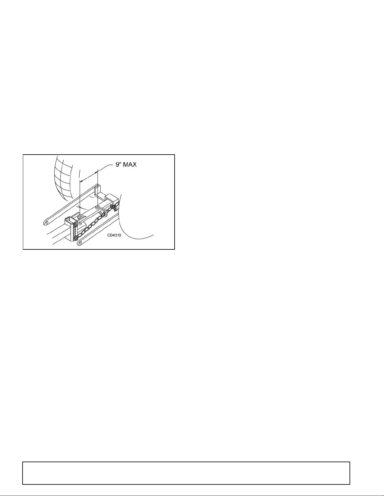
3. Attach the safety chai n to the tractor as shown in
Figure 1.
4. Attach the mower driv e shaft to tractor PTO. Make
sure the lock collar engages securely.
CV Driveline Turning Limits
NOTICE
■ Do not exceed turning angle of 80 degrees at
the head of the Constant Velocity (CV) driveline or
damage will occur.
Check for excessive turn angle:
5. Attach the end of the mower’s transport lock
release rope to a location on the tractor within easy
reach of the operator.
NOTE: When routing the rope, do not route through the
hydraulic hose guide and do not allow rope slack to
drop between the driveline shields and the gearbox
rotati n g sh afts.
Figure 1. To w Chain Installati on
Attaching Hydraulic Hoses
1. Attach the hydraulic hose from the mower to the
tractor.
2. Route the hose through the hose guide of the
trailer frame and be sure the hose can slide freely
in the guide. Do not allow hose slack to drag on the
ground or become caught on tractor protrusions.
3. From the operat or position, start the tractor, raise
and lower the wings, and the rear deck several
times. This will purge the hydraulic cylinders and
hoses of trapped air.
Interference Check
1. Be sure that the tractor 3-point arms do not
interfere with hydraulic hoses, driveline or mower
frame.
2. Check for strai ght ahead operati on and full turn ing
angles. If there is any interfe rence, remove the 3point arms.
NOTE: Contact between 3-point arms and mower
can cause damage, especially when turning.
1. Disconnect the driveline from the tractor.
2. Start engine and turn as far right or left as possible.
3. Shut off the engine and connect the CV driveline to
the tractor. If it cannot be connected, the turn angle
is too severe.
4. Restart the tractor and straighten the angle slightly.
5. Shut off the engine and connect the CV driveline to
tractor.
6. Repeat the process until the driveline can be
connected. The po int at which the drivel ine can b e
connected is the maximum turn that can be made.
Leveling Mower
NOTE: To ensure satisfac tory mo wer performance, the
trailer frame and decks must be leveled befo re operating the mower. During normal operation, the mower
should be leveled twice each season. The mower must
be leveled each time a tractor with a d ifferent drawbar
height is used.
Follow this procedure to level the mower for operatio n:
1. Park the tractor and mower on a fla t level surface
with the decks in mowing position.
2. Inflate all tires to the recommended pressure: 70
psi for trailer tires and 30 psi for deck gauge tires.
3. Level th e trailer frame b y adjusting t he hitch. (See
Figure 2.)
4. Remove the hitch clevis from the trai ler frame and
pin to the tractor drawbar.
5. Use the parkin g jack to adjust the trailer frame to
the level position. Align the nearest hitch
adjustment hole in the hitch clevis with a hole in the
trailer frame.
6. Tighten the hardware to specifications in the Bolt
Torque Chart on page 61. Readju st the le vel of th e
frame each time the drawbar height changes.
7. Attach the mo wer and the driveline to the tractor.
Level the driveline by placing a bolt through the
carrier bearing and the d riveline hei ght adjustment
holes.
14 Operation
5WPMAN0862 (11/22/2010)
Page 15
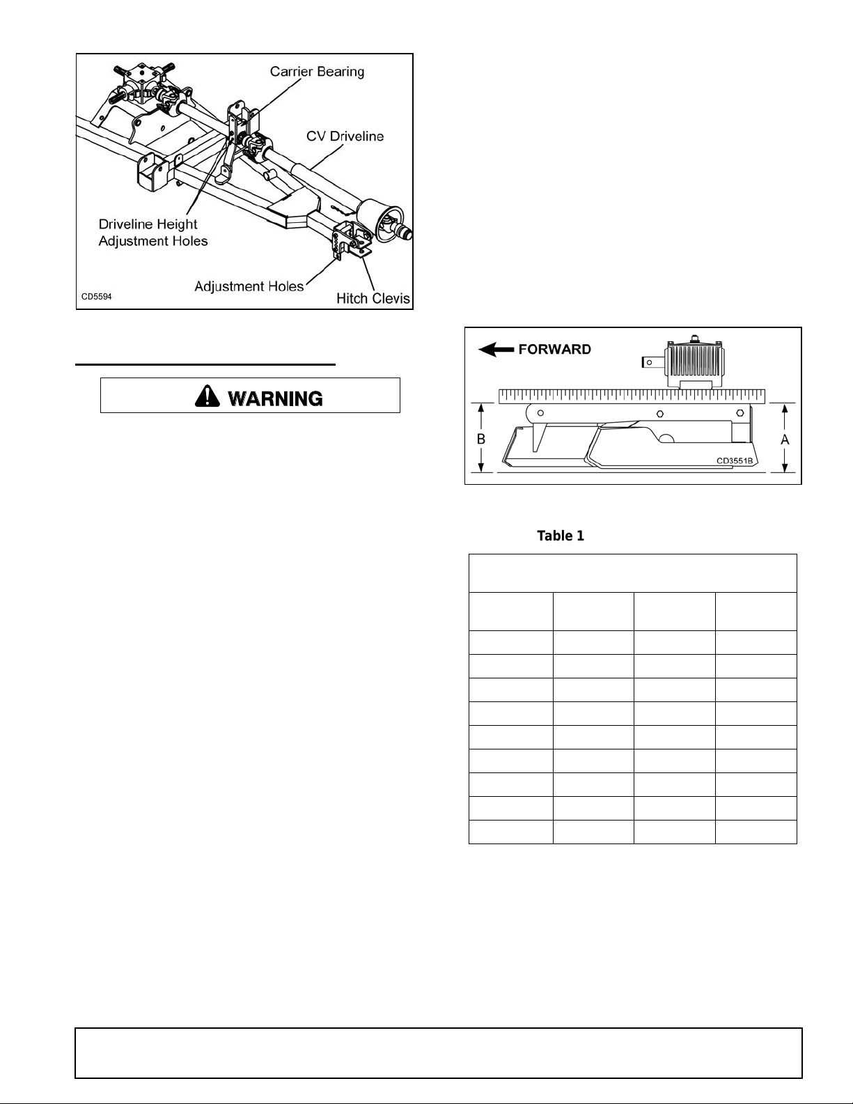
Figure 2. Level Trailer Frame
WARNING
Table 1: Cutting Height Chart
Spacers Required Under
Caster Arm Pivot Tube
Cut
Height
1/2"
Spacer
3/4"
Spacer
1
Spacer
1"
1-1/2" 1
2" 1
2-1/2" 1 1
3" 2
3-1/2" 1 2
4" 1 2 1
4-1/2" 2 2
5" 1 2 2
CUTTING HEIGHT ADJUSTMENT
Keep all persons away from operator control
area while performing adjustments, service, or
maintenance.
4. Set mower on the ground.
5. Retighten cap screws. This equalizes the
clearance in the bolt holes.
6. Best mowing results will be obtained with front of
mower level with, or slightly lower than, the rear.
7. Cutting height is controlled with front and rear
caster wheel adjustment.
8. To raise rear of mower, move caster adjustment
spacers under caster arms.
9. To raise f ront of mower, move spacers under front
caster wheel arms.
Remember, measurement at location A (Figure 3)
should not be less than locat ion B and should not be
over 1/2" greater than location B
Before working underneath, carefully read Operator’s Manual instructions, disconnect driveline,
raise mower, securely block up all cor ners with
jackstands, and check stability. Secure blocking
prevents equipment from dropping due to hydraulic leak down, hydraulic system failures, or
mechanical component failures.
NOTICE
■ Avoid low cutting heights. Striking the ground
with blades produces one of the most damaging
shock loads a mower can encounter. Allowing
blades to contact ground repeatedly will cause
damage to mower and drive.
1. Level mower from side to side. Check by
measuring from mower frame to the ground at
each deck rail.
2. Verify that the same amount of spacers ar e under
all caster arms.
3. Loosen cap screws that attach caster arm
assembly to deck.
Figure 3. Cutting Height Adjustment
5WPMAN0862 (11/11/2010)
Operation 15
Page 16
TRANSPORT
WARNING
CAUTION
WARNING
When transporting the mower short distances, raise
the wings and the rear deck until all three transport
locks engage automat ical ly.
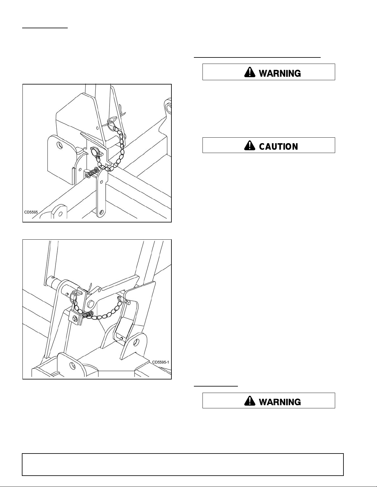
Install locking pins to secure the mower wings for
transport as shown in Figure 4 and Figure 5.
Figure 4. Lock Pin Installed (Right Wing)
3. Pull the transport lock release rope to disengage
the locks. Lower the wings and rear deck and
release the rope.
STARTING AND STOPPING MOWER
Do not operate PTO during transport.
Never direct discharge toward people, animals,
or property.
Keep hands, feet, hair, and clothing away from
equipment while engine is running. Stay clear of all
moving parts.
Stop power unit and implement immediately
upon striking an obstruction. Dismount power unit,
using proper procedure. Inspect and repair any
damage before resuming operation.
Always sit in power unit seat when operating
controls or startin g engine. Se curely fast en seat
belt, place transmission in ne utral, engage brake,
and ensure all other cont rols are disengaged
before starting power unit engine.
NOTICE
■ Stopping the mower with belt in contact with a
very hot pulley will bake and ruin belt.
Figure 5. Lock Pin Storage Installed
(Rear Deck)
To lower the wings and the rear deck:
1. Remove the locking pins and store in holes
provided.
2. Slightly raise the wings and rear deck to take
pressure off the locking mechanisms.
Power for operating the mower is supplied from the
tractor PTO. Refer to your tractor manual for instructions on engaging and disengaging the PTO.
Operate PTO at 540 rpm. Know how to stop tractor and
mower quickly in case of an emergen cy.
If the mower becomes plugged causing the belt to slip
for over two seconds, follow these steps:
1. Raise mower just enough to clear accumulated
material.
2. Continue running at least two minutes, allowing
pulleys to cool.
To reduce the risk of thrown obj ects, do not raise the
mower higher than necessary
OPERATING
Do not operate mowers on terrain that raises
mowers beyond 25 degrees. Exceeding this design
limit will result in U-joint “knocking noise” and
potential driveline failure and could cause driveline
to pull apart.
16 Operation
5WPMAN0862 (11/22/2010)
Page 17
When engaging the PTO, engine rpm should always be
CAUTION
WARNING
WARNING
low. Once engaged and ready for mowing, increase
PTO speed to 540 rpm and main tain speed throug hout
the cutting operation.
Mower vibration tends to loosen bolts. All hardware
should be checked regular ly to m aintain prop er tor que.
Each time the mower is used, che ck al l ha rdwar e to b e
sure it is secure. Recommended torque values can be
found on page 61.
Extremely tall material sh ould be cut twi ce. Set mower
at a higher cutting he ight for the first pass. Then cut a t
desired height 90 degrees to the first pass.
Remember, sharp blades produce cleaner cuts and
require less power.
Analyze area to be cut to determine the best procedure. Consider height and type of grass and terrain
type: hilly, level, or rough.
The condition of the terrain will determine cutting
results. For best results, mower blades should be kept
sharp at all times and the pla tform as leve l as poss i ble .
When mower blades show excessive wear, they
should be replaced.
Operating Technique
Stop power unit and implement immediately
upon striking an obstruction. Dismount power unit,
using proper procedure. Inspect and repair any
damage before resuming operation.
Proper ground speed will depen d upon the t errain, the
height, type, and density of material to be cut.
Normally, ground speed will range from two to five
mph. Tall dense mate rial should b e cut a t a low sp eed;
thin medium-height material can be cut at a faster
ground speed.
Always operate tractor PTO at 540 rpm to maintain
proper blade speed and produce a clean cut.
Under certain conditions, tractor tires may roll some
grass down and prevent it from being cu t at the same
height as the surrounding area. When this occurs,
reduce your ground speed, but maintain PTO at 540
rpm. The lower ground speed will permit grass to partially rebound.
Uneven Terrain
Do not operate or transport on steep slopes.
Do not stop, start, or change directions sud-
denly on slopes.
Use extreme care and reduce ground speed on
slopes and rough terrain.
Watch for hidden hazards on the terrain during
operation.
In extremely uneve n terrain, rear wheel weights, front
tractor weights and/or front tire ball ast should be used
to improve stability.
Pass diagonally through sharp dips and avoid sharp
drops to prevent “hanging up” the tractor and the
mower. Practice will improve your skills in maneuvering
rough terrain.
Avoid sudden starts and stops when traveling up or
down hill.
Always mow down slopes, never up or across the face.
Avoid operating on steep slopes.
Slow down on sharp turns and slopes to prevent tipping and losing control.
In general, lower cu tting heights give a mo re even cut
with less tende ncy to leave tire tracks. Howev er, it is
better to cut grass frequently rather than too short.
Short grass deteriorates rapidly in hot weather and
invites weed growth during growing seasons. Follow
local recommendations for the suitable cutting height in
your area.
Operating Tips
Inspect and clear area of stones, branches, or
other hard objects that might be thrown, causing
injury or damage.
5WPMAN0862 (11/11/2010)
REMOVING MOWER FROM TRACTOR
1. Park the unit on a level, hard surface with the
wings and rear deck fully lowered to the ground.
2. Block the wheels to keep the mower from rolling
when unhitched from tractor.
3. Attach the jack to the si de of th e tong ue an d adj us t
the height to take the weight off the tractor hitch.
4. Disconn ect the PTO shaft and the hydraulic hose,
untie the mower transport lock release rope from
the tractor, and remove the hitch pin.
5. Store the PTO shaft end and the hydraulic hose
couplings off the ground and keep them clean.
Operation 17
Page 18

PRE-OPERATION CHECK LIST
(OWNER's RESPONSIBILITY)
___ Review and follow all safety rules and safety
decal instructions on pages 5 through 12.
___ Check that all sa fety decals are installed and in
good condition. Replace if damaged.
___ Check that all shields and guards are properly
installed and in good condi tion. Replace if damaged.
___ Check that chain shielding is in good condition
and replace any damaged chain links.
___ Check that all hardware and c otte r pin s ar e p ro p-
erly installed and secured.
___ Check to ensure blades are sharp, in good condi-
tion, and installed correctly. Replace if damaged.
___ Check that equipment is properly and securely
attached to tractor.
___ Make sure driveline spring-activated locking pin
or collar slides freely and is seated fi rmly in tractor PTO spline groove.
NOTES
___ Make sure the driv elin e guards and tet her c hains
are in good conditi on. Guards must rotate freely
on driveline. Fasten tether chains as instructed to
the tractor and the equipment.
___ Inspect area and remove stones, branches or
other hard objects that might be thrown, ca using
injury or damage.
___ Do not allow riders.
___ Check all lubrication points and grease as
instructed in Lubrication Information, page 20.
Make sure the PTO slip joint is lubricated and that
the gearbox fluid levels are correct.
___ Check that all hydraulic hos es and fittings are in
good condition and not leaking before starting
tractor. Check that hoses are not twisted, bent
sharply, kinked, frayed or pulled tight. Replace
any damaged hoses immediately.
___ Make sure tractor ROPS or ROPS cab and sea t
belt are in good condition. Keep seat belt
securely fastened during operation.
___ Before starting engine, o perator must be in trac-
tor seat with seat belt fastened. Plac e transmis-
sion in neutral or park, engage brake and
disengage tractor PTO.
18 Operation
5WPMAN0862 (11/22/2010)
Page 19
OWNER SERVICE
DANGER
WARNING
CAUTION
The information in t his section is written for operato rs
who possess basic mechanical skills. If you need help,
your dealer has trained service technicians available.
For your protection, read and follow the safety information in this manual
Always wear relatively tight and belted clothing
to avoid getting caught in moving parts. Wear
sturdy, rough-soled work shoes and protective
equipment for eyes, hair, hands, hearing, and head;
and respirator or filter mask where appropriate.
Full chain shielding must be installed when
operating in populated areas or other areas where
thrown objects could injure p eople or damage
property.
• If this machine is not equipped with full chain
shielding, operation must be stopped when anyone comes within 300 feet (92 m).
• This shielding is designed to reduce the risk
of thrown objects. The mower deck and protective devices cannot prevent all objects from
escaping the blade enclosure in ev ery mowing
condition.
and escape, traveling as much as 300 feet (92 m).
Keep hands and body away from pressurized
lines. Use paper or cardboard, not hands or other
body parts to c heck for leaks. Wear safety goggles.
Hydraulic fluid under pressure can easily penetrate
skin and will cause serious injury or death.
Make sure that all operating and service personnel know that if hyd raulic flui d penetrate s skin, it
must be surgically removed as soon as possible by
a doctor familiar with this form of injury or gangrene, serious injury, or death will result. CONTACT A PHYS ICIAN IMMEDIATELY IF FLUID
ENTERS SKIN OR EYES. DO NOT DELAY.
Keep all persons away from operator control
area while performing adjustments, service, or
maintenance.
Do not disconnect hydraulic lines until engine is
stopped, power unit is properly secured, equipment and all components are lowered to the
ground, and system pressure is released by operating all valve control levers.
Before dismounting power unit or perfor ming
any service or maintenance, follow these steps:
disengage power to equipment, lower the 3-point
hitch and all raised com ponents to the ground,
operate valve levers to release any hydraulic pressure, set parking brake, stop engine, remove key,
and unfasten seat belt.
It is possible for obj ects to ricochet
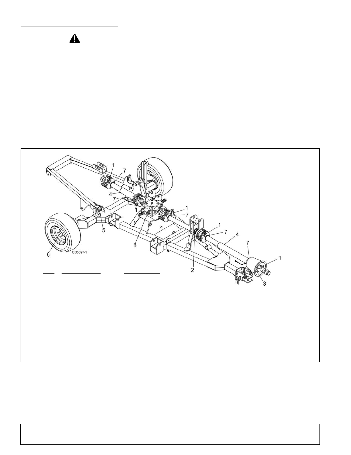
BLOCKING METHOD
The only approved b loc k ing d ev ic es fo r th is m ower ar e
jack stands with a load rating of 1,000 pounds or more.
Twelve jack stands, located as shown in Figure 6, must
be installed before working underneath this unit.
Figure 6. Jackstand Placement
Do not work underneath mower unless it is properly
attached to tractor and blocked securely. When properly attached, the unit will be anchored to minimize
front to rear movement.
Before blocking, be sure that the mower is securely
attached to the tractor. Lower mower units to the
ground. Raise the mower units as needed for working
room and securely block th em. Set tractor brakes, turn
engine off and remove key, then disconnect mower
driveline.
When blocking, yo u must consider the overall stability
of the unit. Just placing jac kstands under the unit will
not ensure your safety. The working surface must be
level and sol id t o sup port the l oaded weigh t of the ja ck
stands. Ensure that ja ckstands are stable at both top
and bottom. Before working under any portion of the
mower, test the stability of your blocking with the full
weight of the mower units lowered onto the jackstands.
5WPMAN0862 (11/22/2010)
Owner Service 19
Page 20
LUBRICATION INFORMATION
CAUTION
REF DESCRIPTION FREQUENCY
1 Driveline U-Joint 8 Hours
2 Drive Carrier Bearing 8 Hours
3 CV Body 8 Hours
4 Telescoping Shaft 8 Hours
5 Rear Deck Pivot Arm 8 Hours
6 Transport Wheel Hub 8 Hours
7 Shield Bearing 8 Hours
8 Splitter Gearbox (Fill 1/2 Check For Leaks Daily
full w/SAE 90W gear lube)
When lubricating telescoping PTO drives, keep
fingers out of shield access slots to prevent injury.
Do not let excess grease collect on or around parts,
particularly when operating in sandy areas.
Figure 7 and Figure 8 shows lubrication points. The
accompanying char ts give the frequency of lubrica tion
in operating hours , based on normal operating c onditions. Severe or unus ual conditions may require mo re
frequent lubrication.
Use a lithium grease of #2 consistency with a MOLY
(molybdenum disul fide) additi ve for all loc ations unle ss
otherwise noted.
Be sure to clean fittings thoroughly before attaching
grease gun. When a pplied accordin g to the lubrica tion
chart, one good pump of most guns is sufficient. Use
SAE 90W gear lube in gearboxes.
Daily lubrication of PTO slip joints is necessary. Failure
to maintain proper lubr ication can result in dama ge to
U-joints, gearboxes and/or dri ve shafts. Raise or lower
mower until grease fittings in PTO shields are exposed.
Insert grease gun thr ough slo ts and a pply g rease to all
sides of shafts. Always stand clear of m ower and wing
arm mechanism to avoid being pinched or crushed
should the mower or wing suddenly lower.
Raise and lower mower after a pplying greas e so that i t
spreads over the slip joint working area.
20 Owner Service
Figure 7. Lubrication Points - Trailer
5WPMAN0862 (11/22/2010)
Page 21

5WPMAN0862 (11/22/2010)
REF DESCRIPTION FREQUENCY
1 Caster Wheel Pivots 8 Hours
2 Caster Wheel Hubs 8 Hours
3 Blade Spindles 24 Hours
4 Gearbox (Fill 1/2 full with Check For Leaks Daily
SAE 90W gear lube
5 Driveline U-Joints 8 Hours
6 Wing Pivots 8 Hours
7 Telescoping Shaft 8 Hours
8 Shield Bearing 8 Hours
9 Deck Pivot 8 Hours
Figure 8. Lubrication Points - Deck
Owner Service 21
Page 22

BELT SERVICE
CAUTION
CAUTION
Belt Replacement
One of the major causes of belt failure is improper
installation. Before ins talling a new belt, check the following:
1. Check pulley shafts and bearings for wear.
2. Check pulley grooves for cleanliness.
3. Make sure spindles turn freely and without wobble.
If grooves require cle ani ng, moi sten a c lo th wi th a no nflammable, non-toxic deg reasing agent or commercial
detergent and water.
Avoid excessive force during installation. Do not use
tools to pry belt into pulley groov e. Do not roll be lt over
pulleys to install . This can cause hidden dam age and
premature belt failure.
Belt Installation
Wing Deck - FM1012 (Figure 9 & Figure 10)
Use care when installing or removing belt from
spring-loaded idler. Springs store energy when
extended and, if released suddenly, can cause personal injury.
4. Slid e belt under driv e pulley A and o ver idler arm.
Position the belt around drive pulley A.
5. Loose n the bolt holding belt guide G and swi ng it
away from pulley B. Route the belt around pulley D
as shown.
6. Make sure the belt is on drive pulley A; route
around idler F.
7. Grasp the belt between spindle pulley B and
spindle pulley D. Driv e pu lley A. P ull spring lo aded
idler with belt to obtain enoug h belt length to rout e
it over pulley B. Make sure spring loaded idler
pivots freely with belt installed.
8. Adjust belt guide G to provide 1/16" to 1/8"
clearance from belt. Tighten the bolt to 85 lbs./ft.
Figure 9. Belt Routing Right Wing FM1012
Rear Deck - FM1012
All Decks - FM1015 & FM1017(Figure 11)
Use care when installing or removing belt from
spring-loaded idler. Springs store energy when
extended and, if released suddenly, can cause personal injury.
1. Slide the belt under drive pulley A and over idler
arm. Position the belt around drive pulley A.
2. Loose n the bolt holding belt guide G and swi ng it
away from pulley B. Route the belt around pulley B,
idler C, and pulley D as shown.
3. Make sure the belt is on drive pulley A; route
around idler F.
4. Grasp the belt between spindle pulley E, spring
loaded idler F, and spindle pulley D. Pull spring
loaded idler with belt to obtain enough belt lengt h
to route it over p ulley E. Make sure spring loaded
idler pivots freely with belt installed.
Figure 10. Belt Routing Left Wing FM1012
22 Owner Service
5. Adjust belt guide G to provide 1/16" to 1/8"
clearance from belt. Tighten bolt to 85 lbs-ft.
5WPMAN0862 (11/22/2010)
Page 23

BLADE SHARPENING
WARNING
CAUTION
WARNING
CAUTION
NOTICE
■ When sharpening blades, be sure to balance
them. Unbalanced blades will cause excessive
vibration that can damage blade spindle bearings.
Vibration may also cause structural cracks in
mower housings.
1. Remove blades.
2. Always sharpen both ends to maintain balance.
Figure 11. Belt Routing - FM1015 & FM1017 All
Decks & FM1012 Rear Deck
BLADE SERVICING
Before servicing blades, raise and lock mower
in transport p ositio n, turn off engine , set parkin g
brake and remove key.
Keep all persons away from operator control
area while performing adjustments, service, or
maintenance.
Frequently check blades. They should be sharp,
free of nicks and cracks, and securely fastened.
1. Raise mower decks to the transport position and
make sure transport locks are engaged.
3. Follow original sharpening pattern.
4. Do not sh arpen blade to a razor edge. Leave from
1/32" to 1/16" blunt edge.
5. Do not sharpen back side.
Figure 12
BLADE INSTALLATION
2. Shut off tractor, relieve hydraulic pressure in
cylinders, set parking brake and remove key.
3. Inspect blades before each use to determine that
they are mounted securely and are in good
condition.
4. Replace any blade that is bent, excessively nicked,
worn, or has any other damage.
5. Small nicks can be ground out when sharpening.
BLADE REMOVAL
Do not handle blades with bare hands. Careless
or improper handling may result in serious injury.
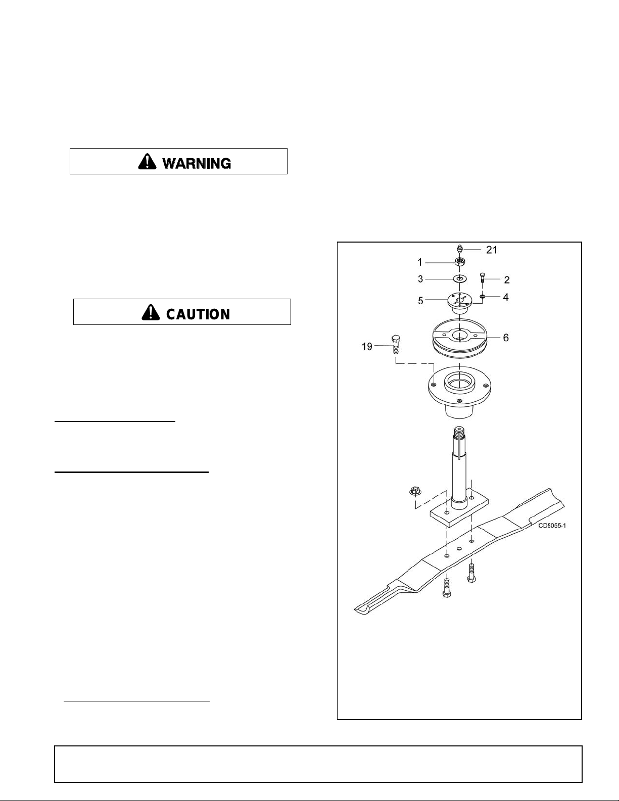
1. Remove cap screws (3) & lock nut (4), Figure 12.
2. Remove blade.
5WPMAN0862 (11/22/2010)
Your dealer can supply genuine replacement
blades. Substitute blades may not meet original
equipment specifications and may be dangerous.
NOTICE
■ Whe n installing blade, the lift of the blad e must
be toward the spindle blade housing as shown in
Figure 12.
1. Place c ap screws (3) thro ugh outer holes in blad e
and spindle shaft.
2. Make sure bla de cutting edge is p ositioned to lead
in a clockwise rotation, as viewed from top of
mower.
3. Place loc knuts (4) on screws and t orque to 84 lbsft.
Owner Service 23
Page 24

CLEANING
1. Spindle assembly
2. Blade
3. Screw, HHCS 1/2 NC x 1-1/2
GR5
4. Nut, flange lock 1/2 NC
Periodically or Before Extended Storage
● Clean large debris such as clumps of dirt, grass,
crop residue, etc. from machine.
● Remove the remainder usin g a low- pressur e water
spray.
1. Be careful when spraying near scratched or
torn safety decals or near edges of decals as
water spray can peel decal off surface.
2. Be careful when spraying near chipped or
scratched paint as water spray can lift paint.
3. If a pressure washer is used, follow the advic e
of the pressure washer manufacturer.
● Inspect machine and replace worn or damaged
parts.
● Sand down scratches and the edges of areas of
missing paint and co at with Woods spray paint of
matching color (purchase from your Woods
dealer).
● Replace any safety deca ls that are missing or no t
readable (supplied free by your Woods dealer).
See Safety Decals section for location drawing.
After Each Use
● Remove large debris su ch as clu mps of d ir t, gras s ,
crop residue, etc. from machine.
● Remove belt shields and clean out all accumulated
grass, dirt and other debris.
● Inspect machine and replace worn or damaged
parts.
● Replace any safety de cals that are missing or not
readable.
24 Owner Service
5WPMAN0862 (11/22/2010)
Page 25

TROUBLESHOOTING
MOWING CONDITIONS
PROBLEM POSSIBLE CAUSE SOLUTION
Grass cut higher in center of
swath than at edge
Grass cut lower in center of
swath than at edge
Streaking conditions in swath Conditions too wet for mowing Allow grass to dry before mowing.
Material discharges from mower
unevenly; bunches of material
along swath
Height of mower higher at front
than at rear
Loose Blade Check blade hardware.
Height of mower lower at front
than at rear
Loose Blade Check blade hardware.
Blades unable to cut that part of
grass pressed down by path of
tractor tires
Dull blades Sharpen or replace blades.
Loose Blade Check blade hardware.
Material too high and too much
material
Adjust mower height and attitude so that
mower rear and front are within 1/2 inch
of same height. See instructions on
page 15.
Adjust mower height and attitude so that
mower rear and front are within 1/2 inch
of same height. See instructions on
page 15.
Slow ground speed of tractor but keep
engine running at full PTO rpm.
Cutting lower will help.
Adjust tractor tire spacing if possible.
Reduce ground speed but maintain 540
rpm at tractor PTO, or make two passes
over material.
Raise mower for the first pass and lower
for the second and cut 90 degrees to first
pass.
Raise rear of mower high enough to
permit material discharge.
Grass wet Allow grass to dry before mowing. Slow
ground speed of tractor but keep engine
running at full PTO rpm.
5WPMAN0862 (11/22/2010)
Owner Service 25
Page 26

TROUBLESHOOTING
BELT COND I T IONS
PROBLEM POSSIBLE CAUSE SOLUTION
Belt slippage Mower overloading; material too
tall or heavy
Oil on belt from over-lubrication Be careful not to over-lubricate. Clean
Belt hung up or rubbing Check belt position in pulleys and
Frayed edges on belt cover Belt misaligned Re-align belt. Be sure belt does not
Pulley misaligned Inspect to ensure belt is running in
Reduce tractor ground speed but
maintain full PTO rpm.
Cut material twice, one high pass and
then mow at desired height.
Cut 90 degrees to first pass.
lubricant from belt and pulleys with
clean rag.
Replace oil-soaked belt.
idlers.
Check belt for free travel in pulleys.
Check under mower and around
blade spindle shaft for wire, rags, or
other foreign material.
Clean all material from under mower.
rub any other part while running.
center of backside idler.
Shim idler as necessary to align.
Belt rollover Pulley misaligned Re-align.
Damaged belt Replace belt*.
Foreign object in pulley groove Inspect all pulley grooves for rust,
paint, or weld spots and remove.
Worn pulley groove Replace pulley.
Damaged belt Rollover, high shock loads or
installation damaged
Belt breakage High shock loads Avoid abusive mowing.
Belt came off drive Check pulleys for foreign material in
* Check belt for damage by laying it flat on the floor. A belt that does not lie flat (has humps or twists, indicating broken
or stretched cords) must be replaced.
Replace belt*.
Avoid hitting the ground or large
obstructions.
grooves.
Avoid hitting solid objects or ground.
26 Owner Service
5WPMAN0862 (11/22/2010)
Page 27
DEALER SERVICE
WARNING
CAUTION
1. Nut, jam 7/8 NF
2. Screw, HHCS 1/4 NC x 1 GR5
3. Washer, lock .929 x 1.66
4. Washer, lock 1/4
5. Bushing, H 1 straight bore w/ke y
6. Sheave, H 1 BK
19. Screw, HHCS 1/2 NF x 1-1/4 GR5
21. Grease fitting
The information in this section is written for de aler service personnel. The repair described here requires
special skills and tools. If your shop is not properly
equipped or your mec han ic s a r e not pr ope rl y t ra ined i n
this type of repair, you may be time and money ahead
to replace complete assemblies.
Before working underneath, read manual
instructions, securely block up, and check stability.
Secure blocking prevents equipment from dropping due to hydraulic leak down, hydraul ic system
failure, or mechanical component failure.
Keep all persons away from operator control
area while performing adjustments, service, or
maintenance.
Always wear relatively tight and belted clothing
to avoid getting caught in moving parts. Wear
sturdy, rough-soled work shoes and protective
equipment for eyes, hair, hands, hearing, and head;
and respirator or filter mask where appropriate.
4. Disassemble split taper bushing (5) (located on top
of pulley) by removing the two bolts (2) and
washers (4).
5. Insert bol ts (2) into the threaded holes of bushing
flange.
6. Tighten bolts alternately to remove split taper
bushing.
7. Remove pulley (6).
8. Remove bolts (19) that attach spindle to mower
frame and remove spindle.
9. Remove grease fitting (21) from top of shaft.
BLOCKING METHOD
NOTE: SEE BLOCKING METHOD, PG. 19
BLADE SPINDLE SERVICE
Spindle Repair
Spindle repair requires special sk ills and tools. If your
shop is not properly equi pped or your mechanics are
not trained in this type of repair, you may be time and
money ahead to use a new spindle assembly.
For reference, the grease fitting is in the top of the spindle shaft.
®1
Permatex
is recommended as a sealant
3D Aviation Form-A-G asket or equivalent
Spindle Removal (Figure 13)
1. Remove blade from spindle.
2. Remove belt from pulleys.
3. Remove jam nut (1) and washer (3) from top of
spindle shaft.
1. Perm atex is a registered trademark of the Permatex
Corporation.
MAN0826 (8/31/2010)
Figure 13. Sheave and Blade Assembly
Dealer Service 27
Page 28
Spindle Disassembly
1. Grease fitting
2. Seal, 1.50 x 2.12 x .31
3. Sleeve, 1.14 x 1.50 x .55
4. Bearing cone
5. Bearing cup
6. Spindle housing
7. Shaft, blade spindle
1. Place spindle assembly in press and press shaft
down through housing.
2. Remove seals from housing.
3. Remove bearing cups from housing by placing a
punch in the slots provided and drivi ng them out.
Alternate punch positions from side to side. Take
care to prevent housing damage.
3. Place b ottom bearing cone into spindle with taper
positioned to mate with cup.
4. Identify the open side of the seal containing the
spring.
5. Apply a thin coat of Permatex to the area of
housing where seals seat.
6. Install botto m seal with spring up towa rd center of
housing.
Spindle Assembly (Figure 14)
■ Improper positioning of seals can cause seal
damage. An improperly installed seal will leak and
could cause bearing failure.
7. Place se al squarely on housing and se lect a piece
of pipe or tubing with an OD that will set on outside
edge of seal. A tubi ng with an O D that is too small
will bow seal cage.
8. Carefully press seal into housing to prevent
distortion to metal seal cage. Bottom seal should
seat firmly and squarely against machined
shoulder in housing.
9. Make sure seal lip did not roll under. Distortion to
seal cage or damage to seal lip will cause seal to
leak. Damaged seals must be replaced.
10. Insert shaft and bearing through bottom of housing.
11. Fill housing cavity with a medium grade grease.
12. Install top bearing on shaft to mate with top cone.
13. Apply a thin coat of Permatex to shaft ar ea where
sleeve will se at.
14. Install sleeve on shaft and press sleeve and
bearing into housing un til all free play is removed
and there is a very light drag on bearings (similar to
adjusting front wheel bearings on an automobile).
Check by spinning spindle. It should turn freely.
Figure 14. Spindle and Shaft Assembly
Bearing cones and cups are designed to work together.
It is important to position th em so bearing cone taper
mates with cup taper.
1. Lubricate new c ups with a light oil. Place them in
spindle housing so they will mate with bearing
cones. Cups and cones are a pr ess fit to minimi ze
wear.
2. Seat cups securely with a press or place a large
drift in the flat lip and drive th em into housing un til
cup seats against machined shoulder of housing.
28 Dealer Service
15. Be careful not to overtighten bearings. Proper
bearing adjustment is essential to good bearing
life.
16. If you overtighten bearings, hold spindle housing
and rap spindle shaft with a lead hammer.
17. Carefully pre ss top seal in with s pring up. Top seal
should be flush with or to within 1/16" above the
housing.
18. Rotate housing on spindle shaft, checking fo r free
movement.
19. Install grease fitting in spindle shaft.
MAN0826 (8/31/2010)
Page 29

Spindle Installation
19. Sheave, offset 13.25 PD
20. Gearbox stand
22. Shield, counter cone
42. Washer, flat standard 5/16
43. Screw, HHCS 8mm x 1.25P x 16mm
56. Nut, flanged lock 1/2 NC
59. Nut, flanged lock 5/8 NC
63. Screw, flanged hex head 5/8 NC x 1-3/4
NOTICE
■ Pulley installation sequence is very important
for bearing life. Follow the sequence exactly.
1. Install spindle through bottom of mower and secure
with four mounting bolts.
2. Install pulley and split taper bushing with integral
key on spindle shaft. Make sure bushing is in
contact with sleeve on spindle shaft.
3. Alternately tighten split taper bushing cap screws
to 12 lbs.-ft.
4. Install toothed lock washer and nut on spindle
shaft. Tighten nut until snug. Do not tighten this nut
with wrench. Bearing damage will result from overtightening. Bend up edge of lock washer.
GEARBOX SERVICE
Gearbox Removal from Mower (Figure 15)
1. Disconnect an d remove the r ear driveline fro m the
gearbox.
2. Remove vent plug and siphon gear lube from
housing through this opening.
3. Remove gearbox s tand (20) from mower deck by
removing four flanged lock nuts (56).
4. Remove four cap screws (43) and washers (42)
and remove shield (22) from gearbox.
5. Remove castle n ut a nd ha rd ware fr o m ou tput s ha ft
of gearbox.
6. Remove sheave (19) from gearbox.
7. Remove four bolts (63) and lock nuts (59) that
attach gearbox to gearbox stand and remove
gearbox.
Figure 15. Gearbox Stand Assembly
Gearbox Repair
Read this entire section before starting any repair.
Many steps are dependent on each other.
Fill gearbox with SAE 80W or 90W gear lube until it
runs out the side level plug.
Repair to this gearbox is limited to replacing bearings ,
seals, and gaskets. Replacing gears, shafts, and a
housing is not cost effective. It is more economical to
purchase a complete gearbox if repair to anything other
than replacement of bearings, seals or gaskets is
required.
Inspect gearbox for leakage and bad bearings.
Leakage is a very serious problem and must be cor-
rected immediately.
Bearing failure is indicated by excessive noise and
side-to-side or end play in gear shafts.
MAN0826 (8/31/2010)
Seal Replacement
Recommended sealant for ge arbox repair is Permatex
Aviation 3D Form-A-Gasket or equivalent.
Leakage can occur at th e vert ical or horiz ontal gask ets
and shaft seals.
Leakage at the horizontal gasket or seal can be
repaired without removing the gearbox from the cutter.
Dealer Service 29
Page 30

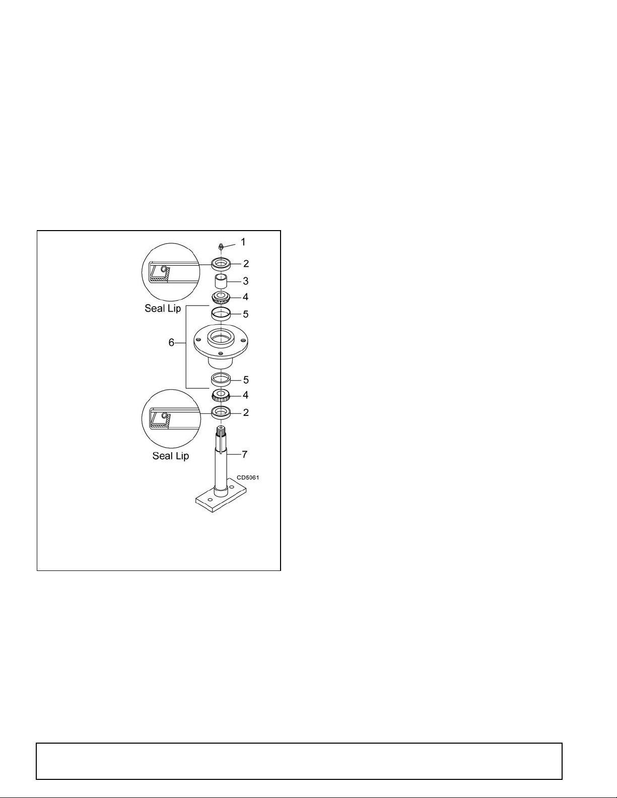
Seal Installation
1. Seal
2. Pipe or tube
3. Seal seat
4. Casting
NOTE: Pipe or tube must press at outer edge of seal.
Incorrect
Installation
1. Crown gear
2. Gearbox housing
3. Input shaft
4. Output shaft
5. Gear pinion
6. Bearing
7. Bearing
8. Protective flat washer
9. Cotter pin
10. Snap ring
11. Snap ring
12. Spacer
13. Shim kit
14. Castle nut
15. Castle nut M24 x 2
16. Shim kit
17. Flat washer
18. Oil seal (40 x 80 x 12)
19. Oil seal (35 x 72 x 10)
20. Cap
21. Snap ring
22. Top cover
23. Bolt M8 x 14mm
24. Breather plug
25. Cotter pin
26. Bearing
27. Ball bearing
NOTE: Proper seal installation is important. An improperly installed seal will leak.
1. Clean area in housing where seal outer diameter
(OD) seats. Apply a thin coat of Permatex.
2. Inspect area of shaft where seal seats. Remove
any burrs or nicks with an emery cloth.
3. Lubricate gear shaft and seal lips.
4. Place seal sq uarely on housing, spring-loaded lip
toward housing. Select a piece of pipe or tubing
with an OD that will sit on the outside edge of th e
seal but will clear th e housing. Tubing with an OD
that is too small will bow seal cage and ruin seal.
5. Carefully press seal into housing, avoiding
distortion to the metal seal cage.
Vertical Shaft Repair (Figure 17)
1. Disconnect and remove the driveline from the
gearbox.
30 Dealer Service
Figure 17. Gearbox Assembly
Figure 16. Seal Installation
2. Remov e vent plug (24) and siphon gear lube from
housing through this opening.
3. Remove gearbox stand from mower deck.
4. Remove gearbox and pulley from gearbox stand.
MAN0826 (8/31/2010)
Page 31

5. Remove vertical s haft seal (18). Rep lace with new
seal (see Seal Replacement, page 29).
14. Remove bearing (26) by using a punch and
hammer from the top, outside the housing.
Vertical seal should be recess ed in housing. Horizontal
seal should be pressed flush with outside of housing.
NOTE: Distortion to seal cage or damage to seal lip will
cause seal to leak.
6. Fill gearbox with SAE 80W or 90W gear lube until it
runs out the level plug.
7. Assemble gearbox and pulley to gearbox stand.
Attach gearbox stand to mower deck.
Horizontal Leak Repair (Figure 17)
1. Disconnect and remove the driveline from the
gearbox.
2. Remove vent pl ug (24) and si phon gear lube fr om
housing through this opening.
3. If the leak occurred at either end of horizontal shaft,
remove oil cap (20) and/or oil seal (19). Replace
with new one (refer to Seal Replacement, page
29).
4. Fill gearbox with SAE 80W or 90W gear lube until it
runs out the level plug.
Gearbox Disassembly (Figure 17)
1. Remove top cover (22) from housing. Turn gearbox
upside down and pour out remaining gear oil from
gearbox.
2. Remove oil cap (20) (to be replaced).
3. Remove snap ring (10) and shim (13) from input
shaft (3).
4. Support ge arbox in hand pr ess and push on input
shaft (3) to remove bearing (7) and spacer (11).
15. Support hous ing upside down (top cover surface)
and remove bearing (6) by using a punch and
hammer from the bottom side of the housing.
16. Inspect gears for broken teeth and wear. Some
wear is normal and will show on loaded side.
Forged gear surface s are rough wh en new. Check
that wear pattern is smooth.
17. Inspect vertical and horizontal shafts for grooves,
nicks, or bumps in the areas whe re the seals s eat.
Resurface any damage with emery cloth.
18. Inspect housing and caps for cracks or other
damage.
Gearbox Reassembly (Figure 17)
NOTE: Repair to this gearbox is limited to replacing
bearings, seals, and gask ets. Replacing gears, shafts,
and a housing is not cost effective. Purcha sing a complete gearbox is more economical.
1. Clean housing, paying specific attention to areas
where gaskets will be installed.
2. Wash housing and all components thoroughly.
Select a clean area for gearbox assembly. Replace
all seals, bearings, and gask ets. All parts must be
clean and lightly oiled before reassembling.
3. Insert output bearings (6 & 26) in the housing,
using a round tube of the c orrect diameter and a
hand press.
4. Slide output shaft (4) through both bearings (6 &
26) until it rests against bearing (6).
5. Slide shim (16) over output shaft (4 ).
5. Remove gear (1) from inside housing.
6. Remove oil seal (19) from front of housing (to be
replaced).
7. Remove snap rin g (10) and shim (1 3) from front of
housing (2).
8. Remove input bearing (7) by using a punch and
hammer from outside of housing.
9. Support housing in vise in a horizontal position.
10. The castle nut (15) and cotter pin (25) ar e already
removed with the drive she ave. Remove the snap
ring (21), washer (8), and seal (18).
11. Remove cotter pin (9), castle nut (14), a nd wash er
(8) from output shaft (4).
12. Remove output shaft (4) by using a punch and
hammer and tap on top to drive down.
13. Remove gear (5) and shim (16) from inside
housing.
MAN0826 (8/31/2010)
6. Press gear (5) onto output shaft (4) and secure
with washer (17), castle nut (14), and cotter pin (9).
7. Appl y grease to lo wer seal l ips (18) an d pres s seal
over output shaft (4), using a tube of the correct
diameter. Be sure not to damage the seal lip. Press
in housing so that seal is recessed.
8. Insert protective washer (8) by hand. I nstall sna p
ring (21) and posi tion it together with dua l lip seal
(18) by pressing it into position. Verify that snap
ring is seated correctly.
9. Press bearing (7) into the hous ing, using a round
tube of the correct diameter and a hand press.
Secure with shim (13) and snap ring (10).
10. Secure snap ring (11) on input shaft (3) if not
already secure.
11. Place gear (1) through top of housing and align
gear (1) and gear (5) so that gear teeth are a
match.
Dealer Service 31
Page 32

12. While holding gear (1) in place, slide input shaft (3)
1. Shim
2. Idler arm
3. Idler pulley
4. Drive sheave
5. Castle nut & cotter
pin
6. Gearbox stand
1. Yoke
2. Cup and bearing
3. Snap ring
4. Journal cross
through gear (1) and bearing (7). Al ign splines on
shaft (3) and gear (1).
13. Slide spacer (12) over input shaft (3) and press
bearing onto input shaft (3), u sing a round tube of
the correct diameter and a hand press.
14. Slide shim (13) over input shaft (3) and secure with
snap ring (10).
15. Check input shaft end float by moving the input
shaft (3) by hand. If end flo at i s hig her th an 0.01 2” ,
insert shim between input shaft (3) and rear
bearing (7). Repeat until end float is less than
0.012”. Check rotational torque by hand. The
torque should be less than 2.2 lbs-inch.
16. Check that the gear backlash is between 0.006”
and 0.016”. You should not have to adjust the
backlash.
17. Press in input oil seal (19), using tube of correct
diameter. Be careful not to damage seal lip.
18. Press oil cap (20) on to cov er the rear of ho using,
using a tube of the correct diameter.
5. Replace driveline shield. Attach driveline to
gearbox.
Figure 18. Drive Sheave Installation
UNIVERSAL JOINT REPAIR
19. Check gearbox housing for leaks by plugging all
holes except one. Appl y 4 psi compressed a ir and
immerse the gearbox i n water to verify that there
are no leaks.
20. Remove gearbox from water and dry off with
compressed air. Add SAE 80W or 90W EP oi l until
it runs out of side level hole. Tighten all plugs.
Gearbox Installation
NOTE: Gearbox is heavy: do not attempt to move with-
out mechanical assistance.
1. Set gearbox on gearbox stand and fasten with
bolts and nuts. Torque bolts to 175 lbs-ft.
2. Attach drive she ave to output shaft. Secure usin g
castle nut and hardware previously removed.
3. Attach gearbox stand to mower using four flange d
lock nuts.
DRIVE SHEAVE INSTALLATION (FIGURE 18)
1. When gear stand i s installed on mower, dimension
A (from the top of the mower deck to the center line
of the drive pulley) must be 2-7/16" (±1/32"). This is
a critical dimensio n and m ust be ca refully adjus ted
for proper belt life. Add or subtr act shim washers
under idler pulley to align with drive pulley.
2. Tighten gear stand hardware.
3. Fill gearbox half full with SAE 90W gear lube.
4. Check level after waiting five minutes to permit
lube to work through bearings. Add lube, if
necessary, until gearbox is half full.
Figure 19 . U-Joint Exploded View
U-Joint Disassembly
1. Remove external snap rings from yokes in four
locations as shown in Figure 20.
Figure 20
32 Dealer Service
MAN0826 (8/31/2010)
Page 33

2. With snap rings removed, support drive in vise,
hold yoke in hand and tap on yoke to drive c up up
out of yoke. See Figure 21.
Figure 21
3. Clamp cup in vise as shown in Figure 2 2 and tap
on yoke to completely remove cup from yoke.
Repeat Step 2 and Step 3 for opposite cup.
U-Joint Assembly
1. Place seals securely on bearing cups. Insert cup
into yoke from outside and press in with hand
pressure as far as possible. Insert journal cross
into bearing cup with grease fitting away from
shaft. Be careful not to disturb needle bearings.
Insert another bearing cup directly across from first
cup and press in as far as possible with hand
pressure.
2. Trap cups in vise and apply pressure. Be sure
journal cross is started into bearin gs and continue
pressure with vise, squeezing in as far as possible.
Tapping the yoke will help.
3. Seat cups by placing a drift or socket (slightly
smaller than the cup) on cup and rap with a
hammer. See Figure 24. Install snap ring and
repeat on opposite cup.
4. Repeat Step 1 and Step 2 to install remaining cups
in remaining yoke.
5. Move both yokes in all directions to check for free
movement. If movement is restricted, rap on yokes
sharply with a hammer to relieve any tension.
Repeat until both yokes move in all directions
without restriction.
Figure 22
4. Place universal cross is vise as shown in Figure 23
and tap on yoke to remove cup. Repeat Step 3 for
final removal. Drive remaining cup ou t with a drift
and hammer.
Figure 23
MAN0826 (8/31/2010)
Figure 24
Dealer Service 33
Page 34

ASSEMBLY INSTRUCTIONS
WARNING
CAUTION
Remove hardware
Remove 5/8 Lock nut
WARNING
DEALER SET-UP INSTRUCTIONS
The mower is shipped mostl y assembled but requires
dealer set-up. The Frontier dealer should deliver the
mower to the owner comp letely as sembled , lubricated ,
and adjusted for normal conditions.
Recommended torque va lues f or hardw are are l ocate d
on page 61.
Complete check lists on page 38 when assembly is
complete.
Keep hands and body away from pressurized
lines. Use paper or cardboard, not hands or other
body parts to check for leaks. Wear safety goggles.
Hydraulic fluid under pressure can easily penetrate
skin and will cause serious injury or death.
Make sure that all operating and service personnel know that if hyd raulic fluid pe netrates s kin, it
must be surgically removed as soon as possible by
a doctor familiar with this form of injury or gangrene, serious injury, or death will result. CONTACT A PHYSICIAN IMMEDIATELY IF FLUID
ENTERS SKIN OR EYES. DO NOT DELAY.
Make sure spring-acti vated locking pin or collar
slides freely and is seated firmly in tractor PTO
spline groove.
Always wear relatively tight and belted clothing
to avoid getting caught in moving parts. Wear
sturdy, rough-soled work shoes and protective
equipment for eyes, hair, hands, hearing, and head;
and respirator or filter mask where appropriate.
Figure 25. Remove Shipping Hardware
5. Gently lower deck until the deck is supported by
the lift chains.
6. Remove 5 /8 lock nuts and remove shipping st rap
from between right and left decks, Figure 26.
Figure 26. Remove Shipping Strap (Right Wing)
ATTACH HYDRAULIC HOSES
REMOVE SHIPPING STRAPS
1. Remove front drive from between wing frames.
2. Attach to stub shaft (see trailer assembly).
3. Lift rear deck to take tension off rear lift chains.
4. Remove 3/8 bolts, washers, and nuts from both
rear lift chains. Se e Fi gur e 25. T his har dwa re is for
factory shipping purposes only and can be
discarded.
34 Assembly
Air in hydraulic systems ca n cau se er ratic o peration and allows loads or equipment components
to drop unexpectedly. When connecting equipment
or hoses or performing any hydraulic maintenance,
purge any air in hydraulic system by operating all
hydraulic functions several times. Do this before
putting into service or allowing anyone to
approach the equipment.
5WPMAN0862 (11/22/2010)
Page 35

Attach the mower hydraulic hose to the tractor port.
1. Light, 4 Pin Right
2. Light, 4 Pin Left
3. Light Bracket
4. Blank .16 x 4.00 x 4.00
5. Wire Harness
6. 3/8 NC x 3-1/2 HHCS
7. 3/8 NC Flange Lock Nut
8.1/4 NC x 1 HHCS
9. 1/4 NC Lock Nut
10. #10 x 1/2 Tapping
Screw
11. 34” Cable Tie
1. Rear Roller
2. Rear Roller Bracket
3. 1/2 NC x 5-1/2 HHCS
4. 1/2 Flat Washer
5. 1/2 NC Flange Lock Nut
6. 3/8 NC x 1 Carriage Bolt
7. 3/8 NC Flange Lock Nut
Hydraulic quick coupler is not supplied.
NOTE: The mower hydraulic syst em sh oul d have bee n
filled at the factory. Always assume it is empty. Fully
purge air and fill the hydraulic system by raising and
lowering wings se veral tim es while h ooked to a tractor
hydraulic supply. Keep all personnel away while raising
and lowering.
OPTIONAL EQUIPMENT
Light Kit Installation
7. Extra slack in the light wires should be located near
the wireing harness. Make sure wires cannot
become entangled in driveline or hydraulic
cylinder. Secure wires to frame tubes above
cylinder and lock with cable ties.
Rear Roller Kit Installation
Figure 27. Light Kit I nstallation
1. Install wire harness (5 ) to bracket on trailer frame
using #10 screws (10).
2. Route wires as shown. Be su re wire labeled “Left”
is routed to the le ft side of the unit. Wrap excess
wire around rear deck frame tubes as shown.
3. Clamp bracke ts (3) to re ar deck frame tub es usin g
blanks (4), 3/8 bolts (6) and nuts (7).
4. Secure left and right lamp (1 & 2) to brackets using
1/4 bolts (8) and nuts (9).
5. Connect light to wiring harness.
6. Pull any slack out of main wire and install cable ties
(11) to rear hydraulic hose and trailer frame.
5WPMAN0862 (11/22/2010)
Figure 28. Rear Roller Kit Installation
Assembly 35
Page 36

Front Roller Kit Installation
-- Roller Kit, Front Complete
2. 1/2 NC Flange Lock Nut
3. 1/2 NC x 9 HHCS GR5
4. Flat Washer, 1/2 SAE
5. Carriage Bolt, 3/8 NC x 1
6. Flanged Whiz Nut, 3/8 NC
7. Spacer, .75 x 6.62
8. Bracket, Front Roller
9. Roller, 4 x 7.37
10.Bearing
-- Roller Kit, Front Complete
2. 1/2 NC Flange Lock Nut
3. 1/2 NC x 9 HHCS GR5
4. Flat Washer, 1/2 SAE
5. Carriage Bolt, 3/8 NC x 1
6. Flanged Whiz Nut, 3/8 NC
7. Spacer, .75 x 6.62
8. Bracket, Front Roller Right
9. Bracket, Front Roller Left
10. Roller, 4 x 7.37
11. Bearing
Figure 29 FM1012 Rear Deck and FM1015 and FM1017 Front Roller Kit Installation
Figure 30 FM1012 Wing Deck Front Roller Kit Installation
36 Assembly
5WPMAN0862 (11/22/2010)
Page 37

Hydraulic Latch Release Installation
1. Release Base
2. Slide Channel
3. 3 x 8 Hydraulic Cylinder
4. Bushing
5. Elbow
6. Hose, 108”
7. Pin 1 x 4.08
8. Cotter Pin
9. Flat Washer, 1”
10. 3/8 NC x 1 HHCS GR5
11. 3/8 NC Flange Lock Nut
Figure 31. Hydraulic Latch Release Installation
1. Remove four 1/3 NC x 2 hex hea d cap screw s and
1/2” flat washers from top of shield on trailer.
2. Attach item 1 on top of shield using hardware
previously removed.
3. Attach item 2 to win g release leve r using items 1 0
and 11.
4. Attach base end of cylinder (3) to item 1 using
items 7, 8, and 9. Cylinder ports should be pointing
upward.
5. Attach r od end of cylin der (3) to ite m 2 us ing it ems
7, 8, and 9.
6. Install redu cers (4), elb ows (5), and ho ses to base
of cylinder.
5WPMAN0862 (11/22/2010)
Assembly 37
Page 38

DEALER CHECK LISTS
PRE-DELIVERY CHECK LIST
(DEALER’S RESPONSIBILITY)
Inspect the equipment thoroughly after assembly to
ensure it is se t up properly before delivering it to the
customer.
The following check lists are a reminder of points to
inspect. Check o ff each item as it is found satisfac tory
or after proper adjustment is made.
___ Check that all sa fety decals are installed and in
good condition. Replace if damaged.
___ Check that shields and guards are properly
installed and in good condi tion. Replace if damaged.
___ Check all bolts to be sure they are properly
torqued.
___ Check that all cotter pins and safety pins are
properly installed. Replace if damaged.
___ Check that blades have been properly installed.
___ Check mower attitude and belt alignment
___ Check and grease all lub rication points as ident i-
fied in lubrication information on page 20.
___ Check the level of gearbo x fluids before de livery.
Service, if required , as spe ci fie d in the l ubr ica tion
information on page 20.
DELIVERY CHECK
(DEALER’S RESPONSIBILITY)
___ Show customer how to make adjustments and
select proper PTO speed.
___ Show customer how to make sure driveline is
properly installed and tha t spring-activated locking pin or collar slides freely and is seated in
groove on tractor PTO shaft.
___ Show customer how to dete rmine the turning lim-
its of the CV PTO driveline.
___ Show customer the safe, proper procedures to be
used when mounting, dismounting, and storing
equipment.
___ Make customer aware of optional equipment
available so that customer can make proper
choices as required.
___ Instruct customer how to lubricate and explain
importance of lubrication.
___ Point out the safety decals. Explain their meaning
and the need to keep them in plac e and in good
condition. Emphasize the increased safety hazards when instructions are not followed.
___ Present Operator's Ma nual and r equest that cus-
tomer and all operators read it befor e operating
equipment. Point out the manual safety rules,
explain their meanings and emphasize the
increased safet y hazards that exist when safety
rules are not followed.
___ Explain to customer the potential crushing haz-
ards of going underneath raised equipment.
Instruct that before go ing underneath to disconnect the driveline, securely block up all corners
with jackstands and to follow all instructions in
BLOCKING METHOD, page 19 o f the operator ’s
manual. Explain that blocki ng up prevents equipment dropping from hydrau lic l eak down, hy draulic system failures or mechanical component
failures.
38 Dealer Check List
___ Point out all guards and shields. Explain their
importance and the safety hazards that exist
when not kept in place and in good condition.
5WPMAN0862 (11/22/2010)
Page 39

PARTS INDEX
Rear Discharge Grooming Mowers:
FM1012, FM1015, & FM1017
COMMON PARTS
MAIN FRAME ASSEMBLY. . . . . . . . . . . . . . . . . . . . . . . . . . . . . . . . . . . . . . . . . . . 40 - 41
TRAILER ASSEMBLY . . . . . . . . . . . . . . . . . . . . . . . . . . . . . . . . . . . . . . . . . . . . . . 42 - 43
WING FRAME ASSEMBLY . . . . . . . . . . . . . . . . . . . . . . . . . . . . . . . . . . . . . . . . . . . . . . 44
CENTER & WING DECK ASSEMBLY . . . . . . . . . . . . . . . . . . . . . . . . . . . . . . . . . . . . . . 45
FM1012 WING DECK ASSEMBLY . . . . . . . . . . . . . . . . . . . . . . . . . . . . . . . . . . . . . . . . 46
HEIGHT ADJUSTMENT POST . . . . . . . . . . . . . . . . . . . . . . . . . . . . . . . . . . . . . . . . . . . 47
HUB & AXLE ASSEMBLY . . . . . . . . . . . . . . . . . . . . . . . . . . . . . . . . . . . . . . . . . . . . . . . 47
CASTER ARM & WHEEL. . . . . . . . . . . . . . . . . . . . . . . . . . . . . . . . . . . . . . . . . . . . 48 - 49
WING GEARBOX ASSEMBLY. . . . . . . . . . . . . . . . . . . . . . . . . . . . . . . . . . . . . . . . . . . . 50
BLADE AND SPINDLE ASSEMBLY . . . . . . . . . . . . . . . . . . . . . . . . . . . . . . . . . . . . . . . 51
FM1012 REAR DECK &
FM1015 & FM1017 FRONT ROLLER ASSEMBLY (OPTIONAL) . . . . . . . . . . . . . . . . . 52
FM1017 WING DECK FRONT ROLLER ASSEMBLY (OPTIONAL) . . . . . . . . . . . . . . . 52
REAR ROLLER ASSEMBLY (OPTIONAL) . . . . . . . . . . . . . . . . . . . . . . . . . . . . . . . . . . 53
REAR CHAIN SHIELDING ASSEMBLY. . . . . . . . . . . . . . . . . . . . . . . . . . . . . . . . . . . . . 53
REAR & WING DRIVES. . . . . . . . . . . . . . . . . . . . . . . . . . . . . . . . . . . . . . . . . . . . . 54 - 55
CV DRIVE ASSEMBLY . . . . . . . . . . . . . . . . . . . . . . . . . . . . . . . . . . . . . . . . . . . . . . . . . 56
JACKSHAFT DRIVE ASSEMBLY . . . . . . . . . . . . . . . . . . . . . . . . . . . . . . . . . . . . . . . . . 57
HYDRAULIC CYLINDER . . . . . . . . . . . . . . . . . . . . . . . . . . . . . . . . . . . . . . . . . . . . . . . . 58
LIGHT KIT (OPTIONAL). . . . . . . . . . . . . . . . . . . . . . . . . . . . . . . . . . . . . . . . . . . . . . . . . 59
HYDRAULIC LATCH RELEASE KIT (OPTIONAL) . . . . . . . . . . . . . . . . . . . . . . . . . . . . 60
(Rev. 8/6/2012)
5WPMAN0862 (11/22/2010)
Parts 39
Page 40

FM1012, FM1015 & FM1017 MAIN FRAME ASSEMBLY
40 Parts
5WPMAN0862 (11/22/2010)
Page 41

FM1012, FM1015 & FM1017 MAIN FRAME ASSEMBLY
REF PART QTY DESCRIPTION
1 ----- 1 Trailer assembly (see page 42)
2 ----- 1 Right wing assembly (see 44)
3 ----- 1 Left wing assembly (see page 44)
4 ----- 1 Right deck assembly FM1012 (see
page 46) -or-
4 ----- 1 Right deck assembly FM1015,
FM1012 (see page 45)
5 ----- 1 Left deck assembly FM1012 (see
page 46) -or-
5 ----- 1 Left deck assembl y FM1015, FM1017
(see page 45)
6 5WP40805 1 Rear wing assembl y
7 ----- 1 Rear deck assembly (see page 45)
8 5WP1023226 2 Drive, Cmpl 40, 21.3 x 32.3 FM1012
(see page 54) -or8 5WP1023227 2 Drive, Cmpl 40, 25.6 x 40.9 FM1015
(see page 54) -or8 5WP1023228 2 Drive, Cmpl 40, 28.3 x 46.4 FM1017
(see page 54)
9 5WP1023225 1 Drive, Cmpl 40, 26.9 x 43.5 (see p age
54)
10 ----- 6 Rotating caster & arm (see page 48)
11 ----- 4 Non-rotating caster & arm (see page
48)
12 ----- 2 Height adjustment post and arm (see
page 47)
13 5WP38001 4 Pin, Wing hinge
14 5WP58984 2 Pin, Rear wing hinge
15 5WP1791 6 .63 x 1.00 x .56 HT Sleeve
16 5WP44638 2 1/4 Chain - 16 link
17 5WP62484 1 SMV Socket
18 5WP1004251 1 SMV Bracket
19 5WP24611 1 SMV Emblem
20 5WP38296 1 Rope, .25 x 95.0
21 5WP38295 3 Rope clamp
22 5WP38257 3 S-Hook .25 x 2.25
REF PART QTY DESCRIPTION
23 5WP38294 1 Rope, .25 x 46.0
24 5WP1031166 2 Hydraulic cylinder 3 x 10 (see page
58)
25 5WP29474 1 Hydraulic cylinder 3 x 8 (see page
58)
26 5WP1631 2 1 x 3.63 Headless pin
27 5WP8346 4 1 x 4.58 Headless pin
28 5WP1006400 1 Bulkhead fitting, 9/16 JICM x 1/4
NPTM
29 5WP1006401 1 Cross, 9/16 JICM x 1/4 NPTF
30 5WP1006402 2 Hose, 33 x 9/16 JICF x 9/16 JICM
31 5WP1006403 1 Hose, 48 x 9/16 JICF x 9/16 JICM
32 5WP1006404 1 Hose, 108 x 9/16 JICF x 1/4 NPTM
33 5WP1006405 3 Elbow, 9/ 16 JICF x 1/2 NP TM 90o w/
3/32 Restricter
34 5WP40908 1 Complete decal set
40 * Pin, Safety 3/16
41 * 1/4 NC x 1/2 Round head screw
42 * 1 /4 NC Hex nut
43 * Pin, Cotter 1/4 x 1-3/4
44 * 5/16 NC x 1/2 Carriage bolt
45 * 5/16 NC Flange lock nut
46 * 1/2 NC x 1-3/4 HHCS GR5
47 * 1/2 NC x 2 HHCS FT GR5
48 * 1/2 NC x 3-1/2 GR5
49 * 1/2 Flat washer
50 * 1/2 NC Flange lock nut
51 * 5/8 NC x 2-1/2 HHCS GR5
52 * 5/8 NC Flange lock nut
53 * 1 Standard flat washer
HHCS
Hex Head Cap Screw
* Standard Hardware, Obtain Locally
(Rev. 10/30/2012)
5WPMAN0862 (11/22/2010)
Parts 41
Page 42
FM1012, FM1015 & FM1017 TRAILER ASSEMBLY
42 Parts
5WPMAN0862 (11/22/2010)
Page 43

FM1012, FM1015 & FM1017 TRAILER ASSEMBLY
REF PART QTY DESCRIPTION
1 ----- 1 Trailer frame
2 5WP1009501 1 Hitch, Cat 1 -or2 5WP1009502 1 Hitch, Cat 2 -or2 5WP1003635 1 Hitch, rigid clevis (optional)
3 5WP1006689 2 Hitch adjustment link
4 5WP44639 2 .76 x 1.00 x 4.12 Sleeve
5 5WP40804 1 Lock, rear deck
6 5WP40880 1 Release lever, rear deck lock
7 5WP40879 2 Lock, wing deck
8 5WP40938 1 Release lever, wing deck lock
9 5WP19201 1 H-Frame
10 5WP44641 2 .78 x 1.00 x .69 HT Sleeve
11 5WP31464 2 .38 x .63 x .34 Sleeve
12 5WP23790 1 Parking jack
13 5WP21957 3 Spring, compression .58 x .08 x 2.4 40
14 5WP484 2 .63 x 1.00 x .44 HT Sleeve
15 5WP3502 1 Ball bearing
16 ----- 1 Bearing housing (not serviced)
17 5WP1251 1 Bearing holder w/bearing (includes 15,
16, 33, 41)
18 5WP44637 1 Shield, front drive
19 ----- 1 Drive, Yk & Shft Ntel 2400 x 26.4 (see
page 57)
20 5WP1021100 1 Drive, Cmpl CV 35R, 35.0 x 47.6 (see
page 56)
21 5WP19407 1 Safety chain
22 5WP71444 2 Rubber bumper
23 5WP38264 1 Pin, lynch chain & co tter
24 5WP40933 1 Gearbox, 4-Way Splitter
-- 5WP58815 2 Seal, Thru Shaft 4-Way Grbx
-- 5WP58816 2 Seal, Wing Shaft 4-Way Grbx
-- 5WP58817 6 Bearing, Cup & Cone 4-Way Grbx
-- 5WP1011780 1 Vent plug & washer
24C 5WP40933C 1 Gearbox, 4-Way Splitter (Comer)
-- 5WP57462 4 Bearing, Cup & Cone
-- 5WP20890 2 Bearing, Ball
-- 5WP57463 4 Oil Seal
-- 5WP57076 1 Vent plug
25 5WP62626 4 .76 x 1.00 x 1.00 Sleeve
26 5WP44636 1 Shield, Gearbox 4-Way
27 5WP1001020 2 Wheel Hub & Axle (see page 47)
REF PART QTY DESCRIPTION
28 5WP38298G 2 Wheel & Tire, 20.5 x 8.00 x 10 Gray
-- 5WP38475G Whe el Rim, 5-Bolt 8.00 x 10 Gray
29 5WP3443 1 Hydraulic hose holder
30 5WP103177 6 1 Wing stop mount bracket
31 5WP1031780 1 Wing Stop FM1012 - or 31 5WP1031781 1 Wing stop FM1015, FM1017
32 5WP11606 1 Pin, Spi rol 3/8 x 1-1/2
33 5WP12128 1 .06 x 72 MM Retaining ring
40 * 1/4-28 Grease fitting
41 * 1/4-28 90° Grease fitting
42 * 5/16 NC Flange lock nut
43 * 3/8 NC x 1 HHCS GR5
44 * 3/8 NC x 1-1/4 HHCS GR5
45 * 3/8 NC x 3-1/2 HHCS GR5
46 * 3/8 Lock washer
47 * 3/8 Standard flat washer
48 * 3/8 NC Flange lock nut
49 * 3 /8 NC Lock nu t
50 * 1/2 NC x 1-1/4 HHCS GR5
51 * 1/2 NC x 1-3/4 HHCS GR5
52 * 1/2 NC x 2 HHCS GR5
53 * 1/2 NC x 3 HHCS GR5
54 * 1/2 NF x 1-1/8 Wheel bolt
55 * 1/2 NC x 5-1/4 HHCS GR5
56 * 1/2 Standard flat washer
57 1/2 Flat washer, extra thick hardened
58 * 1/2 NC Flange lock nut
59 * 5/8 NC x 2 HHCS GR5
60 * 5/8 NC x 5 HHCS GR5
61 * 5/8 NC x 7 HHCS GR5
62 * 5/8 NC x 7-1/2 HHCS GR5
63 5WP34467 .63 x 2.00 x .38 Flat washer
64 5WP10635 .63 x 1.75 x 14 Ga Cupped washer
65 * 5 /8 NC Lock nu t
66 * 3/4 x 2-1/4 HHCS GR5
67 5WP28873 3/4 x 1-1/2 x 1/4 Flat washer
68 * 3 /4 NC Lock nu t
69 5WP44640 1.04 x 2.25 x .17 Cupped washer
HHCS
Hex Head Cap Screw
* Standard Hardware, Obtain Locally
(Rev. 8/5/2011)
5WPMAN0862 (11/22/2010)
Parts 43
Page 44

FM1012, FM1015 & FM1017 WING FRAME
REF QTY FM1012 FM1015 FM1017 DESCRIPTION
1 1 5WP1032460 5WP1032480 5WP1032490 Frame, right wing
2 1 5WP1032461 5WP1032481 5WP1032491 Frame, left wing
3 2 5WP1032451 5WP1032455 5WP1032455 Link, wing deck lift
4 2 5WP40895 5WP40895 5WP40887 Trunnion, front deck
5 2 5WP40896 5WP40896 5WP40888 Trunnion, rear deck
6 1 5WP1003828 5WP1003828 5WP1003828 Manual tube
7 2 5WP71444 5WP71444 5WP71444 Rubber bumber
8 2 5WP38264 5WP38264 5WP38264 Pin, lynch chain & cotter
9 2 5WP58980 5WP58980 5WP58980 Pin, wing deck link
10 4 5WP58982 5WP58982 5WP58982 Pin, deck link trunnion
11 * Pin, safety 3/16
12 * 1/4-28 Grease fitting
13 * 5/16 NC x 1 HHCS GR5
14 * 5/16 SAE Flat washer
15 * 5/16 NC Flange lock nut
HHCS Hex Head
Screw
* Standard Hardware,
obtain locally
Cap
44 Parts
5WPMAN0862 (11/22/2010)
Page 45
FM1012 CENTER DECK
FM1015 & FM1017 CENTER & WING DECK ASSEMBLY
REF PART QTY DESCRIPTION
1 5WP1031795 1 5’ Mower Deck (FM1012 Rear, FM1015 Wings)
1 5WP1031796 1 6’ Mower Deck (FM1015 Rear, FM1017 All)
2 5WP1001244 1 V-Belt W99 (FM1012 Rear, FM1015 Wings)
2 5WP18879 1 V-Belt W112 (FM1015 Rear, FM1017 All)
3 ----------- 3 CW Spindle assembly (See page 51)
4 5WP1014417 2 Belt Shield, 5’ Deck (FM1012 Rear, FM1015
Wings)
4 5WP1014418 2 Belt Shield, 6’ Deck (FM1015 Rear, FM1017
All)
5 5WP53534 1 Gearbox Stand
6 5WP1002499 1 Gearbox, 1:1.92 (See page 50)
7 5WP1014410 1 Sheave, Offset 13.25 P.D.
8 5WP29792 1 Key, HT 1/4 x 1/4 x 1-1/4
9 5WP53567 1 Guide, Belt 8 Ga Formed
10 5WP64555 1 Idler, Flat 5.5 Dia.
11 5WP58989 1 Idler Arm Assembly
12 5WP53595 1 Idler, Flat 5.0 Dia.
13 5WP67131 1 Spring, Ext .177 x 1.22 x 9.88
14 5WP35193 2 Bearing, Ball
REF PART QTY DESCRIPTION
15 5WP1002048 1 Clutch Shield
16 5WP35141 2 Ring, Retaining Int .062 x 1.56
20 * Pin, Cotter 3/16 x 1-1/2
21 * Washer, Flat 5/16
22 * Lock Washer, 5/16
23 * M8 x 1.25P x 20 MM HHCS
24 * 3/8 NC x 1 Hex Flange Serrated
25 5WP1008011 3/8 NC SQ Nut with Retainer
26 * Screw, HHCS 1/2 NF x 1-1/4 GR5
27 * 1/2 NC x 2-1/2 HHCS GR5
28 5WP24537 Washer, Flat .50 x 1.38 x .38
29 5WP31983 Shim, .50 x .88 x 18GA
30 * Flange Lock Nut 1/2 NC
31 * 5/8 NC x 1-3/4 HHCS GR5
32 5WP1517 Flat Washer, .63 x 1.38 x 7 GA
33 * 5/8 Flange Lock Nut
34 5WP302178 5/8 NF Castle Nut
HHCS
Hex Head Cap Screw
* Standard Hardware, Obtain Locally
5WPMAN0862 (11/22/2010)
Parts 45
Page 46

FM1012 WING DECK ASSEMBLY
REF PART QTY DESCRIPTION
1 5WP1031800 1 4’ Mower Deck, RH -or-
1 5WP1031801 1 4’ Mower Deck, LH
2 5WP40930 1 V-Belt, W80
3 ---------- 3 CW Spindle assembly (See
page 56)
4 5WP1031783 1 Inner Belt Shield
5 5WP1031784 1 Outer Belt Shield, RH -or-
5 5WP1031785 1 Outer Belt Shield, LH
6 5WP58294 1 Gearbox Stand, RH -or-
6 5WP58295 1 Gearbox Stand, LH
7 5WP1002499 1 Gearbox, 1:1.92 (See page 50)
8 5WP1014410 1 Sheave, Offset 13.25 PD
9 5WP29792 1 Key, 1/4 x 1/4 x 1-1/4 HT
10 5WP1027525 2 Belt Guide
11 5WP57939 1 Idler Arm Assembly
12 5WP53595 1 Idler, Flat 5.0 Dia
13 5WP67131 1 Spring, Ext .177 x 1.22 x 9.88
14 5WP35193 2 Bearing, Ball
15 5WP1002048 1 Clutch Shield
REF PART QTY DESCRIPTION
16 5WP35141 2 Ring, Retaining Int .062 x 1.56
20 * Pin, Cotter 3/16 x 1-1/2
21 * Washer, Flat 5/16 SAE
22 * Lock Washer, 5/16
23 * M8 x 1.25P x 20MM HHCS
24 * Screw 3/8NC X 1 Hex Flange Ser-
rated
25 5WP1008011 Nut, SQ 3/8 NC With Retainer
26 * Screw, HHCS 1/2 NF x 1-1/4 GR5
27 * HHCS, 1/2 NC x 2-1/2 GR5
28 5WP24537 Washer, Flat .2 x 1.38 x .375
29 5WP31983 Shim, .50 x .88 x 18GA
30 * Nut, Flanged Lock 1/2 NC
31 * Screw, Flngd Hex Head 5/8 NC x 1-
3/4
33 * Nut, Flanged Lock 5/8 NC
34 5WP302178 Nut, Castle 5/8 NF
HHCS
Hex Head Cap Screw
* Standard Hardware, Obtain Locally
46 Parts
5WPMAN0862 (11/22/2010)
Page 47
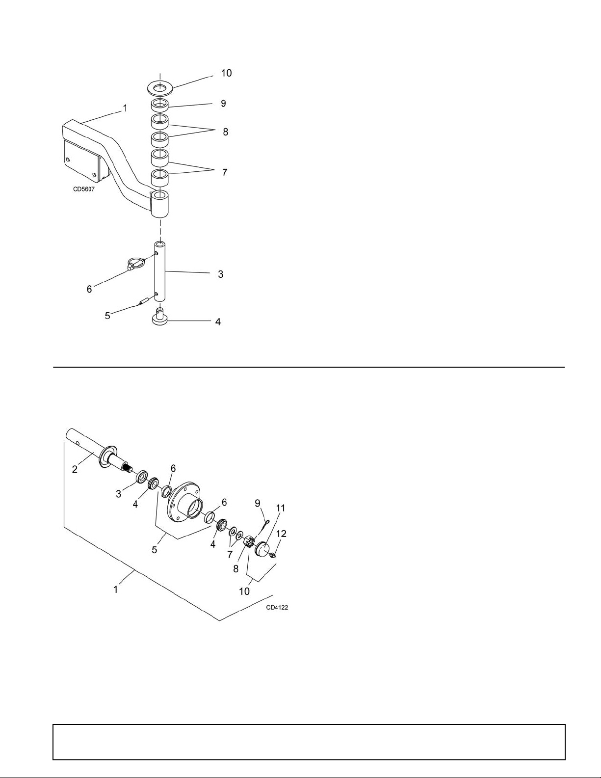
HEIGHT ADUSTMENT POST
REF PART QTY DESCRIPTION
1 5WP58993 1 Caster Arm, RH (FM1012) - or -
1 5WP1031754 1 Caster Arm, RH (FM1015, FM1017)
2 5WP58994 1 Caster Arm, LH (FM1012) - or -
2 5WP1031755 1 Caster Arm, LH (FM1015, FM1017)
3 5WP58998 1 Sleeve, Drid .81 x 1.25 x 8.00
4 5WP58999 1 Wear Pad
5 5WP15134 1 Pin, Spirol .25 x 1.00
6 5WP27542 1 7/16 x 1 1 /32 Klic k Pin
7 5WP52855 2 Sleeve, 1.28 x 1.66 x 1.00
8 5WP52854 2 Sleeve, 1.28 x 1.66 x .75
9 5WP52853 1 Sleeve, 1.28 x 1.66 x .50
10 5WP7163 1 Washer, Flat 1-1/4 Standard
REF PART QTY DESCRIPTION
1 5WP1001020 1 Wheel Hub & Axle Assembly
2 5WP1001021 1 Axle Shaft
3 5WP314 1 Seal, 1.50 x 2.44 x .31
4 5WP2303 2 Bearing, Cone
5 5WP38437 1 Wheel Hub, Housing w/Cups
6 5WP2305 2 Bearing, Cup
7 * 2 Washer, Flat 3/4 Standard
8 5WP5849 1 Nut, Slotted Hex 3/4 NF
9 * 1 Pin, Cotter 3/16 x 1
10 5WP14133 1 Hub Cap, Assembly w/Fi tting
11 5WP531 1 Hub Cap
12 * 1 Grease Fitting, 1/4 Tapered Thread
* Standard Hardwa re, Obtain Locally
HUB & AXLE ASSEMBLY
5WPMAN0862 (11/22/2010)
Parts 47
Page 48

CASTER ARM & WHEEL ASSEMBLY
48 Parts
5WPMAN0862 (11/22/2010)
Page 49

CASTER ARM & WHEEL ASSEMBLY
FM1012 FM1015 & FM1017
REF PART QTY DESCRIPTION
1 5WP38267G 1 Wheel 15.00 x 6.00 x 6 Gray
5WP38476G Wheel Rim 6.00 x 6 w/cups Gray
2 5WP195 1 Grease fitting, 1/8 pipe thread
3 5WP2306 2 Bearing cup
4 5WP2304 2 Bearing cone
5 5WP5624 2 1.13 x 1. 78 x .47 Seal
6 5WP14318 2 .75 x 1.13 x 1.25 HT Sleeve
7 5WP38111 1 .53 x .75 x 6.75 HT Sleeve
8 5WP58958 1 Rotating caster yoke
9 5WP58961 1 Non-rotating caster yoke
10 5WP58956 1 R otating cast er arm (includes item
11 & 25)
11 5WP31780 2 1.25 x 1.50 x 1.50 Oilite bushing
12 5WP58968 1 Non-rotating caster arm
13 5WP52855 2 1.25 x 1.90 x 1.00 Sleeve
14 5WP52854 2 1.25 x 1.90 x .75 Sleeve
15 5WP52853 1 1.25 x 1.90 x .50 Sleeve
16 5WP7163 1 1.25 Standard flat washer
17 5WP58987 2 1.50 x 1.90 x 1.00 Sleeve
18 5WP58986 2 1.50 x 1.90 x .75 Sleeve
19 5WP58985 1 1.50 x 1.90 x .50 Sleeve
20 5WP6237 1 1.50 x 2.25 x 13 ga Flat washer
21 5WP27542 1 7/16 x 11/32 Klik pin
22 5WP38107 1/2 NC x 9 HHCS GR5
23 * 1/2 NC Hex nut
24 * 1/2 NC Flange lock nut
25 * 1/4-28 Grease fitting
REF PART QTY DESCRIPTION
1 5WP1031703G 1 Wheel 18.00 x 9.50 x 8 Gray
5WP1031819G Wheel Rim 9.50 x 8 w/cups Gray
2 5WP195 1 Grease fitting, 1/8 pipe thread
3 5WP2306 2 Bearing cup
4 5WP2304 2 Bearing cone
5 5WP5624 2 1.13 x 1.78 x .47 Seal
6 5WP14318 2 .75 x 1.13 x 1.25 HT Sleeve
7 5WP1031773 1 .53 x .75 x 10.65 HT Sleeve
8 5WP1031700 1 Rotating caster yoke
9 5WP1031714 1 Non-rotating caster yoke
10 5WP1031705 1 Rotating caster arm (inc ludes item
11 & 25)
11 5WP31780 2 1.25 x 1.50 x 1.50 Oilite bushing
12 5WP1031712 1 Non-rotating caster arm
13 5WP52855 2 1.25 x 1.90 x 1.00 Sleeve
14 5WP52854 2 1.25 x 1.90 x .75 Sleeve
15 5WP52853 1 1.25 x 1.90 x .50 Sleeve
16 5WP7163 1 1.25 Standard flat washer
17 5WP58987 2 1.50 x 1.90 x 1.00 Sleeve
18 5WP58986 2 1.50 x 1.90 x .75 Sleeve
19 5WP58985 1 1.50 x 1.90 x .50 Sleeve
20 5WP6237 1 1.50 x 2.25 x 13 ga Flat washer
21 5WP27542 1 7/16 x 11/32 Klik pin
22 5WP1031793 1/2 NC x 13 HHCS GR5
23 * 1/2 NC Hex nut
24 * 1/2 NC Flange lock nut
25 * 1/4-28 Grease fitting
HHCS
Hex Head Cap Screw
* Standard Hardware, obtain locally
5WPMAN0862 (11/22/2010)
HHCS
Hex Head Cap Screw
* Standard Hardware, obtain locally
Parts 49
Page 50

WING GEARBOX ASSEMBLY
REF PART QTY DESCRIPTION
A 5WP1002499 1 Gearbox Repair Assembly
1 5WP57458 1 Gear Crown Z25 M5.3
2 NS 1 Gearbox Housing
3 5WP1005320 1 Shaft, Input 1-3/8 -6
4 5WP1005321 1 Shaft, Output 1-1/4
5 5WP57491 1 Pinion Gear Z13 M5.3
6 5WP57476 1 Bearing
7 5WP57462 1 Bearing
8 5WP20888 1 Washer, Protective Flat
9 * 1 Pin, Cotter B4 x 50
10 5WP57466 2 Snap Ring
11 5WP57467 1 Snap Ring
12 5WP57373 1 Spacer 35.5 x 48 x 2.5
13 5WP57328 2 Kit, Shim 60.3 x 71.6
14 5WP57468 1 Nut, Castle
15 5WP51946 1 Nut, Castle M24 x 2
16 5WP57328 1 Kit, Shim 30.3 x 44
17 5WP57473 1 Washer, Flat
18 5WP20900 1 Seal, Oil 40 x 80 x 12
19 5WP57463 1 Seal, Oil 35 x 72 x 10
20 5WP57374 1 Cap
21 5WP20897 1 Snap Ring
REF PART QTY DESCRIPTION
22 5WP1005322 1 Cover, Top
23 * 6 Bolt 8mm x 14mm
24 5WP57076 1 Plug, Breather 1/2
25 * 1 Pin, Cotter 5 x 50
26 5WP57478 1 Bearing
27 5WP20890 1 Ball bearing
NS Not Serviced
* Standard Hardware - Obtain Locally
50 Parts
5WPMAN0862 (11/22/2010)
Page 51

BLADE & SPINDLE ASSEMBLY
REF PART QTY DESCRIPTION
1 5WP37009 Nut, Jam 7/8 NF
2 * Screw HHCS 1/4 NC x 1 GR5
3 5WP52898 Washer, Lock .929 x 1.66
4 * Washer, Lock 1/4
5 5WP34440 Bushing, H 1 Strt bore w/key
6 5WP12622 Sheave, H 1 BK 5.0 PD (FM1012 Wing Deck,
FM1015 Rear Deck,
FM1017 Wing & Rear Deck) -or-
6 5WP66694 Sheave, H 1 BK 4.17 PD (FM1012 Rear Deck
& FM1015 Wing Deck)
7 5WP52881 Spindle Assembly Complete
8 5WP52949 Seal 1.50 x 2.12 x .31
9 5WP52872 Sleeve 1.14 x 1.50 x .55
10 5WP29899 Bearing, Cone
11 5WP52882 Spindle, Housing With Cups
12 5WP29898 Bearing, Cup
14 5WP52852 Shaft, Blade Spindle
16 5WP7144BDKT Blade Kit, High Lift FM1012 Complete (7
blades)
16 5WP9180BDKT Blade Kit, High Lift FM1015 Complete (9
blades)
16 5WP9204BDKT Blade Kit, High Lift FM1017 Complete (9
blades)
16 5WP7144BDKT2 Blade Kit, Low Li ft FM1012 Complete (7
blades)
16 5WP9180BDKT2 Blade Kit, Low Li ft FM1015 Complete (9
blades)
16 5WP9204BDKT2 Blade Kit, Low Li ft FM1017 Complete (9
blades)
16 5WP1008199K2 Blade Kit, High Lift, 48 Decks (2 blades)
16 5WP1001511K2 Blade Kit, Low Lift, 48 Decks (2 blades)
16 5WP1001850K2 Blade Kit, Mulching, 48” Decks (2 blades)
16 5WP1001513KT Blade Kit, High Lift, 60 Decks (3 blades)
16 5WP1001510KT Blade Kit, Low Lift, 60 Decks (3 blades)
16 5WP1001950KT Blade Kit, Mulching, 60” Decks (3 blades)
16 5WP1008199KT Blade Kit, High Lift 72 Decks (3 blades)
16 5WP1001511KT Blade Kit, Low Lift 72 Decks (3 blades)
16 5WP1001850KT Blade Kit, Mulching, 72 Decks (3 blades)
19 5WP4358 Screw, HHCS 1/2 NF x 1-1/4 GR5
21 5WP1972 Grease Fitting 1/4-28 Tapered Thread
22 5WP3379 Screw, HHCS 1/2 NC x 1-1/2 GR5
23 * Nut, Flanged Lock 1/2 NC
(Rev. 8/5/2011)
5WPMAN0862 (11/22/2010)
Parts 51
Page 52

FM1012 REAR DECK AND
REF PART QTY DESCRIPTION
5WD1006417 1 Front roller kit, complete
(one per deck)
2 * 1 1/2 NC Flanged lock nut
3 5WP38107 1 1/2 NC x 9 Cap screw GR5
4 5WP3598 2 1/2 Flat washer SAE
5 * 4 3/8 NC x 1 Carriage bolt
6 5WP70069 4 3/8 NC Flanged whiz nut
7 5WP1006420 1 Spacer, .75 x 6.62
8 5WP1006419 1 Bracket, front roller
9 5WP1006418 1 Roller, 4 x 7.37
10 5WP35193 2 Bearing
* Standard Hardware, Obtain Locally
REF PART QTY DESCRIPTION
5WD1006421 Roller Kit, Front Complete
(for both Right & Left wing decks)
2 * 1 1/2 NC Flanged lock nut
3 5WP38107 1 1/2 NC x 9 Cap screw GR5
4 5WP3598 2 1/2 Flat washer SAE
5 * 4 3/8 NC x 1 Carriage bolt
6 5WP70069 4 3/8 NC Flanged whiz nut
7 5WP1006420 1 Spacer, .75 x 6.62
8 5WP1006422 1 Bracket, front roller right
9 5WP1006423 1 Bracket, front roller left
10 5WP1006418 1 Roller, 4 x 7.37
11 5WP35193 2 Bearing
* Standard Hardware, Obtain Locally
FM1015 & FM1017 FRONT ROLLER ASSEMBLY (OPTIONAL)
FM1012 WING DECK FRONT ROLLER ASSEMBLY (OPTIONAL)
52 Parts
5WPMAN0862 (11/22/2010)
(Rev. 10/18/2012)
Page 53

REAR ROLLER ASSEMBLY (OPTIONAL)
REF PART QTY DESCRIPTION
5WD55348 Chain shield assembly, 5 ft. deck
5WD53566 Chain shield assembly, 6 ft. deck
1 5WP1007854 1 Pin, 40 to 42 chains, 5 ft. deck -or-
1 5WP1007856 1 Pin, 52 to 54 chains, 6 ft. deck -or-
1 5WP1007850 1 Pin, 31 to 33 chains, 4 ft. deck
2 5WP4763 Chain, 3 link, 1/4 Proof (use 41 for 4 ft.;
54 for 5 ft.; 66 for 6 ft.;
REF PART QTY DESCRIPTION
3 5WP55345 1 Shield, Chain Plate, 5 ft. deck -or-
3 5WP53554 1 Shield, Chain Plate, 6 ft. deck -or-
3 5WP58997 1 Shield, Chain Plate, 4 ft. deck
14 * Bolt, Carriage 3/8 NC x 1
15 * Nut, Flanged Lock 3/8 NC
* Standard Hardwa re, Obtain Locally
CD4997A
REF PART QTY DESCRIPTION
5WD1031818 1 Kit, TBW Rear Roller
1 5WP1029865 2 Rear Roller
2 5WP1031723 2 Rear Roller Bracket
3 5WP12305 1/2 NC x 5-1/2 HHCS GR5
4 * 1/2 Flat washer SAE
5 * 1/2 NC Flange Lock Nut
6 * 3/8 NC x 1 Carriage Bolt GR5
7 * 3/8 NC Flange Lock Nut
HHCS
* Standard Hardware, Obtain Locally
Hex Head Cap Screw
REAR CHAIN SHIELDING ASSEMBLY
(Rev. 10/18/2012)
5WPMAN0862 (11/22/2010)
Parts 53
Page 54

FM1012, FM1015 & FM1017 REAR & WING DECK DRIVES
54 Parts
5WPMAN0862 (11/22/2010)
Page 55

FM1012, FM1015 & FM1017 REAR & WING DECK DRIVES
FM1012 Wing Drive FM1015 Wing Drive
REF PART QTY DESCRIPTION
A 5WP1023226 Drive, Cmpl 40, 21.3 x 32.3
1 5WP1026999 1 Complete collar yoke C12
2 5WP36990 1 U-Joint Repair Kit 50
3 5WP38478 1 U-Joint Repair Kit 2300
4 5WP1001300 1 Complete collar yoke C12 1-3/8 - 6
5 5WP1019442 1 Outer cone fix ring
6 5WP30922 6 Protection fixing screw
7 5WP1019444 1 Inner cone fix ring
8 5WP1026987 1 Complete shield
9 NSS 1 O uter half shaft
10 NSS 1 Inner half shaft
11 5WP1001340 2 Lock collar repair kit
12 5WP1001306 1 Inner tube yoke
13 5WP1001305 1 Flexible pin
14 5WP1026985 1 Outer yoke & tube
15 5WP1026986 1 Inner yoke & tube
REF PART QTY DESCRIPTION
A 5WP1023227 Drive, Cmpl 40, 25.6 x 40.9
1 5WP1026999 1 Complete collar yoke C12
2 5WP36990 1 U-Joint Repair Kit 50
3 5WP38478 1 U-Joint Repair Kit 2300
4 5WP1001300 1 Complete collar yoke C12 1-3/8 - 6
5 5WP1019442 1 Outer cone fix ring
6 5WP30922 6 Protection fixing screw
7 5WP1019444 1 Inner cone fix ring
8 5WP1026990 1 Complete shield
9 NSS 1 Outer half shaft
10 NSS 1 Inner half shaft
11 5W P1001340 2 Lock collar repair kit
12 5WP1001306 1 Inner tube yoke
13 5WP1001305 1 Flexible pin
14 5WP1026988 1 Outer yoke & tube
15 5WP1026989 1 Inner yoke & tube
FM1017 Wing Drive All Rear Wing Drives
REF PART QTY DESCRIPTION
A 5WP1023228 Drive, Cmpl 40, 28.3 x 46.4
1 5WP1026999 1 Complete collar yoke C12
2 5WP36990 1 U-Joint Repair Kit 50
3 5WP38478 1 U-Joint Repair Kit 2300
4 5WP1001300 1 Complete collar yoke C12 1-3/8 - 6
5 5WP1019442 1 Outer cone fix ring
6 5WP30922 6 Protection fixing screw
7 5WP1019444 1 Inner cone fix ring
8 5WP1026998 1 Complete shield
9 NSS 1 Outer half shaft
10 NSS 1 Inner half shaft
11 5WP1001340 2 Lock collar repair kit
12 5WP1001306 1 Inner tube yoke
13 5WP1001305 1 Flexible pin
14 5WP1026991 1 Outer yoke & tube
15 5WP1026992 1 Inner yoke & tube
REF PART QTY DESCRIPTION
A 5WP1023225 Drive, Cmpl 40, 26.9 x 43.5
1 5WP1001300 1 Complete collar yoke C12 1-3/8 - 6
2 5WP38478 1 U-Joint Repair Kit 2300
3 5WP38478 1 U-Joint Repair Kit 2300
4 5WP1001300 1 Complete collar yoke C12 1-3/8 - 6
5 5WP1019442 1 Outer cone fix ring
6 5WP30922 6 Protection fixing screw
7 5WP1019444 1 Inner cone fix ring
8 5WP1026984 1 Complete shield
9 5WP1026978 1 Outer half shaft
(includes outer half of item 8)
10 5WP1026979 1 Inner half shaft
(includes inner half of item 8)
11 5WP1001340 2 Lock collar repair kit
12 5WP1001306 1 Inner tube yoke
13 5WP1001305 1 Flexible pin
14 NSS 1 Outer yoke & tube
15 NSS 1 Inner yoke & tube
NSS Not Serviced Separately
5WPMAN0862 (11/22/2010)
Parts 55
Page 56

CV DRIVE ASSEMBLY
REF PART QTY DESCRIPTION
A 5WP1021100 1 Drive, Cmpl CV 35R, 35.0 x 47.6
1 5WP19851 2 Slide lock repair ki t
2 5WP1021301 1 Yoke QD CV 1-3/8 - 6
3 5WP52520 2 U-Joint repair kit 35CV
4 5WP52522 1 CV Body w/fitting
5 5WP1021321 1 Yoke and shaft - CV splined 20.9
6 5WP1024636 2 Drive shaft bearing kit
REF PART QTY DESCRIPTION
7 5WP18864 1 Decal, danger rotating driveline
8 5WP1021302 1 Outer shield CV
9 5WP1021303 1 Inner shield CV
10 5WP3334 7 1 Decal, danger guard missing
11 5WP1021304 1 Yoke and tube 35R x 27.5 x 1.31 - 20
12 5WP110 1 Universal joint repair kit 35N
13 5WP55143 1 Yoke QD 36 1-3/8 - 6
56 Parts
5WPMAN0862 (11/22/2010)
Page 57

JACKSHAFT DRIVE ASSEMBLY
REF PART QTY DESCRIPTION
A 5WP1011759 Complete jackshaft drive assembly
1 5WP1028775 1 Complete collar yoke
2 5WP36990 1 U-Joint repair kit
3 5WP1011756 1 Yoke, outer
4 5WP1001330 1 Flexible pin
5 5WP1028776 1 Outer bearing ring
REF PART QTY DESCRIPTION
6 5WP30922 6 Retainer, shield
7 5WP1011757 1 Centering ring
8 5WP1011755 1 Inner bearing ring
9 5WP1011754 1 Shield, complete (includes 5, 6, 7 &
8)
10 5WP1001340 1 Lock collar repair kit
11 NSS 1 Jackshaft
NSS Not Serviced Separately
5WPMAN0862 (11/22/2010)
Parts 57
Page 58
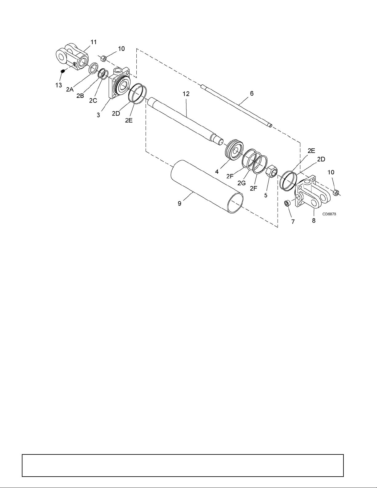
HYDRAULIC CYLINDERS
Note: The center deck uses a 3 x 8 cylinder.
Wing decks use a 3 x 10 cylinder. Verify cylinder size before ordering replacement parts.
3 x 8 3 x 10
REF PART PART QTY DESCRIPTION
1 5WP29474 5WP1031166 Complete cylinder
2 5WP19810 5WP19810 1 Seal repair kit (includes items 2A - 2G
2A † † 1 Wiper seal
2B † † 1 Rod seal
2C † † 1 Rod O-ring
2D † † 2 Cap seal
2E † † 2 Cap O-ring
2F † † 2 Piston seal
2G † † 1 Piston O-ring
3 N/S N/S 1 Cylinder housing - rod end
4N/S N/S1Piston
5N/S N/S1Jam nut
6 N/S N/S 4 Cylinder tie rod
7 * * 3 1/2 Pipe plug
8 N/S N/S 1 Cylinder housing - butt end
9 N/S N/S 2 Cylinder barrel
10 N/S N/S 8 Tie rod nut
11 N/S N/S 1 Cylinder clevis
12 N/S N/S 1 Cylinder rod
13 * * 1 Set screw 3/8 x 3/4 dog point
Included in seal kit
Standard hardware, obtain locally
Not serviced
58 Parts
(Rev. 10/30/2012)
5WPMAN0862 (11/22/2010)
Page 59

LIGHT KIT (OPTIONAL)
REF PART QTY DESCRIPTION
5WD1031385 TBW Light kit
1 5WP90401149 1 Light, 4 pin right
2 5WP90401150 1 Light, 4 pin left
3 5WP1031386 2 Light bracket
4 5WP1031388 2 Blank .16 x 4.00 x 4.00
5 5WP1004479 1 Wire harness
6 * 3/8 NC x 3-1/2 HHCS GR5
7 * 3/8 NC Flange lock nut
8 * 1/4 NC x 1 Hex head cap screw GR5
9 * 1/4 NC Lock nut
10 * #10 x 1/2 Tapping screw
1 1 * 34 Cable tie
HHCS
Hex head cap screw
* Standard hardware, obtain locally
(Rev. 10/18/2012)
5WPMAN0862 (11/22/2010)
Parts 59
Page 60

HYDRAULIC LATCH RELEASE KIT (OPTIONAL)
REF PART QTY DESCRIPTION
5WD1032454 TBW Hydraulic Latch Release Kit
1 5WP1032479 1 Release Base
2 5WP1032489 1 Slide Channel
3 5WP29547 1 3 x 8 Hydraulic Cylinder
4 5WP11893 2 Busing, Pipe Reducing 1/2 x 1/74
5 5WP10290 2 Elbow, 90° 3/32 RSTR 1/4 x 1/4
6 5WP17628 2 Hose, HP 1/4 NPT x 108
7 5WP8345 2 Pin, 1 x 4.08 Headless
8 * Cotter Pin, 1/4 x 1-1/2
9 * 1" Standard Flat Washer
10 * 3/8 NC x 1 HHCS GR5
11 * 3/8 NC Flange Lock Nut
HHCS
Hex Head Cap Screw
* Standard hardware, obtain locally
INSTALLATION INSTRUCTION
1. Remove four 1/3 NC x 2 hex head cap screws and
1/2” flat washers from top of shield on trailer.
2. Attach item 1 on top of shield using hardware
previously removed.
3. Attach i tem 2 to wing release lever using items 10
and 11.
4. Attach ba se end of cylinder (3) to item 1 us ing ite ms
7, 8, and 9. Cylinder ports should be pointing upward
.
5. Attach rod end of cylinder (3) to item 2 using items 7,
8, and 9.
6. Install reducers (4), elbows (5), and hoses to base of
cylinder.
60 Parts
(Rev. 10/18/2012)
5WPMAN0862 (11/22/2010)
Page 61

BOLT TORQUE CHART
A
SAE SERIES
TORQUE
CHART
SAE Bolt Head
Identification
SAE Grade 2
(No Dashes)
SAE Grade 5
(3 Radial Dashes)
SAE Grade 8
(6 Radial Dashes)
METRIC SERIES
TORQUE
CHART
Metric Bolt Head
Identification
8.8
Metric
Grade 10.9
10.9
Metric
Grade 8.8
A
A
Typical Washer
Installations
Lock W ash er
Flat Washer
8/9/00
Bolt
Always tighten hardware to these values unless a different torque value or tightening procedure is listed for a specific
application.
Fasteners must always be replaced with the same grade as specified in the manual parts list.
Always use the proper tool for tightening hardware: SAE for SAE hardware and Metric for metric hardware.
Make sure fastener threads are clean and you start thread engagement properly .
All torque values are given to specifications used on hardware defined by SAE J1701 MAR 99 & J1701M JUL 96.
A
Diameter
(Inches)
1/4" 7/16" 6 8 10 13 14 18
5/16"1/2"121719262737
3/8"9/16"233135474967
7/16"5/8"3648557578106
1/2" 3/4" 55 75 85 115 120 163
9/16" 13/16" 78 106 121 164 171 232
5/8" 15/16" 110 149 170 230 240 325
3/4" 1-1/8" 192 261 297 403 420 569
7/8" 1-5/16" 306 416 474 642 669 907
1" 1-1/2" 467 634 722 979 1020 1383
A
Diameter &
Thread Pitch
(Millimeters)
6 x 1.0 10 mm 8 6 11 8 8 6 11 8 6 x 1.0
8 x 1.25 13 mm 20 15 27 20 21 16 29 22 8 x 1.0
10 x 1.5 16 mm 39 29 54 40 41 30 57 42 10 x 1.25
12 x 1.75 18 mm 68 50 94 70 75 55 103 76 12 x 1.25
14 x 2.0 21 mm 109 80 151 111 118 87 163 120 14 x 1.5
16 x 2.0 24 mm 169 125 234 173 181 133 250 184 16 x 1.5
18 x 2.5 27 mm 234 172 323 239 263 194 363 268 18 x 1.5
20 x 2.5 30 mm 330 244 457 337 367 270 507 374 20 x 1.5
22 x 2.5 34 mm 451 332 623 460 495 365 684 505 22 x 1.5
24 x 3.0 36 mm 571 421 790 583 623 459 861 635 24 x 2.0
30 x 3.0 46 mm 1175 867 1626 1199 1258 928 1740 1283 30 x 2.0
Wrench
Size
Wrench
Size
MARKING ON HEAD MARKING ON HEAD
Metric 8.8 Metric 10.9 Metric 8.8 Metric 10.9
N-m lbs-ft N-m lbs-ft N-m lbs-ft N-m lbs-ft
SAE 2 SAE 5 SAE 8
lbs-ft N-m lbs-ft N-m lbs-ft N-m
COARSE THREAD FINE THREAD
MARKING ON HEAD
Diameter &
Thread Pitch
(Millimeters)
Bolt Torque & Size Charts (Rev. 3/28/2007)
Appendix 61
Page 62
BOLT SIZE CHART
NOTE: Chart shows bolt thread sizes and corresponding head (wrench) sizes for standard SAE and metric bolts.
SAE Bolt Thread Sizes
5/16 3/8 1/2 5/8 3/4 7/8
IN 1 7
2
34 5 6
MM 25 50 75 100 125 150 175
Metric Bolt Thread Sizes
8MM 18MM14MM12MM10MM 16MM
ABBREVIATIONS
AG.............................................................. Agriculture
ASABE ....................American Society of Agricultural &
Biological Engineers (formerly ASAE)
ASAE ... . ... American Society of Agric ultural Engineers
ATF................................Automatic Transmission Fluid
BSPP.............................British Standard Pipe Parallel
BSPTM................British Standard Pip e Tapered Male
CV ....................................................Constant Velocity
CCW.............................................. Counter-Clockwise
CW ..............................................................Clockwise
F.......................................................................Female
FT........................................................... ...Full Thread
GA.....................................................................Gauge
GR (5, etc.)........................................... Grade (5, etc.)
HHCS........................................Hex Head Cap Screw
HT ...........................................................Heat-Treated
JIC.................Joint Industry Council 37° Degree Flare
LH.................................................................Left Hand
LT ...........................................................................Left
m ........................................................................ Meter
mm ............................................................... Millimeter
M ..........................................................................Male
MPa ........................................................ Mega Pascal
N......................................................................Newton
NC......................................................National Coarse
NF...........................................................National Fine
NPSM .................... National Pipe Straight Mechanical
NPT...........................................National Pipe Tapered
NPT SWF......... National Pipe Tapered Swivel Female
ORBM...........................................O-Ring Boss - Male
P ..........................................................................Pitch
PBY.......................................................Power-Beyond
psi......................................... Pounds per Square Inch
PTO............. ................................. ........Power T ak e Off
QD ...................................................Quick Disconnect
RH..............................................................Right Hand
ROPS........................... Roll-Over Protective Structure
RPM........................................Revolutions Per Minute
RT........................................................................Right
SAE..........................Society of Automotive Engineers
UNC..................................................... Unified Coarse
UNF ..........................................................Unified Fine
UNS.....................................................Unified Special
62 Appendix
Bolt Torque & Size Charts (Rev. 3/28/2007)
Page 63

INDEX
Adjustments
Cutting Height
Leveling Mower 14
Dealer Check List
Delivery Check (Dealer’s Responsibility)
Pre-Delivery Check List (Dealer’s Responsibility)
15
39
39
Dealer Service
Blade Spindle
Assembly
Disassembly 28
Installation 29
Removal 27
Repair 27
Service 27
Drive Sheave Installation 32
Gearbox
Disassembly
Horizontal Leak Repair 31
Installation 32
Reassembly 31
Removal from Mower 29
Repair 29
Seal Installation 30
Seal Replacement 29
Service 29
Vertical Shaft Repair 30
Universal Joint
Assembly
Disassembly 32
Repair 32
General
Abbreviations
Bolt Size Chart 62
Bolt Torque Chart 61
General information 4
Introduction 2
Specifications 3
Table of Contents 3
Operation
Attaching Mower to Tractor
Attaching Hydraulic Hoses 14
Check List
Pre-Operation (Owners Responsibility)
Cutting Height Adjustment 15
CV Driveline Turning Limits 14
Leveling Mower 14
Operating 16
On Uneven Terrain 17
Technique 17
Tips 17
Removing Mower from Tractor 17
Starting and Stopping Mower 16
Transport 16
28
31
33
62
13
18
Owner Service
Belt
Installation
FM1012 Rear Deck
FM1012 Wing Deck 22
FM1015 & FM1017 All Decks 22
Replacement 22
Routing 22
Blade
Installation
Servicing 23
Blocking Method 19
Clean Cutter
After Each Use
Periodically or Before Extended Storage 24
Lubrication
Information
Parts
Parts Index
Safety
Blocking Method
Check List
Delivery Check List (Dealer’s Responsibility)
41
39
Pre-Delivery Check List (Dealer’s Responsibili-
39
ty)
Check Lists
Pre-Operation (Owner’s Responsibility)
Safety Decals 9
Safety Rules 5
Trouble Shooting
Belt Conditions
Mowing Conditions 25
22
23
24
20, 21
19
18
26
MAN0826 (8/31/2010)
Index 63
Page 64

PART NUMBER
5WPMAN0862
©2002 Woods Equipment Company. All rights reserved. WOODS and the Woods logo are trademarks of Woods Equipment Company. Frontier
Equipment and the Frontier logo are trademarks of Deere & Company. All other trademarks, trade names, or service marks that appear in this manual are the property of their respective companies or mark holders. Specifications subject to change without notice.
 Loading...