

Page 1
OPERATOR’S MANUAL
OMM144042
Issue D0
Lawn and Garden Tractors
425 and 445
Serial No. (070001 -)
Page 2

Introduction........................................................................................................................... 6
Thank You for Purchasing a John Deere Product............................................................. 6
Using Your Operator's Manual......................................................................................... 6
CALIFORNIA Proposition 65 Warning...........................................................................7
Product Identification............................................................................................................ 8
Record Identification Numbers......................................................................................... 8
Safety .................................................................................................................................... 9
Safety-Alert Symbol ......................................................................................................... 9
WARNING: AVOID SERIOUS INJURY OR DEATH .................................................. 9
DANGER: ROTATING BLADES CUT OFF ARMS AND LEGS .............................. 10
DANGER: EXPLOSIVE GASES .................................................................................. 10
HOT SURFACE ............................................................................................................. 11
CAUTION: PRESSURIZED LINE................................................................................ 11
Emission Control System Certification Label ................................................................ 11
Emission Compliance Period.......................................................................................... 12
Certification .................................................................................................................... 12
Operate Safely................................................................................................................. 12
Park Safely...................................................................................................................... 13
Rotating Blades are Dangerous - Protect Children and Prevent Accidents.................... 13
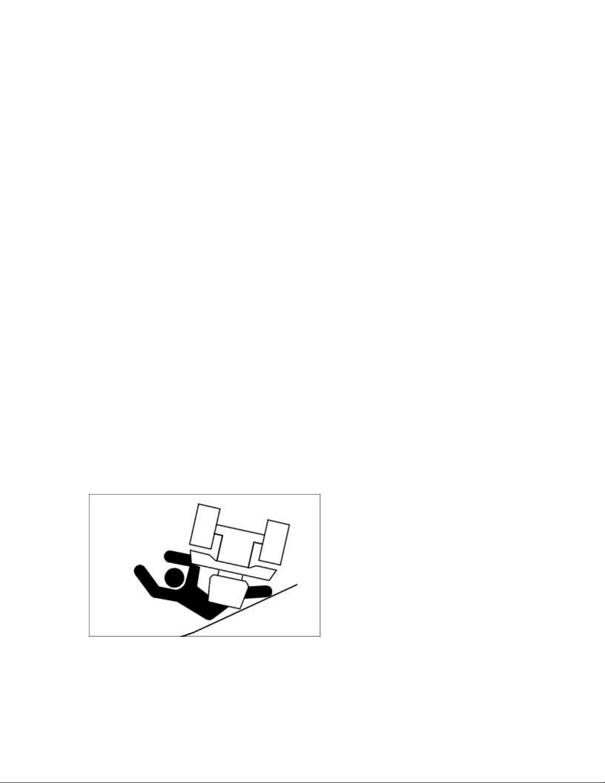
Avoid Tipping................................................................................................................. 14
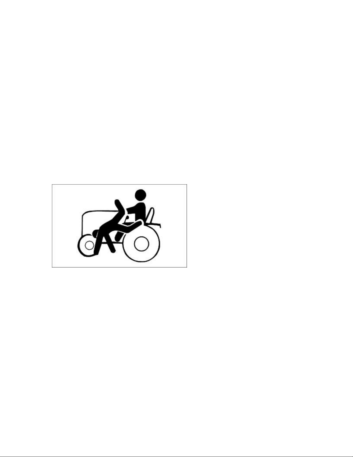
Keep Riders Off.............................................................................................................. 15
Wear Appropriate Clothing............................................................................................. 15
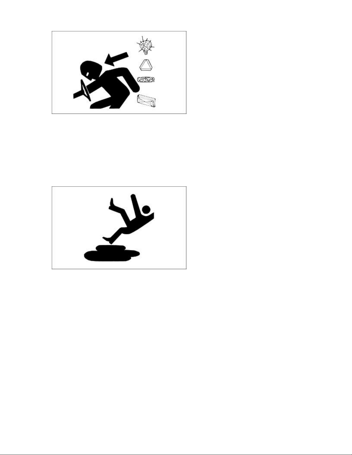
Stay Clear of Rotating Drivelines................................................................................... 16
Check Wheel Bolts ......................................................................................................... 16
Transport Safely.............................................................................................................. 16
Practice Safe Maintenance.............................................................................................. 17
Wear Appropriate Clothing............................................................................................. 18
Stay Clear of Rotating Drivelines................................................................................... 18
Handling Waste Product and Chemicals......................................................................... 18
Avoid High Pressure Fluids............................................................................................ 19
Operating............................................................................................................................. 21
Daily Operating Checklist............................................................................................... 21
Dash Controls.................................................................................................................. 21
Foot/Platform Controls ................................................................................................... 22
Miscellaneous Controls................................................................................................... 23
Adjusting Steering Wheel............................................................................................... 24
Adjusting Seat (425)....................................................................................................... 24
Adjusting Seat (445)....................................................................................................... 25
Rear Wheel Spacing (Two Wheel Steer Models With 23 x 10.50-12 Tires) ................. 26
Testing Safety Systems................................................................................................... 27
Test 1............................................................................................................................... 27
Test 2............................................................................................................................... 28
Test 3............................................................................................................................... 28
Test 4............................................................................................................................... 29
Test 5............................................................................................................................... 29
Test 6............................................................................................................................... 30
Using the Park Brake...................................................................................................... 31
Indicator Lights and Gauges........................................................................................... 31
2
Page 3

Starting the Engine.......................................................................................................... 33
Stopping the Engine........................................................................................................ 35
Using Travel Controls..................................................................................................... 36
Using Cruise Control ...................................................................................................... 37
Using The Reverse Implement Option ........................................................................... 38
Using Differential Lock.................................................................................................. 39
Using Hydraulic Control Levers..................................................................................... 40
Using PTO (Power Take-Off)......................................................................................... 41
Using Mower Height Control ......................................................................................... 42
Mower Lift Arms............................................................................................................ 43
Using Free-Wheeling Lever............................................................................................ 43
Using Engine Air Restriction Indicator (Optional Equipment)...................................... 44
Using Weights And Tire Chains..................................................................................... 45
Rear Weights................................................................................................................... 45
Installing Rear Wheel Weights (Two-Wheel Steer Tractors)......................................... 45
Installing Rear Wheel Weights (All-Wheel Steer Tractors)........................................... 49
Using Tire Chains........................................................................................................... 50
Installing the Chains ....................................................................................................... 50
Transporting Tractor....................................................................................................... 52
Mowing Tips................................................................................................................... 53
Trimming Tips................................................................................................................ 54
To Avoid Scalping.......................................................................................................... 54
After Mowing.................................................................................................................. 54
Bagging Tips................................................................................................................... 55
Bagging and Composting................................................................................................ 55
Mulching Tips................................................................................................................. 56
Replacement Parts............................................................................................................... 57
Service Literature............................................................................................................ 57
Parts................................................................................................................................. 57
Part Numbers .................................................................................................................. 57
Service Interval Chart......................................................................................................... 59
After First 5 Hours.......................................................................................................... 59
Break In (After First 50 Hours of Operation)................................................................. 59
50 Hours.......................................................................................................................... 59
100 Hours or Annually (whichever comes first)............................................................. 59
200 Hours........................................................................................................................ 59
200 Hours or Annually (whichever comes first)............................................................. 59
250 Hours or Annually (whichever comes first)............................................................. 60
500 Hours........................................................................................................................ 60
500 Hours or Every Two Years (whichever comes first)............................................... 60
Service Lubrication............................................................................................................. 61
Grease ............................................................................................................................. 61
Lubricating Rear Steering Pivot (All Wheel Steer)........................................................ 61
Lubricating Steering Cylinder Ball Joints (All Tractors) ............................................... 62
Lubricating Front Axle ................................................................................................... 63
Service Engine.................................................................................................................... 65
Engine Warranty Maintenance Statement ...................................................................... 65
Adjusting Carburetor ...................................................................................................... 65
Avoid Fumes................................................................................................................... 65
Engine Oil....................................................................................................................... 65
3
Page 4

Changing Engine Oil and Filter...................................................................................... 68
Cleaning Air Intake Screens ........................................................................................... 70
Checking Air Restriction Indicator (Optional Equipment)............................................. 71
Cleaning Radiator Screen and Fins................................................................................. 71
Servicing Air Cleaner Elements...................................................................................... 72
Recommended Engine Coolant....................................................................................... 75
Engine Coolant Drain Interval........................................................................................ 75
Engine Coolant Drain Interval........................................................................................ 76
Checking Coolant Level ................................................................................................. 76
Servicing Cooling System............................................................................................... 77
Replacing Fuel Filter (425)............................................................................................. 82
Relieving Fuel System Pressure (445)............................................................................ 82
Replacing Fuel Filter (445)............................................................................................. 83
Servicing Fan Belt........................................................................................................... 84
Service Transmission.......................................................................................................... 87
Anti-Chatter Transmission Oil........................................................................................ 87
Checking Transaxle Oil Level........................................................................................ 87
Changing Transaxle Oil and Filter.................................................................................. 88
Service Electrical................................................................................................................ 91
Cleaning or Replacing Battery........................................................................................ 91
Checking Battery Electrolyte Level................................................................................ 93
Charging the Battery....................................................................................................... 94
Using Booster Battery..................................................................................................... 96
Cleaning and Gapping Spark Plugs ................................................................................ 97
Replacing Fuses.............................................................................................................. 99
Replacing Headlight Bulb............................................................................................. 100
Replacing Taillight Bulb............................................................................................... 100
Replacing Indicator Light Bulb .................................................................................... 101
Service Miscellaneous ...................................................................................................... 104
Checking Tire Pressure................................................................................................. 104
Checking Tightness of Wheel Bolts ............................................................................. 105
Raising Hood ................................................................................................................ 105
Removing Grille............................................................................................................ 106
Removing and Cleaning Side Panels............................................................................ 106
Refueling Machine........................................................................................................ 108
Filling Fuel Tank........................................................................................................... 109
Cleaning and Repairing Plastic Surfaces...................................................................... 110
Cleaning and Repairing Metal Surfaces ....................................................................... 110
Troubleshooting................................................................................................................ 112
Using Troubleshooting Chart........................................................................................ 112
Engine........................................................................................................................... 112
Tractor........................................................................................................................... 113
Steering......................................................................................................................... 114
Mower........................................................................................................................... 114
Electrical....................................................................................................................... 114
Storing Machine................................................................................................................ 116
Storage Safety............................................................................................................... 116
Preparing Engine for Storage........................................................................................ 116
Storing the Tractor........................................................................................................ 116
Removing the Vehicle From Storage............................................................................ 117
4
Page 5

Assembly........................................................................................................................... 119
Remove Bracing............................................................................................................ 119
Fill Fuel Tank Safely .................................................................................................... 119
Fill Fuel Tank................................................................................................................ 119
Activate Battery (Early Model Dry Batteries).............................................................. 120
Check Battery Voltage (Late Model "Moist" Batteries)............................................... 122
Install Battery................................................................................................................ 123
Install the Steering Wheel............................................................................................. 124
Install Seat (425)........................................................................................................... 124
Install Seat (445)........................................................................................................... 125
Checking Tire Pressure................................................................................................. 126
Specifications.................................................................................................................... 128
Engine........................................................................................................................... 128
Engine........................................................................................................................... 128
Fuel System................................................................................................................... 129
Electrical System .......................................................................................................... 129
Capacities...................................................................................................................... 129
Drive Train.................................................................................................................... 130
Travel Speeds................................................................................................................ 130
Steering and Brakes ...................................................................................................... 130
Dimensions - 425.......................................................................................................... 130
Dimensions - 445.......................................................................................................... 131
Tires - 425..................................................................................................................... 132
Tires - 445..................................................................................................................... 132
Recommended Lubricants ............................................................................................ 132
Warranty ........................................................................................................................... 133
Product Warranty.......................................................................................................... 133
Tire Warranty................................................................................................................ 133
John Deere, Federal and California Emission Control System Warranty (Small Off-
Road Gas Engines)........................................................................................................ 133
Limited Battery Warranty............................................................................................. 137
John Deere Quality Statement .......................................................................................... 139
John Deere Quality ....................................................................................................... 139
Service Record.................................................................................................................. 141
Record Service Dates.................................................................................................... 141
5
Page 6

Introduction
Thank You for Purchasing a John Deere Product
We appreciate your business and wish you many years of safe and satisfied use of your machine.
Using Your Operator's Manual
This manual is an important part of your machine and should remain with the machine when you sell
it.
Reading your operator's manual will help you and others avoid personal injury or damage to the
machine. Information given in this manual will provide the operator with the safest and m ost effective
use of the machine. Knowing how to operate this machine safely and correctly will allow you to train
others who may operate this machine.
Section in your operator's manual are placed in a specific order to help you understand all the safety
messages and learn the controls so you can operate this machine safely. YOu can also use this manual
to answer any specific operating or servicing questions. A convenient index located at the end of this
book will help you to find needed information quickly.
The machine shown in this manual may differ slightly from your machine, but will be similar enough
to help you understand our instructions.
RIGHT-HAND and LEFT-HAND sides are determined by facing in the direction the machine will
travel when going forward. When you see a broken line arrow (------>), the item referred to is hidden
from view.
Special Messages
Your manual contains special messages to bring attention to potential safety concerns, m achine
damage as well as helpful operating and servicing information. Please read all the highlighted
information carefully to avoid injury and machine damage.
6
Page 7
c CAUTION: Avoid injury!
This symbol and text highlight potential hazards or death to the operator or bystanders may occur if
the hazards or procedures are ignored.
IMPORTANT: Avoid damage!
This text is used to tell the operator of actions or conditions that might result in damage to the
machine.
NOTE: General information is given throughout the manual that may help the operator in the
operation of the machine.
CALIFORNIA Proposition 65 Warning
WARNING: The Engine Exhaust from this product contains chemicals known to the State
of California to cause cancer, birth defects or other reproductive harm.
California Proposition 65 Warning
7
Page 8
Product Identification
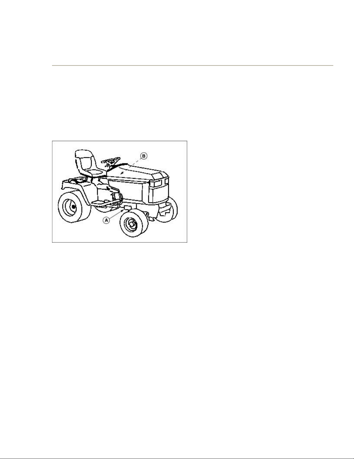
Record Identification Numbers
If you need to contact an Authorized Service Center for information on servicing, always provide the
product model and serial number.
You will need to locate the model and serial number for the machine and for the engine of your
machine and record the information in the spaces provided below.
M71459A
DATE OF PURCHASE:
_________________________________________
DEALER NAME:
_________________________________________
DEALER PHONE:
_________________________________________
PRODUCT IDENTIFICATION NUMBER (A):
__ __ __ __ __ __ __ __ __ __ __ __ __ __ __ __ __
ENGINE SERIAL NUMBER (B):
__ __ __ __ __ __ __ __ __ __ __ __ __ __ __ __ __
8
Page 9
Safety
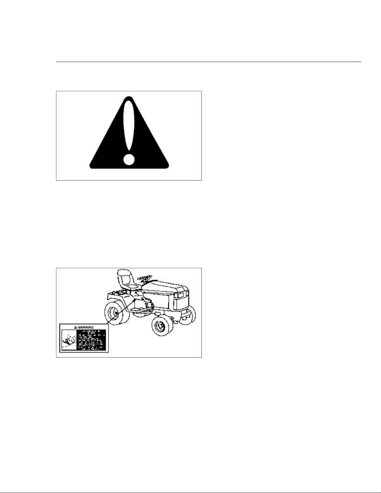
Safety-Alert Symbol
Read and recognize safety information. Be alert to the potential for personal injury when you see this
safety-alert symbol.
On your machine safety labels, the words DANGER, WARNING, and CAUTION are used with this
safety-alert symbol. DANGER identifies the most serious hazards. In this manual, the word
CAUTION and this symbol call attention to safety messages.
WARNING: AVOID SERIOUS INJURY OR DEATH
m40180A
· Drive up and down slopes, not across.
· Avoid sudden turns.
· If machine stops going uphill, stop blade and back down slowly.
· Keep safety devices (guards, shields, and switches) in place and working.
9
Page 10
· Read Operator's Manual.
· When leaving machine: Stop engine, Set park brake, Remove key.
DANGER: ROTATING BLADES CUT OFF ARMS AND LEGS
M140180B
· Do not mow when children or others are around.
· Do not mow in reverse.
· Look down and behind before and while backing.
· Never carry children even with the blades off.
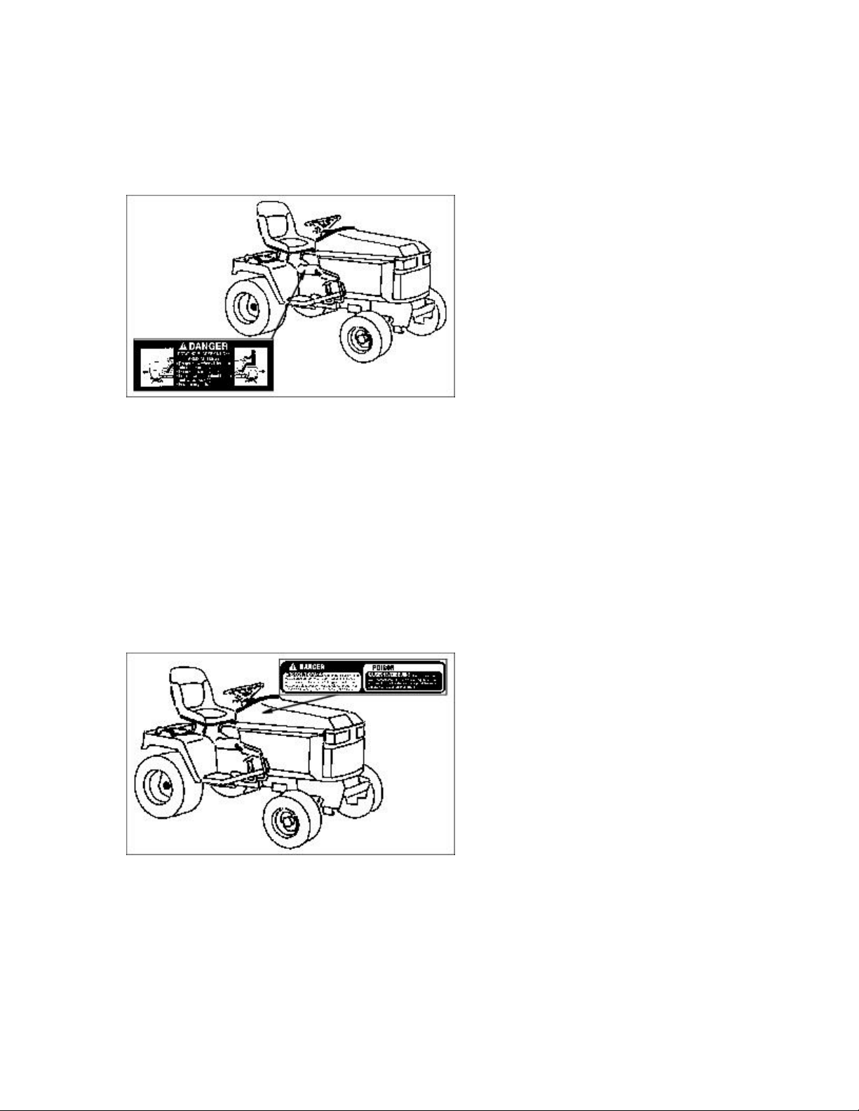
DANGER: EXPLOSIVE GASES
M74408
Cigarettes, flames or sparks could cause battery to explode. Always shield eyes and face from battery.
Don not charge or use booster cables or adjust post connections without proper instruction and
training. Keep vent caps tight and level.
POISON: CAUSES SEVERE BURNS
10
Page 11
Contains sulfuric acid. Avoid contact with skin, eyes or clothing. In event of accident, flush with
water and call a physician immediately. Keep out of reach of children.
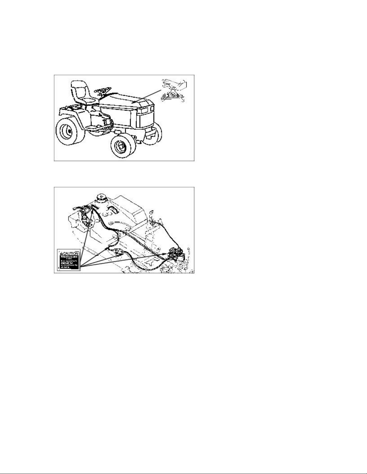
HOT SURFACE
CAUTION: PRESSURIZED LINE
M71542 M71535
See operator's manual for instructions to remove.
Emission Control System Certification Label
NOTE: Tampering with emission controls and components by unauthorized personnel may result in
severe fines or penalties. Emission controls and components can only be adjusted by EPA and/or
CARB authorized service centers. Contact your John Deere Commercial and Consumer Equipment
Retailer concerning emission controls and component questions.
The presence of an emissions label signifies that the engine has been certified with the United States
Environmental Protection Agency (EPA) and/or California Air Resources Board (CARB).
The emissions warranty applies only to those engines marketed by John Deere that have been
certified by the EPA and/or CARB; and used in the United States and Canada in off-road mobile
equipment.
11
Page 12
Emission Compliance Period
If your engine has the emission compliance category listed on the emission control system
certification or air index label, this indicates the number of operating hours for which the engine has
been certified to meet EPA and/or CARB emission requirements. The following table provides the
engine compliance period in hours associated with the category found on the certification label.
Agency Category Hours
EPA C 250
EPA B 500
EPA A 1000
CARB Moderate 125
CARB Intermediate 250
CARB Extended 500
Certification
Your mower has been certified by an independent laboratory for compliance with American National
Standard B-71.1, "Safety Specifications" for Power Lawn Mowers, Lawn and Garden Tractors, and
Lawn Tractors.
Operate Safely
· Check brake action before you operate. Adjust or service brakes as necessary.
· Inspect machine before you operate. Be sure hardware is tight. Repair or replace damaged, badly
worn, or missing parts. Be sure guards and shields are in good condition and fastened in place. Make
any necessary adjustments before you operate.
· Clear work area of objects that might be thrown. Keep people and pets out of the work area. Stop
12
Page 13
machine if anyone enters the area.
· If you hit an object, stop the machine and inspect it. Make repairs before you operate. Keep machine
and attachments properly maintained and in good working order.
· DO NOT leave machine unattended when it is running.
· Only operate during daylight or with good artificial light.
· Be careful of traffic when operating near or crossing roadways.
· Do not wear radio or music headphones while operating the machine. Safe operation requires your
full attention.
· Older adults are involved in a large percentage of riding mower accidents involving injury. These
operators should evaluate their ability to operate a mower safely enough to protect the operator and
others from serious injury.
Park Safely
· Stop machine on a level surface, not on a slope.
· Disengage PTO.
· Lower attachments to the ground.
· Engage park brake.
· STOP engine.
· Remove key.
· Before you leave the operator's seat, wait for engine and all moving parts to STOP.
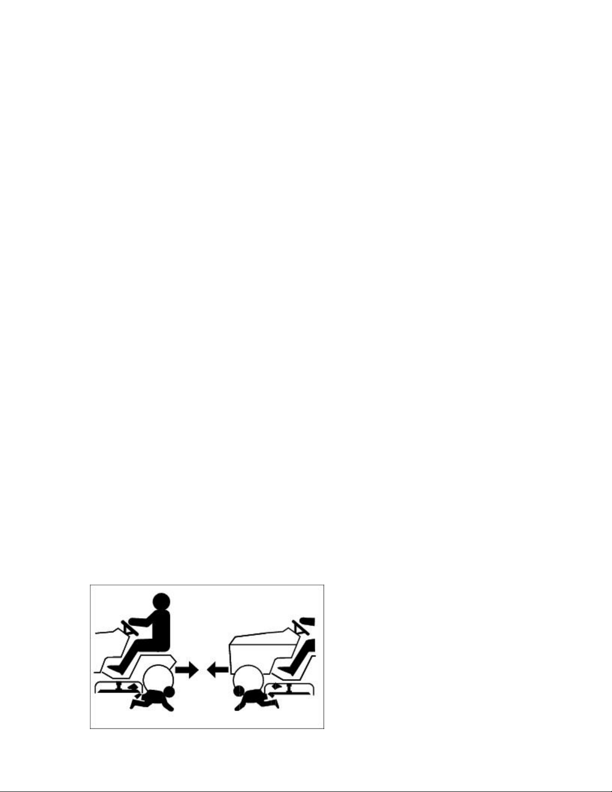
Rotating Blades are Dangerous - Protect Children and Prevent Accidents
Protect Children
13
Page 14
· Never assume that children will remain where you last saw them. Children are attracted to mowing
activity, stay alert to the presence of children.
· Keep children in the house when you are operating the machine.
· Turn machine off if a child enters the mowing area.
· Use extra care when you come to blind corners, shrubs, trees, or other objects that may block your
vision.
· DO NOT let children or an untrained person operate the machine.
· DO NOT carry or let children ride on machine or any attachment even with blades off. DO NOT tow
children in a cart or trailer.
Help Prevent Serious Or Fatal Accidents:
· Be alert at all times, drive forward carefully. People ESPECIALLY CHILDREN can move quickly
into the mowing area before you know it.
· Back carefully. Shut off PTO and look behind the machine carefully, ESPECIALLY FOR
CHILDREN, before you back up.
· DO NOT mow in reverse unless it is absolutely necessary.
· Shut off PTO when you are not mowing.
· DO NOT operate machine if you are under the influence of drugs or alcohol.
Avoid Tipping
· DO NOT drive where machine could slip or tip.
· Stay alert for holes and other hidden hazards in the terrain.
14
Page 15
· Keep away from drop-offs.
· Slow down before you make a sharp turn or operate on a slope.
· When pulling loads or using heavy equipment, use only approved hitches, limit loads to those you
can safely control, and use counterweights or wheel weights when required per this manual or your
attachment manual.
· Drive up and down a hill - not across. Be careful when you change direction on a slope.
· DO NOT stop when going up hill or down hill. If machine stops going up hill, STOP PTO and back
down slowly.
· DO NOT mow wet grass. Reduced traction could cause sliding.
· DO NOT try to stabilize the machine by putting your foot on the ground.
Keep Riders Off
· Only allow the operator on the machine. Keep riders off.
· Riders on the machine or attachment may be struck by foreign objects or thrown off the machine
causing serious injury.
· Riders obstruct the operator's view resulting in the machine being operated in an unsafe manner.
Wear Appropriate Clothing
15
Page 16
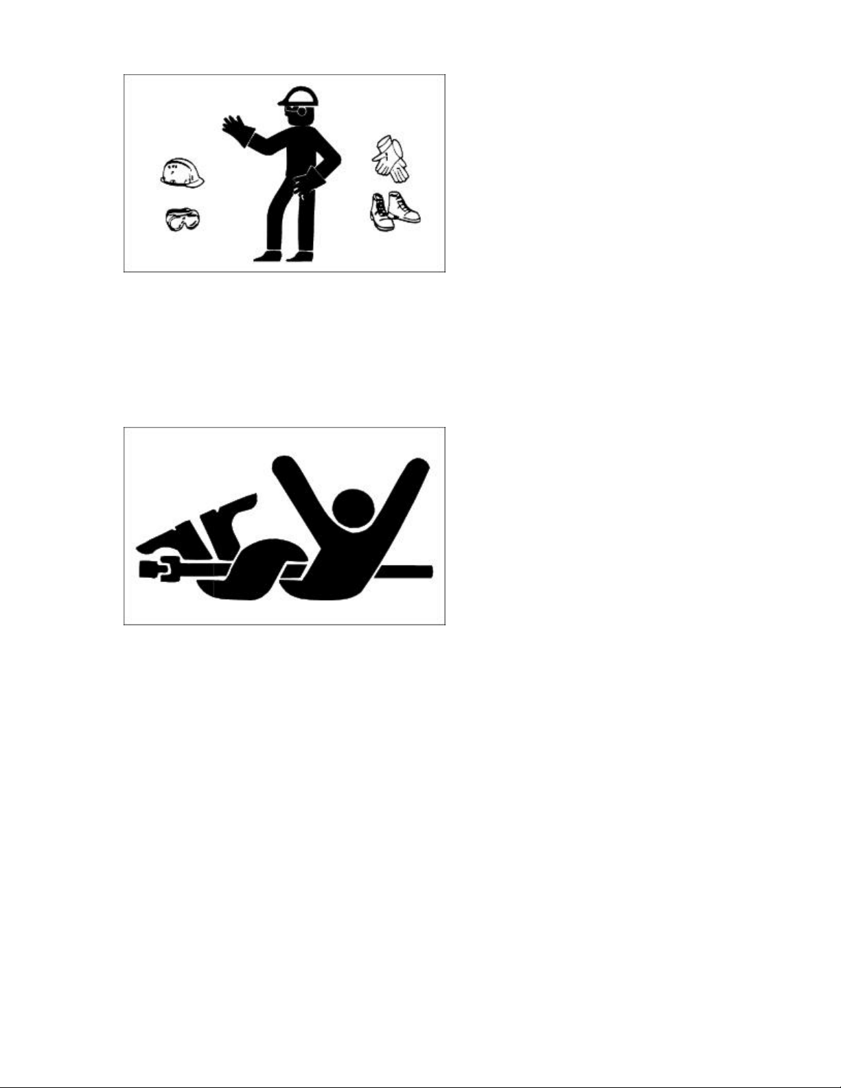
· Wear close fitting clothing and safety equipment appropriate for the job.
· Loud noise can cause impairment or loss of hearing, wear a suitable protective device such as
earplugs.
Stay Clear of Rotating Drivelines
Entanglement in rotating driveline can cause serious injury or death:
· Wear close fitting clothing.
· STOP the engine and be sure PTO driveline is stopped before getting near it.
Check Wheel Bolts
· A serious accident could occur causing serious injury if wheel bolts are not tight.
· Check wheel bolt tightness often during the first 100 hours of operation.
Transport Safely
16
Page 17
· Use safety lights and devices. Slow moving machines when driven on public roads are hard to see,
especially at night. Avoid personal injury or death resulting from a collision with a vehicle.
· Whenever driving on public roads, use flashing warning lights and turn signals according to local
regulations. Extra flashing warning lights may need to be installed.
Practice Safe Maintenance
· Understand service procedure before doing work. Keep area clean and dry.
· Never lubricate, service, or adjust machine while it is moving. Keep safety devices in place and in
working condition. Keep hardware tight.
· To prevent them from getting caught, keep hands, feet, clothing, jewelry, and long hair away from
any moving parts.
· Before servicing machine, lower attachments to the ground. Disengage all power and stop the
engine. Move hydraulic lift levers back and forth to relieve pressure. Lock park brake and remove the
key. Let tractor cool.
· Securely support any machine elements that must be raised for service work.
· Never run engine unless park brake is locked.
· Keep all parts in good condition and properly installed. Fix damage immediately. Replace worn or
17
Page 18
broken parts. Remove any buildup of grease, oil, or debris.
· Disconnect battery ground cable (-) before making adjustments on electrical systems or welding on
tractor.
· Unauthorized modifications to the tractor may impair its function and safety.
Wear Appropriate Clothing
· Wear close fitting clothing and safety equipment appropriate for the job.
· Loud noise can cause impairment or loss of hearing, wear a suitable protective device such as
earplugs.
· Do not wear radio or music headphones while servicing the machine. Safe service requires your full
attention.
Stay Clear of Rotating Drivelines
Entanglement in rotating driveline can cause serious injury or death:
· STOP the engine and be sure PTO driveline is stopped before getting near it.
Handling Waste Product and Chemicals
18
Page 19
· Waste products, such as, used oil, fuel, coolant, brake fluid, and batteries, can harm the environment
and people.
· DO NOT use beverage containers for waste fluids-someone may drink from them.
· See your local Recycling Center or John Deere dealer to learn how to recycle or get rid of waste
products.
· A Material Safety Data Sheet (MSDS) provides specific details on chemical products: physical and
health hazards, safety procedures, and emergency response techniques. See your John Deere dealer
for the MSDS on chemical products used with your machine.
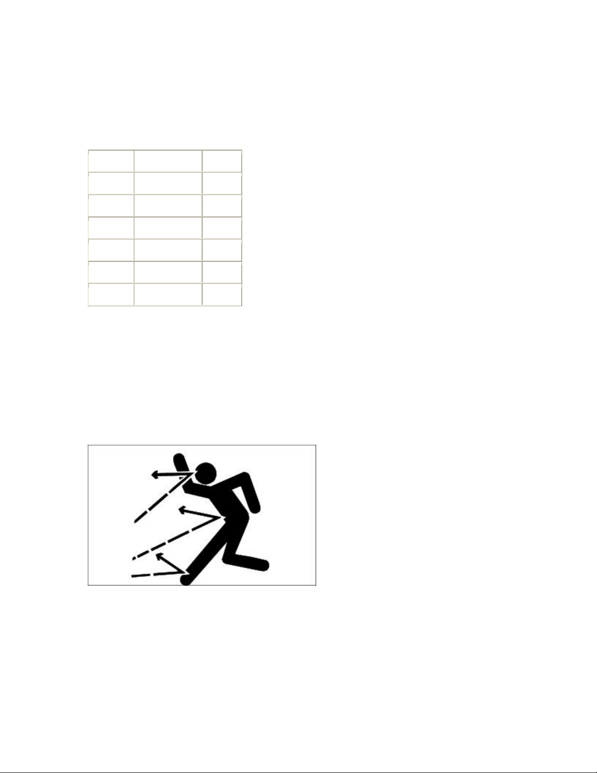
Avoid High Pressure Fluids
· Hydraulic hoses can fail due to physical damage, kinks, age, and exposure. Check hoses regularly.
Replace damaged hoses.
· Escaping fluid under pressure can penetrate the skin causing serious injury. Avoid the hazard by
relieving pressure before disconnecting hydraulic or other lines. Tighten all connections before
applying pressure.
· Search for leaks with a piece of cardboard. Protect hands and body from high pressure fluids.
· If an accident occurs, see a doctor immediately. Any fluid injected into the skin must be surgically
removed within a few hours or gangrene may result. Doctors unfamiliar with this type of injury
should reference a knowledgeable medical source. Such information is available from Deere &
19
Page 20

Company Medical Department in Moline, Illinois, U.S.A.
20
Page 21
Operating
Daily Operating Checklist
o Test safety systems.
o Check tire pressure.
o Check fuel level.
o Check engine oil level.
o Check transaxle oil level.
o Check coolanat level.
o Check Air Restriction Indicator (if so equipped).
o Clean air intake screens.
o Remove grass and debris from machine.
Dash Controls
M71462
A - Hydraulic Control Levers
B - Throttle Lever
21
Page 22
C - Indicator Lights
D - LIght Switch
E - Choke Lever (425)
F - PTO Switch
G - Key
H - Tilt Steering Wheel Button
I - Park Brake Lever
M71463
A - Cruise Control Lever
Foot/Platform Controls
M71462
22
Page 23
A - Differential Lock Pedal
B - Brake Pedal
C - Reverse Travel Pedal
D - Forward Travel Pedal
E - Mower Height Indicator
F - Mower Height Crank
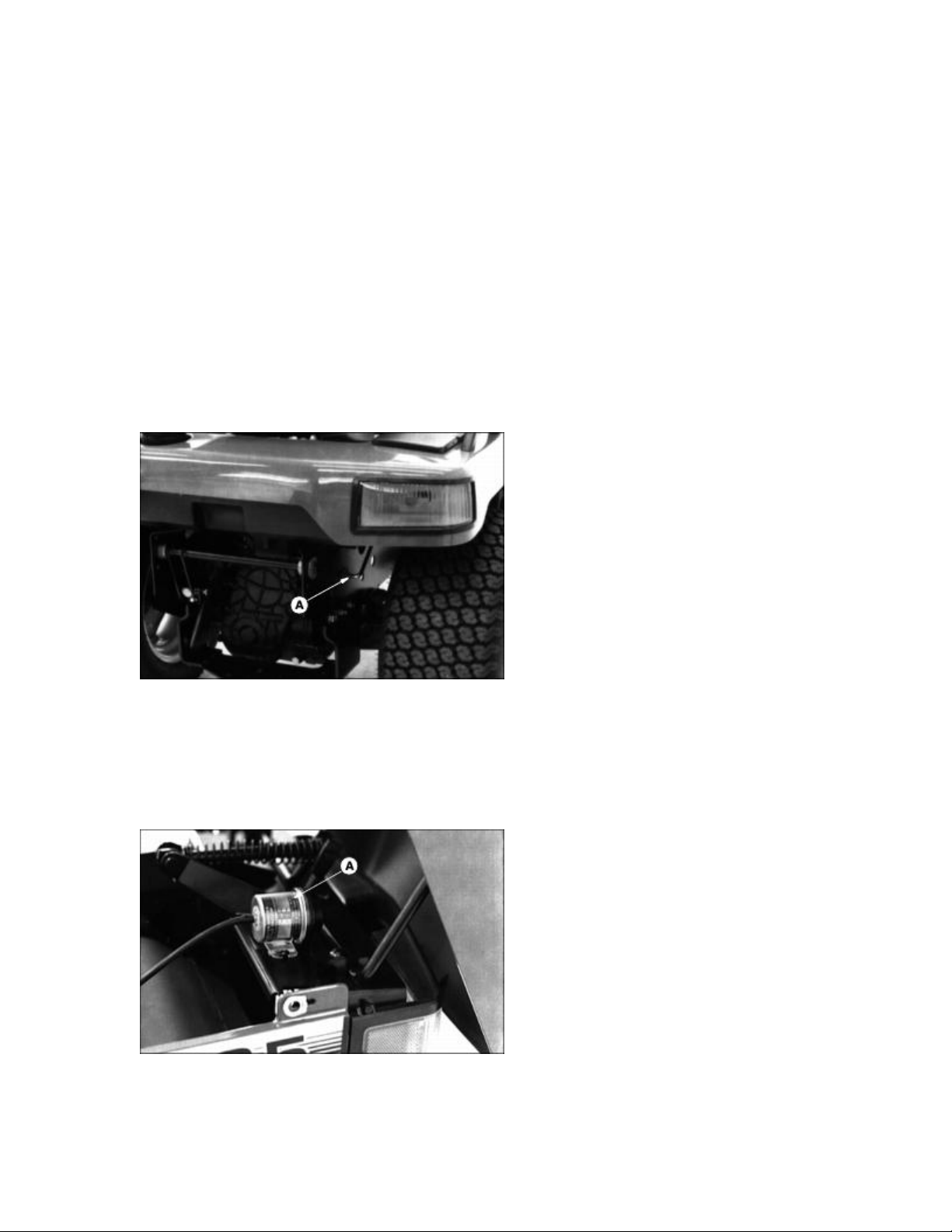
Miscellaneous Controls
Free Wheeling Lever
M71465
A - Free-Wheeling Lever
Air Restriction Indicator
M71510
A - Air Restriction Indicator (Optional)
23
Page 24
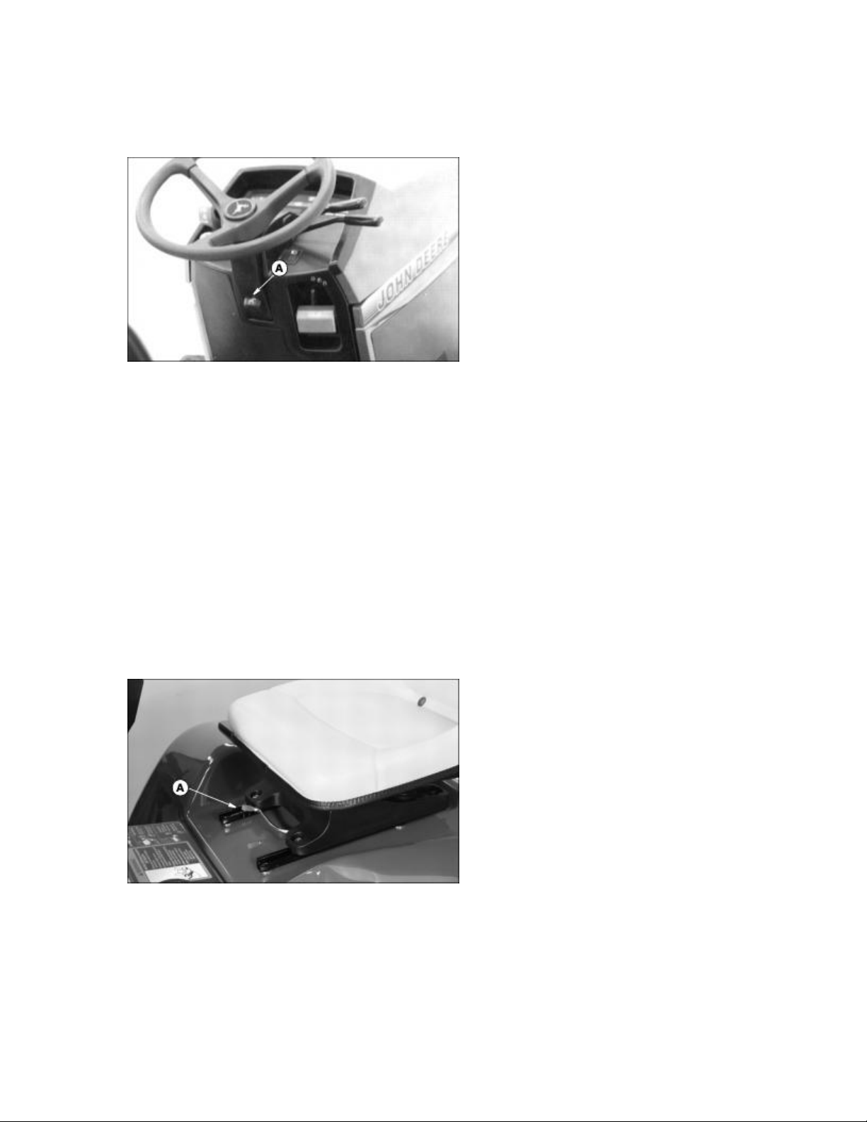
Adjusting Steering Wheel
NOTE: Steering wheel has four tilt positions.
M71475
1. Push in button (A) and push or pull wheel to a comfortable operating position.
2. Release button.
NOTE: Before operating, be sure steering wheel is locked in position.
Adjusting Seat (425)
Adjust Forward / Rearward
NOTE: This tractor is equipped with a fourteen position slide rail seat. Be sure seat is locked in
position before operating.
M96042
1. Push lever (A) to the left.
2. Slide seat forward or backward to desired position.
3. Release lever.
24
Page 25
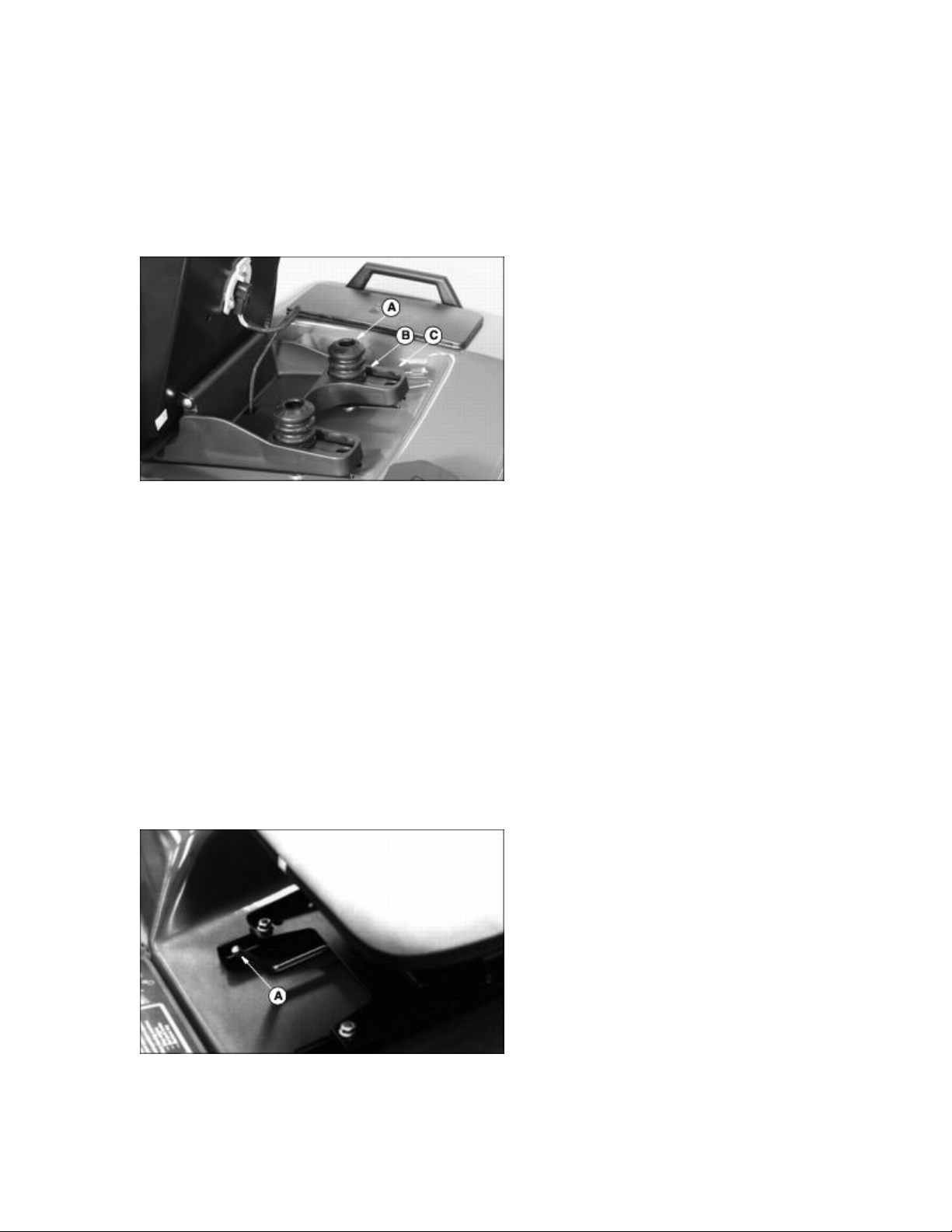
Adjust Seat Suspension
NOTE: Seat suspension can be adjusted to better match the weight of the operator.
1. Lift operators seat.
2. Suspension coils can be moved to three different settings:
M96043
· Soft Ride (A)
· Average Ride (B)
· Firm Ride (C)
3. Make sure suspension coils are in the same ride setting for each side.
Adjusting Seat (445)
NOTE: This tractor is equipped with a fourteen position slide rail seat. Be sure seat is locked in
position before operating.
M71483
1. Push lever (A) to the left.
25
Page 26
2. Slide seat forward or backward to desired position.
3. Release lever.
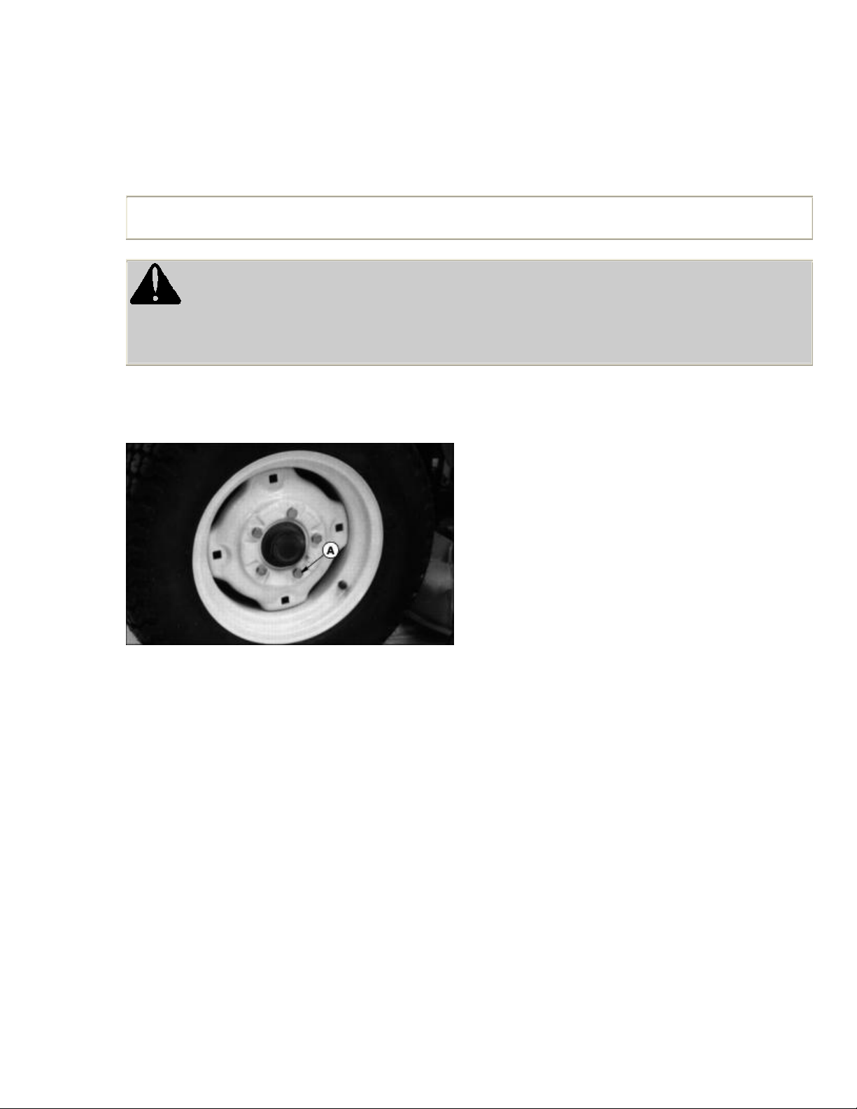
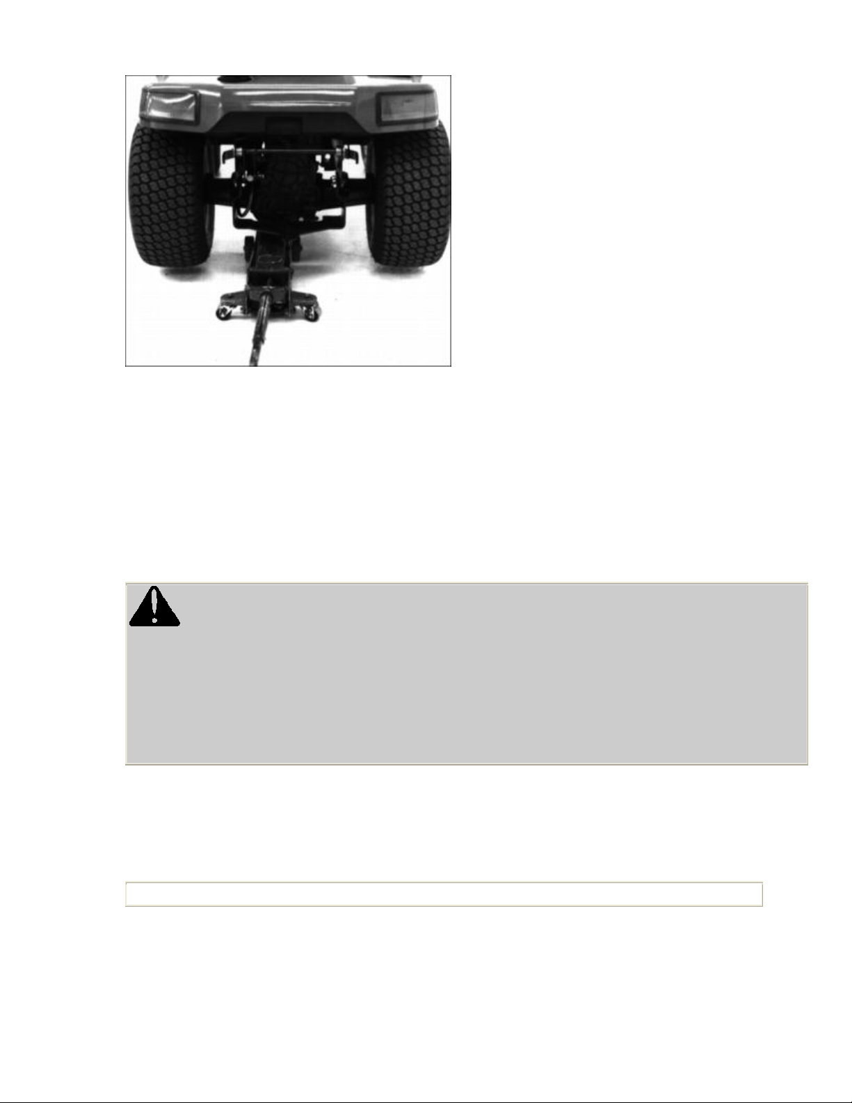
Rear Wheel Spacing (Two Wheel Steer Models With 23 x 10.50-12 Tires)
IMPORTANT: Avoid damage! On 26 x 12.00-12 tire option, wheels should always be in the wide
position.
c CAUTION: Avoid injury! Do not work under a raised tractor unless it is safely supported. A tractor
that slips and falls off a jack could cause serious injury or death.
1. Park tractor on level surface. STOP engine. LOCK park brake. Put blocks in front and back of front
wheels.
M71459
2. Loosen five rear wheel bolts (A). Lift rear wheels off the ground with floor jack or hoist.
3. Remove wheel bolts.
4. Install wheels as follows:
· Turf tires: Install wheel on same side of tractor with valve stem inside.
26
Page 27
M71484
· Bar tires: Install each wheel on opposite side of tractor. Bars on tires must point forward.
· Tighten wheel bolts to 88 N·lm (65 lb-ft).
· Lower rear wheels to the ground. Remove blocks from front wheels.
Testing Safety Systems
c CAUTION: Avoid injury! Engine exhaust fumes can cause sickness or death.
· If it is necessary to run an engine in an enclosed area, remove the exhaust fumes for the area with
an exhaust pipe extension.
· If you do not have an exhaust pipe extension, open the doors and get outside air into the area.
Use the following checkout procedure to check for normal operation of tractor.
If there is a malfunction during one of these procedures, DO NOT operate tractor. (See your John
Deere dealer for service.)
IMPORTANT: Avoid damage! Tests 1, 2 and 3 are performed WITHOUT the engine running.
Perform these tests in a clear open area. Keep bystanders away.
Test 1
27
Page 28
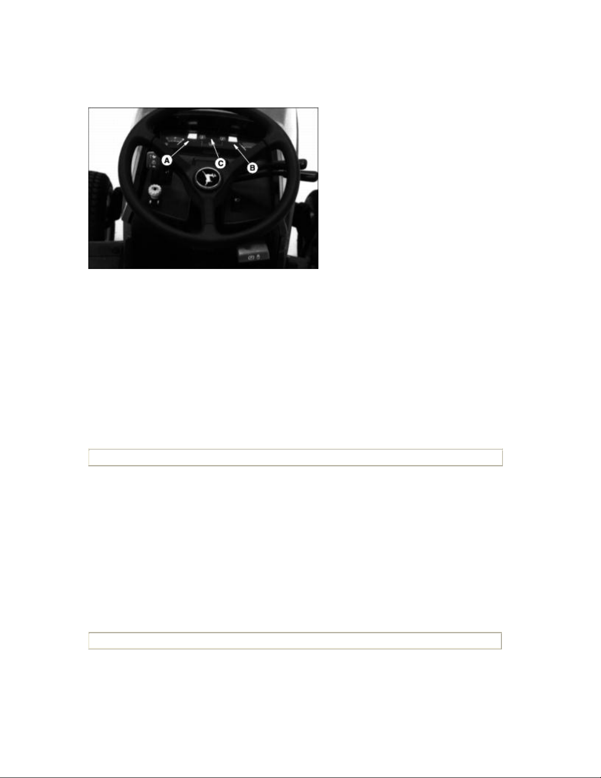
Check operation of indicator lights:
· Turn key to RUN position.
M71630
· LOOK: Indicator lights (A) and (B) must light.
· LOOK: On Model 445, indicator light (C) will come on and go out in two to three seconds.
· If one indicator does not light, see Replacing Indicator Light Bulb in Service-Electrical section.
· If new indicator bulb does not light or no indicators work, see your John Deere dealer.
Test 2
IMPORTANT: Avoid damage! If test fails, the engine may start and tractor may move.
Test brake switch:
1. Unlock park brake and release brake pedal.
2. Turn key to START position.
3. Engine must not crank.
Test 3
IMPORTANT: Avoid damage! If test fails, the engine may start and PTO may engage.
Test PTO switch:
1. Depress brake pedal, or lock park brake.
28
Page 29

2. Put PTO switch lever in ON position.
3. Turn key to START position.
4. Engine must not crank.
Test 4
Test seat switch:
1. First part of test:
· Start engine. Run engine at MAXIMUM engine speed. Unlock park brake and release brake pedal.
· Put PTO switch lever in ON position.
· Raise up off seat. DO NOT get off tractor.
· Engine should begin to die. PTO should immediately SHUT OFF and mower blades should STOP.
2. Second part of test
· DISENGAGE PTO.
· Start engine.
· UNLOCK brake.
· Raise up off seat. DO NOT get off tractor.
· Engine should STOP.
3. Third part of test:
· DISENGAGE PTO.
· Start engine.
· LOCK park brake
· Raise up off seat. DO NOT get off tractor.
· Engine should continue to run.
Test 5
NOTE: This test should be performed once a year or every 100 hours.
29
Page 30

Check mower blade stop time.
Perform this test while sitting on the tractor.
1. Start engine.
2. ENGAGE PTO.
M47474
3. Watch left-hand side mower spindle (A). DISENGAGE PTO, mower spindle should stop turning
within 5 seconds.
4. If spindle does not stop within 5 seconds, the PTO brake needs servicing. (See your John Deere
dealer for service.)
Test 6
c CAUTION: Avoid injury! Before moving rearward, make sure area is clear of bystanders,
especially children.
Test Reverse Implement Option:
1. Start engine.
2. Engage PTO to start attachment.
3. Look behind the vehicle to be sure there are no bystanders.
4. Begin REVERSE travel by depressing REVERSE foot pedal.
5. Attachment should stop operation. If attachment continues to operate while tractor travels in
REVERSE, do not continue to operate attachment. See your John Deere dealer for service.
30
Page 31

Using the Park Brake
Lock Park Brake:
c CAUTION: Avoid injury!
Always LOCK park brake before getting off tractor or leaving tractor unattended.
M71468
1. Push down on brake pedal (A) and hold pedal all the way down.
2. Pull park brake lever (B) up to LOCK park brake.
3. Release pedal and then park brake lever. Pedal should stay down and park brake lever should stay
up in LOCKED position.
Unlock Park Brake:
1. Push down on brake pedal and hold pedal all the way down.
2. Push park brake lever down.
3. Release pedal. Pedal should come up to operating position.
Indicator Lights and Gauges
31
Page 32

M71629
A - Fuel Gauge - indicates fuel level.
B - Oil Pressure Indicator Light - will come on when engine oil pressure is too low. If indicator
comes on during operation, stop engine and perform appropriate service. This is an indication that
the engine is low on oil.
C and D - PTO Indicator Lights - will come on when mid/front or rear PTO is engaged.
E - Battery Discharge Indicator Light - will come on when output is too low. If indicator comes on
during operation, stop engine and perform appropriate service.
F - Coolant Temperature Gauge - indicates temperature of the cooling system.
G - Hour Meter - shows the number of hours the engine has run. Check the hour meter daily to see
what services from the Service Interval Chart in Service section need to be done.
M71629
H - Injection System Failure indicator (Model 445 Only) - will come on for a few seconds when
you turn key to the RUN position.
The injection system failure indicator serves as an injection system diagnostic tool. When there is a
problem with one of the fuel injection sensors, the indicator will blink. This light has two signals, a
32
Page 33

long blink (-) and a short blink (·). Use the following to diagnose the indicator blinking:
· - · · Air Temperature Sensor problem.
· - · · · Water Temperature Sensor problem.
· - - · Air Pressure Sensor problem.
· - - · · Key switch was turned on too quickly.
· If light is blinking, see your John Deere dealer for service.
Starting the Engine
c CAUTION: Avoid injury! Engine exhaust fumes can cause sickness or death.
· If it is necessary to run an engine in an enclosed area, remove the exhaust fumes from the area with
an exhaust pipe extension.
· If you do not have an exhaust pipe extension, open the doors and get outside air into the area.
NOTE: You must hold brake pedal down, or LOCK park brake, before you can start the engine. Be
sure PTO switch is off.
1. LOCK park brake or depress brake pedal.
M71469
2. Push throttle lever (A) up to 1/2 position.
NOTE: You may not need to choke a warm engine.
33
Page 34

3. Model 425: COLD engine: Choke engine by pushing choke lever (B) all the way up to CHOKE
(Closed) position.
M71641
4. Turn key (A) to the RUN position (C).
M71630
5. Check indicator lights:
· Oil Pressure indicator (E) will be ON.
IMPORTANT: Avoid damage! If indicator (F) blinks after engine is started, STOP engine. Be sure
to wait 1/2 second before cranking engine again.
· Battery Discharge indicator (G) will be ON.
· Model 425: Injection System Failure Indicator (F) will come on for a few seconds. WAIT for
approximately 1/2 second before cranking the engine.
6. Turn key to the START position (D):
· Crank engine.
34
Page 35

IMPORTANT: Avoid damage! Avoid unnecessary engine idling.
· Wastes fuel.
· Causes carbon build up.
· Can cause over heating.
· If engine does not start within 5 seconds, turn key to STOP position (B) and wait 10 seconds.
· Crank engine again for 5 seconds.
Repeat this procedure if necessary.
7. As soon as engine starts, release key. The key will return to the RUN position and all indicator
lights should be off. If a light does not go off, stop engine and perform appropriate service.
8. Model 425: Cold engine:
· After engine starts, gradually pull the choke lever back to the HALF-WAY position. You may have
to leave the choke lever at this position until the engine runs smoothly.
M71460
· When engine is running smoothly, gradually pull choke lever down to the NO CHOKE (Open)
position (A).
Stopping the Engine
1. STOP tractor.
35
Page 36

M71460
2. Pull throttle lever (A) down to the SLOW position.
IMPORTANT: Avoid damage! To avoid fuel pump damage, be sure key is in STOP (Off) position
whenever engine is not running.
NOTE: Model 425: Engine may run for a second after key is turned off to burn unused fuel in the
system.
3. Turn key (B) to STOP (Off) position.
4. LOCK park brake and remove key.
Using Travel Controls
c CAUTION: Avoid injury!
· Before moving forward or rearward, make sure area is clear of bystanders, especially children.
· Disengage mower before backing up.
TO TRAVEL FORWARD:
· UNLOCK park brake.
36
Page 37

M71644
· Slowly push down forward pedal (B). Tractor will travel faster the farther down you push the pedal.
· Release forward pedal, tractor will automatically return to neutral and STOP.
TO TRAVEL IN REVERSE:
NOTE: Any operating attachment will stop as the REVERSE foot pedal is depressed with attachment
engaged.
1. Bring the vehicle to a stop.
2. Push PTO knob down to the OFF position to disengage attachment.
3. Look behind the vehicle to be sure there are no bystanders nearby.
4. Slowly push down reverse pedal (C). Tractor will travel faster the farther down you push the pedal.
Release reverse pedal, tractor will automatically return to neutral and STOP.
FOR EMERGENCY STOPPING:
· Release either travel pedal, tractor will automatically return to neutral and STOP.
· Push down on brake pedal (A). Tractor brakes will be applied to assist in stopping.
Using Cruise Control
Use cruise control when you want to maintain travel speed without having to hold the forward travel
pedal down. Cruise control operates only for forward travel.
Operate tractor in a large, open area to learn how the cruise control works.
Engage Cruise Control
1. Push forward pedal down until you reach desired travel speed.
37
Page 38

M71463
2. Pull lever (A) up to lock the cruise control.
Disengage Cruise Control
1. Push brake pedal down.
Using The Reverse Implement Option
c CAUTION: Avoid injury!
· Before moving forward or rearward, make sure area is clear of bystanders, especially children.
NOTE: Operating the mower while backing up is strongly discouraged. The Reverse Implement
Option should be used ONLY when operating another attachment or when the operator deems it
necessary to reposition the machine with the mower engaged.
1. Stop the machine FORWARD travel with attachment engaged.
2. Look behind the vehicle to be sure there are no bystanders.
38
Page 39

M71469
3. Lift and hold the PTO knob (A) up past the PTO engagement position to activate the reverse
implement position while depressing REVERSE foot pedal slightly.
NOTE: If the attachment stops while repositioning the machine, return PTO knob to the OFF
position. Begin again with Step 2 in procedure.
4. As the machine begins to move backward, release the PTO knob and reposition the machine.
5. Resume FORWARD travel. The attachment should continue operating.
6. Repeat Steps 1 through 5 to reposition the machine again.
Using Differential Lock
c CAUTION: Avoid injury! To prevent tipping DO NOT attempt to turn on slopes and hills with
differential lock engaged.
IMPORTANT: Avoid damage! To prevent damage to differential, DO NOT engage differential lock
at high speeds.
The differential lock is used to provide better traction when rear wheels start to slip. Do not use
differential lock unless you are experiencing rear wheel slippage. Engaging differential lock will
cause both rear wheels to drive equally to improve traction.
Engage Differential Lock
1. STOP or slow tractor down.
M71462
39
Page 40

2. Push down on differential lock pedal (A). Lock will remain engaged as long as there is rear wheel
slippage or pedal is depressed.
NOTE: Turning radius is increased when differential is locked.
When brake pedal is depressed, differential lock will automatically engage.
Disengage Differential Lock
1. Release differential lock pedal. Differential lock will disengage when rear wheels are no longer
slipping.
Using Hydraulic Control Levers
Using Hydraulic Valve
NOTE: Only tractors equipped with the optional front hitch or loader will be equipped with a
hydraulic valve.
Hydraulic control levers operate differently depending on the attachment. When using an attachment
other than a mower deck, please see the ATTACHMENT OPERATOR'S MANUAL.
M55415
· When operating mower deck or rear implement lift - turn T-handle (A) counterclockwise until tight.
· When operating front hitch/attachments - turn T-handle (A) clockwise until it is bottomed out.
Using Control Levers
Using control lever (B) with a m
ower deck:
40
Page 41

M71478
· Pull and hold lever back until mower deck is raised.
· Push lever forward to lower the mower deck.
Using control lever (C):
M71478
· This control lever is used to raise and lower other attachments such as a snowthrower, rotary broom,
etc.
NOTE: If you are not using lever (C), periodically move lever back and forth to maintain lubrication.
Be sure lever is returned to the middle (NEUTRAL) position and not locked in the forward (FLOAT)
position.
Using PTO (Power Take-Off)
NOTE: Any operating attachment will stop as the REVERSE foot pedal is depressed with attachment
engaged. Prior to operating the PTO, see Reverse Implement Option in this section.
This tractor is equipped with a 2000 rpm mid PTO.
41
Page 42

Engage PTO
1. Reduce travel speed or stop tractor.
M71460
2. After engine has warmed, push throttle lever (B) all the way up to maximum engine speed position.
3. Pull PTO knob (A) up. PTO indicator light (C) will come on when PTO is engaged.
NOTE: Always operate engine at maximum speed when PTO is engaged.
Disengage PTO
1. Push knob down to disengage PTO. PTO indicator light will go out.
NOTE: If brake pedal is depressed, PTO will disengage.
Using Mower Height Control
IMPORTANT: Avoid damage! Use this procedure to determine cut height. Do not use hydraulic
control levers to determine cut height.
1. Park tractor on a hard, level surface.
42
Page 43

M71478
2. Pull back hydraulic control lever (A) and raise mower as high as it will go.
3. Adjust mower wheels.
M71481
4. Flip open crank handle (B). Crank height control counterclockwise far enough to permit mower to
be lowered to surface. Do not turn lever too far, height control may be damaged.
NOTE: NOTE: One full rotation of height control equals approximately 12.5 mm (1/2 in.) of height
adjustment.
5. Lower mower to desired cutting height with hydraulic control lever.
IMPORTANT: Avoid damage! Be sure to raise mower before changing height.
6. Crank height control clockwise until it is tight to lock mower in set cutting height. Close crank.
7. To LOCK mower in completely raised position:
· Raise mower as high as it will go using the hydraulic control lever.
· Crank height control clockwise until it is tight. Close crank.
Mower Lift Arms
IMPORTANT: Avoid damage! To avoid tractor damage: When operating without a mower deck,
lock mower lift arms into the UP position by turning height control crank clockwise until it is tight.
Close crank.
Using Free-Wheeling Lever
43
Page 44

IMPORTANT: Avoid damage! To prevent transaxle damage, NEVER tow the tractor. Only push
tractor by hand. Do not use another vehicle to push tractor.
When you need to move the tractor without starting the engine, use the free-wheeling lever:
M71465
· Pull free-wheeling control lever (A) up.
· Unlock park brake.
· Push tractor to desired location.
Lever will return to the operating position when tractor is started and driven.
Using Engine Air Restriction Indicator (Optional Equipment)
IMPORTANT: Avoid damage! Engine damage may occur if the air filter is not serviced properly.
This tractor can be equipped with an air restriction indicator. The indicator is designed to inform you
when it is time to service the air filter elements.
M71510
44
Page 45

The air restriction indicator (A) is numbered to measure air restriction. As the filter collects more dirt,
the restriction increases, raising the numbered reading on the indicator.
Using Weights And Tire Chains
Front Weights
c CAUTION: Avoid injury! Tractor front weights improve stability when operating on slopes.
To avoid injury, add front weights for better front-end stability and steering when using a rear
mounted attachment or pulling a cart.
There are two types of front weights available for your tractor, suitcase weights and wheel weights.
Suitcase weights can be mounted on the front bumper and wheel weights are mounted to the front
wheels.
Five suitcase weights can be mounted on the front bumper. An additional four weights can be added if
you have installed a "Front Weight Bracket Kit." Each suitcase weight weighs 19 kg (42 lbs).
NOTE: Before installing wheel weights on your tractor, MAKE SURE that the tire valve stems are
facing to the inside.
A front wheel weight weighs 16 kg (35 lbs). Two front wheel weights and mounting kit are required.
See your John Deere dealer for kits and weights to best fit your needs.
Rear Weights
There are two types of rear weights available for your tractor, suitcase weights and rear wheel
weights. The suitcase weights are mounted on a bracket on the back of the tractor and wheel weights
are mounted to the rear wheels.
To use rear suitcase weights, you need to order the "Rear Weight Bracket Kit". The rear weight
bracket holds up to six 19 kg (42 lb) suitcase weights. Use of these weights is required when an
attachment, such as snowthrower or snowblower is used.
To use rear wheel weights, you need to order the appropriate weight and in some cases the hardware
to attach the weights.
See your John Deere dealer for kits and weights to best fit your needs.
If you are installing rear wheel weights, please use the following instructions.
Installing Rear Wheel Weights (Two-Wheel Steer Tractors)
45
Page 46

23x10.50-12 Tires With BM17976 Weight
BM17976 is a 23 kg (50 lb) plastic coated weight and includes the necessary hardware.
Install weight as shown.
M71770
· Measurement (A) should be 160 mm (6.3 in.).
23x10.50-12 Tires With BM17972 Weight
BM17972 is a 23 kg (50 lb) Weight. You must also order BM18089 attaching hardware when using
one weight and BM17977 attaching hardware when using two weights.
Install weight(s) as shown:
m71770
A - One Weight
B - Two Weights
· Measurement (C) should be 200 mm (7.9 in.).
26x12.00-12 Tires With BM17976 Weight
46
Page 47

BM17976 is a 23 kg (50 lb) plastic coated weight and includes the necessary hardware.
Install weight as shown.
M71770
· Measurement (A) should be 210 mm (8.3 in.).
26x12.00-12 Tires With BM17972 Weight
BM17972 is a 23 kg (50 lb) Weight. You must also order BM17977 attaching hardware when using
one weight and BM18101 attaching hardware when using two weights.
Install weight(s) as shown:
M71770
A - One Weight
B - Two Weights
· Measurement (C) should be 195 mm (7.7 in.).
· Measurement (D) should be 250 mm (9.8 in.).
26x12.00-12 Tires With BM17973 Weight
47
Page 48

BM17973 is a 33 kg (72 lb) Weight. You must also order BM18089 attaching hardware.
M71770
Install weight as shown.
26x12.00-12 Tires With BM17973 Weight and BM17972 Weight
BM17973 is a 33 kg (72 lb) Weight.
BM17972 is a 23 kg (50 lb) Weight.
You must also order BM17977 attaching hardware when using one BM17973 and one BM17972
weight. Order BM18101 attaching hardware when using one BM17973 and two BM17972 weights.
Install weight(s) as shown:
M71770
A - One BM17973 weight and one BM17972 weight
B - One BM17973 weight and two BM17972 weights
· Measurement (C) should be 200 mm (7.9 in.).
· Measurement (D) should be 260 mm (10.2 in.).
48
Page 49

Installing Rear Wheel Weights (All-Wheel Steer Tractors)
IMPORTANT: Avoid damage! To avoid damage to axle, be sure to install weight mounting
hardware as shown.
23x10.50-12 Tires With BM17972 Weight
BM17972 is a 23 kg (50 lb) Weight. You must also order BM18094 attaching hardware when using
one weight and BM18089 attaching hardware when using two weights.
M71771
A - One Weight
B - Two Weights
Install weight(s) as shown. Cut off any excess threads on bolts.
23x8.50-12 Tires With BM17972 Weight
BM17972 is a 23 kg (50 lb) W
one weight and BM18089 attaching hardware when using two weights.
eight. You must also order BM18094 attaching hardware when using
M71771
49
Page 50

A - One Weight
B - Two Weights
Install weight(s) as shown. Cut off any excess threads on bolts.
Using Tire Chains
Tire Size Tire Chains Available Requires Optional Wheel Spacer Kit
All-wheel steer:
Yes
23 x 8.50-12
Yes
23 x 10.50-12
Two-wheel steer:
Yes
23 x 10.50-12
Yes
26 x 12.00-12
No
Yes
No
No
Tire chains are recommended for use with a snowthrower and, under certain conditions; the front
blade. (See your John Deere dealer for tire chains).
Installing the Chains
1. Park the tractor on a level surface.
2. Lock the park brake.
3. STOP the engine.
4. Remove the key.
5. Remove chains from bag and lay out flat with the cross chain hook ends facing upward. Remove
any twists and tangles from cross chain and rim chain.
50
Page 51

M73743
6. Drape chain over tire with the lever fastener on outside of tire and cross link hooks (A) facing
upward and away from tire.
7. Adjust chain for straightness and an even amount of cross chain links on each side of tire.
8. Place the first cross chain (opposite the end with fastener and inside hook) under tire.
M73744
9. Pull the inside rim chain tight and hook the inside hook. Pull the outside rim chain tight and hook
the outside lever fastener (B) by running the end through a free link (C). Close the fastener by rotating
it back 180 degrees and engaging the hook (D) on the end of the fastener into a rim chain link (E).
Make sure the chain is centered on the tire with approximately the same number of free rim links (F)
on the inside and outside.
51
Page 52

M73745
M73746
10. Tie excess rim chain links (G) back to the rim chain.
11. The chain should be as tight as possible by hand. Unhook the fastener and repeat Step 5 if the
chain is loose.
IMPORTANT: Avoid damage!
· Periodically check chains for looseness and adjust when necessary.
· Maintain proper air pressure in tires.
12. Drive forward on chains 30' - 40' and recheck for tightness. Adjust as necessary.
Transporting Tractor
52
Page 53

M34229
Use a heavy-duty trailer to transport your tractor.
Drive tractor forward onto a trailer. Lower any attachments to trailer deck.
Lock park brake.
Fasten tractor to trailer with heavy-duty straps, chains, or cables. Both front and rear straps must be
directed down and outward from tractor.
Trailer must have signs and lights required by law.
Mowing Tips
Before mowing, be sure deck is leveled and mower wheels are in the proper position.
When you mow an area for the first time, travel SLOW and cut HIGH so you can:
· Learn the terrain.
· Learn the best mowing pattern.
· Help prevent hitting objects hidden in the grass.
Mow grass only when it is dry: Wet grass may plug mower and leave a trail of grass clumps.
Mow grass often: Short grass clippings will decay quickly.
Mow at full throttle for best performance.
Use travel speed that fits conditions:
· Travel SLOW when you mow thick, tall grass.
· FAST travel or sharp turns may produce stripes or uneven cut: slow down.
53
Page 54

· Travel at MODERATE speed when you mow a thin stand of grass.
Mow often enough so you cut only 1/3 of grass blade in one mowing. Cutting grass too short may kill
grass and let weeds grow easily.
See your John Deere dealer for blades that will best fit your mowing conditions.
Aerate lawn to help stimulate soil organisms and root growth.
Trimming Tips
· Turn to left around trees, bushes, etc.
· Drive slowly. Avoid hitting trees, bushes, etc.
· If ground slopes up to a tree or bush, you may have to approach the tree or bush straight-on to avoid
scalping.
To Avoid Scalping
· Pay attention to the way you drive: you can eliminate scalping.
· If mower scalps easily, cutting height may be too low for ground conditions-especially on lawns
with many small mounds and ridges.
· Rear gauge wheels must be adjusted correctly.
· Drive over ridges and through shallow ditches straight-on, not at an angle.
Keep blades sharp: Dull blades will tear grass; tips of grass will then turn brown.
Check lawn regularly for uneven cut. If cut is uneven:
· LOOK: Mower may not be level.
· Slow down before you make a turn.
· Sharpen blades often.
Use thatcher (available from John Deere dealer) in late spring or summer to pull up dead grass and
aerate ground.
For bagging information, see your Bagger Operator's Manual.
After Mowing
· Let engine cool-to prevent fire when you store mower.
54
Page 55

· Clean top of deck, engine, and chute with compressed air, if possible-to help prevent buildup and
fire.
· Clean under deck with water under pressure-to prevent buildup and remove corrosive lawn
chemicals.
Bagging Tips
For best performance, bagger needs good airflow. To help increase airflow:
· Keep underside of deck and chute clean.
· Cut grass high.
· Mow at full throttle.
IMPORTANT: Avoid damage! Don't leave clippings in bag(s):
· Moisture may damage bag(s).
· Damp clippings are fire hazard.
· Clean bag(s) often with water from garden hose, from outside to inside of bag. Let bag(s) dry before
use.
LOOK: Check level of clippings in bags often. When bag(s) are full:
· Mower may leave a trail of clippings.
· Clippings may blow to side.
Bagging and Composting
Many communities will no longer haul lawn clippings and leaves to landfills. Bagging and
composting clippings and leaves is one way to solve this problem.
Clippings from grass bag may also be used as mulch, or sheet compost, between garden rows and
around trees and shrubs. This mulch will:
· Keep weeds from growing.
· Help soil keep moisture.
· Add nutrients to soil as it decays.
· Help keep soil temperature down during hot weather.
55
Page 56

You may compost clippings and leaves in various ways. See garden magazines or clubs for
information, or go to your local library for help.
Finished compost is crumbly. It is rich in soil nutrients, and can be spread on your lawn. Compost
may also be worked into soil. It adds humus to soil and improves soil texture, making soil looser and
easier to work.
Mulching Tips
Advantages:
· You do not have to rake or bag grass or leaves.
· Lawn holds moisture better during dry weather.
· Soil temperatures stay down during hot weather.
· Mulch adds nutrients to soil, and reduces need for fertilizer.
Mulching does not make thatch. Frequent shallow watering and fertilizer application produce thatch
from roots that grow close to surface.
Be careful when you mulch leaves in Fall. Grass needs sunlight in Fall to help store food for Winter.
A thick layer of mulched leaves can prevent sunlight from getting to grass and smother it. You may
have to mow with grass bag to remove this layer.
Mulch only when the grass and leaves are dry.
Mulching wet or damp grass or leaves may cause problems:
· Clippings and leaves may build up on the underside of the mower deck.
· Cut grass and leaves may form clumps.
· Clippings and leaves may not be cut into small bits.
· Engine may work harder and use more fuel.
Cut only top 1/3 of grass at a time.
Use a different mowing pattern each time you mow. Overlap mowing paths 50-100 mm (2-4 in.).
Slow down. Mulching takes more power.
Keep blades sharp. Check them often.
Clean underside of deck after each use.
56
Page 57

Replacement Parts
Service Literature
If you would like a copy of the Parts Catalog or Technical Manual for this machine call:
· U.S. & Canada: 1-800-522-7448.
· All Other Regions: Your John Deere dealer.
Parts
We recommend John Deere quality parts and lubricants, available at your John Deere dealer.
Part numbers may change, use part numbers listed below when you order. If a number changes, your
dealer will have the latest number.
When you order parts, your John Deere dealer needs your machine serial number and engine serial
number. These are the numbers that you recorded in the Product Identification section of this manual.
Part Numbers
Item Part Number
Air Cleaner Element:
M76076
· Foam Element
M117254
· Paper Element
Battery TY6182
Fuel Filter:
AM116304
· 425
AM118131
· 445
Fuse: 15 amp 99M7065
Fuse: 10 amp 57M7121
Engine Oil Filter AM107423
Hydraulic Oil Filter AM116156
Spark Plug:
57
AM101194
Page 58

· 425
· 445
(Part numbers are subject to change without notice. Part Numbers may be different outside the
U.S.A.)
M71939
58
Page 59

Service Interval Chart
After First 5 Hours
· Check/tighten hardware.
· Check wheel bolt torque.
Break In (After First 50 Hours of Operation)
· Check wheel bolt torque.
· Check/tighten air & cooling hose clamps.
· Change transaxle oil and filter.
· Change engine oil and filter.
50 Hours
· Check electrolyte level/clean battery.
· Lubricate front axle.
· Lubricate steering cylinder.
100 Hours or Annually (whichever comes first)
· Check/tighten hardware.
· Check tire pressure.
200 Hours
· Check fan belt tension.
· Change transaxle oil and filter.
· Clean radiator fins and screen.
200 Hours or Annually (whichever comes first)
· Change air filter/clean precleaner. (If not equipped with air restriction indicator)
59
Page 60

· Change engine oil and filter.
250 Hours or Annually (whichever comes first)
· Change fuel filter (425)
500 Hours
· Check wheel bolt torque.
· Check/tighten air & cooling hose clamps.
· Change fuel filter (445).
· Inspect spark plugs.
NOTE: See your John Deere dealer for the following services.
· Check engine idle speed.
· Adjust engine valve clearance.
500 Hours or Every Two Years (whichever comes first)
· Change radiator coolant.
60
Page 61

Service Lubrication
Grease
TS1417
Use grease based on the expected air temperature range during the service interval.
The following greases are preferred:
· John Deere MOLY HIGH- TEMPERATURE EP GREASE - JDM J25C (NLGI Grade 2)
· John Deere HIGH-TEMPERATURE EP GREASE - JDM J13E4 (NLGI Grade 2)
Other greases may be used if the above recommended John Deere greases are not available, provided
they meet one of the following:
· SAE J310 Classification GC-LB
· NLGI Grade 2 Grease
Greases meeting Military Specification MIL-G-10924F may be used as arctic grease.
Lubricating Rear Steering Pivot (All Wheel Steer)
61
Page 62

M71527
Lubricate joint (A) with one or two shots of John Deere grease.
NOTE: Rear wheel removed for clarity of photo.
M94194
Lubricate king pin pivot (B) with John Deere grease.
Lubricating Steering Cylinder Ball Joints (All Tractors)
M88454
62
Page 63

Picture Note: Two Wheel Steer model shown - Left Side
Lubricate ball joints (A) and (B) with one or two shots of John Deere grease.
M66455
Picture Note: Two Wheel Steer model shown - Right Side
Lubricating Front Axle
All Wheel Steer
M71526
Lubricate axle points (A) with one or two shots of John Deere grease.
63
Page 64

M71525
Lubricate axle points (B), one on each side of axle, with one or two shots of John Deere grease.
Two Wheel Steer
M88456
Lubricate axle pivot point (A) with one or two shots of John Deere grease.
M88453
Lubricate axle points (B), one on each side of axle, with one or two shots of John Deere grease.
64
Page 65

Service Engine
Engine Warranty Maintenance Statement
Maintenance, repair, or replacement of the emission control devices and systems on this engine,
which are being done at the customers expense, may be performed by any nonroad engine repair
establishment or individual. Warranty repairs must be performed by an authorized John Deere
dealer.
Adjusting Carburetor
NOTE: Carburetor is calibrated by the engine manufacturer and should not require any adjustments.
If engine is operated at altitudes above 1829 m (6,000 ft), some carburetors may require a special
high altitude main jet. See your John Deere dealer.
Possible engine surging will occur at high rpm with no load (with transmission in "N" neutral and
PTO switch in the OFF position. This is a normal condition due to the emission control system.
If engine is hard to start or runs rough, check the troubleshooting section of this manual.
After performing the checks in the troubleshooting section and your engine is still not performing
correctly, contact your John Deere dealer.
Avoid Fumes
c CAUTION: Avoid injury! Engine exhaust fumes can cause sickness or death:
· If it is necessary to run an engine in an enclosed area, use an exhaust pipe extension to remove the
fumes.
· Always try to work in a well ventilated area.
Engine Oil
65
Page 66

TS1412
Use oil viscosity based on the expected air temperature range during the period between oil changes.
The following John Deere oil is preferred:
· TURF-GARD®-SAE 10W30
The following John Deere oils are also recommended if above preferred oil is not available:
· PLUS-4® - SAE 10W40
· PLUS-4® - SAE 10W30
· TORQ-GARD SUPREME® - SAE 5W30
Other oils may be used if all the above John Deere oils are not available and they meet one of the
following:
· API Service Classification SH and SG
· CCMC Specifications G5 and G4
· Military Specification MIL-L-2104F
Arctic oils (such as SAE 0W30 or Military Specification MIL-L-46167B) may be used if
66
Page 67

temperatures fall below 30°C (22°F), but reduce the oil change interval by 50%.
Checking Engine Oil Level
1. Park vehicle on a level surface.
2. Check engine oil when oil is cold.
3. Raise hood.
M71493
4. Remove dipstick (A). Wipe dipstick with a clean rag.
5. Install dipstick. Be sure dipstick is all the way down.
6. Remove dipstick. Check oil level on dipstick.
M72321
7. Oil level should be between FULL mark "H" and LOW mark "L" on dipstick.
IMPORTANT: Avoid damage! If oil level is at or below "L", DO NOT run engine.
67
Page 68

8. If oil level is low, remove oil filler cap (B).
9. Add oil to bring oil level no higher than "H" mark on dipstick.
10. Install dipstick.
11. Install and tighten oil filler cap. Be sure cap is pushed all the way down.
12. Lower hood.
Changing Engine Oil and Filter
IMPORTANT: Avoid damage! Change engine oil and filter after first 50 hours of break-in
operation. Follow Service Interval Chart after that.
When operating vehicle in extremely dusty or dirty conditions, change engine oil more often.
1. Park vehicle on a level surface.
2. Run engine a few minutes to warm oil.
3. STOP engine.
4. ENGAGE park brake.
5. Raise hood.
c CAUTION: Avoid injury! Engine may be hot. Be careful not to burn hands.
6. Remove right-hand side panel.
68
Page 69

M71497
7. Route oil drain hose (C) to allow draining into oil pan.
8. Open drain valve (B) by turning it toward you.
NOTE: Be sure oil drain pan is under filter also.
9. Drain oil in pan. While oil is draining, change oil filter (A).
10. Remove filter using a filter wrench. Turn filter counterclockwise.
11. Apply a film of clean engine oil on seal of new filter.
12. Install filter. Turn filter until seal contacts mounting surface. Then turn filter BY HAND 1/2 turn
more.
13. Close drain valve.
14. Return oil drain hose to inside of frame.
15. Install right-hand side panel.
69
Page 70

M71493
16. Remove filler cap (B). Add approximately 1.4 L (1.5 qt) of oil.
17. Remove dipstick (A) to check oil level. Add oil only to FULL mark "H" on dipstick.
M72321
18. Install filler cap. Be sure cap is pushed all the way down.
19. Start engine and run at slow speed for two minutes. Check for leaks around filter and drain valve.
20. STOP engine. Check oil level.
21. Install dipstick. Lower hood.
Cleaning Air Intake Screens
IMPORTANT: Avoid damage! Side panel intake screens must be clear of dirt and debris to prevent
engine from overheating and to allow good air intake for air cleaner.
M71459
Clean air intake screens (A) on side panels using a brush or cloth.
70
Page 71

Checking Air Restriction Indicator (Optional Equipment)
1. STOP engine.
2. Raise hood.
NOTE: Indicator will not signal correctly if indicator case has a break.
M71510
3. Check air restriction indicator: When yellow plunger (B) inside indicator reaches red line (A), air
cleaner requires immediate service.
4. Lower hood.
NOTE: Under normal operating conditions, it is not unusual to operate tractor for several hundred
hours before indicator will show any restriction.
Cleaning Radiator Screen and Fins
1. Raise hood.
M71495
2. Remove screen (A).
71
Page 72

3. Clean screen with a brush or compressed air.
4. Remove left-hand side panel.
M71499
5. Clean radiator cooling fins (B) using compressed air or water.
6. Install side panel.
7. Install screen.
8. Lower hood.
Servicing Air Cleaner Elements
IMPORTANT: Avoid damage! Only clean or replace air cleaner elements at interval recommended
on service interval chart or when (optional) air restriction indicator reaches red line.
1. Raise hood.
M71508
72
Page 73

2. Remove two wing nuts (A) and cover (B).
IMPORTANT: Avoid damage!
· DO NOT clean paper element, replace it.
· DO NOT remove precleaner without first removing element away from carburetor.
NOTE: Leave air intake hose attached to air cleaner cover.
M71509
3. Remove air cleaner (C).
M74654
4. Check precleaner (D) for dirt and dust. If precleaner is dirty, remove it from paper element (E) and
clean it as follows:
73
Page 74

M32887
· Wash precleaner in warm, soapy water.
· Rinse precleaner in clean water.
· Squeeze precleaner to remove most of the water.
· Let precleaner air dry.
· Apply 30 mL (1 oz) of clean engine oil to precleaner.
M32888
· Squeeze precleaner to distribute oil evenly and to remove excess oil.
5. Install precleaner on new element and install air cleaner.
6. Install air cleaner cover and wing nuts.
74
Page 75

M71510
7. Push in button (F) to reset air restriction indicator if so equipped.
8. Lower hood.
NOTE: Photo taken of machine equipped with an OPTIONAL Air Restriction Indicator.
9. Start engine and check indicator. Yellow plunger should be at or below the 178 mm (7 in.) mark.
Recommended Engine Coolant
The following John Deere coolant is preferred:
· COOL-GARD PRE-DILUTED SUMMER COOLANT (TY16036).
· COOL-GARD CONCENTRATED SUMMER COOLANT (TY16034)
If neither of the above coolants is available, use an ethylene glycol base coolant that meets the
following specification:
· ASTM D4985 (JDM H24A2)
Check container label before using to be sure it has the appropriate specifications for your machine.
Use coolant with conditioner or add conditioner to coolant before using.
If using concentrate, mix approximately 50 percent antifreeze with 50 percent distilled or deionized
water before adding to cooling system. This mixture will provide freeze protection to -37 degrees C
(-34 degrees F).
Certain geographical areas may require lower temperature protection. See the label on your
antifreeze container or consult your John Deere dealer to obtain the latest information and
recommendations.
Engine Coolant Drain Interval
When using PRE-DILUTED DIESEL ENGINE ANTI-FREEZE/SUMMER COOLANT (TY16034)
75
Page 76

coolants, drain and flush the cooling system and refill with fresh coolant mixture every 60 months or
5,000 hours of operation, whichever comes first.
If above John Deere service coolants are not being used: drain, flush, and refill the cooling system
with a fresh coolant mixture every 24 months or 600 hours of operation, whichever comes first.
Engine Coolant Drain Interval
When using John Deere Pre-Diluted (TY16036) Automobile and Light Duty Engine Service
coolants, drain and flush the cooling system and refill with fresh coolant mixture every 36 months or
3,000 hours of operation, whichever comes first.
When using John Deere Concentrate (TY16034) Automobile and Light Duty Engine Service
coolants, drain and flush the cooling system and refill with fresh coolant mixture every 24 months or
2,000 hours of operation, whichever comes first.
If above John Deere Automobile and Light Duty Engine Service coolants are not being used; drain,
flush, and refill the cooling system according to instructions found on product container or in
equipment Operator's Manual or Technical Manual.
Checking Coolant Level
IMPORTANT: Avoid damage! To prevent engine damage:
· DO NOT operate engine without coolant.
· DO NOT pour coolant into the radiator when the engine is hot.
· To prevent engine overheating, never exceed more than 50 percent antifreeze in cooling system.
· Cooling system capacity is 2.8 L (3.0 U.S. qt).
1. Raise hood.
M71496
76
Page 77

2. Check coolant level:
· If engine is warm (into green range on temperature gauge), coolant should be between lines (A) and
(B) on coolant tank.
· If engine is cold, coolant should be above line (C).
M71494
Picture Note: Side panel removed for photo.
3. If coolant is low, remove coolant recovery tank cap (D). Add 50 percent ethylene glycol (without
stop-leak additive) antifreeze and 50 percent water to the bring coolant up to the proper level.
4. Install and tighten coolant recovery tank cap.
5. Clean debris from side panel air intake screens and radiator screen.
6. Check condition of hoses. Check for leaks or loose connections.
Servicing Cooling System
c CAUTION: Avoid injury! Explosive release of fluids from pressurized cooling system can cause
serious burns:
· Shut off engine.
· Only remove filler cap when radiator is cool enough to touch with bare hands. Slowly loosen cap
to first stop to relieve pressure before removing completely.
Draining Cooling System
1. STOP engine. Let engine cool.
77
Page 78

2. Raise hood.
M71502
3. Slowly remove radiator cap (A).
4. Remove left-hand side panel.
M71500
5. Open radiator petcock (B). Drain coolant into a bucket (C).
6. Remove right-hand side panel.
78
Page 79

M71501
7. Remove black drain plug bolt (D) on each side of engine to drain coolant from engine block.
8. After all coolant has drained, close radiator petcock and install block drain plug bolts.
9. Flush cooling system.
Flushing Cooling System
IMPORTANT: Avoid damage! To prevent engine damage, DO NOT pour water into a hot engine.
DO NOT operate engine without coolant.
1. Drain cooling system and fill with clean water and a cooling system cleaner recommended for
aluminum engines. Follow the directions on the container.
M71502
2. Install and tighten radiator cap (A).
3. Start and run engine until it reaches operating temperature.
4. Stop engine
5. Drain cooling system immediately before rust and dirt settle.
79
Page 80

m71503
6. Remove recovery tank:
· Remove screw (B).
· Pull overflow hose (C) from tank.
· Remove tank.
7. Remove tank cap (D).
8. Clean recovery tank.
9. Install tank.
10. Install overflow hose to the bottom of the tank. Be sure hose is not kinked.
11. Fill cooling system.
12. Install side panels.
Filling Cooling System
IMPORTANT: Avoid damage! To prevent engine damage, DO NOT use antifreeze concentrate
greater than 50% in the cooling system. DO NOT use antifreeze with stop-leak additive or mix or
add any other additives to the cooling system.
Cooling system capacity is 2.8 L (3.0 qt).
When operating engine in extremely cold temperatures, see your John Deere dealer.
80
Page 81

1. Check condition of coolant system hoses.
2. Install new hoses, if necessary.
3. Mix approximately 50% antifreeze with 50% distilled or deionized water.
4. Add mixture to radiator.
5. Install and tighten radiator cap.
6. Run engine until needle on temperature gauge reaches the green range.
7. STOP engine.
m71496
8. Coolant level should be between lines (A) and (B) on coolant tank. After engine cools, level
should be above line (C).
m71494
9. Remove cap (D) to add coolant if necessary.
10. Tighten hose clamps, if necessary.
81
Page 82

11. Lower hood.
Replacing Fuel Filter (425)
c CAUTION: Avoid injury! Keep cigarettes, sparks, and flames away from fuel system. Make sure
engine is cool to the touch.
1. STOP engine. Let it cool.
m71466
2. Squeeze hose clamps (A) to disconnect fuel hoses from fuel filter (B).
NOTE: Install filter so arrow is pointing in the direction of fuel flow.
3. Connect hoses to new filter.
Relieving Fuel System Pressure (445)
c CAUTION: Avoid injury! Release of fluids from pressurized fuel system can cause serious
injuries. Relieve fuel system pressure and be sure engine and muffler are cool before servicing. Do
not smoke or service system near an open flame or sparks.
1. STOP engine. Let it cool.
2. Partially open fuel tank cap to relieve the pressure in the fuel tank. Tighten fuel tank cap.
3. Raise hood.
82
Page 83

4. Remove right-hand side panel.
m71540
Picture Note: Model 445 (muffler shield removed)
5. Turn relief bolt (A) 1/2 turn counterclockwise to relieve pressure.
6. Tighten relief bolt.
Replacing Fuel Filter (445)
IMPORTANT: Avoid damage! Before servicing any part of the fuel system, be sure to relieve
pressure. For any service other than replacing the fuel filter, we recommend you see your John
Deere dealer.
1. STOP engine. Let it cool.
2. Relieve fuel system pressure.
m71505
83
Page 84

3. Reach under platform (A) and squeeze two clips (B) to disconnect fuel lines from filter (C).
m71506
Picture Note: Platform removed for photo.
4. Remove two bolts (D) to remove filter from frame.
NOTE: Filter retention clips come with the new filter. Place the new clips on the filter in the same
position as the old clips.
Install filter so arrow is pointing in fuel flow direction which is forward.
5. Install new filter:
· Install hoses on new filter.
· Install filter on frame.
Servicing Fan Belt
STOP engine and remove key.
Raise hood and remove side panels.
Inspect Belt - Check belt for wear and cracking, replace if necessary.
Check Belt Tension - Press lightly on belt between driveshaft sheave and fan pulley. Belt should
deflect approximately 13 mm (1/2 in.).
Replace Belt or Adjust Belt Tension:
84
Page 85

m71518
1. Disconnect both spark plug wires (A). There is a spark plug on each side of the engine.
NOTE: Rotate driveshaft for access to bolts, if necessary.
m71627
2. Remove three bolts (B) to disconnect drive shaft (C).
3. Remove three bolts (D) to remove outer sheave (E).
4. Remove belt (F) if it is to be replaced.
NOTE: To allow sheaves to fit closer together and increase belt tension, remove shim (G). Save shim
for future use.
5. Remove shim (G) if belt is to be tightened. Leave shim in if installing a new belt.
6. Loosely install belt between sheave halves and start installing the three outer sheave-retaining
bolts.
7. Rotate sheave assembly as bolts are tightened to allow belt to center in sheave halves and not be
pinched in an OFF-CENTER position.
85
Page 86

8. Install driveshaft.
9. Connect spark plug wires.
10. Install side panels and lower hood.
86
Page 87

Service Transmission
Anti-Chatter Transmission Oil
NOTE: Tractor is filled with John Deere Low Viscosity HY-GARD® (J20D) transmission oil at the
factory. DO NOT mix oils.
These tractors are equipped with a hydraulic wet disc PTO clutch. To avoid chatter, use only Low
Viscosity HY-GARD® (J20D) transmission oil. DO NOT use type "F" automatic transmission fluid.
John Deere Low Viscosity HY-GARD® (J20D) transmission oil is specially formulated to minimize
clutch chatter, and to provide maximum protection against mechanical wear, corrosion, and foaming.
Low Viscosity HY-GARD® may be used in all temperatures.
Checking Transaxle Oil Level
IMPORTANT: Avoid damage! Check oil level when transaxle is cold.
Check transaxle oil level before you operate vehicle.
1. Park vehicle on a level surface.
2. Slide seat forward.
m71511
3. Remove dipstick (A). Wipe dipstick with a clean rag.
4. Install dipstick until it rests on top of fill tube. DO NOT tighten it.
IMPORTANT: Avoid damage! DO NOT overfill. Too much oil can cause oil leaks.
87
Page 88

Tractor is filled with John Deere Low Viscosity HY-GARD® (J20D) fluid at the factory.
m71512
5. Remove dipstick. Oil level should be between marks (B) and (C).
6. If oil is low, add John Deere Low Viscosity HY-GARD® or an equivalent J20D transmission oil.
7. Install dipstick.
8. Run engine for a few minutes. Stop engine and check transaxle oil level. Add oil as necessary.
9. Install and tighten dipstick.
10. Return seat to operating position.
Changing Transaxle Oil and Filter
NOTE: Change transaxle oil filter after first 50 hours of break-in operation.
1. STOP engine and engage park brake.
NOTE: While oil is draining, change the filter. Some oil may come out of the filter and filter base
when you remove the filter. Be sure drain pan is under filter also.
m71513
88
Page 89

2. Place drain pan so it is under the drain plug (A) and the filter. Remove drain plug to drain oil.
m71514
3. Turn transaxle filter (B) counterclockwise with a filter wrench to remove it.
4. Put a film of clean transmission oil on seal of new filter.
5. Install the filter until it contacts the mounting surface. Tighten filter BY HAND 2/3 to 1 turn more.
6. Install and tighten drain plug.
7. Slide seat forward.
m71511
8. Remove dipstick (A). Add John Deere Low Viscosity HY-GARD® or an equivalent J20D
transmission oil:
· Two Wheel Steer: 6.6 L (7.0 qt).
· All Wheel Steer: 5.7 L (6.0 qt).
9. Install and tighten dipstick.
10. Start engine and check for oil leaks around filter base and drain plug.
89
Page 90

11. Return seat to operating position, drive vehicle forward and backward a few times.
12. Stop engine. Wait a minimum of 3 minutes, transaxle should be cold.
m71512
13. CHECK oil: Oil must be between marks (B) and (C) on dipstick. If necessary, add more oil.
90
Page 91

Service Electrical
Cleaning or Replacing Battery
c CAUTION: Avoid injury! Battery gas can explode:
· Keep sparks and flames away from batteries.
Use a flashlight to check battery electrolyte level.
· Never check battery charge by placing a metal object across the posts. Use a voltmeter or
hydrometer.
· Always remove grounded (-) battery clamp first and replace it last.
1. STOP engine.
2. Remove grille.
91
Page 92

m71515
3. Disconnect black negative (-) cable (C) from battery first.
4. Pull back red positive terminal cover (B) and disconnect red positive (+) cable (A).
5. Clean battery with a damp cloth or rag. Keep dirt out of battery cells.
6. Remove corrosion from terminals and cable clamps with a wire brush.
7. If necessary, remove battery to thoroughly clean it:
m71516
· Remove two nuts (D) to remove hold-down hooks (E) and battery hold-down (F).
· Remove battery.
· Clean battery, battery terminals, cable ends, battery box, and other parts with a solution of 1 part
baking soda to 4 parts water. Keep solution out of battery cells.
NOTE: If you need a new battery, install a John Deere battery or a battery of equal specification.
(See your John Deere dealer.)
· Rinse all parts with clean water and let dry.
NOTE: Install cable eyelets on the back of the battery posts.
· Install battery with posts forward.
92
Page 93

m71515
· Connect red positive (+) cable (A) behind battery. Connect cable. Apply petroleum jelly or silicone
spray to terminal to prevent corrosion. Make sure connection is tight. Push red positive cover (B)
over positive terminal.
· Connect black negative (-) cable (C) to battery. Apply petroleum jelly or silicone spray to terminal
to prevent corrosion. Make sure connection is tight.
· Install grille.
Checking Battery Electrolyte Level
c CAUTION: Avoid injury! Sulfuric acid in battery electrolyte is poisonous. It is strong enough to
burn skin, eat holes in clothing, and cause blindness if splashed into eyes.
· Wear eye protection and avoid spilling or dripping electrolyte.
1. Remove grille.
IMPORTANT: Avoid damage! DO NOT fill cells to the bottom of the filler neck (B). Electrolyte
can overflow when battery is charged and cause damage.
2. Remove battery manifold cap(s).
93
Page 94

m39772
3. Electrolyte (A) should be 6 mm (1/4 in.) above plates (C).
4. Add distilled water if necessary.
NOTE: On Early Model batteries, be sure manifold cap hose is behind positive cable.
5. Install manifold cap(s).
6. Install grille.
Charging the Battery
c CAUTION: Avoid injury! BE VERY CAREFUL: Battery fluid (electrolyte), is a solution of water
and sulfuric acid. It is very harmful to eyes, skin, or clothing.
· Wear goggles or an eye shield when you work with a battery.
· If the acid contacts your eyes, skin, or clothing, flush the area immediately with water. Get medical
help, if necessary.
A battery gives off gas which can explode. An exploding battery will spray sulfuric acid in all
directions.
· Keep cigarettes, sparks, and flames away from the battery.
· Charge the battery in an area with good ventilation.
Follow instructions on the battery charger or in the charger operator's manual, or use the instructions
below as a guide.
BEFORE YOU CHARGE A BATTERY:
94
Page 95

· Wait until the battery has warmed to room temperature. Do not charge a frozen battery.
· Check the electrolyte level of each cell.
· Install the battery cap(s) on the battery.
Turn OFF and unplug the charger before you connect cables to the battery or disconnect cables from
the battery.
If the battery becomes warm to touch during charging:
· Reduce the charging rate OR
· Stop charging the battery until it cools.
c CAUTION: Avoid injury! DO NOT charge a frozen battery. Battery gases can explode. Keep
cigarettes, sparks, and flames away from battery.
KEEP BATTERY FULLY CHARGED:
m61341
1. Remove and clean battery.
2. Check electrolyte level.
c CAUTION: Avoid injury! Before you connect or disconnect charger cables to battery, unplug
charger cord.
95
Page 96

3. Leave cell caps on battery while you charge it.
4. Connect positive (+) charger cable to positive (+) battery terminal.
5. Connect negative (-) charger cable to negative (-) battery terminal.
6. Plug in charger cord.
7. Charge battery.
8. Unplug charger cord. Remove charger cables.
9. Install battery.
Using Booster Battery
c CAUTION: Avoid injury! The battery produces a flammable and explosive gas. The battery may
explode:
· DO NOT attempt to jump start a frozen battery. Warm to 16 degrees C (60 degrees F).
· DO NOT smoke near battery.
· Wear eye protection and gloves.
· Keep sparks and flames away.
· DO NOT connect the negative (-) booster cable to the negative (-) terminal of the discharged
battery. Connect at a good ground location away from the discharged battery.
96
Page 97

M71044
A - Booster Battery
B - Disabled Vehicle Battery
1. Connect positive (+) booster cable to booster battery (A) positive (+) post (C).
2. Connect the other end of positive (+) booster cable to the disabled vehicle battery (B) positive (+)
post (D).
3. Connect negative (-) booster cable to booster battery negative (-) post (E).
4. Connect the other end (F) of negative (-) booster cable to a metal part of the disabled machine
frame away from battery.
5. Start the engine of the disabled machine and run machine for several minutes.
6. Carefully disconnect the booster cables in the exact reverse order: negative cable first and then the
positive cable.
Cleaning and Gapping Spark Plugs
c CAUTION: Avoid injury! Before you remove spark plugs:
· Stop engine.
· Wait until engine is cooled.
1. Raise hood.
97
Page 98

M71518
2. Disconnect spark plug wires (A) from spark plugs. There is one spark plug on each side of the
engine.
3. Remove spark plugs from engine.
4. Clean spark plugs carefully with a wire brush.
5. Inspect spark plugs for:
· Cracked porcelain.
· Pitted or damaged electrodes.
· Other wear or damage.
NOTE: In Canada, replace spark plugs with resistor-type plugs only.
6. Replace spark plugs as necessary.
M39006
7. Check plug gap with a wire feeler gauge.
98
Page 99

8. Gap must be 0.76 mm (0.030 in.).
9. To change gap, move outer electrode.
10. Install and tighten spark plugs to 20 N·m (15 lb-ft).
11. Connect spark plug wires.
12. Lower hood.
Replacing Fuses
1. Raise hood.
2. Remove right-hand side panel.
NOTE: The separate fuse (not shown) on the wiring harness is for the fuel pump.
3. Pull fuse out of socket.
M71330
4. Check metal clip (C) in fuse window. Discard fuse if clip is broken.
IMPORTANT: Avoid damage! Be sure replacement fuse is the proper amperage.
99
Page 100

M71519
A - Fuse for Switches (15 Amp)
B - Fuse for Lights (15 Amp)
5. Push new fuse into proper socket.
6. Install side panel. Lower hood.
Replacing Headlight Bulb
1. Raise hood.
2. Remove appropriate side panel.
M71539
3. Turn bulb socket (A) 1/8 turn to the left to remove socket from headlight housing.
4. Push bulb down and turn 1/4 to the left to remove bulb from the socket.
5. Install new bulb.
6. Install socket in housing.
7. Install side panel. Lower hood.
Replacing Taillight Bulb
100
 Loading...