

Page 1
D
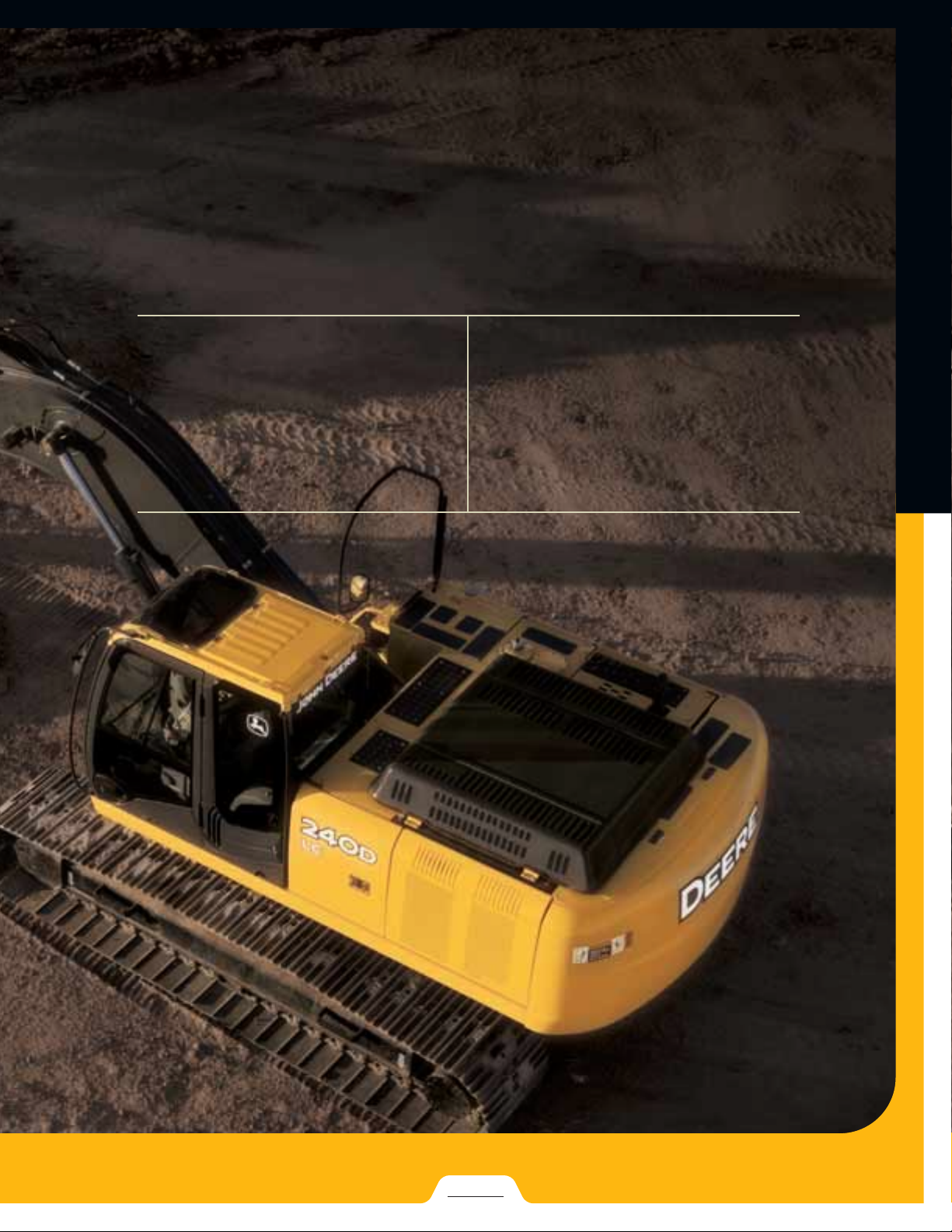
240D LC | 270D LC
24–27 METRIC TONS
EXCAVATORS
Page 2
Armed forces.
Armed forces.
Armed forces.
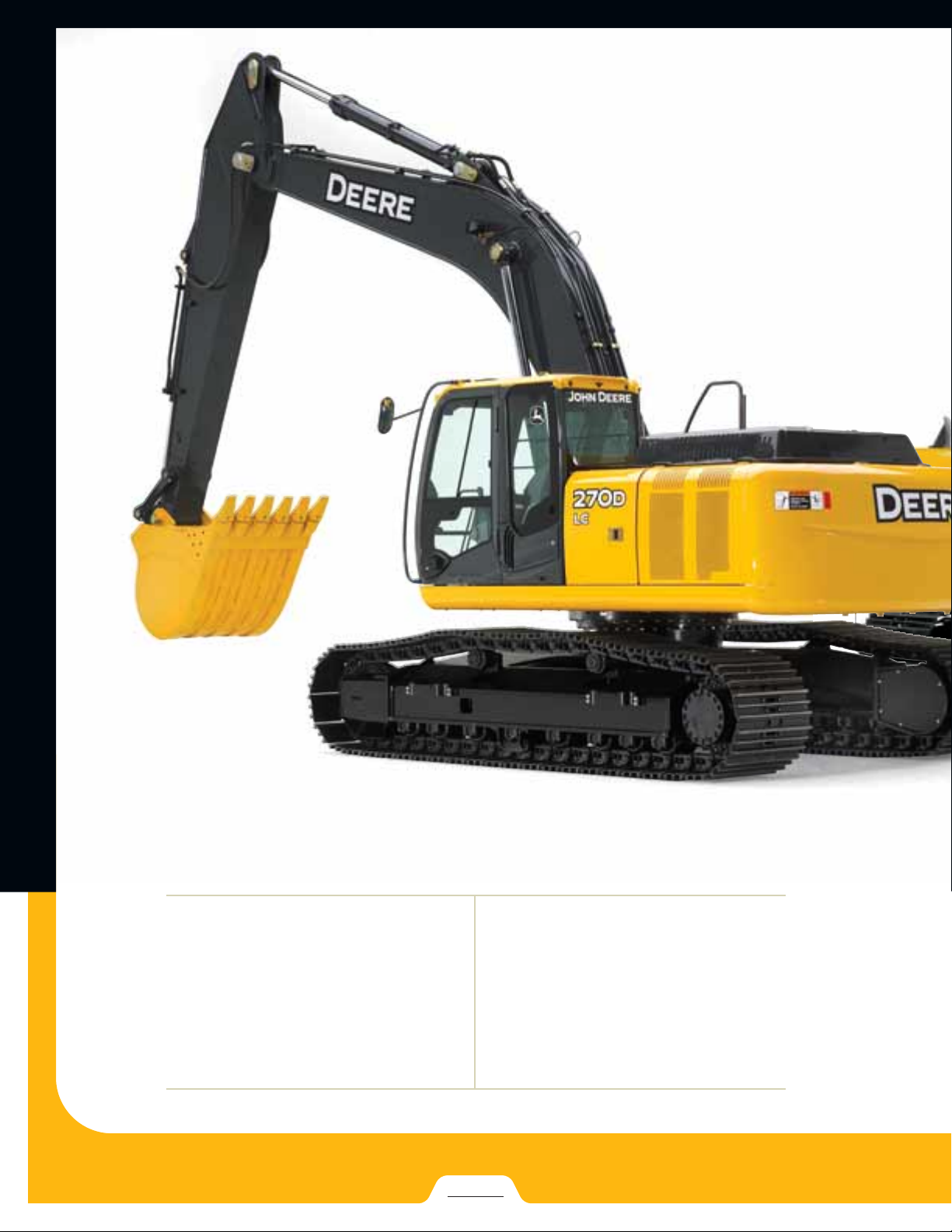
Bigger, stronger, faster, and quieter. The
new 240D LC and 270D LC are armed and
ready to take on your world. Both deliver
the power, smoothness, ease of operation,
and comfort you’d expect from John Deere
excavators — and then some. Each
features a rugged, fuel-effi cient Tier 3
PowerTech Plus
cooling system; and extended service
intervals for industry-leading uptime and
serviceability. And with other refi nements
such as faster hydraulics, better visibility,
and a roomier, more comfortable cab,
Deere once again sets the standard.
PAGES
2–3
™
engine; an enhanced
Page 3
Specifi cations 240D LC 270D LC
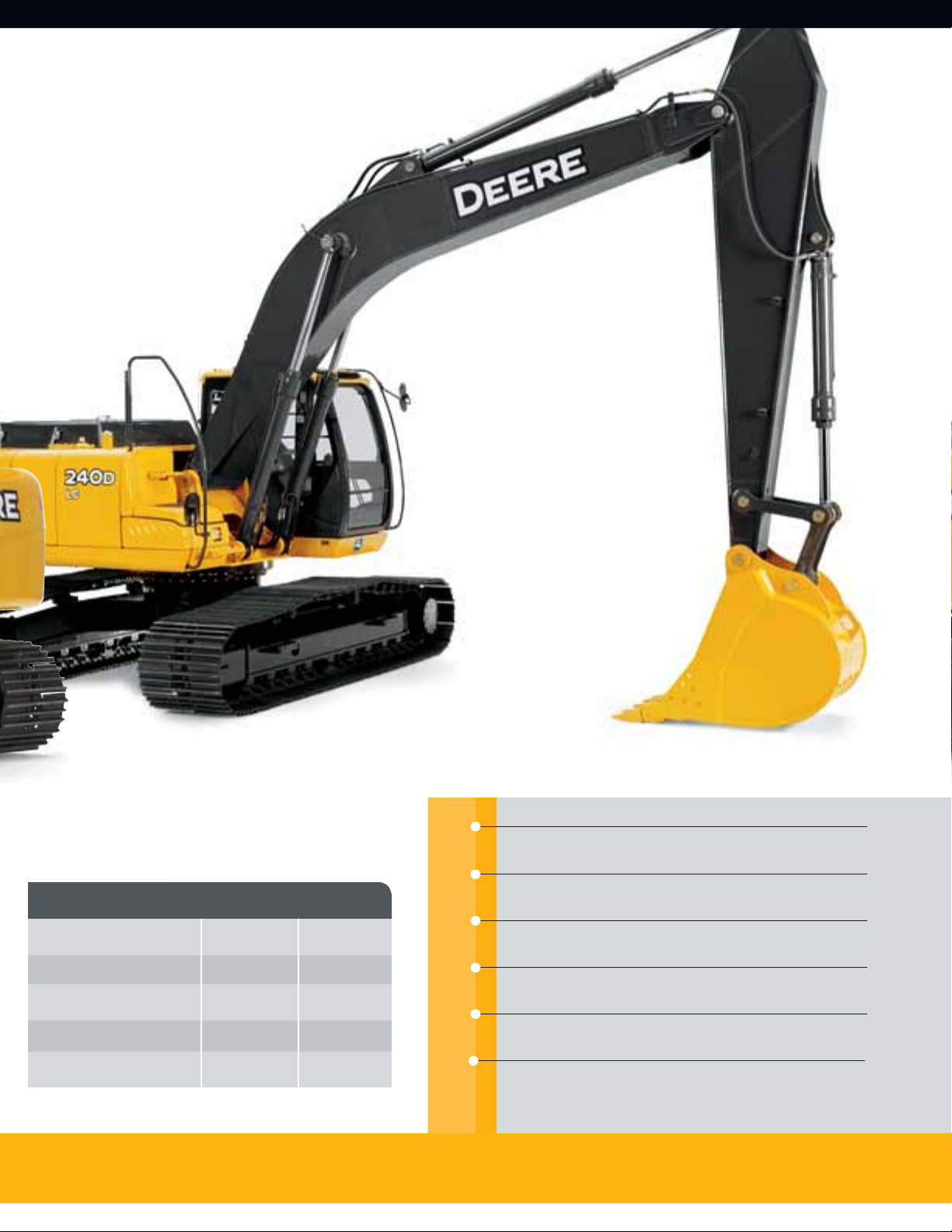
240D LC and 270D LC deliver more digging force, swing torque, and lift
capability, with less emissions and noise.
Extended engine and hydraulic oil service intervals increase uptime and
reduce daily operating costs.
Net Horsepower 177 hp 188 hp
Operating Weight 54,624 lb. 63,425 lb.
Lift Capacity 16,877 lb. 19,727 lb.
Digging Depth 24 ft. 7 in. 25 ft. 11 in.
Arm Breakout Force 24,020 lb. 25,979 lb.
Redesigned cab is more spacious and has 47-percent more glass for
best-in-class comfort and visibility.
Powerwise™ III engine /hydraulic management system maximizes power
output, saves fuel, and delivers smooth multifunction hydraulic operation.
Hydraulically driven, highly effi cient fan runs only as needed, reducing
noise, fuel consumption, and operating costs.
Tier 3 emission-certifi ed PowerTech Plus diesels deliver power without
compromise in all conditions.
Page 4
Electronically controlled variable-geometry turbocharger (VGT ) improves torque response, helping
match engine speed to load requirements.
Noise levels — and operator fatigue — have been
signifi cantly reduced. Variable-speed fan, dual-pass
muffl er, pilot-injected PowerTech Plus engine, and
isochronous high-idle speed help quiet things down.
Cooled exhaust gas recirculation ( EGR), four-valveper-cylinder head, and high-pressure commonrail fuel system enable the 6.8-L diesels to meet
Tier 3 emission standards without sacrifi cing
power or fuel effi ciency.
Additional hydraulic capability a necessity? Two
factory-installed high-pressure, high-fl ow auxiliary
hydraulic packages enable you to meet the need.
Choose from a variety of track widths, arm lengths,
buckets, and other options.
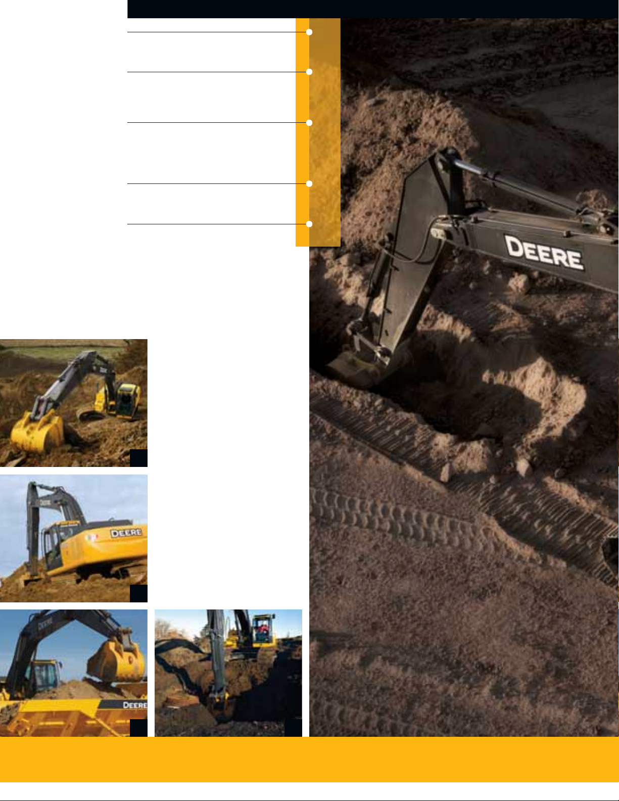
1. Powerwise III perfectly balances engine
performance and hydraulic fl ow for fast,
smooth, and predictable operation. One
work mode makes it easy to be productive
in any application.
1
2. Signifi cant increases in horsepower,
weight, dig force, and drawbar pull make
the D-Series highly productive machines
for a wide variety of work.
3. Increased fl ow, arm force, and swing
torque help speed cycles, enabling you to
load more trucks or open more trench.
4. For work that requires extra fi nesse, the
D-Series’ best-in-class metering and
smooth multifunction operation give you
the precise control you need.
2
3 4
Page 5
Quietly go about your
Quietly go about your
Quietly go about your
business of building
business of building
business of building
your bottom line.
your bottom line.
your bottom line.
D-Series Excavators speak softly and carry
a big stick. Combining strong digging forces
with outstanding lift capacity and reach,
the 240D LC and 270D LC are more than up
to any task. Faster hydraulics boost productivity, while increased drawbar pull and arm
force provide an additional lift to production.
The Powerwise III engine/hydraulic management system provides pinpoint metering and
low-effort control, while numerous noisereduction enhancements further reduce
operator fatigue. Add any of the many
available options, and put even more work
within reach.
PAGES
4–5
Page 6
See more, do more.
See more, do more.
See more, do more.
Yours aren’t just any employees. Why equip them
with just another excavator? To help make the
most of their skills, put your operators behind the
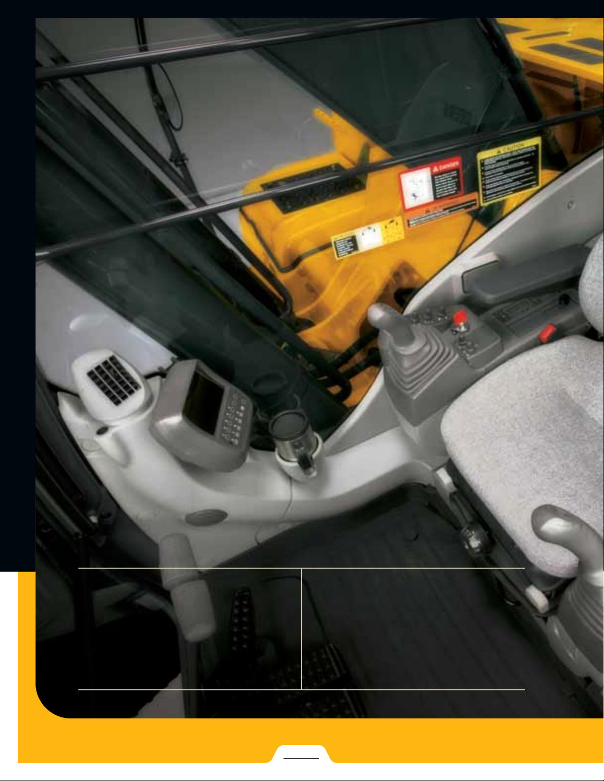
controls of a John Deere D-Series. Its spacious,
well-appointed interior boasts more of everything.
Forty-seven-percent more glass for virtually unrestricted visibility. Substantially more legroom.
And a bevy of creature comforts, including automatic climate control, AM/FM radio, generous
storage space, and available air-suspension
heated seat. But it’s not just the extras that
will make your operators more productive. They’ll
also benefi t from the things the D-Series deliver
less of — such as noise, fatigue, and emissions.
PAGES
6–7
Page 7

Deluxe-suspension multi-position seat has 10½ inches of
travel, sliding together or independently of the control console.
So it won’t cramp an operator’s style.
Ergonomically correct short-throw pilot levers provide smooth,
predictable fi ngertip control with less movement or effort.
Pushbuttons in the right lever allow fi ngertip control of auxiliary hydraulic fl ow for operating attachments.
Convenient 12-volt port powers cell phones and other
electronic devices.
Redesigned cab isn’t just roomier, it’s also noticeably quieter
and more comfortable. Silicone-fi lled mounts effectively
isolate operators from noise and vibration.
1. Wide expanse of glass, narrow front
cab posts, large overhead tinted hatch,
and numerous mirrors provide virtually
unobstructed all-around visibility.
2. No shortage of storage in here. There’s a
place for a cooler, cup holders, and even a
hot/cold box that keeps beverages at just
the right temperature.
3. Automatic, high-velocity bi-level climatecontrol system with automotive-style
adjustable louvers helps keep the glass
clear and the cab comfortable.
4. Intuitive, multi-language monitor provides
a wealth of machine info and control. Its
LCD four-color screen displays operating,
diagnostic, and maintenance data with
easy-on-the-eyes clarity.
1
2
4
3
Page 8

Graphite-iron wet-sleeve cylinder liners, monosteel pistons, and large-diameter connecting rods
ensure long-term engine durability.
Welded bulkheads within the boom resist torsional
stress. Reinforced D-channel side frames provide
maximum cab and component protection.
Tungsten-carbide coating creates an extremely
wear-resistant surface to protect the all-important
bucket-to-arm joint.
An optional reversing fan back-blows cooler cores
to reduce debris buildup. It’s a welcome addition
that will increase uptime.
Oil-impregnated bushings enhance durability and
extend grease intervals to 500 hours for the armand-boom joint and 100 hours for the bucket joint.
Booms, arms, and mainframes are so tough,
they’re warranted for three years or 10,000 hours.
1. Hydraulically driven cool-on-demand
fan runs only as needed, reducing fuel
consumption and debris fl ow through the
coolers. Highly effi cient system keeps
things cool, even in tough environments
or high altitudes.
1
2. Perforations in the hood and side shields
serve as a “fi rst fi lter,” helping prevent
trash entry. Anything that passes through
will also clear the eight-fi n-per-inch
cooler cores.
3. Reinforced resin thrust plates, grooved
bushings, and thermal-coated bucket
joints increase arm and boom lube intervals to 500 hours.
4. You won’t fi nd a more durable swing
bearing or mainframe on comparablesize excavators.
2
3 4
Page 9

Nothing runs like a
Nothing runs like a
Nothing runs like a
Deere because nothing
Deere because nothing
Deere because nothing
is built like one.
is built like one.
is built like one.
From their durable sealed and lubricated
undercarriages to their heavy-duty fuel-sipping
PowerTech Plus
the hilt to deliver unsurpassed reliability. These
plus numerous other traditional John Deere
features such as wet-sleeve engine liners,
engines, the D-Series are built to
PAGES
tungsten-carbide thermal-coated arm surfaces,
oil-impregnated bushings, welded-boom bulkheads, and extended engine and hydraulic oilchange intervals help keep downtime down and
profi ts up. When you know how they’re built,
you’ll run a Deere.
8–9
Page 10

Machine Information
Center (MIC) captures
and stores vital machine
performance and utilization data to help improve
uptime, productivity,
and profi t.
Auto-idle automatically
reduces engine speed
when hydraulics aren’t
in use, helping make the
most of every precious
drop of fuel.
Large easy-to-open
doors provide quick
access to service items.
Lube banks, fi l t e r s,
and checkpoints are
grouped for added
convenience.
Large fuel tanks and
500- and 5,000-hour
engine and hydraulic
oil-service intervals
increase uptime and
help lower daily
operating costs.
Fluid-level sight gauges
are conveniently located
and can be checked at
a glance.
Nobody backs you
better than the 500plus John Deere
dealers throughout
North America.
PAGES
10–11
Page 11

Minimize maintenance,
Minimize maintenance,
Minimize maintenance,
maximize results.
maximize results.
maximize results.
As with all John Deere machines, D-Series
Excavators are loaded with features that make
them hassle free to service and low cost to maintain. Large, easy-to-open service doors and easyto-reach daily service points make quick work
of the daily routine. Remote-mounted vertical
1. Vertical spin-on engine oil and fuel /water
fi l t e r s a r e positioned in the right rear compartment for simplifi ed servicing.
4. Coolers’ eight-fi n-per-inch spacing lets trash
easily pass to resist plugging. Hinged, swingout coolers provide added core access.
2. Ground-level fresh-air cab fi lter is quickly
serviced from outside the cab. Where it’s
more likely to get done.
5. Remote diagnostic and fl uid-sample ports
help speed preventative maintenance and
troubleshooting.
oil and fuel fi lters and extended engine and
hydraulic oil-change intervals minimize periodic
maintenance, too. Plus, the Machine Information
Center (MIC) and remote fl uid-sample ports help
you make timely decisions about machine upkeep, further minimizing downtime and expense.
3. Centralized lube banks place diffi cult-to-lube
zerks within easy reach. Help make greasing
less messy and time consuming, too.
6. Convenient door atop the hood speeds and
simplifi es daily engine oil and coolant checks.
1
4
2 3
5 6
Page 12

Specifications
Specifications
Specifications
Engine 240D LC
Type . . . . . . . . . . . . . . . . . . . . . . . . . . . . . . . . . . . John Deere 6068H with altitude-compensating turbocharger and air-to-air charge air cooler; certified to EPA Tier 3 emissions
Net Peak Power (ISO9249) . . . . . . . . . . . . . . . . . . 177 hp (132 kW) @ 2,000 rpm
Net Peak Torque (ISO9249) . . . . . . . . . . . . . . . . . . 576 lb.-ft. (781 Nm) @ 1,400 rpm
Cylinders . . . . . . . . . . . . . . . . . . . . . . . . . . . . . . . . 6
Displacement . . . . . . . . . . . . . . . . . . . . . . . . . . . . 414 cu. in. (6.8 L)
Cooling Fan . . . . . . . . . . . . . . . . . . . . . . . . . . . . . . suction-type, hydraulic-driven, remote-mounted drive
Electrical System. . . . . . . . . . . . . . . . . . . . . . . . . . 24 volt with 80-amp alternator
Batteries (two 12 volt) . . . . . . . . . . . . . . . . . . . . . . reserve capacity: 180 min.
Off-level capacity . . . . . . . . . . . . . . . . . . . . . . . . . 100% (45 deg.)
Hydraulic System
Main Pumps . . . . . . . . . . . . . . . . . . . . . . . . . . . . . two variable-displacement axial-piston
Maximum Flow . . . . . . . . . . . . . . . . . . . . . . . . 2 x 59.2 gpm (2 x 224 L/min.)
Pilot Pump. . . . . . . . . . . . . . . . . . . . . . . . . . . . . . . one gear
Maximum Flow . . . . . . . . . . . . . . . . . . . . . . . . 8.9 gpm (34 L/min.)
Pressure Setting . . . . . . . . . . . . . . . . . . . . . . . 580 psi (4000 kPa)
System Operating Pressure
Implement Circuits . . . . . . . . . . . . . . . . . . . . . 4,980 psi (34 300 kPa)
Tra vel Circuits . . . . . . . . . . . . . . . . . . . . . . . . . 4,980 psi (34 300 kPa)
Swing Circuits . . . . . . . . . . . . . . . . . . . . . . . . . 4,700 psi (32 400 kPa)
Power Boost . . . . . . . . . . . . . . . . . . . . . . . . . . 5,260 psi (36 300 kPa)
Oil Filtration. . . . . . . . . . . . . . . . . . . . . . . . . . . . . . one 10-micron full-flow return filter with by-pass / one pilot oil filter
Cylinders
Bore Rod Diameter Stroke
Boom (2) . . . . . . . . . . . . . . . . . . . . . . . . . . . . . . . . 4.9 in. (125 mm) 3.5 in. (90 mm) 54.7 in. (1390 mm)
Arm (1) . . . . . . . . . . . . . . . . . . . . . . . . . . . . . . . . . 5.5 in. (140 mm) 3.9 in. (100 mm) 63.4 in. (1610 mm)
Bucket (1) . . . . . . . . . . . . . . . . . . . . . . . . . . . . . . . 5.1 in. (130 mm) 3.5 in. (90 mm) 42.3 in. (1075 mm)
Swing Mechanism
Swing Speed . . . . . . . . . . . . . . . . . . . . . . . . . . . . . 0–13.5 rpm
Swing Torque . . . . . . . . . . . . . . . . . . . . . . . . . . . . 54,857 lb.-ft. (74 433 Nm)
Undercarriage
Carrier Rollers (per side) . . . . . . . . . . . . . . . . . . . . 2
Track Rollers (per side) . . . . . . . . . . . . . . . . . . . . . 9
Shoes, Triple Semi-Grouser (per side) . . . . . . . . . . 51
Track Guides . . . . . . . . . . . . . . . . . . . . . . . . . . . . . front and center
Track Adjustment. . . . . . . . . . . . . . . . . . . . . . . . . . hydraulic
Tra vel Speed
Low. . . . . . . . . . . . . . . . . . . . . . . . . . . . . . . . . 0–2.1 mph (0–3.4 km/h)
High . . . . . . . . . . . . . . . . . . . . . . . . . . . . . . . . 0–3.4 mph (0–5.5 km/h)
Drawbar Pull . . . . . . . . . . . . . . . . . . . . . . . . . . . . . 49,920 lb. (22 650 kg)
PAGES
12–13
Page 13

Ground Pressure Data 240D LC
E
GROUND LINE
B
C
D
F
G
CENTERLINE OF SWING
B'
A'
A
Average Ground Pressure
28-in. (700 mm) Triple Semi-Grouser Shoes
(recommended for rocky terrain/stumps) . . . 6.02 psi (41.5 kPa)
32-in. (800 mm) Triple Semi-Grouser Shoes
(recommended for general/soft terrain) . . . 5.34 psi (36.8 kPa)
Capacities (U.S.)
Fuel Tank. . . . . . . . . . . . . . . . . . . . . . . . . . . . . . . . 132 gal. (500 L)
Cooling System . . . . . . . . . . . . . . . . . . . . . . . . . . . 31.6 qt. (29.9 L)
Engine Lubrication, Including Filter . . . . . . . . . . . . 26 qt. (24.6 L)
Hydraulic Tank. . . . . . . . . . . . . . . . . . . . . . . . . . . . 39 gal. (147.6 L)
Hydraulic System . . . . . . . . . . . . . . . . . . . . . . . . . 63.4 gal. (240 L)
Propel Gearbox (each) . . . . . . . . . . . . . . . . . . . . . . 6.5 qt. (6.2 L)
Swing Drive. . . . . . . . . . . . . . . . . . . . . . . . . . . . . . 7.5 qt. (7 L)
SAE Operating Weights
With Full Fuel Tank; 175-lb. (79 kg) Operator;
1.38-cu.-yd. (1.06 m
2,195-lb. (996 kg) Bucket; 11-ft. 10-in.
(3.61 m) Arm; 11,904-lb. (5400 kg) Counterweight; and 32-in. (800 mm) Triple Semi-
Grouser Shoes. . . . . . . . . . . . . . . . . . . . . . . . . 54,654 lb. (24 791 kg)
3
), 42-in. (1065 mm),
Component Weights
Undercarriage
28-in. (700 mm) Triple Semi-Grouser Shoes. . . 18,650 lb. (8460 kg)
32-in. (800 mm) Triple Semi-Grouser Shoes. . . 19,277 lb. (8744 kg)
One-Piece Boom (with arm cylinder) . . . . . . . . . . . 4,868 lb. (2208 kg)
Arm with Bucket Cylinder and Linkage
9 ft. 9 in. (2.96 m) . . . . . . . . . . . . . . . . . . . . . . 2,855 lb. (1295 kg)
11 ft. 10 in. (3.61 m) . . . . . . . . . . . . . . . . . . . . 3,075 lb. (1395 kg)
Boom Lift Cylinders (2) Total Weight . . . . . . . . . . . 957 lb. (434 kg)
1.38-cu.-yd. (1.06 m
Heavy-Duty Plate-Lip Bucket. . . . . . . . . . . . . . 2,195 lb. (996 kg)
Counterweight. . . . . . . . . . . . . . . . . . . . . . . . . . . . 11,904 lb. (5400 kg)
3
), 42-in. (1065 mm)
Operating Information
Arm Force with 32-in. (800 mm) Triple Semi-
Grouser Shoes* . . . . . . . . . . . . . . . . . . . . . . . . 27,640 lb. (122.9 kN) 24,020 lb. (106.8 kN)
Bucket Digging Force with 32-in. (800 mm)
Triple Semi-Grouser Shoes* . . . . . . . . . . . . . . 37,670 lb. (167 kN) 37,670 lb. (167 kN)
Lifting Capacity Over Front @ Ground Level
20-ft. (6.1 m) Reach* . . . . . . . . . . . . . . . . . . . 17,721 lb. (8038 kg) 16,877 lb. (7655 kg)
A Maximum Reach . . . . . . . . . . . . . . . . . . . . . . 33 ft. 5 in. (10.19 m) 35 ft. 6 in. (10.81 m)
A' Maximum Reach @ Ground Level . . . . . . . . . 32 ft. 9 in. (9.99 m) 34 ft. 11 in. (10.64 m)
B Maximum Digging Depth . . . . . . . . . . . . . . . . 22 ft. 5 in. (6.84 m) 24 ft. 7 in. (7.49 m)
B' Maximum Digging Depth @ 8-ft. (2.44 m)
Flat Bottom . . . . . . . . . . . . . . . . . . . . . . . . . . 21 ft. 9 in. (6.63 m) 24 ft. 1 in. (7.33 m)
C Maximum Cutting Height . . . . . . . . . . . . . . . . 33 ft. 2 in. (10.12 m) 34 ft. 6 in. (10.52 m)
D Maximum Dumping Height . . . . . . . . . . . . . . 23 ft. 6 in. (7.16 m) 24 ft. 9 in. (7.54 m)
E Minimum Swing Radius . . . . . . . . . . . . . . . . . 11 ft. 3 in. (3.44 m) 11 ft. 4 in. (3.46 m)
F Maximum Vertical Wall. . . . . . . . . . . . . . . . . . 19 ft. 5 in. (5.91 m) 21 ft. 9 in. (6.63 m)
G Tail Swing Radius . . . . . . . . . . . . . . . . . . . . . 9 ft. 8 in. (2.94 m) 9 ft. 8 in. (2.94 m)
*Digging forces and lift capacities with power boost.
Arm Length Arm Length
9 ft. 9 in. (2.96 m) 11 ft. 10 in. (3.61 m)
Page 14

9 ft. 6 in. (2.89 m)
1 ft. 6 in. (460 mm)
32 in. (800 mm)
15 ft. 3 in. (4.64 m)
12 ft. 7 in. (3.84 m)
3 ft. 7 in. (1090 mm)
9 ft. 8 in. (2.94 m)
8 ft. 6 in. (2.59 m)
9 ft. 11 in. (3.02 m)
28 in. (700 mm)
11 ft. 1 in. (3.39 m)
B
A
Dimensions
9-ft. 9-in. (2.96 m) arm . . . . . . . . . . . . . . . . . . 10 ft. 1 in. (3.07 m)
A
240D LC
11-ft. 10-in. (3.61 m) arm . . . . . . . . . . . . . . . . 10 ft. 4 in. (3.14 m)
B 9-ft. 9-in. (2.96 m) arm . . . . . . . . . . . . . . . . . . 33 ft. 4 in. (10.15 m)
11-ft. 10-in. (3.61 m) arm . . . . . . . . . . . . . . . . 33 ft. 6 in. (10.21 m)
Lift Capacities
Boldface italic
1.38-cu.-yd. (1.06 m
Total load includes weight of cables, hook, etc. Figures do not exceed 87 percent of hydraulic capacities or 75 percent of weight needed to tip machine. All lift capacities are
based on SAE J1097.
Load Point 10 ft. (3.05 m) 15 ft. (4.57 m) 20 ft. (6.10 m) 25 ft. (7.62 m) 30 ft. (9.15 m)
Height Over Front Over Side Over Front Over Side Over Front Over Side Over Front Over Side Over Front Over Side
With 11-ft. 10-in. (3.61 m) arm and 32-in. (800 mm) triple semi-grouser shoes
20 ft. (6.10 m)
15 ft. (4.57 m)
10 ft. (3.05 m)
5 ft. (1.52 m)
Ground Line
–5 ft. (–1.52 m)
–10 ft. (–3.05 m)
–15 ft. (–4.57 m)
–20 ft. (–6.10 m)
With 11-ft. 10-in. (3.61 m) arm and 28-in. (700 mm) triple semi-grouser shoes
20 ft. (6.10 m)
15 ft. (4.57 m)
10 ft. (3.05 m)
5 ft. (1.52 m)
Ground Line
–5 ft. (–1.52 m)
–10 ft. (–3.05 m)
–15 ft. (–4.57 m)
–20 ft. (–6.10 m)
With 9-ft. 9-in. (2.96 m) arm and 32-in. (800 mm) triple semi-grouser shoes
20 ft. (6.10 m)
15 ft. (4.57 m)
10 ft. (3.05 m)
5 ft. (1.52 m)
Ground Line
–5 ft. (–1.52 m)
–10 ft. (–3.05 m)
–15 ft. (–4.57 m)
type indicates hydraulic-limited capacities; lightface type indicates stability-limited capacities, in lb. (kg). Ratings at bucket lift hook; machine equipped with
3
), 42-in. (1065 mm), 2,195-lb. (996 kg) bucket; 11,904-lb. (5400 kg) counterweight; standard gauge; and situated on firm, uniform supporting surface.
7,549 (3424) 7,549 (3424)
8,518 (3864) 8,518 (3864) 8,607 (3904) 8,607 (3904) 6,261 (2840) 6,261 (2840)
14,688 (6662) 14,688 (6662) 11,557 (5242) 11,557 (5242) 10,049 (4558)
20,756 (9415)
24,563 (11 142)
13,061 (5924) 13,061 (5924) 25,705 (11 660)
22,506 (10 209) 22,506 (10 209) 25,004 (11 342)
29,633 (13 441) 29,633 (13 441) 22,540 (10 224)
17,275 (7836) 17,275 (7836) 12,097 (5487)
18,889 (8568)
17,619 (7992)
17,163 (7785) 17,903 (8121) 10,923 (4955) 12,480 (5661) 7,678 (3483) 9,308 (4222) 5,670 (2572)
17,154 (7781) 17,768 (8060) 10,804 (4901) 12,387 (5619) 7,593 (3444)
17,460 (7920)
14,486 (6571)
16,877 (7655)
16,709 (7579)
12,098 (5488)
11,347 (5147) 12,785 (5799) 7,956 (3609) 9,457 (4290) 5,809 (2635)
10,961 (4972)
11,532 (5231)
11,624 (5273)
12,307 (5582)
8,879 (4027)
8,385 (3803)
7,768 (3524)
8,091 (3670)
9,678 (4390)
6,289 (2853)
6,038 (2739)
7,549 (3424) 7,549 (3424)
8,518 (3864) 8,518 (3864) 8,607 (3904) 8,607 (3904) 6,261 (2840) 6,261 (2840)
14,688 (6662) 14,688 (6662) 11,557 (5242) 11,557 (5242) 10,049 (4558)
20,756 (9415)
24,563 (11 142)
13,061 (5924) 13,061 (5924) 25,705 (11 660)
22,506 (10 209) 22,506 (10 209) 25,004 (11 342)
29,633 (13 441) 29,633 (13 441) 22,540 (10 224)
17,275 (7836) 17,275 (7836) 12,097 (5487)
18,696 (8480)
17,417 (7900)
16,960 (7693) 17,687 (8023) 10,786 (4892) 12,322 (5589) 7,574 (3436) 9,183 (4165) 5,587 (2534)
16,952 (7689) 17,551 (7961) 10,666 (4838) 12,229 (5547) 7,489 (3397)
17,257 (7828)
14,486 (6571)
16,877 (7655)
16,709 (7579)
11,961 (5425)
11,210 (5085) 12,627 (5728) 7,853 (3562) 9,332 (4233) 5,726 (2597)
10,824 (4910)
11,395 (5169)
11,624 (5273)
12,307 (5582)
8,775 (3980)
8,282 (3757) 9,578 (4345) 5,955 (2701)
7,664 (3476)
8,091 (3670)
6,206 (2815)
8,237 (3736) 8,237 (3736)
17,515 (7945) 17,515 (7945) 13,047 (5918)
23,155 (10 503)
25,634 (11 628)
12,761 (5788) 12,761 (5788) 25,654 (11 637)
19,352 (8778) 19,352 (8778) 24,124 (10 943)
27,603 (12 521) 27,603 (12 521) 20,730 (9403)
10,540 (4781) 10,540 (4781) 9,885 (4484)
12,726 (5772)
18,262 (8284)
17,416 (7900)
17,248 (7824) 17,922 (8129) 10,954 (4969) 12,530 (5684) 7,734 (3508)
17,398 (7892) 17,921 (8129) 10,953 (4968) 12,548 (5692) 7,750 (3515)
17,836 (8090)
15,755 (7146)
17,721 (8038)
15,487 (7025)
11,858 (5379)
11,241 (5099) 12,744 (5781) 7,930 (3597)
11,247 (5102)
11,074 (5023)
12,482 (5662)
9,122 (4138)
8,728 (3959)
8,288 (3759)
7,205 (3268)
9,206 (4176)
9,235 (4189)
6,196 (2810)
6,004 (2723)
5,837 (2648)
PAGES
14–15
Page 15

Lift Capacities
4.0
(3.0)
3.0
(2.3)
2.0
(1.5)
2,000 2,200 2,600 3,200
lb./cu. yd.
kg/m
3
BUCKET SIZE cu. yd. (m
3
)
1,600 3,400
1.0
(0.8)
1.5
(1.0)
2.5
(1.9)
3.5
(2.7)
1,200 1,400 1,800 2,400 2,800 3,000 3,600
Wet Peat
Topsoil
Coal
Caliche
Shale
Dry Sand
Dry Clay
Limestone
Wet Earth
Wet Clay, Granite
Moist Sand
Wet Sand
Wet Sand, Gravel
1300
Contact your John Deere dealer for optimum bucket and attachment selections. These recommendations are for general conditions and average use. Does not include optional
equipment such as thumbs or couplers. Larger buckets may be possible when using light materials, for flat and level operations, less compacted materials, and volume loading
applications such as mass excavation applications in ideal conditions. Smaller buckets are recommended for adverse conditions such as off-level applications, rocks, and uneven
surfaces. Bucket capacity indicated is SAE heaped.
*
700 800 900 1000 1100 1200
2000
1400 1500 1600 1700 1800 1900
2100
Deere 9-ft. 9-in. (2.96 m) Arm
Deere 11-ft. 10-in. (3.61 m) Arm
Boldface italic
1.38-cu.-yd. (1.06 m
(continued)
type indicates hydraulic-limited capacities; lightface type indicates stability-limited capacities, in lb. (kg). Ratings at bucket lift hook; machine equipped with
3
), 42-in. (1065 mm), 2,195-lb. (996 kg) bucket; 11,904-lb. (5400 kg) counterweight; standard gauge; and situated on firm, uniform supporting surface.
240D LC
Total load includes weight of cables, hook, etc. Figures do not exceed 87 percent of hydraulic capacities or 75 percent of weight needed to tip machine. All lift capacities are
based on SAE J1097.
Load Point 10 ft. (3.05 m) 15 ft. (4.57 m) 20 ft. (6.10 m) 25 ft. (7.62 m) 30 ft. (9.15 m)
Height Over Front Over Side Over Front Over Side Over Front Over Side Over Front Over Side Over Front Over Side
With 9-ft. 9-in. (2.96 m) arm and 28-in. (700 mm) triple semi-grouser shoes
20 ft. (6.10 m)
15 ft. (4.57 m)
10 ft. (3.05 m)
5 ft. (1.52 m)
Ground Line
–5 ft. (–1.52 m)
–10 ft. (–3.05 m)
–15 ft. (–4.57 m)
17,515 (7945) 17,515 (7945) 13,047 (5918)
23,155 (10 503)
25,634 (11 628)
12,761 (5788) 12,761 (5788) 25,654 (11 637)
19,352 (8778) 19,352 (8778) 24,124 (10 943)
27,603 (12 521) 27,603 (12 521) 20,730 (9403)
10,540 (4781) 10,540 (4781) 9,885 (4484)
12,589 (5710)
18,059 (8192)
17,213 (7808)
15,755 (7146)
17,721 (8038)
11,721 (5317)
11,104 (5037) 12,586 (5709) 7,826 (3550)
17,045 (7732) 17,706 (8031) 10,817 (4907) 12,372 (5612) 7,630 (3461)
17,196 (7800) 17,705 (8031) 10,816 (4906) 12,389 (5620) 7,646 (3468)
17,634 (7999)
15,487 (7025)
11,110 (5039)
8,237 (3736) 8,237 (3736)
9,018 (4091)
11,074 (5023)
12,482 (5662)
8,625 (3912)
8,184 (3712)
7,205 (3268)
9,206 (4176)
9,235 (4189)
6,113 (2773)
5,921 (2686)
5,753 (2610)
Buckets
A full line of buckets is offered to meet a wide variety of applications. Digging forces are with power boost. Tooth selection includes either the John Deere Fanggs®, Standard,
Tiger, Twin Tiger, Abrasion panel, or Flare tooth, or the ESCO (Vertalok) Standard, Tiger, Twin Tiger, or Flare tooth. Replaceable cutting edges are available through John Deere
parts. Optional side cutters add 6 inches (150 mm) to bucket widths.
Bucket Bucket Bucket Arm Dig Force Arm Dig Force Bucket
Type Bucket Width Capacity* Weight Dig Force 9 ft. 9 in. (2.96 m) 11 ft. 10 in. (3.61 m) Tip Radius No. Teeth
in. mm cu. yd. m
3
lb. kg lb. kN lb. kN lb. kN in. mm
Heavy-Duty 42 1065 1.38 1.06 2,195 996 37,676 167.0 27,640 122.9 24,020 106.8 56.5 1435 5
Plate Lip 48 1220 1.60 1.22 2,359 1070 37,676 167.0 27,640 122.9 24,020 106.8 56.5 1435 6
54 1370 1.82 1.39 2,507 1137 37,676 167.0 27,640 122.9 24,020 106.8 56.5 1435 6
Heavy-Duty 24 610 0.92 0.70 1,765 801 35,846 159.4 26,710 118.8 23,313 103.7 62.5 1588 3
High Capacity 30 760 1.20 0.92 2,010 912 35,846 159.4 26,710 118.8 23,313 103.7 62.5 1588 4
36 915 1.48 1.13 2,133 968 35,846 159.4 26,710 118.8 23,313 103.7 62.5 1588 4
42 1065 1.75 1.34 2,279 1034 35,846 159.4 26,710 118.8 23,313 103.7 62.5 1588 5
48 1200 2.03 1.55 2,505 1136 35,846 159.4 26,710 118.8 23,313 103.7 62.5 1588 6
Severe-Duty 30 760 0.95 0.73 2,080 943 37,676 167.0 27,640 122.9 24,020 106.8 56.5 1435 4
Plate Lip 36 915 1.16 0.89 2,179 988 37,676 167.0 27,640 122.9 24,020 106.8 56.5 1435 4
42 1065 1.38 1.06 2,345 1064 37,676 167.0 27,640 122.9 24,020 106.8 56.5 1435 5
Ditching 60 1525 1.34 1.02 1,562 709 45,273 201.4 29,244 130.1 25,225 112.2 47.0 1194 0
*All capacities are SAE heaped ratings and with side cutters.
Bucket Selection Guide*
Page 16

Specifications
Specifications
Specifications
Engine 270D LC
Type . . . . . . . . . . . . . . . . . . . . . . . . . . . . . . . . . . . John Deere 6068H with altitude-compensating turbocharger and air-to-air charge air cooler; certified to EPA Tier 3 emissions
Net Peak Power (ISO9249) . . . . . . . . . . . . . . . . . . 188 hp (140 kW) @ 2,100 rpm
Net Peak Torque (ISO9249) . . . . . . . . . . . . . . . . . . 599 lb.-ft. (813 Nm) @ 1,400 rpm
Cylinders . . . . . . . . . . . . . . . . . . . . . . . . . . . . . . . . 6
Displacement . . . . . . . . . . . . . . . . . . . . . . . . . . . . 414 cu. in. (6.8 L)
Cooling Fan . . . . . . . . . . . . . . . . . . . . . . . . . . . . . . suction-type, hydraulic-driven, remote-mounted drive
Electrical System. . . . . . . . . . . . . . . . . . . . . . . . . . 24 volt with 80-amp alternator
Batteries (two 12 volt) . . . . . . . . . . . . . . . . . . . . . . reserve capacity: 180 min.
Off-level capacity . . . . . . . . . . . . . . . . . . . . . . . . . 100% (45 deg.)
Hydraulic System
Main Pumps . . . . . . . . . . . . . . . . . . . . . . . . . . . . . two variable-displacement axial-piston
Maximum Flow . . . . . . . . . . . . . . . . . . . . . . . . 2 x 62.3 gpm (2 x 236 L/min.)
Pilot Pump. . . . . . . . . . . . . . . . . . . . . . . . . . . . . . . one gear
Maximum Flow . . . . . . . . . . . . . . . . . . . . . . . . 8.9 gpm (34 L/min.)
Pressure Setting . . . . . . . . . . . . . . . . . . . . . . . 580 psi (4000 kPa)
System Operating Pressure
Implement Circuits . . . . . . . . . . . . . . . . . . . . . 4,980 psi (34 300 kPa)
Tra vel Circuits . . . . . . . . . . . . . . . . . . . . . . . . . 4,980 psi (34 300 kPa)
Swing Circuits . . . . . . . . . . . . . . . . . . . . . . . . . 4,700 psi (32 400 kPa)
Power Boost . . . . . . . . . . . . . . . . . . . . . . . . . . 5,260 psi (36 300 kPa)
Oil Filtration. . . . . . . . . . . . . . . . . . . . . . . . . . . . . . one 10-micron full-flow return filter with by-pass / one pilot oil filter
Cylinders
Bore Rod Diameter Stroke
Boom (2) . . . . . . . . . . . . . . . . . . . . . . . . . . . . . . . . 5.3 in. (135 mm) 3.7 in. (95 mm) 53.5 in. (1360 mm)
Arm (1) . . . . . . . . . . . . . . . . . . . . . . . . . . . . . . . . . 5.9 in. (150 mm) 4.1 in. (105 mm) 65.3 in. (1659 mm)
Bucket (1) . . . . . . . . . . . . . . . . . . . . . . . . . . . . . . . 5.3 in. (135 mm) 3.5 in. (90 mm) 42.1 in. (1070 mm)
Swing Mechanism
Swing Speed . . . . . . . . . . . . . . . . . . . . . . . . . . . . . 0–12.6 rpm
Swing Torque . . . . . . . . . . . . . . . . . . . . . . . . . . . . 56,852 lb.-ft. (77 140 Nm)
Undercarriage
Carrier Rollers (per side) . . . . . . . . . . . . . . . . . . . . 2
Track Rollers (per side) . . . . . . . . . . . . . . . . . . . . . 8
Shoes, Triple Semi-Grouser (per side) . . . . . . . . . . 4
Track Guides . . . . . . . . . . . . . . . . . . . . . . . . . . . . . front and center
Track Adjustment. . . . . . . . . . . . . . . . . . . . . . . . . . hydraulic
Tra vel Speed
Low. . . . . . . . . . . . . . . . . . . . . . . . . . . . . . . . . 0–2.1 mph (0–3.3 km/h)
High . . . . . . . . . . . . . . . . . . . . . . . . . . . . . . . . 0–3.4 mph (0–5.5 km/h)
Drawbar Pull . . . . . . . . . . . . . . . . . . . . . . . . . . . . . 56,074 lb. (25 435 kg)
8
PAGES
16–17
Page 17

Ground Pressure Data 270D LC
E
GROUND LINE
B
C
D
F
G
CENTERLINE OF SWING
B'
A'
A
Average Ground Pressure
32-in. (800 mm) Triple Semi-Grouser Shoes
(recommended for general/soft terrain) . . . 5.84 psi (40.3 kPa)
Capacities (U.S.)
Fuel Tank. . . . . . . . . . . . . . . . . . . . . . . . . . . . . . . . 132 gal. (500 L)
Cooling System . . . . . . . . . . . . . . . . . . . . . . . . . . . 31.6 qt. (29.9 L)
Engine Lubrication, Including Filter . . . . . . . . . . . . 26 qt. (24.6 L)
Hydraulic Tank. . . . . . . . . . . . . . . . . . . . . . . . . . . . 39 gal. (148 L)
Hydraulic System . . . . . . . . . . . . . . . . . . . . . . . . . 63.4 gal. (240 L)
Propel Gearbox (each) . . . . . . . . . . . . . . . . . . . . . . 9 qt. (8.5 L)
Swing Drive. . . . . . . . . . . . . . . . . . . . . . . . . . . . . . 8 qt. (7.6 L)
SAE Operating Weights
With Full Fuel Tank; 175-lb. (79 kg) Operator;
1.75-cu.-yd. (1.34 m
2,279-lb. (1034 kg) Bucket; 12-ft. 4-in.
(3.75 m) Arm; 13,447-lb. (6100 kg) Counterweight; and 32-in. (800 mm) Triple Semi-
Grouser Shoes. . . . . . . . . . . . . . . . . . . . . . . . . 63,425 lb. (28 770 kg)
3
), 42-in. (1065 mm),
Component Weights
Undercarriage
32-in. (800 mm) Triple Semi-Grouser Shoes. . . 25,937 lb. (11 765 kg)
One-Piece Boom (with arm cylinder) . . . . . . . . . . . 5,086 lb. (2307 kg)
Arm with Bucket Cylinder and Linkage
10 ft. 2 in. (3.11 m) . . . . . . . . . . . . . . . . . . . . . 3,102 lb. (1407 kg)
12 ft. 4 in. (3.75 m) . . . . . . . . . . . . . . . . . . . . . 3,298 lb. (1496 kg)
Boom Lift Cylinders (2) Total Weight . . . . . . . . . . . 1,098 lb. (494 kg)
1.75-cu.-yd. (1.34 m
Heavy-Duty High-Capacity Bucket . . . . . . . . . . 2,279 lb. (1034 kg)
Counterweight. . . . . . . . . . . . . . . . . . . . . . . . . . . . 13,447 lb. (6100 kg)
3
), 42-in. (1065 mm)
Operating Information
Arm Force with 32-in. (800 mm) Triple Semi-
Grouser Shoes* . . . . . . . . . . . . . . . . . . . . . . . . 29,518 lb. (131.3 kN) 25,979 lb. (115.55 kN)
Bucket Digging Force with 32-in. (800 mm)
Triple Semi-Grouser Shoes* . . . . . . . . . . . . . . 37,480 lb. (166.7 kN) 37,480 lb. (166.7 kN)
Lifting Capacity Over Front @ Ground Level
20-ft. (6.1 m) Reach* . . . . . . . . . . . . . . . . . . . 20,773 lb. (9423 kg) 19,727 lb. (8948 kg)
A Maximum Reach . . . . . . . . . . . . . . . . . . . . . . 35 ft. 3 in. (10.74 m) 37 ft. 1 in. (11.30 m)
A' Maximum Reach @ Ground Level . . . . . . . . . 34 ft.7 in. (10.55 m) 36 ft. 6 in. (11.12 m)
B Maximum Digging Depth . . . . . . . . . . . . . . . . 23 ft. 10 in. (7.26 m) 25 ft. 11 in. (7.91 m)
B' Maximum Digging Depth @ 8-ft. (2.44 m)
Flat Bottom . . . . . . . . . . . . . . . . . . . . . . . . . . 23 ft. 2 in. (7.05 m) 25 ft. 8 in. (7.72 m)
C Maximum Cutting Height . . . . . . . . . . . . . . . . 32 ft. 10 in. (10.01 m) 34 ft. 4 in. (10.46 m)
D Maximum Dumping Height . . . . . . . . . . . . . . 23 ft. 2 in. (7.07 m) 24 ft. 7 in. (7.49 m)
E Minimum Swing Radius . . . . . . . . . . . . . . . . . 13 ft. 7 in. (4.41 m) 12 ft. 9 in. (3.89 m)
F Maximum Vertical Wall. . . . . . . . . . . . . . . . . . 20 ft. 1 in. (6.11 m) 23 ft. 1 in. (7.03 m)
G Tail Swing Radius . . . . . . . . . . . . . . . . . . . . . 9 ft. 8 in. (2.94 m) 9 ft. 8 in. (2.94 m)
*Digging forces and lift capacities with power boost.
Arm Length Arm Length
10 ft. 2 in. (3.11 m) 12 ft. 4 in. (3.75 m)
Page 18

Dimensions
9 ft. 6 in. (2.89 m)
1 ft. 8 in. (510 mm)
32 in. (800 mm)
10 ft. 2 in. (3.10 m)
16 ft. 2 in. (4.94 m)
13 ft. 3 in. (4.05 m)
3 ft. 10 in. (1180 mm)
9 ft. 8 in. (2.94 m)
11 ft. 1 in. (3.39 m)
8 ft. 6 in. (2.59 m)
B
A
10-ft. 2-in. (3.11 m) arm . . . . . . . . . . . . . . . . . 10 ft. 5 in. (3.17 m)
A
270D LC
12-ft. 4-in. (3.75 m) arm . . . . . . . . . . . . . . . . . 11 ft. 0 in. (3.35 m)
B 10-ft. 2-in. (3.11 m) arm . . . . . . . . . . . . . . . . . 33 ft. 11 in. (10.34 m)
12-ft. 4-in. (3.75 m) arm . . . . . . . . . . . . . . . . . 35 ft. 3 in. (10.74 m)
Lift Capacities
Boldface italic
1.75-cu.-yd. (1.34 m
Total load includes weight of cables, hook, etc. Figures do not exceed 87 percent of hydraulic capacities or 75 percent of weight needed to tip machine. All lift capacities are
based on SAE J1097.
Load Point 10 ft. (3.05 m) 15 ft. (4.57 m) 20 ft. (6.10 m) 25 ft. (7.62 m) 30 ft. (9.15 m)
Height Over Front Over Side Over Front Over Side Over Front Over Side Over Front Over Side Over Front Over Side
With 12-ft. 4-in. (3.75 m) arm and 32-in. (800 mm) triple semi-grouser shoes
25 ft. (7.62 m)
20 ft. (6.10 m)
15 ft. (4.57 m)
10 ft. (3.05 m)
5 ft. (1.52 m)
Ground Line
–5 ft. (–1.52 m)
–10 ft. (–3.05 m)
–15 ft. (–4.57 m)
–20 ft. (–6.10 m)
type indicates hydraulic-limited capacities; lightface type indicates stability-limited capacities, in lb. (kg). Ratings at bucket lift hook; machine equipped with
3
), 42-in. (1065 mm), 2,279-lb. (1034 kg) bucket; 13,447-lb. (6100 kg) counterweight; standard gauge; and situated on firm, uniform supporting surface.
8,490 (3851) 8,490 (3851)
8,629 (3914) 8,629 (3914) 5,984 (2714) 5,984 (2714)
17,039 (7729) 17,039 (7729) 13,189 (5982) 13,189 (5982) 11,405 (5173)
24,377 (11 057)
28,866 (13 094)
15,885 (7205) 15,885 (7205) 30,355 (13 769)
22,504 (10 208) 22,504 (10 208) 29,877 (13 552)
30,876 (14 005) 30,876 (14 005) 27,577 (12 509)
30,941 (14 035) 30,941 (14 035) 22,517 (10 214)
22,290 (10 111)
20,936 (9497)
20,481 (9290)
20,489 (9294)
20,821 (9444)
21,537 (9769)
16,795 (7618)
19,727 (8948)
21,412 (9712)
21,738 (9860)
20,489 (9294)
16,452 (7463)
9,676 (4389) 9,676 (4389) 9,609 (4359)
10,668 (4839)
14,398 (6531)
13,562 (6152)
13,102 (5943) 16,083 (7295) 9,284 (4211) 12,055 (5468) 6,922 (3140)
12,972 (5884) 15,965 (7242) 9,178 (4163)
13,131 (5956)
13,673 (6202)
13,401 (6079)
15,195 (6892)
15,518 (7039)
10,091 (4577)
9,601 (4355) 12,245 (5554) 7,096 (3219)
9,328 (4231)
10,524 (4774)
11,626 (5274)
10,392 (4714)
7,937 (3600)
7,680 (3484)
7,371 (3343)
6,920 (3139)
With 10-ft. 2-in. (3.11 m) arm and 32-in. (800 mm) triple semi-grouser shoes
20 ft. (6.10 m)
15 ft. (4.57 m)
10 ft. (3.05 m)
5 ft. (1.52 m)
Ground Line
–5 ft. (–1.52 m)
–10 ft. (–3.05 m)
–15 ft. (–4.57 m)
14,458 (6558) 14,458 (6558) 30,272 (13 731)
23,292 (10 565) 23,292 (10 565) 29,066 (13 184)
29,503 (13 382) 29,503 (13 382) 25,803 (11 704)
20,484 (9291) 20,484 (9291) 14,959 (6785) 14,959 (6785) 12,603 (5717)
27,306 (12 386)
28,596 (12 971)
21,575 (9786)
20,733 (9404)
20,588 (9339)
20,762 (9418)
21,225 (9628)
10,107 (4585) 10,107 (4585)
11,760 (5334) 11,760 (5334) 10,993 (4986)
18,319 (8309)
20,773 (9423)
21,875 (9922)
21,566 (9782)
19,419 (8808)
PAGES
18–19
14,121 (6405)
13,441 (6097)
13,133 (5957) 16,127 (7315) 9,337 (4235) 12,156 (5514) 7,026 (3187)
13,130 (5956) 16,121 (7312) 9,332 (4233)
13,422 (6088)
14,426 (6544)
15,959 (7239)
10,981 (4981)
10,494 (4760)
9,976 (4525)
9,564 (4338) 12,256 (5559) 7,117 (3228)
8,349 (3787)
11,531 (5230)
12,445 (5645)
7,778 (3528)
7,587 (3441)
7,332 (3326)
Page 19

Buckets 270D LC
4.0
(3.0)
3.0
(2.3)
2.0
(1.5)
2,000 2,200 2,600 3,200
lb./cu. yd.
kg/m
3
BUCKET SIZE cu. yd. (m
3
)
1,600
5.0
(3.8)
3,400
1.0
(0.8)
1.5
(1.0)
2.5
(1.9)
3.5
(2.7)
4.5
(3.4)
1,200 1,400 1,800 2,400 2,800 3,000 3,600
1300
700 800 900 1000 1100 1200
2000
1400 1500 1600 1700 1800 1900
2100
Wet Peat
Topsoil
Coal
Caliche
Shale
Dry Sand
Dry Clay
Limestone
Wet Earth
Wet Clay, Granite
Moist Sand
Wet Sand
Wet Sand, Gravel
Contact your John Deere dealer for optimum bucket and attachment selections. These recommendations are for general conditions and average use. Does not include optional
equipment such as thumbs or couplers. Larger buckets may be possible when using light materials, for flat and level operations, less compacted materials, and volume loading
applications such as mass excavation applications in ideal conditions. Smaller buckets are recommended for adverse conditions such as off-level applications, rocks, and uneven
surfaces. Bucket capacity indicated is SAE heaped.
*
Deere 12-ft. 4-in. (3.75 m) Arm
Deere 10-ft. 2-in. (3.11 m) Arm
A full line of buckets is offered to meet a wide variety of applications. Digging forces are with power boost. Tooth selection includes either the John Deere Fanggs®, Standard,
Tiger, Twin Tiger, Abrasion panel, or Flare tooth, or the ESCO (Vertalok) Standard, Tiger, Twin Tiger, or Flare tooth. Replaceable cutting edges are available through John Deere
parts. Optional side cutters add 6 inches (150 mm) to bucket widths.
Bucket Bucket Bucket Arm Dig Force Arm Dig Force Bucket
Type Bucket Width Capacity* Weight Dig Force 10 ft. 2 in. (3.11 m) 12 ft. 4 in. (3.75 m) Tip Radius No. Teeth
in. mm cu. yd. m
3
lb. kg lb. kN lb. kN lb. kN in. mm
Heavy-Duty 42 1065 1.38 1.06 2,195 996 41,476 184.5 30,510 135.7 26,741 118.9 56.5 1435 5
Plate Lip 48 1220 1.60 1.22 2,359 1070 41,476 184.5 30,510 135.7 26,741 118.9 56.5 1435 6
54 1370 1.82 1.39 2,507 1137 41,476 184.5 30,510 135.7 26,741 118.9 56.5 1435 6
Heavy-Duty 24 610 0.92 0.70 1,765 801 37,480 166.7 29,518 131.3 25,979 115.6 62.5 1588 3
High Capacity 30 760 1.20 0.92 2,010 912 37,480 166.7 29,518 131.3 25,979 115.6 62.5 1588 4
36 915 1.48 1.13 2,133 968 37,480 166.7 29,518 131.3 25,979 115.6 62.5 1588 4
42 1065 1.75 1.34 2,279 1034 37,480 166.7 29,518 131.3 25,979 115.6 62.5 1588 5
48 1200 2.03 1.55 2,505 1136 37,480 166.7 29,518 131.3 25,979 115.6 62.5 1588 6
Severe-Duty 30 760 0.95 0.73 2,080 943 41,476 184.5 30,510 135.7 26,741 118.9 56.5 1435 4
Plate Lip 36 915 1.16 0.89 2,179 988 41,476 184.5 30,510 135.7 26,741 118.9 56.5 1435 4
42 1065 1.38 1.06 2,345 1064 41,476 184.5 30,510 135.7 26,741 118.9 56.5 1435 5
Ditching 60 1525 1.34 1.02 1,562 709 49,848 221.7 32,225 143.3 28,044 124.7 47.0 1194 0
*All capacities are SAE heaped ratings and with side cutters.
Bucket Selection Guide*
Page 20

240D LC / 270D LC EXCAVATORS
Key: ● Standard equipment ▲ Optional or special equipment *See your John Deere dealer for further information.
240D 270D Engine
●●
Certified to EPA Tier 3 emissions
●●Auto-idle system
●●Automatic belt tension device
●●Batteries (two 12 volt), 180-min. reserve capacity
●●Coolant recovery tank
●●Dual-element dry-type air filter
●●Electronic engine control
●●Enclosed fan guard (conforms to SAE J1308)
●●Engine coolant to –34°F (–37°C)
●●Fuel filter with water separator
●●Full-flow oil filter
●●Turbocharger with charge air cooler
●●Muffler, under hood, with vertical curved end
●●Cool-on-demand hydraulic-driven fan
exhaust stack
●●Glow-plug start aid
●●500-hour engine-oil-change interval
●●100% (45 deg.) off-level capability
●●Engine-oil-sampling valve
▲▲Hydraulic fan reverser
▲▲Engine coolant heater
Hydraulic System
●●
Reduced-drift valve for boom down, arm in
●●Auxiliary hydraulic valve section
●●Spring-applied, hydraulically released automatic
●●Auxiliary hydraulic-flow adjustments through
swing brake
●●Auto power lift
monitor
●●5,000-hour hydraulic-oil-change interval
●●Hydraulic-oil-sampling valve
▲▲Auxiliary hydraulic lines
▲▲Auxiliary pilot and electric controls
▲▲Hydraulic filter restriction indicator kit
▲▲Load-lowering control device
▲▲Single-pedal propel control
▲▲Control pattern change valve
Undercarriage
●●
Planetary drive with axial piston motors
●●Propel motor shields
●●Spring-applied, hydraulically released automatic
●●Track guides, front idler and center
propel brake
●●Two-speed propel with automatic shift
●●Upper carrier rollers (2)
●●Sealed and lubricated track chain
240D 270D Undercarriage
(continued)
▲ Triple semi-grouser shoes, 28 in. (700 mm)
▲ ● Triple semi-grouser shoes, 32 in. (800 mm)
Upperstructure
●●
Right- and left-hand mirrors
●●Vandal locks with ignition key: Cab door / Fuel
●●Debris-screening side panel
cap / Service doors / Toolbox
●●Remote-mounted engine oil and fuel filters
Front Attachments
●●
Centralized lubrication system
●●Dirt seals on all bucket pins
●●Less boom and arm
●●Oil-impregnated bushings
●●Reinforced resin thrust plates
●●Tungsten carbide thermal coating on arm-to-
▲ Arm, 9 ft. 9 in. (2.96 m)
bucket joint
▲ Arm, 10 ft. 2 in. (3.11 m)
▲ Arm, 11 ft. 10 in. (3.61 m)
▲ Arm, 12 ft. 4 in. (3.75 m)
▲▲Attachment quick-couplers
▲▲Boom cylinder with plumbing to mainframe for
▲▲Bucket-to-arm clearance adjustable bushing
less boom and arm
▲▲Buckets: Ditching / Heavy duty / Heavy-duty
(except ditching buckets)
high capacity / Severe-duty plate lip / Side
cutters and teeth
▲▲Material clamps
▲▲Super-long fronts
Operator’s Station
●●
Adjustable independent control positions (leversto-seat, seat-to-pedals)
●●AM/FM radio
●●Auto climate control/air conditioner, 20,000 Btu/hr.
●●Built-in Operator’s Manual storage compartment
(5.9 kW) with heater and pressurizer
●●Cell-phone power outlet, 12 volt, 60 watt, 5 amp
and manual
●●Coat hook
●●Deluxe suspension cloth seat with 4-in. (100 mm)
●●Floor mat
adjustable armrests
●●Front windshield wiper with intermittent speeds
●●Gauges (illuminated): Engine coolant / Fuel
●●Horn, electric
●●Hourmeter, electric
240D 270D Operator’s Station
(continued)
●●Hydraulic shutoff lever, all controls
●●Hydraulic warm-up control
●●Interior light
●●Large cup holder
●●Machine Information Center (MIC)
●●Mode selectors (illuminated): Power modes –
three / Travel modes – two with automatic shift /
Work mode – one
●●Multifunction, color LCD monitor with: Diagnostic
capability / Multiple-language capabilities /
Maintenance tracking / Clock / Theft-deterrent
system / System monitoring with alarm features:
Auto-idle indicator, engine air cleaner restriction
indicator light, engine check, engine coolant
temperature indicator light with audible alarm,
engine oil pressure indicator light with audible
alarm, low-alternator-charge indicator light, lowfuel indicator light, fault code alert indicator, fuelrate display, wiper-mode indicator, work-lights-on
indicator, and work-mode indicator
▲▲Monitor system with alarm features: Hydraulic
●●Motion alarm with cancel switch (conforms to
oil filter restriction indicator light
●●Power-boost switch on right console lever
SAE J994)
●●Auxiliary hydraulic control switches in right
console lever
● Propel pedals and levers
●●SAE two-lever control pattern
●●Seat belt, 2 in. (51 mm), retractable
▲▲Seat belt, 3 in. (76 mm), non-retractable
●●Tinted glass
●●Transparent tinted overhead hatch
●●Hot/cold beverage compartment
▲▲Air-suspension heated seat
▲▲24- to 12-volt D.C. radio convertors, 10 amp
▲▲Circulation fan
▲▲Protection screens for cab front, rear, and side
▲▲Window vandal protection covers
Electrical
●●
80-amp alternator
●●Blade-type multi-fused circuits
●●Positive terminal battery covers
▲▲Cab extension wiring harness
●●JDLink
™
Ultimate wireless communication
system with 3 years of service
Lights
●●
Work lights: Halogen / One mounted on boom /
One mounted on frame
CONTROL OWNING AND OPERATING COSTS
Customer Personal Service (CPS) is part of John Deere’s proactive, fix-before-fail strategy on
machine maintenance that will help control costs, increase profits, and reduce stress. Included
in this comprehensive lineup of ongoing programs and services are:
Fluid analysis program
components so you’ll know if there’s a problem
analysis is included in most extended coverage and preventive-maintenance agreements.
Component life-cycle data
components and lets you make informed decisions on machine maintenance by telling you
approximately how many hours of use you can expect from an engine, transmission, or
hydraulic pump. This information can be used to preempt catastrophic downtime by servicing
major components at about 80 percent of their life cycle.
Preventive Maintenance (PM) agreements
machine for a given period of time. They also help you avoid downtime by ensuring that critical
DKAX240270 Litho in U.S.A. (09-08)
– tells you what’s going on inside
– gives you vital information on the projected life span of
Net engine power is with standard equipment including air cleaner,
exhaust system, alternator, and cooling fan at test conditions
specified per ISO9249. No derating is required up to 10,000-ft.
(3050 m) altitude.
before
– give you a fixed cost for maintaining a
all
you see a decline in performance. Fluid
of your machine’s major
Specifications and design subject to change without notice. Wherever applicable, specifications are in accordance with SAE standards.
Except where otherwise noted, these specifications are based on a unit with 42-in. (1065 mm) bucket, 32-in. (800 mm) triple semigrouser shoes, full fuel tank, and 175-lb. (79 kg) operator; a 240D LC unit with 11,904-lb. (5400 kg) counterweight; and a 270D LC
unit with 13,447-lb. (6100 kg) counterweight.
maintenance work gets done right and on schedule. On-site preventive maintenance service
performed where and when you need it helps protect you from the expense of catastrophic
failures and lets you avoid waste-disposal hassles.
Extended coverage
time so you can effectively manage costs. Whether you work in a severe-service setting or
just want to spread the risk of doing business, this is a great way to custom-fit coverage for
your operation. And an extended coverage contract also travels well because it’s backed by
John Deere and is honored by
Customer Support Advisors (CSAs)
quality to Customer Personal Service (CPS). Certified CSAs have the knowledge and skills for
helping make important decisions on machine maintenance and repair. Their mission is to
help you implement a plan that’s right for
maintenance off your shoulders.
– gives you a fixed cost for machine repairs for a given period of
all
Deere construction dealers.
– Deere believes the CSA program lends a
your
business and take the burden of machine
personal
 Loading...