

Page 1

TECHNICAL MANUAL
TM 5-3805-280-10
OPERATOR’S MANU
AL
HYDRAULIC EXCAVATOR
JOHN DEERE
MODEL 230LCR
NSN 3805-01-463-0804
AND
MODEL 230LCRD WITH ROCK DRILL
NSN 3805-01-463-0806
DISTRIBUTION STATEMENT A - Approved for public release; distribution is unlimited.
Reproduced by permi
All rights reserved.
ssion of Deere & Company, Moline, IL © 2000.
HEADQUARTERS, DEPARTMENT OF THE ARMY
15 FEBRUARY 2000
Page 2

TM 5-3805-280-10
INSERT LATEST UPDATED PAGES. DESTROY SUPERSEDED DATA.
LIST OF EFFECTIVE PAGES
Note: The portion of text or illustration affected by the updates is indicated by a vertical line in the outer margins of
the page. Updates to wiring diagrams are indicated by shaded areas.
Dates of issue for original and updated pages are:
Original .. 0 .. 15 February 2000
TOTAL NUMBER OF PAGES IS 397 CONSISTING OF THE FOLLOWING:
Page *Revision
No. No.
Cover................................... 0
A.......................................... 0
B blank ................................ 0
i — xi ................................... 0
xii blank ............................... 0
1-1 — 1-37.......................... 0
1-38 blank ........................... 0
2-1 — 2-30.......................... 0
3-1 — 3-3............................ 0
3-4 blank ............................. 0
4-1.......................................0
4-2 blank ............................. 0
5-1 — 5-11.......................... 0
5-12 blank ........................... 0
6-1 — 6-8............................ 0
7-1 — 7-55.......................... 0
7-56 blank ........................... 0
8-1 — 8-14.......................... 0
9-1 — 9-12.......................... 0
10-1 — 10-4........................ 0
11-1 — 11-7........................ 0
11-8 blank ........................... 0
12-1 — 12-5........................ 0
Page *Revision
No. No.
12-6 blank............................0
13-1 — 13-3.........................0
13-4 blank............................0
14-1 — 14-10 ......................0
15-1 — 15-8.........................0
16-1 — 16-8.........................0
17-1 — 17-8.........................0
18-1 — 18-11 ......................0
18-12 blank.......................... 0
19-1 — 19-12 ......................0
20-1 — 20-28 ......................0
21-1 — 21-31 ......................0
21-32 blank.......................... 0
22-1 — 22-18 ......................0
23-1 — 23-5.........................0
23-6 blank............................0
24-1 — 24-8.........................0
A-1 — A-25..........................0
A-26 blank ...........................0
B-1 — B-4............................0
C-1 — C-3 ...........................0
C-4 blank.............................0
Page *Revision
No. No.
*Zero in this column indicates an original page.
A
Page 3

TM 5-3805-280-10
BLANK
B
Page 4

TM 5-3805-280-10
Technical Manual
No. 5-3805-280-10 HEADQUARTERS,
DEPARTMENT OF THE ARMY
Washington, DC,
OPERATOR’S MANUAL
HYDRAULIC EXCAVATOR
JOHN DEERE
MODEL 230LCR
NSN 3805-01-463-0804
AND
MODEL 230LCRD WITH ROCK DRILL
NSN 3805-01-463-0806
REPORTING ERRORS AND RECOMMENDING IMPROVEMENTS
15 February 2000
You can help improve this publication. If you find any mistakes or if you know of a way to improve the procedures,
please let us know. Submit your DA Form 2028-2 (Recommended Changes to Equipment Technical Publications),
through the Internet, on the Army Electronic Product Support (AEPS) website. The Internet address is
http://aeps.ria.army.mil. If you need a password, scroll down and click on “ACCESS REQUEST FORM”. The DA
Form 2028 is located in the ONLINE FORMS PROCESSING section of the AEPS. Fill out the form and click on
SUBMIT. Using this form on the AEPS will enab le us to respond quicker to your comments and better manage the
DA Form 2028 program. You may also mail, fax or email your letter, DA Form 2028, or DA Form 2028-2 direct
to: Commander, U.S. Army Tank-aut omotive and Armaments Command, ATTN: AMSTA-LC-CI, Rock Island, IL
61299-7630. The email address is AMSTA-LC-CI@ria.army.mil. The fax number is DSN 793-0726 or
Commercial (309) 782-0726.
DISTRIBUTION STATEMENT A - Approved for public release; distribution is unlimited.
NOTE
As this operator manual is a commercial product supplemented to include Army specific
procedures, the manual may advise the operator to perform tasks that would normally not be
assigned to the operator level in a DATM. Always follow the limits established in the PMCS.
Also, references are made throughout the manual to see your authorized dealer or John Deere
dealer for repair or information. In those instances, notify your supervisor or next higher
maintenance level.
TABLE OF CONTENTS
Page
Introduction
Chapter 1 Safety and Safety Signs
John Deere Excavator Safety Features.......................................................................................1-1
Recognize Safety Information....................................................................................................1-2
Understand Signal Words...........................................................................................................1-2
Follow Safety Instructions .........................................................................................................1-2
Avoid Injury From: Loading Machine on a Trailer, Fastening Machine to
Trailer, and Unloading Machine From Trailer......................................................................1-3
i
Page 5

TM 5-3805-280-10
TABLE OF CONTENTS (Continued)
Page
Avoid Injury From Backover Accidents....................................................................................1-4
Avoid Injury From Rollaway Accidents....................................................................................1-5
Inspect Machine.........................................................................................................................1-5
Use Handholds and Steps ...........................................................................................................1-6
Use Seat Belt..............................................................................................................................1-6
Maintain Seat Belt......................................................................................................................1-7
Move and Operate Machine Safely............................................................................................1-7
Operate Only From Operator’s Seat...........................................................................................1-8
Secondary Exits..........................................................................................................................1-8
Operate Machine Safely.............................................................................................................1-8
Dig With Caution.......................................................................................................................1-9
Operate With Caution.................................................................................................................1-9
Avoid Tipping............................................................................................................................1-9
Avoid Power Lines.....................................................................................................................1-10
Drive Machine Safely.................................................................................................................1-10
Beware of Exhaust Fumes..........................................................................................................1-10
Park Machine Safely..................................................................................................................1-11
Keep Riders Off Machine ..........................................................................................................1-11
Operate Attachment Safely ........................................................................................................1-12
Handle Fluids Safely—Avoid Fires...........................................................................................1-12
Prepare for Emergencies............................................................................................................ 1-13
Handle Starting Fluid Safely......................................................................................................1-13
Clean Trash From Machine........................................................................................................1-14
Protect Against Flying Debris....................................................................................................1-14
Wear Protective Clothing...........................................................................................................1-14
Protect Against Noise.................................................................................................................1-15
Handle Chemical Products Safely..............................................................................................1-15
Warn Others of Service Work....................................................................................................1-16
Stay Clear of Moving Parts........................................................................................................1-16
Support Machine Properly .........................................................................................................1-17
Service Cooling System Safely.................................................................................................. 1-17
Practice Safe Maintenance.........................................................................................................1-18
Remove Paint Before Welding or Heating.................................................................................1-19
Avoid Heating Near Pressurized Fluid Lines.............................................................................1-19
Avoid High-Pressure Fluids.......................................................................................................1-20
Prevent Battery Explosions........................................................................................................1-20
Clean the Machine Regularly.....................................................................................................1-21
Store Attachments Safely...........................................................................................................1-21
Battery Terminals, Lifting Equipment, Dry Cleaning Solvent and Compressed Air.................1-22
Dispose of Waste Properly.........................................................................................................1-23
Drilling.......................................................................................................................................1-24
Rock Drill Maintenance.............................................................................................................1-24
Emergency Stops........................................................................................................................1-25
Safety Signs................................................................................................................................1-27
Chapter 2 Operator’s Station
Pedal, Levers and Panels............................................................................................................2-1
Right Front Panel and Right Console Panel............................................................................... 2-2
Monitor Panel.............................................................................................................................2-3
Engine Coolant Temperature Gauge..........................................................................................2-4
Warm-Up Indicator....................................................................................................................2-4
Fuel Gauge.................................................................................................................................2-4
H/P (High Power) Mode Indicator.............................................................................................2-4
E (Economy) Mode Indicator.....................................................................................................2-5
Auto-Idle Indicator.....................................................................................................................2-5
ii
Page 6

TM 5-3805-280-10
TABLE OF CONTENTS (Continued)
Page
Hydraulic Oil Level Indicator....................................................................................................2-5
Hydraulic Oil Filter Restriction Indicator (Model 230LCRD)...................................................2-6
Fuel Level Indicator...................................................................................................................2-6
Air Filter Restriction Indicator...................................................................................................2-6
Engine Coolant Temperature Indicator......................................................................................2-7
Charge Air Temperature Indicator.............................................................................................2-7
Engine Oil Pressure Indicator.....................................................................................................2-8
Alternator Voltage Indicator......................................................................................................2-8
Engine Oil Level Indicator.........................................................................................................2-8
Coolant Level Indicator..............................................................................................................2-9
Switch Panel...............................................................................................................................2-10
Buzzer and Buzzer Stop Switch.................................................................................................2-11
Wiper Switch..............................................................................................................................2-11
Washer Switch............................................................................................................................2-12
Operating Lights Switch.............................................................................................................2-12
Operating Rear Lights Switch....................................................................................................2-13
Cab Light....................................................................................................................................2-13
Overload Alarm and Indicator....................................................................................................2-13
Key Switch.................................................................................................................................2-14
Engine RPM Dial.......................................................................................................................2-14
Power Boost Switch...................................................................................................................2-14
Horn...........................................................................................................................................2-15
Hour Meter.................................................................................................................................2-15
Cab Heater and Air Conditioner.................................................................................................2-16
Control Panel Switches..............................................................................................................2-17
Cab Heater Operation.................................................................................................................2-18
Air Conditioner Operation..........................................................................................................2-18
Defroster Operation....................................................................................................................2-19
Front Console.............................................................................................................................2-19
Operating the AM/FM Radio.....................................................................................................2-20
Setting the Clock........................................................................................................................2-20
Cab Door Release Lever.............................................................................................................2-21
Secondary Exit Tool...................................................................................................................2-21
Opening Upper Front (Secondary Exit) Window.......................................................................2-21
Closing Upper Front Window....................................................................................................2-22
Removing and Storing the Lower Front Window......................................................................2-23
Opening Side Windows..............................................................................................................2-23
Opening and Closing the Roof Exit Cover.................................................................................2-24
Removing and Storing Fire Extinguisher (Model 230LCR)......................................................2-24
Rock Drill Start—Stop Selection Control Box (Model 230LCRD)..........................................2-25
Compressor Remote Instrument Control Panel (Model 230LCRD)..........................................2-26
Removing and Storing Rifle.......................................................................................................2-26
J-Hooks......................................................................................................................................2-27
Toolbox Security Hasp...............................................................................................................2-27
Decontamination Kit Bracket.....................................................................................................2-28
Vandal Protection Panel Storage................................................................................................2-28
Adjusting the Seat......................................................................................................................2-29
Adjusting the Armrest................................................................................................................2-30
Seat Belt.....................................................................................................................................2-30
Operator’s Manual Compartment...............................................................................................2-30
Chapter 3 Break-In
Engine Break-In Oil...................................................................................................................3-1
Every 4 Hours.............................................................................................................................3-1
iii
Page 7

Every 10 Hours or Daily ............................................................................................................3-2
After the First 50 Hours..............................................................................................................3-2
After the First 100 Hours............................................................................................................3-3
Chapter 4 Pre-Start Inspection
Inspect Machine Daily Before Starting......................................................................................4-1
Chapter 5 Operating the Engine
Check Instruments Before Starting............................................................................................5-1
Level Check................................................................................................................................5-1
Starting the Engine.....................................................................................................................5-2
Using Booster Batteries—24 Volt System................................................................................. 5-3
Slave Receptacle—24 Volt System............................................................................................5-4
Starting Fluid (Cold Weather Starting Aid) ...............................................................................5-5
Using the Arctic Starter ..............................................................................................................5-7
Starting the Arctic Starter...........................................................................................................5-8
Check Instruments After Starting...............................................................................................5-8
Warming the Machine................................................................................................................5-9
Cold Weather Warm-Up ............................................................................................................5-10
Stopping the Engine...................................................................................................................5-11
TM 5-3805-280-10
TABLE OF CONTENTS (Continued)
Page
Chapter 6 Driving the Machine
Steering the Machine Using Pedals....................................................................................6-1
Steering the Machine Using Levers ...........................................................................................6-3
Removing Propel Levers............................................................................................................6-5
Propel Speed Switch...................................................................................................................6-6
Travel Alarm and Travel Alarm Cancel Switch.........................................................................6-6
Parking the Machine...................................................................................................................6-7
Parking Machine During Freezing Weather...............................................................................6-8
Lock All Compartments.............................................................................................................6-8
Chapter 7 Operating the Machine
Control Levers............................................................................................................................7-1
Control Lever Pattern Conversion..............................................................................................7-3
Control Levers John Deere Pattern.............................................................................................7-5
Pilot Control Shut-Off Lever......................................................................................................7-6
Auto-Idle Switch........................................................................................................................7-7
Mode Selection Switch...............................................................................................................7-8
Power Boost Switch...................................................................................................................7-8
E (Economy) Mode....................................................................................................................7-9
H/P (High Power) Mode ............................................................................................................7-10
Standard Mode...........................................................................................................................7-10
Operating Tips............................................................................................................................7-11
Driving Machine ........................................................................................................................7-11
Driving on Slopes.......................................................................................................................7-12
Driving Down a Slope................................................................................................................7-12
Driving Up a Slope.....................................................................................................................7-12
Driving Up a Steep or Slippery Slope—Boom on Uphill End of Machine................................7-13
Driving Up a Steep or Slippery Slope—Boom on Downhill End of Machine...........................7-13
Moving Machine off an Embankment........................................................................................7-14
Leveling Machine.......................................................................................................................7-15
Using Quick-Disconnect Hitch...................................................................................................7-16
Two Way Hydraulic Thumb Foot Pedal (Model 230LCR)........................................................7-20
Using Hydraulic Thumb.............................................................................................................7-21
Using Bucket..............................................................................................................................7-23
iv
Page 8

TM 5-3805-280-10
TABLE OF CONTENTS (Continued)
Page
Planning Spoil Piles ................................................................................................................... 7-25
Trenching ...................................................................................................................................7-25
Backfilling..................................................................................................................................7-27
Truck Loading............................................................................................................................7-28
Operating in Water and Mud......................................................................................................7-29
Clean Track Frame Area............................................................................................................ 7-29
Lifting.........................................................................................................................................7-30
Air Compressor - Operating Instructions...................................................................................7-32
Using Quick-Coupler Type Attachments...................................................................................7-37
Rock Drill Attachment (Model 230LCRD)................................................................................ 7-38
Install Rock Drill........................................................................................................................ 7-38
Remove Rock Drill.....................................................................................................................7-41
Operating the Rock Drill Attachment.........................................................................................7-43
Remote Control Operator’s Panel ..............................................................................................7-43
Rod Changer...............................................................................................................................7-45
Start Up ......................................................................................................................................7-49
Travelling...................................................................................................................................7-50
Drilling.......................................................................................................................................7-51
Shut Down..................................................................................................................................7-53
Lower Boom With Engine Stopped...........................................................................................7-54
Using Hydraulic Hand Tools Hose Reel....................................................................................7-55
Using Hydraulic Hand Tools Flow Rate Valve and Switch.......................................................7-55
Using Hand Held Air Tools........................................................................................................7-55
Chapter 8 Transporting
Loading Machine on a Trailer....................................................................................................8-1
Tiedowns....................................................................................................................................8-2
Fasten Machine to Trailer ..........................................................................................................8-3
Loading and Fastening Rock Drill on a Trailer..........................................................................8-6
Fasten Machine to Rail Car (Model 230LCR) ...........................................................................8-8
Fasten Machine and Rock Drill to Rail Car (Model 230LCRD)................................................8-10
Unloading Machine From Trailer...............................................................................................8-12
Towing Machine ........................................................................................................................8-13
Lifting the Machine....................................................................................................................8-14
Chapter 9 Fuels and Lubricants
Diesel Fuel .................................................................................................................................9-1
Lubricity of Diesel Fuels............................................................................................................9-1
Low Sulfur Diesel Fuel Conditioner..........................................................................................9-2
Diesel Fuel Storage ....................................................................................................................9-2
Fuel Tank ...................................................................................................................................9-3
Do Not Use Galvanized Containers ...........................................................................................9-3
Diesel Engine and Pump Gearbox Oils......................................................................................9-4
Hydraulic Oil..............................................................................................................................9-5
Swing Gearbox and Propel Gearbox Oils...................................................................................9-6
Track Roller, Front Idler, and Carrier Roller Oil .......................................................................9-6
Track Adjuster, Working Tool Pivot, Swing Bearing, and Swing Bearing Gear Grease...........9-7
Oil Filters ...................................................................................................................................9-7
Rock Drill Lubricants Specifications.........................................................................................9-8
Air Compressor Lubricants........................................................................................................9-10
Lubricant Storage.......................................................................................................................9-11
Alternative and Synthetic Lubricants.........................................................................................9-11
Mixing of Lubricants..................................................................................................................9-12
Factory/Initial Fill Lubricants ....................................................................................................9-12
v
Page 9

TABLE OF CONTENTS (Continued)
Chapter 10 Periodic Maintenance—Excavator
Service Your Machine at Specified Intervals...........................................................................10-1
Check the Hour Meter Regularly .............................................................................................10-1
Use Correct Fuels and Lubricants............................................................................................10-1
Prepare Machine for Maintenance............................................................................................10-2
Open Access Doors for Service................................................................................................10-3
Open Hood for Service.............................................................................................................10-4
Chapter 11 Maintenance—As Required
Sampling Engine Oil (GRP NO. 0400)....................................................................................11-1
Sampling Hydraulic Oil (GRP NO. 3360) ...............................................................................11-2
Clean Fuel Tank Inlet Screen (GRP NO. 0560).......................................................................11-3
Drain Fuel Tank Sump (GRP NO. 0560).................................................................................11-3
Clean Radiator Air Inlet Screens (GRP NO. 0511) ..................................................................11-4
Drain Water Separator (GRP NO. 0560)..................................................................................11-4
Clean Air Cleaner Dust Unloader Valve (GRP NO. 0521)......................................................11-5
Check Track Sag (GRP NO. 0132)..........................................................................................11-5
Adjusting Track Sag (GRP NO. 0132).....................................................................................11-6
Windshield Washer Fluid Level...............................................................................................11-7
TM 5-3805-280-10
Page
Chapter 12 Maintenance—Every 10 Hours or Daily
Check Engine Oil Level (GRP NO. 0400)...............................................................................12-1
Check Recovery Tank Coolant Level (GRP NO. 0510)...........................................................12-2
Check Hydraulic Oil Level (GRP NO. 3360) ..........................................................................12-3
Chapter 13 Maintenance—Every 50 Hours
Grease Working Tool Pivots (GRP NO. 3302)........................................................................13-1
Chapter 14 Maintenance—Every 250 Hours
Check Swing Gearbox Oil Level (GRP NO. 4351)..................................................................14-1
Drain Hydraulic Tank Sump (GRP NO. 3364)........................................................................14-1
Check Pump Drive Gearbox Oil Level (GRP NO. 3361)........................................................14-2
Change Engine Oil and Replace Filter (GRP NO. 0407).........................................................14-3
Check Radiator Coolant Level.................................................................................................14-5
Check Battery Electrolyte Level and Terminals (GRP NO. 1671)...........................................14-6
Check Propel Gearbox Oil Level (GRP NO. 0250).................................................................14-8
Clean Dusty Primary Element (GRP NO. 0521)......................................................................14-9
Inspect Element (GRP NO. 0521)............................................................................................14-10
Chapter 15 Maintenance—Every 500 Hours
Grease Swing Bearing (GRP NO. 4353)..................................................................................15-1
Grease Swing Bearing Gear (GRP NO. 4353).........................................................................15-2
Replace Final Fuel Filter (GRP NO. 0420)..............................................................................15-3
Replace Primary Fuel Filter (Water Separator) (GRP NO. 0560)............................................15-4
Check Air Intake Hoses (GRP NO. 0521)................................................................................15-5
Replace Hydraulic Oil Filter (GRP NO. 3360) ........................................................................15-6
Add Coolant Conditioner to Radiator (GRP NO. 0510) ..........................................................15-8
Chapter 16 Maintenance—Every 1000 Hours
Change Swing Gearbox Oil (GRP NO. 4351)..........................................................................16-1
Change Pilot Control Oil Filter (GRP NO. 3362)....................................................................16-1
Change Pump Drive Gearbox Oil (GRP NO. 3360) ................................................................16-2
Clean the Engine Crankcase Ventilation Tube.........................................................................16-3
Check and Adjust Engine Valve Lash (Clearance)..................................................................16-3
Firing Order 6-Cylinder Engine...............................................................................................16-5
vi
Page 10

TABLE OF CONTENTS (Continued)
Check Engine Speeds...............................................................................................................16-6
Engine Speed Learning Procedure...........................................................................................16-7
Change Air Cleaner Elements (GRP NO. 0521)......................................................................16-7
Inspect Fan Belt (GRP NO. 0429)............................................................................................16-8
Replace Air Cleaner Dust Valve (GRP NO. 0521)..................................................................16-8
Chapter 17 Maintenance—Every 2000 Hours
Drain Cooling System (GRP NO. 0510)..................................................................................17-1
Diesel Engine Coolant (GRP NO. 0510)..................................................................................17-2
Cooling System Fill and Deaeration Procedure (GRP NO. 0510) ...........................................17-3
Change Propel Gearbox Oil .....................................................................................................17-4
Change Hydraulic Oil...............................................................................................................17-5
Chapter 18 Maintenance—Air Compressor
General.....................................................................................................................................18-1
Scheduled Maintenance............................................................................................................18-1
Compressor Oil Maintenance...................................................................................................18-1
Air Cleaner...............................................................................................................................18-2
Gauges......................................................................................................................................18-3
Fuel Tank .................................................................................................................................18-3
Battery......................................................................................................................................18-3
Automatic Shutdown System...................................................................................................18-3
Compressor Oil Cooler.............................................................................................................18-4
Radiator....................................................................................................................................18-4
Hoses........................................................................................................................................18-4
Compressor Oil Filters.............................................................................................................18-5
Fasteners...................................................................................................................................18-6
Compressor Oil ........................................................................................................................18-6
Receiver-Separator Systems.....................................................................................................18-6
Scavenge Line..........................................................................................................................18-6
Cooling Fan Drive ....................................................................................................................18-6
Oil Separator Element..............................................................................................................18-7
Exterior Finish Care.................................................................................................................18-8
Lubrication...............................................................................................................................18-10
TM 5-3805-280-10
Page
Chapter 19 Maintenance—Rock Drill Attachment
First Oil Change.......................................................................................................................19-1
When Required.........................................................................................................................19-3
Adjustment of Drilling Automatisms.......................................................................................19-4
Replacing Rock Drill Dust Collector Filters ............................................................................19-8
Daily Maintenance Hydraulic Dust Collector..........................................................................19-9
Daily.........................................................................................................................................19-10
Every 50 Hours.........................................................................................................................19-10
Every 1000 Hours.....................................................................................................................19-11
Every 2000 Hours.....................................................................................................................19-11
Drifter Maintenance .................................................................................................................19-12
Chapter 20 Maintenance
Do Not Service Injection Nozzles............................................................................................20-1
Do Not Change Injection Pump ...............................................................................................20-1
Bleeding the Fuel System.........................................................................................................20-2
Precautions for Alternator and Regulator.................................................................................20-2
Service Batteries Carefully.......................................................................................................20-3
Checking Electrolyte Specific Gravity.....................................................................................20-5
Using Battery Charger..............................................................................................................20-6
vii
Page 11

TM 5-3805-280-10
TABLE OF CONTENTS (Continued)
Page
Replacing Batteries (GRP NO. 1671)......................................................................................20-7
Removing Batteries (GRP NO. 1671)......................................................................................20-7
Welding on Machine................................................................................................................20-8
Adding 12-Volt Accessories ....................................................................................................20-9
Replacing Fuses........................................................................................................................20-9
Fuse (Blade-Type) Color Codes...............................................................................................20-11
Checking Travel Alarm System (GRP NO. 1671)...................................................................20-11
Replacing Bucket Teeth (GRP NO. 3302)...............................................................................20-12
Removing the Bucket (GRP NO. 3302)...................................................................................20-13
Replacing Bucket Tooth Tip—Heavy-Duty Bucket (GRP NO. 3302) ....................................20-14
Do Not Service Control Valves, Cylinders, Pumps or Motors.................................................20-14
Track Sag General Information................................................................................................20-15
Hardware Torque Specifications..............................................................................................20-15
Check Track Shoe Torque........................................................................................................20-16
Unified Inch Bolt and Cap Screw Torque Values....................................................................20-17
Metric Bolt and Cap Screw Torque Values..............................................................................20-18
Additional Metric Cap Screw Torque Values..........................................................................20-19
Check Oil Lines and Fittings....................................................................................................20-20
Service Recommendations for O-Ring Boss Fittings...............................................................20-21
Service Recommendations for Flat Face O-Ring Seal Fittings................................................20-23
Service Recommendations for 37° Flare and 30° Cone Seat Connectors................................20-24
Service Recommendations for Flared Connections—Straight or Tapered Threads.................20-25
Service Recommendations for Inch Series Four Bolt Flange Fittings......................................20-26
Service Recommendations for Metric Series Four Bolt Flange Fitting....................................20-28
Chapter 21 Operational Checkout
Operational Checkout...............................................................................................................21-1
Operator Station Checks—Key Switch On, Engine Off ..........................................................21-2
Operator Station Checks—Engine On......................................................................................21-4
Hydraulic System Checks ........................................................................................................21-8
Undercarriage Checks..............................................................................................................21-15
Hydraulic Thumb Check..........................................................................................................21-17
Quick-Disconnect Hitch Checks..............................................................................................21-17
Accessories Checks..................................................................................................................21-18
Air Conditioning Checks..........................................................................................................21-20
Seat, Doors, Windows, Latches, and Locks Checks.................................................................21-23
Coolant Checks ........................................................................................................................21-29
Chapter 22 Troubleshooting
Using Troubleshooting Charts..................................................................................................22-1
Engine ......................................................................................................................................22-2
Electrical System......................................................................................................................22-8
Hydraulic System.....................................................................................................................22-14
Chapter 23 Storage
Prepare Machine for Storage ....................................................................................................23-1
Quick-Disconnect Hitch Storage Procedure.............................................................................23-2
Monthly Storage Procedure......................................................................................................23-3
Chapter 24 Specifications
230LCR/LCRD........................................................................................................................24-1
230LCR/LCRD Working Ranges.............................................................................................24-3
230LCR/LCRD........................................................................................................................24-4
230LCR/LCRD Drain and Refill Capacities............................................................................24-5
viii
Page 12

TM 5-3805-280-10
TABLE OF CONTENTS (Continued)
Page
230LCR/LCRD Lift Capacity—KG (LB)................................................................................24-6
Rock Drill Attachment - Technical Specifications...................................................................24-7
Air Compressor General Data..................................................................................................24-8
Appendix A Operator Preventive Maintenance Checks and Services (PMCS) .......................................A-1
Appendix B Components of End Item and Basic Issue Items List............................................................ B-1
Appendix C References.................................................................................................................................C-1
ix
Page 13

TM 5-3805-280-10
WARRANTY
1. General. This sectio n explains the contractor’s warranty for the Hydraulic Excavator (HYEX),
including all of its components and subassemblies. It also contains information, instructions, methods
and forms required to obtain services and/or supplies and for processing claims for items covered
under warranty for the HYEX. If additional warranty i nformation is required for the HYEX, contact
your local Warranty Control Office/Officer (WARCO) or TACOM-WRN Logistics Assistance
Representative (LAR). If your WARCO or TACOM LAR is not available, contact TACOM-WRN.
The numbers at TACOM to call are DSN 786-7215/(810) 574-7215, DSN 786-7420/(810) 574-7420,
or DSN 786-8297/(810) 574-8297. The caller should be prepared to provide: (1) name, (2) telephone
number and/or electronic address, (3) complete unit designation, (4) identification of the vehicle to
include serial number(s) and (5) a brief description of the problem.
2. Coverage Specific. The information and data contained in this Technical Manual applies to the U.S.
Army’s Hydraulic Excavator (HYEX), model number 230LCR, NSN 3805-01-463-0804 and model
number 230LCRD, NSN 3805-01-463-0806. The HYEX is manufactured by Deere & Company,
Moline, IL under contract number DAAE07-98-D-S009.
3. Claim Procedures. DA Form 2407, along with information and instructions provided by the
contractor at time of delivery of the HYEX, shall be used to process warranty claims.
4. Clai m Denial/Disputes. All denials or disputes will be handled by TACOM. The contact point for
warranty claim denials or disputes is:
Commander
U.S. Army T ank-Automo t i ve and Armaments Command
ATTN: AMSTA-LC-CJBB
Warren, MI 48397-5000
Telephone: DSN 786-5314
Commercial: (810) 574-5314
5. Local WARCO. Upo n completion of warranty actions by the contractor, the WARCO shall complete
and provide a copy of DA Form 2407 to TACOM for information and warranty tracking purposes
only. NOTE: The DA Form 2407 shall be stamped or otherwise clearly marked "FOR
INFORMATION ONLY". Send the completed DA Form 2407 to:
Commander
U.S. Army T ank-Automo tive and Armaments Command
ATTN: AMSTA-LC-CJCB
Warren, MI 48397-5000
Telephone: DSN 786-7215
Commercial: (810) 574-7215
Forms may also be faxed to TACOM. Fax the forms to: DSN 786-5605, Commercial - (810) 574-
5605. Include ATTN: AMSTA-LC-CJCB on all related materials being faxed to TACOM.
x
Page 14

INTRODUCTION
TM 5-3805-280-10
READ THIS MANUAL carefully to learn how
to operate and service your machine
correctly. Failure to do so could result in
personal injury or equipment damage. This
manual and safety signs on your machine
may also be available in other languages.
(See your John Deere dealer to order.)
THIS MANUAL SHOULD BE CONSIDERED
a permanent part of your machine and
should remain with the machine when you
sell it.
MEASUREMENTS in this manual are given
in both metric and customary U.S. unit
equivalents. Use only correct replacement
parts and fasteners. Metric and inch
fasteners may require a specific metric or
inch wrench.
RIGHT-HAND AND LEFT-HAND sides are
determined by facing in the direction of
forward travel.
GROUP NUMBERS (e.g., GRP NO. XXXX)
following maintenance task titles in the
Table of Contents refer to the John Deere
Functional Group Coding system.
WARRANTY is provided as part of John
Deere’s support program for customers who
operate and maintain their equipment as
described in this manual. The warranty is
explained on the warranty certificate, which
you should have received from your dealer .
This warranty provides you the assurance
that John Deere will back its products where
defects appear within the warranty period. In
some circumstances, John Deere also
provides field improvements, often without
charge to the customer, even if the product
is out of warranty. Should the equipment be
abused, or modified to change its
performance beyond the original factory
specifications, the warranty will become void
and field improvements may be denied.
Setting fuel delivery above specifications or
otherwise overpowering machines will result
in such action.
CALIFORNIA PROPOSITION 65 WARNING
Diesel engine exhaust and some of its constituents are known to the State of California to cause cancer, birth defects and
other reproductive harm.
xi
Page 15

TM 5-3805-280-10
BLANK
xii
Page 16

TM 5-3805-280-10
CHAPTER 1
SAFETY AND SAFETY SIGNS
Page 17

TM 5-3805-280-10
BLANK
Page 18

1-1
JOHNDEEREEXCAVATORSAFETYFEATURES
Safety
TM 5-3805-280-10
TX,05,DH5854 –19–15AUG97–1/1
T111123 –19–14AUG97
Page 19

TM 5-3805-280-10
Safety
RECOGNIZESAFETYINFORMATION
Thisisthesafety-alertsymbol.Whenyouseethissymbol
onyourmachineorinthismanual,bealerttothe
potentialforpersonalinjury.
Followrecommendedprecautionsandsafeoperating
practices.
UNDERSTANDSIGNALWORDS
Asignalword—DANGER,WARNING,orCAUTION—is
usedwiththesafety-alertsymbol.DANGERidentifiesthe
mostserioushazards.
DANGERorWARNINGsafetysignsarelocatednear
specifichazards.Generalprecautionsarelistedon
CAUTIONsafetysigns.CAUTIONalsocallsattentionto
safetymessagesinthismanual.
DX,ALERT –19–03MAR93–1/1
T81389 –UN–07DEC88
TS187 –19–30SEP88
DX,SIGNAL–19–03MAR93–1/1
FOLLOWSAFETYINSTRUCTIONS
Carefullyreadallsafetymessagesinthismanualandon
yourmachinesafetysigns.Keepsafetysignsingood
condition.Replacemissingordamagedsafetysigns.Be
surenewequipmentcomponentsandrepairpartsinclude
thecurrentsafetysigns.
Learnhowtooperatethemachineandhowtouse
controlsproperly.Donotletanyoneoperatewithout
instruction.
Keepyourmachineinproperworkingcondition.
Unauthorizedmodificationstothemachinemayimpairthe
functionand/orsafetyandaffectmachinelife.
TS201 –UN–23AUG88
TX,05,DY336–19–15MAY96–1/1
1-2
Page 20
TM 5-3805-280-10
Safety
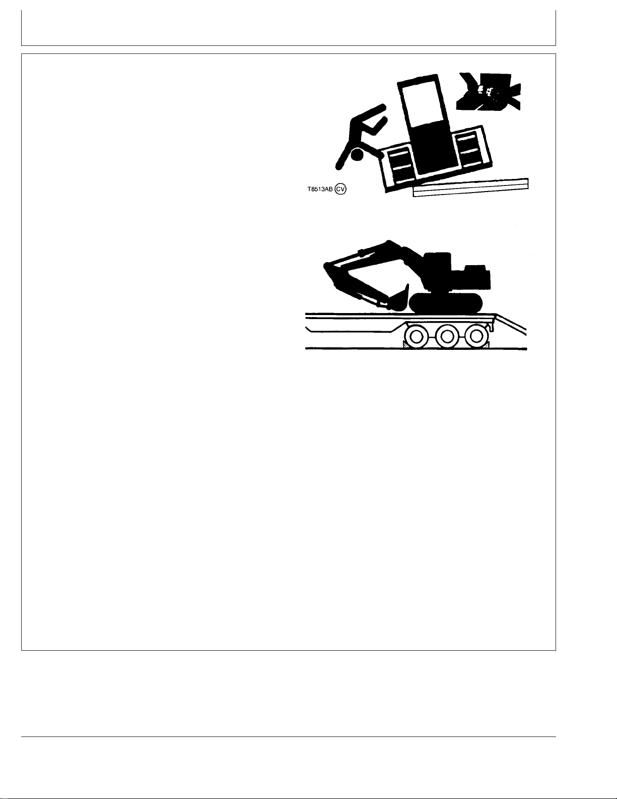
AVOIDINJURYFROM:
LOADINGMACHINEONATRAILER,
FASTENINGMACHINETOTRAILER,
UNLOADINGMACHINEFROMTRAILER
---------------------------------ALWAYSUSECAUTIONWHENLOADING
ANDUNLOADINGMACHINESONATRAILER
---------------------------------ALWAYSKNOWANDFOLLOWTHE
RECOMMENDEDPROCEDURESFORTHE
MACHINE,BECAUSEALLMACHINESARE
NOTLOADED,FASTENED,ANDUNLOADED
THESAMEWAY
---------------------------------ALWAYSKEEPBYSTANDERSCLEAROF
THEAREA
T8513AB –UN–28JUN95T7405BJ –UN–29NOV90
Toavoidinjury:
Keepthetrailerbedclean.
Parkthetraileronafirm,hard,levelsurfacethatwillnot
givewaywhentheweightofthemachineisonthetrailer.
Putchockblocksagainsttruckwheels.
Usearamporloadingdock.Rampsmustbestrong
enoughtoadequatelyhandletheloadandhavealow
angleandcorrectheight.
Ifmachineisequippedwithaseatbelt,fastenitbefore
startingtheengine.
Drivemachineonorofftherampslowly.
fastenchainsorcablestomachinetracksortrackchain
links.Donotplacechainsorcableoveroragainst
hydrauliclinesorhoses.
1-3
TX,05,FF1808 –19–28JUN90–1/1
Page 21

TM 5-3805-280-10
Safety
AVOIDINJURYFROMBACKOVER
ACCIDENTS
---------------------------------BEFOREMOVINGMACHINE,BESUREALL
PERSONSARECLEAROFAREA
---------------------------------ALWAYSBEALERTFORBYSTANDERS
MOVINGINTOTHEWORKAREA.USEHORN
OROTHERSIGNALTOWARNBYSTANDERS
BEFOREMOVINGMACHINE
---------------------------------WHENUSINGASIGNALPERSON,KEEP
PERSONINVIEWATALLTIMES,BESURE
SIGNALPERSONISCLEARBEFORE
BACKINGUP
Toavoidbackoveraccidents:
T7241AY –UN–21FEB90
Alwayslookaroundbeforeyoubackup.Besurethat
everyoneisintheclear.
Keeptravelalarminworkingcondition.
Useasignalpersonwhenbackingupifviewis
obstructed.Alwayskeepsignalpersoninview.
Learnthemeaningofallflags,signs,andmarkingsused
onthejobandwhohastheresponsibilityforsignaling.
Keepwindows,mirrors,andlightscleanandingood
condition.
Dust,heavyrain,fog,etc.,canreducevisibility.As
visibilitydecreases,reducespeedanduseproperlighting.
Readandunderstandtheoperatinginstructionsinthis
operator’smanual.
1-4
TX,05,DY337–19–15MAY96–1/1
Page 22

TM 5-3805-280-10
AVOIDINJURYFROMROLLAWAY
ACCIDENTS
-------------------------------TOPREVENTROLLAWAY,ALWAYSMAKE
SUREMACHINEISPROPERLYSECURED
BEFORELEAVINGOPERATOR’SSEAT
-------------------------------DEATHORSERIOUSINJURYMAYRESULT
IFYOUATTEMPTTOMOUNTORSTOPA
MOVINGMACHINE
Toavoidrollaways:
Selectlevelgroundwhenpossibletoparkmachine.
Pullpilotcontrolshut-offlevertolockedposition.
Lowerallequipmenttoground.
Safety
T7241AZ –UN–21FEB90
Stoptheengine.
Blockalltracksifyoumustparkonagrade.Position
machinetopreventrolling.
Parkareasonabledistancefromothermachines.
Readandunderstandtheoperatinginstructionsinthis
operator’smanual.
INSPECTMACHINE
TX,05,FF2433–19–22MAY91–1/1
Inspectyourmachinecarefullyeachdaybywalking
arounditbeforeyoustartit.(SeePre-StartInspection
Chapter.)
T82,BHSA,CL–19–14MAR90–1/1
T6607AQ –UN–18OCT88
1-5
Page 23

TM 5-3805-280-10
Safety
USEHANDHOLDSANDSTEPS
Fallingisoneofthemajorcausesofpersonalinjury.
Whenyougetonandoffthemachine,alwaysmaintaina
threepointcontactwiththestepsandhandrailsandface
themachine.Donotuseanycontrolsashandholds.
Neverjumponoroffthemachine.Nevermountor
dismountamovingmachine.
Becarefulofslipperyconditionsonplatforms,steps,and
handrailswhenleavingthemachine.
USESEATBELT
Alwaysusetheseatbeltwhenoperatingyourmachine.
T6981AN –UN–15JUN89
TX,05,DH832–19–16MAR92–1/1
TS175 –UN–23AUG88
TX,05,DH3732 –19–18AUG95–1/1
1-6
Page 24

TM 5-3805-280-10
Safety
MAINTAINSEATBELT
Keeptheseatbeltingoodcondition.
Thecompleteseatbeltassemblyshouldbereplaced
afterthreeyearsofusage,regardlessofappearance.
Betweenreplacementintervals:
Carefullyexaminebuckle,webbing,andattaching
hardware.
Besurethattheretractor,ifequipped,lockstoprevent
beltextensionafterlatchingbuckle.
Besurethatattachinghardwareisinplace.Tighten,if
necessary.
Replacetheseatbeltifitdoesnotoperateproperly,orifit
isdamaged,worn,ordeteriorated.
MOVEANDOPERATEMACHINESAFELY
Bystanderscanberunover.Knowthelocationof
bystandersbeforemoving,swinging,oroperatingthe
machine.
Alwayskeepthetravelalarminworkingcondition.It
warnspeoplewhenthemachinestartstomove.
Useasignalpersonwhenmoving,swinging,oroperating
themachineincongestedareas.Coordinatehandsignals
beforestartingthemachine.
TX,05,DH3729 –19–09AUG95–1/1
T7273AL –UN–08JUN90
TX,05,FF1806 –19–05OCT90–1/1
1-7
Page 25

TM 5-3805-280-10
Safety
OPERATEONLYFROMOPERATOR’SSEAT
Avoidpossibleinjuryormachinedamage.Donotstart
enginebyshortingacrossstarterterminals.
NEVERstartenginewhilestandingonground.Start
engineonlyfromoperator’sseat.
SECONDARYEXITS
Machinesequippedwithcabsareequippedwith
secondaryexits.Foradditionalsecondaryexitinformation,
seethetopics”SecondaryExitTool”and’OpeningUpper
Front(SecondaryExit)Window’inchapter10ofthis
manual.
OPERATEMACHINESAFELY
Clearallpersonsfromareaofoperationandmachine
movement.
Useyourseatbelt.
TX,05,FF1615 –19–14JUN90–1/1
T6607AO –UN–18OCT88
TX,05,DH5848 –19–13AUG97–1/1
Makesuretheworksitefootinghassufficientstrengthto
firmlysupportthemachine.Whenworkingclosetoan
excavation,positionmachinewithpropelmotorsatthe
rear.
Becautiousoftippingwhenworkingonfrozenground.
Temperatureincreaseswillcausegroundtobecomesoft,
makinggroundunstable.
Whendiggingdeep,avoidhittingbottomofboomor
bucketcylinderhosesagainsttheground.
Usethebucketonlyfordigging.Donotuseitasajack
hammerorwreckingball.
T7252AL –UN–08JUN90
TX,05,DH3730 –19–09AUG95–1/1
1-8
Page 26

DIGWITHCAUTION
Beforedigging,checkthelocationofcables,gaslines,
andwaterlines.
TM 5-3805-280-10
Safety
OPERATEWITHCAUTION
Avoidcontactofboomorarmandoverheadobstacles
whenyouoperatethemachine.
AVOIDTIPPING
Useyourseatbelt.
Whenoperatingonaslope,keepbucketlowtoground
andclosetomachine.Pointtracksuphill.
05,RR,592–19–12JUN90–1/1
T7252AJ –UN–08JUN90
T7286AJ –UN–08JUN90
TX,05,RR,602 –19–26FEB91–1/1
Avoidtippingthemachinewhenswingingheavyloads.
Reduceswingspeedasnecessary.
Becautiousoftippingwhenworkingonfrozenground.
Temperatureincreaseswillcausegroundtobecomesoft
andmakegroundtravelunstable.
T7273AE –UN–08JUN90
TX,05,DH3731 –19–09AUG95–1/1
1-9
Page 27

TM 5-3805-280-10
AVOIDPOWERLINES
Seriousinjuryordeathcanresultfromcontactwith
electriclines.
Nevermoveanypartofthemachineorloadcloserto
electriclinethan3m(10ft)plustwicethelineinsulator
length.
Safety
DRIVEMACHINESAFELY
Useyourseatbelt.
Beforemovingmachine,findoutwhichwaytomove
propelpedals/leversforthedirectionyouwanttogo.
Pushingdownonthefrontofthepropelpedalsorpushing
theleversmovesthemachinetowardstheidlers.
Keepthebucketontheuphillside,approximately30cm
(12in.)(A)aboveground,whengoingupordownhill.If
machinestartstosliporbecomeunstable,lowerthe
bucketimmediately.
TX,05,RR,594 –19–12JUN90–1/1
T7273AD –UN–08JUN90
T7273AG –UN–08JUN90
TX,05,DH3733 –19–09AUG95–1/1
BEWAREOFEXHAUSTFUMES
Preventasphyxiation.Engineexhaustfumescancause
sicknessordeath.
Ifyoumustoperateinabuilding,bepositivethereis
adequateventilation.Eitheruseanexhaustpipeextension
toremovetheexhaustfumesoropendoorsandwindows
tobringenoughoutsideairintothearea.
02T,05,J9 –19–07JAN91–1/1
T6458AO –UN–18OCT88
1-10
Page 28

PARKMACHINESAFELY
Beforeworkingonthemachine:
•Parkmachineonalevelsurface.
•Lowerbuckettotheground.
•Turnauto-idleswitchoff.
•Runenginewithenginerpmdialat1/3positionfor2
minutes.
•Moveenginerpmdialtoslowidleposition.
•TurnkeyswitchtoOFF.Removekeyfromswitch.
•Pullpilotcontrolshut-offlevertolockedposition.
•Allowenginetocool.
TM 5-3805-280-10
Safety
TX,05,DH5002 –19–28MAY96–1/1
KEEPRIDERSOFFMACHINE
Onlyallowtheoperatoronthemachine.Keepridersoff.
Ridersonmachinearesubjecttoinjurysuchasbeing
struckbyforeignobjectsandbeingthrownoffthe
machine.Ridersalsoobstructtheoperator’sviewresulting
inthemachinebeingoperatedinanunsafemanner.
TX,05,RR,560–19–05OCT90–1/1
T7273AH –UN–08JUN90
1-11
Page 29

TM 5-3805-280-10
Safety
OPERATEATTACHMENTSAFELY
Anattachmentmaychangethecapabilitiesofyour
machineinanyoralloftheseways:
•Saferangeofmotion
•Machinestability
•Hydraulicperformance
•Engineperformance
Readtheattachmentmanualtolearnhowtheattachment
works.
Inanareafreeofbystandersandobstructions,carefully
operatetheattachmenttolearntheavailablerangeof
motion.Anticipatehowobjectsmanipulatedbythe
attachment,ortheattachmentitself,maycontactthe
machine,especiallytheoperator’sstation.Consider
addingguardstothemachinetoprotecttheoperator,and
ifnecessary,topreventdamagetomachine.
Seeyourdealertomatchattachmentdemandsto
machineperformance.
HANDLEFLUIDSSAFELY—AVOIDFIRES
Handlefuelwithcare;itishighlyflammable.Donotrefuel
themachinewhilesmokingorwhennearopenflameor
sparks.Alwaysstopenginebeforerefuelingmachine.Fill
fueltankoutdoors.
TX,05,FF2883 –19–29OCT92–1/1
Continuedonnextpage
1-12
TX,05,FF1622 –19–14JUN90–1/2
TS202 –UN–23AUG88
Page 30

TM 5-3805-280-10
Safety
Storeflammablefluidsawayfromfirehazards.Donot
incinerateorpuncturepressurizedcontainers.
Makesuremachineiscleanoftrash,grease,anddebris.
Donotstoreoilyrags;theycanigniteandburn
spontaneously.
PREPAREFOREMERGENCIES
Bepreparedifafirestarts.
Keepafirstaidkitandfireextinguisherhandy.
Keepemergencynumbersfordoctors,ambulanceservice,
hospital,andfiredepartmentnearyourtelephone.
HANDLESTARTINGFLUIDSAFELY
Startingfluidishighlyflammable.
Keepallsparksandflameawaywhenusingit.Keep
startingfluidawayfrombatteriesandcables.
TX,05,FF1622 –19–14JUN90–2/2
TS227 –UN–23AUG88
TS291 –UN–23AUG88
DX,FIRE2–19–03MAR93–1/1
Topreventaccidentaldischargewhenstoringthe
pressurizedcan,keepthecaponthecontainer,andstore
inacool,protectedlocation.
Donotincinerateorpunctureastartingfluidcontainer.
TS1356 –UN–18MAR92
DX,FIRE3 –19–16APR92–1/1
1-13
Page 31

TM 5-3805-280-10
Safety
CLEANTRASHFROMMACHINE
Keepenginecompartment,radiator,batteries,hydraulic
lines,fueltank,andoperator’sstationclean.
Temperatureinenginecompartmentmaygoup
immediatelyafterengineisstopped.BEONGUARDFOR
FIRESDURINGTHISPERIOD.
Openaccessdoor(s)tocooltheenginefaster,andclean
enginecompartment.
T6669AG –UN–18OCT88
02T,05,J33–19–14MAR90–1/1
PROTECTAGAINSTFLYINGDEBRIS
Guardagainstinjuryfromflyingpiecesofmetalordebris;
weargogglesorsafetyglasses.
WEARPROTECTIVECLOTHING
Wearclosefittingclothingandsafetyequipment
appropriatetothejob.
Operatingequipmentsafelyrequiresthefullattentionof
theoperator.Donotwearradioormusicheadphones
whileoperatingmachine.
TX,05,FF1613 –19–14JUN90–1/1
T6642DK –UN–18OCT88
1-14
DX,WEAR2 –19–03MAR93–1/1
TS206 –UN–23AUG88
Page 32

TM 5-3805-280-10
PROTECTAGAINSTNOISE
Prolongedexposuretoloudnoisecancauseimpairment
orlossofhearing.
Wearasuitablehearingprotectivedevicesuchas
earmuffsorearplugstoprotectagainstobjectionableor
uncomfortableloudnoises.
Safety
HANDLECHEMICALPRODUCTSSAFELY
Directexposuretohazardouschemicalscancause
seriousinjury.Potentiallyhazardouschemicalsusedwith
yourmachineincludesuchitemsaslubricants,coolants,
paints,andadhesives.
AMaterialSafetyDataSheet(MSDS)providesspecific
detailsonchemicalproducts:physicalandhealthhazards,
safetyprocedures,andemergencyresponsetechniques.
ChecktheMSDSbeforeyoustartanyjobusinga
hazardouschemical.Thatwayyouwillknowexactlywhat
therisksareandhowtodothejobsafely.Thenfollow
proceduresandrecommendedequipment.
SeeyourauthorizeddealerforMSDS’sonchemical
productsusedwithyourmachine.
DX,NOISE–19–03MAR93–1/1
TS207 –UN–23AUG88
TS1132 –UN–26NOV90
1-15
TX,05,DH2500 –19–02OCT92–1/1
Page 33

TM 5-3805-280-10
Safety
WARNOTHERSOFSERVICEWORK
Unexpectedmachinemovementcancauseseriousinjury.
Beforeperforminganyworkonthemachine,attacha’Do
NotOperate’tagontherightcontrollever.
STAYCLEAROFMOVINGPARTS
Entanglementsinmovingpartscancauseseriousinjury.
Topreventaccidents,usecarewhenworkingaround
rotatingparts.
TX,05,RR,566 –19–23JUL91–1/1
T7273AP –UN–08JUN90
T7273AS –UN–08JUN90
TX,05,RR,572 –19–12JUN90–1/1
1-16
Page 34

TM 5-3805-280-10
Safety
SUPPORTMACHINEPROPERLY
Alwayslowertheattachmentorimplementtotheground
beforeyouworkonthemachine.Ifyoumustworkona
liftedmachineorattachment,securelysupportthe
machineorattachment.
Donotsupportthemachineoncinderblocks,hollowtiles,
orpropsthatmaycrumbleundercontinuousload.Donot
workunderamachinethatissupportedsolelybyajack.
Followrecommendedproceduresinthismanual.
TS229 –UN–23AUG88
DX,LOWER–19–04JUN90–1/1
SERVICECOOLINGSYSTEMSAFELY
Explosivereleaseoffluidsfrompressurizedcooling
systemcancauseseriousburns.
Shutoffengine.Onlyremovefillercapwhencoolenough
totouchwithbarehands.Slowlyloosencaptofirststop
torelievepressurebeforeremovingcompletely.
DX,RCAP –19–04JUN90–1/1
TS281 –UN–23AUG88
1-17
Page 35

TM 5-3805-280-10
PRACTICESAFEMAINTENANCE
Understandserviceprocedurebeforedoingwork.Keep
areacleananddry.
Neverlubricateorservicemachinewhileitismoving.
Keephands,feetandclothingfrompower-drivenparts.
Beforeservicingmachine.
•Parkmachineonalevelsurface.
•Lowerbuckettotheground.
•Turnauto-idleswitchoff.
•Runenginewithenginerpmdialat1/3speedfor2
minutes.
•Moveenginerpmdialtoslowidleposition.
•TurnkeyswitchtoOFF.Removekeyfromswitch.
•Attacha’DoNotOperate’tagontherightside
controllerlever.
•Pullpilotcontrolshut-offlevertolockedposition.
•Allowenginetocool.
Safety
Ifmaintenanceproceduremustbeperformedwithengine
running,donotleavemachineunattended.
Securelysupportanymachineelementsthatmustbe
raisedforservicework.Neverworkunderamachine
raisedbytheboom.Ifthemachinemustberaised,keep
a90-110°anglebetweenboomandarm.
Keepallpartsingoodconditionandproperlyinstalled.Fix
damageimmediately.Replacewornorbrokenparts.
Removeanybuildupofgrease,oil,ordebris.
Disconnectbatterygroundcable(-)beforemaking
adjustmentsonelectricalsystemsorweldingonmachine.
TS218 –UN–23AUG88
1-18
TX,05,DH5001 –19–28MAY96–1/1
Page 36

TM 5-3805-280-10
Safety
REMOVEPAINTBEFOREWELDINGOR
HEATING
Avoidpotentiallytoxicfumesanddust.
Hazardousfumescanbegeneratedwhenpaintisheated
bywelding,soldering,orusingatorch.
Doallworkoutsideorinawellventilatedarea.Disposeof
paintandsolventproperly.
Removepaintbeforeweldingorheating:
•Ifyousandorgrindpaint,avoidbreathingthedust.
Wearanapprovedrespirator.
•Ifyouusesolventorpaintstripper,removestripperwith
soapandwaterbeforewelding.Removesolventor
paintstrippercontainersandotherflammablematerial
fromarea.Allowfumestodisperseatleast15minutes
beforeweldingorheating.
AVOIDHEATINGNEARPRESSURIZEDFLUID
LINES
Flammablespraycanbegeneratedbyheatingnear
pressurizedfluidlines,resultinginsevereburnsto
yourselfandbystanders.Donotheatbywelding,
soldering,orusingatorchnearpressurizedfluidlinesor
otherflammablematerials.Pressurizedlinescanbe
accidentallycutwhenheatgoesbeyondtheimmediate
flamearea.
TS220 –UN–23AUG88
DX,PAINT–19–03MAR93–1/1
1-19
TS953 –UN–15MAY90
DX,TORCH –19–03MAR93–1/1
Page 37

TM 5-3805-280-10
Safety
AVOIDHIGH-PRESSUREFLUIDS
Escapingfluidunderpressurecanpenetratetheskin
causingseriousinjury.
Avoidthehazardbyrelievingpressurebefore
disconnectinghydraulicorotherlines.Tightenall
connectionsbeforeapplyingpressure.
Searchforleakswithapieceofcardboard.Protecthands
andbodyfromhighpressurefluids.
Ifanaccidentoccurs,seeadoctorimmediately.Anyfluid
injectedintotheskinmustbesurgicallyremovedwithina
fewhoursorgangrenemayresult.Doctorsunfamiliarwith
thistypeofinjuryshouldreferenceaknowledgeable
medicalsource.SuchinformationisavailablefromDeere
&CompanyMedicalDepartmentinMoline,Illinois,U.S.A.
X9811 –UN–23AUG88
PREVENTBATTERYEXPLOSIONS
Keepsparks,lightedmatches,andopenflameawayfrom
thetopofbattery.Batterygascanexplode.
Nevercheckbatterychargebyplacingametalobject
acrosstheposts.Useavolt-meterorhydrometer.
Donotchargeafrozenbattery;itmayexplode.Warm
batteryto16°C(60°F).
DX,FLUID –19–03MAR93–1/1
TS204 –UN–23AUG88
DX,SPARKS –19–03MAR93–1/1
1-20
Page 38

TM 5-3805-280-10
Safety
CLEANTHEMACHINEREGULARLY
Removeanygrease,oil,fuel,ordebrisbuild-uptoavoid
possibleinjuryormachinedamage.
Highpressurewashing[greaterthan1379kpa(13.8bar)
(200psi)]candamagefreshlypaintedfinishes.Paint
shouldbeallowedtoairdryfor30daysminimumafter
receiptofmachinebeforecleaningwithhighpressure.
Uselowpressurewashoperationsuntil30dayshave
elapsed.
Donotsprayoilcoolerfinsatanangle.Finsmaybend.
T6642EJ –UN–18OCT88
TX,05,FF2787–19–27JUL94–1/1
STOREATTACHMENTSSAFELY
Storedattachmentssuchasbuckets,hydraulichammers,
andbladescanfallandcauseseriousinjuryordeath.
Securelystoreattachmentsandimplementstoprevent
falling.Keepplayingchildrenandbystandersawayfrom
storagearea.
TX,05,RR,576 –19–26APR90–1/1
TS219 –UN–23AUG88
1-21
Page 39

TM 5-3805-280-10
Safety
BATTERYTERMINALS,LIFTING
EQUIPMENT,DRYCLEANINGSOLVENTAND
COMPRESSEDAIR
WARNING:Avoidpossibleinjury.Disconnectthe
negativeterminalfirstandreconnectthenegative
terminallastwhendisconnecting/reconnectingbattery
terminals.
WARNING:Whenliftingequipment,ensurethatthe
liftingdeviceiscapableofsupportingthedesired
weightsandtheinspectiondatestampedonthelifting
devicehasnotexpired.
WARNING:DrycleaningsolventPD-680TypeIIIis
toxicandflammable.Wearprotectivegogglesand
glovesanduseonlyinawellventilatedarea.Avoid
contactwithskin,eyes,andclothesanddon’tbreathe
vapors.Donotusenearopenflamesorexcessive
heat.Theflashpointis200°F(93°C).Ifyoubecome
dizzywhileusingsolvent,getfreshairimmediately
andgetmedicalaid.Ifcontactwitheyesismade,
washyoureyeswithwaterandgetmedicalaid
immediately.
WARNING:Compressedairusedforcleaning
purposesshallnotexceed30psi.Useonlywith
effectivechipguardingandpersonnelprotective
equipment(goggles/shield/gloves,etc.).
CED,OUOE042,44–19–19OCT99–1/1
1-22
Page 40

TM 5-3805-280-10
Safety
DISPOSEOFWASTEPROPERLY
Improperlydisposingofwastecanthreatenthe
environmentandecology.Potentiallyharmfulwasteused
withyourmachineincludesuchitemsasoil,fuel,coolant,
brakefluid,filters,andbatteries.
Useleakproofcontainerswhendrainingfluids.Donotuse
foodorbeveragecontainersthatmaymisleadsomeone
intodrinkingfromthem.
Donotpourwasteontotheground,downadrain,orinto
anywatersource.
Airconditioningrefrigerantsescapingintotheaircan
damagetheEarth’satmosphere.Governmentregulations
mayrequireacertifiedairconditioningservicecenterto
recoverandrecycleusedairconditioningrefrigerants.
Inquireontheproperwaytorecycleordisposeofwaste
fromyourlocalenvironmentalorrecyclingcenter,orfrom
yourauthorizeddealer.
TS1133 –UN–26NOV90
TX,05,DH2502 –19–26AUG92–1/1
1-23
Page 41

TM 5-3805-280-10
DRILLING
Before starting work, the operator will make sure
there are no buried electrical, gas, water or other
pipes or lines.
Always be aware of previously drilled holes, and
where they are located : any open hole can cause severe injury to the operator or someone else. The loss
of tools, drill rods, drill bits or any other item can occur.
Safety
be ready to activate the cabin emergency stop if need
be.
communication must be established in a reli-
able manner.
Make sure any hand signal will be perfectly
understood.
the operator must make sure the following
safety decal is affixed on the drill guide to warn the
service man of risks incurred.
! !
#
"#!
#
the service man must be informed about the
use of the emergency stop mounted on the guide.
$" ! #
#
"#
"
When rising the guide, take care of any overhead
lines.
Always maintain a minimum distance of 25 Ft.
(7.6 m) distance between the machine and any
overhead lines during any operation.
The operator will make sure that everybody
stands clear from the machine in operation and stays
at a distance of 7 meters (25 ft.).
Nevertheless, some operations may need people
to enter the restricted area (checking of coupling temperature during feed thrust adjustment for instance).
On such an occasion :
the operator must supervise, from the cabin,
the safety of the service man doing the work. He must
Always have the cabin door closed and the dust
collector running when drilling to prevent respiratory
damage.
Keep all work areas clean and orderly.
ROCK DRILL MAINTENANCE
Keep hands, arms, legs and clothing away from
moving or rotating parts.
Only use genuine replacement parts.
Stopping the drill for mainte-
nance or bit change etc...
Prior to leaving the operators compartment, the
excavators hydraulic safety arm must be raised to
lock in the machines safety switch. This renders all
controls inoperable thus preventing any unwanted
movement.
Hydraulic cylinder
The hydraulic cylinder is equipped with 2 load–
sustaining valves.
The load–sustaining valves allow the disconnecting of the hydraulic hoses from the cylinder if they
need to be changed. But :
1-24
Page 42

TM 5-3805-280-10
Safety
Respiratory damage prevention
Never disconnect a valve from the cylinder
without supporting the controlled element (drill
guide ...).
Burn prevention
At operating temperature, the hydraulic tank, circuit and components are hot and can be under pressure. Any contact can cause severe burns.
Always release the pressure and wait for cooling before intervening on the hydraulic circuit.
W RNING
Dust coming out from the dust collector fan indicates that one or several filter elements are damaged.
Change the damaged elements immediately.
Always dismount all the filters elements to check
the functioning of the automatic filter cleaning sequence.
Compressed air
Compressed air can be dangerous.
Never point an air hose at yourself or co–workers.
Be sure all hoses and fittings are tightly secured.
A loose hose not only leaks but can come completely off and while whipping under pressure, can
injure the operator and others in the area.
Never disconnect a pressurized air hose.
W RNING
Fire prevention
Fuel or hydraulic oil leaked or spilled onto hot sur-
faces or electrical components can cause a fire.
Repair immediately any leaks.
Regularly clean the machine to remove all flam-
mable materials such as fuel, oil and other debris.
Always use approved safety solvent when clean-
ing parts or the machine.
Have all loose electrical wires connected and tight
before operating the machine.
Prior to any welding operation, make sure that the
surfaces and their environment are free of flammable
debris.
EMERGENCY STOPS
The CPA remote control assembly incorporates
an emergency stops selector with allows to connect
the CPA emergency stops to the machine circuit.
B
– When the CPA is installed, place the selector on position A to have the CPA emergency stops
active.
– Place the selector on position B to refind the
normal excavator safety circuit when the CPA is not
used.
1-25
Page 43

The CPA safety circuit incorporates 2 emergency
stops.
One mushroom type push–button is located in the
cabin on the remote control panel.
Pressing on this button shuts down the engine.
Unlock the knob by pulling it up to be in position to
restart the engine.
TM 5-3805-280-10
Safety
wire
The second emergency stop is located on the
guide rail, and stops the engine when pulling on the
wire attached along the guide.
To unlock the safety device and be in position to
restart the engine, press on the button.
WARNING: Take all necessary steps to safely
start the engine after emergency stop.
1-26
Page 44

SAFETYSIGNS
TM 5-3805-280-10
SafetySigns
Caution Decal (Model 230LCR)
T125071 –UN–28OCT99
T125070 –UN–28OCT99
Caution Decal (Model 230LCRD)
Continuedonnextpage
1-27
Caution Decal Location
T125069 –UN–28OCT99
TX,06,DH5564 –19–22MAR99–1/11
Page 45

TM 5-3805-280-10
Safety Signs
A—DangerDecalLocation
Continuedonnextpage
T7748CZ –19–14OCT92
T101484 –UN–27JUN96
TX,06,DH5564 –19–22MAR99–2/11
1-28
Page 46

TM 5-3805-280-10
Safety Signs
T7748DA –19–14OCT92
A—WarningDecalLocation
Continuedonnextpage
T101485 –UN–27JUN96
TX,06,DH5564 –19–22MAR99–3/11
1-29
Page 47

TM 5-3805-280-10
Safety Signs
A-Caution Decal
Continuedonnextpage
T102888 –19–23AUG96
T101483 –UN–27JUN96
A—CautionDecalLocation
TX,06,DH5564 –19–22MAR99–4/11
1-30
Page 48

TM 5-3805-280-10
Safety Signs
T108112B –UN–27MAR97
T7972AP –19–22MAR93
Continuedonnextpage
TX,06,DH5564 –19–22MAR99–5/11
1-31
Page 49

TM 5-3805-280-10
Safety Signs
T7748DC –19–14OCT92
T7748CX –19–14OCT92
Continuedonnextpage
T8167AL –UN–06FEB94
A—WarningDecalLocation
TX,06,DH5564 –19–22MAR99–6/11
T7748DH –UN–15OCT92
TX,06,DH5564 –19–22MAR99–7/11
1-32
Page 50

TM 5-3805-280-10
Safety Signs
T7748DK –UN–22OCT92
A—CautionDecalLocation
T101279 –19–14MAY96
T7900AB –19–03DEC92
Continuedonnextpage
TX,06,DH5564 –19–22MAR99–8/11
T7869BZ –UN–05NOV92
TX,06,DH5564 –19–22MAR99–9/11
1-33
Page 51

TM 5-3805-280-10
Safety Signs
Decal is located on top of each battery.
Continuedonnextpage
T6888AC –19–06JAN89
TX,06,DH5564 –19–22MAR99–10/11
1-34
Page 52

TM 5-3805-280-10
Safety Signs
1-35
T120457 –19–25MAR99
TX,06,DH5564 –19–22MAR99–11/11
Page 53

TM 5-3805-280-10
Safety Signs
Look for these signs on machine, which points out potential hazards to the safety of you and others. Read and
understand thoroughly. Heed warnings and follow instructions. If you do not understand, inform your
supervisor.
Indicates the presence of a hazard which WILL cause serious
injury, death or property damage, if ignored.
Indicates the presence of a hazard which CAN cause serious
injury, death or property damage, if ignored.
Indicates the presence of a hazard which WILL or can cause
injury or property damage, if ignored.
Indicates important set-up, operating or maintenance
information.
1-36
Page 54

TM 5-3805-280-10
1-37
Page 55

TM 5-3805-280-10
BLANK
1-38
Page 56

TM 5-3805-280-10
CHAPTER 2
OPERATOR’S STATION
Page 57

TM 5-3805-280-10
BLANK
Page 58

Operator’sStation
PEDALS,LEVERSANDPANELS
TM 5-3805-280-10
T121034 –UN–29OCT99
A—LeftControlLever/HornSwitch(OnTopof
Lever)
B—LeftTravelPedal
C—LeftTravelLever
D—RightTravelLever
E—RightTravelPedal
F—RightControlLever/PowerBoostSwitch(On
TopofLever)
G—FrontRightPanel
H—RightConsolePanel
I—AirConditionerPanel—IfEquipped
J—CabDoorReleaseLever
K—Radio
L—LeftConsolePanel
M—PilotControlShut-OffLever
N—HydraulicThumbPedal(Model230LCR)
O—RockDrillControlPanel(Model230LCRD)
CED,OUOE042,5058 –19–14APR99–1/1
2-1
Page 59

TM 5-3805-280-10
Operator’s Station
RIGHTFRONTPANELANDRIGHTCONSOLE
PANEL
A—MonitorPanel
B—SwitchPanel
C—AshTray
D—CigarLighter
E—AirConditionerPanel-IfEquipped
F—EngineRPMDial
G—E(Economy)ModeSwitch
H—H/P(HighPower)ModeSwitch
I—KeySwitch
J—RearLightSwitch
K—OverloadAlarm/Indicator
L—ArcticHeaterSwitch
M—ArcticHeaterIndicator
2-2
T121035 –UN–14APR99
TX,10,DH5708–19–21APR97–1/1
Page 60

MONITORPANEL
TM 5-3805-280-10
Operator’s Station
A—EngineCoolantTemperatureGauge
B—Warm-upIndicator
C—FuelGauge
D—H/P(HighPower)ModeIndicator
E—E(Economy)ModeIndicator
F—Auto-IdleIndicator
G—HydraulicOilFilterRestrictionIndicator
(Model230LCRD)
H—HydraulicOilLevelIndicator
I—FuelLevelIndicator
J—AirFilterRestrictionIndicator
K—ChargeAirTemperatureIndicator
L—EngineCoolantTemperatureIndicator
M—EngineOilPressureIndicator
N—AlternatorVoltageIndicator
O—EngineOilLevelIndicator
P—EngineCoolantLevelIndicator
CED,OUOE020,15–19–03MAR99–1/1
T120386 –UN–25MAR99
2-3
Page 61

TM 5-3805-280-10
Operator’s Station
ENGINECOOLANTTEMPERATUREGAUGE
IMPORTANT:Ifneedlepointsto’RED’zone,idle
enginetobringbackneedleto’GREEN’
zonebeforestoppingengine.Ifneedle
continuestorise,shutengineOFF.
WARM-UPINDICATOR
Yellowindicatorwillturnoffwhentheenginecoolant
temperaturereachesapproximately30°C(86°F).
T101569 –UN–11JUL96
TX,10,DH5451–19–25JUN96–1/1
FUELGAUGE
Fuelmachinebeforeneedlereaches“E”.
H/P(HIGHPOWER)MODEINDICATOR
GreenindicatorwilllightwhentheH/Pmodeswitchis
turnedon.
T101574 –UN–11JUL96
TX,10,DH5453 –19–04MAR97–1/1
T101570 –UN–11JUL96
TX,10,DH5454–19–04JUN96–1/1
2-4
T101571 –UN–11JUL96
TX,10,DH5455 –19–11JUL96–1/1
Page 62

Operator’s Station
E(ECONOMY)MODEINDICATOR
GreenindicatorwilllightwhentheEmodeswitchis
turnedon.
AUTO-IDLEINDICATOR
Greenindicatorwilllightwhentheauto-idleswitchis
turnedon.
TM 5-3805-280-10
T101572 –UN–11JUL96
TX,10,DH5456–19–17JUN96–1/1
HYDRAULICOILLEVELINDICATOR
Parkmachineonlevelground.
Positionmachinewitharmcylinderfullyretractedand
bucketcylinderfullyextended.
Pressingthelevelcheckswitchbeforestartingthe
machinewillturntheindicatoronifoillevelisadequate
foroperation.
NOTE: This check does NOT take the place of daily
inspection.
T101573 –UN–11JUL96
TX,10,DH5457–19–17JUN96–1/1
T101577 –UN–27JUN96
TX,10,DH5458–19–04JUN96–1/1
2-5
Page 63

TM 5-3805-280-10
Operator’s Station
HYDRAULICOILFILTERRESTRICTION
INDICATOR(MODEL230LCRD)
IMPORTANT:Preventpossiblehydraulicpump
damage.Changehydraulicoilfilteras
soonaspossiblewhenaproblem
occurs.
Indicatorlightwilllightandservicerequiredindicatorlight
willlightwhenfilterelementsarerestricted.Changefilter
elements.
NOTE: Cold oil may cause hydraulic oil filter restriction
indicator light to light temporarily.
T8381AG –UN–03JAN95
CED,OUOE020,16–19–03MAR99–1/1
FUELLEVELINDICATOR
Whenredfuelindicatorlights,approximately30liters(8
gal.)offuelremain.
AIRFILTERRESTRICTIONINDICATOR
Redindicatorwilllightwhentheairfilterelementsare
clogged.Cleanorreplaceelements.
T101578 –UN–27JUN96
TX,10,DH5459–19–25JUN96–1/1
2-6
T101580 –UN–27JUN96
TX,10,DH5460–19–04JUN96–1/1
Page 64

Operator’s Station
ENGINECOOLANTTEMPERATURE
INDICATOR
IMPORTANT:Donotstopenginewhencoolant
temperaturelightcomesonor
temperaturewillrisefurther.Reduce
loadandrunengineatslowidle.If
temperaturelightcontinuestostayON,
shutengineOFF.
TM 5-3805-280-10
Redindicatorwilllightandbuzzerwillsoundwhenthe
enginecoolantoverheats.Reduceloadimmediatelyand
runengineatslowidle.Inspectfordebrisaroundradiator.
Checkforlowcoolantlevelintheradiatorrecoverytank.
CHARGEAIRTEMPERATUREINDICATOR
IMPORTANT:Preventpossibleenginedamage.If
chargeairindicatorlightcomeson
whileoperating,stopengine.
Redindicatorwilllightwhenairintaketemperatureis
excessivelyhigh.Stopengine.Checkfordebrisoncharge
aircoolerinletscreens.Checkfanforproperoperation.A
cloggedchargeairsystemwillreduceengine
performance.
T101581 –UN–11JUL96
TX,10,DH5461–19–04JUN96–1/1
T107672 –UN–27FEB97
2-7
TX,10,DH5712–19–21APR97–1/1
Page 65

TM 5-3805-280-10
Operator’s Station
ENGINEOILPRESSUREINDICATOR
IMPORTANT:Ifengineoilpressurelightcomeson
whileoperating,stopengine
immediately.
Redindicatorwilllightandbuzzerwillsoundwhenengine
oilpressureislow.Stopengineimmediately.
NOTE: Cold oil, low oil level, or extreme off level
operation may cause indicator to light.
T101579 –UN–27JUN96
TX,10,DH5462–19–04JUN96–1/1
ALTERNATORVOLTAGEINDICATOR
Indicatorwilllightwithnoalternatoroutput.Check
electricalsystem.
ENGINEOILLEVELINDICATOR
Pressingthelevelcheckswitchbeforestartingthe
machinewillturntheindicatoronifoillevelisadequate
foroperation.
NOTE: This check does NOT take the place of daily
inspection.
T101582 –UN–27JUN96
TX,10,DH5463–19–09APR92–1/1
2-8
T101575 –UN–27JUN96
TX,10,DH5464–19–18JUN96–1/1
Page 66

Operator’s Station
COOLANTLEVELINDICATOR
Pressingthelevelcheckswitchbeforestartingthe
machinewillturntheindicatoronifcoolantlevelis
adequateforoperation.
NOTE: This check does NOT take the place of daily
inspection.
TM 5-3805-280-10
T101576 –UN–27JUN96
TX,10,DH5465–19–04JUN96–1/1
2-9
Page 67

SWITCHPANEL
TM 5-3805-280-10
Operator’s Station
A—LevelCheckSwitch
B—AttachmentModeIndicator
C—PrecisionModeIndicator
D—GradingModeIndicator
E—DigModeIndicator
F—WorkModeSwitch
G—BuzzerStopSwitch
H—PropelSpeedSwitch
I—Auto-idleSwitch
J—WiperSwitch
K—WasherSwitch
L—OperatingLightsSwitch
T107673 –UN–27FEB97
TX,10,DH5466–19–27FEB97–1/1
2-10
Page 68

TM 5-3805-280-10
Operator’s Station
BUZZERANDBUZZERSTOPSWITCH
THEBUZZERSOUNDSWHEN:
•Engineoilpressureislow(indicatorlight(C)willalso
light).Ifengineoilpressureislow,stoptheengine
immediately.
NOTE: The buzzer cannot be turned off when engine oil
pressure is low.
•Enginecoolantoverheats(indicatorlight(B)willalso
light).Ifcoolanttemperatureishigh,pushbuzzerstop
switch(A),reduceloadimmediately,andrunengineat
decreasedenginespeed.Ifhightemperaturecontinues,
stoptheengine.Checkfluidlevels.
Whenthebuzzerstopswitchispushedandreleasedthe
buzzerstopssoundingandthebuzzerfunctionis
automaticallyresetfortheenginecoolantoverheat
function.
TORESETTHEBUZZER:
TurnthekeyswitchtoOFF.Thebuzzerwillnotsound
morethanonceforthesameproblemunlesstheswitchis
reset.
WIPERSWITCH
Wiperswitch(A)hasthreepositions.
•INTposition.......Wiperstartsoperatingintermittently.
•ONposition........Wiperoperatescontinuously
•OFFposition.......Wiperautomaticallystopsoperating.
NOTE: The wiper and washer do not operate unless the
upper front window is closed and the right-side
lock pin is installed.
T107674 –UN–27FEB97
TX,10,DH5832 –19–24JUL97–1/1
T101626 –UN–20JUN96
2-11
TX,10,DH5468–19–18JUN96–1/1
Page 69

Operator’s Station
WASHERSWITCH
IMPORTANT:Washermotormaybedamagedif
washerswitchishelddownformore
than20seconds,orcontinually
operatedwithnofluidincontainer.
Pushswitch(A)tosquirtwindshieldwasherfluidon
windshield.Donotholddownswitchformorethan20
seconds.
TM 5-3805-280-10
T101627 –UN–20JUN96
TX,10,DH5469–19–04JUN96–1/1
OPERATINGLIGHTSSWITCH
Turnlightswitch(A)tofirstpositiontoturnonlight(C).
Turnlightswitchtosecondpositiontoturnonlights(B
andC).
T101591 –UN–27JUN96
T120793 –UN–25MAR99
2-12
CED,OUOE042,23–19–05MAR99–1/1
Page 70

TM 5-3805-280-10
Operator’s Station
OPERATINGREARLIGHTSSWITCH
Moveswitch(A)toturntherearoutsideworklightsonor
off.
CABLIGHT
Moveswitch(A)toturntheinsidecablightonoroff.
T120402 –UN–25MAR99
CED,OUOE042,19–19–03MAR99–1/1
OVERLOADALARMANDINDICATOR
Theoverloadalarmandindicator(A)willactivatewhen
thediggingcapacityisexceeded,whilethemachineis
diggingfromtheside.
T101592 –UN–27JUN96
TX,10,DH5471–19–18JUN96–1/1
T120413 –UN–25MAR99
CED,OUOE020,18–19–03MAR99–1/1
2-13
Page 71

TM 5-3805-280-10
Operator’s Station
KEYSWITCH
EnginewillstopwhenkeyswitchisturnedfromONto
ACC.AlwaysturnkeytoOFFpositiontopreventbatteries
fromdraining.
T7396DS –UN–27JUN91
A—EngineOff
B—Accessory
C—EngineOn
D—Start
TX,10,DH5472 –19–29MAY96–1/1
ENGINERPMDIAL
Useenginerpmdial(A)toadjustenginespeed.Turndial
clockwisetoincreaseenginespeedorcounterclockwiseto
decreaseenginespeed.
POWERBOOSTSWITCH
Powerboostswitch(A)islocatedontopofrightcontrol
lever.
T101628 –UN–20JUN96
TX,10,DH5473–19–19JUN96–1/1
2-14
T101633 –UN–20JUN96
TX,10,DH5591 –19–22MAR97–1/1
Page 72

Operator’s Station
HORN
Hornswitch(A)islocatedontopofleftcontrollever.
HOURMETER
Therighthandnumberonthehourmeter(A)indicates
tenthsofanhour(sixminutes).
TM 5-3805-280-10
T101634 –UN–20JUN96
TX,10,DH5475–19–04JUN96–1/1
TX,10,DH5476–19–24JUN96–1/1
T101639 –UN–26JUN96
2-15
Page 73

CABHEATERANDAIRCONDITIONER
TM 5-3805-280-10
Operator’s Station
A—ControlPanel
B—FrontVent
C—DefrosterVent
D—FootVent
E—RearVents
T101645 –UN–20JUN96
TX,10,DH5480–19–19JUN96–1/1
2-16
Page 74

Operator’s Station
CONTROLPANELSWITCHES
ModeSwitches
(A)Airflowsoutoffrontventanddefrostervent.
(B)Airflowsoutoffrontandrearvents,anddefroster
vent.
(C)Airflowsoutoffootventonly.
TM 5-3805-280-10
TemperatureControlSwitches
Eightindicatorsaresituatedjustabovethetemperature
controlswitches(I).Theindicatorswillturnredwhenthe
rightarrowswitchispressed,andgreenwhentheleft
arrowswitchispressed.Airtemperatureishighestifall
indicatorsarered,andcoolestifallindicatorsaregreen.
Eitherwarmorcoolairwillflowoutofvent(s)selectedby
themodeswitches.
BlowerSwitches
Pressblowerswitches(G)toselectdesiredblowerspeed.
AirconditionerwillturnonwhenA/Cswitch(D)ispressed
andanyoftheblowerindicatorsison.WhenblowerOFF
switch(H)ispressed,theblowerandtheairconditioner
willturnoff.Theblowerwillturnonifoneoftheblower
switchesispressedwhethertheairconditionerswitchis
turnedonoroff.
FreshAirVentSwitch
Pressfreshairventswitch(F)torouteoutsideairintothe
cab.Pressairventswitch(E)toclosefreshairventand
circulateairalreadyincab.
T102753 –UN–05AUG96
A—ModeSwitch
B—ModeSwitch
C—ModeSwitch
D—AirConditionerSwitch
E—AirVentSwitch
F—FreshAirVentSwitch
G—BlowerSwitches
H—BlowerOFFSwitch
I—TemperatureControlSwitches
2-17
TX,10,DH5481–19–19JUN96–1/1
Page 75

TM 5-3805-280-10
Operator’s Station
CABHEATEROPERATION
1.Pressdesiredmodeswitch(A,B,orC).
2.Pressrighttemperaturecontrolswitch(I)untilall
indicatorsarered.
3.Pressblowerswitch(Gtoselectdesiredblowerspeed.
4.Pressairconditionerswitch(D)toturnindicatoroffif
notalreadyoff.
5.Presstemperaturecontrolswitchesandblower
switchestoadjustcabtemperature
T102753 –UN–05AUG96
TX,10,DH5633 –19–26MAR97–1/1
AIRCONDITIONEROPERATION
1.Pressdesiredmodeswitch(A,B,orC).
2.Presslefttemperaturecontrolswitch(I)untilall
indicatorsaregreen.
3.Pressblowerswitch(G)toselectdesiredblower
speed.
4.Pressairconditionerswitch(D)toturnindicatorgreen
ifnotalreadygreen.
5.Presstemperaturecontrolswitchesandblower
switchestoadjustcabtemperature
T102753 –UN–05AUG96
TX,10,DH5483–19–20JUN96–1/1
2-18
Page 76

TM 5-3805-280-10
Operator’s Station
DEFROSTEROPERATION
1.Pressfrontventmodeswitch(A)orrearventmode
switch(B).
2.Presstemperaturecontrolswitches(I)toselectdesired
airtemperature.
3.Pressfreshairventswitch(F).
4.Pressblowerswitches(G)toselectdesiredblower
speed.
5.Adjustthelouversonfrontventanddefrosterventas
required.
6.Presstemperaturecontrolswitchesandblower
switchestoadjustcabtemperature.
7.Pressairconditionerswitch(F)onifwindowsbecome
cloudedorifdehumidifyingisrequired.
FRONTCONSOLE
T102753 –UN–05AUG96
TX,10,DH5484–19–20JUN96–1/1
2-19
T101647 –UN–07AUG96
A—Radio/Clock
TX,10,DH5485–19–20JUN96–1/1
Page 77

TM 5-3805-280-10
Operator’s Station
OPERATINGTHEAM/FMRADIO
Presspowerswitch(A)toturnradioon,andrepeatedly
pressoneoftuningswitches(D)untildesiredstationis
reached.Topresetastation,selectthedesiredstation
usingtuningswitches.Pressandholdstationpreset(F)
formorethan2secondsuntilanelectronictoneisheard.
Thefrequencyofthepresetstationwillbeindicatedon
digitaldisplay(G).
T101691 –UN–24JUN96
A—PowerSwitch/VolumeControlKnob
B—ToneAdjustmentRing
C—AM/FMSwitch
D—TuningSwitches
E—DisplayModeChangeSwitch
F—StationPresets
G—DigitalDisplay
H—SetSwitch
I—TimeSetSwitches
SETTINGTHECLOCK
NOTE: In order to set the clock, digital display (B) must
be in the time display mode.
Whilepressingdisplaymodechangeswitch(A)usetime
setswitches(C)andsetswitch(D)tosettheclock.
Presssetswitchtoresettheminutedisplayto“00”.
Presstimesetswitch(H)tosetcorrecthour.
Presstimesetswitch(M)tosetcorrectminute.
TX,10,DH5486–19–06JUN96–1/1
T101692 –UN–24JUN96
A—DisplayModeChangeSwitch
B—DigitalDisplay
C—TimeSetSwitches
D—SetSwitch
TX,10,DH5487–19–06JUN96–1/1
2-20
Page 78

TM 5-3805-280-10
Operator’s Station
CABDOORRELEASELEVER
Thecabdoorcanbelockedintheopenposition.Open
thedoorallthewayuntilitlocksinthelatchonthesideof
thecab.
Toreleasethedoorfromthislockedposition,pushdown
onlever(A).
SECONDARYEXITTOOL
IMPORTANT:FORSECONDARYEXIT.Usetool(A)to
breakwindow.Alwayskeeptoolin
machine.
T101648 –UN–07AUG96
TX,10,DH5488–19–04JUN96–1/1
OPENINGUPPERFRONT(SECONDARY
EXIT)WINDOW
NOTE: The washer and wiper cannot operate with the
upper front window opened.
1.Movelockpins(A)towardcenterofwindow.
Continuedonnextpage
T105379 –UN–26NOV96
TX,10,DH5967 –19–26NOV96–1/1
T101649 –UN–26JUN96
TX,10,DH5489–19–04JUN96–1/2
2-21
Page 79

TM 5-3805-280-10
Operator’s Station
2.Pullwindowupandbackuntilitcatchesinlatch(B)for
convenientstorageoverhead.
CAUTION:Preventpossibleinjuryfromwindow
closing.DONOTrelyonlatch(B)alonetohold
thewindowintheupposition.Alwayslockthe
pinsinthecabframebossholes.
3.Slidethetwopins(C)intothecabframebossholes
andturntolock.
T101650 –UN–24JUN96
TX,10,DH5489–19–04JUN96–2/2
CLOSINGUPPERFRONTWINDOW
CAUTION:Preventpossibleinjuryfromwindow
closing.Upperfrontwindowcomesdownvery
forcefully.Closewindowonlywhensittingon
operator’sseat.Guidewindowdownslowly.
1.Pulloutlockpins(A)tounlockwindow.
2.Pushlever(B)toreleaselatch.
3.Pullwindowdownslowly.
4.Slidethetwopins(C)intothecabframebossholes
andturntolock.
T101649 –UN–26JUN96
TX,10,DH5490–19–21JUN96–1/2
2-22
T101650 –UN–24JUN96
TX,10,DH5490–19–21JUN96–2/2
Page 80

TM 5-3805-280-10
Operator’s Station
REMOVINGANDSTORINGTHELOWER
FRONTWINDOW
NOTE: Upper front window must be raised before lower
front window can be removed.
1.Pullinonlockpins(A)tounlockandremovewindow.
2.Thewindowcanbestoredbyinsertingtabsonbottom
ofwindowintobrackets(B)andlockingthepinsinto
holes(C)locatedbelowrearwindowincab.
NOTE: In cold weather some operators may choose to
work with the top glass open and the bottom glass
in place. This provides excellent visibility and
tends to hold the heat being circulated around the
operator’s feet.
T101651 –UN–24JUN96
TX,10,DH5491–19–27FEB97–1/2
OPENINGSIDEWINDOWS
CAUTION:Avoidseriouscrushinginjuryfrom
boom.Neverplaceanypartofbodybeyond
windowbarorframe.Itcouldbecrushedbythe
boomifboomcontrolleverisaccidentally
bumpedorotherwiseengaged.
Donotremovewindowbars.Ifwindoworbars
aremissingorbroken,replaceimmediately.
Bothrightsidewindowandcabdoorwindowcanbe
opened.
1.Right-rearsidewindow:Unlatchthelock(A).Pushjoint
partoflocktoopenwindow.
2.Cabdoorwindow:Slidefrontpanetotherearandrear
panetothefront.
T105380 –UN–26NOV96
TX,10,DH5491–19–27FEB97–2/2
T101653 –UN–24JUN96
2-23
TX,10,DH5492–19–04JUN96–1/1
Page 81

Operator’s Station
OPENINGANDCLOSINGTHEROOFEXIT
COVER
Opening:
1.Movelockpins(A)towardcenterofroofexitcover.
2.Pushonhandle(B)toopenroofexitcover.
Closing:
TM 5-3805-280-10
Holdhandleandpullcoverdownuntilpinslockin
position.
REMOVINGANDSTORINGFIRE
EXTINGUISHER(MODEL230LCR)
NOTE: On model 230LCRD the fire extinguisher is
mounted in the battery compartment.
REMOVING
1.Pullthelatch(A)outward.
2.Removeextinguisher.
STORING
T101654 –UN–24JUN96
TX,10,DH5944 –19–01DEC97–1/1
T120368 –UN–25MAR99
A—LatchAssembly
1.Insertextinguisherintotheseat.
2.Closelatchassembly(A).
TX,OUOE042,10 –19–19FEB99–1/1
2-24
Page 82

TM 5-3805-280-10
Operator’s Station
ROCKDRILLSTART—STOPSELECTION
CONTROLBOX(MODEL230LCRD)
Settheselectorswitch(B)totheBpositionfornormal
excavatoroperation.
Settheselectorswitch(B)totheApositiontoactivatethe
electricalandhydrauliccircuitsfortherockdrill.Whenset
totheAposition,allpilothydraulicsfortheexcavatorare
neutralized.
A—RockDrillStart—StopSelectionControlBox
B—SelectorSwitch
CED,OUOEBAS,1–19–19JAN00–1/1
T125072 –UN–28OCT99
2-25
Page 83

COMPRESSORREMOTEINSTRUMENT
CONTROLPANEL(MODEL230LCRD)
TM 5-3805-280-10
Operator’s Station
T125073 –UN–28OCT99
A—CompressorRemoteInstrumentControlPanel
REMOVINGANDSTORINGRIFLE
REMOVING
1.Openlatch(A)andremovebarrel.
2.Liftriflefromsaddle.
STORING
1.Insertriflebuttintosaddle.
2.Snapbarrelintolatch(A).
CED,OUOE042,47–19–19OCT99–1/1
T120371 –UN–25MAR99
A—Latch
2-26
TX,OUOE042,11 –19–19FEB99–1/1
Page 84

Operator’s Station
J-HOOKS
TheJ-Hooks(A)areusedtohangtheoperator’sLoad
BearingEquipment(LBE)andindividualchemical
equipmentbag.
TM 5-3805-280-10
T120374 –UN–25MAR99
A—J-Hooks
TOOLBOXSECURITYHASP
Thetoolboxsecurityhasp(A)islocatedontheinside
cornerofthetoolbox.Thehaspisusedtosecurethe
toolbox.
TX,OUOE042,12 –19–19FEB99–1/1
T120370 –UN–25MAR99
A—ToolboxSecurityHasp
TX,OUOE042,16 –19–01MAR99–1/1
2-27
Page 85

TM 5-3805-280-10
Operator’s Station
DECONTAMINATIONKITBRACKET
Thedecontaminationkitbracket(A)islocatedbetween
thetoolboxandtheboom.Thedecontaminationkitis
securedwithastrap(B).
T120373 –UN–28OCT99
A—DecontaminationKitBracket
B—Strap
TX,OUOE042,17 –19–01MAR99–1/1
VANDALPROTECTIONPANELSTORAGE
Theuppersectionofthewindshieldpanelstoresonthe
leftfrontaccessdoorofthemachine.Useknob(A)to
securethepaneltothedoor.Theremainingpanelsstore
inthebox(B)atopthemachine.
T120414 –UN–25MAR99T120415 –UN–25MAR99
2-28
A—Knob
B—StorageBox
TX,OUOE042,20 –19–04MAR99–1/1
Page 86

TM 5-3805-280-10
Operator’s Station
ADJUSTINGTHESEAT
Turnknob(A)toadjustseattoweightofoperator.Weight
isdisplayedonknob.
Pushdownlever(B)whilesittingonseatorwhile
standingandpullinguponseattoobtaindesiredheight.
Releaselever.Pushdownleverwhilesittingonseatto
adjustseattodesiredangle.Releaselever.
Pushdownlever(C)toadjustseatandbothrightandleft
consolestodesireddistancefromtravelpedalsand
levers.Releaselevertolockseatandconsolesinto
position.
Pulluplever(D)tounlockseatfrombothconsoles.Slide
theseattodesireddistancefromcontrollevers.Release
lever.
Pulluplever(E)toreleasebackrestlock.Movebackrest
todesiredpositionandreleaselever.
A—WeightAdjustmentKnob
B—SeatHeightAndAngleAdjustment
C—ConsoleAndSeatFore-AftAdjustmentLever
D—SeatFore-AftAdjustment
E—BackrestAdjustment
TX,10,DH5494 –19–29JUL96–1/1
T102204 –UN–26JUL96
2-29
Page 87

TM 5-3805-280-10
Operator’s Station
ADJUSTINGTHEARMREST
Pulluponarmrest(A)tomovearmrestoutofwaywhen
exiting.
Turndial(B)toadjustangleofarmrest.
T107760 –UN–27FEB97
A—Armrest
B—Dial
TX,10,DH5412–19–27FEB97–1/1
SEATBELT
Seatbeltandmountinghardwaremustbeinspected
forwearordamagebeforeoperatingthemachine.
Replacethebeltormountinghardwareifwornor
damaged.
T8415AA –UN–09FEB95
Replacethecompleteseatbeltassemblyeverythree
yearsregardlessofappearance.Adatelabel,to
determinetheageofthebelt,isattachedtoeachbelt.
OPERATOR’SMANUALCOMPARTMENT
Storeoperator’smanualbehindtheseat.
TX,10,DH3548 –19–22MAR99–1/1
TX,10,DH5064–19–24JUN96–1/1
2-30
Page 88

TM 5-3805-280-10
CHAPTER 3
BREAK-IN
Page 89

TM 5-3805-280-10
BLANK
Page 90

ENGINEBREAK-INOIL
TM 5-3805-280-10
Break-In
NewenginesarefilledatthefactorywithJohnDeere
ENGINEBREAK-INOIL.ThisisanSAE5W-30
viscosityoil.Duringthebreak-inperiod(first100
hours),addoilasneededtomaintainthespecifiedoil
level.(SeeFuelsandLubricantschapter.)
Ifatanytimeduringthebreak-inperiod,theengineis
exposedtoairtemperaturesbelow-25°C(-13°F),
changetheoilandfilterusingspecifiedoil.(SeeFuels
andLubricantschapter.)
Changetheoilandfilterafterthefirst100hoursof
operation.Refillwithspecifiedoil.(SeeFuelsand
Lubricantschapter.)
•APIServiceClassificationCE
PLUS-50 is a trademark of Deere & Company.
•CCMCSpecificationD4
Afterthebreak-inperiod,useJohnDeerePLUS-50
otherdieselengineoilasrecommendedinthis
manual.
IMPORTANT:DonotuseJohnDeerePLUS-50
orengineoilsmeetingAPICG4,API
CF4,orCCMCD5performancelevels
duringthefirst100hoursof
operationofaneworrebuiltengine.
Theseoilswillnotallowtheengine
tobreak-inproperly.
CED,OUOE020,50–19–13APR99–1/1
or
oil
EVERY4HOURS
Lubricateboom,arm,andbucketlinkageevery4hours
forthefirst20hoursofoperation.(SeeMaintenance—
Every50Hourschapter.)
TX,15,DH5496 –19–12JUL96–1/1
3-1
Page 91

TM 5-3805-280-10
Break-In
EVERY10HOURSORDAILY
1.Perform10hoursordailyservice.(SeeMaintenance—
Every10HoursorDailychapter.)
2.Watchforfluidleaks.
3.Lubricateworkingtoolpivotsevery10hoursduringthe
first30—100hoursofoperationandwhenworkingin
mudorwater.(SeeMaintenance—Every50Hours
chapter.)
TX,15,DH5497 –19–12JUL96–1/1
AFTERTHEFIRST50HOURS
1.Perform10hoursordailyand50hourservice.(See
Maintenance—Every10HoursorDailyand
Maintenance—Every50Hourschapters.)
2.Changehydraulicoilfilter(SeeMaintenance—Every
500Hourschapter)andpilotfilter(SeeMaintenance—
Every1000Hourschapter).
3.Checkaccessiblehardwaretorque.(SeeHardware
TorqueSpecificationsinMaintenancechapter.)
TX,15,DH5498 –19–06JUL94–1/1
3-2
Page 92

TM 5-3805-280-10
Break-In
AFTERTHEFIRST100HOURS
1.Perform10hourordailyand50hourservice.(See
Maintenance—Every10HoursorDailyand
Maintenance—Every50Hourschapters.)
2.Changeengineoilandfilter.(SeeMaintenance—Every
250Hourschapter.)
3.Changefuelfilter.(SeeMaintenance—Every500
Hourschapter.)
TX,15,DH5499 –19–06JUL94–1/1
3-3
Page 93

TM 5-3805-280-10
BLANK
3-4
Page 94

TM 5-3805-280-10
CHAPTER 4
PRE-START INSPECTION
Page 95

TM 5-3805-280-10
BLANK
Page 96

TM 5-3805-280-10
Pre-StartInspection
INSPECTMACHINEDAILYBEFORE
STARTING
DoperiodicservicechecksintheMaintenance—Every10
HoursorDailychapter.
A—Checkpedalsandleversforfreedomofmovement.
Cleanoperator’sstation.
B—Checkhydraulicreservoiroillevel.
C—Checkengineoillevel.
D—Checkcoolantlevelatrecoverytank.
E—Cleanradiatorandoilcoolerfins.
ELECTRICALSYSTEM:Checkforwornorfrayedwires
andlooseorcorrodedconnections.
BOOM,BUCKET,SHEETMETAL,TRACKS:Checkfor
bent,broken,loose,ormissingparts.
HARDWARE:Checkforlooseormissingparts.
FUELSYSTEM:Drainfuelfilterandfueltanksump.
HYDRAULICSYSTEM:Checkforleaks,missingorloose
clamps,kinkedhoses,andlinesorhosesthatrubagainst
eachotherorotherparts.
LUBRICATION:ChecklubricationpointsonPeriodic
Maintenancechart.
PROTECTIVEDEVICES:Checkguards,shields,covers.
SAFETY:Walkaroundmachinetoclearallpersonsfrom
machinearea.
T105341 –UN–25NOV96
4-1
TX,20,DH5500 –19–25NOV96–1/1
Page 97

TM 5-3805-280-10
BLANK
4-2
Page 98

TM 5-3805-280-10
CHAPTER 5
OPERATING THE ENGINE
Page 99

TM 5-3805-280-10
BLANK
Page 100

TM 5-3805-280-10
OperatingtheEngine
CHECKINSTRUMENTSBEFORESTARTING
TurnkeyswitchtoONposition.Allindicatorlightswillstay
onforapproximately3seconds.
Theindicatorlightswillalsostayonforapproximately3
secondswhenthekeyswitchisturnedtoSTARTposition.
Ifanylampfailstolight,thebulbmaybeburnedout.
Thefuelgaugewillshowthefuellevel.
ThecoolantgaugeshouldNOTgototheredzone.
T7396DS –UN–27JUN91
TX,25,DH5501 –19–29MAY96–1/1
LEVELCHECK
1.TurnkeyswitchtoONposition.
2.Presslevelcheckswitch(A).
3.Hydraulicoillevel(B)enginecoolantlevel(C)and
engineoillevel(D)indicatorswilllightiflevelsare
adequateforoperation.
IMPORTANT:ThelevelcheckdoesNOTtakethe
placeofdailychecksathydraulicoil
levelwindow,enginecoolantrecovery
tank,andengineoilleveldipstick.
5-1
T107675 –UN–27FEB97
TX,25,DH5405–19–27FEB97–1/1
 Loading...