

Page 1

TECHNICAL MANUAL
Of
Intel H81 Express Chipset
Based Mini-ITX M/B
NO. G03-NC9VL-F
Revision: 1.0
Release date: January 16, 2014
Trademark:
* Specifications and Information contained in this documentation are furnished for information use only, and are
subject to change at any time without notice, and should not be construed as a commitment by manufacturer.
Page 2

Environmental Protection Announcement
Do not dispose this electronic device into the trash while discarding. To minimize
pollution and ensure environment protection of mother earth, please recycle.
i
Page 3

ENVIRONMENTAL SAFETY INSTRUCTION ........................................................................... iii
USER’S NOTICE ....................................................................................................................... iv
MANUAL REVISION INFORMATION ....................................................................................... iv
ITEM CHECKLIST ..................................................................................................................... iv
CHAPTER 1 INTRODUCTION OF THE MOTHERBOARD
1-1 FEATURE OF MOTHERBOARD ................................................................................ 1
1-2 SPECIFICATION ......................................................................................................... 2
1-3 LAYOUT DIAGRAM .................................................................................................... 3
CHAPTER 2 HARDWARE INSTALLATION
2-1 JUMPER SETTING ..................................................................................................... 7
2-2 CONNECTORS AND HEADERS ................................................................................ 10
2-2-1 CONNECTORS ............................................................................................. 10
2-2-2 HEADERS ..................................................................................................... 15
CHAPTER 3 INTRODUCING BIOS
3-1 ENTERING SETUP ..................................................................................................... 20
3-2 BIOS MENU SCREEN ................................................................................................ 21
3-3 FUNCTION KEYS ....................................................................................................... 21
3-4 GETTING HELP .......................................................................................................... 22
3-5 MENU BAR.................................................................................................................. 22
3-6 MAIN MENU ................................................................................................................ 23
3-7 ADVANCED MENU ..................................................................................................... 24
3-8 CHIPSET MENU .......................................................................................................... 30
3-9 BOOT MENU ............................................................................................................... 34
3-10 SECURITY MENU ....................................................................................................... 36
3-11 SAVE & EXIT MENU ................................................................................................... 37
TABLE OF CONTENT
ii
Page 4

Environmental Safety Instruction
Avoid the dusty, humidity and temperature extremes. Do not place the product in
any area where it may become wet.
0 to 60 centigrade is the suitable temperature. (The figure comes from the request
of the main chipset)
Generally speaking, dramatic changes in temperature may lead to contact
malfunction and crackles due to constant thermal expansion and contraction from
the welding spots’ that connect components and PCB. Computer should go
through an adaptive phase before it boots when it is moved from a cold
environment to a warmer one to avoid condensation phenomenon. These water
drops attached on PCB or the surface of the components can bring about
phenomena as minor as computer instability resulted from corrosion and oxidation
from components and PCB or as major as short circuit that can burn the
components. Suggest starting the computer until the temperature goes up.
The increasing temperature of the capacitor may decrease the life of computer.
Using the close case may decrease the life of other device because the higher
temperature in the inner of the case.
Attention to the heat sink when you over-clocking. The higher temperature may
decrease the life of the device and burned the capacitor.
iii
Page 5

USER’S NOTICE
(s)
COPYRIGHT OF THIS MANUAL BELONGS TO THE MANUFACTURER. NO PART OF THIS MANUAL,
INCLUDING THE PRODUCTS AND SOFTWARE DESCRIBED IN IT MAY BE REPRODUCED, TRANSMITTED
OR TRANSLATED INTO ANY LANGUAGE IN ANY FORM OR BY ANY MEANS WITHOUT WRITTEN
PERMISSION OF THE MANUFACTURER.
THIS MANUAL CONTAINS ALL INFORMATION REQUIRED TO USE THIS MOTHER-BOARD SERIES AND WE
DO ASSURE THIS MANUAL MEETS USER’S REQUIREMENT BUT WILL CHANGE, CORRECT ANY TIME
WITHOUT NOTICE. MANUFACTURER PROVIDES THIS MANUAL “AS IS” WITHOUT WARRANTY OF ANY
KIND, AND WILL NOT BE LIABLE FOR ANY INDIRECT, SPECIAL, INCIDENTAL OR CONSEQUENTIAL
DAMAGES (INCLUDING DAMAGES FOR LOSS OF PROFIT, LOSS OF BUSINESS, LOSS OF USE OF DATA,
INTERRUPTION OF BUSINESS AND THE LIKE).
PRODUCTS AND CORPORATE NAMES APPEARING IN THIS MANUAL MAY OR MAY NOT BE
REGISTERED TRADEMARKS OR COPYRIGHTS OF THEIR RESPECTIVE COMPANIES, AND THEY ARE
USED ONLY FOR IDENTIFICATION OR EXPLANATION AND TO THE OWNER’S BENEFIT, WITHOUT
INTENT TO INFRINGE.
Manual Revision Information
Reversion Revision History Date
1.0 First Edition January 16, 2014
Item Checklist
Motherboard
DVD for motherboard utilities
User’s Manual
Cable
I/O Back panel shield
iv
Page 6

Chapter 1
Introduction of the Motherboard
1-1 Feature of Motherboard
Intel® H81 express chipset
Support LGA 1150 CPU socket Intel® Core™ i7 processors / Intel® Core™ i5
processors / Intel® Core™ i3 processors / Intel® Celeron™ processors
Support DDRIII 1333/1600 SO-DIMM up to 16GB and dual channel function
Integrated with Intel i217LM Gigabit Ethernet LAN chip
Integrated with RealTek ALC662-VD-GR 6-channel HD Audio Codec
Support USB 3.0 data transport demands.
Support 1 * Serial ATAII (3Gb/s) & 1 * Serial ATAIII (6Gb/s) Devices
Support PCIE 2.0 x1 slot and Mini_half PCI-E slot
Support mSATA slot
Support CPU Smart FAN
Supports ACPI S3 Function
Compliance with ErP Standard
Support Watchdog Timer Technology
1
Page 7

1-2 Specification
Spec
Description
®
Design
Chipset
CPU Socket
Memory Slot
Expansion Slot
Storage
Gigabit LAN Chip
Audio Chip
BIOS
Multi I/O
Mini-ITX form factor 6 layers ; PCB size: 17.0x17.0cm
Intel H81 Express Chipset
Support Intel® LGA 1150 Socket Core™ i7 Processor, Intel
Core™ i5 Processor, Intel® Core™ i3 Processor, Intel
Celeron™ processors
* for detailed CPU support information please visit our website
DDRIII SO-DIMM slot x 2
Support DDRIII 1333/1600 MHz SO-DIMM up to 16GB
Support dual channel function
1* PCIE x 1 slot
1* Half-size Mini-PCIE slot
1* SATA III 6G/s connector
1* SATA II 3G/s connector
1 * full-size M-SATA slot
Integrated with Intel i217LM Gigabit LAN PHY chip
Support Fast Ethernet LAN function of providing
10/100/1000 Mbps Ethernet data transfer rate
Realtek ALC662-VD-GR 6-channel Audio Codec integrated
Audio driver and utility included
64M DIP Flash ROM
Rear Panel I/O:
®
1* 19V DC-in power jack
2* USB 3.0 port
1* DVI-I port
1* HDMI port
1* RJ-45 port
2* USB 2.0 port
2
Page 8
1*LINE-OUT jack
MIC-IN
DVI-I Port
HDMI Port
1* MIC-IN jack
Internal I/O Connectors& Headers:
1 *2-pin ATX19V internal power connector
1 * SATA power connector
1 * PS2 Keyboard / Mouse header
1 * Case open header
1* CPUFAN header + 1* SYSFAN header
1*LVDS connector + 1*LVDS inverter
1*Speaker connector
1*Front panel audio header
1*DMIC header
2 * 9-Pin USB 2.0/1.1 header for four USB 2.0/1.1 ports
1*Front panel header
1*CIR header
1*Mon_SW header
1* LAN activity LED header
1* Blue tooth activity LED header
1* WIFI activity LED header
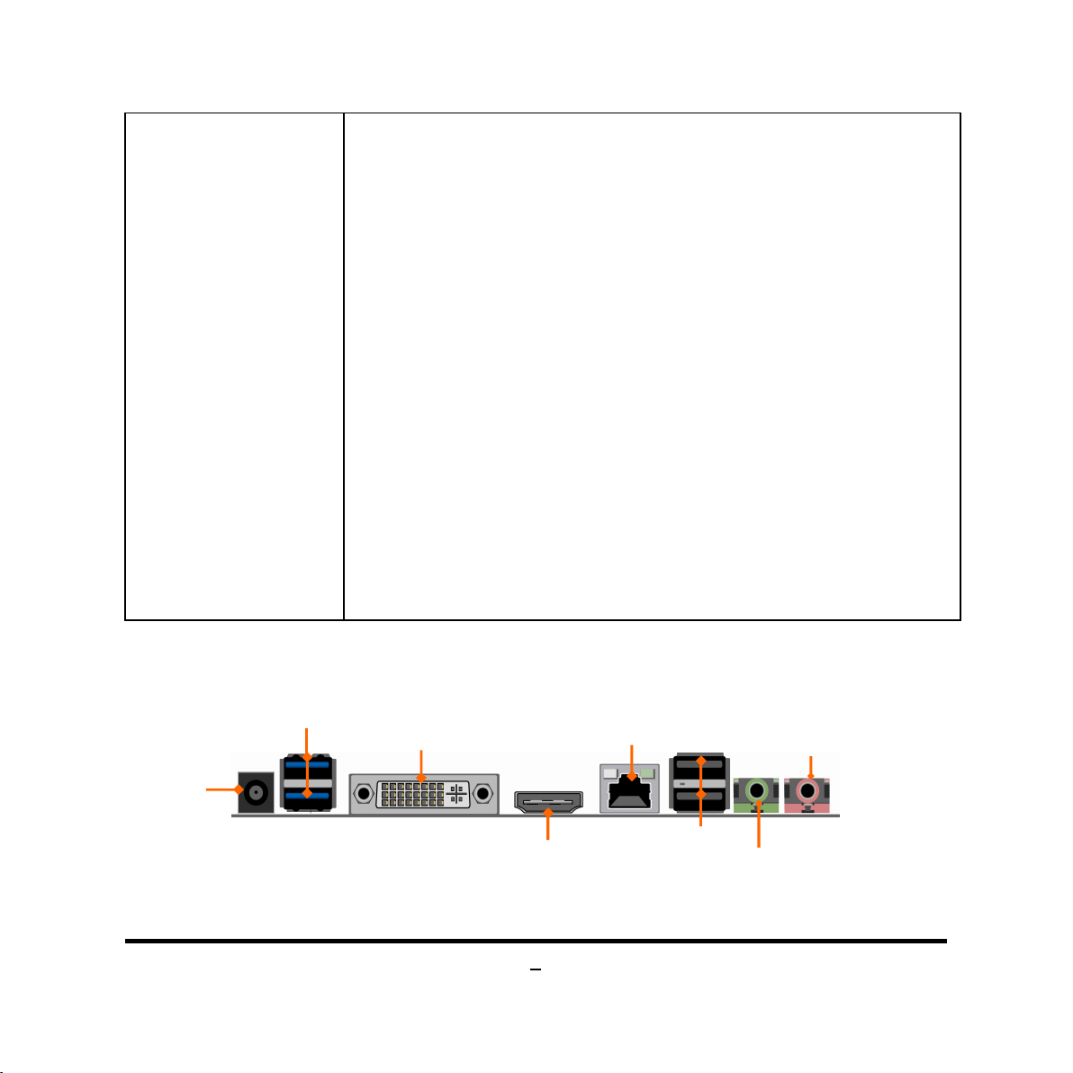
1-3 Layout Diagram
Rear IO Diagram
19V DC
Power-in
Jack
USB 3.0 Ports
RJ-45 LAN Port
3
USB 2.0 Ports
Line-OUT
Page 9
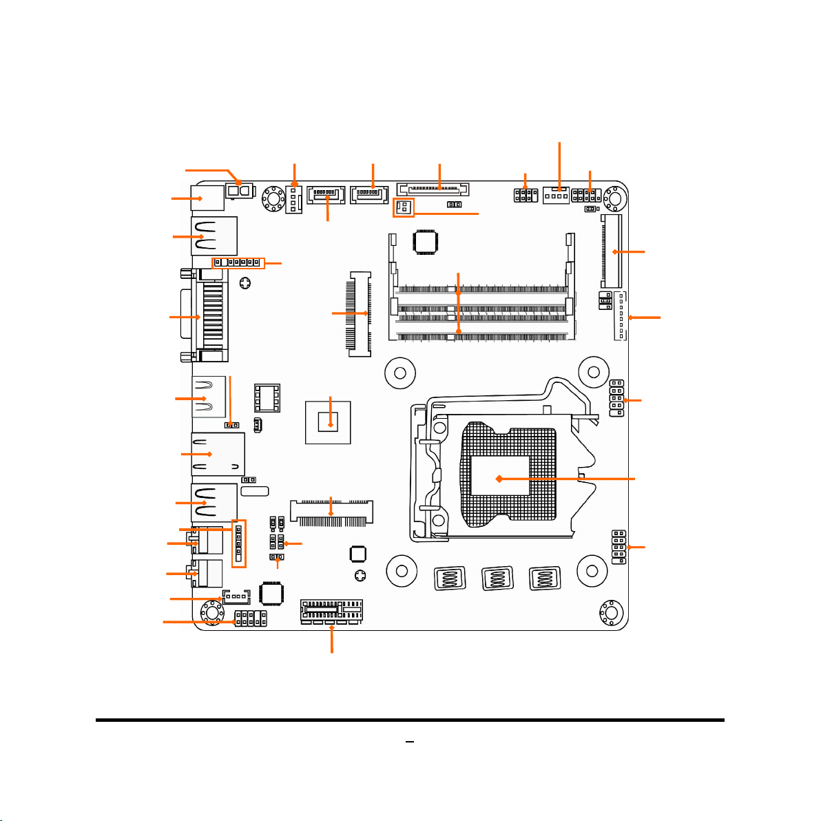
Motherboard Internal Diagram
ATX 19V Power
Intel H81 Chipset
SATAIII Port
(SATA1)
Front Panel
Audio Header
Front Panel
Header
CPUFAN Header
CIR Header
RJ-45 LAN Port
USB 2.0 Port
USB 3.0 Ports
19V DC
Power-in Jack
DVI-I Port
HDMI Port
Line-OUT
MIC-IN
Speaker
Connector
USB 2.0 Header
USB 2.0 Header
48-bit LVDS
LVDS Inverter
DDRIII SODIMM Slots
Mini-PCIE Slot
DMIC Header
SYSFAN Header
PS2 KB & MS Header
SATAII Port
LAN1LED1 Header
BL_LED Header
SATA Power
(SATA_POWER)
Connector
Full-size MSATA Slot
(SATA2)
Connector
MON_SW Header
Connector
Half-size
WIFI_LED Header
Intel LGA1150
CPU Socket
PCI Express x1 slot
4
Page 10
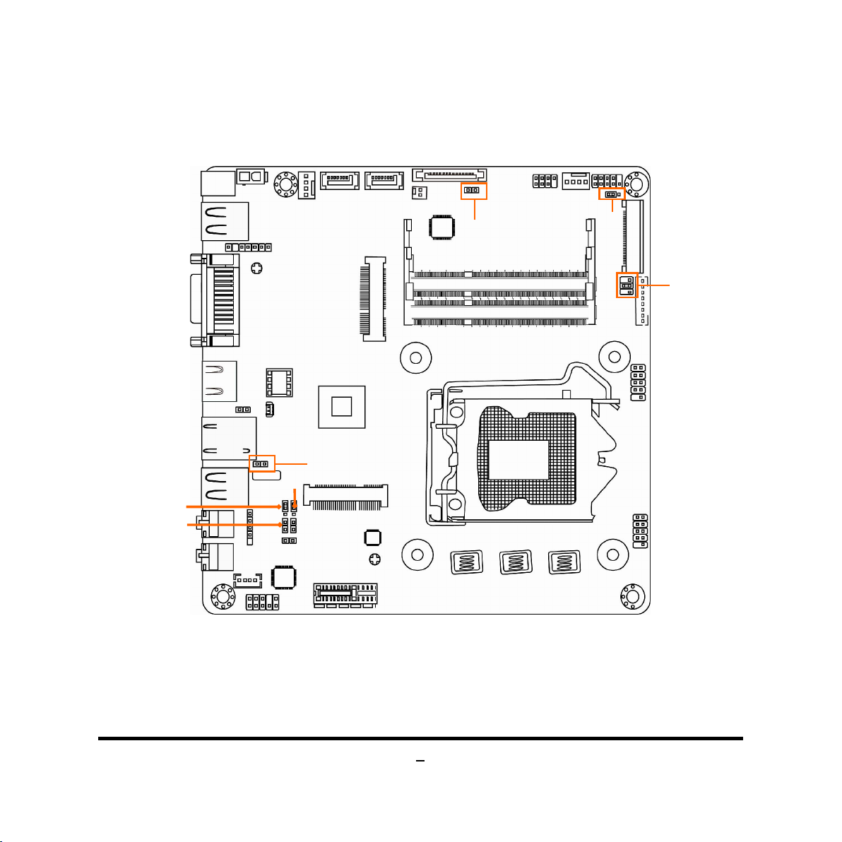
Motherboard Jumper Position
COPEN
JP3
JP4
JBAT
JP5
JP1
JP2
5
Page 11

6
Connectors
Connector
Name
Front Panel Header(PWR LED/
DC_IN DC Adapter 19V
ATX2P DC19V Power Connector
USB1 USB 3.0 Connector X2
DVI-I DVI-I Connector
HDMI High-Definition Multimedia Interface
LAN RJ-45 LAN Connector
USB3 USB 2.0 Connector X2
FP_HP Front Panel Head Phone Connector
FP_MIC Front Panel MIC Connector
SATA_POWER SATA Power Connector
SATA1 SATAIII Connector
SATA2 SATAII Connector
SPEAK_CON Speaker Connector
MINI_FULL Full-size MSATA Connector
MINI_HALF Half-size Mini-PCIE Connector
LVDS LVDS Connector
INVERTER Panel Inverter Connector
SYSFAN,CPUFAN FAN Connector X2
Headers
Header Name Description
FP_AUDIO Front Panel Audio Header 9-pin Block
DMIC_CON DMIC Header 4-pin Block
F_USB1/F_USB2 USB Header X2 9-pin Block
INVERTER Panel Inverter connector 8-pin Block
JW_FP
CIR_CON CIR Header 7-pin Block
MON_SW Monitor Switch Header 2-pin Block
9-pin Block
HD LED/Power Button /Reset)
Page 12
7
PS2KBMS PS2 Keyboard & Mouse Header 6-pin Block
3
LAN1LED1 LAN Activity LED Header 2-pin Block
WIFI_LED WIFI Activity LED Header 2-pin Block
BL_LED Blue Tooth Activity LED Header 2-pin Block
Jumper
Jumper Name Description
JP1 Inverter VCC 12V/19V Select 3-pin Block
JP2 LCD Power Source Setting 4-pin Block
JP4 MINI_ HALF Slot VCC 3.3V/ 3.3VSB Select 3-pin Block
JBAT CMOS RAM Clear Function Select 3-pin Block
COPEN1
Case Open Message Display Function
2-pin Block
Chapter 2
Hardware Installation
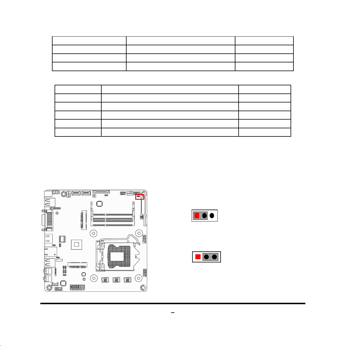
2-1 Jumper Setting
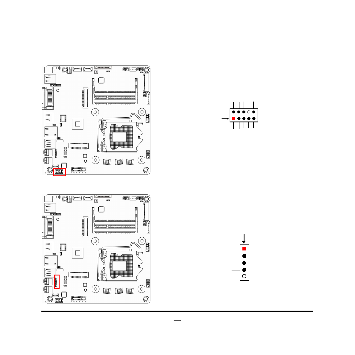
(2) JP1 (3-pin): INVERTER VCC 12V/19V Select
JP1→INVERTER VCC
1
1-2 Closed: Inverter VCC= 12V;
1
2-3 Closed: Inverter VCC= 19V.
Page 13
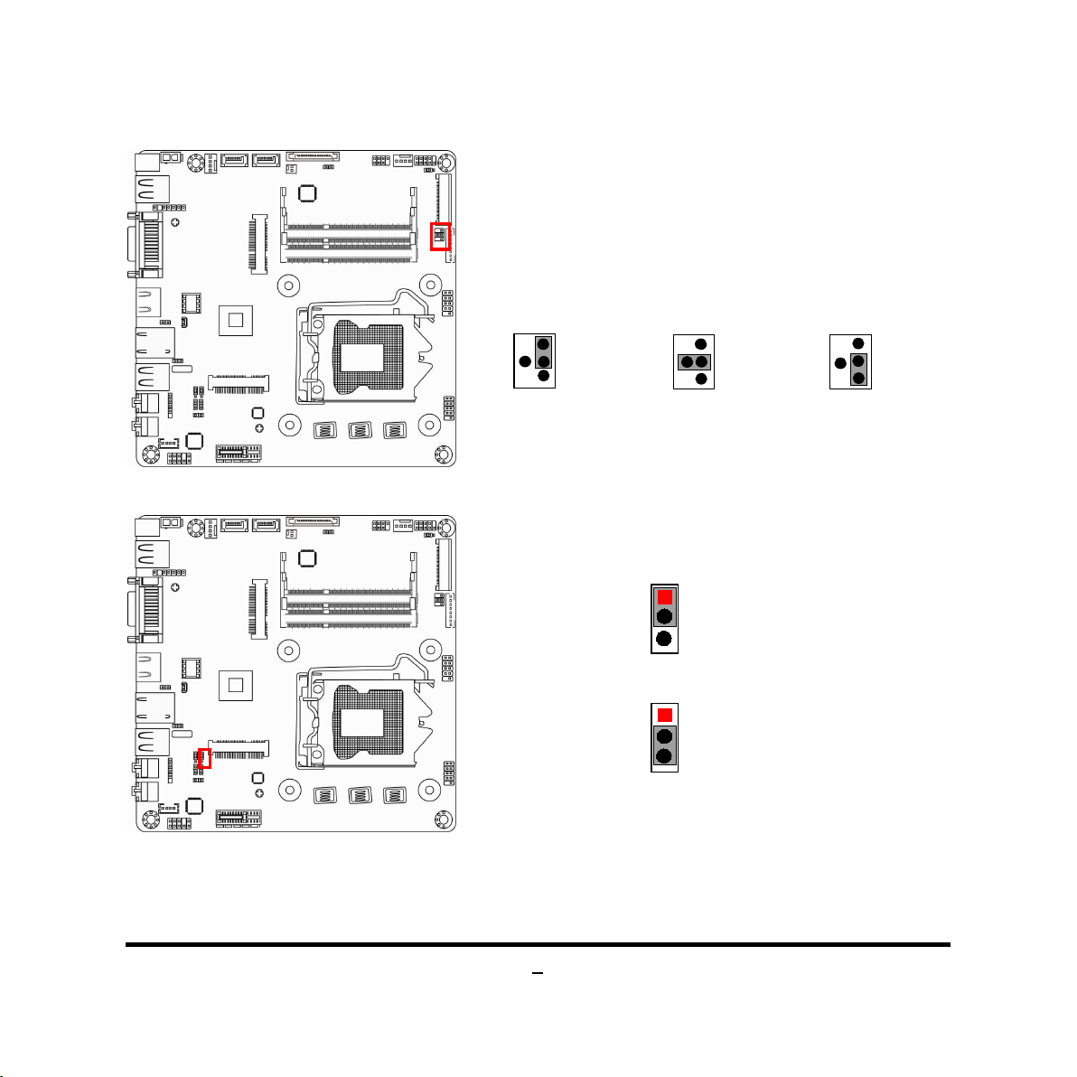
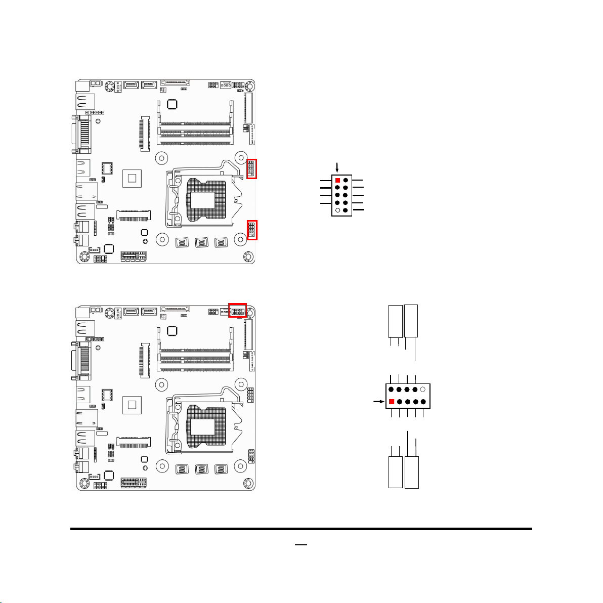
(2) JP2 (4-pin): LCD Power Source Setting
JP2→LVDS Backlight VCC
1
3
5
2-4 Closed: LVDS
VCC= 3.3V;
2
4
6
1
3
5
3-4 Closed: LVDS
VCC= 5V;
(3) JP4 (3-pin): MINI_HALF Slot VCC3.3V/ 3.3VSB Select
JP4→MINI_HALF Slot VCC
1
3
1-2 Closed: MINI_HALF Slot VCC= 3.3V;
1
3
2-3 Closed: MINI_HALF Slot VCC=3.3VSB.
2
4
6
1
3
5
4-6 Closed: LVDS
VCC= 12V.
2
4
6
8
Page 14

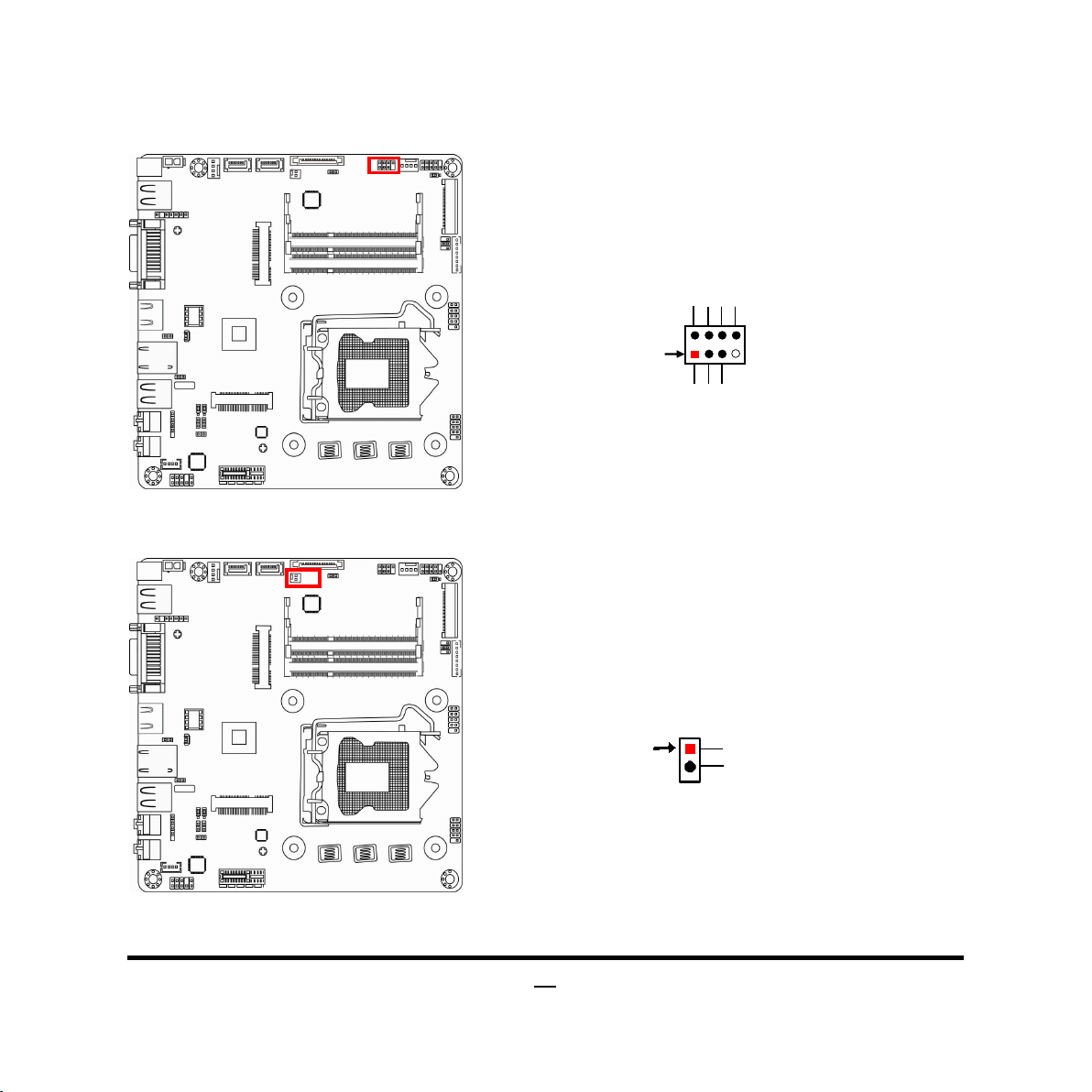
(4) JBAT (3-pin): Clear CMOS Function Setting
Case open function
GND
JBAT
1
3
1
3
1-2 Closed: Normal;
CMOS Clear Setting
2-3 Closed:Clear CMOS.
(5)COPEN1 (2-pin): Case Open Message Display Function Select
COPEN1
1
2
Pin 1-2 Closed: When Case open function pin short to GND, The Case open function
was detected. When Used, needs to enter BIOS and enable ‘Case Open Detect’
function. In this case if your case is removed, next time when you restart your
computer , a message will be displayed on screen to inform you of this.
9
Page 15

2-2 Connectors and Headers
MIC-IN
DVI-I Port
HDMI Port
2-2-1 Connectors
(1) Rear Panel Connectors
19V DC
Power-in
Jack
USB 3.0 Ports
RJ-45 LAN Port
USB 2.0 Ports
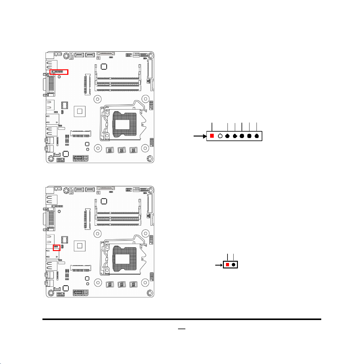
(2) ATX2P (2-pin block): ATX19V Type power connector
Pin1
Pin No. Definition
1 GND
2 +19V
Line-OUT
10
Page 16
(3) SATA_POWER (15-pin block): SATA power connector
SA TA P ow er C on ne ctor
Pin NO.
Definition
Pin 1
Pin 1 3.3V
Pin 2 3.3V
Pin 3 3.3V
Pin 4 GND1
Pin 5 GND1
Pin 6 GND1
Pin 7 +5V
Pin 8 +5V
Pin 9 +5V
Pin 10 GND2
Pin 11 NC
Pin 12 GND2
Pin 13 +12V
Pin 14 +12V
Pin 15 +12V
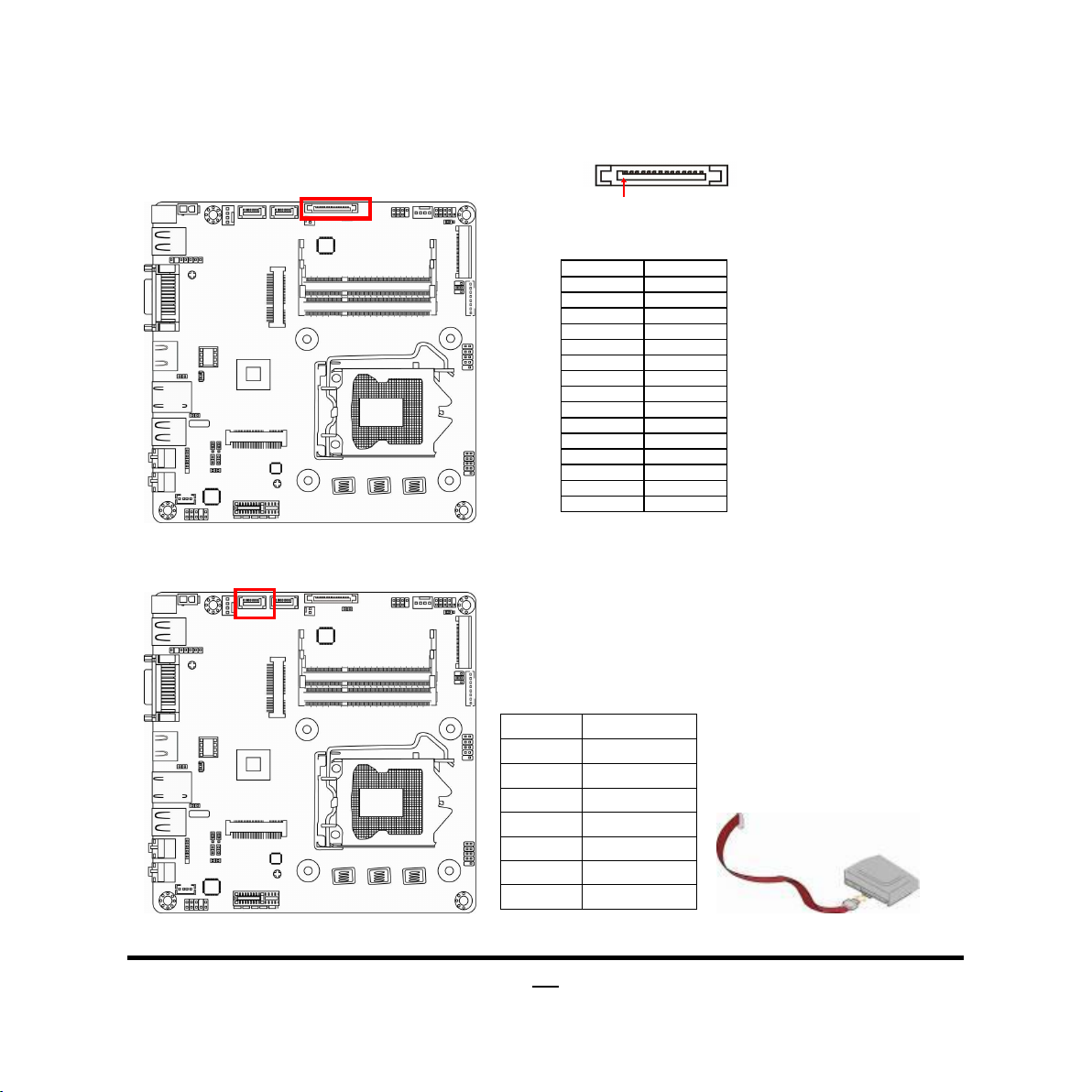
(4) SATA1 (7-pin): SATA III Port connector
This connector is a high-speed SATAIII port that supports 6 GB/s transfer rate.
Pin No. Defnition
1 GND
2 TXP
3 TXN
4 GND
5 RXN
6 RXP
7 GND
11
Page 17
(5) SATA2(7-pin): SATA II Port connector
Pin No.
Definition
This connector is a fast-speed SATAII port that supports 3 GB/s transfer rate.
Pin No. Defnition
1 GND
2 TXP
3 TXN
4 GND
5 RXN
6 RXP
7 GND
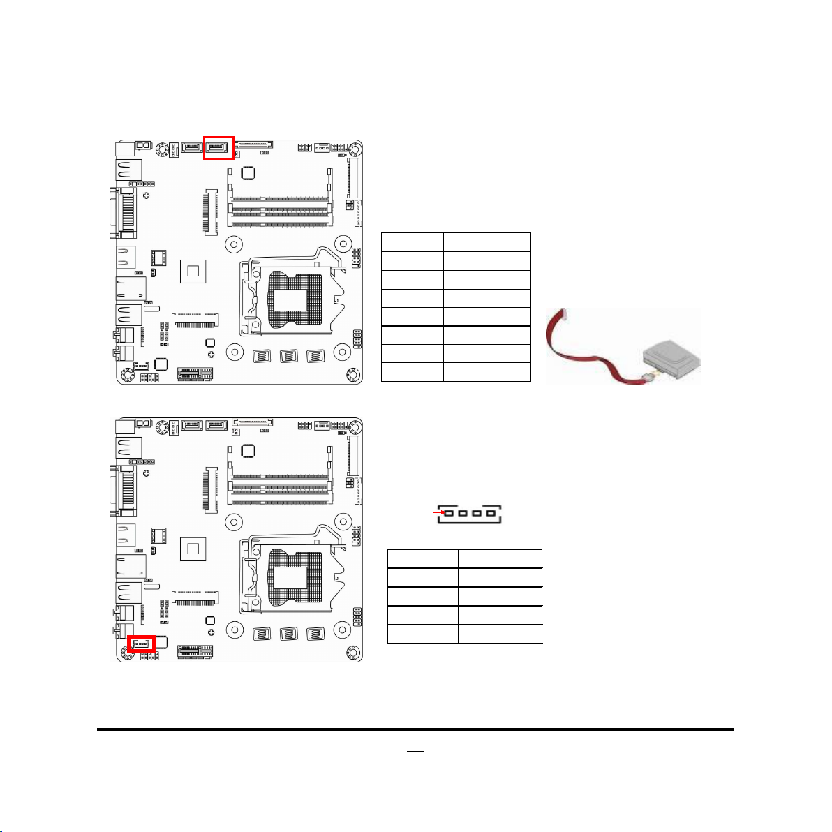
(6)SPEAK_CON (4-pin block): Speaker Connector
Pin 1
SP EAK _CO N
1 L-
2 L+
3 R+
4 R-
12
Page 18
(7) LVDS(40-pin): 48-bit LVDS Header
Pin NO.
Pin Define
Pin NO.
Pin Define
Pin 1 LVDSA_DATAP3 Pin 2 LVDSA_DATAN3
Pin 3 LVDSA_DATAP2 Pin 4 LVDSA_DATAN2
Pin 5 LVDSA_DATAP1 Pin 6 LVDSA_DATAN1
Pin 7 LVDSA_DATAP0 Pin 8 LVDSA_DATAN0
Pin 9 LVDSB_DATAP3 Pin 10 LVDSB _DATAN3
Pin 11 LVDSB_DATAP2 Pin 12 LVDSB _DATAN2
Pin 13 LVDSB_DATAP1 Pin 14 LVDSB _DATAN1
Pin 15 LVDSB_DATAP0 Pin 16 LVDSB _DATAN0
Pin 17 GND Pin 18 LCD_VCC
Pin 19 LCD_VCC Pin 20 LCD_VCC
Pin 21 NC Pin 22 EDID_3V3
Pin 23 GND Pin 24 GND
Pin 25 GND Pin 26 LVDS_CLKAP
Pin 27 LVDS_CLKAN Pin 28 GND
Pin 29 GND Pin 30 GND
Pin 31 LVDS_DDC_CLK Pin 32 LCD_BKLT_EN
Pin 33 LCD_BKLT_PWM Pin 34 LVDS_CLKBP
Pin 35 LVDS_CLKBN Pin 36 BKLT_PWR
Pin 37 BKLT_PWR Pin 38 BKLT_PWR
Pin 39 NC Pin 40 LVDS_DDC_DATA
13
Page 19

(8) INVERTER (8-pin): LVDS Inverter Connector
Pin1
GND
Fan Clock
Control
+12V Fan Power
Pin1
GND
+12V Fan Power
Fan Clock
Conrol
Pin 1
(9) CPUFAN/SYSFAN (4-pin): Fan Connector
Pin No. Definition
1 Backlight Enab le
2 Backlight Duty
3 PVCC
4 PVCC
5 GND
6 GND
7 Backlight +SW
8 Backlight -SW
SYSFAN
CPUFAN
14
Page 20
2-2-2 Headers
MIC2-L
GND
JD
LINE2 RTU
VCC3
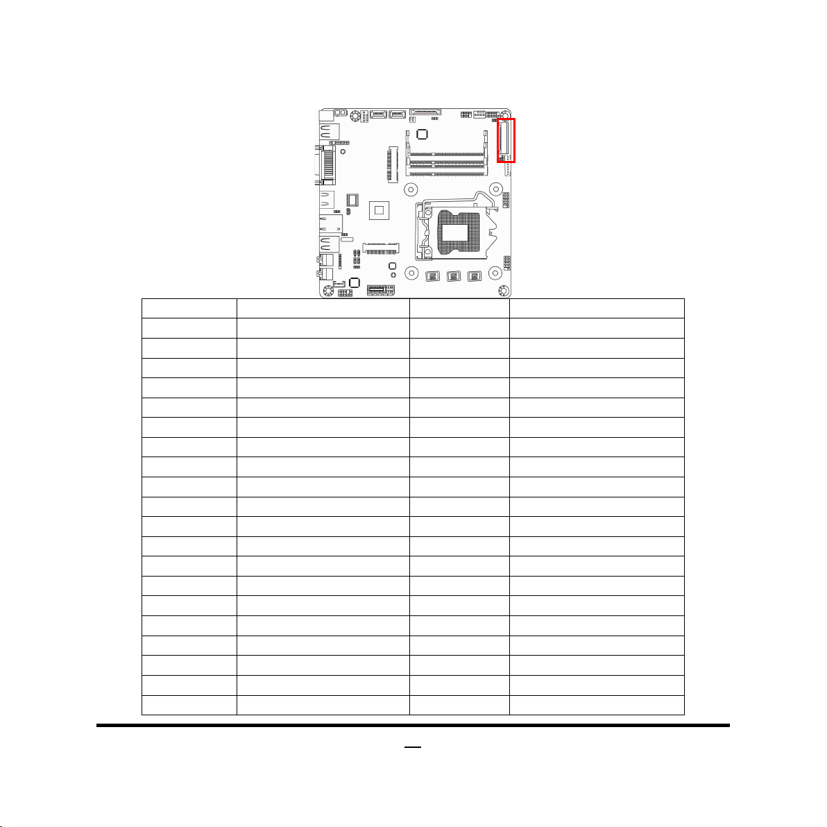
(1) FP_AUDIO (9-pin): Line-Out, MIC-In Header
This header connects to Front Panel Line-out, MIC-In connector with cable.
MIC2 RTU
AUD_
(2) DMIC_CON (4-Pin): DMIC Header
FP_AUDIO
Pin 1
Line-Out, MIC Headers
DMIC_DATA
DMIC_CLK
2
GND
MIC2-R
Pin 1
LINEOUT2-L
LINEOUUT2-R
SENSE
15
Page 21
16
(3)F_USB1/F_USB2 (9-pin): USB 2.0 Port Headers
VCC
NC
+DATA
-DATA
VCC
GND
GND
+DATA
-DATA
RESET
HDDLED+
GND
HDDLED-
VCC
PWRBT
Pin 1
F_USB1/F_USB2 Header
(4) JW-FP (9-pin): Front Panel Header
JW_FP
PWR LED
PWRBTN
PWRLED+
PWRLED-
2
Pin 1
GND
RSTSW
HDLED
Page 22
17
(5) CIR_CON (7-Pin): CIR Header
CIR LED
VCC
Pin 1
1
LVDS Display on/off
CIR _WB
CIR RX
2
NC
ATX 5VSB
GND
(6) MON_SW (2-Pin): Monitor Switch Header
CIR Header
Pin
GND
MON_SW Header
Page 23
(7) PS2KBMS (6-pin): PS/2 Keyboard & Mouse Header
GND
KB_DATA
MS_DATA
VCC
MS_CLK
Pin1
LANLED+
LANLED-
Pin1
(8) LAN1_LED1 (2-pin): LAN Activity LED Header
KB_CLK
LAN1_LED1 Header
18
Page 24

(9) WIFI_LED (2-pin): WIFI Activity LED Header
Pin1
WIFI_LED+
WIFI_LED-
1
Blue Tooth LED+
WIFI_LED Header
(10) BL_LED (2-pin): Blue Tooth Activity LED Header
Pin
Blue Tooth LED -
BL_LED Header
19
Page 25

Chapter 3
Introducing BIOS
Notice! The BIOS options in this manual are for reference only. Different
configurations may lead to difference in BIOS screen and BIOS screens
in manuals are usually the first BIOS version when the board is released
and may be different from your purchased motherboard. Users are
welcome to download the latest BIOS version form our official website.
The BIOS is a program located on a Flash Memory on the motherboard. This program
is a bridge between motherboard and operating system. When you start the computer,
the BIOS program will gain control. The BIOS first operates an auto-diagnostic test
called POST (power on self test) for all the necessary hardware, it detects the entire
hardware device and configures the parameters of the hardware synchronization.
Only when these tasks are completed done it gives up control of the computer to
operating system (OS). Since the BIOS is the only channel for hardware and software
to communicate, it is the key factor for system stability, and in ensuring that your
system performance as its best.
3-1 Entering Setup
Power on the computer and by pressing <Del> immediately allows you to enter Setup.
If the message disappears before your respond and you still wish to enter Setup,
restart the system to try again by turning it OFF then ON or pressing the “RESET”
button on the system case. You may also restart by simultaneously pressing <Ctrl>,
<Alt> and <Delete> keys. If you do not press the keys at the correct time and the
system does not boot, an error message will be displayed and you will again be asked
to
Press <Del> to enter Setup
20
Page 26

3-2 BIOS Menu Screen
Menu Bar
Menu Items
The following diagram show a general BIOS menu screen:
General Help Items
Current Setting Value
Function Keys
BIOS Menu Screen
3-3 Function Keys
In the above BIOS Setup main menu of, you can see several options. We will explain
these options step by step in the following pages of this chapter, but let us first see a
short description of the function keys you may use here:
Press (left, right) to select screen;
Press (up, down) to choose, in the main menu, the option you want to confirm
or to modify.
21
Page 27

Press <Enter> to select.
Press <+>/<–> keys when you want to modify the BIOS parameters for the active
option.
[F1]: General help.
[F2]: Previous value.
[F3]: Optimized defaults.
[F4]: Save & Exit.
Press [Esc] to quit the BIOS Setup.
3-4 Getting Help
Main Menu
The on-line description of the highlighted setup function is displayed at the top right
corner the screen.
Status Page Setup Menu/Option Page Setup Menu
Press [F1] to pop up a small help window that describes the appropriate keys to use
and the possible selections for the highlighted item. To exit the Help Window, press
[Esc].
3-5 Menu Bar
There are six menu bars on top of BIOS screen:
Main To change system basic configuration
Advanced To change system advanced configuration
Chipset To change chipset configuration
Boot To change boot settings
Security Password settings
Save & Exit Save setting, loading and exit options.
User can press the right or left arrow key on the keyboard to switch from menu bar.
The selected one is highlighted.
22
Page 28

3-6 Main Menu
Main menu screen includes some basic system information. Highlight the item and
then use the <+> or <-> and numerical keyboard keys to select the value you want in
each item.
Select Language
This item is for user to choose the system default language.
System Date
Set the date. Please use [TAB] to switch between data elements.
System Time
Set the time. Please use [TAB] to switch between time elements.
23
Page 29

3-7 Advanced Menu
CPU Configuration
Press [Enter] user can have a view of CPU basic information and make settings in
sub-items.
Limit CPUID Maximum
The optional settings are: [Disabled]; [Enabled].
This item should be set as [Disabled] for Windows XP.
Execute Disable Bit
The optional settings are: [Disabled]; [Enabled].
Intel Virtualization Technology
The optional settings: [Enabled]; [Disabled].
When set as [Enabled], a VHM can utilize the additional hardware capabilities
provided by Vanderpool Technology.
24
Page 30

Hardware Prefetcher
Use this item to enabled or disable the Mid Level Cache (L2) streamer prefetcher.
Adjacent Cache Line Prefetch
Use this item to enabled or disable prefetching of adjacent cache lines.
EIST
Use this item to enable or disable Intel Speed Step.
The optional settings are: [Disabled]; [Enabled].
SATA Configuration
SATA Controller (s)
Use this item to enable or disable SATA devices.
The optional settings are: [Disabled]; [Enabled].
SATA Mode Selection
The optional settings are: [IDE]; [AHCI].
SATA Controller Speed
This item indicates the maximum speed the SATA controller can support.
The optional settings are: [Default]; [Gen1]; [Gen2]; [Gen3].
Serial ATA Port1 / Serial ATA Port2/m-SATA
The available running disk name will show on the screen. User can choose to
enable or disable the available SATA port function and choose SATA device type.
PCH-FW Configuration
Use this item to configure Management Engine Technology parameters.
Firmware Update Configuration
Press [Enter] to enable or disable ‘ME-FW Image Re-Flash function’.
USB Configuration
Legacy USB Support
The optional settings are: [Auto]; [Disabled]; [Enabled].
XHCI Hand-off
The optional settings are: [Disabled]; [Enabled].
EHCI Hand-off
The optional settings are: [Disabled]; [Enabled].
USB Mass Storage Driver Support
The optional settings are: [Disabled]; [Enabled].
25
Page 31

26
USB Transfer time-out
Use this item to set the time-out value for control, bulk, and interrupt transfers.
The optional settings are: [1 sec]; [5 sec]; [10 sec]; [20 sec].
Device reset time-out
Use this item to set USB mass storage device start unit command time-out.
The optional settings are: [10 sec]; [20 sec]; [30 sec]; [40 sec].
Device power-up delay
Use this item to set maximum time the device will take before it properly reports
itself to the host controller. ‘Auto’ uses default value: for a root port it is 100 ms, for
a hub port the delay is taken from hub descriptor. The optional settings: [Auto];
[Manual].Select [Manual] you can set value for the following sub-item: Device
Power-up delay in seconds, the delay range in from 1 to 40 seconds in one
second increments.
Super IO Configuration
Super IO Configuration
CIR Controller
Use this item to enable or disable CIR function.
The optional settings are: [Disabled]; [Enabled].
-Device Settings
The current device setting for serial port will show on the screen. When CIR
Controller is set as [Disabled] this item will not appear.
-Change Settings
Use this item to select an optimal setting for super IO device.
ERP Support
Use this item to enable or disable ERP function for this board. This item should be
set as [Disabled] if you wish to have active all Wake-up functions.
Case Open Warning
The optional settings are: [Disabled]; [Enabled].
PS2 KB/MS Wake-UP from S3
*This item is shown when ‘ERP Support’ is set as [Enabled].
PS2 KB/MS Wake-UP is affected by ERP Function in S4-S5. Please disable ERP
before activating this function in S4-S5.
The optional settings are: [Disabled]; [Enabled].
Page 32

PS2 KB/MS Wake-UP from S3-S5
*This item will only show when ‘ERP Support’ is set as [Disabled].
PS2 KB/MS Wake-UP is affected by ERP Function in S4-S5. Please disable ERP
before activating this function in S4-S5.
The optional settings are: [Disabled]; [Enabled].
WatchDog Timer
The optional settings are: [Disabled]; [Enabled].
Use this item to enable or disable WatchDog Timer Control. When set as
[Enabled], the following sub-items shall appear:
WatchDog Timer Value
User can set a value in the range of [10] to [255].
WatchDog Timer Unit
The optional settings are: [Sec.]; [Min.].
WatchDog Wake-up Timer in ERP
The optional settings are: [Disabled]; [Enabled].
This item support WDT wake-up while ERP function is enabled.
When set as [Enabled], the following sub-items shall appear:
WatchDog Timer Value in ERP
The optional setting ranges: [10] ~ [4095] seconds; [1] ~ [4095] minutes.
WatchDog Timer Unit
The optional settings are: [Sec.]; [Min.].
PC Health Status
Press [Enter] to view hardware health status, set SMARTFAN configuration and
select system shutdown temperature.
SmartFan Configuration
Use this item to select CPUFAN smart mode and SYSFAN smart mode. When set
as [Enabled], Use can set full-speed temperature, full-speed duty, idle-speed
temperature and idle-speed duty for CPUFAN or SYSFAN specifically.
CPUFAN /SYSFAN Smart Mode
The optional settings are: [Enabled]; [Disabled].
When set as [Enabled], the following sub-items shall appear:
CPUFAN / SYSFAN Full-Speed Temperature
27
Page 33

Use this item to set CPUFAN/SYSFAN full speed temperature. Fan will run at full
speed when above this temperature.
CPUFAN / SYSFAN Full-Speed Duty
Use this item to set CPUFAN/ SYSFAN full speed duty. Fan will run at full speed
when above the pre-set duty.
CPUFAN / SYSFANIdle-Speed Temperature
Use this item to set CPUFAN/ SYSFAN idle speed temperature. Fan will run at idle
speed when below this temperature.
CPUFAN / SYSFAN Idle-Speed Duty
Use this item to set CPUFAN/ SYSFAN idle speed duty. Fan will run at idle speed
when below the pre-set duty.
Shutdown Temperature Configuration
Use this item to select system shutdown temperature.
The optional settings are: [Disabled]; [70oC/156 oF]; [75 oC/164 o F]; [80 oC/172 oF];
[85 oC/180 oF]; [90 oC/188 oF].
CPUFAN Type
The default setting value is [4-Pin].
SYSFAN Type
The optional settings are: [3-Pin]; [4-Pin].
Network Stack
Press [Enter] to go to ‘Network Stack’ to enable or disable UEFI network stack.
Network Stack
The optional settings are: [Disabled]; [Enabled].
When set as [Enabled], the following sub-items shall appear:
Ipv4 PXE Support
The optional settings are: [Disabled]; [Enabled].
Use this item to enable Ipv4 PXE Boot Support. When set as [Disabled], Ipv4 boot
optional will not be created.
Ipv6 PXE Support
The optional settings are: [Disabled]; [Enabled].
Use this item to enable Ipv6 PXE Boot Support. When set as [Disabled], Ipv4 boot
optional will not be created.
28
Page 34

S3-S5 RTC Wake-up Settings
This item is for user to enable the system wake on RTC alarm from S3-S5.
RTC alarm is affected by ERP
function in S4-S5. Please disable ERP before activating RTC alarm in S4-S5.
Wake-up System with Fixed Time
Use this item to enable or disable system wake-up by RTC alarm. When set as
[Enabled], system will wake on the hour/min/sec specified.
When set as [Enabled], the following sub-items shall appear:
Wake-up hour
The setting range: [0] ~ [23].
Wake-up Minute
The setting range: [0] ~ [59].
Wake-up Second
The setting range: [0] ~ [59].
Wake-up System with Dynamic Time
Use this item to enable or disable system wake-up by RTC alarm. When set as
[Enabled], system will wake on the current time + increased mimute(s).
When set as [Enabled], the following sub-item shall appear:
Wake-up Time Increase
The setting range: [0] ~ [5] munites.
Intel(R) Ethernet Configuration I217LM-XX: XX: XX: XX: XX: XX
Use this item to configure gigabit Ethernet device parameters.
Press [Enter] to view current configuration and make further settings in available
item:
NIC Configuration
This item is for user to configure boot protocol, wake on LAN, link speed, and
VLAN.
Press [Enter] to go to next screen and user can make further settings in following 2
items:
Link Speed
This item specifies the port speed used for the selected boot protocol.
The optional settings are: [Auto Negotiated]; [10 Mbps Half]; [10 Mbps Full];
29
Page 35
[100 Mbps Half]; [10 Mbps Full].
Wake On LAN
Use this item to enable the server to be powered on using an in-band magic
packet.
The optional settings are: [Disabled]; [Enabled].
Blink LEDs
This item identifies the physical network port by blinking the associated LED.
Driver Health
This item provides Health Status for the Drivers/Controllers. User can press [Enter]
to have check current health status.
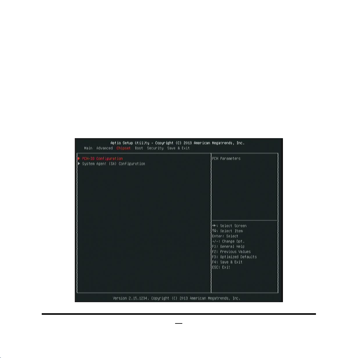
3-8 Chipset Menu
30
Page 36

PCH-IO Configuration
Press [Enter] to make further settings for PCH parameters.
PCIE Slot
The optional settings are: [Disabled]; [Enabled].
PCIE Slot Speed
The optional settings are: [Auto]; [Gen1]; [Gen2].
Detect Non-Compliance Device
Use this item to detect non-compliance PCI Express device. When set as
[Enabled], it will take more time at POST time.
The optional settings are: [Disabled]; [Enabled].
PCH LAN Controller
Use this item to enable or disable onboard NIC.
The optional settings are: [Enabled]; [Disabled].
Mini PCIE Slot
The optional settings are: [Disabled]; [Enabled].
Mini PCIE Speed
The optional settings are: [Auto]; [Gen1]; [Gen2].
Detect Non-Compliance Device
Use this item to detect non-compliance PCI Express device. When set as
[Enabled], it will take more time at POST time.
Azalia
The optional settings are: [Disabled]; [Enabled].
Use this item to control detection of the Azalia device.
USB Configuration
Press [Enter] to further setting USB port configuration.
XHCI Mode
Use this item to select mode of operation for XHCI controller.
The optional settings are: [Smart Auto]; [Disabled].
*When set as [Disabled], the following sub-items shall appear:
EHCI1/EHCI2
The optional settings are: [Disabled]; [Enabled].
Use this item to control USB EHCI (USB 2.0) functions. One EHCI controller must
31
Page 37

always be enabled.
USB0/USB1 Wake-up from S3-S4
*This item will only show when ‘ERP Support’ is set as [Disabled].
The optional settings are: [Disabled]; [Enabled].
USB wake up is affected by ERP function in S4. Please disable ERP before
activating this function in S4.
USB2/USB3 Wake-up from S3-S4
*This item will only show when ‘ERP Support’ is set as [Disabled].
The optional settings are: [Disabled]; [Enabled].
USB wake up is affected by ERP function in S4. Please disable ERP before
activating this function in S4.
System State after Power Loss
Use this item to select AC power state when power is re-applied after a power
failure. The optional settings are: [Always Off]; [Always On]; [Former State].
System Agent (SA) Configuration
Graphics Configuration
Press [Enter] to further setting graphics configuration.
Aperture Size
The optional settings are: [128MB]; [256MB]; [512MB].
DVMT Pre-Allocated
Use this item to select DVMT 5.0 pre-allocated (fixed) graphics memory size used
by the internal graphics device.
The optional settings are: [32M]; [64M]; [96M]; [128M]; [160M]; [192M]; [224M];
[256M]; [288M]; [320M]; [352M]; [384M]; [416M]; [448M]; [480M]; [512M]; [1024M].
DVMT Total Gfx Mem
Use this item to select DVMT 5.0 total graphics memory size used by the internal
graphics device.
The optional settings are: [128MB]; [256MB]; [MAX].
Primary IGFX Boot Display
Use this item to select the video device which will be activated during POST. This
has no effect if external graphics present. 'Secondary boot display selection will
appear based on your selection. VGA modes will be supported only on primary
32
Page 38

display.
The optional settings are: [VBIOS Default]; [DVI]; [HDMI].
Secondary IGFX Boot Display
The optional settings are: [Disabled]; [DVI]; [HDMI].
*The optional setting [HDMI] will only show up when ‘Primary IGFX Boot Display’
is set as [DVI].
DVI to CRT Dongle Support
The optional settings are: [Disabled]; [Enabled].
Active LFP
Use this item to select the Active LEP Configuration.
The optional settings are: [No LVDS]; [LVDS].
When set as [LVDS], use can make further settings in the following 2 items:
LVDS Panel Type:
Use this item to manually select LVDS panel type.
The optional setting are: [640 x 480 18-bit]; [800x 600 18-bit]; [1024 x 600 18-bit];
[1024 x 768 24-bit]; [1280 x 720 18-bit]; [800 x 480 18-bit]; [1366 x 768 18-bit];
[1440 x 900 18-bit]; [1366 x 768 24-bit]; [1440 x 900 24-bit]; [1280 x 1024
24-bit];[1440 x 1050 24-bit]; [1600 x 900 24-bit]; [1680 x 1050 24-bit]; [1600 x 1200
24-bit]; [1920 x 1080 24-bit].
Backlight Control
The optional settings are: [PWM Inverted]; [PWM Normal]; [GMBus Inverted];
[GMBus Normal].
Memory Configuration
This item is for user to press [Enter] to view current memory configuration.
33
Page 39
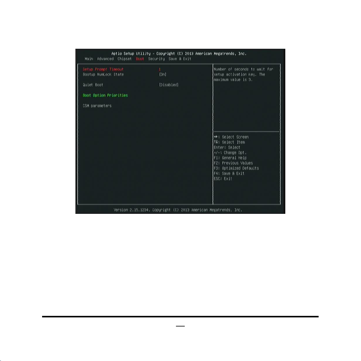
3-9 Boot Menu
Boot Configuration
Setup Prompt Timeout
Use this item to set number of seconds to wait for setup activation key.
Bootup Numlock State
Use this item to select keyboard numlock state.
The optional settings are: [On]; [Off].
Quiet Boot
The optional settings are: [Enabled]; [Disabled].
Boot Option Priorities
Boot Option #1
Use this item to decide system boot order from available options.
34
Page 40

CSM parameters
Press [Enter] to make settings for the following sub-items:
Boot option filter
This option controls what device system can boot to.
The optional settings are: [UEFI and Legacy]; [Legacy only]; [UEFI only].
Launch PXE OpROM policy
This option controls the execution of UEFI and Legacy PXE OpROM.
The optional settings are: [Do not launch]; [UEFI only]; [Legacy only].
Launch Storage OpROM policy
This option controls the execution of UEFI and Legacy Storage OpROM.
The optional settings are: [Do not launch]; [UEFI only]; [Legacy only].
Other PCI device ROM priority
This item is for PCI devices other than Network, Mass storage or video defines
which OpROM to launch.
The optional settings are: [UEFI OpROM]; [Legacy OpROM].
35
Page 41
36
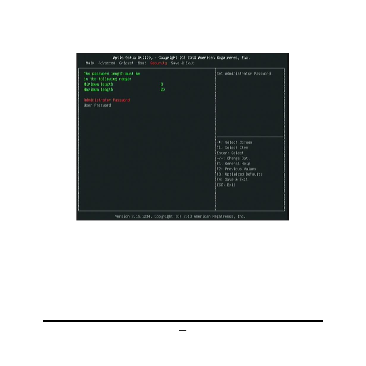
3-10 Security Menu
Security menu allow users to change administrator password and user password
settings.
Page 42

3-11 Save & Exit Menu
Save Changes and Reset
This item allows user to reset the system after saving the changes.
Discard Changes and Reset
This item allows user to reset the system without saving any changes.
Save Changes
This item allows user to save changes done so far to any of the setup options.
Discard Changes
This item allows user to discard changes done so far to any of the setup options.
Restore Defaults
Use this item to restore /Load default values for all the setup options.
37
Page 43

Save as User Defaults
Use this item to save the changes done so far as user defaults.
Restore User Defaults
Use this item to restore defaults to all the setup options.
38
 Loading...