

JET JSH-275-10, JSH-550-10, JSH-275-15, JSH-275-20, JSH-550-15 Operating Instructions and Parts Manual
...
Operating Instructions and Parts Manual
JSH Series Electric Chain Hoists
Models JSH-275, JSH-550
Model JSH‐550 shown
WALTER MEIER (Manufacturing) Inc.
427 New Sanford Road
LaVergne, Tennessee 37086 Part No. M-110100
Ph.: 800-274-6848 Revision A1 06/2010
www.waltermeier.com Copyright © 2010 Walte r Meier (Man ufacturing) Inc.

Warranty and Service
Walter Meier (Manufacturing) Inc., warrants every product it sells. If one of our tools needs service or repair, one of
our Authorized Service Centers located throughout the United States can give you quick service. In most cases, any
of these Walter Meier Authorized Service Centers can authorize warranty repair, assist you in obtaining parts, or
®
perform routine maintenance and major repair on your JET
your area call 1-800-274-6848.
MORE INFORMATION
Walter Meier is consistently adding new products to the line. For complete, up-to-date product information, check with
your local Walter Meier distributor, or visit waltermeier.com.
WARRANTY
JET products carry a limited warranty which varies in duration based upon the product (MW = Metalworking, WW =
Woodworking).
WHAT IS COVERED?
This warranty covers any defects in workmanship or materials subject to the exceptions stated below. Cutting tools,
abrasives and other consumables are excluded from warranty coverage.
WHO IS COVERED?
This warranty covers only the initial purchaser of the product.
WHAT IS THE PERIOD OF COVERAGE?
The general JET warranty lasts for the time period specified in the product literature of each product.
WHAT IS NOT COVERED?
Five Year Warranties do not cover woodworking (WW) products used for commercial, industrial or educational
purposes. Woodworking products with Five Year Warranties that are used for commercial, industrial or education
purposes revert to a One Year Warranty. This warranty does not cover defects due directly or indirectly to misuse,
abuse, negligence or accidents, normal wear-and-tear, improper repair or alterations, or lack of maintenance.
HOW TO GET SERVICE
The product or part must be returned for examination, postage prepaid, to a location designated by us. For the name
of the location nearest you, please call 1-800-274-6848.
You must provide proof of initial purchase date and an explanation of the complaint must accompany the
merchandise. If our inspection discloses a defect, we will repair or replace the product, or refund the purchase price,
at our option. We will return the repaired product or replacement at our expense unless it is determined by us that
there is no defect, or that the defect resulted from causes not within the scope of our warranty in which case we will,
at your direction, dispose of or return the product. In the event you choose to have the product returned, you will be
responsible for the shipping and handling costs of the return.
HOW STATE LAW APPLIES
This warranty gives you specific legal rights; you may also have other rights which vary from state to state.
LIMITATIONS ON THIS WARRANTY
WALTER MEIER (MANUFACTURING) INC., LIMITS ALL IMPLIED WARRANTIES TO THE PERIOD OF THE
LIMITED WARRANTY FOR EACH PRODUCT. EXCEPT AS STATED HEREIN, ANY IMPLIED WARRANTIES OR
MERCHANTABILITY AND FITNESS ARE EXCLUDED. SOME STATES DO NOT ALLOW LIMITATIONS ON HOW
LONG THE IMPLIED WARRANTY LASTS, SO THE ABOVE LIMITATION MAY NOT APPLY TO YOU.
WALTER MEIER SHALL IN NO EVENT BE LIABLE FOR DEATH, INJURIES TO PERSONS OR PROPERTY, OR
FOR INCIDENTAL, CONTINGENT, SPECI AL, OR CONSEQUENTIAL DAMAGES ARISING FROM THE USE OF
OUR PRODUCTS. SOME STATES DO NOT ALLOW THE EXCLUSION OR LIMITATION OF INCIDENTAL OR
CONSEQUENTIAL DAMAGES, SO THE ABOVE LIMITATION OR EXCLUSION MAY NOT APPLY TO YOU.
Walter Meier sells through distributors only. The specifications in Walter Meier catalogs are given as general
information and are not binding. Members of Walter Meier reserve the right to effect at any time, without prior notice,
those alterations to parts, fittings, and accessory equipment which they may deem necessary for any reason
whatsoever. JET® branded produc ts are not sold in Canada by Walter Meier.
tools. For the name of an Authorized Service Center in
2

Table of Contents
Warranty and Servic e .............................................................................................................................. 2
Table of Contents .................................................................................................................................... 3
Introduction ............................................................................................................................................. 6
Desc ription .............................................................................................................................................. 6
Specifica tions .......................................................................................................................................... 7
Unpac king ............................................................................................................................................... 8
Contents of the Shipping Container.......................................................................................................... 8
Installation and Assembly ........................................................................................................................ 8
Electric al Connec tions ............................................................................................................................. 8
Grounding Instr uc tions ............................................................................................................................. 8
Extension Cords ...................................................................................................................................... 9
Installing Chain Container ........................................................................................................................ 9
Pre-Operation Inspection ....................................................................................................................... 10
Limit Sw itch In spectio n .......................................................................................................................... 1 0
Inspecting the Load Chain ..................................................................................................................... 10
Inspecting the Hooks ............................................................................................................................. 11
Operating the Hoist ................................................................................................................................ 12
Maintenance .......................................................................................................................................... 13
Brake Inspection .................................................................................................................................... 13
Lubrication............................................................................................................................................. 13
Replacing Load Chain ........................................................................................................................... 14
How to Cut Chains ................................................................................................................................. 1 4
Making a C-Link .................................................................................................................................... 1 4
Single Fall Chain Hoist .......................................................................................................................... 14
Vertical and Hori z ontal Links.................................................................................................................. 15
Dual Fall Chain Hoists ........................................................................................................................... 15
Inspection and Maintenance .................................................................................................................. 16
Inspection Schedule A ........................................................................................................................... 16
Inspection Schedule B ........................................................................................................................... 16
Troubleshooting ..................................................................................................................................... 17
Replacement Parts ................................................................................................................................ 18
Parts Breakdown for JSH Series Electric Chain Hoists ........................................................................... 19
Parts List for JSH Series Electric Chain Hoists ....................................................................................... 20
Electric al Connec tions – JSH Series Hoists ........................................................................................... 23
3

1. Read and understand the entire owner’s manual befor e att em pting assembly or operation.
2. Read and understand the warnings po sted on the m achine and i n thi s manual. Failur e to comply wit h
all of these warnings m ay cause seriou s i njury.
3. Replace the warning labels if they become obscured or removed.
4. This chain hoist is designed and intended for use by properl y trained and experienced personnel only.
If you are not f amiliar with t he proper and safe oper ation of a chain hoi st, do not use until proper
training and knowledge have been obtained.
5. Do not use this chai n hoist for other than it s intended use. If used for other purpo ses, Walt er Meier
(Manufactur ing) Inc., di sclaims any real or implied warranty and hol ds itself harmless from any injur y
that may result from that use.
6. Do not install this chai n hoist where explosive hazards may exist.
7. Give your work undivided attenti on. Looking around, carrying on a conversati on and “horse-play” are
careless acts that can result in serious injury.
8. Do not use to lift peopl e, or loads over people. Warn others in the vici nity when lifting or transporting a
load. Avoid swingi ng load and hook.
9. Make certain t he pathway for a moving load is free of all obstructions.
10. Do not leave a suspended load unattended.
11. Do not ex c eed the rated load limit of the chain hoist.
12. Make sure l imi t switches are operat i ng properl y. Do not use lim it switches as routi ne operat ing stop s;
they are emergency dev ic es onl y .
13. Do not use the loading limit device to measure a l oad.
14. Do not use the load chain to wrap around the load or as a sling.
15. Maintain firm footi ng when operating the hoist.
16. Before lifting a load, mak e sure chai n is seated i n c hain wheels or sprockets.
17. Always inspect the chai n hoi st f or dam age prior t o use. Do not use a chai n hoist wit h twisted, ki nked,
worn or other wise damaged chain. If the chain hoi st is damaged, do not use until it has been repaired
or replaced.
18. Do not use more than one c hain hoist to l ift or move a load. If this is unav oidable, each chai n hoist
must have the same capaci ty as the load to be moved.
19. Do not use when bi nding causes an unequal load distr ibut ion on the supporting chai ns.
20. Never allow the l oad chai n to “set” ov er sharp edges. A ll lif ts must be m ade wit h strai ght chain that is
free of obstacl es.
21. Do not use a chain hoist unless load is centered bet ween top and bottom hooks.
22. P rotect load c hain from weld spl atter and other contami nants. Do not all ow the hook or chai n to be
contacted by a live wel ding electrode.
23. Do not permit chain or hook to be used as a ground when welding.
24. Do not u se the hoist f or lif ting guided l oads, such as elev ators and dumbwait ers. The se appli cations
require additional protective devi c es which are not incorporated into this hoist.
25. Always take time to study the job to be performed and choose the safest method. Do not place
yourself or other people in an unsafe position.
26. Do not attempt to repair a damaged load chai n or l engthen t he c hain.
27. Replace the chain with factor y replacement chain only. Do not use any other t y pe of chain.
4

28. Use only r ec ommended lubricant when needed.
29. Never use the chai n hoist if either hook i s stretched, def ormed, or has a broken or mi ssing safety
latch. Always replace the safety latch and/or the hook before placing the chain hoist back int o servic e.
30. Leave all internal maintenance to a qualified Walter Meier service center.
31. Do not oper ate this hoist while tired or under the influence of drugs, alcohol or any medic ation.
32. Understand and follow all procedures as set forth in American National Standards (ANSI), titled
“Performanc e Standar d for Electric Chain Hoist, ” ANSI/ASM E HST- 1M.
Familiarize yourself with the following safety notice s used in this manual:
This means that if precautions are not heeded, it may result in minor injury
and/or possible machine damage.
fatal injury .
This means that if precautions are not heeded, it may result in serious or even
5

Introduction
This manual is provided by Walter Meier (Manufacturing) Inc., covering the safe operation and
maintenance procedures for the JET Model JSH Series Electric Chain Hoists. This manual contains
instructions on installation, safety precautions, general operating procedures, maintenance instructions
and parts breakdown. This hoist has been designed and constructed to provide years of trouble free
operation if used i n accordance with instructi ons set forth i n this manual. If there are any questions or
comments, pl ease contact either your local supplier or Walter Meier. Walt er M eier can also be reac hed at
our web site: www.waltermeier.com.
Description
The JSH Series Elect ric Hoists are portable, rugged hoists construct ed of sturdy but lightweight die cast
aluminum alloy housings. A transmission with heat-treated alloy steel gears provides reliable service.
Operation is activated with one hand using pushbutton controls on a pendant cord, keeping the other
hand free to gui de t he load. A m agnet ic di sc brake en sures rapi d stop and secure hol di ng of l oads. Thi s
hoist is designed and tested in accordance with the American Society of Mechanical Engineers Code
B30.16, “Saf ety Standar d for Overhead Hoists.”
Read and understand the entire contents of this manual before attempting set-up or operation!
Failure to compl y may cause seri ou s in ju ry.
Record your purchase information here for quic k ref er ence:
Model No.: Stock No.: Serial No.:
Purchased From : Date Purchased:
Date Installed: Installer:
6

Specifications
Figure 1
Model No. JSH-275-10 JSH-275-15 JSH-275-20 JSH-550-10 JSH-550-15 JSH-550-20
Stock No. 110100 110115 110120 110110 110515 110520
Rated Capacity (Ton) 1/8 1/8 1/8 1/4 1/4 1/4
Standard Lift (ft.) 10 15 20 10 15 20
Hoisting Speed (fpm) 16 16 16 8 8 8
Motor 1/6HP, 115V, 1PH, 60Hz
Rated Amps 3 3 3 3 3 3
Duty Cycle 25% 25% 25% 25% 25% 25%
Duty Cycle Rating H3 H3 H3 H3 H3 H3
No. of Falls 1 1 1 2 2 2
Load Chain ( mm) 4 Dia. x 12 4 Dia. x 12 4 Dia. x 12 4 Dia. x 12 4 Dia. x 12 4 Dia. x 12
Push Button Control
Cord Length (ft.)
Net Weight (lbs.) 30.62 32.38 33.92 34.6 37.22 40.09
Shipping Weight (lbs.) 33.48 35.02 36.78 37.22 40.09 42.95
A 12.09 12.09 12.09 12.09 12.09 12.09
B 6.46 6.46 6.46 6.46 6.46 6.46
C 3.58 3.58 3.58 3.58 3.58 3.58
D 6.81 6.81 6.81 6.81 6.81 6.81
E 2.99 2.99 2.99 3.74 3.74 3.74
F 5.47 5.47 5.47 5.47 5.47 5.47
G 4.72 4.72 4.72 4.72 4.72 4.72
Headroom - H (in.) 15.27 15.27 15.27 17.1 17.1 17.1
6 11 16 6 11 16
Table 1
The above specifications were current at the time this manual was publi shed, but bec ause of our policy of
continuous improvement, Walter Meier (Manufactur ing) Inc., reserves the right to c hange specifications at
any time and without pri or notice, without incurring obligat ions.
7

Unpacking
Lift the hoi st out of the carton by the top hook or
the center secti on. Do not ap ply ex cessiv e for ce
to the motor cover, as damage may result.
Carefully inspect t he hoist for shippi ng damage,
and for loose or missing parts. Report any
damage immediately to your distributor and
shipping agent. Do not discard any shipping
material until the Hoist is installed and running
properly.
Contents of the Shipping Container
1 Hoist
1 Chain Container with Bracket and Fasteners
1 Owner’s Manual
1 Warranty Card
Installation and Assembly
Support for the hoist may be hook, clevis pin,
trolley, or beam clamp. Supporting structures
(such as I-Beams, etc.) should be installed by
properly licensed professional installers.
Whatever method of
suspension is chosen, the support
components must be rated equal to, or
greater than th e capaci t y of the chain ho ist.
Electrical Connections
Electrical connections must
be made by a qualified electrician in
compliance with all relevant codes. This
machine must be properly grounded to help
prevent electrical shock and possible fatal
injury.
This machine’s power cable is installed with a
plug that has an equipm ent-grounding conductor
and a grounding pro ng, sim ilar to that shown in
Figure 3. The plug must be plugged into a
matching outlet that is properly installed and
grounded in accordanc e wit h al l loc al codes and
ordinances. Do not m odif y t he plug – if it will not
fit the outlet, have the proper outlet installed by
a qualified elec tric ian.
Grounding Instructions
This mac hine m ust be grounded. I n the event of
a malfuncti on or break down, groundi ng prov i des
a path of least resi stance f or electric current to
reduce the risk of el ect ri c shock.
Figure 2
Figure 3
8

Improper connection of the equipmentgrounding conductor can result in a risk of
electric shock. The conductor with insulation
having an outer surface that is green with or
without yellow stripes, is the equipmentgrounding conductor . If repair or replac em ent of
the electric cord or plug is necessary, do not
connect the equi pm ent-grounding conductor to a
live terminal.
Check with a qualified electrician or service
personnel if the grounding instructions are not
completely understood, or if in doubt as to
whether the tool is properly grounded.
Repair or replace a damaged or worn cord
immediately.
Make sure the voltage of your power supply
matches the specif ications on the nam e plat e of
the hoist.
Extens ion Cords
If an extension c or d is necessary, mak e sure t he
cord rating is suit able for the am perage listed on
the hoist’s nam e plate. An undersized cord will
cause a drop in line volt age resulting in loss of
power and overheating.
Use the chart in Fi gure 4 as a general guide in
choosing the cor rect size cord. If in doubt, use
the next heavi er gauge. The smaller the gauge
number, the heavier the cord.
Recomm end ed Ga ug es (A WG ) of Extensi on Co rd s
Extension Cord Length *
25
50
75
100
150
200
Amps
< 5 16 16 16 14 12 12
5 to 8 16 16 14 12 10 NR
8 to 12 14 14 12 10 NR NR
12 to 15 12 12 10 10 NR NR
15 to 20 10 10 10 NR NR NR
21 to 30 10 NR NR NR NR NR
feet
feet
feet
feet
feet
feet
Installing Chain Container
Do not overfill chain
container. If chain should overfill and begin
to fall, th e entire chain container may empty
without warning, resulting in serious
personal injury or property damage.
To assemble the chai n c ontainer to the hoist:
1. Hang hoist in position on the I-Beam or
trolley. Do not install chain container yet.
Allow slack side and load side of chain to
hang freely from hoist.
2. Apply power to the hoist and press the
DOWN butt on until the l ower limit switch is
tripped.
3. Check the chain c ontainer to ensure that the
seam is inside the bag. The bag must not be
inside out. The forks of the bracket are
inserted into the slots in the bag, which is
then secured by closing the two selfadhesive flaps (see Figure 5).
*based on li mi ti ng th e lin e voltage drop to 5V at 150% of the
rated amp eres.
NR: Not Recommended.
Figure 4
Figure 5
9

4. Remove the screw and washer holding the
end chain to the hoist ( Figure 6). Mount the
bracket of the chain container in that
location as shown in Figur e 7.
5. Put the chai n stop into the container (Fi gure
7), and operate the hoist to bring the load
hook up until the upper limit switch is
tripped.
6. Check the chain to e nsure that all the nonloaded chain is completely in the container.
Do not put chain into the
chain container by hand! By not following
the above steps, the chain can become
twisted or kinked and can damage the hoist.
Pre-Operation Inspection
Limit Switch Inspection
1. Press UP button.
2. While the hook moves up, raise the limit
switch paddle where the chain enters the
hoist.
Figure 6
3. Hook should immediately stop.
4. Check DOWN limit switch in similar manner.
Inspecting the Load Chain
Clean the chain with a solvent, and carefully
inspect the enti re load chain. The chain should
be visually checked before each day’s use.
Replace damaged c hain before using the chai n
hoist.
Replace the load chain if any of the following are
identified:
1. Seriously r usted or c r acked.
2. Marks on the chai n surfac e are deeper than
5% of the link’s diamet er.
3. Links are twisted or def ormed.
4. The link s are stretched too l ong or seriously
worn on the surf ace, especial l y at the poi nts
where links contact each other. To check
the links for str etch, pr oc eed as f ollows:
5. Select an unworn, un-stretched length of
chain (at t he slack end f or ex ampl e). Let t he
chain hang verti cally wit h a light load (about
20 pounds) on the chain to pull it taut .
Figure 7
10

6. Use a large caliper t o measure the outside
length of a convenient number of links.
Measure the same num ber of links in a used
section of chain and calculate the
percentage increase in length of the worn
chain.
7. If the l ength of the worn chai n is m ore than
1-1/2% longer than the unused chain, then
the chain should be repl aced. I f t he chain is
worn less than 1-1/2%, check it at several
more places along it s length. If any section
is worn more than 1-1/2%, the chain should
be replaced.
Never extend load chain by welding a second
piece to the origi nal.
Do not operate the hoi st wi t h
a twisted, kinked or damaged load chain. Do
not splice the load chain .
Check that the chain does not twist along its
length from hoist to hook. If twist is present on
units with multiple falls, the hook must be
passed back through the chain loop to remove
all twist in the chain.
The lo ad chain supplied with
your JET chain hoist is designed,
manufactured, and tested for proper fit and
durability. Over a period of time, the chain
may need to be replaced. For your own
safety, use factory replacement chain only.
Use of other th an factory replacement chain
may cause serious injury and/or damage to
the hoist.
Inspecting the Hooks
It is im por tant to check t op and bottom hooks for
proper opening and other signs of deformation
or damage. Repl ace a hook immediately if any
of the following problems are identified:
1. The safety latch no longer cont ac ts the hook
opening.
2. The vertical angle at the neck of the hook
reaches 10° (see Figure 8).
3. Chemical corr osi on or crack s on the hook .
4. Excessive wear on the inside surface.
5. The throat opening has enl arged wider than
the maxim um permissible 10% incr ease, as
shown in Figure 9.
Figure 8
HOIST CAPACITY TOP HOOK and BOTTOM HOOK
X-Normal X-Limit
1/8 Ton 0.906 inches 1 inch
1/4 Ton 0.906 inches 1 inch
NOTE: Maximum permissible throat opening of hook with
latch fully retracted.
Figure 9
11

NOTE: Excessive hook throat opening or twist
indicates abuse or overloading of the hoist. If
such deformation is discovered, inspect hoist,
chain and all supporting m embers very c arefully
for additional indications of excessive hoist
loading.
Do not attempt repair of a
hook by heat treating, bending or attaching
anything by welding. Such procedures will
weaken and may cause failu re of the hoo k.
Operating the Hoist
Before beginning a work
shift, an op erator should test t he pushbut ton
station, limit switches and brake control. If
not functioning properly, they should be
replaced or repaired before putting hoist in
service.
Allow the hoist to come to a full stop before
changing direction. Rapidly reversing or
catching a falling load can overload the hoist
system and cause a failure in the hoist and/or
chain, resulting in injury or property damage.
If the hoist is connected to a manual trolley,
move the hoist by pushing on the suspended
load. Move an unl oaded hoist by pull ing on the
empty hook. Do NOT move the hoist by pull ing
on the pendant cord.
The brake mechanism must be kept clean and
free from di rt, water, and oil. Never all ow oil to
penetrate the brake mechanism. Always keep
your hoist clean, and store in a clean, dry
location.
Follow this general procedure for hoisti ng loads:
1. Secure the upper hook to the supporting
structure.
2. Pl ace l oad sli ng or chai n in t he center of t he
bottom hook, m aking sure the saf et y latc h is
secure. Never load the hook in front of
the safety lat ch. See Fi gur e 10.
3. Avoid lifting one load with two hoists. I f this
is unavoidable, apply equal weight to both
hoists and use hoists with the proper lift
capacity. Capacity of each hoist mus t be
equal to the total load to be lifted.
4. Press UP button and remove all slack in
load chain. Increase tension in the load
chain until the hoist is about to raise the
load.
5. Check again that the load is properly slung,
directly under hoist, and will not suddenly
swing or twist.
Figure 10
12

6. Raise load an i nch or two abov e the ground
and stop. Observ e load for a f ew moments,
looking for signs that the load or hoist
system is unstabl e, or other i ndicati ons that
there is a problem.
7. Check that the chain is not twisted at the
bottom hook. All welds should face the
same direction (see Figure 13). For hoists
with two or more falls of chain, make sure
the bottom hook is not turned over. This
may cause the chain to t wist.
8. Raise load to the traveling height. Raise
only to the height necessary t o safely clear
all obstacles.
9. Lower load at destination. If both UP and
DOWN commands must be used during
lowering, pause f or a moment between each
reversal of load di r ect ion.
10. Slowly allow weight to shift from hoist to
ground or new support. Do not approach
load until all tension i s out of chai n and l oad
is stable.
Maintenance
Brake Inspection
Keep brake surface and
lining free of grease.
1. Remove load and disconnect hoist from
power source.
2. Remove the back frame cover (index #31,
page 19).
3. Check for worn brake disc by m easuring t he
brake air gap with a feeler gauge (Figure
11). A brake gap larger than the allowable
wear limit – 0.039” - may cause chatter or
failure to rel ease.
4. If the brake is not operating properly, the
entire brake assembly must be replaced
by qualifi ed servic e per sonnel .
Lubrication
The gear housing has been f ill ed with 1/ 2 pound
of grease at the manufacturer and should not
require attention. If future lubrication becomes
necessary, use approxim ately 3/4 cup of a light
semi-fluid NLGI #1 gr ease.
Wipe the chain clean with a cloth periodically
and apply a light coat of SAE 90 gear oil.
Figure 11
13
Replacin g Loa d Ch ai n
Over time, the load chai n will wear or elongate.
This can cause damage t o the hoist, breakage,
or non-engagement of the load sheave. The
following procedur es descri be repl aci ng the load
chain for single and multiple fall hoists. These
procedures should be performed by
experienced personnel only.
How to Cut Chains
Use a bolt cutter with special cutter jaws for
cutting hardened chai n. Cut only one si de of the
link at a time. When making the second cut,
place a mat over the chain to catch the flying
chain section.
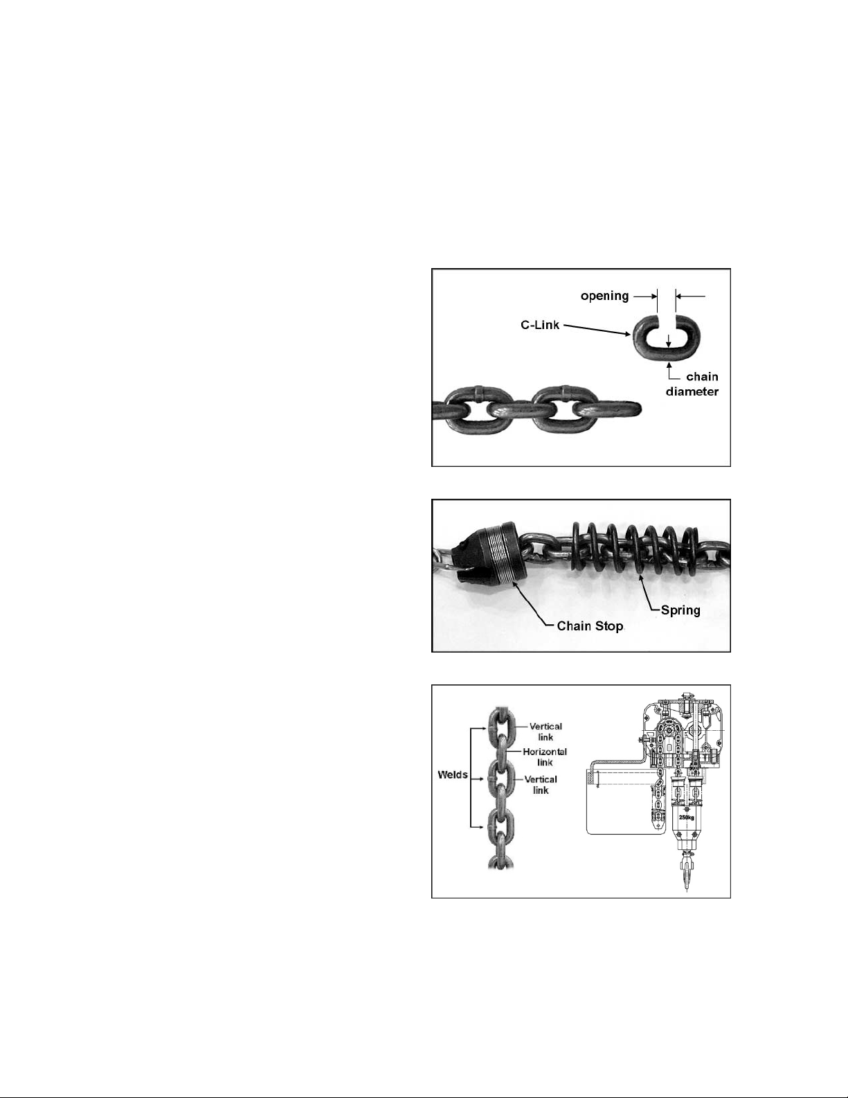
Making a C-Link
Replacing l oad chai n will requi re the use of a Clink (in some cases, two C-links), which you can
easily make as follows:
1. Cut a link from the old chain.
2. Cut the weld from the link leaving an
opening approximately 1.25 times the
diameter of the link mat eri al. See Figure 12.
3. Gr ind the cut areas smooth and remove all
burrs.
Figure 12
Single Fall Chain Hoist
1. Lower the l oad hook unti l onl y 1 to 2 f eet of
slack chain r em ains i n the chain c ontainer.
2. Remove chain cont ainer .
3. On t he slack side of the ol d chain, remove
the chain stop and the spring (Figure 12).
Keep these handy for later re-installing.
4. Using a C-l i nk, connect the new chain to t he
old chain. Be sure vertical link welds face
away from load sprocket ( see Figur e 14) .
5. Keep t ension on both sides of t he chai n and
lower the load hook to pull the new chain
through the hoist. Do not let the chain twist
or bind as it is being pulled through the
hoist.
6. Stop hoist when 1 to 2 feet of new chain
remains on the slack si de.
7. Install the spri ng and c hain stop on the slack
end of the new chain.
8. Remove C-link. Rem ove the load hook and
the spring from the old chain, and install
them on the new chain. Inspect condition of
both spring and hook.
Figure 13
Figure 14
(dual fall model show n)
14

9. Lower l oad hook until the limit switch stops
hoist movement. Inspect the chain for any
signs of twist.
10. Install chain container following the
instructi ons in this manual. Do not fill chai n
container by hand.
11. It is recommended that after installing new
chain, the fi rst f ew lifts be lim ited t o no more
than 25-50% of the rated load. Thoroughly
inspect chain for twist before placing hoist in
routine servi c e.
Vertical and Horizontal Links
Vertical and hor izontal are det ermined from the
relationship wit h the load sprocket. Vertical link s
will be guided by the center slit in the load
sprocket. Horizontal links will engage in the oval
pockets on the sprocket. See Figure 14.
Dual Fall Chain Hoists
T h e link o n t he lo a d si d e en d
must be a vertical link. If it is a horizontal
link, the chain will have a twist in it.
1. Lower hook until only 1 to 2 feet of slack
chain remains in the chain container.
2. Remove chain cont ainer .
3. On t he slack side of the chain, remove the
chain stop, and remove the spring(s). (see
Figure 13). Keep these handy for later reinstalling.
4. Using a C-link(s), c onnect the new chain to
the old chain. If the end li nk of the old chain
is horizontal , use t wo C-links. I f t he end link
of the old chain is vertical, use one C-link
See Figure 15. Using the correct number of
C-links will properly orient the chain, and
ensure that the first link on the load side end
is a horizontal link .
5. Install the spring(s) and chain stop on the
opposite end of the new chain.
6. Support the l oad hook so that t he load chain
can pass through the chain sheaves
smoothly.
7. Press the DOW N button to move the chain
through the hoist. Keep t ension on the chai n
as you pull i t through to the l oad side, until
the C-link(s) clears the hoist at the load
side.
8. Feed the new chain thr ough t he load hook .
Figure 15
9. Rem ove the clevis pin from t he suspension
block (#48, page 19), and remove the old
chain.
10. Remove C-link and connect the end of the
new chain to the su sp ension block, usi ng the
clevis pin and a new cott er pin to secure it.
Do not substitute any other pin or bolt in
this application.
NOTE: Be sure that there is no twisting of
chain between last chain sprocket in the
hoist and the suspension bloc k .
11. Install chain container following instructions
in this manual . Do not fill chai n container by
hand.
12. Lower hook until limit switch stops hoist
movement, t hen raise hook until lim it switch
stops hoist m ovement. Inspect chain for any
signs of twist and cor r ect before continuing.
13. It i s recomm ended that the fi rst few l ifts be
limited to no m ore than 25-50% of the rated
load. Inspect chain for twist before placing
hoist into routine serv ice.
15

Inspection and Maintenance
All repairs and adjustments are to be performed by trained and experienced
personnel using procedures that are approved for the hoist system being serviced. All safetyrelated defici encies discovered in the inspection are to be corrected b efore hoist is placed back
into service. Check f or internal damage whenever external d amage h as occu rred.
Read and follow the ANSI Inspection and Maintenance instructions. Know the meaning of Frequent
Inspection, P eriodic Inspecti on, Normal Servic e, Heavy Service, and Severe Service. It is the customer’s
responsibili ty to understand and follow all ANSI and J ET inspect ion and maintenance instr uc tions.
The following i tems are to be i nspected by appoi nted personnel at the tim e interval noted bel ow. Dated
inspection and repair reports must be maintained. Copies of all reports must be available to service
personnel.
Inspection Schedule A
Service Interval:
Normal Service – Monthl y
Heavy Service – Weekly to Monthl y
Severe Service – Daily to Weekl y
1. Check brake for slippage.
2. Check that pushbutton controls operate
properly.
3. Check that limit switches function properly.
Without load, oper ate up button control whil e
observing stopper spring. If stopper spring
becomes compressed and motor does not
stop, STOP operation immediately. Limit
switch is not oper ating proper ly. Repeat t est
with down button control.
4. Check top hook and load hook for
deformati on, chemical damage, and cracks.
5. Check that load chain is clean and lightly
lubricated, free of excessive wear or
deformation at the contact points between
links and link and hook. This hoist uses
special alloy hoisting chain and does not
interchange wit h any other manufacturer . All
replacement chain must be purchased f rom
your JET distributor or from Walter Meier
directly by calling 800-274-6848.
6. Check that the chain is untwisted, and
passes through all sprockets sm oothly whil e
under load.
7. Check entire hoist system for signs of
damage and loss of integr it y .
Inspection Schedule B
Service Interval:
Normal Service – Yearly
Heavy Service – Semi-Annually
Severe Service – Qu art erl y
1. Do all of the Schedule A items.
2. Check entire unit for loose screws, bolts,
nuts and pins.
3. Check for evidence of excessive wear,
corrosion, cracks, or distortion in the
following parts: hook parts, chain
attachments, suspension bolts and shafts,
gears, bearings, pins, rollers, and locking
and clamping devi c es.
4. Check f or evidenc e of dam age to hook parts
including hook r etaining nuts and collars and
pins and hook holding f rame and parts used
to secure the frame.
5. Check f or evidenc e of dam age or excessiv e
wear of load gear, sheave and sprocket
wheel. If the pockets are too deep, the chai n
may jam with corresponding failure of
engagement betwee n chain an d sprocket or
sheave.
6. Check for ev idence of excessiv e load brake
wear. Inspect clearance between brake
components, and adjust if needed.
7. Check for evidence of pitting or other
deteriorati on of visible controller c ontacts.
8. Check for evidence of deterioration of
supporting struc tures and trolleys.
9. Check for vi sible deform ation of limit switc h
coil springs.
10. Check that all warning labels are present
and readable.
16

Troubleshooting
Trouble Probable Cause Remedy
Motor will not run.
Hoist lifts very slowly.
Hoist lifts but will not
lower.
Hoist lowers but will
not lift.
Check circuit br eak er s, switc hes and
No incoming power, or low voltage.
Rectifier damaged so that the brake
won’t release.
Motor damaged.
Overloaded. Reduce load.
Low voltage.
Broken conductor in pendant cord.
Up/down switch malfunctioning. Repair or replace switc h.
Overloaded. Reduce load to within hoist capacity.
Up/down switch malfunctioning. Repair or replace switc h.
Brake malfunction.
connections in power supply lines. If
low voltage, hav e certif ied electrician
test incoming power.
Have rectifier replaced by qualified
service per sonnel .
Have motor replaced by a qualif ied
service technician.
Determine cause of low voltage and
bring up to withi n +/- 10% of t he
voltage listed on the hoist nameplate.
Test continuity of each conductor.
Replace cable if needed.
Have brake inspected by qualified
personnel. Replace if needed.
Load continues
drifting down
excessiv ely when
hoist is stopped.
Motor overheat s.
Poor engagement of
chain with
sprocket/sheave.
Brake chatters.
Hoist overloaded. Reduce load to within r ated capacity.
Have a qualifi ed technic ian dis-
Grease or oil on the lining.
Brake disc is worn. Replace brake assembly.
Brake springs are dam aged.
Excessive load or too frequent use.
Brake drags.
Load chain seriously worn. Replace load chain.
Sprocket wheel, sheave or the chain
guide is seriously worn.
Check for greater t han allowable air
gap.
If brake still chat ters after being
replaced check r ectifier for proper
operation.
assemble the brake and cl ean the
lining.
Replace brake spri ngs (qualified
personnel).
Operate within r at ed load and
according to duty cycle rating.
Adjust brake clear anc e ( qualified
personnel).
Replace parts as needed.
Replace brake assembly.
Have rectifier replaced by qualified
service per sonnel .
17

Trouble Probable Cause Remedy
Limit switch failure.
Bad connection of lim it swit c h leads.
Limit switch dam aged. Replace limit switc h.
Inspect the contac ts of the leads and
limit switches.
Replacement Parts
Replacement par ts are li sted on the f ollowing page s. To order par ts or reach our serv i ce departm ent, call
1-800-274-6848, Monday through Friday (see our website for business hours, www.waltermeier.com).
Having the Model Number and Serial Number of your mac hine available when you call will allow us to
serve you quickly and accurately.
18

Parts Breakdown for JSH Series Electric Chain Hoists
19

Parts List for JSH Series Electric Chain Hoists
Index No. Part No. Description Size Qty
1 ............... JSH275-1 .................Capacity Label for JSH-275 ................................................................... 1
................. JSH550-1 .................Capacity Label for JSH- 550 ................................................................... 1
................. TS-1531012 .............Phillips Pan Head Machine Screw ......................M3x6 .......................... 2
................. TS-1550011 .............Plain Washe r ......................................................3mm ........................... 2
2 ............... JHS275-2 .................Socket Head Cap Screw .....................................M6x40 ........................ 2
................. TS-2361061 .............Spring Wash er....................................................6mm ........................... 2
................. TS-1550041 .............Plain Washe r ......................................................6mm ........................... 2
3 ............... JSH275-3 .................Motor Side Cover................................................................................... 1
4 ............... JSH275-4 .................Motor Case Gasket ................................................................................ 1
5 ............... JSH275-5 .................Grooved Ball Bearing..........................................6201 ........................... 1
6 ............... JSH275-6 .................Rotor Assembly ..................................................................................... 1
7 ............... JSH275-7 .................Grooved Ball Bearing..........................................6202 ........................... 1
8 ............... JSH275-8 .................Motor Case Assembly ............................................................................ 1
9 ............... JSH275-9 .................Round Pin ............................................................................................. 4
10 ............. JSH275-10 ...............Self Locking Hex Nut ..........................................M6 .............................. 1
11 ............. JSH275-11 ...............Grooved Ball Bearing..........................................6004 ........................... 2
12 ............. JSH275-12 ...............Chain Guard .......................................................................................... 2
13 ............. JSH275-13 ...............Lift Wheel .............................................................................................. 1
14 ............. JSH275-14 ...............Self Locking Hex Nut ..........................................M8 .............................. 2
15 ............. JSH275-15 ...............Gear Case ............................................................................................. 1
16 ............. JSH275-16 ...............Lift Gear ................................................................................................ 1
17 ............. JSH275-17 ...............Snap Ring ..........................................................18mm ......................... 1
18 ............. JSH275-18 ...............First Gear Shaft ..................................................................................... 1
19 ............. JSH275-19 ...............Grooved Ball Bearing..........................................6000 ........................... 1
20 ............. JSH275-20 ...............Brake Nut .............................................................................................. 1
21 ............. JSH275-21 ...............Snap Ring ..........................................................10mm ......................... 1
22 ............. JSH275-22 ...............Grooved Ball Bearing..........................................6201 ........................... 2
23 ............. JSH275-23 ...............Second Gear Assembly ......................................................................... 1
24 ............. TS-1503061 .............Socket Head Cap Screw .....................................M6x25 ........................ 4
................. TS-2361061 .............Spring Wash er....................................................6mm ........................... 4
................. TS-1550041 .............Plain Washe r ......................................................6mm ........................... 4
25 ............. JSH275-25 ...............Gear Side Gasket .................................................................................. 1
26 ............. JSH275-26 ...............Back Frame ........................................................................................... 1
27 ............. TS-1503061 .............Socket Head Cap Screw .....................................M6x25 ........................ 3
................. TS-2361061 .............Spring Wash er....................................................6mm ........................... 3
................. TS-1550041 .............Plain Washe r ......................................................6mm ........................... 3
28 ............. JSH275-28 ...............Back Frame Gasket ............................................................................... 1
29 ............. JSH275-29 ...............Brake .................................................................................................... 1
30 ............. JSH275-30 ...............Cross Head Pan Screw ......................................M5x65 ........................ 2
................. TS-2361051 .............Spring Wash er....................................................5mm ........................... 2
................. TS-1550031 .............Plain Washe r ......................................................5mm ........................... 2
31 ............. JSH275-31 ...............Back Frame Cover ................................................................................. 1
32 ............. TS-1502091 .............Socket Head Cap Screw .....................................M5x40 ........................ 3
................. TS-2361051 .............Spring Wash er....................................................5mm ........................... 3
................. TS-1550031 .............Plain Washe r ......................................................5mm ........................... 3
................. JSH275-32-3 ............O-Ring................................................................4 x1.8mm .................... 3
33 ............. JSH275-33-10 ..........ID Label for JSH-275-10 ........................................................................ 1
................. JSH275-33-15 ..........ID Label for JSH-275-15 ........................................................................ 1
................. JSH275-33-20 ..........ID Label for JSH-275-20 ........................................................................ 1
................. JSH550-33-10 ..........ID Label for JSH-550-10 ........................................................................ 1
................. JSH550-33-15 ..........ID Label for JSH-550-15 ........................................................................ 1
................. JSH550-33-20 ..........ID Label for JSH-550-20 ........................................................................ 1
................. TS-1531012 .............Phillips Pan Head Machine Screw ......................M3x6 .......................... 4
................. TS-1550011 .............Plain Washe r ......................................................3mm ........................... 4
34 ............. JSH275-34 ...............Load Chain .........................................................Ø4x12m m............ per ft.
35 ............. JSH275-35 ...............Touch Block A ....................................................................................... 2
20

Index No. Part No. Description Size Qty
36 ............. JSH275-36 ...............Limit Spring ........................................................................................... 2
37 ............. JSH275-37 ...............Retainer Ring ........................................................................................ 1
38 ............. JSH275-38 ...............Chain Stop ............................................................................................ 1
39 ............. JSH275-39 ...............Chain Container .................................................................................... 1
40 ............. JSH275-40 ...............Spring Pin.............................................................................................. 2
41 ............. TS-1503061 .............Socket Head Cap Screw .....................................M6x25 ........................ 1
................. TS-2361061 .............Spring Wash er....................................................6mm ........................... 1
................. TS-1550041 .............Plain Washe r ......................................................6mm ........................... 1
42 ............. JSH275-42 ...............Chain Container Bracket ........................................................................ 1
43 ............. JSH275-43 ...............Limit Switch ........................................................................................... 2
................. JSH275-43-1 ............Phillips Pan Head Machine Screw ......................M3x16 ........................ 4
................. TS-2361031 .............Spring Wash er....................................................3mm ........................... 4
................. TS-1550011 .............Plain Washe r ......................................................3mm ........................... 4
44 ............. JSH275-44 ...............Limit Switch As sembly ........................................................................... 1
................. JSH275-44-1 ............Gasket................................................................................................... 1
................. JSH275-44-2 ............Cover .................................................................................................... 1
................. JSH275-44-3 ............Countersunk Cross Head Screw .........................M3x8 .......................... 2
................. JSH275-44-4 ............Insulation Sheet ..................................................................................... 2
................. JSH275-43 ...............Limit Switch ........................................................................................... 2
................. JSH275-43-1 ............Phillips Pan Head Machine Screw ......................M3x16 ........................ 4
................. TS-2361031 .............Spring Wash er....................................................3mm ........................... 4
................. TS-1550011 .............Plain Washe r ......................................................3mm ........................... 4
45 ............. TS-1501081 .............Socket Head Cap Screw .....................................M4x30 ........................ 4
................. TS-2361041 .............Spring Wash er....................................................4mm ........................... 4
................. TS-1550021 .............Plain Washe r ......................................................4mm ........................... 4
46 ............. JSH275-46 ...............Bottom Hook Assembly for JSH-275 ...................................................... 1
46-1 .......... JSH275-46-1 ............Bottom Hook ......................................................................................... 1
46-2 .......... JSH275-46-2 ............Thrust Ball Bearing .............................................8100 ........................... 1
46-3 .......... JSH275-46-3 ............Slotted Hex Nut ..................................................M10 ............................ 1
46-4 .......... JSH275-46-4 ............Spring Pin...........................................................Ø2.5x8mm.................. 1
46-5 .......... JSH275-45-5 ............Socket Head Cap Screw .....................................M5x20 ........................ 2
46-6 .......... JSH275-45-6 ............Bottom Hook Housing ............................................................................ 2
46-7 .......... JSH275-45-7 ............Self Locking Hex Nut ..........................................M5 .............................. 2
46-8 .......... JSH275-46-8 ............Safety Latch Assembly .......................................................................... 1
................. ................................Safety Latch .......................................................................................... 1
................. ................................Double Spring........................................................................................ 1
................. ................................Phillips Pan Head Machine Screw ......................M4x20 ........................ 1
................. ................................Self Locking Hex Nut ..........................................M4 .............................. 1
47 ............. JSH275-47 ...............Top Hook Assembly for JSH-275 ........................................................... 1
47-1 .......... JSH275-47-1 ............Top Hook .............................................................................................. 1
47-2 .......... TS-1504051 .............Socket Head Cap Screw .....................................M8x25 ........................ 2
47-3 .......... JSH275-47-3 ............Countersunk Cross Head Screw .........................M5 x10 ........................ 4
47-4 .......... JSH275-47-4 ............Fixing Board .......................................................................................... 1
47-5 .......... JSH275-47-5 ............Connection Bar for JSH-275 .................................................................. 1
47-6 .......... JSH275-47-6 ............Washe r.................................................................................................. 1
48 ............. JSH550-48 ...............Suspension Chain Block ........................................................................ 1
49 ............. JSH550-49 ...............Clevis Pin .............................................................................................. 1
50 ............. JSH550-50 ...............Cotter Pin ...........................................................Ø2x16mm................... 1
51 ............. JSH550-51 ...............Touch Block B ....................................................................................... 1
52 ............. JSH550-52 ...............Bottom Hook Assembly for JSH-550 ...................................................... 1
52-1 .......... JSH275-32 ...............Socket Head Cap Screw .....................................M5x40 ........................ 1
52-2 .......... JSH275-45-5 ............Socket Head Cap Screw .....................................M5x20 ........................ 2
52-3 .......... JSH275-7 .................Grooved Ball Bearing..........................................6202 ........................... 2
52-4 .......... JSH550-52-4 ............Sheave .................................................................................................. 1
52-5 .......... JSH550-52-5 ............Bottom Hook Housing ............................................................................ 2
52-6 .......... JSH275-45-7 ............Self Locking Hex Nut ..........................................M5 .............................. 3
53 ............. JSH550-53 ...............Top Hook Assembly for JSH-550 ........................................................... 1
21

Index No. Part No. Description Size Qty
53-1 .......... JSH550-53-1 ............Suspension Bolt .................................................................................... 1
53-2 .......... JSH550-53-2 ............Connection Bar for JSH-550 .................................................................. 1
54 ............. JSH275-54 ...............Cable Gland .......................................................................................... 2
55 ............. JSH275-55 ...............Warning Card ........................................................................................ 1
56 ............. JSH275-56 ...............Pushb u tto n Co rd ................................................1 6 AWGx3C ......... per ft.
57 ............. JSH275-57 ...............Pushbutton ............................................................................................ 1
58 ............. JSH275-58 ...............Rectifier ..............................................................50A ............................ 1
59 ............. TS-2284202 .............Phillips Pan Head Machine Screw ......................M4x20 ........................ 1
................. TS-1550021 .............Plain Washe r ......................................................4mm ........................... 1
60 ............. JSH275-60 ...............Housing for Capacitor ............................................................................ 1
61 ............. JSH275-61 ...............Capacitor ............................................................................................... 1
62 ............. JSH275-62 ...............Power Cable Assembly .......................................16AWGx3C ................ 1
22

Electrical Connection s –
JSH Series Hoists
23

WALTER M EIE R (Manufa c turing) Inc.
427 New Sanford Road
LaVergne, Tennessee 37086
Phone: 800-274-6848
www.waltermeier.com
24
 Loading...