

Assembly Instructions
JRBG-14 Roller Bearing Guides
Pre-Assembly
1. Disconnect the saw from the power source,
unplug.
2. It is easier to install the new guides if you
remove the band saw’s table.
3. Remove the circular table insert found on
the top of the table, and also the table pin
found on the side of the table. The table can
be removed by unscrewing the lock knobs
found below the table trunnion.
4. Remove the existing blade guides.
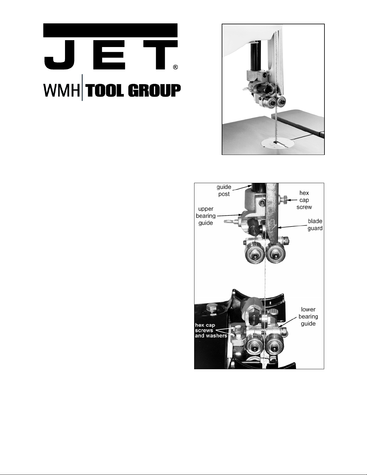
Upper Bearing Guide
Referring to Figure 1:
1. Fit the upper bearing guide onto the guide
post and tighten the hex cap screw.
Note: Model JWBS-14OS Band Saw
requires bushing (Part No. 150214) shown
in G, Fig. 2.
WMH TOOL GROUP
2420 Vantage Drive
Elgin, Illinois 60123 Part No. M-708127
Ph.: 800-274-6848 Revision B 03/06
www.wmhtoolgroup.com Copyright © WMH Tool Group
Figure 1

Referring to Figure 2:
2. Adjust the back-up bearing (Fig. 2) so that it
is 0.003” away from the back of the blade,
about the thickness of a piece of paper. To
make this adjustment loosen thumb screw
(F, Fig. 2) and turn the adjusting screw
(E, Fig. 2) until the adjustment is correct.
Tighten thumb screw (F, Fig. 2).
3. Loosen the thumb screw (C, Fig. 2) and turn
the adjusting screw (D, Fig. 2) until the
bearing guides rest just behind the gullet of
the blade teeth.
4. Loosen the socket head cap screw
(A, Fig. 2) and turn the screw (B, Fig. 2)
clockwise or counter-clockwise until the
side-bearing (Fig. 2) is 0.003” away from the
side of the bearing, about the thickness of a
piece of paper.
5. Adjust the opposite side bearing.
6. Tighten socket head cap screw (A, Fig. 2).
Check to make sure the adjustments have
not changed and the bearing guides do not
pinch the blade.
7. Attach the blade guard.
Lower Bearing Guide
1. Attach the lower bearing guide (Fig. 1) with
two hex cap screws and washers (Fig. 1).
Referring to Figure 3:
2. Adjust the back-up bearing so that it is
0.003” away from the back of the blade,
about the thickness of a piece of paper. To
make this adjustment loosen thumb screw
(A, Fig. 3) and turn the adjusting screw
(B, Fig. 3) until the adjustment is correct.
Tighten thumb screw (A, Fig. 3).
3. Loosen the thumb screw (C, Fig. 3) and turn
the adjusting screw (D, Fig. 3) until the
bearing guides rest just behind the gullet of
the blade teeth.
4. Loosen the socket head cap screw
(E, Fig. 3) and turn the screw (F, Fig. 3)
clockwise or counter-clockwise until the
bearing is 0.003” away from the side of the
bearing, about the thickness of a piece of
paper.
5. Adjust the opposite side bearing.
6. Tighten socket head cap screw (E, Fig. 3).
Check to make sure the adjustments have
not changed and the bearing guides do not
pinch the blade.
Figure 2
Figure 3
 Loading...