


Operating Instructions and Parts Manual
Bench Top Edge Bander
Model JEB-1
WMH TOOL GROUP
2420 Vantage Drive
Elgin, Illinois 60123 Part No. M-708000
Ph.: 800-274-6848 Revision B 12/04
www.wmhtoolgroup.com Copyright © WMH Tool Group
(veneer banding not included)

This manual has been prepared for t he owner and operators of a J ET Model JEB-1 Edge Bander. Its
purpose, aside f rom machine oper ation, is to promot e safety using acc epted operati ng and maint enance
procedures. To obtain maxim um life and effi ciency from y our Edge Bander and to ai d in usi ng it safel y,
please read this manual thoroughly and follow the instructions carefully.
Warranty and Service
WMH Tool Gr oup warrants ever y product it sell s. If one of our tools needs s ervice or repai r, one of our
Authorized Repair St ations located thr oughout the United States can provi de quic k servi c e or information.
In most cases, a WM H Tool Group Repair Station c an as sist in authorizing repair work, obtaining parts, or
perform routi ne or m ajor maintenance repair on your JET pr oduc t.
For the nam e of an A uthoriz ed Repair St ation in your area, pl ease call 1-800-274-6848, or v isit our web
site at www.wmhtoolgroup.com
More Information
Remember, WMH Tool Group i s consistently adding new products to the li ne. For complete, up-to-dat e
product information, check with your local WMH Tool Group distributor, or visit our web site at
www.wmhtoolgroup.com
WMH Tool Group Warranty
WMH Tool Group makes every effort to assure that its products meet high quality and durability standards
and warrants to the original retail consumer/purchaser of our products that each product be free from
defects in mat erials and workmanship as foll ows: 1 YEAR LI MITED WARRANTY ON ALL PRODUCTS
UNLESS SPECIFIED OTHERWISE. This Warranty does not apply to defects due directly or i ndirectly to
misuse, abuse, negl igence or acc idents, norm al wear-and-tear , repair or alterati ons outside our f aciliti es,
or to a lack of maintenanc e.
WMH TOOL GROUP LIMITS ALL IMPLIED WARRANTIES TO THE PERIOD SPECIFIED ABOVE,
BEGINNING FROM THE DATE THE PRODUCT WAS PURCHASED AT RETAIL. EXCEPT AS STATED
HEREIN, ANY IMPLIED WARRANTIES OR MERCHANTABILITY AND FITNESS ARE EXCLUDED.
SOME STATES DO NOT ALLOW LIMITATIONS ON HOW LONG THE IMPLIED WARRANTY LASTS,
SO THE ABOVE LIMITATION MAY NOT APPLY TO YOU. IN NO EVENT SHALL WMH TOOL GROUP
BE LIABLE FOR DEATH, INJURIES TO PERSONS OR PROPERTY, OR FOR INCIDENTAL,
CONTINGENT, SPECIAL, OR CONSEQUENTIAL DAMAGES ARISING FROM THE USE OF OUR
PRODUCTS. SOME STATES DO NOT ALLOW THE EXCLUSION OR LIMITATION OF INCIDENTAL
OR CONSEQUENTIAL DAMAGES, SO THE ABOVE LIMITATION OR EXCLUSION MAY NOT APPLY
TO YOU.
To take advantage of this warranty, the product or part must be returned for examination, postage
prepaid, to an Authorized Repair Station designated by our office. Proof of purchase date and an
explanati on of the complaint m ust accompany the merchandi se. If our inspecti on discloses a defec t, we
will either repair or replace the produc t at our discret ion, or r efund t he purchase pri ce if we cannot readi l y
and quickly provide a repai r or replac ement. We will return the repai red product or replacem ent at WMH
Tool Group’s ex pense, but if it is determ ined there i s no defect, or that the def ect resulted f rom causes
not within the scope of WMH Tool Group’s warranty, then the user must bear the cost of storing and
returning t he product . This warranty gives you specif i c legal rights; y ou may also hav e other rights, whic h
vary from state t o state.
WMH Tool Group sells through distributor s only. Members of the WMH Tool Group reserve the right to
effect at any time, wit hout prior notice, alter ations to parts, fittings and accessory equi pment, which they
may deem necessary for any reason whatsoever.
2

Table of Contents
Warranty and Servic e ..............................................................................................................................2
Warning...................................................................................................................................................4
Introduction.............................................................................................................................................. 6
Description..............................................................................................................................................6
Specifications..........................................................................................................................................6
Unpacking...............................................................................................................................................7
Contents of the Shipping Container......................................................................................................7
Assembly.................................................................................................................................................8
Installing S upport Table........................................................................................................................ 8
Grounding Instructions.............................................................................................................................8
Extension Cords...................................................................................................................................8
Adjustments.............................................................................................................................................9
Upper and Lower Guides...................................................................................................................... 9
Infeed and Outfeed F ences..................................................................................................................9
Operating Controls.................................................................................................................................10
Operation...............................................................................................................................................10
Selection of Banding Material............................................................................................................. 10
Basic Procedure............................................................................................................................... ..10
Maintenance..........................................................................................................................................13
Main Table Replacement....................................................................................................................13
Troubleshooting the JEB-1 Edge Bander ............................................................................................... 14
Replacement Parts................................................................................................................................15
Parts List: JEB- 1 E dge Bander ...........................................................................................................16
JEB-1 Edge Bander............................................................................................................................17
3

Warning
1. Read and understand the entire owners manual before attempting assembly or operat ion.
2. Read and understand the warnings po sted on the m achine and i n thi s manual. Failur e to comply wit h
all of these warnings m ay cause seriou s i njury.
3. Replace the warning labels if they become obscured or remov ed.
4. This edge bander i s designed and intended for use by properl y trained and ex perienced personnel
only. If you ar e not familiar with t he proper and safe operat ion of an edge bander, do not use until
proper trai ning and k nowledge have been obtai ned.
5. Do not use this edge bander for other t han its intended use. If used for other purposes, WMH Tool
Group discl aims any real or im plied warranty and holds itself harmless from any i njur y or tool damage
that may result from that use.
6. Some dust created by power sanding, sawing, grinding, drilling and other construction activities
contain chemi cals known to cause cancer , bir th defects or other r eproductiv e harm . Some examples
of these chemic als are:
• Lead from lead based paint.
• Crystalli ne sil ic a from bricks, cement and other m asonry pr oduc ts.
• Arsenic and chromium from chemically treated lum ber .
Your risk of exposure varies, depending on how often you do this type of work. To reduce your
exposure to these chemicals, work in a well-ventilated area and work with approved safety
equipment, such as face or dust masks that are specifically designed to filter out microscopic
particles.
7. Do not operate this machine while tired or under the influence of dr ugs, alcohol or any medication.
8. Make certain t he switc h is i n the OFF position before connecting the machine to t he power supply.
9. Make all machine adjustments or maintenance with the machine unplugged from the power source.
10. Remove adjusting keys and wrenches. Form a habit of checking to see that keys and adjusting
wrenches are removed from the machine before turning it on.
11. Keep safety guards in place at all times when the machine is in use. If removed for maintenance
purposes, use extreme caution and replac e the guards immediately.
12. Check damaged parts. Before further use of the machine, a guard or other part that is damaged
should be carefully checked to determine that it will operate properly and perform its intended
function. Check for alignment of moving part s, binding of moving parts, br eakage of parts, mounting
and any other condi ti ons that m ay affect its operati on. A guard or ot her part that i s damaged shoul d
be properly repaired or replaced.
13. Provide f or adequate space surrounding work area and non- glare, overhead lighting.
14. Keep the floor around the tool clean and free of scrap material, oil and grease.
15. Keep visit ors a safe distance from the work area. Keep children away.
ah
16. Make your workshop child proof with padlocks, m aster switc hes or by r em ov ing starter keys.
17. Giv e your work undivi ded attention. Looking ar ound, carryi ng on a conversation and “ horse-play” ar e
careless acts that can r esul t in serious injury.
18. M aintain a balanc ed stance at all times so that y ou do not f all or l ean against the heat g un. Do not
overreach or use exc essive force to perform any tool operat ion.
4

19. Use the ri ght t ool at the cor rect speed and f eed rate. Do not for ce a tool or attachm ent to do a j ob for
which it was not designed. T he ri ght tool will do the job better and safer.
20. Use recommended acc essories; improper accessories may be hazardous.
21. Mai ntain tools with care. Keep cutting bl ades sharp and clean for the best and safest perf ormance.
Follow instructions for lubricating and changing accessories.
22. Never leav e the t ool running unattended.
23. Remove loose items and unnecessary work pieces from the area before starti ng the t ool.
Familiarize you r self with the following safety no tices used in this manual:
This means that if precautions are not heeded, it may result in minor injury and/or
possible machine damage.
This means that if precautions are not heeded, it may result in serious injury or possibly
even death.
- - SAVE THESE INSTRUCTIONS - -
5

Introduction
This manual i s provided by J ET covering the safe operati on and maintenance procedures for a Model
JEB-1 Edge Bander. This manual contains instructions on installation, safety precautions, general
operating proc edures, mai ntenance instructi ons and parts breakdo wn. This tool has been desi gned and
constructed to pr ovide years of troubl e free operation if used in accordance with i nstructions set for th in
this manual. If there are any questions or com ments, please contact ei ther your local suppl ier or WMH
Tool Group. WMH Tool Group can also be reached at our web site: www.wmhtoolgroup.com.
Description
The Edge Bander is simple to operate and is designed to handle wood and polyester edge banding
materials that are backed by a hot melt adhesive. It has non-skid rubber feet, a built-i n plunge cutti ng
knife and wide support t able for the banding mat erial roll. The heati ng element has infinite adj ustment
within the 100 t o 200 degree heati ng range. The adj ust abl e guides will accomodate banding mat erial s as
wide as 2-1/4”.
Specifications
Model Number.................................................................................................................................JEB-1
Stock Number................................................................................................................................ 708000
Laminated Table Size (L x W)(in.)...................................................................................... 26-3/4 x 7-9/16
Fence Height (in.)............................................................................................................................2-3/16
Overall Size (L x W x H)(in.)....................................................................................26-3/4 x 26-1/4 x 9-3/8
Banding Material Maximum Width (in.)...............................................................................................2-1/4
Operating Tem per ature Range (deg.) ....................................................................................... 100 to 200
Hot Air Gun.....................................................................................Double Insulated, 1500W, 120V, 60Hz
Approximate Net Weight (lbs.) ...............................................................................................................26
The above specifications were current at the time this manual was published, but bec ause of our policy of
continuous im provement, WMH Tool Group reserv es the right to change specif ications at any tim e and
without pri or notic e, without incurri ng obligations.
6

Unpacking
Open shipping cont ainer and check f or shipping
damage. Report any damage immediately to
your distributor and shipping agent. Do not
discard any shipping material until the Edge
Bander is assembled and running properly.
Compare the cont ent s of y our cont ainer wit h the
following parts list to make sure all parts are
intact. Mi ssing parts, if any, should be reported
to your distributor. Read the instruction manual
thoroughly for assembly, maintenance and
safety instructions.
Contents of the Shipping Container
1 Edge Bander
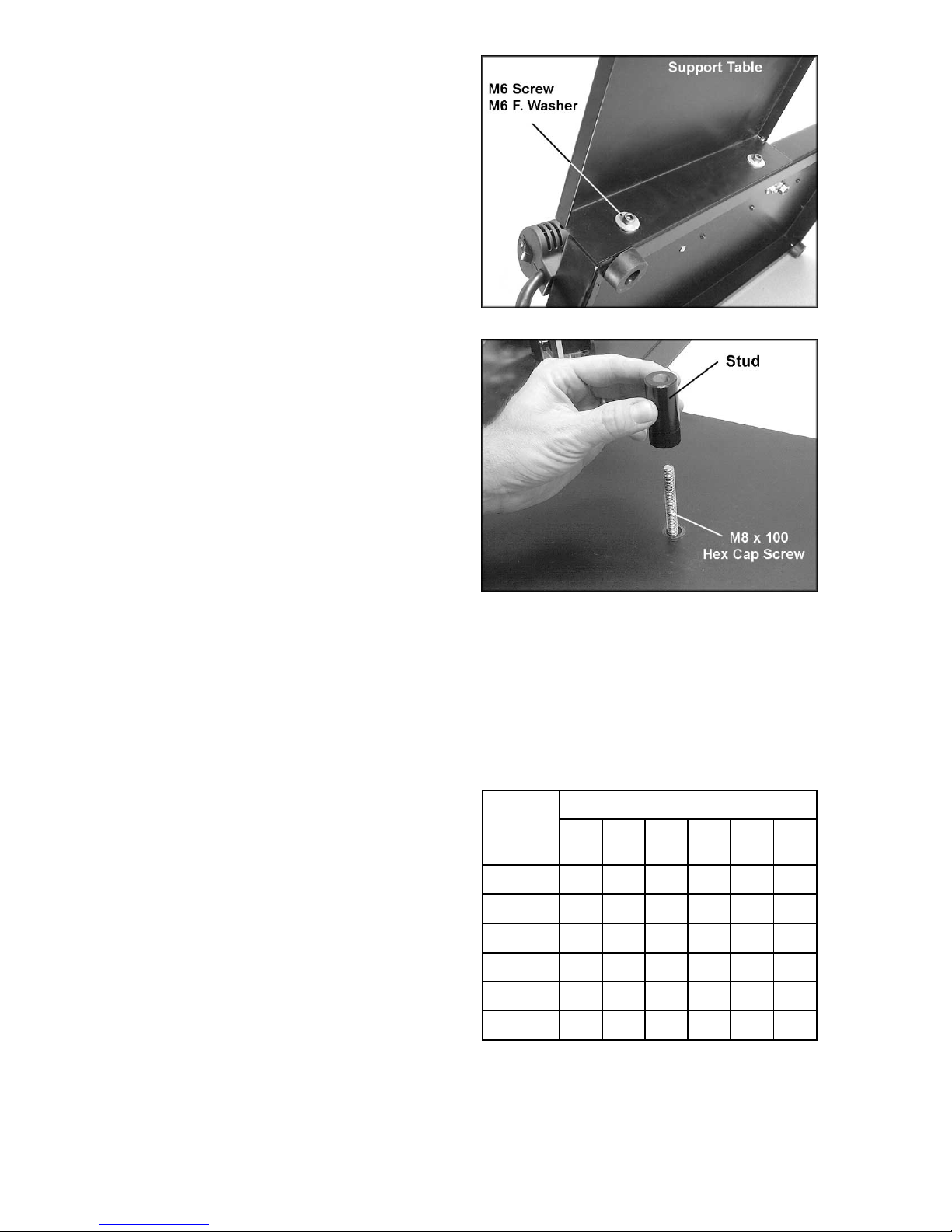
1 Support Table
1 Stud
1 Hex Cap Screw, M8 x 100 (with hex nut )
2 Socket Head Cap Screws, M6 x 10
2 Flat Washers, M6
1 Hex Wrench, 5mm
1 Double Edge Trimmer
1 Owner's Manual
1 Warranty Card
Read and understand the en t ire contents o f this manual before att empting set-up
or operation! Failure t o co mpl y may cause injury.
7
Assembly
Tools required for assembly:
5mm hex wrench (provi ded)
Installing Support Table
1. Tilt the Edge Bander up and attach the
support tabl e to the two holes at the rear of
the Edge Bander, wit h two M6 x 10 socket
head cap screws and two M6 f lat washers.
See Figure 1. Tighten with the 5mm hex
wrench.
2. Fr om below the support table, insert t he M8
x 100 hex cap screw up through the hol e in
the center of the support table as sho wn in
Figure 2. ( The hex nut on t he screw should
be below the support tabl e.)
3. Place the stud, with its threaded opening
facing down, over the hex cap screw and
thread it down ont o the hex cap screw. See
Figure 2.
4. Adjust the M8 x 100 screw until its head
contacts the surf ace of your table or bench.
This enables the scre w to act as a support
for the support t able.
Figure 1
5. Secure the positi on of the M8 x 100 screw
by tightening the hex nut up against the
bottom of the support table.
Grounding Instructions
Make sure the voltage of your power supply
matches the specif ications on the label aff ix ed to
the heat gun. The Edge Bander is de signed to
run on standard 120 volt “ househol d” c ur r ent.
Extens ion Cords
If an extension cord is necessary, make sure the
cord rating i s suitable for the am perage listed on
the machine's motor plate. An undersize cord
will cause a drop in line voltage resulting in loss
of power and overheating.
The chart in Figure 3 shows the correct size
cord to use based on cord length and motor
plate amp rating. If in doubt, use the next
heavier gauge. The smaller the gauge number
the heavier the cor d.
Figure 2
Reco m me n de d G au g es (AWG) of Ext e ns io n C or d s
Extension Cord Length *
25
50
75
100
150
Amps
< 5 16 16 16 14 12 12
5 to 8 16 16 14 12 10 NR
8 to 12 14 14 12 10 NR NR
12 to 15 12 12 10 10 NR NR
15 to 20 10 10 10 NR NR NR
21 to 30 10 NR NR NR NR NR
*based on li miting th e lin e voltag e drop to 5V at 150% of th e
rated amp eres.
NR: Not Recommended.
feet
feet
feet
feet
feet
200
feet
Figure 3
8

Adjustments
Upper and Lower Guides
The upper and lower gui des can be adj usted by
loosening the socket head cap screws with a
5mm hex wrench (provi ded). S ee Figure 4. Aft er
adjustment, re-tighten the screws.
The lower guides should be set slightly below
the work table, after which no further
adjustments will be necessary for the lower
guides.
Adjust the upper gui des to suit the width of your
banding material. NOTE: The banding material
must move freely through the guides.
Infeed and Outfeed Fences
The infeed and outfeed fences are used to
support the edge of the workpi ece. Both f ences
should be positioned in relation to the pinch
roller to allow for the thickness of the edge
banding material being used. Normally, the
fences will be recessed about 1/32” to 3/64”
from the crown of t he pinch roller, as shown in
Figure 5. This setting has already been made
before the Edge Bander wa s shipped; howev er
you may wish to d ouble-check it . It should also
be checked occasionally as the Edge Bander
receives use.
If a fence requires adjustment, loosen the two
socket head cap screws (Fi gure 5) and shi ft the
fence forward or backward as needed.
NOTE: To adjust the infeed fence, you must f irst
remove the hot air gun fr om the table as follows:
Figure 4
Figure 5
The hot air gun should be
disconnect ed from power. If the hot ai r gun
has just been used in an edge banding
operation, allow it to cool sufficiently before
attempting to remove it.
1. On the undersi de of the Edge B ander , use a
Phillips screwdriver to remove the two
screws which secure the hot air gun (F igure
6).
2. Carefully remove the hot air gun from the
table. The socket head cap screws on the
infeed fence will now be accessible; adjust
the infeed fence as needed.
3. When finished, re-i nstall the hot air gun. Reinstall and tighten the two screws (Figure 6).
Figure 6
9
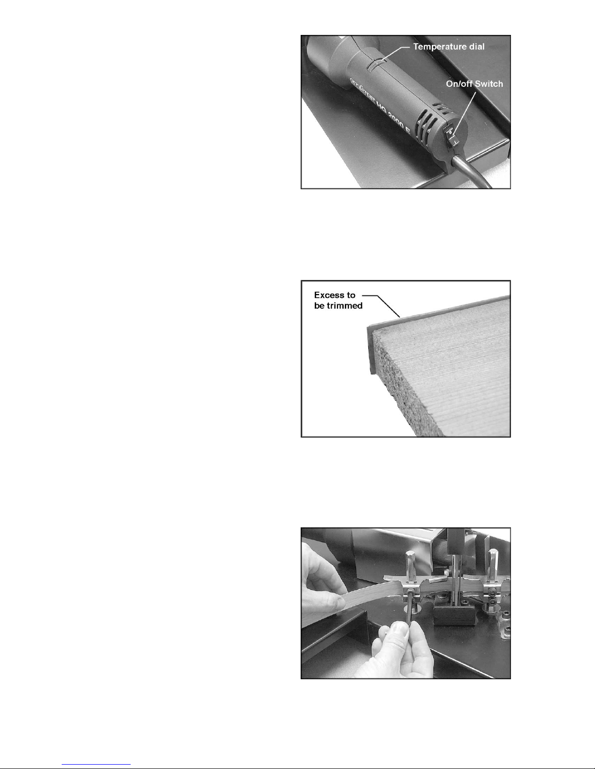
Operating Controls
The main on-off switch is on the handle of the
hot air gun (Figure 7) .
The temper ature of t he heat is cont rolled by t he
dial (Fi gure 7); hotter toward the red part of the
dial, cooler toward the blue part of the dial.
NOTE: The heat sett ing is arbitrary. The hotter
the gun, the f aster you must f eed the work. For
best results, start with a low heat and make
adjustments according to your experience with
the edge bander and the material you are using.
Operation
Figure 7
Selection of Banding Material
The edge banding m aterial must hav e a hot melt
adhesive backing.
The width of the edge banding material you
select is dependent upon the thickness of the
stock you are banding. The Edge Bander will
accept banding material up to 2-1/4” wide.
The banding material is usually no more than
1/16” wider than t he thick ness of the workpiece.
This means there i s only about 1/32” of ex cess
to remove from eit her si de of t he workpiece. See
Figure 8. This al lows the excess to be remov ed
with a knife (not provided) or the double edge
trimmer. The excess may also be removed by
sanding.
When the edge banding materi al is too wide, the
clean-up job becomes difficult and edge banding
materia l is w a sted.
Basic Procedure
1. Set the r oll of edge banding materi al on the
support table. The banding material should
be oriented so the adhesiv e backed side will
face the heat gun as it moves through the
guides.
Figure 8
(banding shown is 13/16” wide oak veneer)
2. Make sure the lower guide s have been set
slightly below the work tabl e. This will place
the bottom edge of the banding material
slightly below the edge of the workpiece.
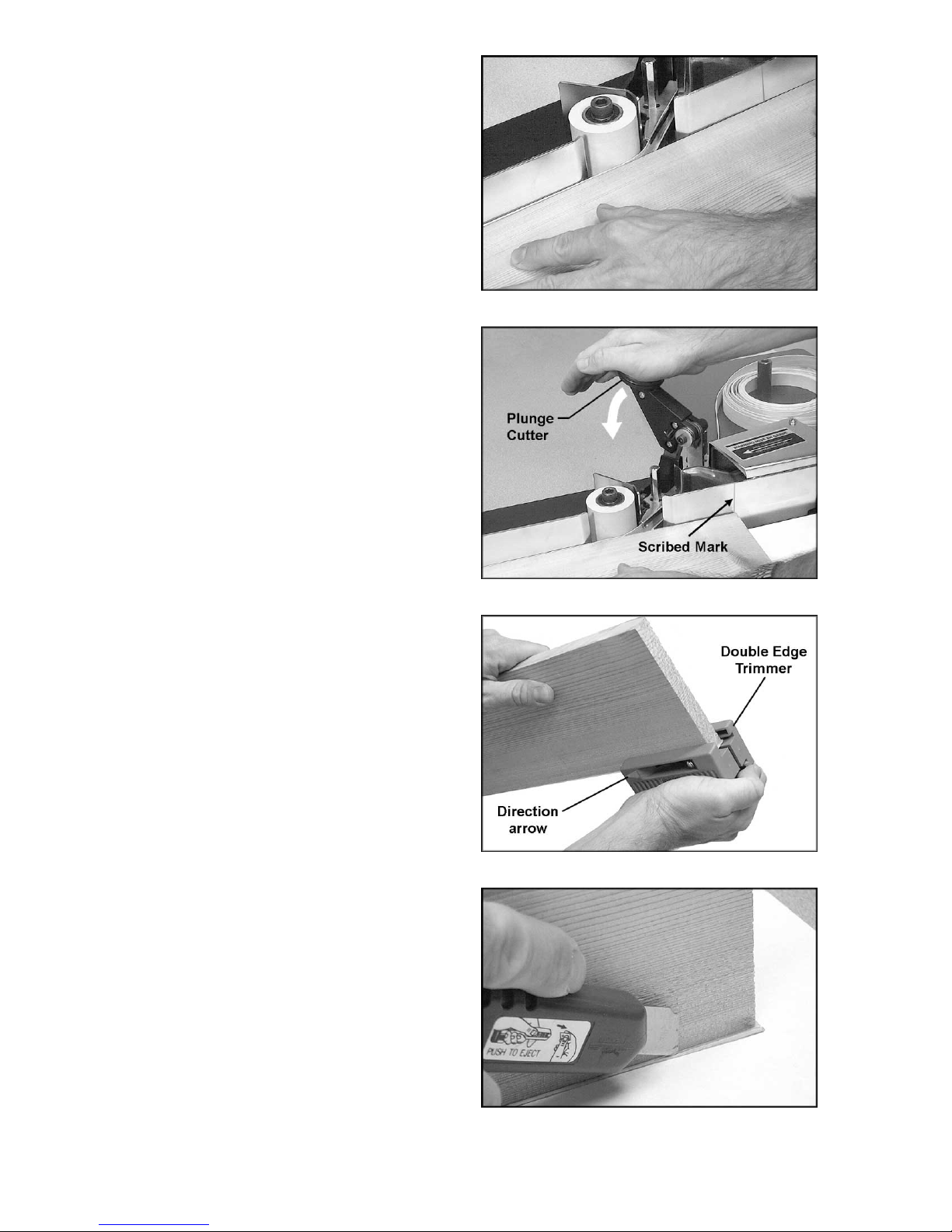
3. Slide the leading end of the banding
material t hrough the guides, and adjust the
upper guides to the width of the banding
material. See Fi gure 9. NOTE: The banding
material must move freely through the
guides.
Figure 9
10

4. Position the leading end of the banding
material i n front of the nozz le of the hot air
gun, as shown in Figure 10.
5. Choose the desired heat setting on the
temperature dial.
6. Plug the Edge Bander into the power source
and turn on the s witch. Allow approxim ately
30 seconds for the hot air gun to reach
operating temperature. Adjust the
temperature dial again if necessary.
The hot air gun generates
sufficient heat to burn flesh and ignite
combustibles. Work with extreme caution.
Do not touch metal areas around hot air gun
while it is t ur ne d on.
7. As the hot melt adhesive soft ens at t he front
end of the bandi ng material, hand feed the
banding material up to the crown of the
pinch roll er, as shown in Fi gur e 11.
NOTE: A general indi cat or that the adhesiv e
is hot enough is when it begins to bubble
slightly.
8. Place the workpiece on the table and
against the infeed fence. See Figure 12.
9. Push the edge of the workpiece along the
infeed fence and agai nst the edge banding
material (Figure 12). The edge banding
material will be trapped between the pinch
roller and the workpiece. The edge bandi ng
material will bond to the workpiece.
Figure 10
Figure 11
10. Guide the workpiece along the pinch roller
at a steady, moderate speed. The edge
banding mat erial will conti nue to bond t o the
edge of the workpiece and will be pulled
through the guides by t he movement of the
workpiece.
NOTE: Be sure the hot melt adhesive is
bonding to the workpiece. If you feed the
workpiece too fast, or the hot air gun
temperature is set too l ow, the bond will be
poor. Make adjustments as needed to
obtain a good bond.
Figure 12
11
11. As the workpiece is advanced (Figure 13),
the leading edge of the workpiece may be
rested against t he outfeed fence as well as
the pinch roll er. Always main tain pressure
on the pinch roller while you are edge
banding.
12. W hen the trailing end of the workpiece li nes
up with the scribed mark on the infeed
fence, push do wn on the plunge cutter firmly
and rapidly to sever the edge banding
material. See Figure 14.
13. Continue to push the workpiece forward
until the entire edge of the workpiece has
been banded. The end of the banding
material will extend slightly beyond the
trailing end of the workpiece.
14. Shut of f the hot air gun and al low it to cool
completely before storing the Edge Bander.
When the Edge Bander is not being used,
unplug it from t he power source.
Figure 13
15. Trim the excess banding material from the
workpiece. Thi s can be done ea sily wit h the
Double Edge Trimmer provided with your
Edge Bander. See Fi gur e 15.
16. The Double Edge Trimmer will work on
materials 1/2” to 1” thick. Simply place the
Trimmer over the banded edge of the
workpiece and squeeze the Trimmer firmly
to clamp it against the workpiece edge.
Continue to squeeze i t firmly, and slide the
Trimmer down the edge of the workpiece i n
the direction of the arrows, as shown in
Figure 15. Use steady, even pressure for
best results.
17. Replacement knives (Stock No. JEB-151)
are available f or the Double Edge Trimmer.
To order, contact your local distributor or
call customer service at 1-800-274-6848.
Figure 14
Figure 15
18. A sharp knife (not provided), as shown in
Figure 16, is an alternative method for
trimming the excess banding material. The
excess may also be sanded off in some
cases.
Figure 16
12
Maintenance
Before doing maintenance
on the Edge Bander, unplug it from the
power source, unless sp ecified otherwise.
Prolonged use of the Edge Bander may cause
accumulation of hot melt adhesive on the
guides, which can block free movement of the
edge banding material. To remove this
adhesive, pl ug in t he tool and tur n it on, with t he
heat gun at a medium setting. Keep hands
away from hot air gun. As the heat gun softens
the hot melt adhesive, peel the adhesive from
the guides with a putty knife. Be careful not to
scratch the gui des; they m ust remain sm ooth for
best results.
If the pinch roller needs cleaning, wipe it with
soap and water. Do not use solvents on the
pinch roll er.
If the power cord is worn, cut, or damaged in
any way, have it repl ac ed immediately.
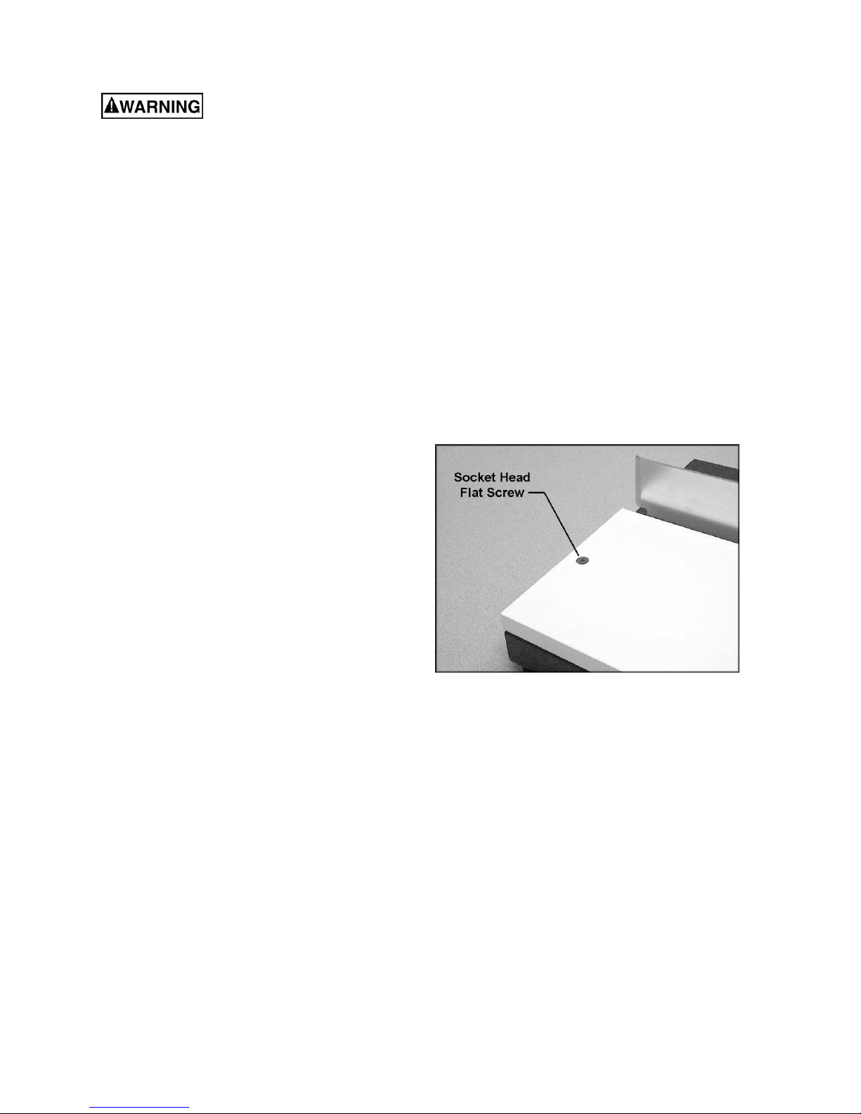
Main Table Replacement
The laminated front table may eventually
become scuffed with use. It can be replaced
with any smooth faced stock. Remove the old
table by unscrewing and removing the two
socket head flat screws, shown in Figure 16,
with a 5/32” (or 4mm) hex wrench (not
provided). Use the old table as a pattern for
cutting the new one.
A plastic lami nate f ace may be gl ued t o the new
table. This will i ncrease its durabili ty and reduce
friction bet ween the tabl e and the workpiec e. Be
sure the new table i s the same t hickness as the
original. Make an allowance for the plastic
laminate if y ou plan to laminate your new work
table.
Figure 16
13

Troubleshooting the JEB-1 Edge Bander
Trouble Probable Cause Remedy
Edge Bander will not
turn on.
Edge Bander will not
heat.
Edge banding
material does not
feed smoothly
through guides.
Edge banding
material will not bond
to workpiece.
Not connected to power source. Check plug connection.
Fuse blown, or cir c uit break er tr ipped. Replace fuse, or reset circuit break er .
Cord damaged. Replace cord.
Hot air gun motor damaged. Have hot air gun repai r ed or replaced.
Temperature dial not set properly. Turn temperature dial toward the red.
Hot air gun motor damaged. Have hot air gun repai r ed or replaced.
Guides not adjust ed pr oper ly.
Guides need cleaning.
Hot air gun not hot enough.
Feed rate too fast for heat level.
Infeed and/or outfeed fence not set
properly.
Position guides accor ding to width of
edge banding mat erial. [page 9]
Follow instructions for cleaning off old
adhesive from guides. [page 13]
Turn temperature dial toward the red
to increase heat.
Reduce feed rate, or increase heat
level.
Fences should be recessed 1/32” t o
3/64” from crown of pi nc h roll er .
[page 9]
Edge banding
materia l is di ffi cult to
cut.
Edge banding materi al does not have
hot melt backing, or has poor
adhesive or is defective.
Plunge cutter being pushed down too
lightly or slowly.
Knives in plunge cutter unit are dull. Replace kniv es in plunge cutter unit.
Replace edge banding material.
Push down plunge cutter r apidly and
firmly.
14

Replacement Parts
Replacement part s are li sted on the f ollowing page s. To order par ts or reac h our servi ce depar tment, call
1-800-274-6848 between 7:00 a.m. and 6:00 p.m. (CST), Monday through Friday. Having the Model
Number and Serial Number of your machine available when you cal l will allow us to serv e y ou quickly and
accurately.
JEB-151.......Knives for Double Edge Trimmer (set of 4)
15

Parts List: JEB-1 Edge Bander
Index No. Part No. Description Size Qty
1...............JEB-101.................. Support Table.................................................... ...................................1
2...............JEB-102.................. Stud................................................................... ...................................1
3...............TS-1503021............Socket Head Cap Screw.................................... M6 × 10....................16
4...............JEB-104.................. Flat Washer....................................................... M6 × 20......................7
5...............JEB-105.................. Upper Edge Guide............................................. ...................................2
6...............JEB-106.................. Roller................................................................. ...................................1
7...............BB-6200ZZ.............. Ball Bearing....................................................... #6200ZZ.....................2
8...............TS-1505131............Socket Head Cap Screw.................................... M10 × 80....................1
9...............TS-1533052............Phillips Pan Head Machine Screw...................... M5 × 16......................3
10.............JEB-110.................. Handle (Right) ................................................... ...................................1
11.............JEB-111.................. Handle (Left) ...................................................... ...................................1
12.............TS-1541021............ Nylon Lock Hex Nut........................................... M6..............................2
13.............JEB-113.................. Retaining Clamp Screw......................................M5 × 60......................2
14.............TS-1550031............ Flat Washer....................................................... M5..............................2
15.............JEB-115.................. Heat Shield........................................................ ...................................1
16.............JEB-116.................. Top Retaining Clamp......................................... ...................................1
17.............JEB-117.................. Bottom Retaining Clamp.................................... ...................................1
18.............JEB-118.................. Nozzle............................................................... 070236 .......................1
19.............JEB-119.................. Hot Air Gun........................................................ ...................................1
20.............JEB-120.................. Electric Cord...................................................... ...................................1
21.............TS-1514031............ Socket Head Flat Screw.....................................M6 × 20......................2
22.............JEB-122.................. Work Tab le........................................................ ...................................1
23.............JEB-123.................. Rubber Foot ...................................................... ...................................4
24.............TS-1482031............ Hex Cap Screw..................................................M6 × 16......................4
25.............JEB-125.................. Base.................................................................. ...................................1
26.............JEB-126.................. Fence................................................................ ...................................2
27.............TS-1533052............ Phillips Pan Head Machine Screw...................... M5 × 16......................2
28.............TS-1550061............ Flat Washer....................................................... M8..............................4
29.............TS-1540061............ Hex Nut.............................................................M8..............................2
30.............TS-1540071............ Hex Nut.............................................................M10............................2
31.............TS-1550041............ Flat Washer....................................................... M6..............................1
32.............TS-1503031............ Socket Head Cap Screw .................................... M6 × 12......................1
33.............JEB-133.................. Heat Shield........................................................ ...................................1
34.............TS-1550041............ Flat Washer....................................................... M6..............................7
35.............JEB-135.................. Stud................................................................... ...................................2
36.............JEB-136.................. Lower Edge Guide............................................. ...................................2
37.............JEB-137.................. Hex Cap Screw (Full Thread)............................. M8 × 100....................1
38.............TS-1540061............ Hex Nut.............................................................M8..............................1
39.............TS-1503041............ Socket Head Cap Screw .................................... M6 × 16......................1
40.............TS-1540031............ Hex Nut.............................................................M5..............................3
41.............JEB-141.................. Spacer............................................................... ...................................1
42.............JEB-142.................. Knife Gua r d (R ig h t)............................................ ...................................1
43.............JEB-143.................. Knife Ba se......................................................... ...................................1
44.............TS-1503081............ Socket Head Cap Screw .................................... M6 × 35......................1
45.............JEB-145.................. Spring................................................................ ...................................1
46.............JEB-146.................. Upper Knife ....................................................... ...................................1
47.............JEB-147.................. Knife Gua r d (Left) .............................................. ...................................1
48.............JEB-148.................. Botto m Kn i fe...................................................... ...................................1
49.............JEB-149.................. Clamp Ring........................................................ ...................................1
50.............JEB-150.................. Double Edge Trimmer (not shown)..................... ...................................1
51.............JEB-151.................. Knives for Double Edge Trimmer, set of 4 (not shown)........................... 1
16

JEB-1 Edge Bander
17

NOTES
18

NOTES
19

WMH Tool Gr ou p
2420 Vantage Drive
Elgin, Illinois 60123
Phone: 800-274-6848
www.wmhtoolgroup.com
20
 Loading...