

Page 1
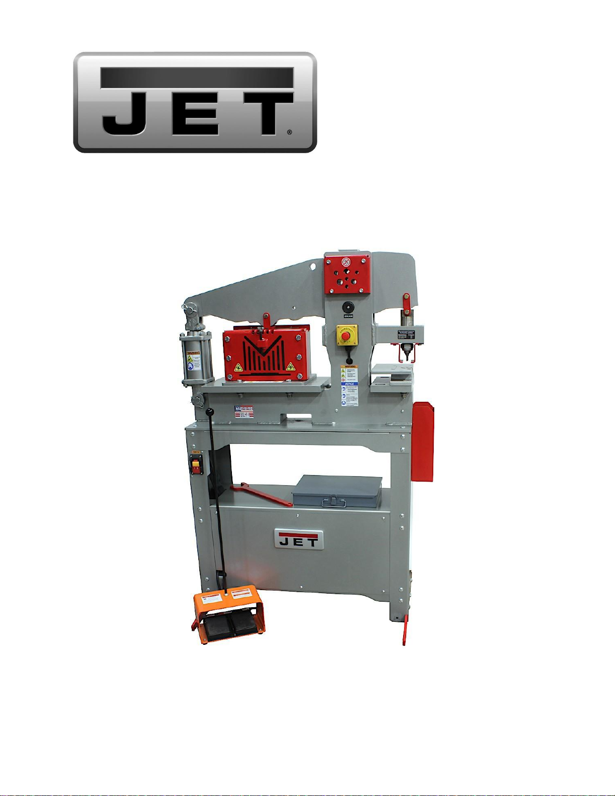
Operating Instructions and Parts Manual
45 Ton Iron Worker
Model JIW-45T
JET
427 New Sanford Road
LaVergne, Tennessee 37086 Part No. M-756100
Ph.: 800-274-6848 Edition 2 04/2022
www.jettools.com Copyright © 2022 JET
Page 2

2
1.0 IMPORTANT SAFETY INSTRUCTIONS
WARNING – To reduce risk of injury:
1.
Read and understand the entire owner's
manual before attempting assembly or
operation.
2.
Read and understand the warnings posted on
the machine and in this manual. Failure to
comply with all of these warnings may cause
serious injury.
3.
Replace the warning labels if they become
obscured or removed.
4.
This iron worker is designed and intended for
use by properly trained and experienced
personnel only. If you are not familiar with the
proper and safe operation of an iron worker,
do not use until proper training and
knowledge have been obtained.
5.
Do not use this iron worker for other than its
intended use. If used for other purposes, JET
disclaims any real or implied warranty and
holds itself harmless from any injury that may
result from that use.
6.
Always wear ANSI approved safety
glasses/face shields while using this iron
worker. Everyday eyeglasses only have
impact resistant lenses; they are not safety
glasses.
7.
Do not wear loose clothing, gloves, neckties,
rings, bracelets, or other jewelry which may
get caught in moving parts. Wear protective
hair covering to contain long hair. Non-slip
footwear or anti-skid floor strips are
recommended.
8.
Do not operate this machine while tired or
under the influence of drugs, alcohol or any
medication.
9.
Do not exceed the rated capacity of this iron
worker; use hand tools for small or narrow
parts. Do not attempt to cut hardened
materials.
10.
Sheet metal stock has sharp edges. To
prevent cuts, use leather work gloves when
handling.
11.
Keep hands and fingers clear of the moving
areas of the iron worker.
12.
Do not place your hands between material
being machined and the worktable.
13.
Keep safety guards in place at all times when
the machine is in use. If removed for
maintenance purposes, use extreme caution
and replace the guards immediately after
maintenance is complete.
14.
Check damaged parts. Before further use of
the machine, a guard or other part that is
damaged should be carefully checked to
determine that it will operate properly and
perform its intended function. Check for
alignment of moving parts, binding of moving
parts, breakage of parts, mounting and any
other conditions that may affect its operation.
A guard or other part that is damaged should
be properly repaired or replaced.
15.
Provide for adequate space surrounding
work area and non-glare, overhead lighting.
16.
Keep the floor around the machine clean and
free of scrap material, oil and grease.
17.
Keep visitors a safe distance from the work
area. Keep children away.
18.
Make your workshop child proof with
padlocks, master switches or by removing
starter keys.
19.
Give your work undivided attention. Looking
around, carrying on a conversation and
“horse-play” are careless acts that can result
in serious injury.
20.
Stand while operating this equipment. Do
not stand directly in front of the workpiece.
Maintain a balanced stance at all times so
that you do not fall or lean against moving
parts. Do not overreach or use excessive
force to perform any machine operation.
21.
Use the right tool at the correct speed and
feed rate. Do not force a tool or attachment to
do a job for which it was not designed. The
right tool will do the job better and more
safely.
22.
Use recommended accessories; improper
accessories may be hazardous.
23.
Maintain tools with care. Keep tools sharp
and clean for the best and safest
performance. Follow instructions for
lubricating and changing accessories.
24.
Do not stand on the machine. Serious injury
could occur if the machine tips over.
25.
Unplug or lock out power to the machine
when not in use.
Page 3
3
26.
Wear ear protectors (plugs or muffs) during
extended periods of operation.
27.
Make certain the switch is in the OFF position
before connecting the machine to the power
supply.
28.
Make certain the machine is properly
grounded.
29.
Make all machine adjustments or
maintenance with the machine unplugged
from the power source.
30.
Remove adjusting keys and wrenches. Form
a habit of checking to see that keys and
adjusting wrenches are removed from the
machine before turning it on.
31.
Turn off the machine before cleaning. Use a
brush or compressed air to remove chips or
debris — do not use your hands.
32.
Never leave the machine running
unattended. Turn the power off and do not
leave the machine until it comes to a
complete stop.
33.
Remove loose items and unnecessary work
pieces from the area before starting the
machine.
34.
Don’t use in dangerous environment. Don’t
use power tools in damp or wet location or
expose them to rain. Keep work area well
lighted.
Familiarize yourself with the following safety notices used in this manual:
machine damage.
injury.
This means that if precautions are not heeded, it may result in minor injury and/or possible
This means that if precautions are not heeded, it may result in serious, or possibly even fatal,
SAVE THESE INSTRUCTIONS
WARNING: This product can expose you to
chemicals including lead which is known to the
State of California to cause cancer and birth
defects or other reproductive harm. For more
information go to http://www.
p65warnings.ca.
gov.
WARNING:
Some dust, fumes and gases
created by power sanding, sawing, grinding,
drilling, welding and other construction activities
contain chemicals known to the State of
California to cause cancer and birth defects or
other reproductive harm. Some examples of
these chemicals are:
lead from lead-based paint
crystalline silica from bricks, cement and other
masonry products
arsenic and chromium from chemically treated
lumber
Your risk of exposure varies, depending on how
often you do this type of work. To reduce your
exposure to these chemicals, work in a wellventilated area and work with approved safety
equipment, such as dust masks that are
specifically designed to filter out microscopic
particles. For more information go to
http://www.p65warnings.ca.
gov/ and http://
www.p65warnings.ca.gov/ wood.
Page 4

4
2.0 Table of contents
1.0 IMPORTANT SAFETY INSTRUCTIONS .................................................................................................................................... 2
2.0 Table of contents ...................................................................................................................................................................... 4
3.0 About this manual ..................................................................................................................................................................... 5
4.0 Features .................................................................................................................................................................................... 6
4.1 Feature descriptions ......................................................................................................................................................... 7
5.0 Specifications ............................................................................................................................................................................ 8
6.0 Setup and assembly ................................................................................................................................................................ 10
6.1 Shipping contents ........................................................................................................................................................... 10
6.2 Unpacking and cleanup .................................................................................................................................................. 10
6.3 Anchoring the Machine ................................................................................................................................................... 10
7.0 Electrical connections ..................................................................................................................................................... 10
7.1 GROUNDING INSTRUCTIONS ..................................................................................................................................... 11
7.2 Extension cords .............................................................................................................................................................. 11
8.0 Setup and Adjustments ................................................................................................................................................... 12
8.1 Punch and Die changes .................................................................................................................................................. 12
8.2 Center station change ..................................................................................................................................................... 13
9.0 Operations .............................................................................................................................................................................. 14
9.1 Controls .......................................................................................................................................................................... 14
9.2 Bar and Angle Shearing .................................................................................................................................................. 14
Shearing Safe Operation ............................................................................................................................................................ 14
9.2.1 Bar Shear Operation ....................................................................................................................................................... 15
9.2.2 Angle Shear Operation ................................................................................................................................................... 15
9.3 Punch Operation ............................................................................................................................................................. 16
Punching Safe Operation ............................................................................................................................................................ 16
9.3.1 Punch Operation ............................................................................................................................................................. 16
9.3.2 Punch and Die Operating Clearances ............................................................................................................................ 17
9.3.3 Punch Tonnage Requirement ......................................................................................................................................... 18
9.4 Rod Shear Operation ...................................................................................................................................................... 19
Safe Operation ........................................................................................................................................................................... 19
9.4.1 Rod Shear Operation ...................................................................................................................................................... 19
10.0 User-maintenance .......................................................................................................................................................... 20
10.1 Blade Inspection ............................................................................................................................................................. 20
10.2 Hydraulic Oil ................................................................................................................................................................... 20
10.3 Oil Disposal .................................................................................................................................................................... 20
11.0 Troubleshooting ..................................................................................................................................................................... 21
12.0 Optional accessories ............................................................................................................................................................. 23
13.0 Replacement Parts ............................................................................................................................................................... 23
13.1 45T Iron Worker – Exploded View .................................................................................................................................. 24
13.2 45T Iron Worker – Parts List ........................................................................................................................................... 25
13.2.1 Base Assembly – Exploded View ................................................................................................................................... 26
13.2.2 Base Assembly – Parts List ................................................................................................................................ ............ 26
13.2.3 Shear Station – Exploded View ...................................................................................................................................... 27
13.2.4 Shear Station – Parts List ............................................................................................................................................... 27
13.2.5 Punch Station (Standard and Optional) – Exploded View ............................................................................................... 28
13.2.6 Punch Station (Standard and Optional) – Parts List ........................................................................................................ 28
13.2.7 Gauging Table Kit (Optional) – Exploded View ............................................................................................................... 29
13.2.8 Gauging Table Kit (Optional) – Parts List ........................................................................................................................ 29
13.2.9 Material Stop (Optional) – Exploded View ...................................................................................................................... 30
13.2.10 Material Stop (Optional) – Parts List .............................................................................................................................. 30
14.0 Warranty and service ...................................................................................................................................................... 31
Page 5

5
3.0 About this manual
This manual is provided by JET, covering the safe operation and maintenance procedures for a JET Model JIW45T Iron Worker. This manual contains instructions on installation, safety precautions, general operating
procedures, maintenance instructions and parts breakdown. Your machine has been designed and constructed
to provide consistent, long-term operation if used in accordance with the instructions as set forth in this document.
This manual is not intended to be an exhaustive guide to iron worker operational methods, usage or after-market
accessories, choice of stock, etc. Additional knowledge can be obtained from experienced users or trade articles.
Whatever accepted methods are used, always make personal safety a priority.
If there are questions or comments, please contact your local supplier or JET. JET can also be reached at our
web site: www.jettools.com.
Retain this manual for future reference. If the machine transfers ownership, the manual should accompany it.
Read and understand the entire contents of this manual before attempting assembly or
operation! Failure to comply may cause serious injury!
Register your product online –
http://www.jettools.com/us/en/service-and-support/warranty/registration/
Page 6

6
4.0 Features
Figure 1
Page 7
7
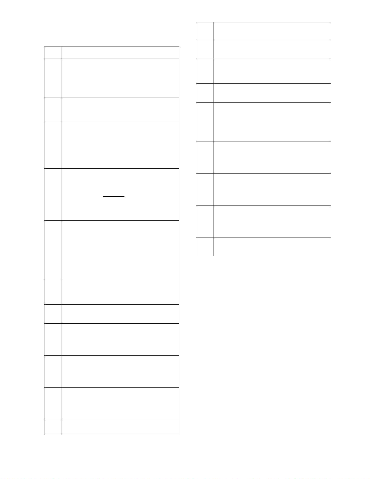
4.1 Feature descriptions
Item
Definition
A
Power Switch. When the yellow safety key
is inserted into the red switch paddle, the
paddle is lifted to start and run the hydraulic
unit. Press the paddle in to stop the
hydraulic unit.
B
Hydraulic Cylinder. The cylinder provides
the force used to punch or shear the work
material.
C
Flat/Angle Shear Station. (AKA Center
Station) This is a two-station shear which is
used to shear flat bar stock or angle iron. It
may be removed to allow room for a second
punching station. (See Optional
Accessories)
D
Emergency Stop Switch. In the event of
incorrect operation or dangerous condition,
the machine can be stopped immediately by
pressing the E-STOP button. Twist the
emergency stop button clockwise (cw) to
reset. Note: Resetting the E-Stop will not
start the machine.
E
Rod Shear Station. This station has 6 round
and 1 square shear stations. Retract the
cylinder to fully open the rod shear opening.
Extending the cylinder will then shear the
material. ONLY use one opening at a time.
NEVER use two openings at a time or insert
multiple pieces of material into any one
opening.
F
Pivot Pin. The fulcrum point for the rocker
arm. Inspect and grease as indicated in the
maintenance section.
G
Punch Ram. Lowers and raised the installed
punch during operation.
H
Punch Ram Guide Block. The Punch Ram
moves through this block during operation.
Inspect and grease as indicated in the
maintenance section.
I
Punch Station. (AKA Outboard Station) This
station is used to punch holes (commonly
round) into metals. Optional shape such as
square and oblong are available.
J
Striper. These brackets stop the upward
travel of the material when the punch is
being withdrawn from the material. Thereby
freeing the punch.
K
Punch Table. The punch table holds the die
which is mated with the punch. The table
also support the material during the
punching operation.
L
Slug Receptacle. Catches the slugs from
the punching operation.
M
Punch and Die Accessory Box with tooling.
This is an optional accessory. Contact Jet
Sales for more information.
N
Punch Nut Wrench. Fits the punch nut for
installation and removal of the punch.
O
Cylinder Retract Foot Pedal. Pressing this
pedal will retract the cylinder rod to lower
the shear blade (flat and angle shearing
operation) and lift the punch for the
outboard punching operation.
P
Cylinder Extend Foot Pedal. Pressing this
pedal will extend the cylinder rod to lift the
shear blade and lower the punch for the
outboard punching operation.
Q
Hydraulic Unit Housing. Housing the
hydraulic power unit which consists of the
motor, pump, reservoir, and directional
valving.
R
Punch And Die Holder. Punch and Die sets
used frequently may be stored in this holder
for easy access. Punch and Die sets sold
separately.
S
Gib Adjusters. These adjusters ride against
the rocker arm for alignment.
Page 8
8
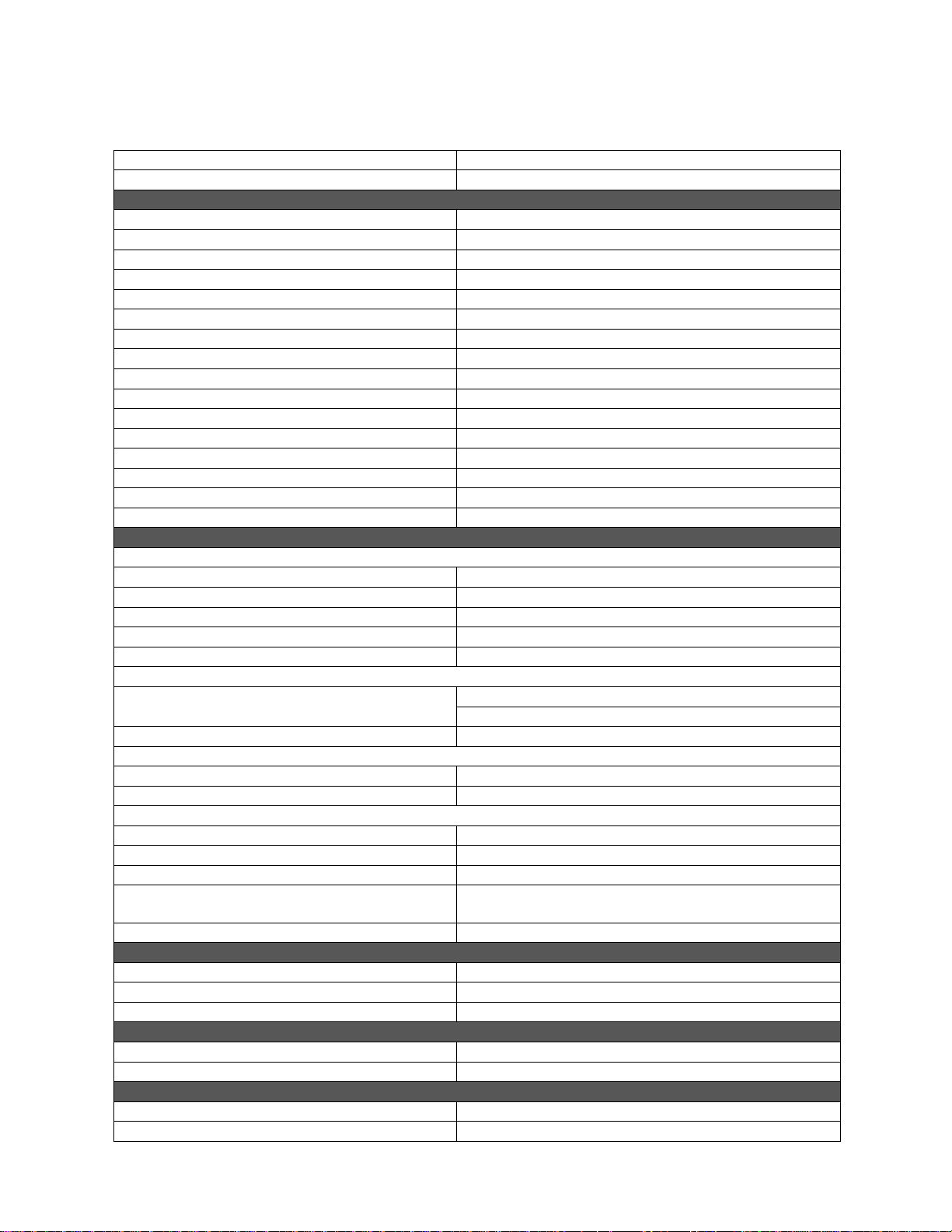
5.0 Specifications
Table 1
Model number
JIW-45T
Stock numbers
756100
Motor and Electrical
Power Supply
115VAC, 1ph, 60hz
Motor type
totally enclosed fan cooled
Horsepower
1.5HP (1.1kW)
Phase
Single
Voltage
120V
Cycle
60Hz
Listed FLA (full load amps)
14A
Motor speed
3500 RPM
Hydraulic Pump Flow
1.0 GPM (4.54LPM)
Hydraulic Pump Pressure
2800 PSI (193)
Hydraulic Reservoir Capacity
3 – 3.2 QTS (2.8 – 3L)
Hydraulic Oil Type
ISO 46
On/off switch
Toggle w/Safety Key
Power cord
14AWG x 3C, SJT, 6 ft.
Power plug
5-15P
Recommended minimum circuit size
1
20 A
Capacities
PUNCH
Punch Station Rating (U.S. Tons)
45T
Punch Station Maximum Capacity
Ø1” x 1/2” thick mild steel (Ø25.4 x 12.7mm)
Punch Station Work Height
41” (1041.4mm)
Punch Station Throat Depth
5-3/4” (146mm)
Punch Station Stroke
1-1/2” (38.1mm)
FLAT BAR SHEAR
Flat Bar Shear Maximum Capacity
1/4" x 8” mild steel (6.35 x 203.2mm)
3/8” x 4” mild steel (9.5 x 101.6mm)
Flat Bar Shear Work Height
40” (1016mm)
ANGLE SHEAR
Angle Shear Maximum Capacity
3 x 3 x 1/4" mild steel (76.2 x 76.2 x 6.35mm)
Angle Shear Work Height
43” (1092.2mm)
ROD SHEAR
Rod Shear Stations
7 @ 6 Round and 1 Square
Rod Shear Round Maximum Capacity
3/4" (19.05mm)
Rod Shear Square Maximum Capacity
5/8” (15.875mm)
Rod Shear Round Sizes
1/4", 5/16”, 3/8”, 1/2", 5/8”, and 3/4"
(6.35, 7.93, 9.52, 12.7, 15.87, 19.05mm)
Rod Shear Work Height
55” (1397mm)
Body Construction
Frame
steel plate
Stand/cabinet
sheet metal
Paint finish
powder coat
Dimensions
Overall dimensions, assembled (LxWxH)
40 x 24 x 58 in. (1016 x 610 x 1473 mm)
Shipping dimensions (LxWxH)
51 x 45 x 64 in. (1296 x 1143 x 1626 mm)
Weights
Net weight, full assembled
698 lbs. (316.6 kgs)
Shipping weight
802 lbs. (363.8 kgs)
Page 9

9
1
Subject to local/national electrical codes. Recommendation based upon dedicated circuit.
2
The specified values are emission levels and are not necessarily to be seen as safe operating levels. As workplace
conditions vary, this information is intended to allow the user to make a better estimation of the hazards and risks
involved only.
3
Test condition: 8-in. inlet with standard canister filter installed.
L = length, W = width, H = height
n/a = not applicable
The specifications in this manual were current at time of publication, but because of our policy of continuous
improvement, JET reserves the right to change specifications at any time and without prior notice, without incurring
obligations.
Page 10
10
Read and understand the
entire contents of this manual before attempting
assembly or operation. Failure to comply may
cause serious injury.
6.0 Setup and assembly
6.1 Shipping contents
Contents
1 Angle/Flat Shear Station (installed)
1 Punch and Die Holder Station (installed)
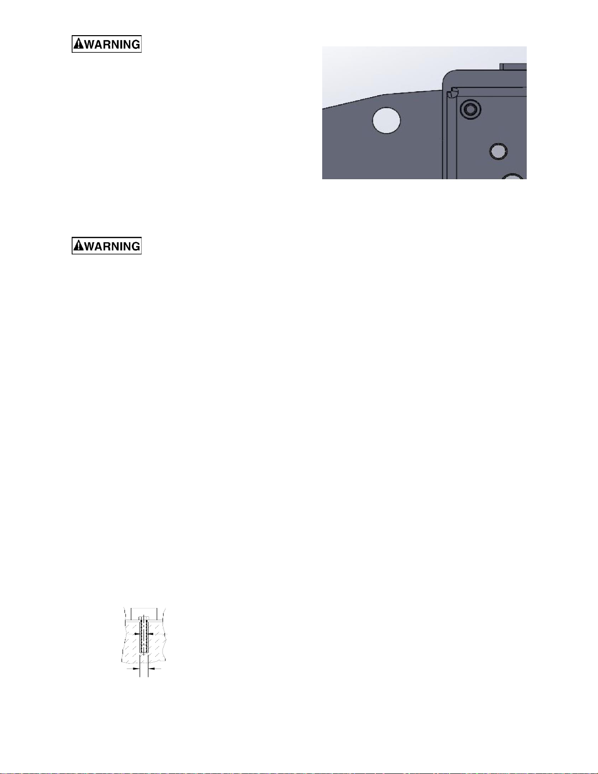
1/2” Punch and Die Set Lifting Hole in Center
1 Punch Station Slug Receptacle Lift Hole provided in picture above, lifting in any other
1 Punch Nut Wrench Location may Cause Personal Injury or Damage.
Read and understand all
assembly instructions before attempting
assembly. Failure to comply may cause serious
injury.
6.2 Unpacking and cleanup
1.
This Ironworking machinery is fully assembled
and is shipped either by palletized custom
wooden crate or by shrink–wrapped wooden
pallet for ease of transport and receiving.
2.
Inspect the packaging for damage. Report
damage, if any, to your distributor. Follow
shipping/receiving instructions as listed on the
packaging prior to receiving the Ironworker into
your facility.
3.
When receiving your Ironworker, be prepared to
safely move your machinery with a fork-lift rated
for the equipment weight.
4.
Do not discard carton or packing material until
the ironworker is installed and running
satisfactorily.
5.
Compare contents of shipping carton with the
contents list in this manual. Report shortages, if
any, to your distributor.
6.3 Anchoring the Machine
Once positioned, anchor the machine to the floor, as
shown in the diagram. Use bolts and expansion plugs
or sunken tie rods that connect through and are sized
for the holes in the base of the stand.
Checking hydraulic fluid
The hydraulic oil is the primary medium for
transmitting pressure and lubricating the running
parts of the pump.
1.
After installation of the machine and before
machine startup, bring the oil level to within
operating range.
2.
Verify that the cylinder ram is in the retracted
position to prevent overfilling of the tank.
3.
Remove the rear cabinet panel to access the
hydraulic system.
4.
Verify that the oil level is between the Min. and
Full marks.
5.
Add ISO 46 hydraulic oil if needed to bring the
oil level to the proper level.
6.
Recheck the oil level after the first few hours of
operation and again after the first full week of
operation.
A shortage of hydraulic oil can cause hydraulic
system breakdown and damage to major
mechanical parts due to overheating.
7.0 Electrical connections
The JIW-45T ironworker is rated at and wired for
115V power. The ironworker comes with a plug
designed for use on a circuit with a grounded outlet
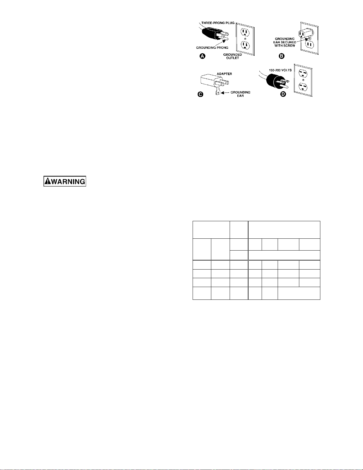
that looks like the one pictured in A, Figure 20.
Before connecting to power source, be sure switch
is in off position.
It is recommended that the ironworker be connected
to a dedicated 20 amp circuit with a 20 amp circuit
breaker or time-delay fuse.
Local codes take precedence over
recommendations.
.31"
(7.87mm)
.50"
(12.7mm)
This machine requires a solid floor such as
concrete at a minimum of 4” (102mm) thick. 6”
(153mm) minimum is preferred.
Page 11
11
7.1 GROUNDING INSTRUCTIONS
1.
All Grounded, Cord-connected Tools:
In the event of a malfunction or breakdown,
grounding provides a path of least resistance for
electric current to reduce the risk of electric shock.
This tool is equipped with an electric cord having an
equipment-grounding conductor and a grounding
plug. The plug must be plugged into a matching
outlet that is properly installed and grounded in
accordance with all local codes and ordinances.
Do not modify the plug provided - if it will not fit the
outlet, have the proper outlet installed by a qualified
electrician.
Improper connection of the equipment-grounding
conductor can result in a risk of electric shock. The
conductor with insulation having an outer surface
that is green with or without yellow stripes is the
equipment-grounding conductor. If repair or
replacement of the electric cord or plug is
necessary, do not connect the equipment-grounding
conductor to a live terminal.
Check with a qualified
electrician or service personnel if the grounding
instructions are not completely understood, or if
in doubt as to whether the tool is properly
grounded. Failure to comply may cause serious
or fatal injury.
Use only 3-wire extension cords that have 3-prong
grounding plugs and 3-pole receptacles that accept
the tool's plug.
Repair or replace damaged or worn cord
immediately.
2.
Grounded, cord-connected tools intended for use
on a supply circuit having a nominal rating less than
150 volts:
This tool is intended for use on a circuit that has an
outlet that looks like the one illustrated in A, Figure
3. An adapter, shown in B and C is not
recommended. Provide a properly grounded outlet
(A) installed by a qualified electrician. This adapter
is not permitted in Canada.
Figure 3
7.2 Extension cords
The use of extension cords is discouraged; try to
position equipment within reach of the power
source. If an extension cord becomes necessary, be
sure it is heavy enough to carry the current your
product will draw. An undersized cord will cause a
drop in line voltage resulting in loss of power and
overheating.
Position extension cords as to avoid a trip hazard.
Comply with OSHA guidelines.
Table 2 shows recommended size to use depending
on cord length and nameplate ampere rating. If in
doubt, use the next heavier gauge. The smaller the
gauge number, the heavier the cord.
Ampere
Rating
Volts
Total length of
cord in feet
More
Than
Not
More
Than
120
240
25
50
50
100
100
200
150
300
AWG
00
06
18
16
16
14
06
10 18
16
14
12
10
12 16
16
14
12
12
16 14
12
Not
Recommended
Extension Cord Recommendations
Table 2
Page 12
12
8.0 Setup and Adjustments
Disconnect ironworker from
power source before making adjustments.
8.1 Punch and Die changes
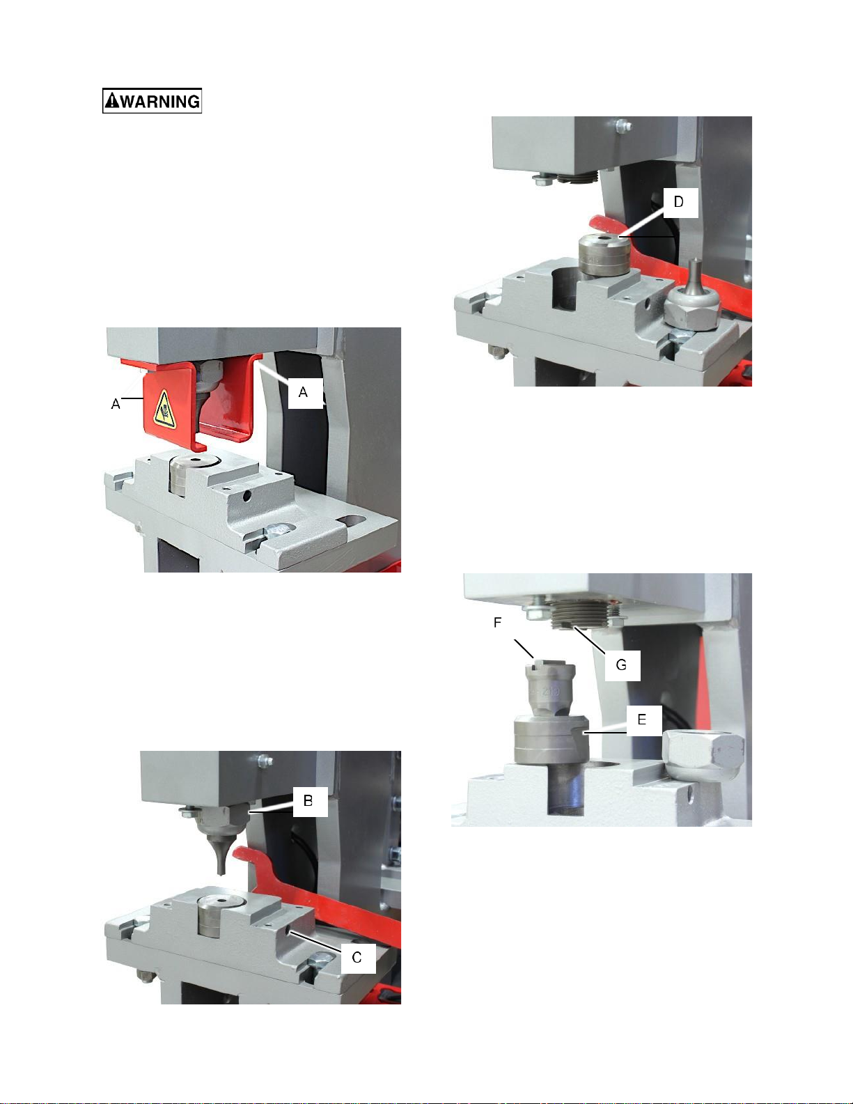
Referring to Figures 4 - 7:
1.
Run the ironworker to fully retract the cylinder
thereby lifting the punch fully open/up position.
2.
Stop the motor and disconnect the ironworker
from the power supply.
3.
Using a 1/2" wrench, loosen the hex head
screws (Fig. 4, A) that secure the strippers to
the punch block.
Figure 4
(Punch table removed to expose the die set screw.
Do not operate the punch with the table removed.)
4.
Using the punch nut wrench, loosen the punch
retaining nut (Fig. 5, B). Continue to unscrew
the nut from the punch ram and remove the
punch from the nut.
5.
Using a 3/16” hex key, loosen the set screw
(Fig. 5, C) securing the die to the table.
Figure 5
6.
Lift the die out of the table cavity and place in
storage with the mating punch.
Always keep the punch and dies together as a set
to maintain the proper punch to die clearance.
Figure 6
7.
Insert the die into the table with the flat surface
(Fig. 6, D) up and firmly tighten the set screw
(Fig. 5, C). Do not overtighten the set screw.
8.
Place the punch into the punch nut.
9.
Thread the punch nut and punch assembly onto
the punch ram. Be sure that the punch sits flat
against the ram and is not cocked within the nut.
10.
Firmly tighten the punch nut. Do notovertighten.
Figure 7
When installing directional punches such as square
or oblong punches. The direction of the punch must
match the direction of the die. Start with the die and
then install the punch.
11.
Install the die into the table with the table cavity
with the flat surface (Fig. 6, D) up and the flat
side (Fig. 7, E) toward the set screw. Lightly
snug the set screw to cause the die to rotate into
alignment.
Page 13
13
12.
Install the punch into the punch nut.
13.
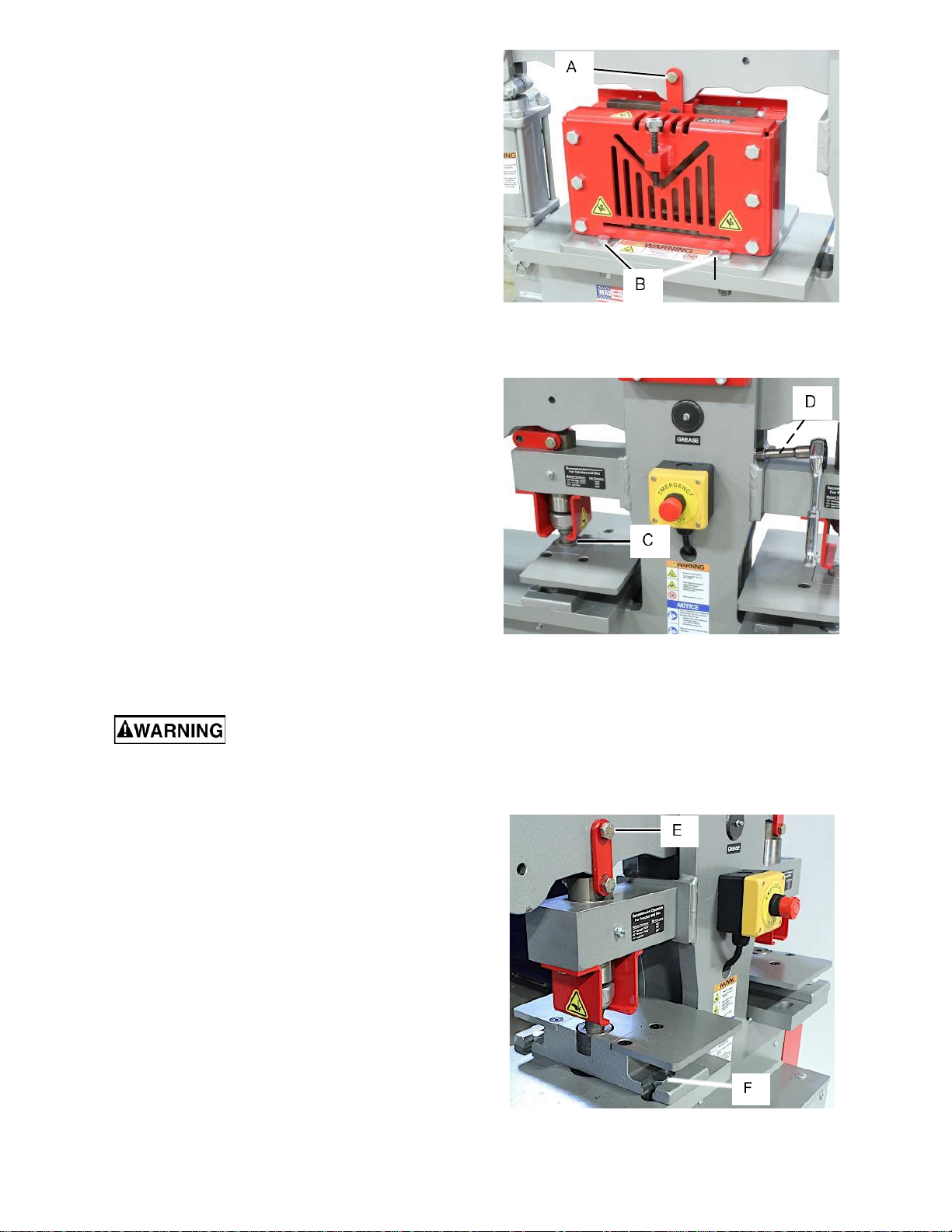
Place the square key (Fig. 7, F) into the groove
on the top of the punch and engage the punch
and key assembly into the groove on the punch
ram (Fig. 7, G).
14.
Hold the punch and key in position and secure
with the punch nut. Verify that the key has
remained in place and firmly tighten the punch
nut. Do not overtighten.
15.
Install the strippers onto the punch block and
tighten in place. (Fig. 4, A)
16.
Start hydraulics and slowly, using a press and
release of the foot pedal, lower the punch into
the die to verify the punch enters the die with
clearance around the total perimeter. DO NOT
allow the punch to contact the die in any way.
Should contact occur, verify that the correct
punch and die are matched together or that the
punch and die are aligned. Square and Oblong
set especially.
17.
Once the punch and die have been verified in
alignment and secured, the ironworker may be
returned to service.
8.2 Center station change
Referring to Figures 8 - 11:
Tools required for assembly:
5/8” open-end wrench
3/4” open-end wrench
9/16” socket wrench with extension
The center station is fitted with the flat/angle shear
station as standard. An optional punch station may
be installed in place of the shear station.
This procedure will require the
ironworker to be powered on to change the
position of the rocker arm. ALWAYS disconnect
power to the machine before performing the
steps when the rocker arm is to be stationary.
Failure to do this may result in serious personal
injury.
1.
The cylinder should be in the retracted position.
If not, power the ironworker On and press the
cylinder retract pedal to fully retract the cylinder.
2.
Disconnect the ironworker from the power
supply.
3.
Remove the blade to rock arm pivot bolt (Fig. 8,
A).
4.
Remove and retain the four bolts (Fig. 8, B)
mounting the shear station to the frame table.
5.
Power the ironworker On and press the cylinder
extend pedal to raise the rocker arm away from
the shear blade.
6.
Disconnect the ironworker from the power
supply.
Figure 8
7.
Remove and store the shear station until
needed again.
Figure 9
8.
Place the punch table and the punch block on
the frame table. Allow the punch to engage the
die and assist in alignment. It is recommended
to use the 1" punch and die set. (Fig. 9, C)
9.
Install the four hex head screws using the 9/16"
socket wrench with extension to install and
tighten the cap screws. (Fig. 9, D)
Figure 10
Page 14
14
10.
Raise the connector plates and install the
rocker arm pivot bolt. (Fig. 10, E)
11.
Install the table retaining bolts, flat washers,
heavy washers, and nuts. Center the bolts
within the slots so that the bolts form a straight
line from each bolt through the center of the die.
(Fig. 10, F).
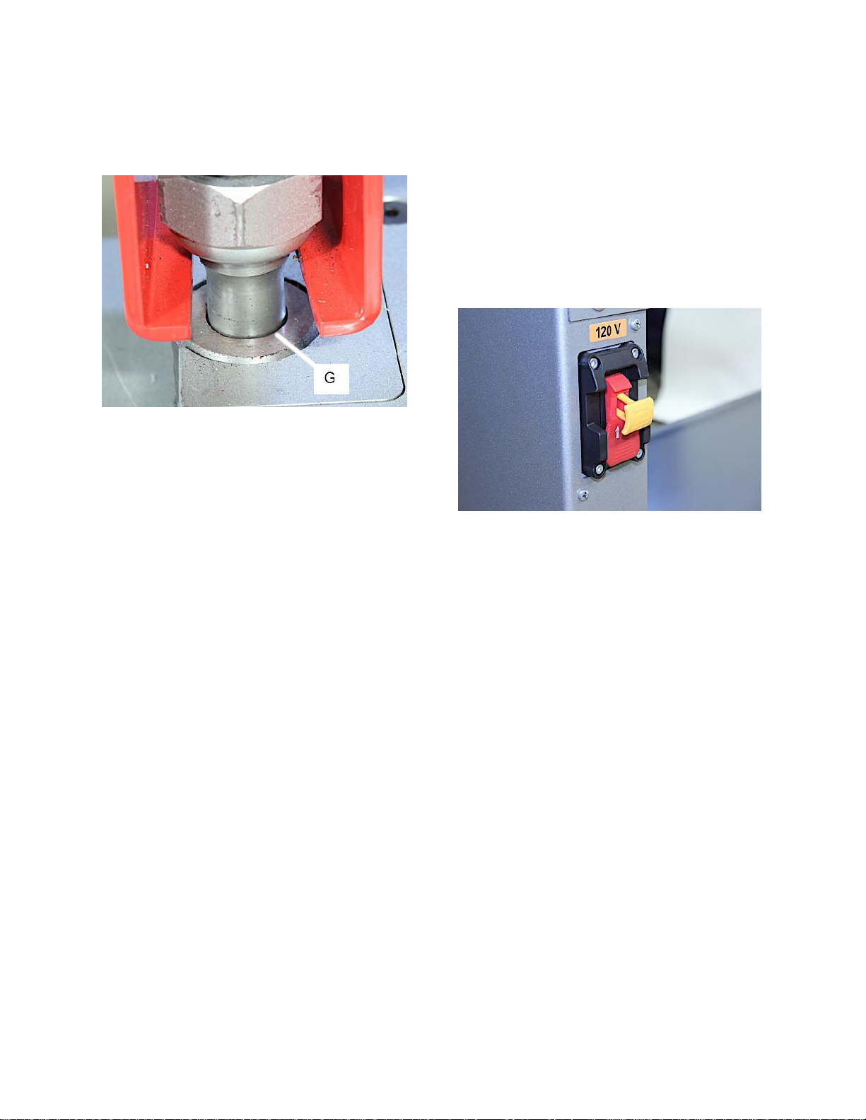
Figure 11
12.
Verify that the punch to die gap is even and
equal all the way around the punch. (Fig. 11, G)
13.
Hold the table and bolts in this position and
tighten securely. (Fig. 10, F).
14.
Start hydraulics and slowly, using a press and
release of the foot pedal, lower the punch into
the die to verify engagement. DO NOT allow the
punch to contact the die in any way. If this
happen, verify that the correct punch and die
are matched together or that the punch and die
are aligned. Square and Oblong set especially.
9.0 Operations
9.1 Controls
Start / Stop Paddle Switch:
Referring to Figure 12:
1.
Insert the yellow safety lockout key and lift up
on the paddle to start the ironworker.
2.
Push down on the paddle to stop the
i ronworker.
3.
If leaving the ironworker unattended, remove
the yellow safety lockout key to prevent
unauthorized usage. Store the lockout key in a
safe location for authorized persons only.
Figure 12
9.2 Bar and Angle Shearing
Your Ironworker includes a bar and a angle iron
shear as a standard feature. These shear stations
will provide a distortion and burr free shear cut to
mild steel stock as listed in the Ironworker
Specifications as well as described on the capacity
labels positioned at the Shearing Station.
The Bar Shear allows for straight or angled cutting
operations.
The Angle Shear allows for straight cutting
operations. A material hold down adjusts with a
simple thumb crank to safely restrain the material
being cut.
The bar and angle shears are factory tuned toproper
clearances and are ready to begin shearing
operations. [Shear blades are wearing parts and will
need to be maintained or replaced over time.
Shearing Safe Operation
Observe the following guidelines when operating the
Shear Station:
•
Never exceed the capacities of the machine or
tooling as described in the Ironworker
Specifications or listed at the tooling station.
•
Do not stack material to cut in the shear station.
Page 15
15
•
Perform complete shear operations only. Partial
shear cuts may jam the drop off side of the
frame and could result in breakage andoperator
injury.
•
Do not shear angle smaller than the hold-down
will accommodate.
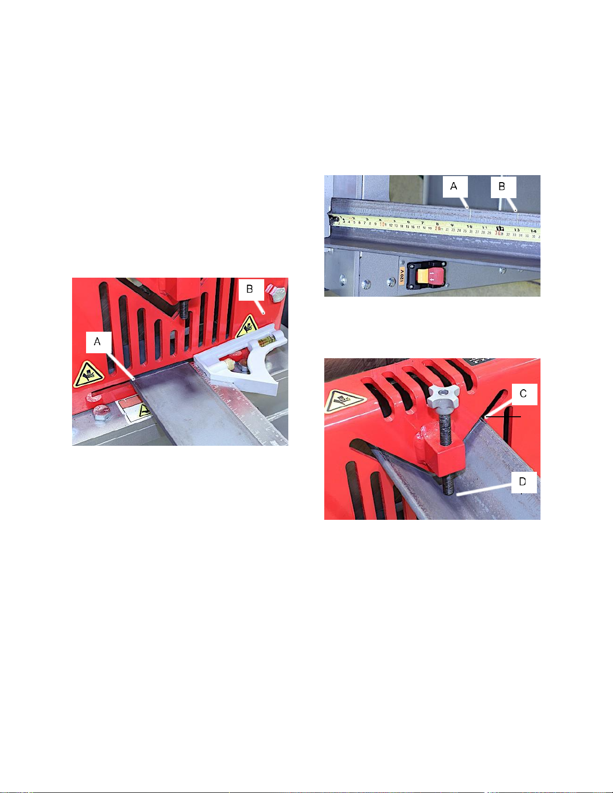
9.2.1 Bar Shear Operation
Referring to Figures 13:
1.
Clear shear station of any tools or debris prior
to powering the machine on.
2.
Turn machine on.
3.
Press the foot pedal to extend the cylinder to
raise the angle shear blade.
4.
Mark the material for the length needed.
Example: 10” length wanted. Marked at 13” for
alignment.
Figure 13
5.
Place bar stock into the material hold-down and
position your cut mark adjacent to the front
surface of the hold down. (Fig. 13, A)
6.
Use a square as needed to square the material
to be cut.
7.
Use one or two drops of SAE#30 oil at the shear
blade slides and between the blades to extend
the life of the blades.
8.
Hold the workpiece firmly, keeping your hands
a safe distance away from the working area. Do
not stand directly behind the workpiece during
the shearing operation, but off to one side.
Once safely positioned, use your foot to press
and hold the cylinder retract pedal. Maintain
pressure until the workpiece has been sheared.
9.
When the cut is complete, release the retract
foot pedal and press the extend foot pedal to
open the shear station for the next cut.
9.2.2 Angle Shear Operation
Referring to Figures 14 – 15:
1.
Clear shear station of any tools or debris prior
to powering the machine on.
2.
Turn machine on.
3.
Press the foot pedal to extend the cylinder to
raise the angle shear blade.
4.
Mark the material for the length needed.
Example: 10” length wanted (Fig. 14, A).
Marked at 13” for alignment (Fig. 14, B)
Figure 14
5.
Place angle iron into the material hold-down
and position your cut mark adjacent to the front
surface of the hold down. (Fig. 15, C)
Figure 15
6.
Hold the material perpendicular to the shear
guard and adjust the material hold-down hand
screw to lightly contact the material and prevent
the material from lifting during the actual
shearing process.
7.
Use one or two drops of SAE#30 oil at the shear
blade slides and between the blades to extend
the life of the blades.
8.
Clear your hands away from guards indicating
possible pinch points, securely hold material,
press the foot cylinder retract pedal to activate
the shear station. If material is long, use a
material stand for support.
9.
When the cut is complete, release the retract
foot pedal and press the extend foot pedal to
open the shear station for the next cut.
Page 16

16
9.3 Punch Operation
Your Ironworker is capable of punching materials as
listed in the Ironworker Specifications as well as
described on the capacity labels positioned adjacent
to the Punch station.
Punching Safe Operation
Please observe the following guidelines when
operating the Punch Station:
•
Follow manufacturers punch and die clearance
recommendations. Follow punch tonnage
requirements.
•
Never exceed the capacities of the machine or
tooling as described in the Ironworker
specifications or listed at the tooling station.
•
The thickness of the material you are punching
should not exceed the diameter of the punch
being used.
•
Check punch and die alignment after every
tooling change or extended punch operation.
•
Do not stack material to punch in the punching
station.
•
Punch complete holes only – partial holes will
side load the punch tooling and could result in
punch breakage and operator injury.
•
Use punching aids when working with small
items at the punch station.
9.3.1 Punch Operation
1.
Clear the punch station of any tools or debris
prior to powering the machine on.
2.
Layout the location for the hole to be punched.
Center punching the location will assist in
alignment.
3.
Place the material to be punched between the
punch and die, centering the hole location under
the punch point. Check to see that the stripper
will contact the material evenly during punch
retraction.
4.
Use one or two drops of SAE#30 oil at the
punch to aid in stripping material from the punch
as well as to extend the life of the punch tooling.
5.
Clear your hands away from guards indicating
possible pinch points, securely hold material,
press the foot cylinder pedal to move the punch
through the material and into the die. If material
is long, use a material stand for support.
6.
When the cut is complete, release the extend
foot pedal and press the retract foot pedal to
open the punch station for the next cut.
Note: When using the optional center
punch station, the foot pedal operation will
be reversed.
Secondary Punch Station #756105
Page 17
17
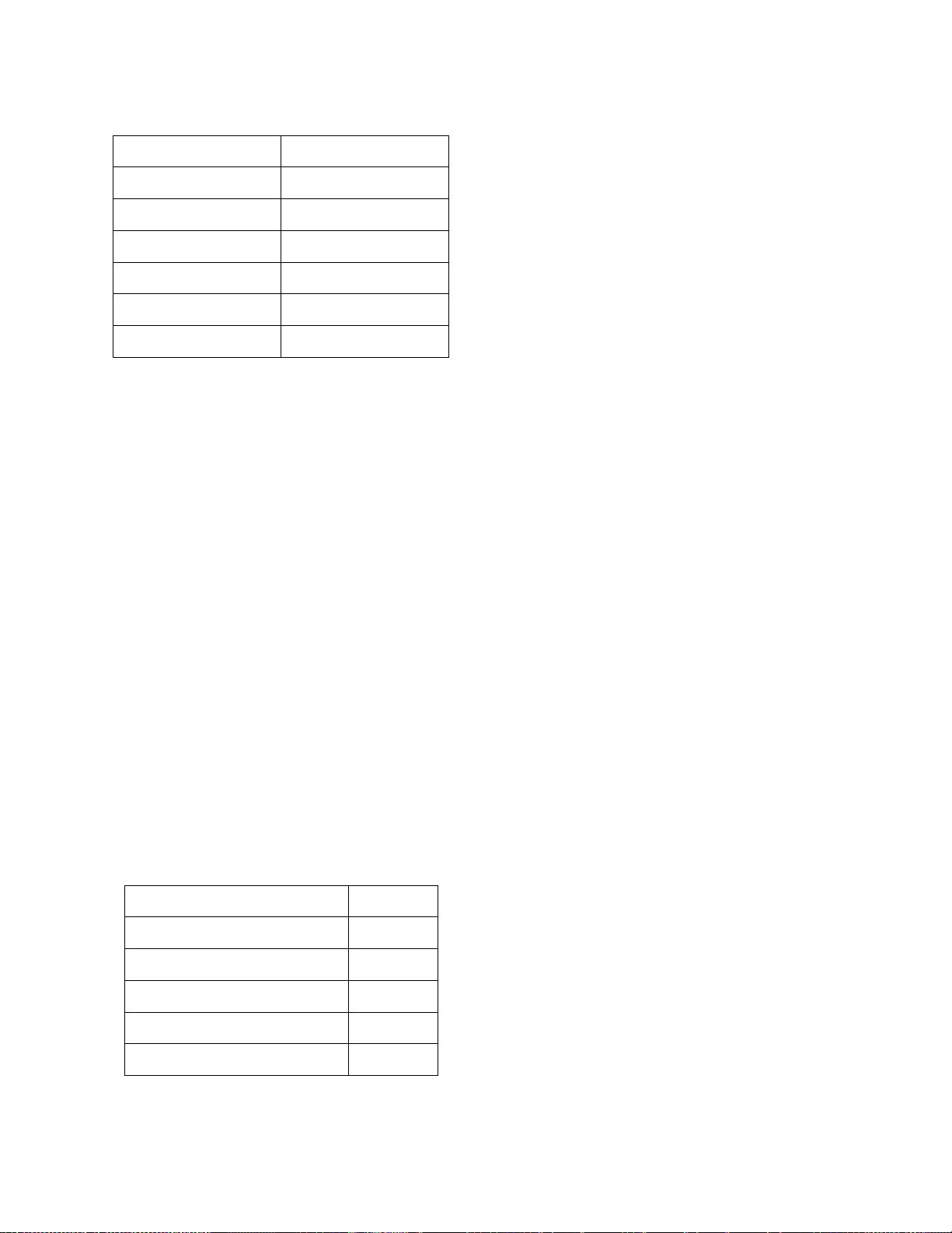
9.3.2 Punch and Die
Operating Clearances
Maintain the following clearances between punch
and die.
Material Thickness
Total Clearance
16 gauge and lighter
.006”
15 gauge - 13 gauge
.010”
3/32” - 5/32”
1/64”
3/16” - 15/32”
1/32”
1/2” - 23/32”
1/16”
3/4” and heavier
3/32”
Table 3
Punch Capacities
You can determine the tonnage required to punch
A36 mild steel (yield strength 36,300 psi, 65,000
psi tensile) by applying the following formulas for
roundor shaped holes. For materials other than
mild steelplease refer to the multiplier table.
Table 5 - Punch Tonnage Requirements
Round Holes
Punch Dia. x Material Thickness x 80 = Tons of
pressure required
Example: How many tons of force do I need to
punch a 3/8” hole in 1/4” mild steel?
.375 x .25 x 80 = 7.5 tons
Shaped Holes
1/3 Punch Perimeter x Material thickness x 80 =
Tons of pressure required
Example: How much force do I need to punch a
3/8”x 1” rectangular hole in 1/4” mild steel?
(.33 x 2.75) x .25 x 80 = 18.1 tons
Material Multiplier
When punching materials other than mild steel
first calculate tonnage as shown above then
apply the multiplier for the listed material.
Aluminum (2024-0)
0.36
Brass (1/4 hard)
0.70
Copper (1/2 hard)
0.52
Steel (50% carbon)
1.60
Steel (cold rolled) (1018)
1.24
Stainless Steel (303)
1.50
Table 4
Page 18
18
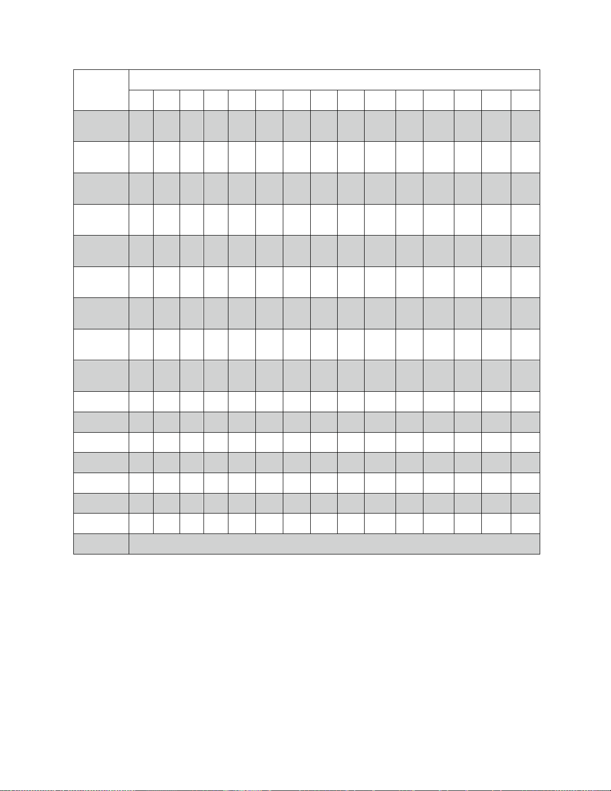
9.3.3 Punch Tonnage Requirement
Stock
Thickness
Hole Diameter
1/8”
3/16”
1/4"
5/16”
3/8”
7/16”
1/2"
9/16”
5/8”
11/16”
3/4"
13/16”
7/8”
15/16”
1”
26 ga.
(.0179)
0.18
0.27
0.36
0.45
0.54
0.63
0.72
0.81
0.90
0.99
1.07
1.16
1.25
1.34
1.43
24 ga.
(.0239)
0.24
0.36
0.48
0.60
0.72
0.84
0.96
1.08
1.20
1.31
1.43
1.50
1.67
1.89
1.91
22 ga.
(.0299)
0.30
0.45
0.60
0.75
0.90
1.05
1.20
1.35
1.50
1.65
1.80
1.95
2.10
2.24
2.39
20 ga.
(.0359)
0.36
0.54
0.72
0.90
1.08
1.26
1.44
1.62
1.80
1.98
2.15
2.33
2.51
2.69
2.87
18 ga.
(.0478)
0.48
0.72
0.96
1.20
1.43
1.67
1.91
2.15
2.39
2.63
2.87
3.11
3.34
3.58
3.82
16 ga.
(.0598)
0.60
0.90
1.20
1.50
1.79
2.09
2.39
2.69
2.99
3.29
3.59
3.89
4.19
4.49
4.78
14 ga.
(.0747)
0.75
1.12
1.49
1.87
2.24
2.61
2.99
3.36
3.73
4.11
4.48
4.86
5.23
5.60
5.97
12 ga.
(.1046)
1.05
1.57
2.09
2.62
3.14
3.66
4.18
4.71
5.23
5.75
6.28
6.80
7.32
7.85
8.57
10 ga.
(.1345)
2.02
2.69
3.36
4.04
4.71
5.38
6.05
6.73
7.40
8.07
8.74
9.42
10.09
10.76
3/16 (.187)
2.81
3.74
4.68
5.61
6.50
7.48
8.42
9.35
10.29
11.22
12.16
13.09
14.03
14.96
1/4 (.250)
5.00
6.25
7.50
8.75
10.00
11.25
12.50
13.75
15.00
16.25
17.50
18.75
20.00
3/8 (.375)
11.25
13.13
15.00
16.88
18.75
20.63
22.50
24.38
26.25
28.13
30.00
1/2 (.500)
20.00
22.50
25.00
27.50
30.00
32.50
35.00
37.50
40.00
5/8 (.625)
31.25
34.38
37.50
40.63
43.75
46.88
50.00
3/4 (.750)
45.00
48.75
52.50
56.25
60.00
7/8 (.875)
61.25
65.63
70.00
1” (1.000)
80.00
Punch Tonnage Requirement Table 5
Page 19
19
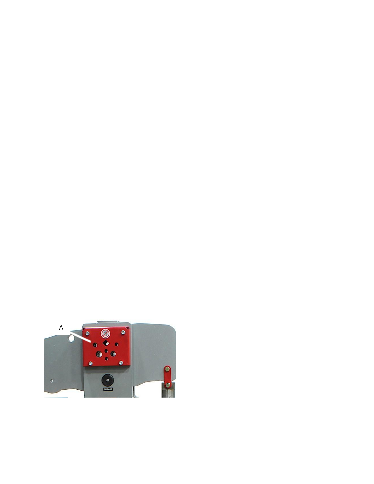
9.4 Rod Shear Operation
Rod Shear will provide distortion and burr free cuts
to mild steel rod and square bar stock as listed in the
Ironworker specification.
The Rod Shearing blades have 6 round and 1
square shearing cavities built into the rocker arm
and frame as a standard station of this ironworker.
The stationary blade is mounted to the vertical frame
plate and the pivoting blade is mounted to the rocker
arm.
Safe Operation
Observe the following guidelines when operating the
Rod Shear.
•
Never exceed the capacities of the machine or
tooling as described in the Ironworker
specifications or listed at the tooling station.
•
Keep the tooling clean.
•
Do not stack cut material.
•
Perform complete shearing operations only –
partial cuts may jam the tooling and could result
in breakage and operator injury.
•
Do not shear more than one rod at a time.
9.4.1 Rod Shear Operation
Referring to Figures 16:
1.
Clear shear station of any tools or debris prior
to powering the machine on.
2.
Turn machine on.
3.
Press the foot pedal to retract the cylinder to
open the rod cavities.
4.
Mark the material for the length needed.
Example: 10” length wanted. Marked at 13.00”
for alignment.
Figure 16
5.
Place rod stock into the tooling guard and
position your cut mark adjacent to the front
surface of the tooling guard. (Fig. 16, A)
6.
Use one or two drops of SAE#30 oil between
the shear blades to extend the life of the blades.
7.
Hold the workpiece firmly, keeping your hands
a safe distance away from the working area. Do
not stand directly behind the workpiece during
the shearing operation, but off to one side.
Once safely positioned, use your foot to press
and hold the cylinder extend pedal. Maintain
pressure until the workpiece has been sheared.
8.
When the cut is complete, release the extend
foot pedal and press the retract foot pedal to
open the rod shear station for the next cut.
Page 20
20
10.0 User-maintenance
Always disconnect power to
the machine before performing maintenance.
Failure to do this may result in serious personal
injury.
Change hydraulic oil and clean the suction screen
after first 3,000 hours of operation. Then change
after every 5,000 hours of operation. Follow local
regulations for disposal of used oil.
Keep table and dies and blades clean and free of
rust. Periodically apply a light coat of SAE30 oil or
equivalent to exposed metal surfaces, such as table,
fences and blades.
Keep blade area free of deposits or shavings, which
can impede cut quality and hasten blade wear.
Inspect blades and punch and dies before each use
for chips, cracks, or other defects which could cause
metal to break off during operation.
When blades become dull, they can be removed
and sharpened.
At the beginning of each workday or shift, but at a
minimum, weekly grease the rocker arm pivot and
the punch ram slide using NLGI#2 grease.
10.1 Blade Inspection
Always disconnect power to
the machine before performing maintenance.
Failure to do this may result in serious personal
injury.
Blades are sharp! Always wear
leather gloves and use caution when working
with the blades.
Failure to do this may result in serious personal
injury.
Figure 18
Shear blades are wearing parts and need to be
maintained or replaced over time. When worn or
chipped, shear blades must be replaced.
Observe the following procedure when maintaining
the Ironworker shear station.
Turn off power to machine by pressing the red
stop/off button and lockout upstream power at the
main electrical panel.
At the back (output side) visually inspect the blades
for defects. If any physical defects are found, the
blades must be replaced.
The blades may be disassembled from the station
and replaced when cut quality is reduced as the
blades become dull.
Maintain 0.010 clearance between fixed and
movable shear blades at all times. Replace the
blades if the gap cannot be restored to .010.
Reference the parts list for replacement blades.
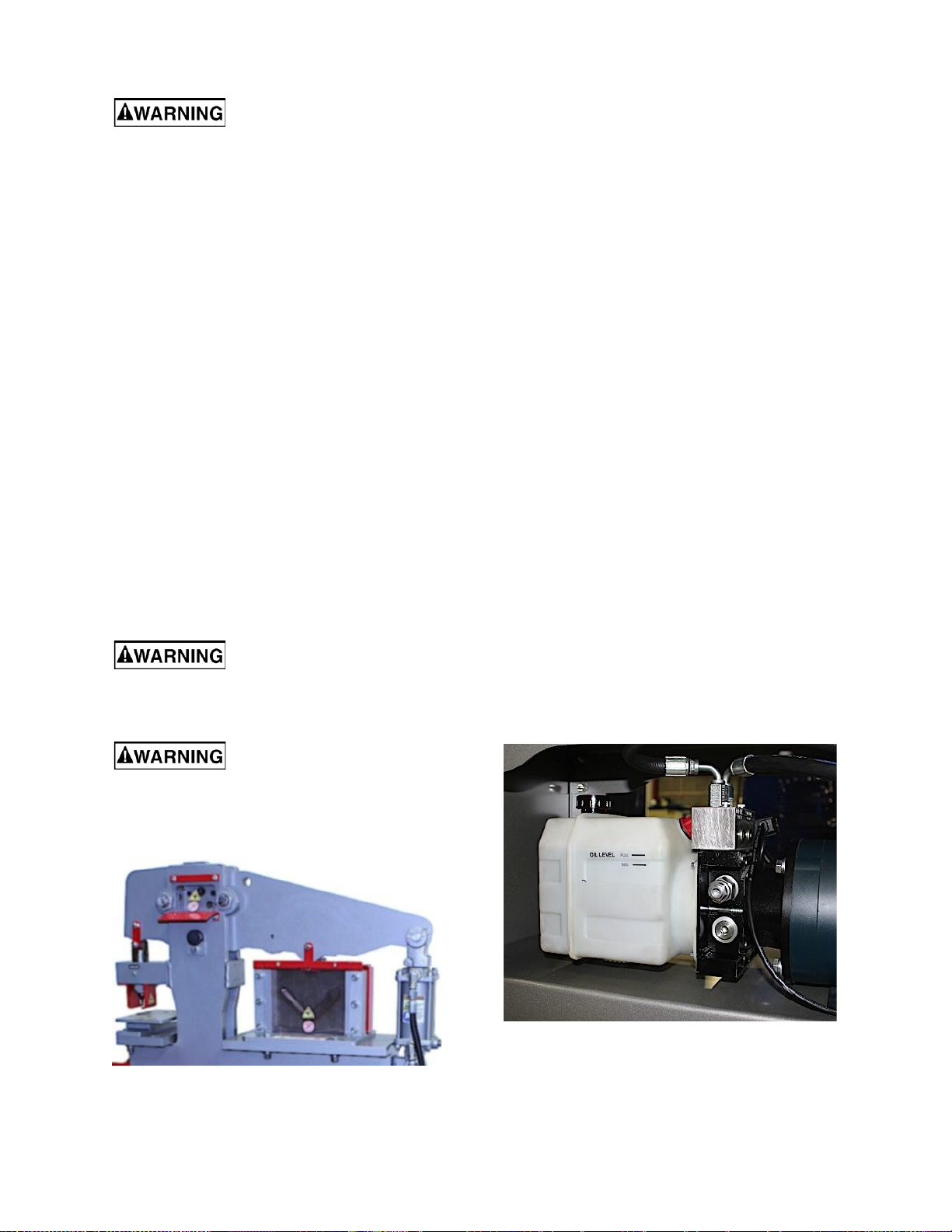
10.2 Hydraulic Oil
The hydraulic oil is the primary medium for
transmitting pressure and also must lubricate the
running parts of the pump.
Use hydraulic oil #46 SHELL BRAND or an
equivalent with similar specifications.
Keep hydraulic reservoir filled between the Full and
Min marks on the reservoir.
Remove the oil fill cap to check the oil level. The
level should be between 1” (25.4mm) and 1/2”
(12.7mm) from bottom of filler neck (C).
A shortage of hydraulic oil will cause hydraulic
system breakdown to major mechanical
components due to overheating.
Every 5000 hours drain the hydraulic oil and fill with
3.0 – 3.2qts. of hydraulic oil. Used oil products must
be disposed of in a proper manner following your
local regulations.
Figure 19
10.3 Oil Disposal
Used oil products must be disposed of in a proper
manner following your local regulations.
Page 21

21
11.0 Troubleshooting
Motor & Electrical
Symptom
Possible Cause
Possible Solution
Machine does not start
or a breaker trips.
Power switch turned off/faulty.
Emergency Stop push-button is
engaged/faulty.
Plug/receptacle is at fault or wired
incorrectly.
Wall fuse/circuit breaker is
blown/tripped.
Motor is at fault.
Toggle Main Power switch to ON/replace.
Rotate clockwise slightly until it pops
out/replace it.
Test for good contacts; correct the wiring.
Ensure circuit size is suitable for this
machine; replace weak breaker.
Test/repair/replace.
Machine stalls or is
overloaded.
Wrong workpiece material.
Plug/receptacle is at fault.
Motor bearings are at fault.
Machine is undersized for the task.
Motor has overheated.
Motor is at fault.
Hydraulic fluid low in reservoir.
Hydraulic fluid pressure too low;
hydraulic pump at fault.
Hydraulic system has leaks or valves
at fault.
Use only metal that is within capacities of
machine.
Test for good contacts; correct the wiring.
Test by rotating shaft; rotational
grinding/loose shaft requires bearing
replacement.
Use sharp tooling; keep workpiece within
the capacities of machine; use cutting
lubricant.
Clean off motor, let cool, and reduce
workload.
Test/repair/replace.
Fill hydraulic reservoir.
Test/adjust for correct hydraulic fluid
pressure, replace pump if necessary.
Check/repair/replace hydraulic hoses,
connections, and valves.
Machine has vibration or
noisy operation.
Motor mount loose/broken.
Motor or component is loose.
Motor fan is rubbing on fan cover.
Motor bearings are at fault.
Tighten/replace.
Inspect/replace stripped or damaged
bolts/nuts and re-tighten with thread locking
fluid.
Tighten/Repair/Replace fan cover.
Test by rotating shaft; rotational
grinding/loose shaft requires bearing
replacement.
*Warning: Some corrections may require a qualified electrician.
Page 22

22
Operations
Symptom
Possible Cause
Possible Solution
Cuts are excessively
ragged or not accurate.
Tooling damaged or dull.
Not using proper station.
Tooling not installed properly.
Cutting stroke not continuous through
the workpiece.
Workpiece moves away from tooling
during operation.
Check/sharpen/replace tooling.
Use the appropriate ironworker station for
your operation
Check/repair tooling installation and
clearances.
Keep pressure on pedal actuator until
workpiece is cut completely through.
Use hold-downs, table guides, and other
devices to ensure workpiece is secure
before cutting.
Tooling not cutting
completely through
workpiece.
Workpiece dimensions not within
capacity of machine.
Tooling is damaged or dull.
Hydraulic pump at fault.
Hydraulic system has leaks or valves
at fault.
Make sure workpiece dimensions are
within machine/station capacity; use
cutting lubricant.
Check/sharpen/replace tooling.
Test/adjust correct hydraulic fluid
pressure; replace pump if necessary.
Check/repair/replace hydraulic hoses,
connections, and valves.
Hydraulic fluid
temperature at/over
160°F (70°C).
Machine cutting at/beyond capacity.
Hydraulic fluid pressure set to high.
Incorrect hydraulic fluid type.
Hydraulic system at fault.
Tum machine OFF and allow hydraulic
fluid to cool; make cuts only with the
capacity of your machine.
Reduce hydraulic fluid relief pressure to
2800 PSI.
Use only one of recommended hydraulic
fluids.
Have a qualified hydraulic service
technician service/repair the hydraulic
system.
Page 23
23
12.0 Optional accessories
These accessory items, purchased separately, can enhance the functionality of your Ironworker. Contact your
dealer to order or call JET at the phone number on the cover.
Punch and Die Sets
Several Punch and Die sets are available from 8 piece, 12 piece, and 32 piece sets.
Punch Station
# 756105 – Punch Assembly for secondary punch station
An additional punch station (duplicate of the standard punch station) which may be installed in the center
table area in place of the bar and angle shear station. This provides two dedicated punch stations, or one
dedicated and one changeable, or both stations changing as needed.
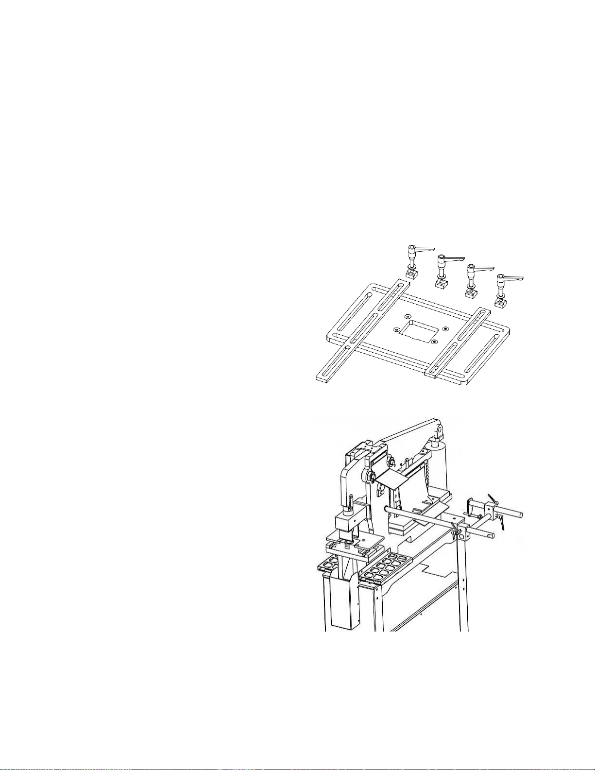
Gauging Table Kit
# 756106 – Gauging Table Kit for punch station
The gauging table will allow for setting of specific
distance setting for the edge of the fence to the center
of the punch for repeatable hole placement.
Material Stop
# 756107 – Material Stop
Adjustable stop for repeatable cut lengths.
13.0 Replacement Parts
Replacement parts are listed on the following pages. To order parts or reach our service department, call 1-800274-6848 Monday through Friday, 8:00 a.m. to 5:00 p.m. CST. Having the Model Number and Serial Number of
your machine available when you call will allow us to serve you quickly and accurately.
Page 24
24
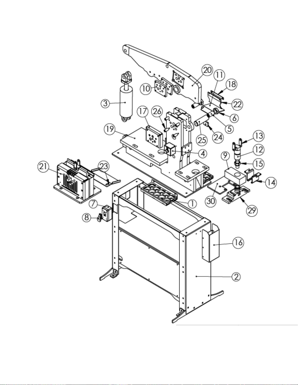
13.1 45T Iron Worker – Exploded View
Page 25

25
13.2 45T Iron Worker – Parts List
Index No Part No Description Size Qty
1 ................ AC1920 ..................... Punch & Die Holder ........................................................................................ 1
2 ................ Base Assy. .................. JIW-45T Base Assembly – JIW-45T ........................................................................ 1
3 ................ CY4500 ..................... Cylinder.................................................................... 3.5" Bore x 4" Stroke ...... 1
4 ................ E-Stop ....................... Emergency Stop ............................................................................................. 1
5 ................ GIB0128-04GL ……. . Gib Assembly Grease Less ............................................................................ 2
6 ................ JIW1204…………....... Nut – Gib Pin ................................................................................................. 2
7 ................ HS152 ....................... Switch Box ...................................................................................................... 1
8 ................ HS153 ....................... Electrical Switch .............................................................................................. 1
9 ................ JIW1011 .................... Punch Head Guide – JIW-45T ........................................................................ 1
10 .............. JIW1132 .................... Blade Rod Shear – JIW-45T ........................................................................... 2
11 .............. JIW1136 .................... Drop Table – JIW-45T .................................................................................... 1
12 .............. JIW1143 .................... Punch Head – JIW-45T .................................................................................. 1
13 .............. JIW1146 .................... Punch Link – JIW-45T..................................................................................... 2
14 .............. JIW1154 .................... Stripper – JIW-45T .......................................................................................... 2
15 .............. JIW1168 .................... Punch Nut – JIW-45T ..................................................................................... 1
16 .............. JIW1175 .................... Slug Receptacle – JIW-45T ............................................................................ 1
17 .............. JIW1176 .................... Rod Shear Guard – JIW-45T .......................................................................... 1
18 .............. JIW1177 .................... Guard Strip – JIW-45T .................................................................................... 1
19 .............. JIW1190 .................... Frame – JIW-45T ............................................................................................ 1
20 .............. JIW1191 .................... Center Assembly – JIW-45T ........................................................................... 1
21 .............. JIW1192 .................... Shear Assembly – JIW-45T ............................................................................ 1
22 .............. JIW1194 .................... Drop Guard. Rod Shear – JIW-45T ................................................................ 1
23………….JIW1196………………Drop Table Shear JIW-45T ............................................................................ 1
24………….JIW1208……………...Ret Block Center Pin ...................................................................................... 1
25 ................ PH124-01 ................... Pin - Whale Pivot ......................................................................................... 1
25 ............... JIW1178 .................. Standoff Rod Shear – JIW-45T ....................................................................... 4
26 ............... JIW1206.................... Pedestal Die Table – Base ............................................................................. 1
27 ............... JIW1205.................... Pedestal Die Table – Top ............................................................................... 1
HE-DS100-DG...........Foot Pedal.............................NOT PICTURED. ................................................. 1
JIW1988....................Handle, Foot Pedal................ NOT PICTURED. ............................................... 1
HK1165.....................Hose Kit..................................NOT PICTURED................................................. 1
DE-JET203...............JET-203 Badge.......................NOT PICTURED. ............................................... 1
DE-JIW1188.............Serial/Warning Plate................NOT PICTURED. ................................................ 1
Page 26
26
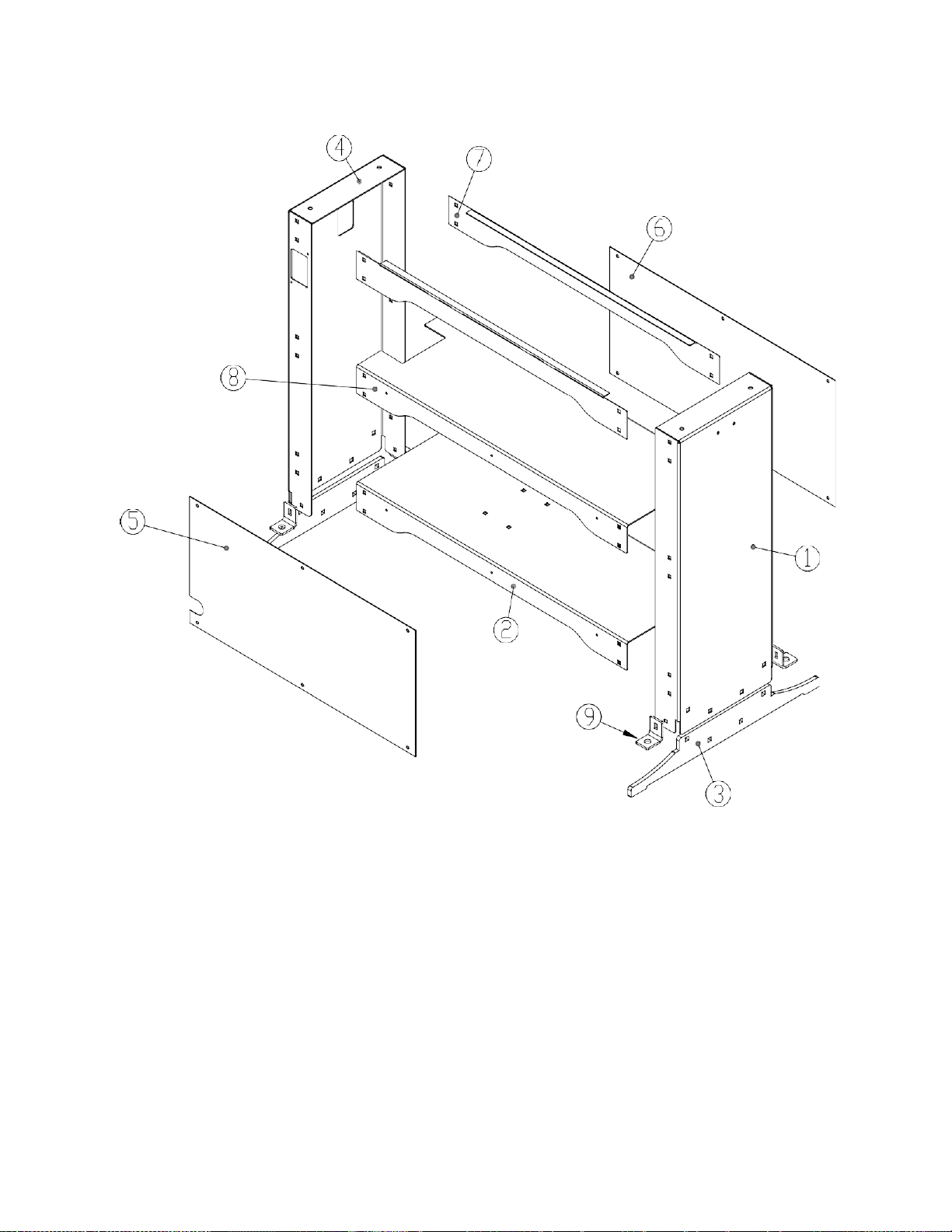
13.2.1 Base Assembly – Exploded View
13.2.2 Base Assembly – Parts List
Index No Part No Description Size Qty
1 ................ JIW1152 .................... Base Right Side – JIW-45T ....................................................................................
1
2 ................ JIW1153 .................... Base Motor Shelf – JIW-45T ...................................................................................
1
3 ................ JIW1169 .................... Base Leg – JIW45T .................................................................................................
2
4 ................JIW1170 ..................... Base Left Side – JIW-45T .......................................................................................
1
5 ................ JIW1171 .................... Front Cover – JIW-45T ............................................................................................
1
6 ................ JIW1172 .................... Back Cover – JIW-45T ............................................................................................
1
7 ................ JIW1182 .................. Valance Cover – JIW-45T ................................................................................. 2
8 ................ JIW1183 .................... Base Shelf – JIW-45T .............................................................................................
1
9 ................ JIW1185 .................. Tie Down – JIW-45T .............................................................................................
4
Page 27
27
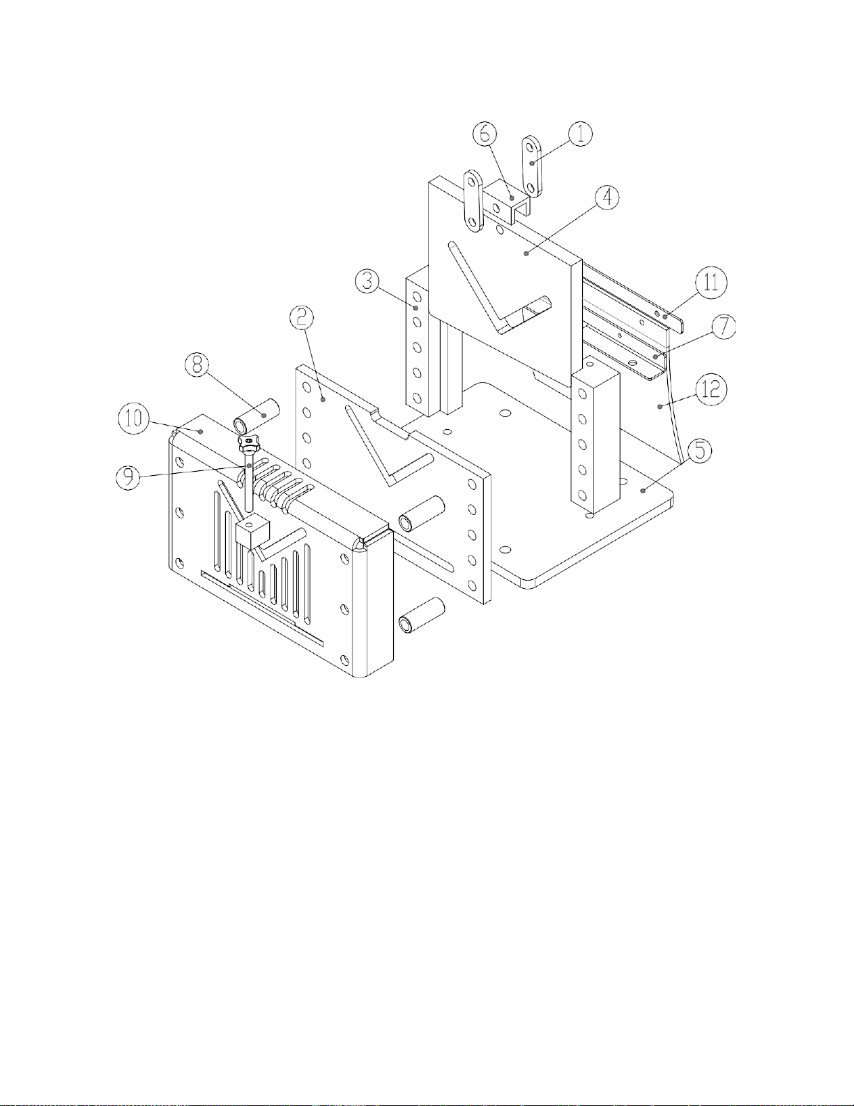
13.2.3 Shear Station – Exploded View
13.2.4 Shear Station – Parts List
Index No Part No Description Size Qty
1 ................ JIW1146 .................... Punch Link – JIW-45T ................................ .................................................. 2
2 ................ JIW1157 .................... Blade Fixed – JIW-45J ................................................................................. 1
3 ................ JIW1158 .................... Blade Guide – JIW-45 .................................................................................. 2
4 ................ JIW1159 .................... Blade Movable – JIW-45T ............................................................................ 1
5 ................ JIW1160 .................... Base Plate – JIW-45 ..................................................................................... 1
6 ................ JIW1161 .................... Push Block – JIW-45T .................................................................................... 1
7 ................ JIW1179 .................... Shear Back Guard Mount – JIW-45T ........................................................... 1
8 ................ JIW1180 .................... Shear Standoff – JIW-45T ............................................................................ 4
9 ................ JIW1181 .................... Angle Hold Down Adjuster – JIW-45T ......................................................... 1
10 .............. JIW1186 .................... Multi-Shear Guard Assembly – JIW-45T ..................................................... 1
11 .............. JIW1187 .................... Guard Strip – JIW-45T ................................................................................. 1
12 .............. JIW1193 .................... Drop Guard, Flat/Angle – JIW-45T............................................................. 1
Page 28
28
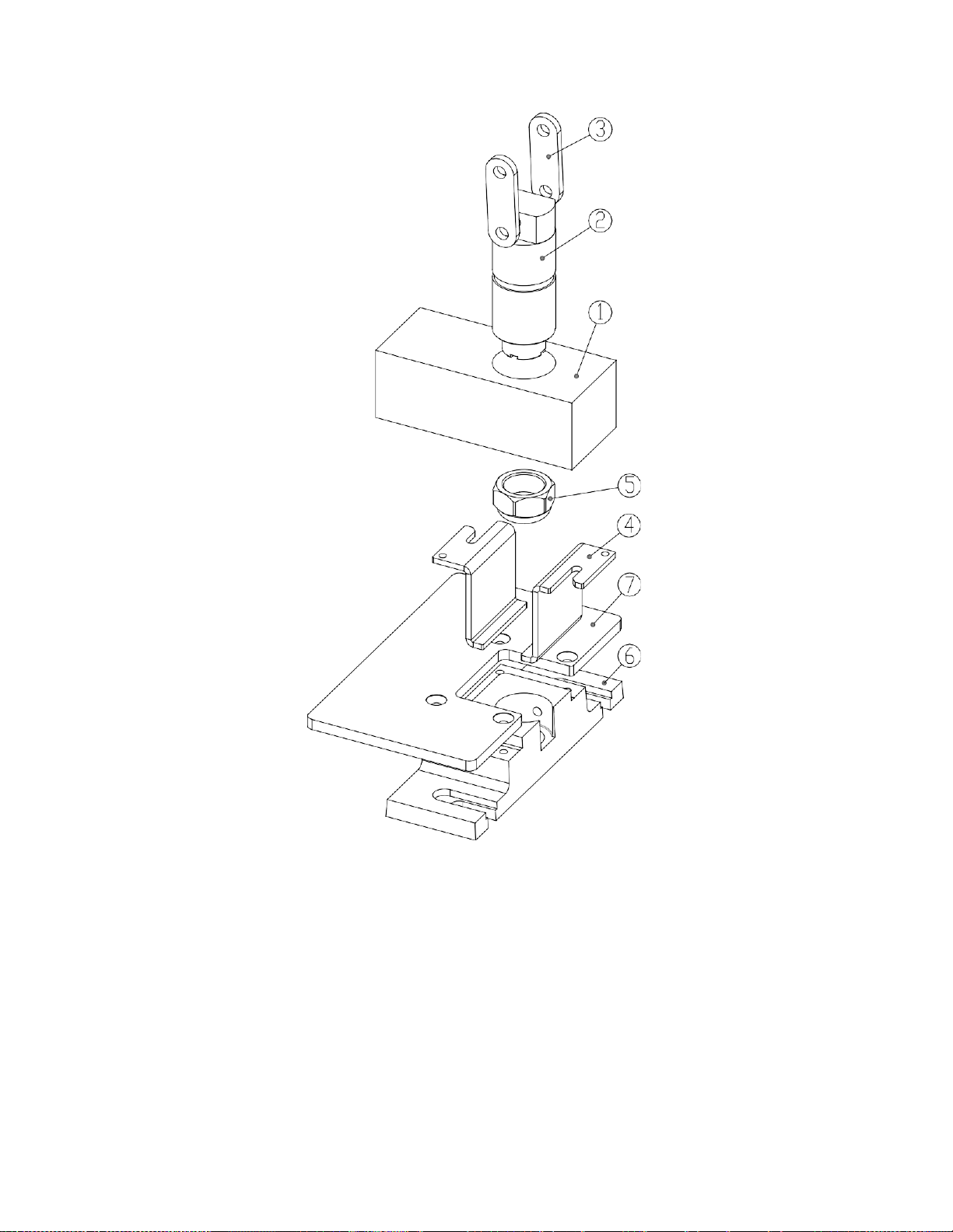
13.2.5 Punch Station (Standard and Optional) – Exploded View
13.2.6 Punch Station (Standard and Optional) – Parts List
Index No Part No Description Size Qty
.................. 756105 ...................... Full Punch Station, Replacement or for Center Station ................................... 1
1 ................ JIW1011 .................... Punch Head Guide – JIW-45T ........................................................................ 1
2 ................ JIW1143 .................... Punch Head – JIW-45T ................................................................................... 1
3 ................ JIW1146 .................... Punch Link – JIW-45T ............................................................................................
2
4 ................ JIW1154 .................... Stripper – JIW-45T .......................................................................................... 2
5 ................ JIW1168 .................... Punch Nut – JIW-45T ...................................................................................... 1
6 ................ JIW1206..................... Pedestal Die Table – Base ............................................................................. 1
7 ................ JIW1205 .................... Pedestal Die Table – Top ........................................................................... 1
Page 29
29
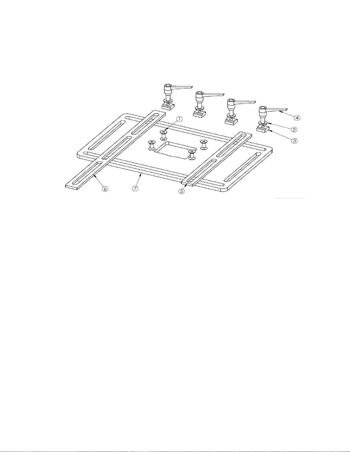
13.2.7 Gauging Table Kit (Optional) – Exploded View
13.2.8 Gauging Table Kit (Optional) – Parts List
Index No Part No Description Size Qty
.................. 756106 ...................... Gauging Table Kit – JIW-45T Option .............................................................. 1
1 ................ 24254 ........................ Flat Head Socket Cap Screw................................... 5/16”-18x3/4” .................. 4
2 ................ 33082 ........................ Flat Washer ............................................................. 3/8” ...................................... 4
3 ................ HM-3163955 ............. T Nut........................................................................ 3/8” .......................................... 4
4 ................ HM-MA38161 ............ Handle Adjustable ................................................... 3/8”-16x1” ....................... 4
5 ................ HM900-01 ................. Fence – Short ................................................................................................. 1
6 ................ HM900-02. ................. Fence – Long ............................................................................................... 1
7 ................ JIW1207.................... Pedestal Gauging Table ............................................................................. 1
Page 30
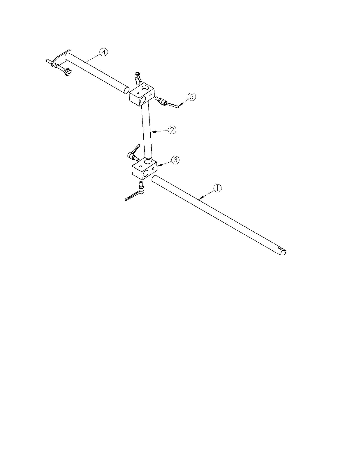
30
13.2.9 Material Stop (Optional) – Exploded View
13.2.10 Material Stop (Optional) – Parts List
Index No Part No Description Size Qty
.................. 756107 ...................... Material Stop Option ................................................................................................
1
1 ................ HM667....................... Back Gauge Rod ..................................................... 1” x 26” ...............................
1
2 ................ HM5207-01 ............... Auto Cut Short Slide Bar ......................................... 12” .................................. 1
3 ................ HM5192..................... Auto Cut Cross Clamp .............................................................................................
2
4 ................ HB186 ....................... Stop Arm Assembly .................................................................................................
1
5 ................ HM-MA38161 ............ Handle, Adjustable .................................................. 3/8”-16x1” .................. 4
Page 31

31
14.0 Warranty and service
JET warrants every product it sells against manufacturers’ defects. If one of our tools needs service or repair, please
contact Technical Service by calling 1-800-274-6846, 8AM to 5PM CST, Monday through Friday.
Warranty Period
The general warranty lasts for the time period specified in the literature included with your product or on the official
JET branded website.
• JET products carry a limited warranty which varies in duration based upon the product. (See chart below)
• Accessories carry a limited warranty of one year from the date of receipt.
• Consumable items are defined as expendable parts or accessories expected to become inoperable within a
reasonable amount of use and are covered by a 90 day limited warranty against manufacturer’s defects.
Who is Covered
This warranty covers only the initial purchaser of the product from the date of delivery.
What is Covered
This warranty covers any defects in workmanship or materials subject to the limitations stated below. This warranty
does not cover failures due directly or indirectly to misuse, abuse, negligence or accidents, normal wear-and-tear,
improper repair, alterations or lack of maintenance. JET woodworking machinery is designed to be used with Wood.
Use of these machines in the processing of metal, plastics, or other materials outside recommended guidelines may
void the warranty. The exceptions are acrylics and other natural items that are made specifically for wood turning.
Warranty Limitations
Woodworking products with a Five Year Warranty that are used for commercial or industrial purposes default to a
Two Year Warranty. Please contact Technical Service at 1-800-274-6846 for further clarification.
How to Get Technical Support
Please contact Technical Service by calling 1-800-274-6846. Please note that you will be asked to provide proof
of initial purchase when calling. If a product requires further inspection, the Technical Service representative will
explain and assist with any additional action needed. JET has Authorized Service Centers located throughout the
United States. For the name of an Authorized Service Center in your area call 1-800-274-6846 or use the Service
Center Locator on the JET website.
More Information
JET is constantly adding new products. For complete, up-to-date product information, check with your local distributor
or visit the JET website.
How State Law Applies
This warranty gives you specific legal rights, subject to applicable state law.
Limitations on This Warranty
JET LIMITS ALL IMPLIED WARRANTIES TO THE PERIOD OF THE LIMITED WARRANTY FOR EACH PRODUCT.
EXCEPT AS STATED HEREIN, ANY IMPLIED WARRANTIES OF MERCHANTABILITY AND FITNESS FOR A
PARTICULAR PURPOSE ARE EXCLUDED. SOME STATES DO NOT ALLOW LIMITATIONS ON HOW LONG AN
IMPLIED WARRANTY LASTS, SO THE ABOVE LIMITATION MAY NOT APPLY TO YOU.
JET SHALL IN NO EVENT BE LIABLE FOR DEATH, INJURIES TO PERSONS OR PROPERTY, OR FOR
INCIDENTAL, CONTINGENT, SPECIAL, OR CONSEQUENTIAL DAMAGES ARISING FROM THE USE OF OUR
PRODUCTS. SOME STATES DO NOT ALLOW THE EXCLUSION OR LIMITATION OF INCIDENTAL OR
CONSEQUENTIAL DAMAGES, SO THE ABOVE LIMITATION OR EXCLUSION MAY NOT APPLY TO YOU.
JET sells through distributors only. The specifications listed in JET printed materials and on official JET website are
given as general information and are not binding. JET reserves the right to effect at any time, without prior notice,
those alterations to parts, fittings, and accessory equipment which they may deem necessary for any reason
whatsoever. JET® branded products are not sold in Canada by JPW Industries, Inc.
Product Listing with Warranty Period
90 Days – Parts; Consumable items
1 Year – Motors; Machine Accessories
2 Year – Metalworking Machinery; Electric Hoists, Electric Hoist Accessories; Woodworking Machinery used
for industrial or commercial purposes
5 Year – Woodworking Machinery
Limited Lifetime – JET Parallel clamps; VOLT Series Electric Hoists; Manual Hoists; Manual Hoist
Accessories; Shop Tools; Warehouse & Dock products; Hand Tools; Air Tools
NOTE: JET is a division of JPW Industries, Inc. References in this document to JET also apply to JPW Industries,
Inc., or any of its successors in interest to the JET brand.
Page 32

3
427 New Sanford Road
LaVergne, Tennessee 37086
Phone: 800-274-6848
www.jettools.com
 Loading...