

Page 1
ANHD20
MOBILE OMNI-DIRECTIONAL WIDEBAND ANTENNA
Installation and Operation Manual
PATENT PENDING
Page 2
INTRODUCTION
Thank you for choosing a Jensen. We’ve tried to make the instructions in this owner’s
manual clear and easy to follow. If you take a few minutes to look through it, you’ll learn how to use
all of the features of your new Jensen antenna for maximum enjoyment.
Contents
Precautions………………………………………………………………………………………….….1
Preparation…………………………………………………………………………………………..….1
Installation………………………………………………………………………………………...…1- 4
Operation………………………………………………………………………………………….……5
Specifications…………………………………………………………………………………………..5
System Layout………………………………………………………………………………………….6
Troubleshooting………………………………………………………………………………………...7
PRECAUTIONS
• Proper Power Supply
This product is designed to operate with a 12 volt DC, negative ground power system
• Use Authorized Service Centers
Do not attempt to disassemble or adjust this precision product. Contact a professional for service
• Do not install couplers or splitters between the wall plate and antenna
Installation of any item on this cable lead may cause a short. This cable provides power to the
Antenna preamp.
• Power Supply should disconnected during installation
Connect all coax cable connections before connecting +12VDC wire to the wall plate. The switch
should be in the OFF position when connecting/disconnecting cables.
• All coaxial cable used should be RG-6U for optimal performance
• Painting the Antenna is not recommended and may affect performance
• Do not use solvents to clean antenna. Use only mild soap and water.
PREPARATION
Please read all instructions before beginning the installation.
Tools and Supplies
• Drill or Battery Driver with a #2 Phillips Bit
• ½” Drill Bit
• Caulking Gun
• Tube of Approved Exterior Roof Caulk
• RG-6U Coaxial Cable
• 16AWG Power & Ground Wire
ANTENNA INSTALLATION
1. Remove all packaging contents from shipping box.
2. Locate the Antenna Housing
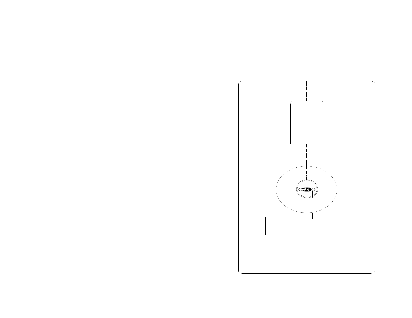
3. Determine a suitable location to mount the antenna. This location should allow for approximately 24”
of clearance around the antenna. Avoid close proximity to other roof mounted objects (AC, Vents, &
Roof Edges). See Figure 1 below.
RO O F VIEW
AC
24"
V EN T
N O TE : A N TE N N A S H O UL D B E M O U N TE D A S C LOS E T O
TH E CEN T ER O F T HE R O O F A S P O S SIB LE F O R B E ST
R EC E P TIO N.
TH E AN T EN N A SHO U LD N O T B E L O CA TE D W ITH IN 2 4"
O F A N Y O B JE C T O R ROO F E D G E.
FIG U RE 1
2
Page 3
ANTENNA INSTALLATION
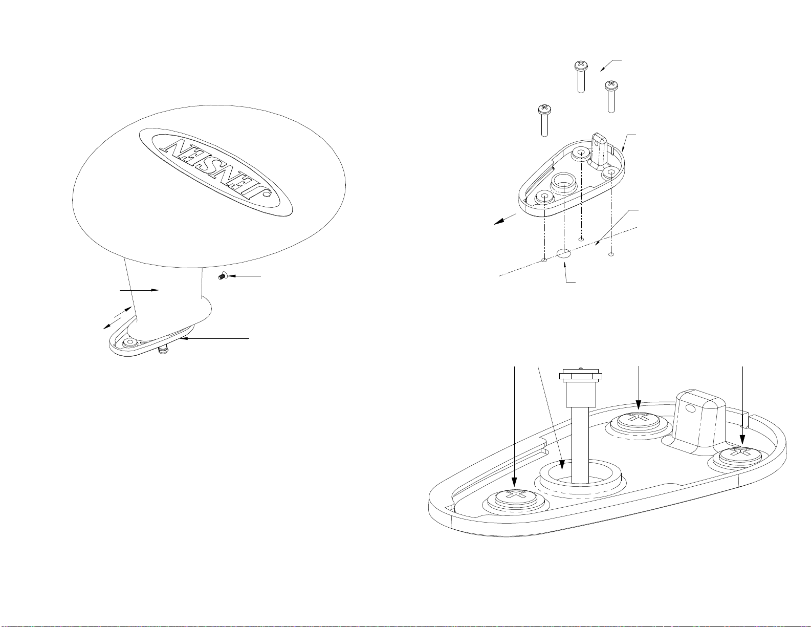
4. Remove metal base from plastic housing by removing the lock screw and sliding the base away from
the plastic stalk. Mark hole locations on roof. Drill 5/8” hole for the coax cable. Pre-drill the 3
mounting screws holes with a 1/8” bit. Route RG6 Coax from wall plate through hole. See Figures
2, 3, & 4.
FRONT OF
VEHICLE
3 - 1/4"x14 SCREWS (INCLUDED)
MOUNTING BASE
APPLY APPROVED
CAULKING COMPOUND
AROUND THE 4 HOLES
LOCK SCREW
ANTENNA
MOUNTING BASE
FIGURE 2
5. Apply approved caulking compound around all holes. Place base over holes and caulking. Secure
base using the included 3 screws. Apply approved caulking compound to screw heads and fill ½”
hole with caulking compound. See Figure 4
6. Connect the 2 coax cables ensuring the fitting is snug (Do Not Over tighten). Reinstall the plastic
housing onto the base. Reinstall the lock screw.
7. Additional caulking compound may be applied to the outside seam of the base. Please note there is a
moisture weep hole at the rear of the base. If proper sealing techniques are used (as described in
Step 5) you should not need to add additional caulking around the base.
NOTE: The Caulking compound used should be approved for the type of vehicle and environment.
Check OEM recommendations for your vehicle. Material should be a non-hardening type such as
Butyl caulking.
CENTER LINE
DRILL 5/8" HOLE
OF ROOF
FIGURE 3
A P P L Y A P P R O V E D C A U L K IN G
C O M P O U N D 4 P L A C E S
F IG U R E 4
3
Page 4

WALL PLATE INSTALLATION
1. The wall plate/power supply assembly may be mounted in most electrical outlet/switch boxes. The
plate can also be mounted without an electrical box. This mounting method requires a hole 2.75” x
2.0”. Route 2 16AWG wires to this hole from the 12VDC source. Also route all coax cables to this
hole. See Figure 5.
2. Connect all coax cables to the appropriate wall plate pigtails. Each pigtail has a label for
identification. Connect the cable from the roof antenna to the “ANTENNA IN”. Connect the “TV2
OUT to TV input. “RADIO OUT” goes to the input of the AM/FM radio. “CABLE IN” connects to
the Park Cable Input. See Figure 6. (Do Not Over tighten)
3. After connecting all coax cables, connect +12VDC wire to the + male spade terminal on the circuit
board (marked with a red dot) using a ¼” Insulated Female Spade Terminal. Then connect the
ground wire (marked with a black dot) using the same type terminal. See Figure 6.
6. Install the wall plate using a two #6 Flat Head screws.
7. Connect main TV to the TV1 output on the front of the wall plate.
INTERIOR WALL
2.0"
To Second TV
To Antenna
ANT ENNA
IN
TV2
OUT
RADIO
OUT
CAB LE
IN
To AM/FM Radio
To Park Cable
ROUTE ALL POWER/GROUND WIRES
AND COAX CABLES THROUGH THIS HOLE
FIGURE 5
* Recommendation of RG-6U cable type with a maximum length of
10 feet between Plate and Antenna.
2.75"
0V GROUND INPUT
FIGURE 6
#6 FLAT HEAD SCREW
FIGURE 7
+12VDC INPUT
4
Page 5

OPERATION
1. Select the desired source by moving the switch located on the front of the wall plate. Select either
“AIR” or “CABLE”. AIR will activate the roof mounted antenna which will provide over-the-air
TV and AM/FM reception. Selecting CABLE will enable you to receive signals from your external
Cable Service provider and AM/FM reception. Selecting “OFF” will disable the system completely
and is recommending when the vehicle is not in use or storage. Note the Red LED indicator will be
On in the “AIR” & “CABLE” positions. See Figures 8 & 9.
2. Next turn on all TV’s and access your on screen menu. (refer to your TV owner’s manual). If you
selected “AIR” ensure that TV tuner is set to receive over-the-air ATSC/NTSC signals. Activate the
TV’s auto programming sequence to scan / store available channels.
3. If you selected “CABLE”, then set your TV tuner to cable and activate the TV’s auto programming
sequence to scan / store available channels.
4. The 7.5 Amp DC Receptacle is designed to power DC TV’s or other small amperage DC devices.
The 7.5A fuse located on the front of the wall plate protects this receptacle and the power to the roof
antenna. If this fuse blows then the antenna will not work. Do not connect high current devices.
5. Other wall plates do not have the DC receptacle and are fused at 1 Amp to protect the electronics.
*Warning: Replace Fuse with the same Fuse type & current
rating. Failure to do so may cause damage and void warranty.
SPECIFICATIONS
POWER SUPPLY……………………………………………….9 – 16 VDC negative ground at 85mA
IMPEDANCE……………………………………………… ………………………………… ….....75Ω
FREQUENCY RANGE………………………..40 – 850MHz, 500 – 1700KHz (AM, FM, VHF, UHF)
E-PLANE DIRECTIVITY…………………………………………………………....Omni-Directional
GAIN…………………………………………………………………………………..….15dB (typical)
GAIN FLATNESS………………………………………………………………….……0.5dB (typical)
OIP3………………………………………………………………………………..…80dBmV (typical)
OPERATING TEMPERATURE…………………………………………….-40C ~ 85C (-40F~ 185F)
OVERALL DIMENSIONS……………………………………………….8”(H) x 12.75”(W) x 14”(D)
Specifications subject to change without notice.
This device complies with Part 15 of the FCC Rules. Operation is subject to the following 2 conditions:
(1) This device may not cause harmful interference.
(2) This device must accept any interference received, including interference that may cause undesired
operation.
NOTE: The manufacturer is not responsible for any radio or TV interference caused by unauthorized
modifications to this equipment. Such modifications could void the user’s authority to operate this
equipment.
7.5 AMP MAX
DC RECEPTACLE
7.5 AMP MINI
ATM FUSE
1 AMP MINI
ATM FUSE
ANWP12V
LED INDICATOR
SWITCH
TV1 OUTPUT
CONNECT TO TV
FIGURE 8
ANWP
LED INDICATOR
SWITCH
TV1 OUTPUT
CONNECT TO TV
FIGURE 9
5
Page 6

JEN SEN SYSTEM LA YOUT
ANHD20
TV1
AMPLIFIED
SIG N AL
TV 2
RG-6U
CABLE
(M ax 10 feet
recom mended)
AM /FM Rad io
Fem ale Motorola
AM /F M Rad io M ale Motorola
to F con nector (P /N AN 3FM )
AN TEN NA
IN
TV2
OU T
RADIO
OU T
AI R OFF CABL E
CA BLE
IN
Park Cable Input
W ALL P LATE (ANWP or ANWP12V)
FU S E
Provides power to the Antenna via the
coaxial cable center condu ctor
6
Page 7

TROUBLESHOOTING
For technical assistance, please visit www.asaelectronics.com
Problem Cause Corrective Action
No TV reception on AIR No 12VDC power at PCB Check power and ground connections with test light
Blown Fuse Check fuse in wall plate and main supply
Bad coax connection Check to ensure cables are connected properly at TV & wall plate
Wall Plate Switch in wrong position Move switch to AIR position
TV tuner not set to AIR Check TV tuner status in on screen menu
LED Indicator is Off No 12VDC power at PCB Check power and ground connections with test light
Blown Fuse Check fuse in wall plate and main supply
Shorted coax connection Check Antenna coax connection for short
Switch in wrong position Check switch position
No TV reception on Cable No 12VDC power at PCB Check power and ground connections with test light
Blown Fuse Check fuse in wall plate and main supply
Bad coax connection Check to ensure cables are connected properly at TV & wall plate
Wall Plate Switch in wrong position Move switch to CABLE position
TV tuner not set to CABLE Check TV tuner status in on screen menu
No power at DC socket No 12VDC power at PCB Check power and ground connections with test light
Blown Fuse Check fuse in wall plate and main supply
ASA ELECTRONICS CORPORATION
www.jensenrvdirect.com
www.asaelectronics.com
© 2010 ASA Electronics Corporation
v.102809
7
 Loading...