

Page 1
A1000
For
technical
of
Technical
assistance
with
Power
2x50
2 CHANNEL
INPUT SENSITIVITY CONTROL
2-8 OHM OPERATION
HIGHILOW
Owners
and
Assistance
the
operation
Amplifier
WAITS
Manual
Installation
the AI 000, call 1-800-323-0221
J
RMS
POWER
LEVEL INPUTS
Instructions
or
instaIlation
Page 2
1
j
r
i
!
A
1000
Amplifier
Thank
Thank
for
Easy
Jensen
maximum enjoyment.
You
you
your
car.
Operation
products arc
for buying a Jensen product. Congratulations
~
read this manual
simple
and easy to orerate. This manual explains how to usc the
~
installation and operation.
Installation
For
proper
step instructions as
ter.
patience, and the ability to
consider turning the
operation,
Most
installations arc straightforward and can be handled
Technical
For technical assistance
For
Your
In case
to return the unit for any reason, always enclose the bill
Records
your
Jensen amplifier requires service, youlmust have the original. dated bill
it's
very important that the unit
clear
as possible, but we
follow instructions. However, ir you lack. one
installation
Assistance
will}
the
job
over to
operation
don't
know
an
authorized Jensen dealer/installer.
or
installation
Important
Here are two important points you must know;
Wirjng.
damaged. Follow the installation instructions carefully
technician.
Fuses.
wrong rated
If
",:,jring
connections are made incorrectly, the unit will not operate properly and
If
you have to replace a fuse. make sure the new fuse
fuse could damage the unit.
on
your investment
be
installed correclly.
about any unusual circumstances you may encoun-
by
a do-it-yourselfer with reasonable tools,
of
the A 1000 power amplifier, call I
of
sale with the product.
or
have the instaIlation handled by an experienced
is
,the
correct type and amperage. Using the
or
in
quality
AHrn
We
tried to
two
of
these requirements.
of
sound
reproduction
for
make
OUT
step-by-
~800-323~0221.
saie.
If
it is necessary
it
could
be
Table
General
Audio Amplifiers
Inputs
Input Sensitivity
HighLevel
Power
Power Light
Parts
of
Contents
Information
and
Input Harness - Power Wires
...
and
Installation
Troubleshooting
Wiring
Instructions
Alternative
Specifications
-Installation
Outputs
Control-
Tools
...
Instructions
................. .
Wiring.
and
..
and Location Requirements - Selecting Speakers
Speaker Terminals - Low Levellnpu! RCA
...
.
. .......................................... 5
............................................ 6
. ................................................... 7
Warranty
................ .
2
Connectors-
. .................... 5
.
. ... 3
.... 4
.... 4
...................
..5
8
Page 3
A1000
Amplifier
General
The
Jensen AI 000
• High-level inputs
• Low-level inputs
•
Input
sensitivity control
• Remote tum
Electronic protection circuitry to protect the aITlplifier from short circuit,
50
watts RMS per channel
125 watts
250
walts
Bridgeable design
Audio
Amplification offers two advantages:
•
• Louder. Many automotive radios provide four
Amplifiers
Optimum
and richer, even at low volume levels.
channel (125 watts bridged), the A I (X)() can be played substantial
powerful speakers.
Information
(XJwer
amplitier
(speaker
(RCA
on/off
RMS bridged
peak
sound at low
level)
phono)
volume
is
a two-channel. 25G-watt
,
levels.
The
A I ()(X) amplifi.er can
to
10
peak
watts at
automotive amplifier.
maximum
The A 1<XXJ
DC
offset
and
make
the sound
power. At
Jy
louder, permitting the use
of
your
50
watts
thermal
receiver
RMS
of
includes:
overload
fuller
per
more
installation
The
A1000 amplifier's
locations arc:
Under a scat
In
the trunk
Under the
selecting a location, remember that amplifiers generate heat.
When
around
the amplifier. Do not
Selecting
The
Jensen
component
maximum
bass
and
Location
compact
dashboard
cover
Requirements
design allows greater tlexibility
the A 1
()(X)
with carpets
Speakers
AICXX)
systems and 213-way designs. Jensen offers a full line
amplifier provides [he tlexibility
pcrfonnance
when used with the A I (X){).
to
in
mounting.
Select
or
enclose it behind interior trim panels.
power
significantly upgraded speakers
of
loud
See
your local authorized Jensen
Some
a location where
speakers
possible
designed
dealer
mounting
air
can
such
as
to
deliver
for
circulate
Jensen
details.
Page 4
A
1000
Amplifier
Inputs
and
Outputs
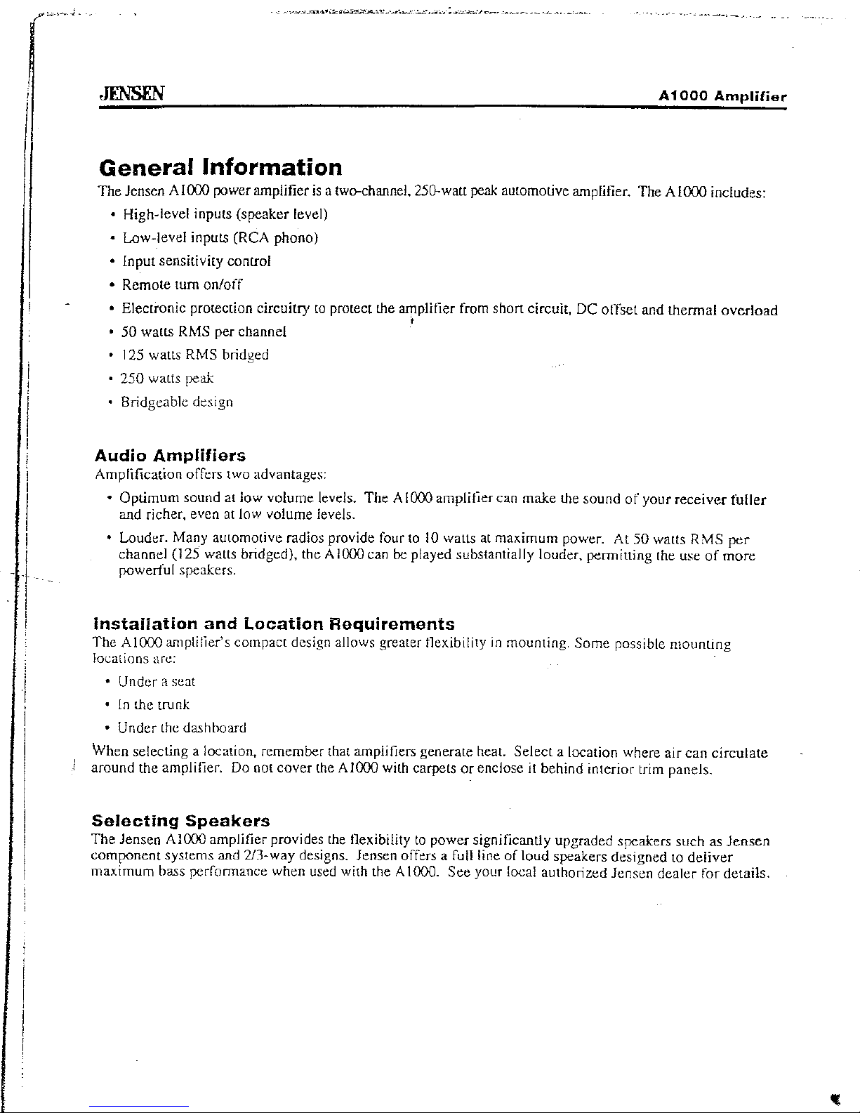
Input
Sensitivity
Control
Adjust the
s~nsilivity
to
the
input level.
lOW
INPUT
Speaker
Terminals
Connect to
~:;peakers.
SPEAKER OUTPUT: CAUTION'
DO
NOT
CONNECT l-A."<O
R-
HI
lEVEL
INPUT
TOGEfilER OR TO GROUND
Low
Level
Input
RCA
Connectors
Connect RCA cables from your receiver
(if
equipped)
to
these RCA jacks. For the least
harmonic distortion, low level inputs are
recommended.
Important:
Do
not
connect
both
high
level
and
low
level
inputs
at
the
same
time.
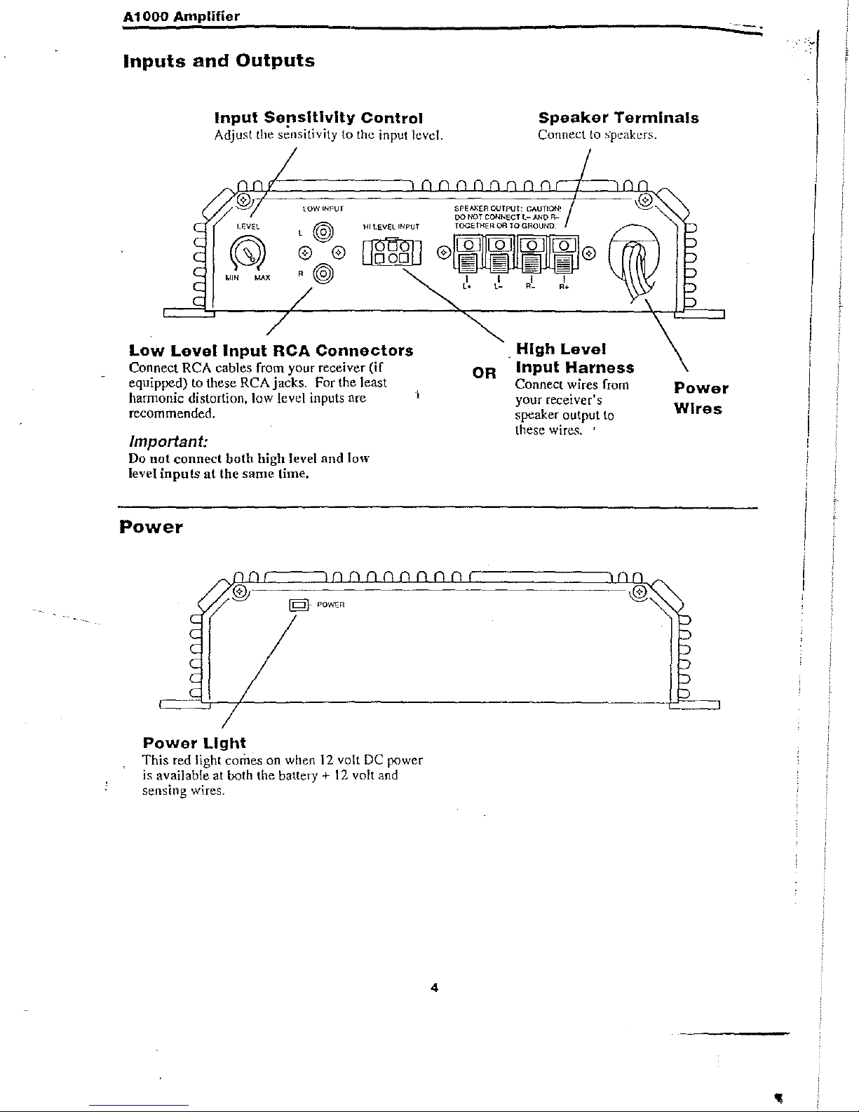
Power
§-
POWER
Power
Light
This
red light
comes
on
when
12
volt DC power
is available at both the battery
+
12
volt and
sensing wires.
OR
4
.
High
Level
Input
Harness
Connect wires from
your receiver's
speaker output
to
these
wire...;;.
'
Power
Wires
-
I
I
I
I
I
,
Page 5
A
1000
Amplifier
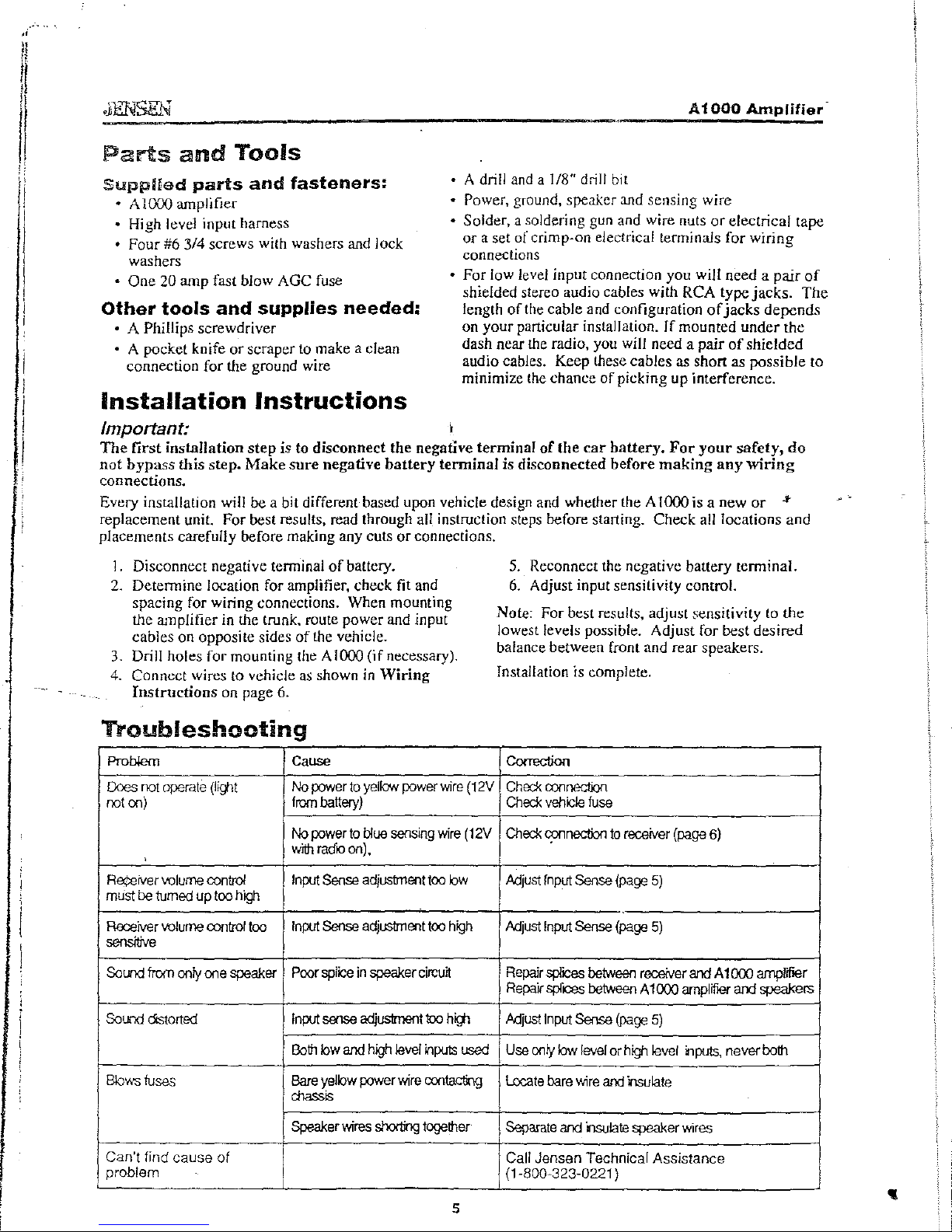
Parts
and
Tools
Supplied
parts
and
fasteners:
• A drill and a 1/8" drill bit
•
A1000
amplifier
• Power, ground, speaker and sensing wire
High level input harness
•
Four
#6 3/4
screws
with washers and lock
washers
• Solder. a soldering gun and wire nuts
Of
electrical
tape
or
a set
of
crimp-on electrical terminals
for
wiring
connections
•
One
20
amp
fast blow AGC fuse
Other
tools
and
supplies
needed:
• A Phillips screwdriver
• A pocket knife
or
scraper to make a clean
connection for the ground wire
•
For
low level input connection you will need a
pair
of
shielded stereo audio cables with RCA type
jacks.
The
length
of
the cable and configuration
of
jacks
depends
on
your
particular installation.
If
mounted
under
the
dash near the radio, you will need a
pair
of
shielded
audio cables. Keep these cables as short as
possible
to
minimize the chance
of
picking
up
interference.
Installation
Instructions
Important:
,
The
first
installation
step
is to
disconnect
the
negative
terminal
of
the
car
battery.
For
your
safety,
do
not
bypass
this
step.
Make
sure
negative
battery
terminal
is
disconnected
before
making
any
wiring
connections.
Every installation will be a bit different based
upon
vehicle design and whether the A
1000
is a
new
or
..
replacement unit. For best results, read through all instruction steps before starting.
Check
all locations
and
placements carefully before making any cuts
or
connections.
1.
Disconnect negative tenninal
of
battery.
2.
Determine
location for amplifier, check fit and
spacing for wiring connections. When mounting
the amplifier in the trunk. route power and input
cables on opposite sides
of
the vehicle.
3. Drill holes
for
mounting the A 1000
(if
necessary).
4.
Connect wires
to
vehicle
as
shown
in
Wiring
Instructions
on page 6.
Troubleshooting
Problem
Cause
Does
not
operate
(Iiglt
No
power
to
yellow
power
wire
(12V
not
on)
lrom
battery)
No
powerto
blue
sensing
wire
(12V
with
radb
on).
Re¢8iver
volume
control
Input
Sense
adjustment
too
bw
must
ba
turned
up
too
high
Receiver
volume
control
too
Input
Sense
adjustment
too
high
sensrove
Sound
from
only
one
speaker
Poor
splice
in
speaker
eireutt
Sound
distorted
Input
sense
edjustment
too
high
Both
bwand
high
level
"'puts
used
Btov,s
tuse3
Bare
yelbw
power
wire
contacting
chassis
Speaker
wires
shorting
together
Can't find cause
of
problem
5
5. Reconnect the negative battery terminal.
6.
Adjust input sensitivity control.
Note: For
best results. adjust sensitivity to
the
lowest levels possible. Adjust for
best
desired
balance between front and rear speakers.
Installation
is complete.
Co<rection
Check
oonnecOOn
Check vehde
fuse
Check
connecOOn
to
receiver
(page
6)
Mjust
Input
Sense
(page
5)
Mjust
Input
Sense
(page
5)
Repair
splices
between
receiver
and
A 1000 amplifier
Repair
splices
between
A 1000
amplifier
and
speakers
Mjust
Input
Sense
(page
5)
Use
ooly
low
level
or
high
level
inputs. never
both
Locate
bare
wire
and
insulate
Separate
and
nsuiate speaker
wires
Call Jensen Technical Assistance
(1·800~323·0221
)
Page 6
A1000
Amplifier
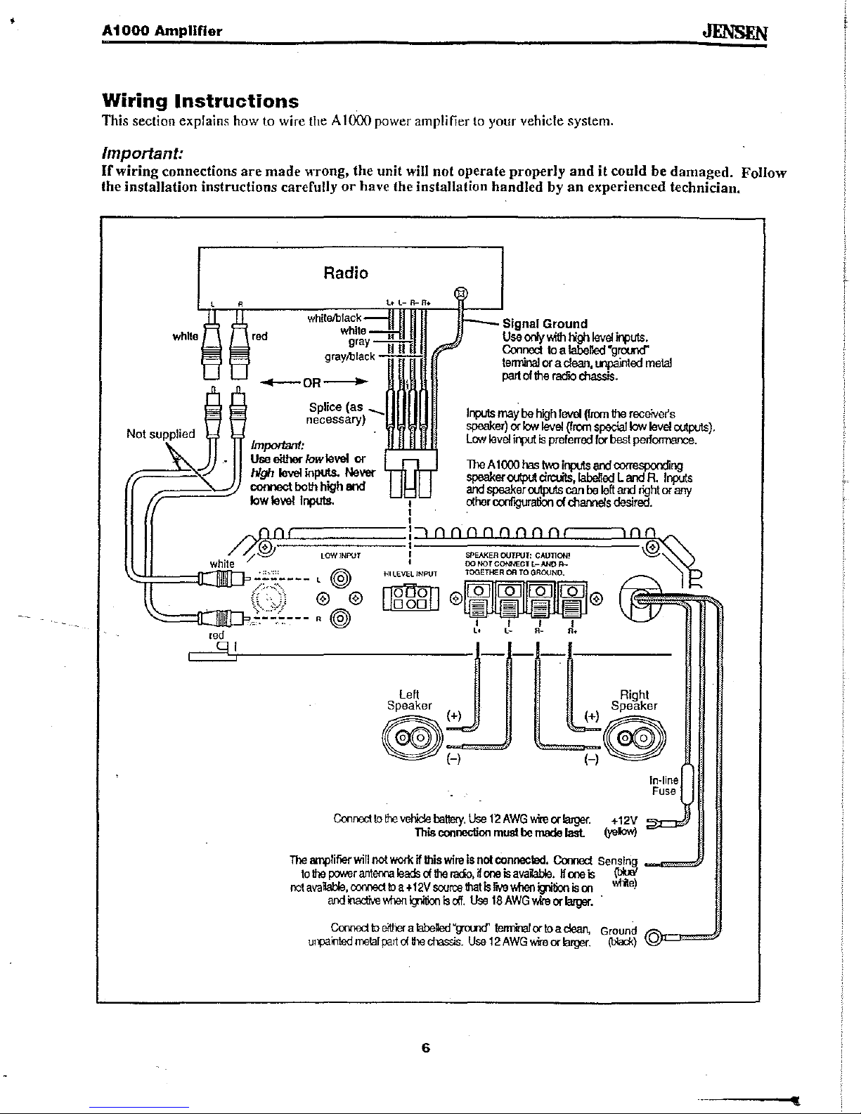
Wiring
Instructions
This section explains how to wire the A I (X){) power amplifier
to
your vehicle system.
Important:
If
wiring connections
are
made
wrong, the unit will not operate properly
and
it
could be
damaged.
Follow
the installation instructions carefully
or
have the installation handled
by
an
experienced technician.
wh1te
red
ql
Radio
Signal Ground
red
-OR-
Splice (as
""'-
necessary)
W~IWIWII
Use
00y
IWh
high
level
inputs.
Connect
10
a
labelled
"ground"
tenninal
or
a
clean,
tnpainted
metal
part
of
the
racflO
dlassis.
Inputs
may
be
high
level
Urom
the receive,s
speaker)
or
k:m
level
(Irom
special
k:m
level
outputs).
Low
level
input
is
preferred
for
best
performance.
Imporlan1:
Use
either
/owlevel
or
high
level
inputs.
Never
comect both high and
low
level
Inputs.
The
A 1
000
has
two
inputs
an:!
corresponding
speaker
output
circuits,labeIIed
l and R
Inputs
an:!
speaker outputs can
be
left
and
right
or
any
other
conflQUfation
of
channels
desired.
SPEAKER
OUTPUT:
CAUTION!
00
NOTCOt.NECT
l-ANO
f!-..
HI
lEVCl
INPUT
TOGETHER
OR
TOGROUND.
Ilg-ggll
@~@
I I I I
L.
l-
R_
R.
J
---C
left
..
• Righi
Speaker
..
....
.•..
Speaker
®
(+) •
(+)®
~
........
~
H
(-)
In-line
Fuse
Con_lo
the
vehicle
battery.
Use
12
AWG
\We
orlarger. + 12V
This
coonection
must
be
made
last
(yelow)
The
amplifier
will
not
work
if
this
wire
is
not connected.
Connect
Sensing _-==,{J
10
the
pctM9r
antema
klads
of
the
ra<io,
K
one
is
avaiWe. H one
is
(bUiI
rot
avaiable,
oonned
to
a +
12V
source
that
is
rlYB
Vwilen
igliOOn
is
00
....rite)
an:!
k1activev.l1oo
'Titian
is
off.
Use
18AWGvkeorlarger
..
Connect
10
either
a
t:IbeDed
"gomd'
tenninal
or
to
a
clean,
Ground
"):)1::3==1)
u,-"ailled
!Mlal
part
of
the
chassis.
Use
12
AWG
\We
or
larger.
(b'ad<)'
0
6
 Loading...