

Page 1

Page 2

Handbook of Instructions
FOR
THE
JENSEN
MODEL
This handbook is published for the use and
assistance of owners of JENSEN CARS. It
embodies in a concise form the advice and
suggestions of the Company's Technical Staff
in regard to lubrication, general care, and
maintenance, together with supplementary
information regarding the necessary adjustments
which may be required from time to time.
PRICE
1216
NETT
Compiled
and
Published by
JENSEN
MOTORS LTD.
WEST BROMWICH
ENGLAND
Telephones
:
W.B.
1112-2-3
Telegrams
:
"
Expert
"
PAGE
ONE
Page 3

................................................................................................................................................
Chassis No
...................................................................................................................................................
Engine No
........................................................................
Registration No
............................................
..
Original date of
delivery from Works
...........................................................
....
...........................................
PAGE
TWO
Page 4

Foreword
I
N
COMPILING THIS BOOK some knowledge
of the operation and care of a Motor Car has
been pre-supposed, and the instructions
contained herein, will, if followed with reasonable
care, enable you to obtain the maximum enjoy-
ment and satisfaction from your JENSEN Car.
Illustrations are provided to give useful
information in the simplest form, and a lubrica-
tion chart will be found on page
11.
In the rare event of any unforeseen defect or
unusual trouble developing,
it
is requested that
the matter be at once brought to our notice.
The interest of Jensen Motors Ltd. in their
productions does not end with the delivery of
the Car; on the contrary,
it
is the Company's
desire to keep in close touch with all Jensen
owners, and to provide for their convenience,
a
Service after sales second to none.
JENSEN MOTORS LIMITED
PAGE
THREE
Page 5
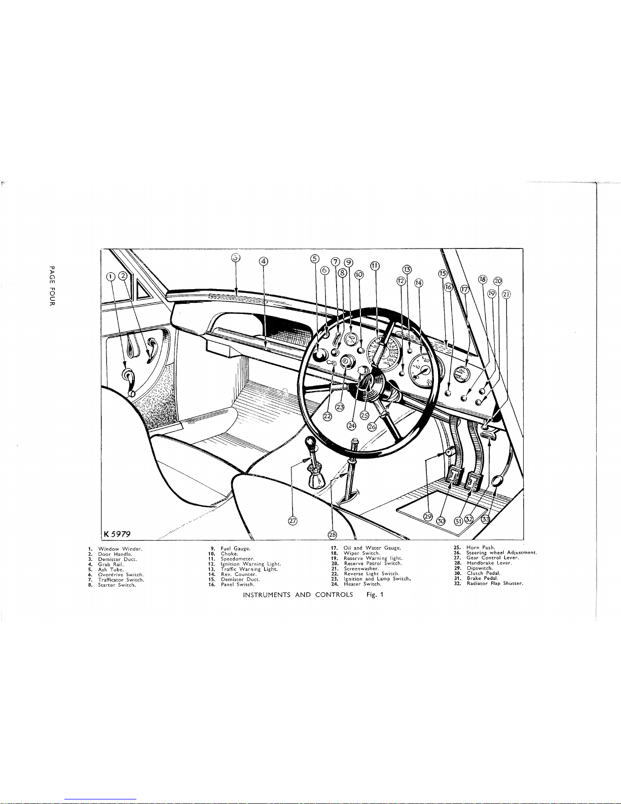
1.
Window Winder.
2.
Door Handle.
3.
Demister Duct.
4.
Grab Ra~l.
5.
Ash Tube.
6.
Overdrive Switch.
7.
Trafficator Switch.
8.
Starter Sw~tch.
9.
Fuel Gauge.
10.
Choke.
11.
Speedometer.
12.
lgnition Warning Light.
13.
Traffic Warn~ng Light.
14.
Rev. Counter.
15.
Demister Duct.
16.
Panel Switch.
17.
Oil and Water Gauge.
18.
Wiper Switch.
19.
Reserve Warning light.
20.
Reserve Petrol Switch.
21.
Screenwasher.
22.
Reverse Light Switch.
23.
Ignition and Lamp Switch.
24.
Heater Switch.
25.
Horn
Push.
26.
Steering wheel Adiustment.
27.
Gear Control Lever.
28.
Handbrake Lever.
29.
Dipswitch.
30. Clutch Pedal.
31.
Brake Pedal.
32.
Radiator Flap Shutter
INSTRUMENTS AND CONTROLS
Fig.
1
Page 6
STARTING
UP
AND GENERAL RUNNING HINTS
Treat the new car with consideration. Although every JENSEN car
is thoroughly tested on the road, the first few hundred miles should be done at a
moderate speed. We do not tie
JENSEN
owners to the monotonous observance
of an arbitrary maximum speed for a given distance, but we recommend that sustained high speeds in excess of say
60
miles per hour be avoided until the car has had
reasonable time to settle down and all moving parts are freed from their
initial stiffness. The observance of these precautions will be reflected later on in
the prolonged life of the car. Under this heading, lubrication
is
by far the most
important item. Many troubles are directly traceable to lack of proper lubrication
and owners will be well repaid by giving careful attention to the lubrication diagram
Page
11.
The engine attains maximum power at
3700
r.p.m. and
4000
r.p.m. should not
be exceeded.
We strongly recommend owners who do not wish to carry out their own oiling
and greasing to take advantage, where possible, of the facilities offered by service
stations with modern lubrication equipment.
The illustration on page four shows the general arrangement of controls and
the following points should be observed in starting the engine.
(a) Ensure that the gear control lever is in neutral.
(b) Switch on the ignition and
if
starting from cold, pull out switch on facia
marked
C.
This operates a small electric starting carburetter which feeds
a rich mixture to all the cylinders. Press starting switch firmly.
The engine
should then start immediately.
Never Race the Engine from a cold
start-this
is
most injurious.
The starting carburetter must be switched off when the engine has warmed
up. As a general guide, this will take place after
+
to
74
miles have been
covered, depending on the ambient temperature.
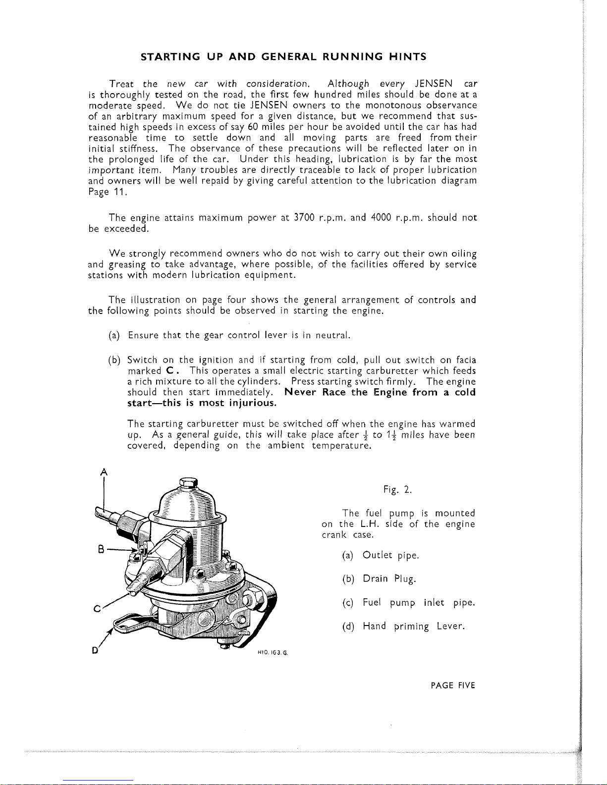
Fig.
2.
The fuel pump is mounted
on the
L.H.
side of the engine
crank case.
(a) Outlet pipe.
(b) Drain Plug.
(c) Fuel pump inlet pipe.
(d) Hand priming Lever.
PAGE
FIVE
Page 7

(c) When the car has been parked for some time or if the carburetter float
chambers have been dismantled for cleaning, fuel will have to be pumped
to the carburetter before the engine can be started. In these circumstances
operate the fuel pump hand priming lever.
(Fig.
2).
Fig.
3.
The full flow oil filter should
only be dismantled when the
filter element is to be renewed.
(a) Centre fixing bolt.
(b)
Filter casing drain plug.
(c) Filter element.
(d) Oil sump Drain plug.
The change speed arrangement being conventional,
we do not propose to describe the method of engaging
and changing gear, but we give here a plan showing the
gear lever positions.
(Fig.
4.)
Fig.
'4.
Overdrive.
The overdrive
is
an optional extra.
To engage overdrive, which can only be
operated from fourth speed position, all that
is
required
is
to pull switch on facia
marked
overdrive.
No movement of the clutch or alteration of accelerator pedal
is
necessary. Reverse process to return to fourth speed position.
PAGE
SIX
Page 8

CARE AND MAINTENANCE.
For correct lubrication of all engine parts, it is only necessary to maintain the
correct oil level in the sump.
This
is
ascertained by a Dipstick located on the right
hand side of the engine.
On all new or reconditioned engines, the sump and full flow oil filter should be
drained and refilled with new oil after the first 500, 1,000 and 2,000 miles.
After
this the operation should be repeated every 2,000 miles to provide the best running
conditions.
There
is
one drain plug in the sump and one near the bottom of the oil filter
reservoir (See (b) Fig. 3).
The capacity of the engine lubrication system is 15 pints
(8.4
litres), plus 2 pints (1.13 litres) for full flow Tecalemit Filter.
Cylinder Head Nuts
After the first 500 and 2,000 miles of running, the cylinder head nuts should be
tightened.
Tighten each nut a little at a time, working from the centre outwards.
This operation should be carried out when the engine
is
hot.
Tappets must be
checked after this operation and readjusted if necessary.
Oil Pressure.
The oil pressure gauge indicates whether the oiling system is working correctly
and
it
should be looked at occasionally while the engine
is
running.
The normal working pressure
is
55 p.s.i. and the idling pressure
is
26 p.s.i.
Should the normal oil pressure appear low, then
it
is
possible that the full flow Tecal-
emit oil filter
is
choked and in need of renewal. Never run the engine if the oil
gauge does not register pressure as serious damage may result.
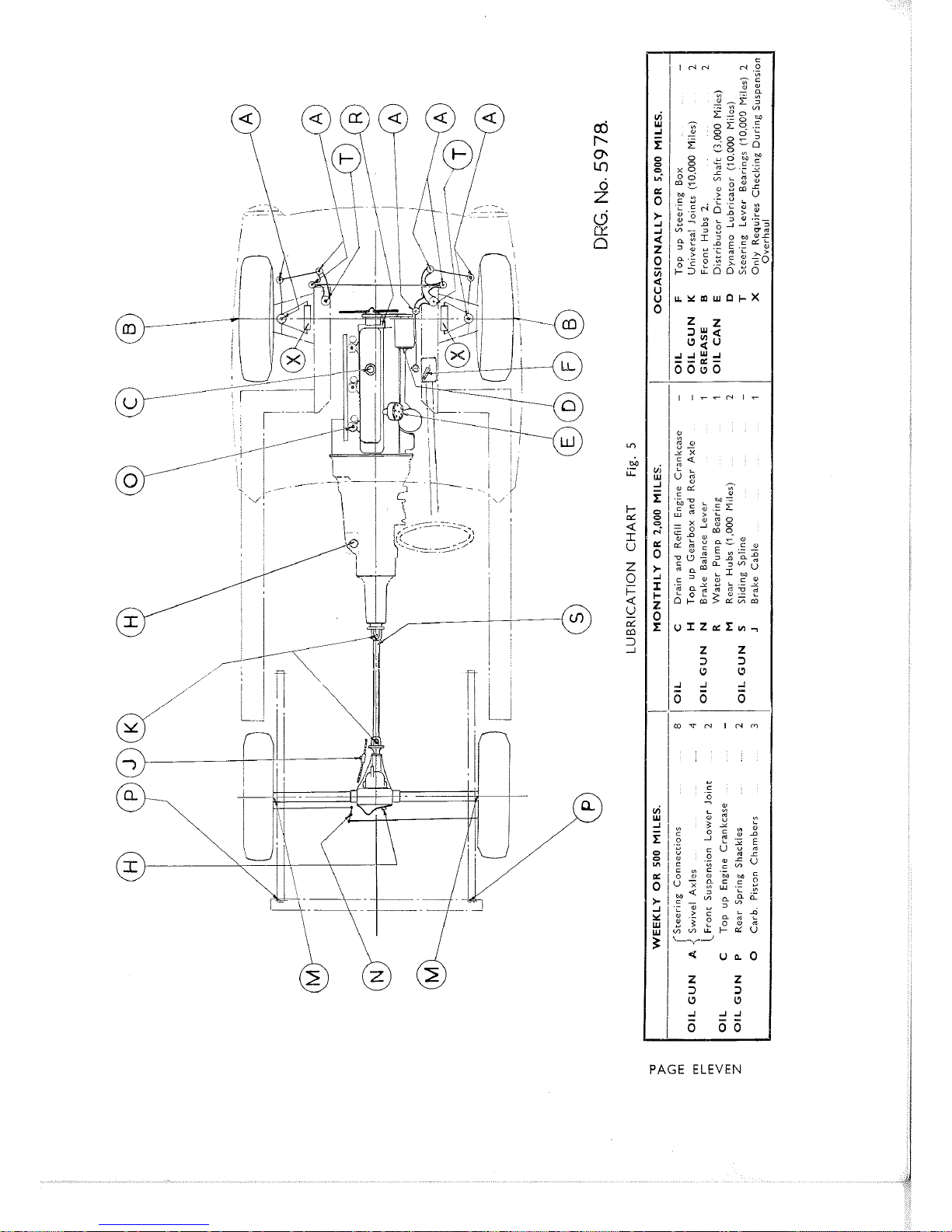
Chassis Lubrication.
The various points of the chassis should receive periodical attention as indicated
in the Lubrication Chart on Page 11.
It
is
of
vital importance
that the rear hubs
receive attention at the periods recommended, as the rear hub bearings are actually
sealed from the oil circulating in the main casing.
Rear Axle Lubrication.
The standard rear axle for this model is a Hypoid Bevel type with a ratio of
2.93
:
l.
After the first 2,000 miles, drain the rear axle and refill with a recommended
type of new oil to the level of the combined oil filler and level plug.
The oil level
should be checked every further 2,000 miles and topped up when necessary.
It is extremely important that only approved Hypoid oils be used with
this axle, without the use
of
additives
of
any kind.
Gearbox Lubrication.
Drain gearbox and refill with new oil to the top level on the dipstick after the
first 2,000 miles.
Access to the dipstick and oil filler plug is gained by lifting the
rubber plug in Tunnel.
The capacity of the gearbox is 63 pints and if Overdrive
is fitted the combined capacity of Gearbox and Overdrive
is
8
pints, the oil level on
the gearbox dipstick remaining the same. Thz oil level should be checked every
further 2,000 miles and topped up when necessary.
PAGE
SEVEN
Page 9

RECOMMENDED LUBRICANTS FOR JENSEN
'541'
WAKEFIELD
Engine Summer
......
......
......
......
Winter
......
.....
Gearbox & Overdrive
...........
......
Rear Axle (Hypoid) & Steering Box
Chassis Lubrication
&
Wheel Hubs
....
(Grease Gun.)
......
Oil Can
...... ......
......
......
VACUUM
....
Engine Summer
....
......
......
Winter
......
......
Gearbox & Overdrive
........
.....
Rear Axle (Hypoid) & Steering Box
Chassis Lubrication
&
Wheel Hubs
(Grease G
U
n
.)
...... ...... ..... ......
Oil Can
......
......
.....
....
B.P.
Engine Summer
...... ......
......
......
Winter ......
......
Gearbox & Overdrive
............
......
Rear Axle (Hypoid) & Steering Box
Chassis Lubrication
&
Wheel Hubs
(Grease Gun.)
...... ......
Oil Can
......
......
......
.....
SHELL
......
....
Engine Summer
......
......
Winter
.... .....
............
Gearbox & Overdrive
......
Rear Axle (Hypoid) & Steering Box
Chassis Lubrication
&
Wheel Hubs
......
(Grease Gun.)
......
......
......
.....
Oil Can
...... .....
......
ESSO
Engine Summer
......
......
......
......
Winter
......
......
............
Gearbox & Overdrive
......
Rear Axle (Hypoid) & Steering Box
Chassis Lubrication
&
Wheel Hubs
(Grease Gun.)
...... ...... ...... ......
Oil Can
......
......
......
......
.....
Castrol
XL.
.....
Castrolite.
......
Castrol
XL.
......
Cast rol H y poy
......
Castrolrase Heavy.
......
Castrol
XL.
.....
Mobiloil "A".
......
Mobiloil Arctic.
......
Mobiloil "A".
....
Mobilube
GX90.
......
Mobilgrease No.
4.
......
Mobiloil "A".
......
Energol SAE.
30.
......
Energol SAE.
20.
......
Energol SAE.
30.
......
Energol EP SAE.
90.
.....
Energrease
C3.
.....
Energol SAE.
30.
....
X-100 30
......
X-100 20/20W
......
X-100 30
.....
Spirax
90
EP.
......
Retinax "A"
......
X-100 30.
......
Essolube
30.
......
Essolube
20.
......
Essolube
30.
....
Esso Expee Compound
90.
....
Esso
pressure Gun grease.
Essolube
30.
.....
PAGE
EIGHT
Page 10

ADJUSTMENTS.
The engine should not require any major adjustments for at least 20,000 miles.
After this distance, should there be any falling off in efficiency,
it
may be advisable
to have the cylinder head removed for decarbonising, valve grinding and tappet
adjustment.
The correct tappet clearance
is
.012" when the valve is closed.
(Hot
or cold).
Sparking
Plugs.
Sparking plugs should be removed and cleaned in a special plug cleaning machine.
After cleaning, the points should be checked and reset if necessary to the correct
gap of .035".
The carburetters should be checked and cleaned. (See carburetter
section Page
19).
PAGE NINE
Page 11

GENERAL DIMENSIONS AND DATA FOR
QUICK
REFERENCE.
The car number will be found stamped on a plate secured to the bulkhead.
This number
is
also stamped on the top of the
L.H.
chassis frame side member im-
mediately aft of the front suspension.
The engine number is stamped on the R.H.
side of the Cylinder Block immediately below number 2 Spark Plug.
Bore
.....
......
Stroke
.....
......
......
Cubic Capacity
.....
R.A.C. Rating
Compression Ratio
...
Firing Order
Coolant Capacity
Oil Sump Capacity
Gearbox Capacity
Rear axle capacity
Fuel Tank Capacity
Overall Gear Ratios.
I
st
...... ......
9.9
:
1
2nd
......
....
6.70 : 1
3rd
......
.....
4.18 : 1
4th
...... ....
2.93
:
1
Reverse
....
12.0
Tyres
......
....
...
Tyre pressure
Wheel base
...
...
Track
......
Toe-I n
Camber
Caster Angle
K~ng
Pin
lncl~nat~on
Overall W~dth
Overall He~ght
Overall Length
Ground Clearance
Turn~ng C~rcle
Clutch Pedal
Welght (Dry)
Centre of
Grav~ty
Steer~ng ratio
87 m.m. (3.4 ins.).
111
m.m. (4.37 ins.).
3,993
C.C.
(243 cub. ins.).
28.2 H.P.
6.8
:
1 (Special Head 7.4 : I).
1, 5,
3,
6, 2, 4.
31 Pints.
15 Pints plus 2 Pints for full flow filter.
66 Pints (8 Pints with Overdrive).
3 Pints.
15 Gallons (12 Main
-
3 Reserve).
With Overdrive.
....
...
....
11.98 : 1
......
....
.....
8.14 : 1
.....
....
...
5.06 : 1
....
....
3.54 : 1
Overdrive
...
2.75
:
1
Reverse
....
14.5 : 1
Dunlop 5.50-16 (6.40~15 with wire wheels).
28 p.s.i. all round. (6.40~15-24. p.s.i.).
8
ft. 9 ins.
Front
-
4
ft.
36
ins.
Rear
-
4 ft.
34
ins.
0 ins. to ins.
1"
2
2"
6;
O
5 ft. 3 ins.
4 ft. 5 ins.
14 ft.
'10
ins.
7 ins.
34 ft.
4
ins. free movement.
26 Cwts.
49 ins. aft
cf Front axle.
16
:
1.
2; turns lock to lock.
PAGE
TEN
Page 12
INN
NO
PAGE
ELEVEN
Page 13

Ignition.
Lucas Coil and Distributor. Automatic advance and retard.
Direction of rotation
-
anti-clockwise. Contact Breaker Gap .012 ins.
Spark Plugs.
Champion N.8.B. Gap ,035 ins.
Valve Clearances.
.012 ins. hot or cold.
ELECTRICAL EQUIPMENT.
Lamp Bulbs.
....
Headlamps
......
......
Side Lamps
.....
Number Plate
..........
.........
Reverse Lamp
....
Instrument
......
......
Warning Lamps
......
Stop & Tail
......
Flashers
.... .....
Boot & Bonnet Light
60136
6w.
6w.
24w.
18 amps.
18 amps.
1816~.
24w.
6w.
Lucas No. 404.
,,
,,
989.
,,
,,
989.
P,
,,
199.
,,
,,
987.
,,
,,
987.
,, ,,
361.
,,
,,
199.
,p
,,
989.
Battery.
The Lucas 12 volt Battery Type GTWllA 64 amp. hrs. is situated below R.H.
rear seat.
This location is preferable to under Bonnet fixing as fluid evaporation
is far less rapid and consequently the "topping up" operation is less frequently
required. When the acid level falls below the top of the plates, distilled water should
be added until the plates are again covered. Keep the battery terminals clean and
tight and well smeared with petroleum jelly. This will protect the terminals from
corrosion, which if allowed to continue unchecked, will result in a break in the
battery circuit.
It is important that the battery be firmly secured in its supporting brackets at
all times.
When removing or replacing battery, remove clamp bar and bolts away
from well, otherwise bolts may be bent by the weight of the battery.
Headlamps.
Each headlamp incorporates a Lucas light unit which consists essentially of a
combined reflector and front glass assembly provided with a mounting flange by
means of which it is secured to the body housing. The bulb which is a Lucas Prefocus
type is located accurately in the reflector and is secured by a bayonet fixed
bacl<shell,
which also provides the contact to the bulb. The design of the bulb is such that
it
is correctly positioned in relation to the reflector and no focusing
is
required when
a replacement bulb is fitted.
Fig.
6.
Headlight Adjusting.
A.
C
and E are Reflector adjusting
screws, B
is
a slotted way, and D the
Bayonet catched backshell.
PAGE
TWELVE
Page 14
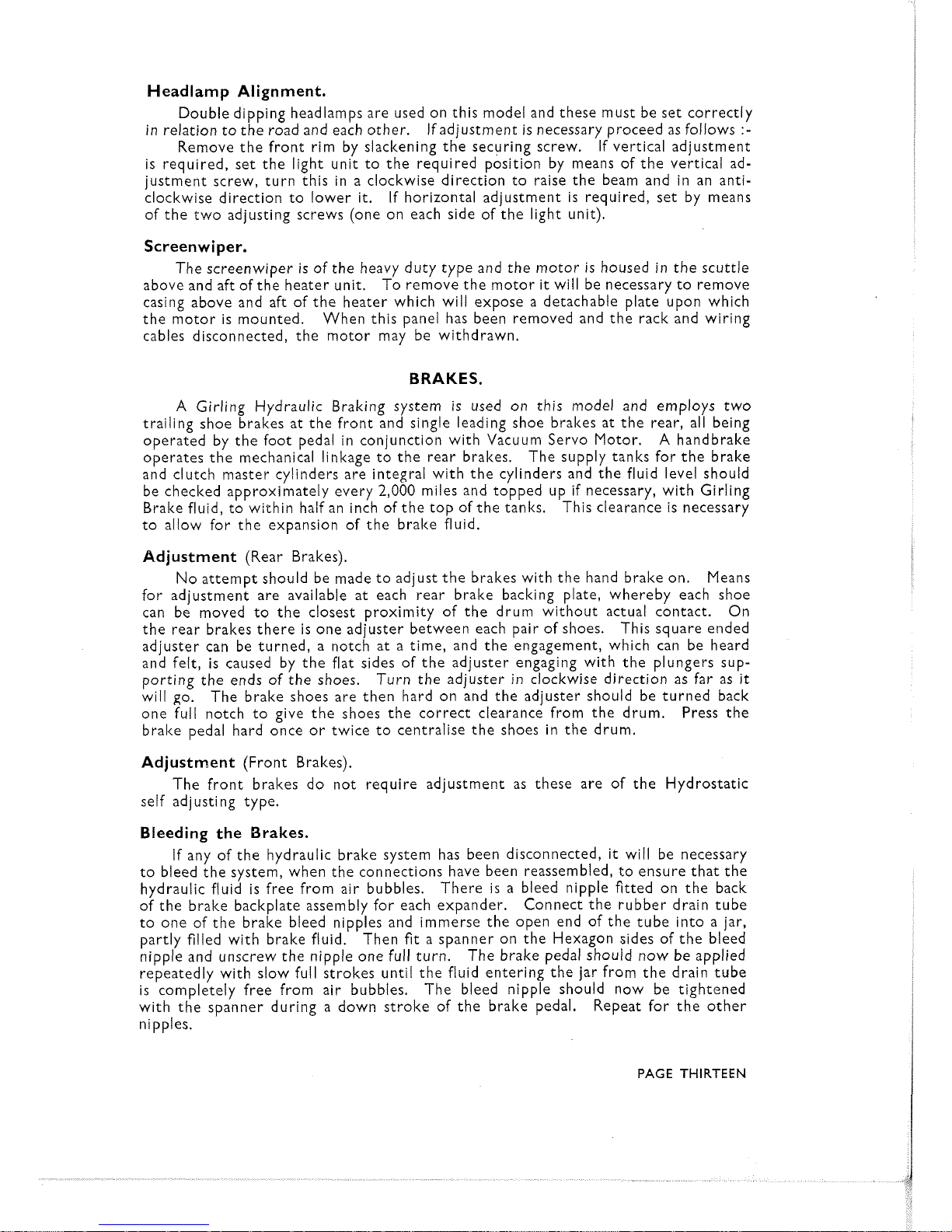
Headlamp Alignment.
Double dipping headlamps are used on this model and these must be set correctly
in relation to the road and each other.
If adjustment is necessary proceed as follows
:-
Remove the front rim by slackening the securing screw.
If vertical adjustment
is required, set the light unit to the required position by means of the vertical adjustment screw, turn this in a clockwise direction to raise the beam and in an anticlockwise direction to lower it. If horizontal adjustment is required, set by means
of the two adjusting screws (one on each side of the light unit).
Screenwiper.
The screenwiper is of the heavy duty type and the motor is housed in the scuttle
above and aft of the heater unit.
To remove the motor it will be necessary to remove
casing above and aft of the heater which will expose a detachable plate upon which
the motor is mounted. When this panel has been removed and the rack and wiring
cables disconnected, the motor may be withdrawn.
BRAKES.
A
Girling Hydraulic Braking system is used on this model and employs two
trailing shoe brakes at the front and single leading shoe brakes at the rear, all being
operated by the foot pedal in conjunction with Vacuum Servo Motor.
A
handbrake
operates the mechanical linkage to the rear brakes. The supply tanks for the brake
and clutch master cylinders are integral with the cylinders and the fluid level should
be checked approximately every
2,000
miles and topped up if necessary, with Girling
Brake fluid, to within half an inch of the top of the tanks. This clearance is necessary
to allow for the expansion of the brake fluid.
Adjustment
(Rear Brakes).
No attempt should be made to adjust the brakes with the hand brake on.
Means
for adjustment are available at each rear brake backing plate, whereby each shoe
can be moved to the closest proximity of the drum without actual contact. On
the rear brakes there is one adjuster between each pair of shoes. This square ended
adjuster can be turned, a notch at a time, and the engagement, which can be heard
and felt, is caused by the flat sides of the adjuster engaging with the plungers supporting the ends of the shoes. Turn the adjuster in clockwise direction as far as
it
will go. The brake shoes are then hard on and the adjuster should be turned back
one full notch to give the shoes the correct clearance from the drum. Press the
brake pedal hard once or twice to centralise the shoes in the drum.
Adjustment
(Front Brakes).
The front brakes do not require adjustment as these are of the Hydrostatic
self adjusting type.
Bleeding the Brakes.
If any of the hydraulic brake system has been disconnected,
it
will be necessary
to bleed the system, when the connections have been reassembled, to ensure that the
hydraulic fluid is free from air bubbles. There is a bleed nipple fitted on the back
of the brake backplate assembly for each expander. Connect the rubber drain tube
to one of the brake bleed nipples and immerse the open end of the tube into a jar,
partly filled with brake fluid. Then
fit
a spanner on the Hexagon sides of the bleed
nipple and unscrew the nipple one full turn. The brake pedal should now be applied
repeatedly with slow full strokes until the fluid entering the jar from the drain tube
is completely free from air bubbles. The bleed nipple should now be tightened
with the spanner during a down stroke of the brake pedal. Repeat for the other
nipples.
PAGE
THIRTEEN
Page 15

It
is important when bleeding the brakes to check the fluid level in the supply
tank at frequent intervals and to top up as necessary to ensure that the
master cylinders are never starved of fluid. Should air reach the master cylinders
it
will be necessary to bleed the whole system again.
Fluid which has just been bled from the system should never be used for topping
up the supply tank immediately, since it will be, to some extent, aerated. It must,
therefore, be allowed to stand for an hour or two before it can be safely used again.
Dirty fluid must be discarded since grit or other foreign matter in the system will
seriously effect braking efficiency and cause unnecessary wear.
Servs.
Under normal conditions the Servo motor should not require attention over
long periods. However, should any trouble be experienced with the Servo,
it
is
recommended that the unit be returned to the manufacturer for servicing.
(See
page
28).
Care should be taken to see that the breather pipe on the Servo unit is never
left disconnected from the breather valve situated on the front of the bulkhead in
the centre of the
R.H.
side, below the Servo.
FRONT
SUSPENSION.
The independent front suspension is of the 'Wishbone' type, the coil springs
being held in compression between the chassis frame and the lower Wishbone.
Damping is effected by telescopic hydraulic dampers (Girling BAS6). The dampers
are of the sealed type and no attention to them should be necessary. Suspension
lubrication points are shown in the lubrication chart (See Page
11).
Alignment
of
Front Wheels.
Alignment of the front wheels is an importmt factor in tyre economy and ease
of steering.
The front wheels should have a toe-in of between
0
ins. and &ins.
This measurement
is
taken between the wheel rims at the front and rear of the wheels
at a height equal to the centre of the wheel to the ground. The rear measurement
should be between
0
ins. and ins. greater than the front measurement. If the
difference between the two measurements is other than this, the wheels are out of
alignment and adjustment should be made immediately.
To carry out this adjustment, loosen the
lock nuts on the ends of the front crosstube and rotate the tube in the appropriate direction to give the correct toe-in.
To permit this adjustment the cross tube carries a right-hand thread at one end and
a left-hand thread at the other end. When the correct measurement has been
obtained, retighten the two
lock nuts. Do not alter setting of side tubes.
Adjusting Front Wheel Bearings.
If there is excessive play in the bearings, they can be adjusted as follows
:-
Jack up the front of the car and remove the nave plates and hub caps. Remove
cotter pins from bearing nuts and tighten bearing nuts with a suitable wrench. The
bearing spacer is of the non-collapsible type and provided the bearing nut
is
pulled
up tight, the correct bearing clearance will be obtained. Replace cotter pins. If
play
still
exists after tightening up the hub nuts,
it
is probable that the bearings will
need replacement.
Lubrication of Front Wheels.
Wheel bearings should be cleaned and repacked with grease every
5,000
miles
under normal conditions.
PAGE
FOURTEEN
Page 16

Centre Lock Wire Wheels.
Where centre lock wire wheels are fitted
it
is essential that the hubs, hub nuts
and inner portion of the wheel shell are kept clean and well lubricated.
Engine oil should be used for the latter purpose and not grease, particular atten-
tion being paid to the conical surfaces.
CARE
OF
TYRES.
Tyre Pressures.
The correct pressures are as follows
:-
5.50 X 16 :-28 p.s.i. all round.
6.40
x
15
:-24 p.s.i. all round.
For sustained high speed in excess of 90 miles per hour, the tyre pressures should
be increased to 34
p.s.i. all round for 5.50
x
16, and 30 p.s.i. for 6.40~ 15 tyres.
Pressures (including spare) should be checked and adjusted at least weekly.
This should be done when the tyres are cold and not when they have attained normal
running temperatures. Any unusual pressure loss should be investigated
and corrected.
Under-inflation has an adverse effect on the car and causes rapid and sometimes
irregular wear.
Also the casing may be damaged by excessive bending.
Changing Position of Tyres.
To obtain the best tyre mileage, equal wear, and to suppress the development
of irregular wear on front tyres, interchange front tyres with rear tyres at least
every 2,000 miles.
Tyre and Wheel Balance.
To provide smooth riding, precise steering and to avoid high speed steering
reaction, the tyres are balanced to predetermined limits.
By fitting the tyre so
that the white spots near the cover bead coincide with the black spots on the tube,
a high degree of balance is achieved.
If a higher degree of balance is required, the complete tyre and wheel assembly
should be balanced.
All wheel assemblies on JENSEN cars are balanced before leaving the factory
The original balance may be disturbed after a period of running.
It can be
checked, and,
if
necessary, corrected by any Service Station with tyre balance
equipment.
Factors Affecting Tyre Life.
The most important factors which have an adverse affect on tyre life are
:-
(l)
Incorrect tyre pressures.
(2)
Misalignment of wheels (See alignment of front wheels, Page 14).
(3)
High average speeds.
The rate of tread wear at 50 m.p.h. is nearly twice
as fast as at
30
m.p.h.
(4) Harsh acceleration.
(5) Frequent fierce braking.
(6) Warm dry weather.
The rate of tread wear in summer may be twice as
fast as during a cold and wet winter.
(7)
Bad road surfaces.
(8) Winding, cambered and abrasive roads.
Quite moderate speeds on such
roads will produce faster tread wear than much higher speeds on straight
flat roads.
PAGE
FIFTEEN
Page 17

TRANSMISSION.
Clutch.
The Borg and Beck loin. diameter dry, single plate clutch has a spring cushion
drive and a total frictional area of 88 sq. ins.
The clutch pedal
is
isolated from the
clutch housing by means of a flexible hydraulic control.
A
clearance of
-&
in. should
be maintained between the carbon release bearing and the pressure pad. This may
be checked by removing the
clevis pin connecting the clutch release arm and the
slave cylinder connecting arm and measuring the amount of free movement at this
connecting point.
This should be
$
in. If it is other than this, adjustment may be effected by slackening off clevis locknut and rotating clevis in the appropriate direction to obtain
the requisite free movement. When this has been obtained the pin should be re-
placed, split pinned and
clevis locknut fully tightened.
The method of bleeding is the same as that described for the brakes on Page 13.
The clutch release bearing requires no lubrication.
Gearbox.
The gearbox provides 4 speeds forward and reverse, with synchromesh 2nd,
3rd and top gears.
Ratios are as follows
:-
......
1st Gear
...........
......
3.07:l 2nd Gear
....
.....
1.88:l
......
3rd Gear
............
...
1.27:l 4th Gear
......
......
1.OO:l
Reverse
....
...... .....
3.07:l
Instructions for lubrication are given on Page
7.
The gearbox mainshaft is extended in a housing which allows the use of a short
propeller shaft and provides additional mainshaft bearings to give firmer positioning
for the gears.
Oil capacity
64
pints.
When Overdrive
is
fitted (optional extra) the combined
capacity of the gearbox and overdrive is eight pints.
Propeller Shaft.
The open propeller shaft has Hardy Spicer needle roller bearing universal joints.
Lubrication particulars for this will be found on the lubrication chart on Page 11.
Rear Axle.
The rear axle is of the semi-floating type with shim adjustment for all the
bearings and meshing of the Hypoid drive gear and pinion matched assembly.
The
axle shafts are
splined at the inner ends, which engage splines in the differential side
gears, while the outer ends have tapers and keys to
fit
the rear wheel hubs.
The hubs are supported by taper roller bearings pressed on to the axle shafts
and located in the ends of the axle tubes.
Outward thrust on either wheel is taken
by the adjacent hub bearing, whilst inward thrust is transmitted through the axle
shafts and slotted axle shaft spacer to the opposite bearing. Thus, each hub bearing
takes thrust in one direction only.
PAGE
SIXTEEN
Page 18

A
cover on the rear of the gear carrier housing permits the inspection and
flushing of the differential assembly without dismantling the axle.
The axle gear ratio is stamped on a tag attached to the assembly by one of the
rear cover screws. The axle serial number is stamped on the gear carrier housing
and should always be referred to when corresponding with reference to any
particulzr
unit.
In the event of trouble through any cause, wherever possible
it
is strongly
recommended that use should be made of the factory reconditioning service.
It should be clearly understood that the adjustment of the Hypoid Bevel axle
is more complex than that necessary for the satisfactory performance of the spiral
bevel.
For rear axle lubrication, see instructions on Page
7.
FUEL
SYSTEM.
Fuel Pump.
The fuel tank is mounted aft of the rear axle and is of 15 gallons capacity-l2
gallons main,
3
gallons reserve.
The
3
gallons reserve are not metered on the gauge.
From this tank fuel is fed to the carburetter by an A.C. mechanical pump mounted
on the
L.H.
side of the engine crank case. A priming lever is fitted to enable the
carburetter to be primed by hand (See Fig.
2,
Page 5). This should be used if the
carburetter float chamber has just been replaced after cleaning, to save an excess of
strain on the battery through using the starter to pump fuel through the system.
Approximately every 5,000 miles the strainer gauze in the fuel pump should be re-
moved and cleaned.
Fig. 7.
This exploded view of the fuel pump,
shows the location of the strainer gauze.
A. Outlet pipe union.
B.
Drain Plug.
C.
Inlet pipe union.
D.
Strainer gauze.
E.
Cork washer.
F.
Cover securing screw.
Access to the strainer is gained by removing the pump top cover and at the same
time that the strainer gauze is removed, the pump drain plug should be unscrewed
and all sediment removed from the body of the Dump chamber. Use fuel and a non-
,
a
fluffy rag for cleaning the chamber2,;nd for the strainer gauze use fuel only.
(See Fig.
7,
Page 17).
PAGE SEVENTEEN
Page 19

CARBURETTERS.
Fig.
8.
(1) Filter.
(2) Float.
(3)
Float chamber secur-
ing. nut.
(4) Float needle.
(5) Air bleed.
(6) Bridge plate screw.
(7) Fast idling screw.
(8) Stop collar.
(9)
Terminal Itnob.
(10) Solenoid Case.
(11) Solenoid.
(12) Plunger.
(1 3) Control spring.
(14)
Plunger return spring.
(15) Valve flat.
(16) Valve seat insert.
(17) Olive union nut.
(18) Taper needle.
(19) Therrno jet.
(20) Fuel passage.
(21) Holding up bolt.
(22) Banjo union bolt.
(23)
Float tickler pin.
Fig.
9.
'
(1) Cork Gland Washer.
K(2) Slow running adjustment screw.
(3)
Throttle spindle.
(4) Vacuum Ignition Union.
(5) Holding up bolt.
(6) Nut cap.
(7) Jet adjusting screw.
(8) Fibre washer.
(9) Jet lower bearing.
(10) Jet head.
(11) Brass sealing ring.
(12) Cork sealing ring.
(13) Gland spring.
(14) Main jet.
(15) Needle.
(16) Needle
loclting screw.
(17) Piston.
(18) Piston spring.
(19) Suction chamber.
(20) Oil Cap,
PAGE EIGHTEEN
Page 20

Fig.
10.
(1) Upper jet bearing.
(2) Main jet.
(3)
Cork gland washer.
(4) Fuel Passage.
(5)
Gland washer.
(6)
Brass sealing ring.
(7) Jet head.
(8)
Nut cap.
(9)
Jet adjusting screw.
(10) Fibre washer.
(1 1) Jet lower bearing.
(12) Set screw.
(13)
Cork sealing ring.
(14) Gland spring.
('i
5)
Copper plug.
(16)
Float chamber body.
(17) Copper washer.
The model
'541'
has three S.U. carburetters, with a smal! electrically operated
carburetter for starting. This starting carburetter which
is
operated by a switch
on the facia panel marked
'C,'
supplies a rich mixture to the cylinders for easystarting.
This starting carburetter must be switched off as soon as possible after the motor
has warmed up.
The carburetters are carefully synchronised to ensure perfect running for the
engine and
it
is,
therefore, very important that the throttle linkage between the
carburetters is not interfered with in any way. The carburetters will also give the
best results if adjustments are only made when absolutely necessary.
Maintenance.
The only attention normally required
is
the monthly application of a few spots
of thin machine oil to each carburetter suction chamber oil cap.
This will ensure
that the taper needle and piston assembly are free to respond readily to changes in
engine speed.
The filter in the inlet unions to each carburetter should be cleaned occasionally.
Unscrew the unions, lift off the filter, rinse in clean fuel and replace.
Ensure that
the two fibre washers are in position on each side of the union.
If the running of the engine
is
poor, always make sure that the trouble does not
lie elsewhere than the carburetters.
Check the spark plugs and distributor contact
breaker points and see that the tappets are correctly set.
PAGE
NINETEEN
Page 21

Carburetter Pistons.
Sluggish and uneven running may be caused by sticking carburetter pistons.
When the engine is thoroughly warm, remove the air cleaner and connections,
switch off the engine and then check that the carburetter pistons fall freely when
lifted and released. If any of the pistons stick, the cause may be dirt in the suction
chamber or an incorrectly centred jet. To examine a suction chamber, remove its
three securing screws and lift off the cover, when the chamber and piston can be
cleaned with a non-fluffy rag. Do not use metal polish or emery cloth. If when the
piston is replaced
it
does not fall freely,
it
is probable that the jet is not correctly
centred or the jet needle is bent. In the latter case needle should be replaced.
To centre the jet, remove the nut cap, release the large hexagon screw half a
turn or so and then screw up the jet as far as it will go, noting the number of turns.
This procedure will centre the jet on
the needle and the large hexagon screw can
now be tightened. Finally, release the jet the same numbzr of turns as were needed
to screw it up fully.
Slow Running.
When the idling setting is correct, the carburetters will operate properly at
all speeds. The two adjustments on each carburetter effecting slow running are the
throttle stop screw and the jet adjustment screw. The jet adjustment screws weaken
the mixture when screwed up and enrich
it
when screwed down. When these
screws are correctly adjusted, lifting any of the pistons with a thin blade will slow
the engine down. If the lifting of the piston makes the engine go faster, it indicates
that the carburetter setting is too rich and must therefore be weakened. At the
same time
it
may be necessary to enrich the other two carburetters until a good
balance is obtained.
Starter Carburetter.
The only adjuster is the idling hexagon screw through which the needle passes.
When the engine is hot and the starter carburetter is switched on, the screw should
be adjusted upwards as far as possible without uneven running of the engine. If
next time a cold start is attempted, the engine starts and then stops, the adjusting
screw should be released another third of a turn.
Air Cleaner.
The three cleaner elements should be removed and cleaned every
5,000
miles.
To do this remove the air cleaner by unscrewing the three bolts which secure the
cover plate and the three elements to the back plate. Immerse the elements in
petrol and wash thoroughly.
Allow to dry and then dip in clean engine oil. Shake
out any surplus oil and reassemble.
When carrying out the above operation
it
is necessary to disconnect the rubber
Servo connection. Care must be taken to prevent dirt from entering the system
whilst the pipe is disconnected.
PAGE
TWENTY
Page 22

ENGINE.
Dimensions.
Bore
87
m.m. (3.43 ins.).
Stroke 111 m.m. (4.375 ins.).
Capacity 3993
C.C.
(243 cub ins.).
R.A.C. rating 28.2 h.p.
Compression ratio 6.8
:
1 (Standard) 7.4 : 1 (Special Head).
Cylinders.
Six cylinders, integral with crankcase. Special cast iron is used and there are
full length water jackets. The detachable cast iron cylinder head carries the valve
gear.
Maximum Rebore.
The maximum permissible rebore
is
bore diameter plus .040 ins.
Crankshaft.
The forged steel counterbalanced crankshaft has a torsional vibration damper
and
is
supported by four detachable "Thinwall" bearings.
Crankshaft Regrinding Sizes.
Undersize
CRANKPINS JOURNALS
Bearing
--p----
Minimum Maximum Minimum Maximum
-
----
---
.020 in.
2.1
048 in. 2.1053 in.
2.4590 in. 2.4594 in.
.040 in.
2.0848 in. 2.0853 in. 2.4390 in. 2.439; in.
1
Connecting Rods.
The connecting rods are of forged steel with detachable "Thinwall" bearings.
Pistons.
Aluminium alloy with Anodised surface.
Split skirt type with threecompression
rings and one scraper.
Piston Fitting.
.0012 ins, at top to .0018 at skirt.
Piston Rings.
Gap - .021 ins. to ,015 ins.
Groove width.
Compression
.0957 ins. to .0967 ins
Oil Control .l58 to .l59 ins.
Groove clearances
-
Compression .0017 to .0037.
Camshaft.
The forged steel camshaft is supported by four "Thinwall" bearings and driven
by a duplex roller chain.
A synthetic rubber tensioner ring for the timing chain,
and
a
sound insulated timing gear cover combine to ensure quiet operation.
Valves.
Heat and corrosion resisting steel is used for the exhaust valves and silicon
chrome steel for the inlet valves, while twin exhaust down-pipes permit the unrestricted escape of the exhaust gases from the cylinders.
PAGE TWENTY-ONE
Page 23

Valve Timing.
Both the camshaft gear and the crankshaft gear are spot marked for valvesetting;
the inlet valve opens at
5"
B.T.D.C.
Ignition.
Ignition coil with automatic advance and retard assisted by vacuum control.
Ignition Timing.
In order to reset the ignition timing, remove all spark plugs except that from
No.
1
cylinder and using the starting handle rotate the engine until No. 1 piston
is at T.D.C. before firing stroke. The compression felt at the handle will denote
the correct stroke. T.D.C. of No.
1
piston is marked on the flywheel
(116).
Set Micrometer adjustment to zero.
Remove the distributor cap and slacken pinch bolt of the distributor clamp.
Turn distributor casing until the contact breaker points just begin to open,
with the rotor arm pointing to the relative position of No.
1
cylinder electrode
in the distributor cap. The spark is then correctiy timed.
Finally, retighten the pinch bolt in the clamping plate and refit the distributor cap.
Finer adjustment can be obtained under road conditions by means of
the micrometer adjustment.
Lubrication.
A
pressure gear pump forces oil from a fin cooled cast aluminium sump to all
main, big end and camshaft bearings.
Each main bearing oil feed is supplied from a
circular channel cut in the bearing housing which provides a uniform feed of oil
between the bearing surfaces.
Big end bearing lubrication, controlled by a special oil feed in the crankshaft
also provides for jet lubrication of the cylinder walls, while oil from the camshaft
front bearing
is
guided by deflectors fitted to the camshaft gear on the timing chain.
The valve rocker shaft
is
fed by oil on the camshaft rear centre bearing.
Oil
capacity
15
pints plus 2 pints for full flow Tecalemit filter.
COOLING
SYSTEM.
Cooling.
Circulation of the coolant is by a large outlet centrifugal pump with athermostat
to assist rapid warming from cold.
The system is pressurised
andda spring loaded flap is provided to give further
control, should this be necessary. "The flap control is situated above the brake
pedal and should be used in
conjuoction with the coolant thermometer. To close
the flap, it is necessary to pull the control handle and vice versa. Capacity of the
cooling system
is
31
pints.
Topping Up.
Coolant level should be checked weekly.
Top up when necessary to replace
coolant lost through evaporation. Use only rainwater, if available, and
fill
to approximately 4 in. below the top of the header tank when engine is cold.
PAGE
TWENTY-TWO
Page 24

Winter Precautions.
In winter, an anti-freezing mixture should be added to the cooling water as a
safeguard against freezing and damage to the cylinder block or the radiator.
Care-
fully follow the maker's instructions when preparing the mixture, and when topping
up
it
will be necessary to maintain this mixture.
A satisfactory anti-freezing mixture
is
Smiths "Bluecol", and in this case the
correct mixture for the coolant is
20%
Bluecol and
80%
water.
Bluecol does not evaporate and provided there are no leaks in the cooling system
it
is
only necessary to top up with water.
The boiling point of this solution is
103"
centigrade.
Before adding the anti-freeze mixture it is always advisable to check the security
of the hose connection between the engine and the radiator and other water joints.
Anti-freeze %as a very searching action and soon reveals any joint weaknesses
which unless remedied will give rise to a serious loss of coolant.
When anti-freeze has been added
it
is
a good plan to tie an anti-freeze label to
the radiator drain tap to prevent a garage employee from inadvertently draining the
solution.
If
anti-freeze is not used and no other precaution is taken, the.water should be
drained off completely when garaging the car at night during frosty weather.
There are two drain taps ; one
is
at the bottom of the radiator and one
on the engine crankcase forward of the distributor.
When all the water has been drained the engine should be run for not more
than one minute at tick-over speed to ensure complete elimination of water from
the cyiina'er block.
It is advisable occasionally to clean out the tap apertures with a strong piece of
wire since the drain taps may become choked with sediment which will prevent
effective draining.
When the system has been drained it is
a
good plan to leave the radiator filler
cap on the driving seat as a reminder to refill the cooling system before using the
car again.
Flushing.
To ensure eficient circulation of the coolant and to reduce formation of chemical
deposits within the cooling passages, the system should be thoroughly flushed with
clean running water every
5,000
miles.
Cabin Cooling.
Sliding doors are provided on each side of the scuttle to permit cool air
to
be
admitted to the car interior.
Where temperature control unit (optional extra)
is fitted, please refer to Page
29
for instructions.
PAGE
TWENTY-THREE
Page 25

PAGE
TWENTY-FOUR
Page 26

ENGINE
IGNITION
MISFIRES.
-High tension leads to spark
plugs shorting.
-Incorrect spacing of sparlc
plug points.
-Cracked sparlc plug porcelain.
-Battery Connection loose.
--
Faulty or damp cap.
ENGINE STARTS
AND STOPS.
IGNITION
CARBURETTER
Water in Carburetter.
-Petrol line partly cholted.
-Fuel pump pressure low.
-Fuel pump filter cholted.
-Needle valve faulty or dirty.
LOW tension connection loose.
-Faulty switch contact.
-Dirty contact points.
MECHANICAL
-Valves sticking.
Valves burnt or
broken.
-Valve spring broken
Incorrect valve
clearance.
__
I
-
I
CARBURETTOR.
-Petrol line blocked.
-Water in petrol.
---Needle valve sticlting.
-Fuel pump faulty.
--Petrol exhausted.
--Air
lealts.
ENGINE RUNS ON WIDE
THROTTLE ONLY.
I
CARBURETTER
MECHANICAL.
1
-Slow running adjusting screw
--Valve sticking.
incorrectly adjusted.
IZvalve burnt or broken.
Valve spring broken.
--P---------------
MECHANICAL and IGNITION
ENGINE DOES NOT GIVE
CARBURETTER
FULL POWER.
-Ignition retarded.
--Timing too far advanced.
--Excessive carbon deposit.
C
Loose bearing or pistons.
2
I---
+
;<
--
High tension lead shorting.
--Valve burnt or bad seating.
--Incorrect valve clearance.
--Plug leads crossed.
--
Faulty cap.
--Petrol supply faulty.
.
..
-
-Petrol feed faulty.
--Inlet valve not closing.
-Ignition timing incorrect.
-Carburetter flooding.
ENGINE RUNS
-I
IMPERFECTLY.
,-Weak mixture. ENGINE KNOCKS.
9
-Air leaks in induction pipe.
-Jet partly choked.
Page 27

STEERING.
The cam gear steering box has a ratio of
l6:l
and has provision for taking up wear.
The height of the wheel is adjustable so that the driver may obtain the most
comfortable position. Immediately below the wheel boss there is a knurled nut.
To raise or lower the steering wheel
it
is necessary to release this nut - slide the
wheel into the required position and lock knurled nut.
The oil filler cap should occasionally be removed and the oil level inspected.
It is important that the oil level should be maintained at approximately +in. from
the top of the filler tube.
Fan Belt Adjustment.
The fan belt must be sufficiently tight to prevent slip at the Dynamo and Water
Pump, yet there should be sufficient slack to move the centre of the belt sideways
about lin.
Fig.
11.
Dynamo adjustment.
Slacken at 'A' and swing up Dynamo to
tighten the fan belt.
H.25.
162.A.
To make any necessary adjustments, slacken the bolts and raise or lower the
Dynamo until the desired tension of the belt is obtained, then securely lock the
Dynamo in position again.
BODYWORK.
Dust on the car may be lightly flicked off with a duster, but on all other occasions
the car must thoroughly washed and dried before a cellulose polish is used.
Any
attempt to rub dirt off the car will result in a severe scratching of the smooth surface
of the cellulose.
Grease and tar splashes must be very carefully removed with a soft rag dipped
in petrol.
Washing and Polishing.
When washing the car, commence from the top and worlc downwards, using
a slow flood of water and then leather off all the surplus moisture.
After washing
and drying, use a good quality cellulose polish which will not only impart a brilliant
lustre to the surface of the cellulose but will help to preserve it from atmospheric
corrosion. An occasional application of a good class wax polish will also help considerably in maintaining a smooth finish.
PAGE
TWENTY-SIX
Page 28

Seats.
Both the front and rear seats are upholstered in best quality hide and will not
require any attention other than an occacional clean down with a cloth moistened
in water.
Chromium.
Wash chromium plating with soap and warm water. On no account use metal
polish.
Other attentions.
Door locks, hinges and other small working parts should be given a drop of
oil occasionally and be checked for security.
Sliding seat runners will benefit if
periodically smeared with grease.
Front Seat Adjustment.
Provision is made for 'fore and aft' adjustment of the front seats. Adjustment
is effected by pushing the control lever, located beneath the seat in a left handed
direction, easing the seat backward or forward as required. To ensure that the
seat is properly located, check that the trigger on the adjustment lever is located in
one of the adjustment apertures.
Spare Wheel Valve.
Access to spare wheel valve is obtained through hole in rear of boot floor
TOOL
KIT.
The following tool kit is supplied with the car
:-
+
in.
\c
&
in Whitworth
DIE
Spanner.
&
in.
,;
5
in.
g
in.
\*
in,
in.
X
$
in. Whitworth Box Spanner.
&in.
X
gin,
in.
X
4
in.
Tommy Bar.
Screw Driver.
Combination pliers.
4
in. Adjustable spanner.
Wheel brace.
Starting handle and bracket.
Bevelift Jack.
Tool Wrap.
Combination hammer is supplied when wire wheels are fitted.
N.B. When it is necessary to use the starting handle the bracket supplied
must be attached to the front bumper by means of the two innermost
bumper stud nuts.
PAGE
TWENTY-SEVEN
Page 29

EQUIPMENT.
JENSEN MOTORS LTD., accept no liability for tyres, instruments, electrical
equipment and any other accessories fitted to the car which are not of their manufacture. All claims relating to any of these parts, or orders for repair to them should
be addressed to their respective manufacturers from whom further information
may be obtained on application to the addresses quoted below.
Important.
When claims are being made under guarantee it is essential to quote the car
number which
is
stamped on a plate located under the bonnet on the side of the
scuttle and the date on which the car was commissioned.
Brakes and Dampers.
Messrs. Girling Ltd., Kings Road, Tyseley, Birmingham 11.
Brake Servo System.
Messrs. Clayton Dewandre Co. Ltd., Titanic Works, Lincoln.
Electrical Equipment.
Joseph Lucas (Electrical) Ltd., Great Hampton Street, Birmingham 18, and
Dordrecht Road, Acton Vale, London, W.3.
Engine Oil Filter.
Tecalemit Limited, Great West Road, Brentford, Middlesex.
Instruments.
S.
Smith & Sons (M.A.) Ltd., Cricklewood Works, London, N.W.2.
Tyres.
Dunlop Rubber Co. Ltd., Fort Dunlop, Birmingham, and
1, Albany Street, London, N.W.1.
Tools.
Abingdon King Dick Ltd., Abingdon Works, Kings Road, Tyseley, Birmingham 11.
Lift Jack.
Smiths Jacking Systems Ltd., Jackall Works, Edgware Road, London,
N.W.2.
Door Handles and Keys.
Willmot Breeden Ltd., Eastern Works, Camden Street, Birmingham 1.
Carburetters.
S.U. Carburetters Ltd., Erdington, Birmingham.
Air Filters and Exhaust Silencers.
Burgess Products Co. Ltd., Brookfield Road, Hinckley, Leics.
PAGE
TWENTY-EIGHT
Page 30

OPTIONAL EQUIPMENT.
Overdrive.
Special head and twin exhaust system.
Rev. Counter
Screenwasher.
Heater
15 in. Centre lock wire wheels with Dunlop road speed tyres 6.40~15.
Dunlop Road Speed tyres 5.50~16 on standard wheels.
AI-fin Drums.
CAB1
N
HEATER
(Optional
Extra).
The Smiths heater and defroster unit is of 3 kilowatts nominal output. This
unit utilises waste heat from the engine and
is
located under the facia on the L.H.
side of the car.
A resistance is fitted in the heater which
is
controlled by a 3 position switch on
the facia.
First pull of switch gives
3
speed, second pull and turn gives full speed,
at which maximum heat
is
obtained.
The heater unit draws fresh air from outside the car and this may be cut off by
closing sliding door on L.H. side of bulkhead.
Hot air is ducted from the heater to
the Drivers side of the car and
is
controlled by opening a door underneath the facia.
A
similar door is fitted to the heater unit itself which when open will permit hot air
to be directed into the vicinity of the passengers feet.
At speeds above
30
miles per hour the motor
is
not necessary owing to the ram
effect in the air intake.
In summer it
is
usually desirable to turn off the cylinder head valve to permit
the heating system to be used for the circulation of fresh unheated air throughout
the car interior. This valve is located
on
the right hand side of the cylinder head
and must be screwed fully home in a clockwise direction to shut off the supply of
water to the heater radiator.
PAGE
TWENTY-NINE
Page 31

Page
BODYWORK
Washing & Polrshrng 26
Seats 27
Chromrum 27
Other attentrons 27
Front seat
adlustment 27
BRAKES
Adjustment (Rear Brakes) 13
Adjustment (Front Braltes) 13
Bleeding the Brakes
Servo.
CARBURETTERS
Maintenance
Carburetter Pistons
Slow running
Starter Carburetter
CLUTCH
CONTROLS
COOLING SYSTEM
Topping up
Winter Precautrons
Flushing
Page
FRONT SUSPENSION
Alrgnment of front wheels 14
Adjusting front wheel bearings 14
Lubrication of front wheels 14
FUEL SYSTEM
Fuel pump 17
Carburetters
18-1
9
Maintenance 19
Carburetter Prstons 20
13
14
GEARBOX
HEATER
19
20
IGNITION
20
20
Spark Plugs
Valve Clearances
l6
INSTRUMENTS
LUBRICATION
Chart
Chassrs Lubr~catron
22 Rear Axle
,,
23 Gearbox
,,
23 Front Wheels
,,
Engrne Lubrication
ELECTRICAL EQUIPMENT
Lamp Bulbs 12
Battery 12
Headlamps 12
Headlamp Alignment 13
Screenwrper 13
ENGINE
Dimensrons 21
Cylinders 21
Crankshaft
21
Crankshaft regrrnding srzes 21
Connectrng rods 21
Pistons 21
Prston Rings 21
Camshaft 21
Valves 21
Valve
tlmrng 22
lgnrtron trming 22
Lubrrcatton 22
EQUIPMENT
..
28
FAN BELT ADJUSTMENT
.
.
26
FOREWORD
......
...
3
MAINTENANCE
7
OPTIONAL EQUIPMENT
29
REAR AXLE
16
STARTING, UP AND GENERAL
RUNNING HINTS
5
SPECIFICATION
l0
STEERING
26
TRANSMISSION
Clutch 16
Gearbox
..
.. .
16
Propeller shaft 16
Rear Axle 16
TYRES
Tyre Pressures 15
Changing posltlon of tyres 15
Tyre and wheel balance 15
Factors
affect~ng tyre l~fe 15
PAGE THIRTY
Page 32

JENSEN
'6541
"
SALOQN
CARS
(a
955)
HOME
AND
EXPORT
MODELS
xrnoi
REmbE
SWTCd
6
WARNlhYj
LIGHT
SWITCH
3H
-
---
COLOURS
i
iiiG
with
RED
rf
BLUE wlth YELLOW
4
BLUE with WHITE
S
BLUE with GREEN
6
BLUE with PURPLE
7
BLUE with BROWN
8
BLUE wlth BLACK
O
WHITF
25
YELLOW
26
YELLOW
wkh
RED
27
YELLOW
with BLUE
28
YELLOW with WHITE
29
YELLOW with GREEN
30
YELLOW wlth PURPLE
31 YELLOW wlth BROWN
32
YELLOW with BLACK
33
RROWN
49
PURPLE
50
PURPLE 4th
RED
38
BROWN
wlth
GREEN
39 BROWN with PURPLE
40
SROWN
with
RI
ArK
51
PURPLE
ki;h
YKLOW
52
PURPLE with BLUE
27
PI
IRPI
C
vrirh
WUlTC
ISSUED
:
i
355
L
MARCH
1955
NUMBERS INDICATE CABLE IDENJlFlCATlON COLOURS,
SEE
KEY
ABOVE
COPYRIG
HT
All
rights reserved.
No part
of
this
diagram
may
be
reproduced without permission.
Printed
in
Enpland
 Loading...