

Jenn-Air JGR8885RDP Installation Instruction

INSTALLER: LEAVE THESE INSTRUCTIONS WITH THE APPLIANCE
INSTALLATION MANUAL
Gas 30-inch Wide Free-Standing Range
PLEASE KEEP THIS MANUAL FOR FUTURE REFERENCE
THE MANUAL IS INTENDED TO ASSIST IN THE INITIAL INSTALLATION AND ADJUSTMENTS OF THE RANGE.
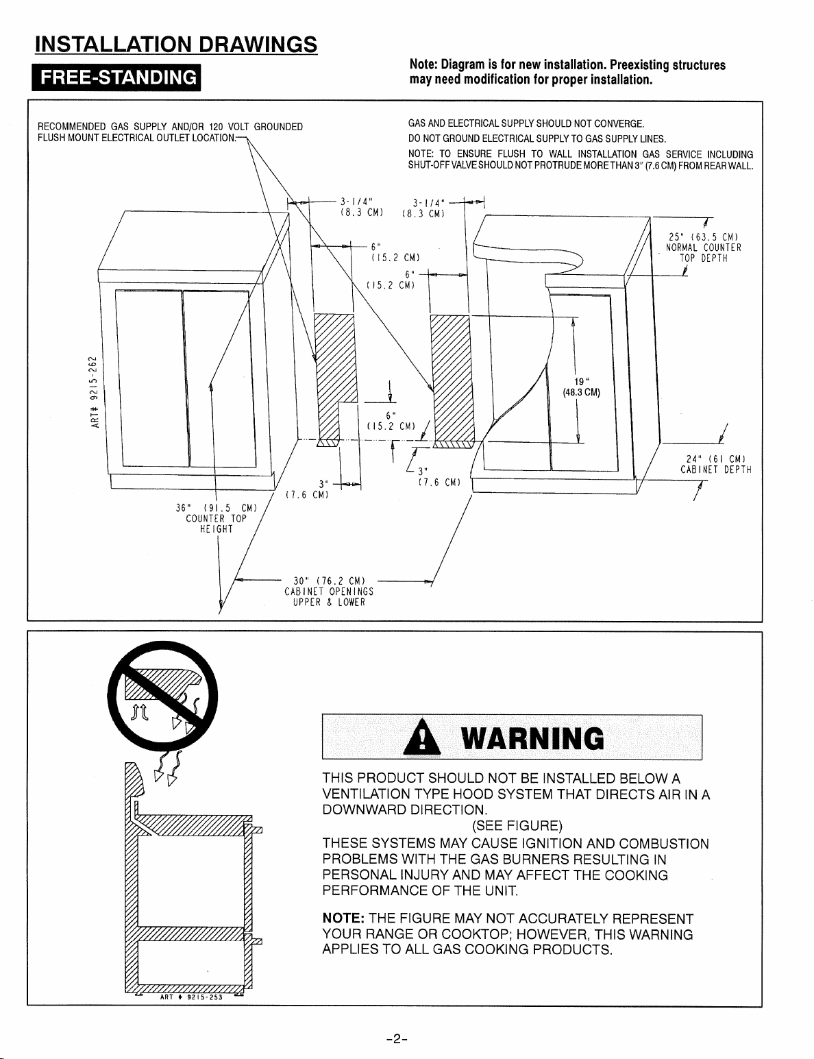
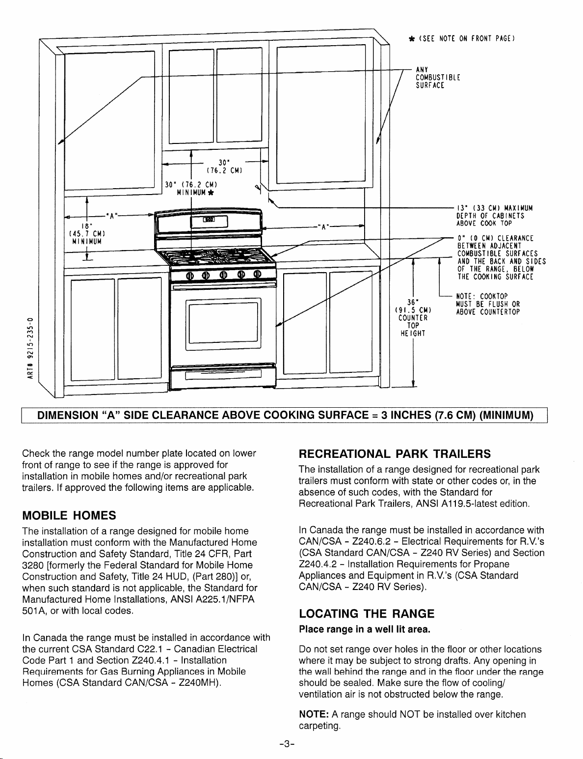
CLEARANCE DIMENSIONS
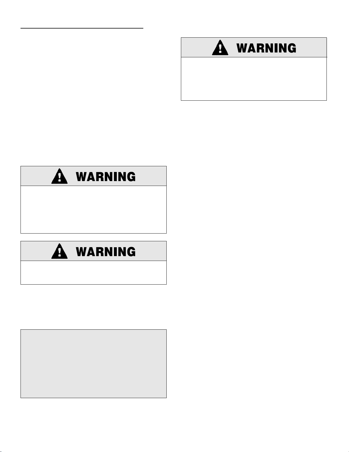
SPECIAL WARNING
Only qualified personnel should
install or service this range.
Read “Safety Instructions” in the
Use & Care book before using
range.
Range may be installed with zero inches clearance
adjacent to (against) combustible construction at the rear
and on the sides below the cooktop. For complete
information in regard to the installation of wall cabinets
above the range and clearances to combustible wall
above the cooking top see the installation drawings. For
SAFETY CONSIDERATIONS do not install a range in any
combustible cabinetry which is not in accord with the
installation drawings.
Improper installation, adjustment,
alteration, service, maintenance or
use of range can result in serious
injury or property damage.
• ALL RANGES CAN TIP AND
CAUSE INJURIES TO PERSONS.
• INSTALL ANTI-TIP DEVICES
PACKED WITH RANGE.
• FOLLOW ALL INSTALLATION
INSTRUCTIONS.
Your range may not be equipped with
some of the features referred to in this
manual.
* NOTE: The 30 inch (76.2 cm) dimension may be
reduced to not less than 24 inches (61 cm) when the wall
cabinets in a domestic home are protected with fireproof
materials in accordance with American National
Standards -- National Fuel Gas Code or in mobile homes
when they are protected with fireproof materials in
accordance with the Federal Standard for Mobile Home
Construction and Safety.
To eliminate the risk of burns or fire by reaching over
heated surface units, cabinet storage space located
above the surface units should be avoided. If cabinet
storage is to be provided, the risk can be reduced by
installing a range hood that projects horizontally a
minimum of 5 inches (13 cm) beyond the bottom of the
cabinets.
CAUTION: This range has been designed in
accordance with the requirements of various safety
agencies and complies with the maximum allowable
wood cabinet temperatures of 194°F. If this range is
installed with cabinets that have a lower working
temperature than 194°F, discoloration, delamination
or melting may occur. Contact Customer Service
for associated cabinet dimensions and installation
accessories.
8101P571-60
(02-06-02)
ANTI-TIP DEVICE INSTALLATION INSTRUCTIONS
NOTE: A risk of range tip over exists if the appliance is
not installed in accordance with the installation
instructions provided. The proper use of this device
minimizes the risk of TIP-OVER. In using this device the
consumer must still observe the safety precautions as
stated in the USE and CARE MANUAL and avoid using
the oven door and/or lower drawer as a step stool.
Installation instructions are provided for wood and cement
in either floor or wall. Any other type of construction may
require special installation techniques as deemed
necessary to provide adequate fastening of the ANTI-TIP
bracket to the floor or wall.
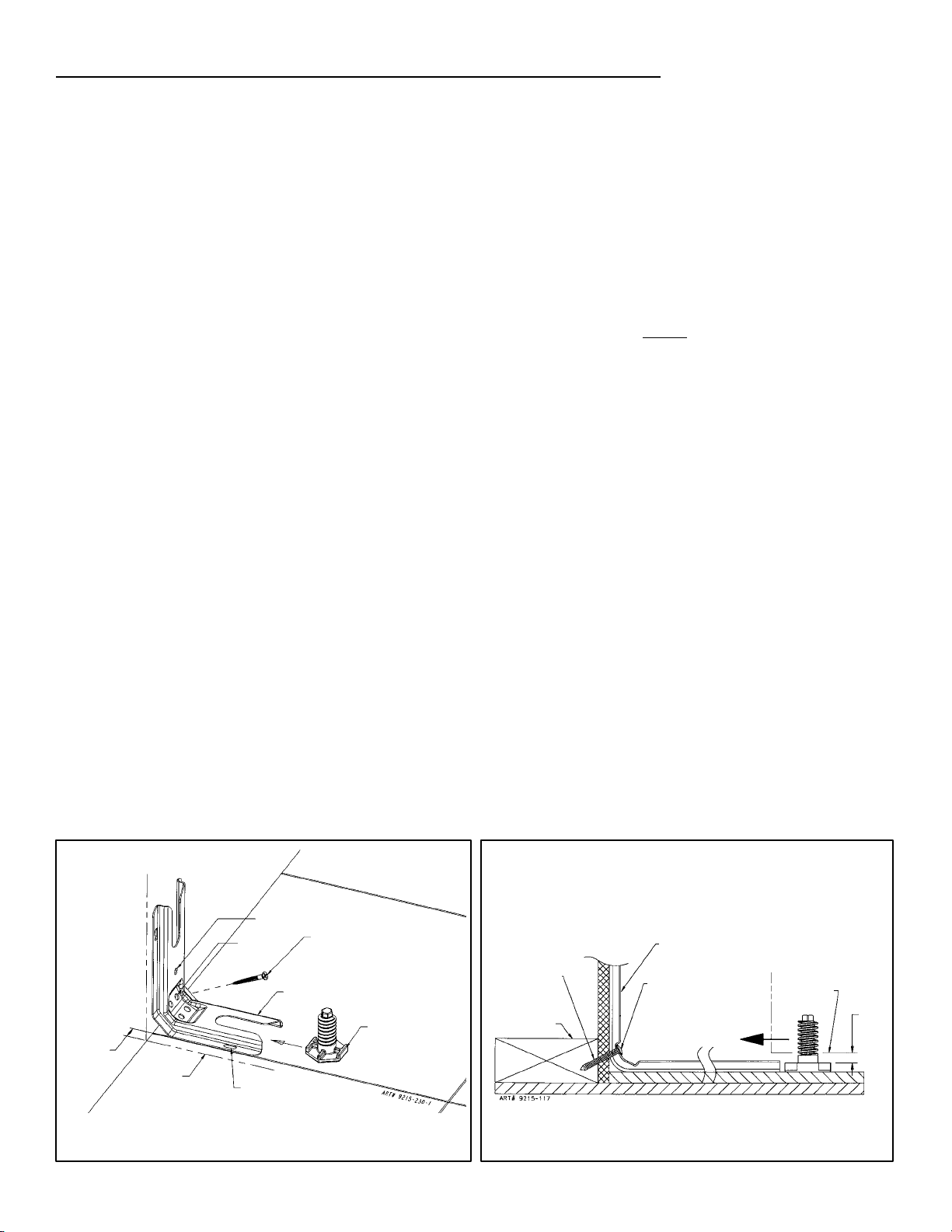
STEP 1 -- Locating The Bracket (see figure 1)
A. Determine where either the right or left rear “edge” of
the range will be located and mark the floor or wall.
B. Place the BRACKET 9/16″ (14.5 mm) from the
marked “EDGE” toward center of opening and against
the back wall as shown in figure 1, with orientation
hole against wall.
C. Use the bracket as a template and mark the required
holes, as shown in figure 1 for the type of construction
you will be using.
STEP 2 -- Anti-Tip Bracket Installation
A. Wood Construction:
1. Floor: Locate the center of the two holes identified
in figure 1 as “HOLES FOR FLOOR”. Drill a 1/8″
(3 mm) pilot hole in the center of each hole (a nail
or awl may be used if a drill is not available).
Secure the ANTI-TIP bracket to the floor with the
two screws provided. Proceed to STEP 3.
2. Wall: Locate the center of the two holes identified
in figure 1 as “HOLES FOR WALL. Drill an angled
1/8″ (3 mm) pilot hole in the center of each hole
as shown in figure 2. (A nail or awl may be used if
a drill is not available). Secure the ANTI-TIP
bracket to the wall with the two screws provided
as shown in figure 2. Proceed to STEP 3.
B. Cement or Concrete Construction:
1. Suitable screws for concrete construction can be
obtained at a hardware store. Drill the required
size hole for the screws obtained into the
concrete at the center of the holes identified in
figure 1 as “HOLES FOR FLOOR”. Secure the
ANTI-TIP bracket to the floor. Proceed to STEP 3.
STEP 3 -- Range Installation
A. For safety considerations as well as optimum
performance, adjust the range so it is level and to
desired height prior to installing in cabinet opening.
NOTE: Cooktop MUST
be flush or above
countertop.
Levelness may be checked by placing a spirit level or
a large pan of water on the cooktop or oven rack.
Adjust the range by tipping it forward or back and
rotate the leveling feet as required.
NOTE: A minimum clearance of 1/4″ (6 mm) is
required between the range and the leveling foot that
will engage the anti-tip bracket, (see figure 2).
CAUTION: Damage to the range may occur if range
is moved or lifted by grasping the main top, backguard
or door handles.
B. Align the range to its designated location and prepare
to slide it back into position. Connect gas line and
plug in power cord to outlet following guidelines
outlined in connecting the range and remainder of
installation instructions.
C. Slide range in place visually inspecting to verify that
power cord and gas line are freely routed and
contained within recessed area of back panel.
D. To check the range for proper installation of the
anti-tip bracket, use a flashlight and look underneath
the bottom of the range to see that one of the rear
leveling feet is engaged in the bracket slot.
9/16”
(14.5 mm)
FROM EDGE
OF RANGE
MARKED EDGE
OF RANGE
NOTE: USE A MINIMUM OF (2) SCREWS
TO INSTALL ANTI-TIP BRACKET
TO THE WALL OR FLOOR.
ORIENTATION
HOLE
HOLES FOR
WALL
HOLES FOR
FLOOR
(EACH SIDE)
ATTACH ANTI-TIP BRACKET WITH A
MINIMUM OF TWO (2) LONG SCREWS
TO THE WALL OR FLOOR.
ANTI-TIP
BRACKET
LEVELING
FOOT
SCREWS MUST
ENTER WOOD
OR METAL.
WALL PLATE
ANTI-TIP
BRACKET
SCREW BRACKET
TO WALL
SLIDE IN
TO SECURE
FIGURE 1 FIGURE 2
-- 4 --
RANGE
BOTTOM
1/4”
(6mm)
MIN.
CONNECTING THE RANGE
Electric Supply
The appliance, when installed, must be electrically
grounded in accordance with local codes or, in the
absence of local codes, with the National Electrical Code,
ANSI/NFPA 70.
In Canada the range must be installed in accordance with
the current CSA Standard C22.1 -- Canadian Electrical
Code Part 1.
Electrical Supply Connection
The range requires 120 volts, 60 cycle alternating current
from a grounded outlet with a 15 amp circuit breaker. See
serial plate for rating, located on lower surface of front
frame.
User may experience occasional circuit tripping if Ground
Fault Circuit Interrupter (GFCI) outlet or breaker is in use.
Electrical Grounding Instructions
This appliance is equipped with a (three-prong)
grounding plug for your protection against shock
hazard and should be plugged directly into a properly
grounded receptacle. Do not cut or remove the
grounding prong from this plug.
DISCONNECT ELECTRICAL SUPPLY
BEFORE SERVICING THE APPLIANCE.
Gas Supply
Installation of this range must conform with local codes or,
in the absence of local codes, with the National Fuel Gas
Code, ANSI Z223.1-latest edition.
In The Commonwealth Of Massachusetts
This product must be installed by a licensed plumber or
gas fitter when installed within the Commonwealth of
Massachusetts.
A “T” handle type manual gas valve must be installed in
the gas supply line to this appliance.
A flexible gas connector, when used, must not exceed a
length of three (3) feet / 36 inches.
In Canada the range must be installed in accordance with
the current CGA Standard CAN/CGA--B149 -- Installation
Codes for Gas Burning Appliances and Equipment and/or
local codes.
Gas leaks may occur in your system and result in a
dangerous situation. Gas leaks may not be detected
by smell alone. Gas suppliers recommend you
purchase and install an UL approved gas detector.
Install and use in accordance with the manufacturer’s
instructions.
Checking Pressure Of House Piping
System
1. The appliance and its individual shutoff valve must be
disconnected from the gas supply piping system during
any pressure testing of that system at test pressures in
excess of 1/2 lbs./sq. in. (3.5 kPa) (13.8 in. water
column).
2. The appliance must be isolated from the gas supply
piping system by closing its individual manual shutoff
valve during any pressure testing of the gas supply
piping system at test pressures equal to or less than
1/2 lbs./sq. in. (3.5 kPa) (13.8 in. water column).
Gas Supply Connection (See figure 3)
A QUALIFIED SERVICEMAN OR GAS APPLIANCE
INSTALLER MUST MAKE THE GAS SUPPLY
CONNECTION. Leak testing of the appliance shall be
conducted by the installer according to the
instructions given in section h.
NATURAL GAS SUPPLY LINE MUST HAVE A NATURAL
GAS SERVICE REGULATOR. INLET PRESSURE TO
THIS APPLIANCE SHOULD BE REDUCED TO A
MAXIMUM OF 14 INCHES WATER COLUMN (0.5
POUNDS PER SQUARE INCH (P.S.I.). LIQUEFIED
PETROLEUM (L.P.)
MUST HAVE A L.P. GAS PRESSURE REGULATOR.
INLET PRESSURE TO THIS APPLIANCE SHOULD BE
REDUCED TO A MAXIMUM OF 14 INCHES WATER
COLUMN (0.5 P.S.I.). INLET PRESSURES IN EXCESS
OF 0.5 P.S.I. CAN DAMAGE THE APPLIANCE
PRESSURE REGULATOR AND OTHER GAS
COMPONENTS IN THIS APPLIANCE AND CAN RESULT
IN A GAS LEAK.
NOTE: This range is shipped from the factory set for
Natural Gas at 4″ water column pressure.
Gas supply pressure for testing regulator must be at
least 1″ water column pressure above manifold
pressure shown on serial plate.
If conversion to LP Gas is required, convert appliance
before installation.
/PROPANE GAS SUPPLY LINE
-- 5 --
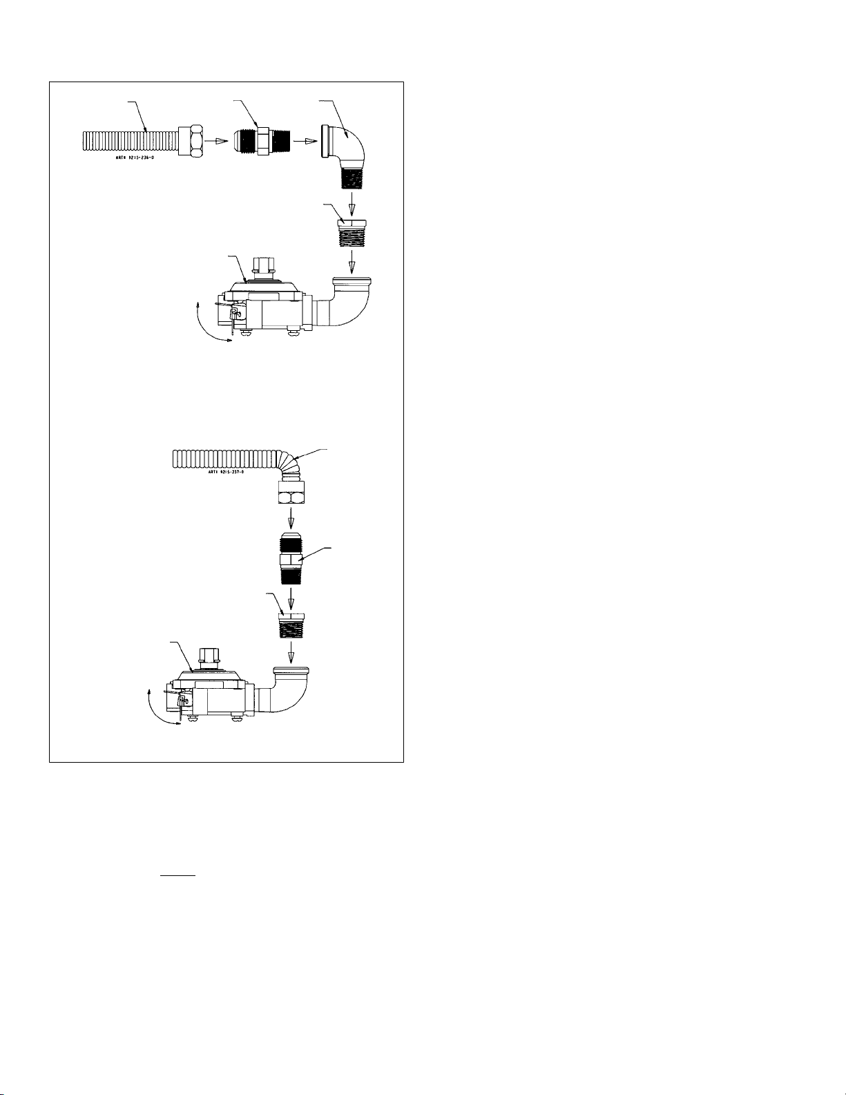
Recommended Gas Supply Connections
FLEXIBLE
SUPPLY
LINE
ADAPTER
1/2″ NPT MALE TO 3/8″ NPT FEMALE
ADAPTER BUSHING
REGULATOR
ON
REGULATOR
SHUT-OFF
VALVE
OFF
3/8″ NPT
STREET
ELBOW
FLEXIBLE
SUPPLY
LINE
a. A GAS CUTOFF VALVE SHOULD BE PUT IN AN
ACCESSIBLE LOCATION IN THE SUPPLY LINE
AHEAD OF THE RANGE, FOR TURNING ON AND
TURNING OFF GAS SUPPLY. If range is to be
connected to house piping with flexible or semi-rigid
metal connectors for gas appliances, CONNECTOR
NUTS MUST NOT BE CONNECTED DIRECTLY TO
PIPE THREADS. THE CONNECTORS MUST BE
INSTALLED WITH ADAPTORS PROVIDED WITH
THE CONNECTOR.
b. The house piping and/or range connector used to
connect the range to the main gas supply must be
clean, free of metal shavings, rust, dirt and liquids (oil
or water). Dirt, etc. in the supply lines can work its
way into the range manifold and in turn cause failure
of the gas valves or controls and clog burners and/or
pilot orifices.
CAUTION: DO NOT LIFT OR MOVE RANGE BY
DOOR HANDLES, OR BACKGUARD.
c. Turn off all pilots and main gas valve of other gas
appliances.
d. Turn off main gas valve at meter.
ADAPTER
1/2″ NPT MALE TO 3/8″ NPT FEMALE
REGULATOR
ON
REGULATOR
SHUT-OFF
VALVE
ADAPTER BUSHING
OFF
FIGURE 3
WHEN THE INSTALLER HAS COMPLETED
INSTALLATION OF THE APPLIANCE, LEAVE THE
APPLIANCE PRESSURE REGULATOR SHUT-OFF
VALVE IN THE “ON” POSITION.
e. Before connecting range, apply pipe thread
compound approved for LPG to all threads.
f. Use only a flexible connector to connect range to gas
supply at appliance pressure regulator using adaptors
supplied with connector. Regulator supplied with
range has 1/2″ NPT female connection.
NOTE: It is recommended to use a CSA certified
flexible connector no longer than 36″ (91.4 cm)
with a minimum BTU/HR rating of 88,200, and in
accordance with local codes.
See serial plate for type of gas range has been
manufactured for.
g. Turn on main gas valve at meter, and relight pilots at
other gas appliances.
h. Apply a non-corrosive leak detection fluid to all joints
and fittings in the gas connection between the supply
line shut-off valve and the range. Include gas fittings
and joints in the range if connections were disturbed
during installation. Check for leaks! Bubbles
appearing around fittings and connections will indicate
a leak. If a leak appears, turn off supply line gas
shut-off valve, tighten connections, turn on the supply
line gas shut off valve, and retest for leaks.
-- 6 --
CAUTION: NEVER CHECK FOR LEAKS WITH A
FLAME.
WHEN LEAK CHECK IS COMPLETE, WIPE OFF
ALL RESIDUE.
RANGE ADJUSTMENTS
Top Section -- Electric Ignition
To operate, push and turn top burner knob to the LITE
position. The top burner will light. To turn OFF spark after
the top burner has ignited, turn knob to HI setting.
NOTE: Top burners are not adjustable.
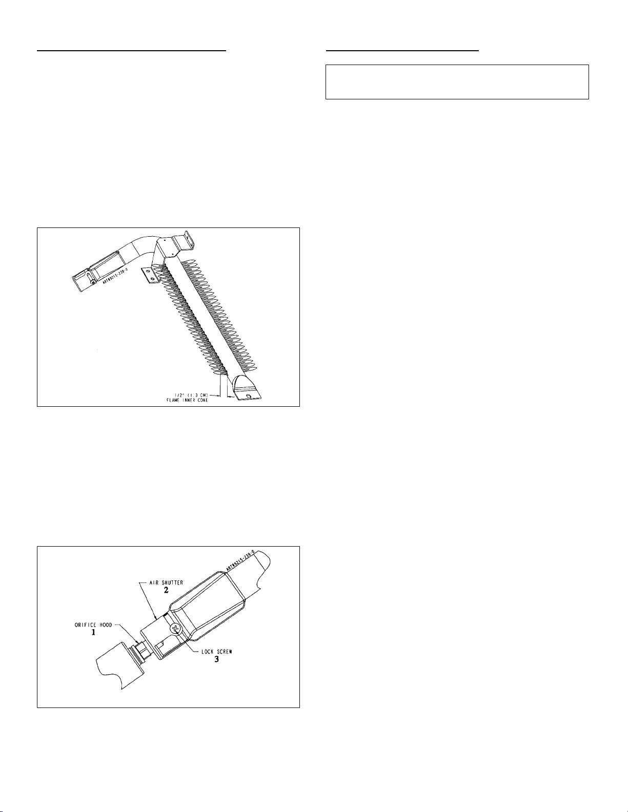
Air Shutter -- Bake/Broil Burner
NOTE: If oven burner does not ignite, check oven gas
shut-off position at the regulator.
a. The approximate length of the flame of oven burner is
a 1/2 inch distinct inner blue flame, figure 4.
GAS CONVERSION
SEE INSTRUCTIONS FOR GAS CONVERSION
LOCATED ON THE BACK OF THE RANGE.
FIGURE 4
b. Bake/broil burner flame can be checked as follows:
1. Yellow flame on burner -- open burner air shutter
to the widest opening that will not cause the flame
to lift or blow off the burner when cold. (See #2 on
figure 5). Some yellow tipping on LP is normal.
2. Distinct blue flame but lifting -- close burner air
shutter to the point where it will not cause the
flame to lift or blow off the burner when cold. (See
#2 on figure 5).
FIGURE 5
-- 7 --
 Loading...