

Jenn-Air Jenn-Air, Integrated Side by side refrigerators Service Manual

Service
Integrated
Side-by-Side
Refrigerators
Service Manual for Jenn-Air® models
This Base Manual covers Integrated
Side-by-Side Refrigerators
Refer to individual Technical Sheet for
information on specific models.
This manual is to be used by qualified appliance
technicians only. Maytag does not assume any
responsibility for property damage or personal
injury for improper service procedures done by
an unqualified person.
16021730
July 2002
!
!
!
Important Information
Pride and workmanship go into every product to provide our customers with quality products. It is possible, however,
that during its lifetime a product may require service. Products should be serviced only by a qualified service
technician who is familiar with the safety procedures required in the repair and who is equipped with the proper tools,
parts, testing instruments and the appropriate service manual. REVIEW ALL SERVICE INFORMATION IN THE
APPROPRIATE SERVICE MANUAL BEFORE BEGINNING REPAIRS.
Important Notices for Consumers and Servicers
WARNING
To avoid risk of serious injury or death, repairs should not be attempted by unauthorized personnel, dangerous
conditions (such as exposure to electrical shock) may result.
CAUTION
!
Maytag will not be responsible for any injury or property damage from improper service procedures. If performing
service on your own product, assume responsibility for any personal injury or property damage which may result.
To locate an authorized servicer, please consult your telephone book or the dealer from whom you purchased this
product. For further assistance, please contact:
MAYTAG APPLIANCES SALES COMPANY OR U.S. and Canada 1-800-Jenn-Air
ATTN:Jenn-Air CAIR
P.O. Box 2370 impaired, call 1-800-688-2080
Cleveland, TN 37320-2370
If outside the United States contact:
Recognize Safety Symbols, Words, and Labels
®
Center CALL U.S. customers using TTY for deaf, hearing
MAYTAG APPLIANCES SALES COMPANY
ATTN: Jenn-Air CAIR® Center
P.O. Box 2370
Cleveland, TN 37320-2370
Telephone: 1-800-Jenn-Air (1-800-536-6247)
DANGER
DANGERImmediate hazards which WILL result in severe personal injury or death.
WARNING
WARNINGHazards or unsafe practices which COULD result in severe personal injury or death.
CAUTION
!
CAUTIONHazards or unsafe practices which COULD result in minor personal injury or product or property
damage.
16021730 Rev. 0 2

Table of Contents
Important Information .................................................... 2
Component Testing ....................................................... 4
Service Procedures ....................................................... 7
Service Equipment ........................................................ 7
Drier Replacement ........................................................ 7
Refrigerant Precautions ................................................. 7
Line Piercing Valves ...................................................... 7
Open Lines ................................................................... 8
Dehydrating Sealed Refrigeration System ..................... 8
Leak Testing .................................................................. 8
Testing Systems Containing a
Refrigerant Charge ................................................... 8
Testing Systems Containing
No Refrigerant Charge ............................................. 8
Restrictions ................................................................... 8
Symptoms .............................................................. 8
Testing for Restrictions ........................................... 9
Evacuation and Charging ............................................... 9
Evacuation .............................................................. 9
Charging ................................................................ 10
Refrigerant Charge ................................................. 10
HFC134a Service Information ....................................... 11
Health, Safety, and Handling .................................. 11
Comparison of CFC12 and HFC134a Properties ..... 11
Replacement Service Compressor ................................12
Brazing ........................................................................12
Refrigerant Flow ...........................................................13
Cabinet Air Flow ........................................................... 14
Ice and Water Flow Diagram ........................................ 15
Water Valves Diagram .................................................. 16
Troubleshooting Chart................................................17
System Diagnosis ........................................................ 20
Disassembly Procedures
Compressor Replacement ...................................... 23
Condenser Replacement ........................................ 24
Evaporator Replacement ........................................ 25
Heat Exchanger Replacement ............................... 27
Condenser Fan ...................................................... 28
Freezer Fan ...........................................................28
Fresh Food Fan .....................................................28
Defrost Heater ....................................................... 29
Drain Pan and Drain Tube Heater ........................... 30
Defrost Thermistor .................................................30
Auto Damper Stepper ............................................30
Ice & Water Fountain PC Board .............................30
Touch Fountain Board ............................................32
Fountain Bracket ................................................... 32
Ice Crusher Bin & Shelf.......................................... 33
Climate Zone Technolgy (CZT) ...............................35
Climate Zone Bulb Upper ....................................... 36
Climate Zone Bulb Lower ....................................... 36
Cimate Zone Test ...................................................37
Diagnostic Mode Procedures .................................38
Power Supply Diagnostics .....................................39
Diagnostic Control Mode ........................................ 40
Appendix A
Owners Manual ........ ........................................A-2
Appendix B
Installation Guide ................................................. B-2
3 16021730 Rev. 0
Component Testing
!
WARNING
To avoid risk of electrical shock, personal injury, or death, disconnect electrical power source to unit, unless test
procedures require power to be connected. Discharge capacitor through a resistor before attempting to service.
Ensure all ground wires are connected before certifying unit as repaired and/or operational.
Component Description Test Procedures
Variable Capacity
Compressor
When compressor electrical circuit is
energized the DC powered compressor
is started at high speed or 4500 RPM
down to 1600 RPM. For low speed from
the compressor PCB board.
Resistance test
1. Disconnect power to unit.
2. Remove leads from compressor terminals.
3. Set ohmmeter to lowest scale.
4. Check for resistance between any two terminals. Resistance should be equal
between any two terminals.
5. If either compressor winding reads open (infinite or very high resistance) or
dead short (0 ohms), replace compressor.
Ground test
1. Disconnect power to refrigerator.
2. Remove compressor leads and use an ohmmeter set on highest scale.
3. Touch one lead to compressor body (clean point of contact) and other probe
to each compressor terminal.
• If reading is obtained, compressor is grounded and must be replaced.
Operation test
If voltage and motor winding tests do not show cause for failure, perform the
following test:
1. Activate the Diagnostic test mode (See Diagnostic test mode section)
2. Activate Test mode #16 (which is High Speed for compressor)
3. Check the A/C voltage between pins 1 and 2 of JP10 (Voltage should be
approximately 2.3VAC)
4. Verify that line voltage is available to Compressor PCB at CNO1 between
pins 2 and 5 If AC voltage is there.
5. Check voltage at CNO5 at pins 1 and 6 voltage should read approximately
230VAC
6. Check Voltage at CNO5 at pins 1 and 3 voltage should read approximately
230VAC
7. Check Voltage at CNO5 at pins 3 and 6 voltage should read approximately
230VAC
8. The readings at all three above readings should be the same if not bad
PCB board
9. If voltage is the same suspect a failed compressor.
16021730 Rev. 0
4
Component Testing
!
WARNING
To avoid risk of electrical shock, personal injury, or death, disconnect electrical power source to unit, unless test
procedures require power to be connected. Discharge capacitor through a resistor before attempting to service.
Ensure all ground wires are connected before certifying unit as repaired and/or operational.
Component Description Test Procedures
Condenser Condenser is a tube and fin construction
located in machine compartment.
Condenser is on high-pressure discharge
side of compressor. Condenser function
is to transfer heat absorbed by refrigerant
to ambient.
Higher-pressure gas is routed to
condenser where, as gas temperature is
reduced, gas condenses into a highpressure liquid state. Heat transfer takes
place because discharged gas is at a
higher temperature than air that is
passing over condenser. It is very
important that adequate airflow over
condenser is maintained.
Condenser is air cooled by condenser
fan motor. If efficiency of heat transfer
from condenser to surrounding air is
impaired, condensing temperature
becomes higher. High liquid temperature
means liquid will not remove as much
heat during boiling in evaporator as
under normal conditions. This would be
indicated by high than normal head
pressures, long run time, and high
wattage. Remove any lint or other
accumulation that would restrict normal
air movement through condenser.
Leaks in condenser can usually be detected by using an electronic leak detector
or soap solution. Look for signs of compressor oil when checking for leaks. A
certain amount of compressor oil is circulated with refrigerant.
Leaks in post condenser loop are rare because loop is a one-piece copper tube.
For minute leaks
1. Separate condenser from rest of refrigeration system and pressurize
condenser up to a maximum of 235 PSI with a refrigerant and dry nitrogen
combination.
2. Recheck for leaks.
WARNING
!
To avoid severe personal injury or death from sudden eruption of high
pressures gases, observe the following:
Protect against a sudden eruption if high pressures are required for leak
checking.
Do not use high-pressure compressed gases in refrigeration systems
without a reliable pressure regulator and pressure relief valve in the
lines.
From condenser the refrigerant flows into
a post condenser loop which helps
control exterior condensation on flange,
center mullion, and around freezer door.
Refrigerant the flows through the drier to
evaporator and into compressor through
suction line.
Refrigerator light
switch
Thermostat Thermostat is in a series circuit with
Single pole, single throw switch
completes circuit for light when door is
open.
terminal 2 of defrost timer, and defrost
heater. Circuit is complete if evaporator
fan motor operates when cold.
Controls the circuit from freezer
thermostat through defrost terminator to
defrost heater. Opens and breaks circuit
when thermostat senses preset high
temperature.
Check resistant across terminals.
Switch arm depressed
“NO” terminals Open
Switch arm up
“NO” terminals Closed
Test continuity across terminals.
With power off and evaporator coil below freezing, thermostat should show
continuity when checked with ohmmeter. See “Heater, evaporator (defrost)”
section for additional tests.
After defrost thermostat opens, thermostat remains open until end of defrost
cycle and refrigerator starts cooling again. Defrost thermostat senses a preset
low temperature and resets (closes).
16021730 Rev. 05
Component Testing
!
!
!
WARNING
To avoid risk of electrical shock, personal injury, or death, disconnect electrical power source to unit, unless test
procedures require power to be connected. Discharge capacitor through a resistor before attempting to service.
Ensure all ground wires are connected before certifying unit as repaired and/or operational.
Drier Drier is placed at post condenser loop
outlet and passes liquefied refrigerant to
capillary.
Desiccant (20) 8 x 12 4AXH - 7 M>S> Grams
Drier must be changed every time the system is opened for testing or
compressor replacement.
NOTE: Drier used in R12 sealed system is not interchangeable with
drier used in R134a sealed system. Always replace drier in R134a
system.
Before opening refrigeration system, recover HFC134a refrigerant for safe
disposal.
1. Cut drier out of system using the following procedure. Do not unbraze drier.
2. Applying heat to remove drier will drive moisture into the system.
3. Score capillary tube close to drier and break.
4. Reform inlet tube to drier allowing enough space for large tube cutter.
5. Cut circumference of drier 1 ¼" below condenser inlet tube joint to drier.
6. Remove drier.
7. Apply heat trap paste on post condenser tubes to protect grommets from high
heat.
8. Unbraze remaining part of drier. Remove drier from system.
9. Discard drier in safe place. Do not leave drier with customer. If refrigerator is
under warranty, old drier must accompany warranty claim.
WARNING
To avoid death or severe personal injury, cut drier at correct location.
Cutting drier at incorrect location will allow desiccant beads to scatter. If
spilled, completely clean area of beads.
Evaporator Inner volume of evaporator allows liquid
Evaporator defrost
heater
refrigerant discharged from capillary to
expand into refrigerant gas.
Expansion cools evaporator tube and fin
temperature to approximately -20
transferring heat from freezer section to
refrigerant.
Passing through suction line to
compressor, the refrigerant picks up
superheat (a relationship between
pressure and temperature that assures
complete vaporization of liquid
refrigerant) as the result of capillary tube
soldered to suction line.
Refrigerant gas is pulled through suction
line by compressor, completing
refrigeration cycle.
Activated when Main control board
activates defrost mode or when forced in
Diagnostic mode.
°
F
Test for leaks in evaporator with electronic leak detector or with soap solution.
Compressor oil is circulated with refrigerant; check for oil when checking for
leaks.
For minute leaks
1. Separate evaporator from rest of refrigeration system and pressurize
evaporator up to a maximum of 140 PSI with a refrigerant and dry nitrogen
combination.
2. Recheck for leaks.
WARNING
To avoid severe personal injury or death from sudden erruption of
high pressurres gases, observe the following:
• Protect against a sudden eruption if high pressures are required
for leak checking.
•
Do not use high pressure compressed gases in refrigeration
systems without a reliable pressure regulator and pressure relief
valve in the lines.
Check resistance across heaters.
If resistance heater is open and should be replaced.
In diagnostic mode test # 11 Energize heater (the defrost system should draw
about 3 amps).
16021730 Rev. 0
6
Service Procedures
!
WARNING
To avoid risk of electrical shock, personal injury, or death, disconnect electrical power source to unit, unless test
procedures require power to be connected. Discharge capacitor through a 10,000 ohm resistor before attempting
to service. Ensure all ground wires are connected before certifying unit as repaired and/or operational.
Service Equipment
Listed below is equipment needed for proper servicing
of HFC134a systems. Verify equipment is confirmed
by manufacturer as being compatible with HFC134a
and ester oil system.
Equipment must be exclusively used for HFC134a.
Exclusive use of equipment only applies to italic items.
Evacuation pump
Check with vacuum pump supplier to verify equipment
is compatible for HFC134a. Robinair, Model 15600
2 stage, 6 cubic feet per minute pump is
recommended.
Four-way manifold gauge set, with low loss hoses
Leak detector
Charging cylinder
Line piercing saddle valve
(Schroeder valves). Seals must be HFC134a and
ester oil compatible. Line piercing valves may be used
for diagnosis but are not suitable for evacuation or
charging, due to minute holes pierced in tubing. Do
not leave mechanical access valves on system.
Valves eventually will leak. Molecules of HFC134a are
smaller than other refrigerants and will leak where
other refrigerants would not.
Swagging tools
Flaring tools
Tubing cutter
Flux
Sil-Fos
Silver solder
Oil for swagging and flaring
Use only part # R0157532
Copper tubing
Use only part # R0174075 and # R0174076
Dry nitrogen
99.5% minimum purity, with -40°F or lower dew point
Crimp tool
Tube bender
Micron vacuum gauge
Process tube adaptor kit
Heat trap paste
ICI appliance grade HFC134a
Drier Replacement
Before opening refrigeration system, recover HFC134a
refrigerant for safe disposal.
Every time sealed HFC134a system is repaired, drier
filter must be replaced.
Cut drier out of system by completing the following
steps. Do not unbraze drier filter. Applying heat to
remove drier will drive moisture into system.
1. Score capillary tube close to drier and break.
2. Reform inlet tube to drier allowing enough space
for large tube cutter.
3. Cut circumference of drier at 1-1/4", below
condenser inlet tube joint to drier.
4. Remove drier.
5. Apply heat trap paste on post condenser tubes to
protect grommets from high heat.
6. Unbraze remaining part of drier. Remove drier
from system.
7. Discard drier in safe place. Do not leave drier with
customer. If refrigerator is under warranty, old
drier must accompany warranty claim.
Refrigerant Precautions
WARNING
!
To avoid risk of personal injury, do not allow
refrigerant to contact eyes or skin.
CAUTION
!
To avoid risk of property damage, do not use
refrigerant other than that shown on unit serial
number identification plate.
NOTE: All precautionary measures recommended by
refrigerant manufacturers and suppliers apply
and should be observed.
Line Piercing Valves
Line piercing valves can be used for diagnosis, but are
not suitable for evacuating or charging due to holes
pierced in tubing by valves.
NOTE: Do not leave line piercing valves on system.
Connection between valve and tubing is not
hermetically sealed. Leaks will occur.
7 16021730 Rev. 0
Service Procedures
!
WARNING
To avoid risk of electrical shock, personal injury, or death, disconnect electrical power source to unit, unless test
procedures require power to be connected. Discharge capacitor through a 10,000 ohm resistor before attempting
to service. Ensure all ground wires are connected before certifying unit as repaired and/or operational.
Testing Systems Containing No Refrigerant Charge
1. Connect cylinder of nitrogen, through gauge
Open Lines
During any processing of refrigeration system, never
leave lines open to atmosphere. Open lines allow water
vapor to enter system, making proper evacuation more
difficult.
Dehydrating Sealed Refrigeration System
Moisture in a refrigerator sealed system exposed to
heat generated by the compressor and motor reacts
chemically with refrigerant and oil in the system and
forms corrosive hydrochloric and hydrofluoric acids.
These acids contribute to breakdown of motor winding
insulation and corrosion of compressor working parts,
causing compressor failure.
In addition, sludge, a residue of the chemical reaction,
coats all surfaces of sealed system, and will
eventually restrict refrigerant flow through capillary
tube.
To dehydrate sealed system, evacuate system (see
paragraph Evacuation).
Leak Testing
DANGER
!
To avoid risk of serious injury or death from violent
explosions, NEVER use oxygen or acetylene for
pressure testing or clean out of refrigeration
systems. Free oxygen will explode on contact with
oil. Acetylene will explode spontaneously when put
under pressure.
It is important to check sealed system for refrigerant
leaks. Undetected leaks can lead to repeated service
calls and eventually result in system contamination,
restrictions, and premature compressor failure.
Refrigerant leaks are best detected with halide or
electronic leak detectors.
Testing Systems Containing a Refrigerant Charge
1. Stop unit operation (turn refrigerator off).
2. Holding leak detector exploring tube as close to
system tubing as possible, check all piping, joints,
and fittings.
NOTE: Use soap suds on areas leak detector cannot
reach or reliably test.
manifold, to process tube of compressor and liquid line
strainer.
2. Open valves on nitrogen cylinder and gauge manifold.
Allow pressure to build within sealed system.
3. Check for leaks using soap suds.
If a leak is detected in a joint, do not to attempt to repair
by applying additional brazing material. Joint must be
disassembled, cleaned and rebrazed. Capture refrigerant
charge (if system is charged), unbraze joint, clean
allparts, then rebraze.
If leak is detected in tubing, replace tubing. If leak is
detected in either coil, replace faulty coil.
Restrictions
Symptoms
Restrictions in sealed system most often occur at
capillary tube or filter drier, but can exist anywhere on
liquid side of system.
Restrictions reduce refrigerant flow rate and heat
removal rate. Wattage drops because compressor is
not circulating normal amount of refrigerants.
Common causes of total restrictions are moisture,
poorly soldered joints, or solid contaminants. Moisture
freezes at evaporator inlet end of capillary tube. Solid
contaminants collect in filter drier.
If restriction is on low side, suction pressure will be in a
vacuum and head pressure will be near normal.
If restriction is on high side, suction pressure will be in
a vacuum and head pressure will be higher than normal
during pump out cycle.
Refrigeration occurs on low pressure side of partial
restriction. There will be a temperature difference at the
point of restriction. Frost and/or condensation will be
present in most case at the point of restriction. Also,
system requires longer to equalize.
Slight or partial restriction can give the same
symptoms as refrigerant shortage including lower than
normal back pressure, head pressure, wattage, and
warmer temperatures.
Total restriction on the discharge side of compressor,
when restriction is between compressor and first half of
condenser, results in higher than normal head pressure
and wattage while low side is being pumped out.
16021730 Rev. 0 8

Service Procedures
!
WARNING
To avoid risk of electrical shock, personal injury, or death, disconnect electrical power source to unit, unless test
procedures require power to be connected. Discharge capacitor through a 10,000 ohm resistor before attempting
to service. Ensure all ground wires are connected before certifying unit as repaired and/or operational.
Testing for Restrictions
To determine if a restriction exists:
1. Attach gauge and manifold between suction and
discharge sides of sealed system.
2. Turn unit on and allow pressure on each side to
stabilize. Inspect condenser side of system. Tubing on
condenser should be warm and temperature should be
equal throughout (no sudden drops at any point along
tubing).
If temperature of condenser tubing is consistent
throughout, go to step 4.
If temperature of condenser tubing drops suddenly at
any point, tubing is restricted at point of temperature
drop (if restriction is severe, frost may form at point
of restriction and extend down in direction of
refrigerant flow in system). Go to step 5.
3. Visually check system for kinks in refrigeration line
which is causing restriction. Correct kink and repeat
step 2.
4. Turn unit off and time how long it takes high and low
pressure gauges to equalize:
If pressure equalization takes longer than 10
minutes, a restriction exists in the capillary tube or
drier filter. Go to step 5.
If pressure equalization takes less than 10 minutes,
system is not restricted. Check for other possible
causes of malfunction.
5. Recover refrigerant in sealed system.
NOTE: Before opening any refrigeration system, capture
refrigerant in system for safe disposal.
6. Remove power from unit.
CAUTION
!
To avoid risk of personal injury or property damage,
take necessary precautions against high
temperatures required for brazing.
7. Remove and replace restricted device.
8. Evacuate sealed system.
9. Charge system to specification.
NOTE: Do not use captured or recycled refrigerant in
Maytag units. Captured or recycled refrigerant
voids any Maytag and/or compressor
manufacturer's warranty.
NOTE: Charge system with exact amount of refrigerant.
Refer to unit nameplate for correct refrigerant
charge. Inaccurately charged system will cause
future problems.
Evacuation and Charging
CAUTION
!
To avoid risk of fire, sealed refrigeration system must
be air free. To avoid risk of air contamination, follow
evacuation procedures exactly.
NOTE: Before opening any refrigeration system, EPA
regulations require refrigerant in system to be
captured for safe disposal.
Proper evacuation of sealed refrigeration system is an
important service procedure. Usable life and operational
efficiency greatly depends upon how completely air,
moisture and other non-condensables are evacuated
from sealed system.
Air in sealed system causes high condensing
temperature and pressure, resulting in increased power
requirements and reduced performance.
Moisture in sealed system chemically reacts with
refrigerant and oil to form corrosive hydrofluoric and
hydrochloric acids. These acids attack motor windings
and parts, causing premature breakdown.
Before opening system, evaporator coil must be at
ambient temperature to minimize moisture infiltration
into system.
Evacuation
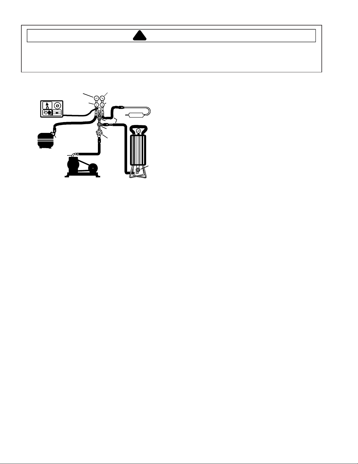
To evacuate sealed refrigeration system:
1. Connect vacuum pump, vacuum tight manifold set with
high vacuum hoses, thermocouple vacuum gauge and
charging cylinder as shown in illustration.
Evacuation should be done through I.D. opening of
tubes not through line piercing valve.
2. Connect low side line to compressor process tube.
3. Connect high side line to drier/process tube.
4. Evacuate both simultaneously. With valve C and F
closed, open all other valves and start vacuum pump.
9 16021730 Rev. 0
Service Procedures
!
WARNING
To avoid risk of electrical shock, personal injury, or death, disconnect electrical power source to unit, unless test
procedures require power to be connected. Discharge capacitor through a 10,000 ohm resistor before attempting
to service. Ensure all ground wires are connected before certifying unit as repaired and/or operational.
Charging
NOTE: Do not use captured or recycled refrigerant in
Maytag units. Captured or recycled refrigerant
voids any warranty.
NOTE: Charge system with exact amount of refrigerant.
Refer to unit serial plate for correct refrigerant
charge. Inaccurately charged system will cause
future problems.
To charge system:
1. Close valves A to vacuum pump and C to vacuum
gauge and E to low side manifold gauge.
2. Set scale on dial-a-charge cylinder for corresponding
HFC134a pressure reading.
3. Open valve F to charging cylinder and let exact
amount of refrigerant flow from cylinder into system.
Close valve.
Low side gauge pressure should rise shortly after
opening charging cylinder valve as system pressure
equalizes through capillary tube.
If pressure does not equalize, a restriction typically
exists at capillary/drier braze joint.
4. If pressure equalizes, open valve E to low side
manifold gauge and pinch off high side drier process
tube.
5. Start compressor and draw remaining refrigerant from
charging hoses and manifold into compressor through
compressor process tube.
6. To check high side pinch-off drier process tube. Close
valve D to high side gauge. If high side pressure
rises, repeat high side pinch-off and open valve D.
Repeat until high side pinch-off does not leak.
7. Pinch-off compressor process tube and remove
charging hose. Braze stub closed while compressor is
operating.
8. Disconnect power. Remove charging hose and braze
high side drier process tube closed.
9. Recheck for refrigerant leaks.
Refrigerant Charge
Refrigerant charge in all capillary tube systems is
critical and exact amount is required for proper
performance. Factory charges are shown on serial
plate.
NOTE: Do not use refrigerant other than shown on serial
plate.
E
High Side Gauge
D
Valve
Charg ing Hose
C
B
A
Drier/Process Tube
F
Valve
Charging
Cylinder
Thermistor
Vacuum Gauge
Compressor
Low Side Gauge
Charging Hose
Compressor
Process
Tube
.6 cm Copper
Tubing
Valve
Vacuum Pump
Equipment Setup For Evacuation And Charging
5. After compound gauge (low side) drops to
approximately 29 inches gauge, open valve C to
vacuum thermocouple gauge and take micron reading.
NOTE: A high vacuum pump can only produce a good
vacuum if oil in pump is not contaminated.
6. Continue evacuating system until vacuum gauge
registers 600 microns.
7. At 600 microns, close valve A to vacuum pump and
allow micron reading in system to balance. Micron
level will rise.
If in 2 minutes, micron level stabilizes at 1000
microns or below, system is ready to be charged.
If micron level rises above 1000 microns and
stabilizes, open valve A and continue evacuating.
If micron reading rises rapidly and does not stabilize,
a leak still exists in system.
Close valve A to vacuum pump and valve C to
vacuum gauge. Invert charging cylinder and open
charging cylinder valve F to add partial charge for
leak checking. With leak detector, check manifold
connections and system for leaks. After locating
leak, capture refrigerant, repair leak, and begin at
step 1.
16021730 Rev. 0 10
Service Procedures
!
WARNING
To avoid risk of electrical shock, personal injury, or death, disconnect electrical power source to unit, unless test
procedures require power to be connected. Discharge capacitor through a 10,000 ohm resistor before attempting
to service. Ensure all ground wires are connected before certifying unit as repaired and/or operational.
HFC134a Service Information
HFC134a is alternative refrigerant for CFC12. HFC134a
has an ozone depletion potential (ODP) factor of 0.0
and a global warming potential (GWP) factor of 0.27.
HFC134a is not flammable and has acceptable toxicity
levels. HFC134a is not interchangeable with CFC12.
There are significant differences between HFC134a and
CFC12 which must be considered when handling and
processing refrigeration system.
Health, Safety, and Handling
Health, safety and handling considerations for
HFC134A are virtually no different than those for
CFC12.
Properties/Characteristics CFC12 HFC134a
Ozone Depletion Potential
(ODP)
Global Warming Potential
(GPW)
Molecular weight 121 102
Boiling point at 1 atmospher e -22°F (-30°C) -15°F (-
Vapor pressure at 77°F
(25°C)
Liquid density at 77°F (25°C) 82 lb/ft
Flammability No No
High-side system operating
Pressure at 65°F (18°C)
Low-side system operating
Pressure at 65°F (18°C)
1.0* 0.0*
3.2* 0.27*
80 psig 82 psig
3
HFC134a approximately 3 psig
higher than CFC12
HFC134a approximately 2 psig
lower than CFC12
126°C)
75 lb/ft
3
Health, Safety, and
Handling
Allowable overall
exposure limit
Vapor exposure to skin No effect Same
Liquid exposure to skin Can cause frostbite S ame
Vapor exposure to eye Very slight eye irritant Same
Liquid exposure to eye Can cause frostbite Sam e
Above minimum exposure
limit
Safety and handling Wear appropriate skin
Spill management Remove or extinguish
Fire explosion hazards May decompose if
Disposal procedures Recycle or reclaim. Same
1,000 ppm Same
Can cause Asphyxiation,
Tachycardia, and Cardia
Arrhythmias
and eye protection. Use
with adequate
ventilation.
ignition or combustion
sources. Evacuate or
ventilate area.
contact with flames and
heating elements.
Container may explode
if heated due to resulting
pressure rise.
Combustion products
are toxic.
CFC12 HFC134a
Same
Same
Same
Same
Comparison of CFC12 and HFC134a Properties
To minimize contamination, exercise extreme care
when servicing HFC134A sealed systems.
No trace of other refrigerants is allowed in HFC134a
systems. Chlorinated molecules in other refrigerants
such as CFC12, etc. will lead to capillary tube plugging.
Ester oil is used in HFC134a systems. Do not use
mineral oil. HFC134a and mineral oils cannot be mixed.
If mineral oils were used in HFC134a systems, lubricant
would not return to compressor and would cause early
compressor failure. If significant amount of oil has been
lost from compressor, replace oil rather than adding oil.
Ester oils used in HFC134a systems are so
hydroscopic that by the time an inadequate system
performance is detected, oil will be saturated with
moisture.
CFC12 has much higher tolerance to system
processing materials, such as drawing compounds, rust
inhibitors, and cleaning compounds, than HFC134a.
Such materials are not soluble in HFC134a systems. If
materials were to be washed from system surfaces by
ester oils, they could accumulate and eventually plug
capillary tube.
Care must be taken to minimize moisture entering
HFC134a system. Do not leave compressor or system
open to atmosphere for more than 10 minutes.
Excessive moisture in HFC134a system will react with
compressor oil and generate acid.
Compressor must be replaced when performing low side
leak repair.
Drier filter must always be replaced.
11 16021730 Rev. 0
Service Procedures
!
WARNING
To avoid risk of electrical shock, personal injury, or death, disconnect electrical power source to unit, unless test
procedures require power to be connected. Discharge capacitor through a 10,000 ohm resistor before attempting
to service. Ensure all ground wires are connected before certifying unit as repaired and/or operational.
Important: Unbrazing drier filter from tubing will drive
moisture from desiccant and into system, causing
acids to form. Do not unbraze filter drier from tubing. If
CFC12 service drier was installed in HFC134A system,
drier could overload due to excessive moisture.
HFC134a compatible copper tubing, part #R0174075 (1/
4" O.D. X 18" length) and part #R0174076 (5/16" O.D. X
24" length) must be used when replacing tubing.
Avoid system contamination by using Towerdraw E610
evaporating oil, part # R0157532, when flaring,
swagging, or cutting refrigeration tubing.
Replacement Service Compressor
HFC134a service compressors will be charged with
ester oil and pressurized with dry nitrogen. Before
replacement compressor is installed, pull out 1 rubber
plug. A pop from pressure release should be heard. If a
pop sound is not heard, do not use compressor.
Positive pressure in compressor is vital to keep
moisture out of ester oil. Do not leave compressor open
to atmosphere for more than 10 minutes.
Compressor Testing Procedures
WARNING
!
To avoid death or severe personal injury, never use
oxygen, air or acetylene for pressure testing or clean
out of refrigeration system. Use of oxygen, air, or
acetylene may result in violent explosion. Oxygen
may explode on contact with oil and acetylene will
spontaneously explode when under pressure.
Refer to Technical Data Sheet Temperature
Relationship Chart for operating watts, test points, and
temperature relationship test for unit being tested.
Temperature testing is accomplished by using 3 lead
thermocouple temperature tester in specific locations.
Test point T-1 is outlet on evaporator coil and T-2 is
inlet. Test point T-3 is suction tube temperature midway
between where armaflex ends and suction port of
compressor (approximately 12 inches from
compressor).
Thermocouple tips should be attached securely to
specified locations.
Do not test during initial pull down. Allow one off cycle
or balanced temperature condition to occur before
proceeding with testing.
Refrigerator must operate minimum of 20 minutes after
thermocouples are installed.
Turn control to colder to obtain required on time.
Wattage reading must be recorded in conjunction with
temperature test to confirm proper operation.
Suction and head pressures are listed on Temperature
and Relationship Chart. Normally these are not
required for diagnosis but used for confirmation on
systems which have been opened.
Brazing
CAUTION
!
To avoid risk of personal injury or property damage,
take necessary precautions against high
temperatures required for brazing.
Satisfactory results require cleanliness, experience,
and use of proper materials and equipment.
Connections to be brazed must be properly sized, free
of rough edges, and clean.
Generally accepted brazing materials are:
Copper to copper joints: SIL-FOS (alloy of 15 percent
silver, 80 percent copper, and 5 percent phosphorous).
Use without flux. Recommended brazing temperature is
approximately 1400°F. Do not use for copper to steel
connection.
Copper to steel joints: SILVER SOLDER (alloy of 30
percent silver, 38 percent copper, 32 percent zinc). Use
with fluoride based flux. Recommended brazing
temperature is approximately 1200°F.
Steel to steel joints: SILVER SOLDER (see copper
to steel joints).
Brass to copper joints: SILVER SOLDER (see copper
to steel joints).
Brass to steel joints: SILVER SOLDER (see copper
to steel joints).
16021730 Rev. 0 12
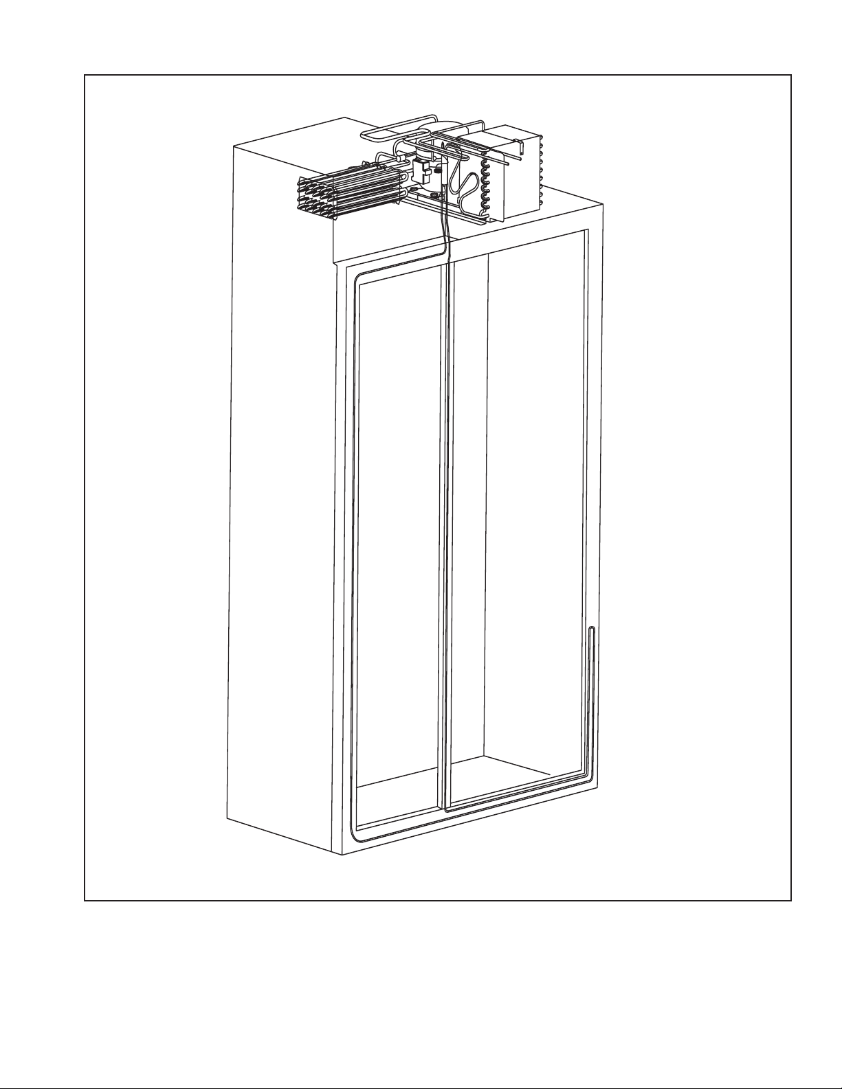
Refrigerant Flow
Side by Side
Refrigerant Flow Diagram
13 16021730 Rev. 0
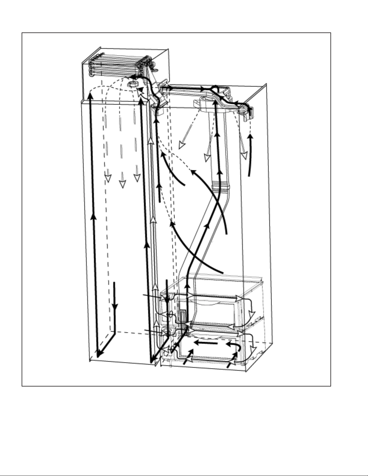
Cabinet Air Flow
Side by Side
Cabinet Air Flow Diagram
16021730 Rev. 0 14
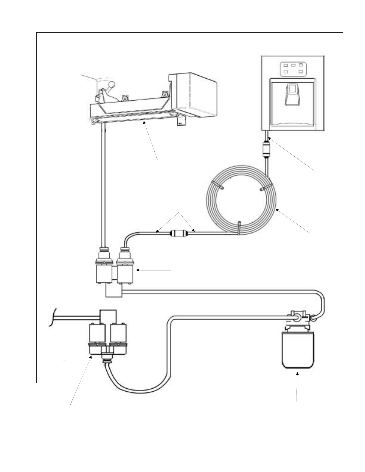
Ice and Water Dispenser Diagram
Ice Maker
5/16" Water line
to Dispenser
1/4" Water Line
Secondary Water Valve
Water Coil
Primary Water Valve
Side by Side
Water Filter
Ice and Water Flow Diagram
15 16021730 Rev. 0
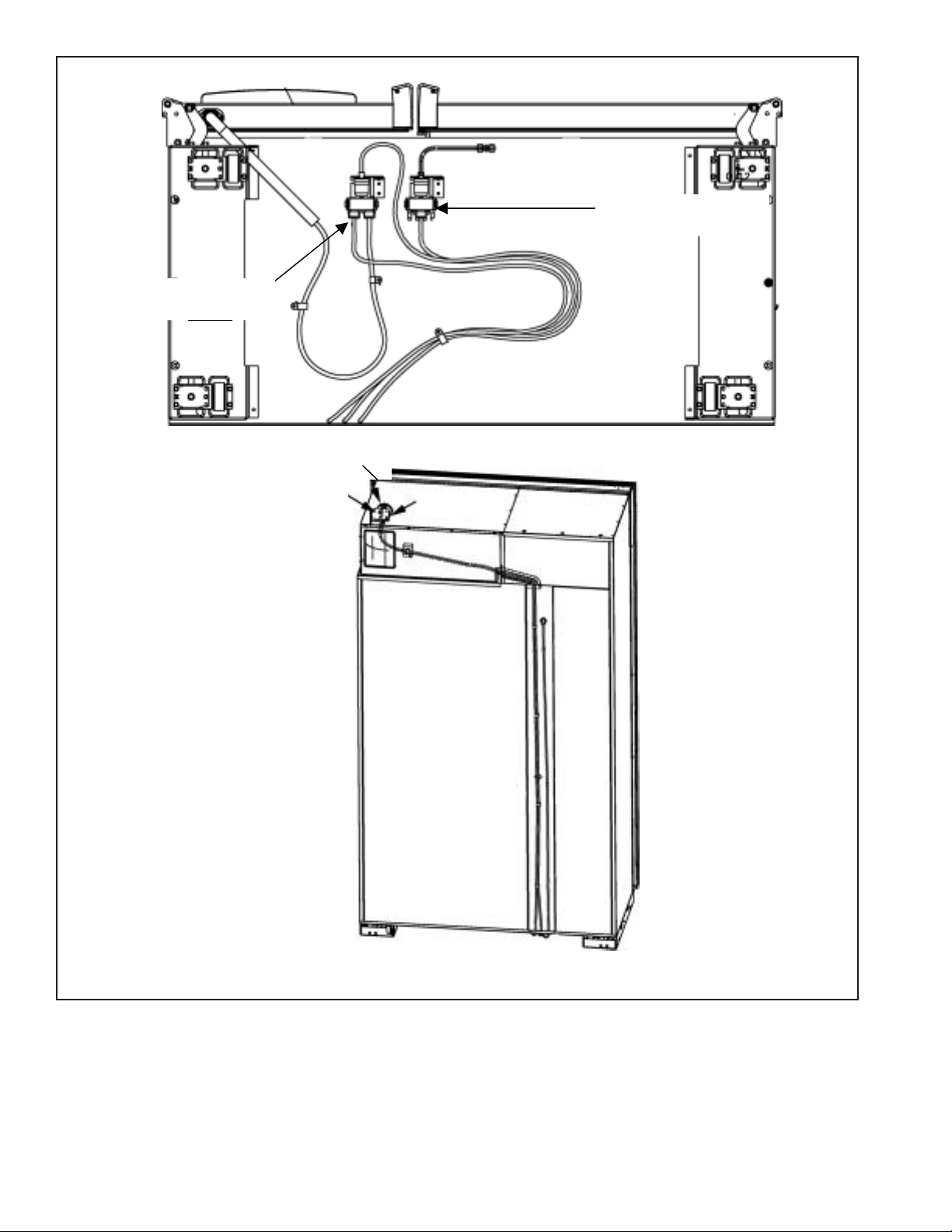
Water Valves Diagram
Secondary Valve
Bypass
Filter Head
Primary Valve
Bottom View
Back View
16021730 Rev. 0 16

Troubleshooting Chart
!
WARNING
To avoid risk of electrical shock, personal injury, or death, disconnect electrical power source to unit, unless test
procedures require power to be connected. Discharge capacitor through a resistor before attempting to service.
Ensure all ground wires are connected before certifying unit as repaired and/or operational.
Troubleshooting chart on following pages contains symptoms that may be seen in malfunctioning units. Each
symptom is accompanied by one or more possible causes and by a possible remedy or test to determine if
components are working properly.
Symptom Possible Causes Corrective Action
Unit does not run
Refrigerator sect i on too wa rm
No power to unit Check for power at outlet. Check
fuse box/circuit breaker for blown
fuse or tripped breaker. Replace or
reset.
Faulty power cord Check with test light at unit; if no
circuit and current is indicated at
outlet, replace or repair.
Low voltage Check input voltage for proper
voltage. Take appropriate action to
correct voltage supply problem.
Faulty compressor Check compressor motor windings
for opens/shorts.
Perform compressor diagnostic test
Replace if necessary.
Excessive door opening Consumer education
Overloading of shelves Consumer education
Warm or hot foods placed in cabinet Consumer education
Cold control set too warm Set control to colder setting.
Poor door seal Level cabinet. Adjust hinges.
Replace gasket.
Refrigerator airflow Check auto damper is opening by
removing grille. With door open,
damper should open. Replace if
faulty.
Interior light remains on Check switch. Replace if necessary.
Faulty condenser fan or evaporator
fan
Faulty compressor Replace compressor.
Check fan and wiring. Replace if
necessary.
17 16021730 Rev. 0
Troubleshooting Chart
!
WARNING
To avoid risk of electrical shock, personal injury, or death, disconnect electrical power source to unit, unless test
procedures require power to be connected. Discharge capacitor through a resistor before attempting to service.
Ensure all ground wires are connected before certifying unit as repaired and/or operational.
Symptom Possible Causes Corrective Action
Refrigerator section too cold
Freezer and refrigerator sections too
warm
Unit runs continuously
Noisy operation
Refrigerator temperature control set
too cold
Refrigerator air f l o w not pro per ly
adjusted
Temperature controls set too warm Reset temperature controls.
Poor door seal Level cabinet. Adjust hinges.
Dirty condenser or obstructed grille Check condenser and grille. Clean.
Faulty control Test control. Replace if failed.
Refrigerant shortage or restriction Check for leak or restriction. Repair,
Freezer temp control set too cold Adjust freezer temperature control. Freezer section too cold
Faulty control Test control. Replace if failed.
Temperature control set too cold Adjust temperature control.
Dirty condenser or obstructed grille Check condenser and grille. Clean.
Poor door seal Level cabinet. Adjust hinges.
Interior light remains on Check switch. Replace if necessary.
Faulty condenser fan or evaporator
fan
Faulty control Test control. Replace if failed.
Refrigerant shortage or restriction Check for leak or restriction. Repair,
Refrigerant overcharge Check for overcharge. Evacuate and
Air in system Check for low side leak. Repair,
Loose flooring or floor not firm Repair floor or brace floor.
Cabinet not level Level cabinet.
Tubing in contact with cabinet, other
tubing, or other metal
Drip pan vibrating Adjust drain pan.
Fan hitting another part Ensure fan properly aligned and all
Worn fan motor bearings Check motor for loss of lubricant or
Compressor mounting grommets
worn or missing. Mounting hardware
loose or missing
Free or loose parts causing or
allowing noise duri ng op era ti on
Adjust refrigerator temperature
control.
Check air flow.
Replace gasket.
evacuate and recharge s ystem.
Replace gasket.
Check fan and wiring. Replace if
necessary.
evacuate and recharge s ystem.
recharge system.
evacuate and recharge s ystem.
Adjust tubing.
attaching hardware and brackets are
tight and not worn. Tighten or
replace.
worn bearings. Replace if necessary.
Tighten hardware. Replace
grommets if necessary.
Inspect unit for parts that may have
worked free or loose or missing
screws. Repair as required.
16021730 Rev. 0 18
Troubleshooting Chart
!
WARNING
To avoid risk of electrical shock, personal injury, or death, disconnect electrical power source to unit, unless test
procedures require power to be connected. Discharge capacitor through a resistor before attempting to service.
Ensure all ground wires are connected before certifying unit as repaired and/or operational.
Symptom Possible Causes Corrective Action
Frost or ice on evaporator
Defrost thermostat faulty Check defrost thermostat. Replace if
failed.
Evaporator fan faulty Check fan motor. Replace if failed.
Defrost heater remains open Check defrost heater continuity.
Replace if failed.
Defrost control faulty Check control and replace if failed.
Open wire or connector Check wiring and connections.
Repair as necessary.
Refrigerant shortage or restriction Check for leak or restriction. Repair,
evacuate and recharge s ystem.
Supply voltage out of specification Check input voltage. Correct any
supply problems.
Faulty fan motor Check fan motor. Replace if failed.
Restricted air flow Check condenser and grille for dirt.
Clean.
Refrigerant shortage or restriction Check for leak or restriction. Repair,
evacuate and recharge s ystem.
19 16021730 Rev. 0
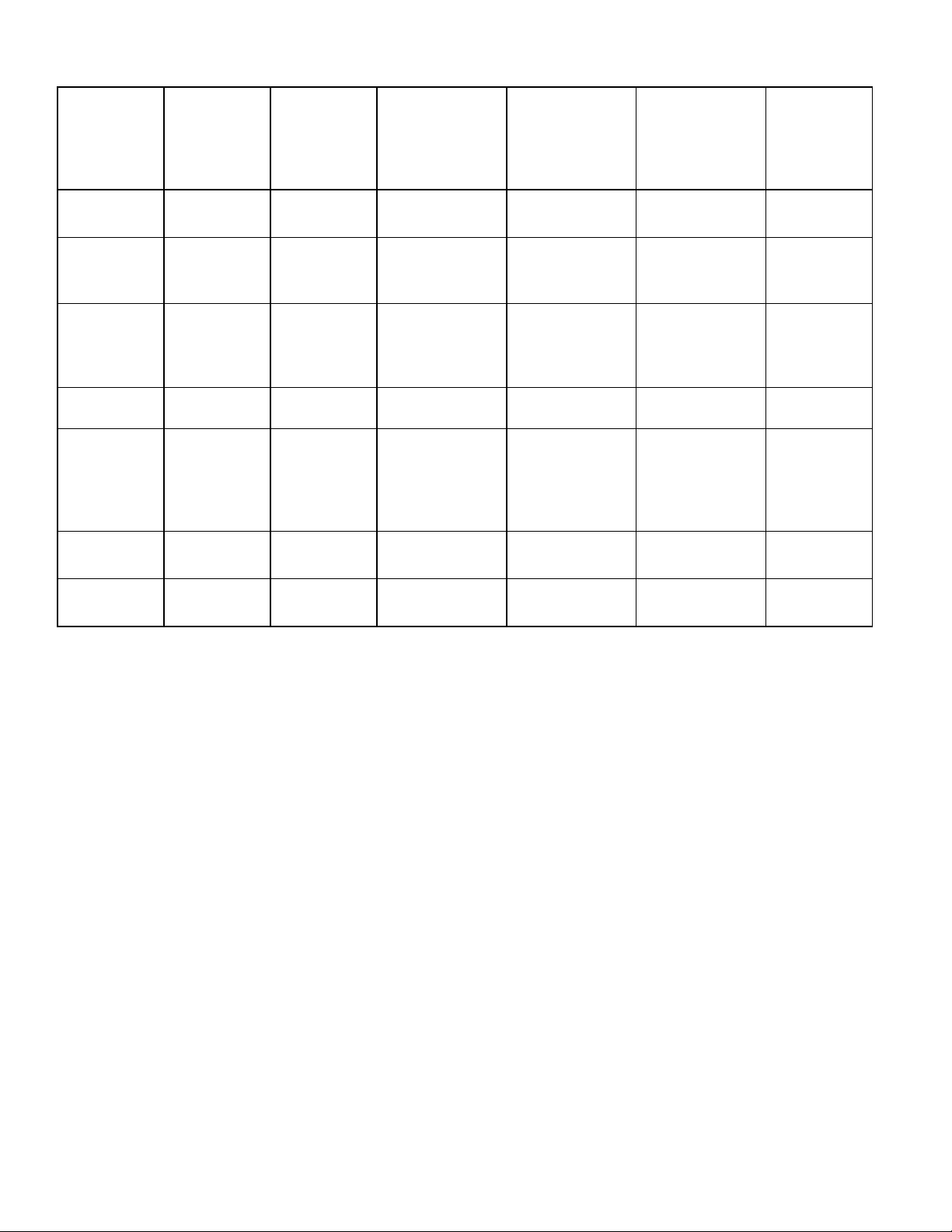
System Diagnosis
SUCTION
PRESSURE
CONDITION
Refrigerant
Overcharge
Shortage of
Refrigerant
Partial
Restriction
Air in System Near Normal Increase Warmer Warmer Warmer Increase
Low Ambient
Installations
(High
Ambients the
Reverse)
Additional
Heat Load
VARIATION
FROM
NORMAL
Increase Increase Warmer Warmer Colder Increase
Decrease
Decrease
Decrease Decrease Colder Warmer Warmer Decrease
Increase Increase Warmer Warmer Warmer Increase
HEAD
PRESSURE
VARIATION
FROM
NORMAL
Decrease or
Increase
See Text
Decrease or
Increase
See Text
Note 2
T1 INLET
TEMPERATURE
VARIATION
FROM NORMAL
Colder Warmer Warmer Decrease
Colder Warmer Warmer Decrease
T2 OUTLET
TEMPERATURE
VARIATION
FROM NORMAL
T3 SUCTION
TEMPERATURE
VARIATION
FROM NORMAL
WATTAGE
VARIATION
FROM
NORMAL
Inefficient
Compressor
Increase
Normal or
Decrease
Warmer or
Colder
Symptoms of an Overcharge
Above normal freezer temperatures.
Longer than normal or continuous run.
Freezing in refrigerator.
Higher than normal suction and head pressure.
Higher than normal wattage.
Evaporator inlet and outlet temperatures warmer than
normal.
Suction tube temperature below ambient. Always
check for separated heat exchanger when suction
temperature is colder than ambient.
Various conditons could indicate an overcharge. For
example, if the cooling coil is not defrosted at regular
intervals, due to a failure of the defrost system, the
refrigerant will "flood out" and cause the suction line to
frost or sweat. The cause of this problem should be
corrected rather than to purge refrigerant from the
sytem. Running the freezer section colder than
necessary (-2 to -1 F. is considered normal package
temperatures) or continuous running of the compressor
for a variety of reasons, or the freezer fan motor not
running, may give the indication of an overcharge.
Warmer Warmer Decrease
Symptoms of Refrigeration Shortage
Rise in food product temperature in both
compartments. (See Note 1 below.)
Long or continuous run time.
Look for obvious traces of oil that would occur due to a
leak or cracked refrigerant line.
Lower than normal wattage.
Compressor will be hot to touch because of the heat
generated by the motor windings from long continuous
running. It will not be as hot as it would be with a full
charge and long run times for some other reason such
as a dirty condenser.
Depending on the amount of the shortage, the
condenser will not be hot, but closer to room
temperature. The capillary tube will be warmer than
normal from a slight shortage.
If the leak is on the high side of the system, both
gauges will show lower than normal readings and will
show progressively lower readings as this charge
becomes less. The suction pressure guage will
probably indicate a vacuum.
If the leak is on the low side of the system the suction
pressure guage will be lower than normal - probably in
a vacuum - and the head pressure gauge will be
higher than normal. It will probably continue to
become higher because air drawn in through the leak
is compressed by the compressor and accumulates in
16021730 Rev. 0 20

System Diagnosis
the high side (condenser) of the system.
Only partial frosting of evaporator instead of even
frosting of entire coil.
NOTE 1: Usually the first thing that is noticed by the
user is a rise in temperature foods. Although
temperatures will rise in both the freezer section
and the food compartment, the frozen meats
and vegetables will not thaw immediately. The
customer doesn't associate the problem with
the freezer section and will first notice that milk
and other food beverages are not cold enough.
Under some circumstances, such as in the case of
forced air meatkeeper model with a slight shortage of
refrigerant, freezing in the food compartment may be
experienced due to the additional running time. With a
refrigerant leak, however, it always gets worse and as
the refrigerant charge decreases the temperature will
continue to rise.
With a shortage of refrigerant the capillary line will not
have a full column of liquid. As a result, there is a
noticeable hissing sound in the evaporator. This should
not be mistaken for the regular refrigerant boiling
sounds that would be considered normal.
Symptoms of a Restriction
Always remember refrigeration (cooling) occurs on the
low pressure side of a partial restriction (obviously a
total restriction will completely stop the circulation of
refrigerant and no cooling will take place).
Physically feel the refrigeration lines when a restriction
is suspected. The most common place for a restriction
is at the drier-filter or at the capillary tube inlet or outlet.
If the restriction is not total there will be a temperature
difference at the point of restriction, the area on the
evaporator side will be cooler. In many cases frost and/
or condensation will be present. A longer time is
required for the system to equalize.
Any kinked line will cause a restriction so the entire
system should be visually checked.
A slight restriction will give the same indications as a
refrigerant shortage with lower than normal back
pressure, head pressure, and wattage, warmer product
temperatures.
NOTE 2: If a total restriction is on the discharge side of
the compressor, higher than normal head
pressures and wattages would result. This is
true only while the low side is being pumped out
and if the restriction was between the
compressor and the first half of the condenser.
21 16021730 Rev. 0
To diagnose for a restriction versus a refrigerant
shortage, discharge the system, replace the drier-filter,
evacuate and recharge with the specified refrigerant
charge. If the unit performs normally three possibilities
exist: 1) refrigerant loss, 2) partially restricted drierfilter, and 3) moisture in system.
If the unit performs as it previously did you may have a
restricted capillary line or condenser or kinked line.
Find the point of restriction and correct it.
A restriction reduces the flow rate of the refrigerant and
consequently reduces the rate of heat removal.
Complete restriction may be caused by moisture, solid
contaminants in the system, or a poorly soldered joint.
Moisture freezes at the evaporator inlet end of the
capillary tube or solid contaminants collect in the drierfilter. The wattage drops because the compressor is not
circulating the usual amount of refrigerant.
As far as pressure readings are concerned, if the
restriction, such as a kinked line or a joint soldered shut
is anywhere on the low side, the suction pressure would
probably be in a vacuum while the head pressure will be
near normal. If the restriction is on the high side, the
suction pressure, again, will probably be in a vacuum
while the head pressure will be higher than normal
during the pump out period described earlier. In either
case, it will take longer than the normal ten minutes or
so for the head pressure to equalize with the low side
after the compressor stops.
Symptoms of Air in System
This can result from a low side leak or improper
servicing. If a leak should occur on the low side, the
temperature control would not be satisfied; thus,
continuous running of the compressor would result. The
compressor would eventually pump the low side into a
vacuum drawing air and moisture into the system. Air
and R134A do not mix so the air pressure would be
added to the normal head pressure, resulting in higher
than normal head pressures.
One way to determine if air is in the system is to read
the head pressure gauge with the product off and
evaporator and condenser at the same temperature and
then take the temperature on the condenser outlet tube.
This temperature should be within 3° or 4° F. of what the
Pressure-Temperature Relation chart shows for the
given idle head pressure. If the temperature of the
condenser outlet is considerably lower than the idle
head pressure of the gauge this would indicate there is
air in the system.
Thorough leak checking is necessary. Correct the
source of the leak. Do not attempt to purge off the air
because this could result in the system being
undercharged. It is best to discharge, replace drier,
evacuate and recharge with the specified refrigerant
charge.

System Diagnosis
Symptoms of Low or High Ambient
Temperature Installation
Lower ambient air temperature reduces the condensing
temperature and therefore reduces the temperature of
the liquid entering the evaporator. The increase in
refrigeration effect due to operation in a lower ambient
results in a decrease in power consumption and run
time. At lower ambients there is a reduction in cabinet
heat leak which is partially responsibile for lower power
consumption and run time.
An increase in refrigeration effect cannot be expected
below a certain minimum ambient temperature. This
temperature varies with the type and design of the
product.
Generally speaking, ambient temperatures cannot be
lower than 60° F. without affecting operating efficiency.
Conversely, the higher the ambient temperature the
higher the head pressure must be to raise the high side
refrigerant temperature above that of the condensing
medium. Therefore, head pressure will be higher as the
ambient temperature raises. Refrigerators installed in
ambient temperatures lower than 60° F. will not perform
as well because the pressures within the system are
generally reduced and unbalanced. This means that the
lower head pressure forces less liquid refrigerant
through the capillary line. The result is the symptoms of
a refrigerant shortage. The lower the ambient
temperature the more pronounced this condition
becomes.
When a point where the ambient temperature is below
the cut-in of the Temperature Control is reached, the
compressor won't run.
The drain traps will freeze in ambient temperatures of
32° F.
Heat Load
A greater heat load can result from the addition of more
than normal supply of foods, such as after doing the
weekly shopping. Other items contributing to an
additional heat load would be excessive door openings,
poor door sealing, interior light remaining on, etc.
An increase in heat being absorbed by the refrigerant in
the evaporator will affect the temperature and pressure
of the gas returning to the compressor. Compartment
temperatures, power consumption, discharge, and
suction pressures are all affected by heat load.
Pressures will be higher than normal under heavy heat
load.
16021730 Rev. 0 22
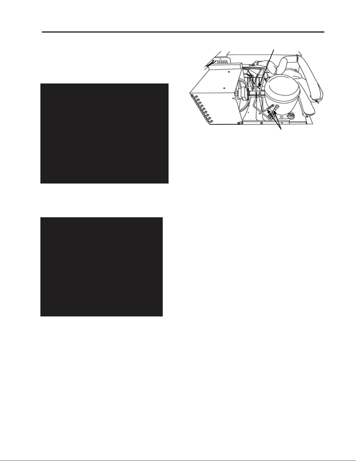
COMPRESSOR REPLACEMENT
1. Turn the main power switch in the machine
compartment to the off position
Evacuate the sealed system.
Cut Here
Slide Rail
Mounting Screw
2. Remove the high side slide rail mounting screw.
3. Slide the high side foward into the service position.
4. Clean and cut the refrigerant lines as close as
possible to the compressor stubs, leaving enough
length to install the replacement compressor.
NOTE: A new drier must be installed each time any
component of the system is opened or
replaced.
NOTE: The holding charge is your assurance that
the new compressor is dry and ready to
install. If you receive a replacement
compressor that shows no evidence of
holding charge when you remove the plugs,
return it.
Cut Here
5. Disconnect lead wires from compressor
terminals.
6. Remove the bolts from the compressor mounts.
Remove defective compressor from cabinet and
install rubber grommets on replacement
compressor.
7. Clean the compressor stubs with an abrasive
cloth such as grit cloth No. 23. Do not open the
compressor stubs.
8. Install the replacement compressor using the
mounting bolts previously removed.
9. Connect the compressor leads.
10.Transfer the process tube from the old
compressor. Connect the refrigerant tubing to
the compressor stubs using silfos on copper to
copper joints and silver solder and flux on steel
to copper joints.
11. Locate and remove old drier. Install new drier.
The new driver is installed in the following
manner:
a. Carefully bend the old drier and tubing away
from electrical parts.
b. Use steel wool or fine emery paper to clean
the capillary tube 3 inches from the original
joint. Also, clean the input tubing to the drier
of 3 inches from the original joint.
c. Use steel wool or fine emery paper to clean
both ends of the new drier. Use a knife or file
to score the capillary tube 1 inch from the
original joint. Use your finger to break the
connection.
d. Make an offset 1/2" from the end of the cap
tube to prevent it from penetrating too far into
the drier.
e. Cut the inlet tube of the replacement drier and
use pliers to snap off the scored end. Transfer
the process line to the new drier.
f. Install the new drier using silfos yoder tube
and the drier to compressor.
23 16021730 Rev. 0
Wicks
Main Power
Switch
Centigrade /
Fahrenheit
Switch
Figure 1
Defrost Water
Drain Pan Filter Drier
12.Evacuate, recharge and leak test the
system.
13.Test run the unit to check operation
14.Replace the machine compartment
cover.
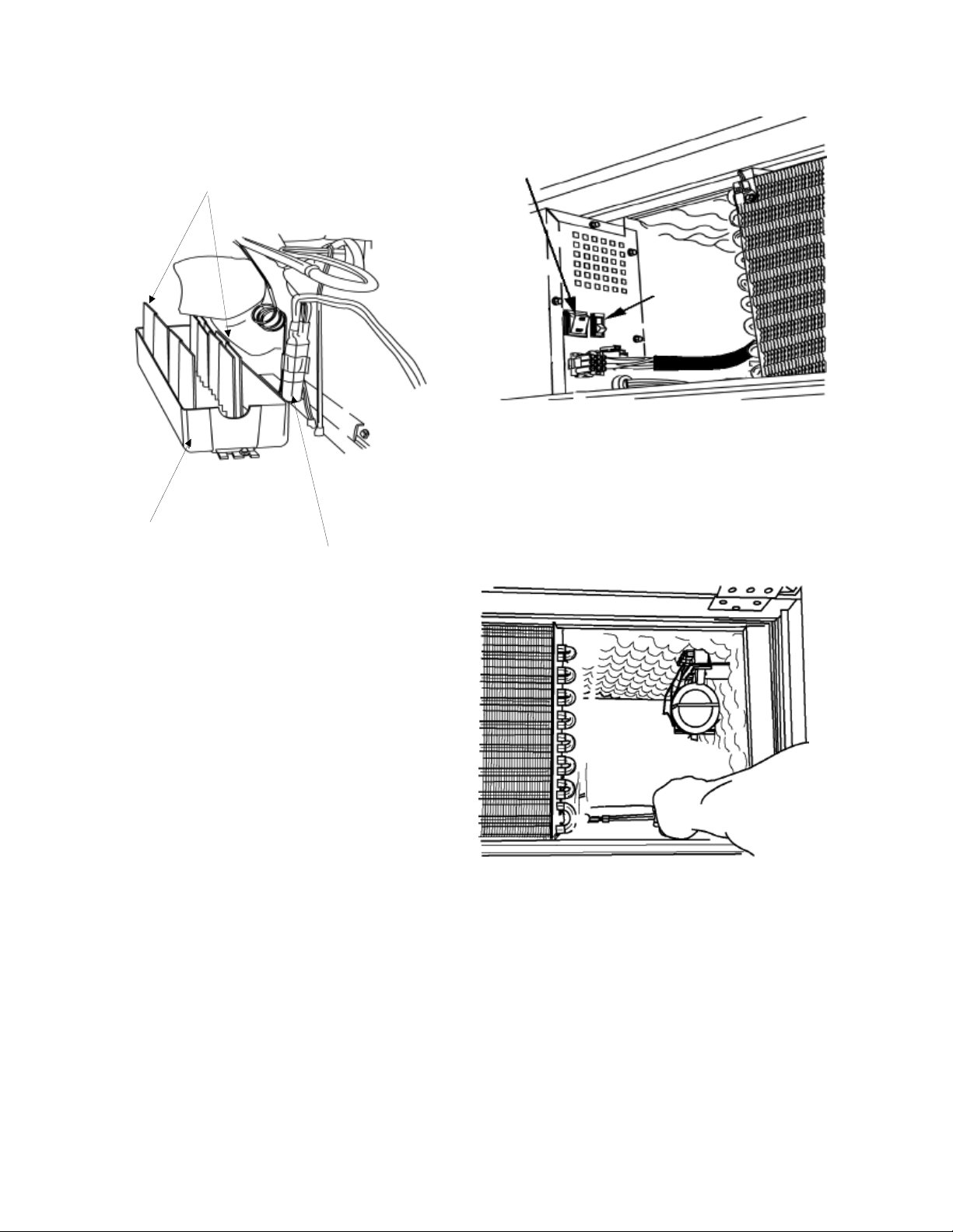
CONDENSER REPLACEMENT
The following general information explains how to
successfully replace the condenser for any model
covered in this manual.
1. Remove the Machine compartment access door.
2. Turn the main power switch in the machine com-
partment to the off position. (See figure 1)
3. Remove the high side slide rail mounting screw.
(See figure 2).
Figure 2
4. Slide the highside assembly forward into the service position.
(See figure 3).
16021730 Rev. 0 24
 Loading...