


 Loading...
J |
|
ELECTRICAL 8A - 1 |
|
ELECTRICAL
GROUP INDEX
Group
AUDIO SYSTEMS . . . . . . . . . . . . . . . . . . . . . . . . 8F BATTERY/STARTER/GENERATOR SERVICE . . . . 8B BATTERY/STARTING/CHARGING SYSTEMS
DIAGNOSTICS . . . . . . . . . . . . . . . . . . . . . . . . . 8A CHIME/BUZZER WARNING SYSTEMS . . . . . . . . 8U HORNS . . . . . . . . . . . . . . . . . . . . . . . . . . . . . . . . 8G IGNITION SYSTEMS . . . . . . . . . . . . . . . . . . . . . . 8D INSTRUMENT PANEL AND GAUGES . . . . . . . . . 8E LAMPS . . . . . . . . . . . . . . . . . . . . . . . . . . . . . . . . 8L OVERHEAD CONSOLE . . . . . . . . . . . . . . . . . . . . 8C POWER LOCKS . . . . . . . . . . . . . . . . . . . . . . . . . . 8P POWER MIRRORS . . . . . . . . . . . . . . . . . . . . . . . 8T
Group
POWER SEATS . . . . . . . . . . . . . . . . . . . . . . . . . . 8R POWER WINDOWS . . . . . . . . . . . . . . . . . . . . . . . 8S REAR WINDOW DEFOGGER . . . . . . . . . . . . . . . 8N RESTRAINT SYSTEMS . . . . . . . . . . . . . . . . . . . 8M TURN SIGNAL AND HAZARD WARNING
SYSTEMS . . . . . . . . . . . . . . . . . . . . . . . . . . . . . 8J VEHICLE SPEED CONTROL SYSTEM . . . . . . . . . 8H WIPER AND WASHER SYSTEMS . . . . . . . . . . . . 8K XJ WIRING DIAGRAMS-LEFT HAND DRIVE . . . 8W XJ WIRING DIAGRAMS-RIGHT HAND DRIVE . 8W YJ WIRING DIAGRAMS . . . . . . . . . . . . . . . . . . 8W
BATTERY/STARTING/CHARGING SYSTEMS DIAGNOSTICS
CONTENTS
|
page |
|
page |
BATTERY . . . . . . . . . . . . . . . . . . . . . . . . . . . . . |
. . 2 |
SPECIFICATIONS . . . . . . . . . . . . . . . . . . . . |
. . . . 23 |
CHARGING SYSTEM . . . . . . . . . . . . . . . . . . . . |
. 17 |
STARTING SYSTEM . . . . . . . . . . . . . . . . . . |
. . . . 11 |
IGNITION-OFF DRAW . . . . . . . . . . . . . . . . . . . |
. 10 |
USING ON-BOARD DIAGNOSTIC SYSTEM |
. . . . 22 |
GENERAL INFORMATION
The battery, starting, and charging systems operate with one another; therefore, they must be tested as a complete system. In order for the vehicle to start and charge properly, all of the components involved in these systems must perform within specifications.
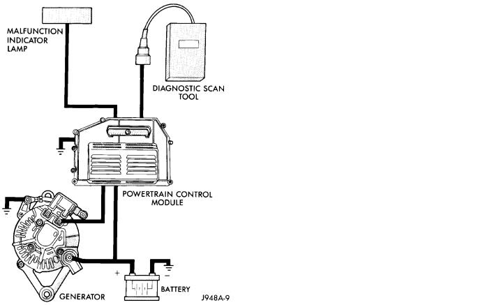
Group 8A covers battery, starting (Fig. 1) and charging (Fig. 2) system diagnostic procedures. These procedures include the most basic conventional diagnostic methods, to On-Board Diagnostics (OBD) built
into the Powertrain Control Module (PCM). Use of an induction milliamp ammeter, volt/ohmmeter, battery charger, carbon pile rheostat (load tester), and 12volt test lamp will be required.
All OBD-sensed systems are monitored by the PCM. Each monitored circuit is assigned a Diagnostic Trouble Code (DTC). The PCM will store a DTC in electronic memory for any failure it detects. See Using On-Board Diagnostic System in this group for more information.
8A - 2 BATTERY/STARTING/CHARGING SYSTEMS DIAGNOSTICS |
|
J |
|
Fig. 1 Starting System Components (Typical)
Fig. 2 Charging System Components (Typical)
BATTERY
GENERAL INFORMATION
The storage battery is a device used to store electrical energy potential in a chemical form. When an electrical load is applied to the battery terminals, an electrochemical reaction occurs within the battery. This reaction causes the battery to discharge electrical current.
The battery is made up of 6 individual cells that are connected in series. Each cell contains positively charged plate groups made of lead oxide, and negatively charged plate groups made of sponge lead. These dissimilar metal plates are submerged in a sulfuric acid and water solution called electrolyte.
As the battery discharges, a gradual chemical change takes place within each cell. The sulfuric acid in the electrolyte combines with the plate materials, causing both plates to change to lead sulfate. At the same time, oxygen from the positive plate material combines with hydrogen from the sulfuric acid, causing the electrolyte to become mainly water.
The chemical changes within the battery are caused by movement of excess or free electrons between the positive and negative plate groups. This
movement of electrons produces a flow of electrical current through the load device attached to the battery terminals.
As the plate materials become more similar chemically, and the electrolyte becomes less acid, the voltage potential of each cell is reduced. However, by charging the battery with a voltage higher than that of the battery, the process is reversed.
Charging the battery gradually changes the sulfated lead plates back into sponge lead and lead oxide, and the water back into sulfuric acid. This action restores the difference in electron charges deposited on the plates, and the voltage potential of the battery cells.
For a battery to remain useful, it must be able to produce high-amperage current over an extended period. A battery must also be able to accept a charge, so that its voltage potential may be restored.
In addition to producing and storing electrical energy, the battery serves as a capacitor or voltage stabilizer for the vehicle electrical system. It absorbs abnormal or transient voltages caused by switching of any of the vehicle's electrical components.
The battery is vented to release excess gas that is created when the battery is being charged or dis-
J |
|
BATTERY/STARTING/CHARGING SYSTEMS DIAGNOSTICS 8A - 3 |
|
charged. However, even with these vents, hydrogen gas can collect in or around the battery. If hydrogen gas is exposed to flame or sparks, it can ignite.
If the electrolyte level is low, the battery could arc internally and explode. If the battery is equipped with removable cell caps, add distilled water whenever the electrolyte level is below the top of the plates. If the battery cell caps cannot be removed, the battery must be replaced when the electrolyte level is low.
WARNING: DO NOT ATTEMPT TO ASSIST BOOST, CHARGE, OR TEST BATTERY WHEN ELECTROLYTE LEVEL IS BELOW THE TOP OF THE PLATES. PERSONAL INJURY MAY OCCUR.
BATTERY RATINGS
Currently, there are 2 commonly accepted methods for rating and comparing battery performance. These ratings are called Cold Cranking Amperage (CCA), and Reserve Capacity (RC). Be certain that a replacement battery has CCA and RC ratings that equal or exceed the original equipment specification for the vehicle being serviced. See Battery Classifications and Ratings charts in Specifications at the back of this group.
COLD CRANKING AMPERAGE
The Cold Cranking Amperage (CCA) rating specifies how much current (in amperes) the battery can deliver for 30 seconds at -17.7°C (0°F). Terminal voltage must not fall below 7.2 volts during or after the 30 second discharge. The CCA required is generally higher as engine displacement increases, depending also upon the starter current draw requirements.
RESERVE CAPACITY
The Reserve Capacity (RC) rating specifies the time (in minutes) it takes for battery terminal voltage to fall below 10.2 volts at a discharge rate of 25 amps. RC is determined with the battery fullycharged at 26.7°C (80°F). This rating estimates how long the battery might last after a charging system failure, under minimum electrical load.
DIAGNOSIS
The battery must be completely charged and the top, posts, and terminal clamps should be properly cleaned before diagnostic procedures are performed. Refer to Group 8B - Battery/Starter/Generator Service for more information.
The condition of a battery is determined by two criteria:
(1) State-Of-Charge This can be determined by viewing the built-in test indicator, by checking specific gravity of the electrolyte (hydrometer test), or by checking battery voltage (open circuit voltage test).
(2) Cranking Capacity This can be determined by performing a battery load test, which measures the ability of the battery to supply high-amperage current.
If the battery has a built-in test indicator, use this test first. If it has no test indicator, but has removable cell caps, perform the hydrometer test first. If cell caps are not removable, or a hydrometer is not available, perform the open circuit voltage test first.
The battery must be charged before proceeding with a load test if:
²the built-in test indicator has a black or dark color visible
²the temperature corrected specific gravity is less than 1.235
²the open circuit voltage is less than 12.4 volts.
A battery that will not accept a charge is faulty and further testing is not required. A battery that is fully-charged, but does not pass the load test is faulty and must be replaced.
Completely discharged batteries may take several hours to accept a charge. See Charging Completely Discharged Battery.
A battery is fully-charged when:
²all cells are gassing freely during charging
²a green color is visible in the sight glass of the built-in test indicator
²three corrected specific gravity tests, taken at 1-hour intervals, indicate no increase in specific gravity
²open circuit voltage is 12.4 volts or greater.
ABNORMAL BATTERY DISCHARGING
Any of the following conditions can result in abnormal battery discharging:
(1)Corroded battery posts and terminals.
(2)Loose or worn generator drive belt.
(3)Electrical loads that exceed the output of the charging system, possibly due to equipment installed after manufacture or repeated short trip use.
(4)Slow driving speeds (heavy traffic conditions) or prolonged idling with high-amperage draw systems in use.
(5)Faulty circuit or component causing excessive ignition-off draw. See Ignition-Off Draw in this group for diagnosis.
(6)Faulty charging system.
(7)Faulty or incorrect battery.
BUILT-IN TEST INDICATOR
A test indicator (hydrometer) built into the top of the battery case, provides visual information for battery testing (Fig. 1). It is important when using the test indicator that the battery be level and have a clean sight glass to see correct indications. Additional light may be required to view indicator.

8A - 4 BATTERY/STARTING/CHARGING SYSTEMS DIAGNOSTICS |
|
J |
|
BATTERY DIAGNOSIS
J |
|
BATTERY/STARTING/CHARGING SYSTEMS DIAGNOSTICS 8A - 5 |
|
WARNING: DO NOT USE OPEN FLAME AS A
SOURCE OF ADDITIONAL LIGHT FOR VIEWING
TEST INDICATOR. EXPLOSIVE HYDROGEN GAS
MAY BE PRESENT IN THE AREA SURROUNDING
BATTERY.
Fig. 1 Built-In Test Indicator
Like a hydrometer, the built-in test indicator measures the specific gravity of the electrolyte. Specific gravity will indicate battery state-of-charge. However, the test indicator will not indicate cranking capacity of the battery. See Load Test in this group for more information.
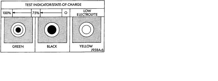
Look into the sight glass and note the color of the indicator (Fig. 2). Refer to the following description, as the color indicates:
GREENÐindicates 75% to 100% state-of-charge. The battery is adequately charged for further testing or return to use. If the vehicle will not crank for a minimum of 15 seconds with a fully-charged bat-
tery, perform Load Test.
BLACK OR DARKÐindicates 0% to 75% state-of- charge.
The battery is inadequately charged and must be charged until green indicator (Fig. 2) is visible in sight glass (12.4 volts or more) before the battery is tested further or returned to use. See Abnormal Battery Discharging in this group to diagnose cause of discharged condition.
YELLOW OR BRIGHTÐindicates low electrolyte level.
The electrolyte level in the battery is below test indicator (Fig. 2). A maintenance-free battery with nonremovable cell caps must be replaced if electrolyte level is low. Water can be added to a low-mainte- nance battery with removable cell caps. A low electrolyte level may be caused by an over-charging condition. See Charging System in this group to diagnose an over-charging condition.
WARNING: DO NOT ATTEMPT TO CHARGE, TEST, OR ASSIST BOOST BATTERY WHEN YELLOW OR BRIGHT COLOR IS VISIBLE IN SIGHT GLASS OF TEST INDICATOR. LOW ELECTROLYTE LEVEL CAN ALLOW BATTERY TO ARC INTERNALLY AND EXPLODE. PERSONAL INJURY MAY OCCUR.
Fig. 2 Built-In Test Indicator Sight Glass
HYDROMETER TEST
The hydrometer test reveals the battery state-of- charge by measuring the specific gravity of the electrolyte. This test cannot be performed on batteries with non-removable cell caps. If battery has non-re- movable cell caps, see Built-In Test Indicator or Open Circuit Voltage Test.
Specific gravity is a comparison of the density of the electrolyte to the density of pure water. Pure water has a specific gravity of 1.000, and sulfuric acid has a specific gravity of 1.835. Sulfuric acid makes up approximately 35% of the electrolyte by weight, or 24% by volume.
In a fully-charged battery the electrolyte will have a temperature corrected specific gravity of 1.260 to 1.290. However, a specific gravity of 1.235 or above is satisfactory for battery load testing and/or return to service.
Before testing, visually inspect battery for any damage (cracked case or cover, loose posts, etc.) that would cause the battery to be faulty. Then remove cell caps and check electrolyte level. Add distilled water if electrolyte level is below the top of the battery plates.
To use the hydrometer correctly, hold it with the top surface of the electrolyte at eye level. Refer to the hydrometer manufacturer's instructions for correct use of hydrometer. Remove only enough electrolyte from the battery so the float is off the bottom of the hydrometer barrel with pressure on the bulb released.
Exercise care when inserting the tip of the hydrometer into a cell to avoid damaging the plate separators. Damaged plate separators can cause premature battery failure.
Hydrometer floats are generally calibrated to indicate the specific gravity correctly only at 26.7°C (80°F). When testing the specific gravity at any other temperature, a correction factor is required.
The correction factor is approximately a specific gravity value of 0.004, referred to as 4 points of specific gravity. For each 5.5°C above 26.7°C (10°F above 80°F), add 4 points. For each 5.5°C below 26.7°C (10°F below 80°F), subtract 4 points. Always correct
8A - 6 BATTERY/STARTING/CHARGING SYSTEMS DIAGNOSTICS |
|
J |
|
the specific gravity for temperature variation. Test the specific gravity of the electrolyte in each battery cell.
Example: A battery is tested at -12.2°C (10°F) and has a specific gravity of 1.240. Determine the actual specific gravity as follows:
(1)Determine the number of degrees above or below 26.7°C (80°F):
26.6°C - -12.2°C = 38.8°C (80°F - 10°F = 70°F)
(2)Divide the result from step 1 by 5.5 (10): 38.8°C/5.5 = 7 (70°F/10 = 7)
(3)Multiply the result from step 2 by the temperature correction factor (0.004):
7 x 0.004 = 0.028
(4)The temperature at testing was below 26.7°C (80°F); therefore, the temperature correction is subtracted:
1.240 - 0.028 = 1.212
The corrected specific gravity of the battery in this example is 1.212.
If the specific gravity of all cells is above 1.235, but variation between cells is more than 50 points (0.050), the battery should be replaced.
If the specific gravity of one or more cells is less than 1.235, charge the battery at a rate of approximately 5 amperes. Continue charging until 3 consecutive specific gravity tests, taken at 1-hour intervals, are constant. If the cell specific gravity variation is more than 50 points (0.050) at the end of the charge period, replace the battery.
When the specific gravity of all cells is above 1.235, and cell variation is less than 50 points (0.050), the battery may be load tested.
OPEN CIRCUIT VOLTAGE TEST
A battery open circuit voltage (no load) test will show state-of-charge of a battery. This test can be used in place of the hydrometer test if a hydrometer is not available, or for maintenance-free batteries with non-removable cell caps.
Before proceeding with this test or load test, completely charge battery as described in Battery Charging in this group.
Test battery open circuit voltage as follows:
(1)Before measuring open circuit voltage the surface charge must be removed from the battery. Turn headlamps on for 15 seconds, then allow up to 5 minutes for voltage to stabilize.
(2)Remove both battery cables, negative first.
(3)Using a voltmeter connected to the battery posts (refer to instructions provided with voltmeter) measure open circuit voltage (Fig. 3).
See Open Circuit Voltage chart. This voltage reading will indicate state-of-charge, but will not reveal cranking capacity. If a battery has an open circuit voltage reading of 12.4 volts or greater, it may be load tested. A battery that will not endure a load test is faulty and must be replaced.
OPEN CIRCUIT VOLTAGE
Fig. 3 Testing Open Circuit Voltage
LOAD TEST
A battery load test will verify battery cranking capacity. The test is based on the Cold Cranking Amperage (CCA) rating of the battery. See Battery Classifications and Ratings chart in Specifications, at the back of this group.
WARNING: IF BATTERY SHOWS SIGNS OF FREEZING, LEAKING, LOOSE POSTS, OR LOW ELECTROLYTE LEVEL, DO NOT LOAD TEST. PERSONAL INJURY AND/OR VEHICLE DAMAGE MAY RESULT.
Before performing load test, the battery must be FULLY-CHARGED.
(1)Remove both battery cables, negative first. Battery top and posts should be clean.
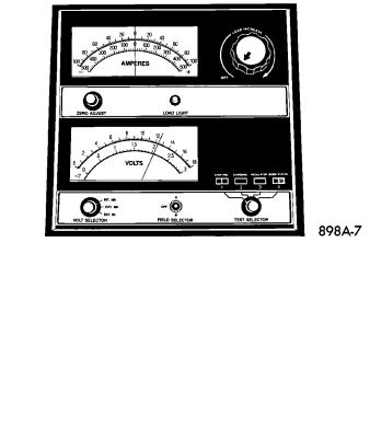
(2)Connect a suitable volt-ammeter-load tester (Fig. 4) to the battery posts (Fig. 5). Refer to operating instructions provided with the tester being used. Check the open circuit voltage (no load) of the battery. Open circuit voltage must be 12.4 volts or greater.
(3)Rotate the load control knob (carbon pile rheostat) to apply a 300 amp load for 15 seconds, then return the control knob to OFF (Fig. 6). This will remove the surface charge from the battery.
(4)Allow the battery to stabilize to open circuit voltage. It may take up to 5 minutes for voltage to stabilize.
J |
|
BATTERY/STARTING/CHARGING SYSTEMS DIAGNOSTICS 8A - 7 |
|
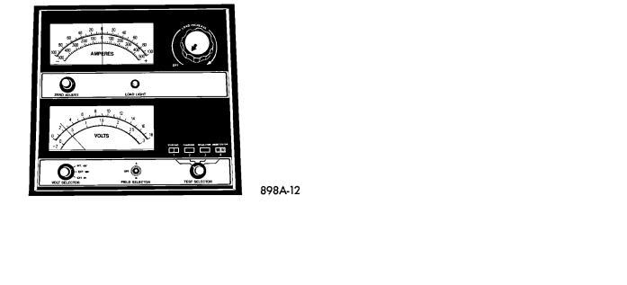
Fig. 4 Volt-Amps-Load Tester (Typical) |
Fig. 7 Load 50% CCA Rating - Note Voltage |
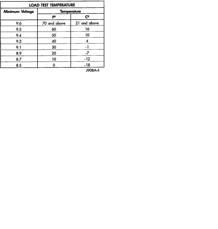
test, the battery will be somewhat warmer. See Load Test Temperature chart for proper loaded voltage reading.
(7) If the voltmeter reading falls below 9.6 volts, at a minimum battery temperature of 21°C (70°F), replace the battery.
Fig. 5 Volt-Ammeter-Load Tester Connections
Fig. 6 Remove Surface Charge from Battery
(5)Rotate the load control knob to maintain a load equal to 50% of CCA rating (Fig. 7). After 15 seconds, record the loaded voltage reading, then return the load control knob to OFF.
(6)Voltage drop will vary with battery temperature at the time of the load test. Battery temperature can be estimated by the ambient temperature over the past several hours. If the battery has been charged, boosted, or loaded a few minutes prior to
BATTERY CHARGING
A battery is fully-charged when:
²all cells are gassing freely during charging
²a green color is visible in sight glass of built-in test indicator
²three corrected specific gravity tests, taken at 1-hour intervals, indicate no increase in specific gravity
²open circuit voltage is 12.4 volts or above.
WARNING: DO NOT ASSIST BOOST OR CHARGE A BATTERY THAT HAS LOW ELECTROLYTE LEVEL OR IS FROZEN. BATTERY MAY ARC INTERNALLY AND EXPLODE.
WARNING: EXPLOSIVE HYDROGEN GAS FORMS IN AND AROUND BATTERY. DO NOT SMOKE, USE FLAME, OR CREATE SPARKS NEAR BATTERY.
8A - 8 BATTERY/STARTING/CHARGING SYSTEMS DIAGNOSTICS |
|
J |
|
WARNING: POISONOUS AND CAUSTIC. BATTERY CONTAINS SULFURIC ACID. AVOID CONTACT WITH SKIN, EYES, OR CLOTHING. IN EVENT OF CONTACT, FLUSH WITH WATER AND CALL PHYSICIAN IMMEDIATELY. KEEP OUT OF REACH OF CHILDREN.
CAUTION: Always disconnect the battery negative cable before charging battery to avoid damage to electrical system components. Do not exceed 16.0 volts while charging battery.
Battery electrolyte will bubble inside battery case during normal battery charging. If the electrolyte boils, or is discharged from the vent holes while charging, immediately reduce charging rate or turn OFF charger and evaluate battery condition.
Battery should not be hot to the touch. If the battery feels hot to the touch, turn OFF charger and let battery cool before continuing charging operation.
Some battery chargers are equipped with polarity sensing circuitry. This circuitry protects the charger and/or battery from being damaged if improperly connected.
If the battery state-of-charge is too low for the polarity sensing circuitry to detect, the charger will not operate. This makes it appear that the battery will not accept charging current. Refer to instructions provided with the battery charger being used to bypass the polarity sensing circuitry.
BATTERY CHARGING TIME TABLE
After the battery has been charged to 12.4 volts or greater, perform a load test to determine cranking capacity. If the battery will endure a load test, return the battery to use. If the battery will not endure a load test, it must be replaced.
Clean and inspect battery holddowns, tray, terminals, posts, and top before completing service. Refer to Group 8B - Battery/Starter/Generator Service for more information.
CHARGING TIME REQUIRED
The time required to charge a battery will vary, depending upon the following factors:
(1) Battery CapacityÐA completely discharged heavy-duty battery requires twice the recharging time of a small capacity battery.
WARNING: NEVER EXCEED 20 AMPS WHEN CHARGING A COLD (-1°C/30°F) BATTERY. PERSONAL INJURY MAY RESULT.
(2)TemperatureÐA longer time will be needed to charge a battery at -18°C (0°F) than at 27°C (80°F). When a fast charger is connected to a cold battery, current accepted by the battery will be very low at first. As the battery warms, it will accept a higher charging current rate.
(3)Charger CapacityÐA charger that supplies only 5 amperes will require a longer charging time. A charger that supplies 20 amperes or more requires a shorter charging time.
(4)State-Of-ChargeÐA completely discharged battery requires more charging time than a partially discharged battery. Electrolyte is nearly pure water in a completely discharged battery. At first, the charging current (amperage) will be low. As the battery charges, the specific gravity of the electrolyte will gradually rise.
CHARGING COMPLETELY DISCHARGED BATTERY
The following procedure should be used to recharge a completely discharged battery. Unless this procedure is properly followed, a good battery may be needlessly replaced.
(1) Measure voltage at battery posts with a voltmeter, accurate to 1/10 (0.10) volt (Fig. 8). If the reading is below 10 volts, the charge current will be low. It could take some time before the battery accepts a current greater than a few milliamperes. Such low current may not be detectable on ammeters built into many chargers.
Fig. 8 Voltmeter Accurate to 1/10 Volt Connected
(2) Disconnect battery negative cable. Connect charger leads. Some battery chargers are equipped
Loading...