

User Guide
2014
Grand Cherokee
Includes SRT

If you are the first registered retail owner of
your vehicle, you may obtain a complimentary
printed copy of the Owner’s Manual, Navigation/
Uconnect® Manuals or Warranty Booklet by calling
1-877-426-5337 (U.S.) or 1-800-387-1143 (Canada)
or by contacting your dealer.
The driver’s primary responsibility is the safe operation of the vehicle.
Driving while distracted can result in loss of vehicle control, resulting in
a collision and personal injury. Chrysler Group LLC strongly recommends
that the driver use extreme caution when using any device or feature
that may take their attention o the road. Use of any electrical devices
such as cell phones, computers, portable radios, vehicle navigation or
other devices by the driver while the vehicle is moving is dangerous and
could lead to a serious collision. Texting while driving is also dangerous
and should never be done while the vehicle is moving. If you find yourself
unable to devote your full attention to vehicle operation, pull o the
road to a safe location and stop your vehicle. Some States or Provinces
prohibit the use of cellular telephones or texting while driving. It is
always the driver’s responsibility to comply with all local laws.
Important:
This User Guide is intended to familiarize you with the important features
of your vehicle. The DVD enclosed contains your Owner’s Manual,
Navigation/Uconnect® Manuals, Warranty Booklets, Tire Warranty and
Roadside Assistance (new vehicles purchased in the U.S.) or Roadside
Assistance (new vehicles purchased in Canada) in electronic format.
We hope you find it useful. Replacement DVD kits may be purchased by
visiting www.techauthority.com. Jeep® is a registered trademark of
Chrysler Group LLC. © 2014 Chrysler Group LLC.

TABLE OF CONTENTS
INTRODUCTION/WELCOME
WELCOME FROM CHRYSLER
GROUP LLC ..................3
CONTROLS AT A GLANCE
DRIVER COCKPIT ...............6
INSTRUMENT CLUSTER ..........8
GETTING STARTED
KEYFOB ...................10
REMOTE START ...............10
KEYLESS ENTER-N-GO™ .........11
VEHICLE SECURITY ALARM .......15
SEATBELT ..................15
SUPPLEMENTAL RESTRAINT SYSTEM
(SRS) — AIR BAGS ............16
CHILD RESTRAINTS ............17
FRONT SEATS ................ 21
REAR SEATS .................24
HEATED/VENTILATED SEATS ....... 24
HEATED STEERING WHEEL ....... 26
TILT/TELESCOPING STEERING
COLUMN ...................27
OPERATING YOUR VEHICLE
ENGINE BREAK-IN
RECOMMENDATIONS ...........28
HEADLIGHT SWITCH ............29
TURN SIGNAL/WIPER/WASHER/HIGH
BEAM LEVER ................ 30
AUTOMATIC DIMMING MIRRORS ....32
SPEED CONTROL ..............32
ADAPTIVE CRUISE CONTROL (ACC) . . . 34
FORWARD COLLISION WARNING (FCW)
WITHMITIGATION .............36
ELECTRONIC SHIFTER ........... 38
PADDLE SHIFT MODE ...........39
FUEL ECONOMY (ECO) MODE ...... 39
AUTOMATIC CLIMATE CONTROLS
WITH TOUCHSCREEN ...........40
PARKSENSE
PARK ASSIST ................ 42
PARKVIEW
BLIND SPOT MONITORING ........ 44
POWER SUNROOF .............44
WIND BUFFETING ............. 47
®
FRONT AND REAR
®
REAR BACK-UP CAMERA . 43
ELECTRONICS
YOUR VEHICLE'S SOUND SYSTEM . . . 48
IDENTIFYING YOUR RADIO ........50
®
Uconnect
Uconnect
Uconnect
Uconnect
ACCESS ............. 51
®
5.0 ................65
®
8.4A ............... 73
®
8.4AN ..............93
STEERING WHEEL AUDIO CONTROLS . . 114
ELECTRONIC VEHICLE INFORMATION
CENTER (EVIC) .............. 114
PROGRAMMABLE FEATURES ...... 115
UNIVERSAL GARAGE DOOR OPENER
(HomeLink
POWER INVERTER ............119
POWER OUTLETS .............120
®
) ................117
OFF-ROAD CAPABILITIES
(4WD OPERATION)
QUADRA-TRAC I®FOUR-WHEEL
DRIVE .................... 122
QUADRA-TRAC II
FOUR-WHEEL DRIVE .......... 122
SELEC-TERRAIN™ ............124
QUADRA-LIFT™ .............. 125
HILL START ASSIST/HILL DESCENT
CONTROL/SELEC SPEED CONTROL . . 127
®
/QUADRA-DRIVE II
®
UTILITY
TRAILER TOWING WEIGHTS (MAXIMUM
TRAILER WEIGHT RATINGS) ...... 128
RECREATIONAL TOWING (BEHIND
MOTORHOME, ETC.) ...........132
SRT
PADDLE SHIFT MODE ..........136
SELEC-TRACK™ ..............137
SRT PERFORMANCE FEATURES ....138
SUMMER/THREE-SEASON TIRES . . . 141
DIESEL
DIESEL ENGINE BREAK-IN
RECOMMENDATIONS ..........142
DIESEL ENGINE STARTING
PROCEDURES ...............142
DIESEL FUEL FILTERS/WATER
SEPARATOR ................144
EXHAUST REGENERATION ....... 145
DIESEL EXHAUST FLUID ........146
WHAT TO DO IN EMERGENCIES
ROADSIDE ASSISTANCE ......... 150
INSTRUMENT CLUSTER WARNING
LIGHTS ................... 150
IF YOUR ENGINE OVERHEATS .....158
JACKING AND TIRE CHANGING .... 158
BATTERY LOCATION ...........165
JUMP-STARTING .............165
EMERGENCY TOW HOOKS ....... 167
MANUAL PARK RELEASE 8-SPEED . . 168
TOWING A DISABLED VEHICLE ....169
EVENT DATA RECORDER (EDR) .... 170
CAP-LESS FUEL FILL FUNNEL .....170

TABLE OF CONTENTS
MAINTAINING YOUR VEHICLE
OPENING THE HOOD ........... 171
ADDING FUEL ...............172
ENGINE COMPARTMENT ........ 173
FLUIDS AND CAPACITIES –
GASOLINE VERSION ...........177
FLUIDS AND CAPACITIES –
DIESEL VERSION .............181
MAINTENANCE SCHEDULE —
GASOLINE ENGINE ............ 184
MAINTENANCE SCHEDULE —
DIESEL ENGINE ..............194
FUSES .................... 201
TIRE PRESSURES ............. 204
WHEEL AND WHEEL TRIM CARE . . . 204
EXTERIOR BULBS ............ 205
CONSUMER ASSISTANCE
CHRYSLER GROUP LLC CUSTOMER
CENTER ..................206
CHRYSLER CANADA INC. CUSTOMER
CENTER ..................206
ASSISTANCE FOR THE HEARING
IMPAIRED .................206
PUBLICATIONS ORDERING ....... 206
REPORTING SAFETY DEFECTS IN
THEUNITEDSTATES ........... 207
MOPAR® ACCESSORIES
AUTHENTIC ACCESSORIES BY
MOPAR®...................208
FAQ’s
FREQUENTLY ASKED QUESTIONS . . . 209
INDEX
...................211
2

INTRODUCTION/WELCOME
WELCOME FROM CHRYSLER GROUP LLC
Congratulations on selecting your new Chrysler Group LLC vehicle. Be assured that it
represents precision workmanship, distinctive styling, and high quality - all essentials that are traditional to our vehicles.
Your new Chrysler Group LLC vehicle has characteristics to enhance the driver's
control under some driving conditions. These are to assist the driver and are never a
substitute for attentive driving. They can never take the driver's place. Always drive
carefully.
Your new vehicle has many features for the comfort and convenience of you and your
passengers. Some of these should not be used when driving because they take your
eyes from the road or your attention from driving. Never text while driving or take your
eyes more than momentarily off the road.
This guide illustrates and describes the operation of features and equipment that are
either standard or optional on this vehicle. This guide may also include a description
of features and equipment that are no longer available or were not ordered on this
vehicle. Please disregard any features and equipment described in this guide that are
not available on this vehicle. Chrysler Group LLC reserves the right to make changes
in design and specifications and/or make additions to or improvements to its
products without imposing any obligation upon itself to install them on products
previously manufactured.
This User Guide has been prepared to help you quickly become acquainted with the
important features of your vehicle. It contains most things you will need to operate
and maintain the vehicle, including emergency information.
The DVD includes a computer application containing detailed owner's information
which can be viewed on a personal computer or MAC computer. The multimedia DVD
also includes videos which can be played on any standard DVD player (including the
Uconnect
on the back of the DVD sleeve.
For complete owner information, refer to your Owner's Manual on the DVD in the owner’s
kit provided at the time of new vehicle purchase. For your convenience, the information
contained on the DVD may also be printed and saved for future reference.
Chrysler Group LLC is committed to protecting our environment and natural resources. By converting from paper to electronic delivery for the majority of the user
information for your vehicle, together we greatly reduce the demand for tree-based
products and lessen the stress on our environment.
®
Touchscreen Radios). Additional DVD operational information is located
3

INTRODUCTION/WELCOME
VEHICLES SOLD IN CANADA
With respect to any vehicles sold in Canada, the name Chrysler Group LLC shall be
deemed to be deleted and the name Chrysler Canada Inc. used in substitution.
WARNING!
• Pedals that cannot move freely can cause loss of vehicle control and increase
the risk of serious personal injury.
• Always make sure that objects cannot fall into the driver foot well while the
vehicle is moving. Objects can become trapped under the brake pedal and
accelerator pedal causing a loss of vehicle control.
• Failure to properly follow floor mat installation or mounting can cause interference with the brake pedal and accelerator pedal operation causing loss of
control of the vehicle.
• Never leave children alone in a vehicle, or with access to an unlocked vehicle.
Allowing children to be in a vehicle unattended is dangerous for a number of
reasons. A child or others could be seriously or fatally injured. Children should
be warned not to touch the parking brake, brake pedal or the shift lever/gear
selector.
• Never use the ‘PARK’ position as a substitute for the parking brake. Always
apply the parking brake fully when parked to guard against vehicle movement
and possible injury or damage.
• Do not leave the key fob in or near the vehicle, or in a location accessible to
children. A child could operate power windows, other controls, or move the
vehicle.
• Refer to your Owner's Manual on the DVD for further details.
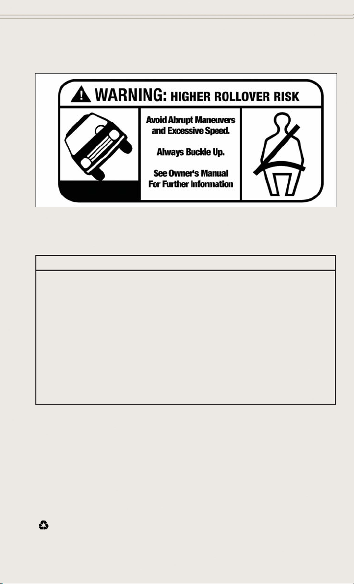
Rollover Warning
• Utility vehicles have a significantly higher rollover rate than other types of
vehicles. This vehicle has a higher ground clearance and a higher center of gravity
than many passenger cars. It is capable of performing better in a wide variety of
off-road applications.
• Driven in an unsafe manner, all vehicles can go out of control. Because of the
higher center of gravity, if this vehicle is out of control it may roll over when some
other vehicles may not.
• Do not attempt sharp turns, abrupt maneuvers, or other unsafe driving actions that
can cause loss of vehicle control. Failure to operate this vehicle safely may result
in a collision, rollover of the vehicle, and severe or fatal injury. Drive carefully.
4
INTRODUCTION/WELCOME
• Failure to use the driver and passenger seat belts provided is a major cause of
severe or fatal injury. In a rollover crash, an unbelted person is significantly more
likely to die than a person wearing a seat belt. Always buckle up.
WARNING!
• Pedals that cannot move freely can cause loss of vehicle control and increase
the risk of serious personal injury.
• Always make sure that objects cannot fall into the driver foot well while the
vehicle is moving. Objects can become trapped under the brake pedal and
accelerator pedal causing a loss of vehicle control.
• Failure to properly follow floor mat installation or mounting can cause interference with the brake pedal and accelerator pedal operation causing loss of
control of the vehicle.
• Refer to your Owner's Manual on the DVD for further details.
• Never use the ‘PARK’ position as a substitute for the parking brake. Always
apply the parking brake fully when parked to guard against vehicle movement
and possible injury or damage.
USE OF AFTERMARKET PRODUCTS (ELECTRONICS)
The use of aftermarket devices including cell phones, MP3 players, GPS systems, or
chargers may affect the performance of on-board wireless features including Keyless
Enter-N-Go™ and Remote Start range. If you are experiencing difficulties with any of
your wireless features, try disconnecting your aftermarket devices to see if the
situation improves. If your symptoms persist, please see an authorized dealer.
CHRYSLER, DODGE, JEEP, RAM TRUCK, SRT, ATF+4, MOPAR and Uconnect are
registered trademarks of Chrysler Group LLC.
COPYRIGHT ©2014 CHRYSLER GROUP LLC
5
CONTROLS AT A GLANCE
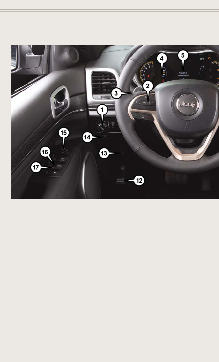
DRIVER COCKPIT
1. Headlight Switch pg. 29
2. Electronic Vehicle Information Center (EVIC) Controls pg. 114
3. Turn Signal/Wiper/Washer/High Beams Lever (behind steering wheel) pg. 30
4. Instrument Cluster pg. 9
5. Electronic Vehicle Information Center (EVIC) Display pg. 8
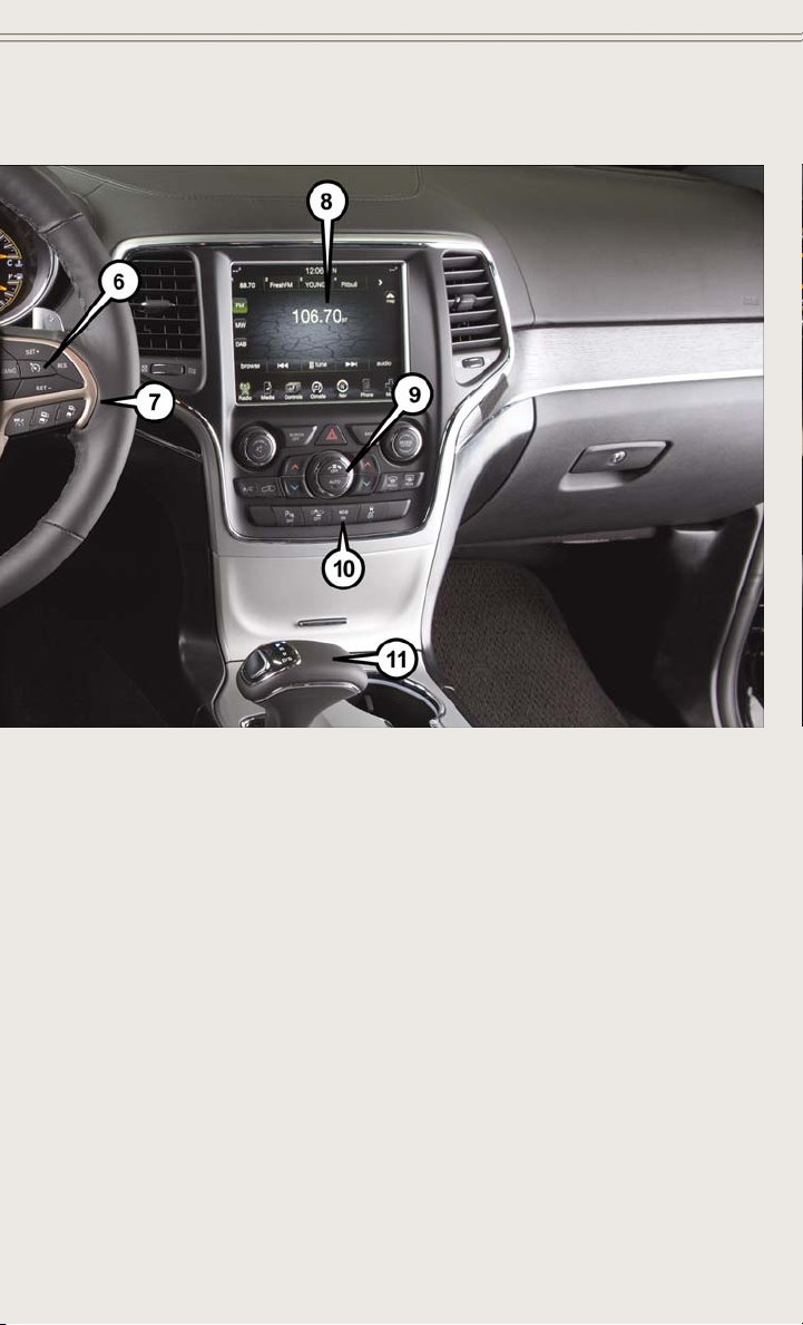
6. Speed Control pg. 32
7. Engine Start/Stop Button (behind steering wheel) pg. 13
8. Audio System (Touchscreen Radio Shown) pg. 48
6
CONTROLS AT A GLANCE
9. Automatic Climate Controls pg. 40
10. Switch Panel
®
• ParkSense
• ECO On pg. 39
• Electronic Stability Control (ESC) OFF pg. 153
11. Electronic Shifter pg. 38
12. Emergency Brake Pedal
13. Hood Release pg. 171
14. Fuel Door Release Button pg. 172
15. Power Mirrors
16. Power Windows
17. Power Window Locks
pg. 42
7
CONTROLS AT A GLANCE
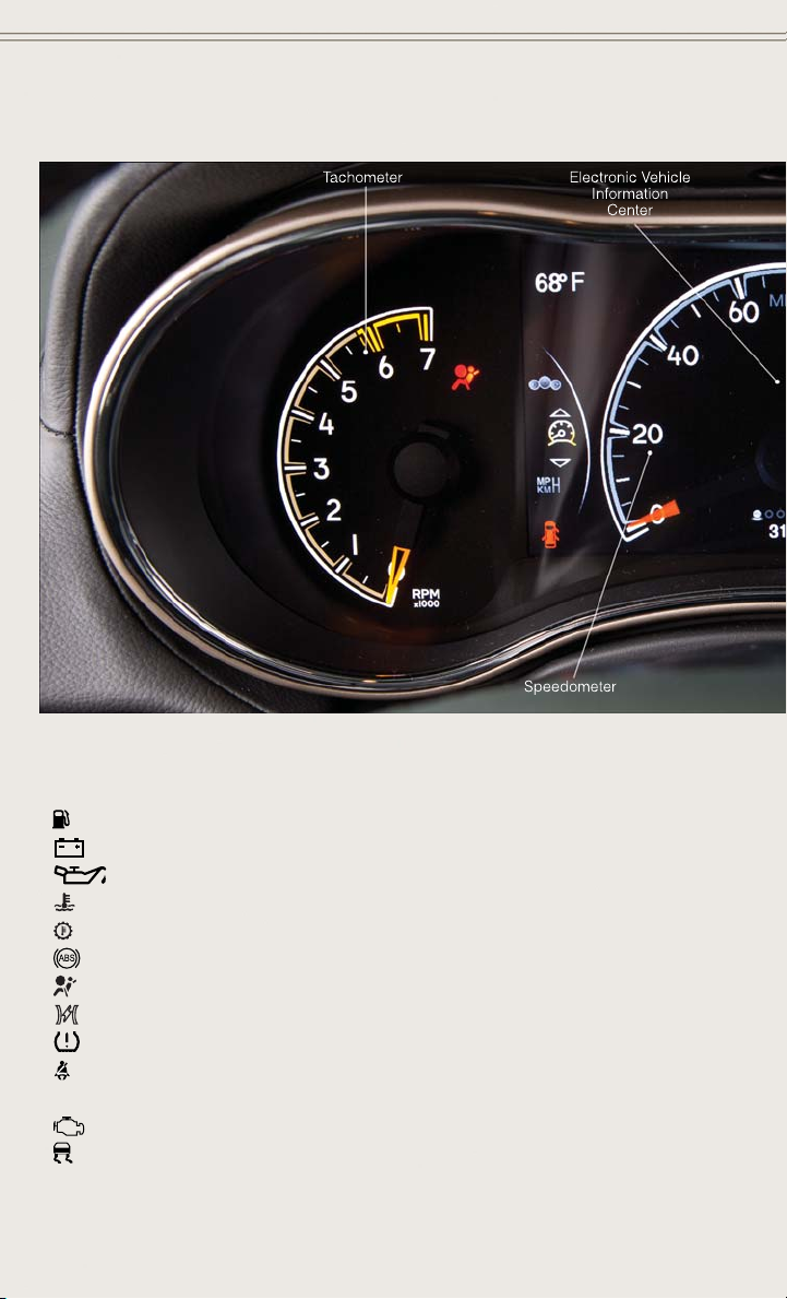
INSTRUMENT CLUSTER
Warning Lights
- Low Fuel Warning Light
- Charging System Light **
- Oil Pressure Warning Light **
- Engine Temperature Warning Light
- Transmission Temperature Warning Light
- Anti-Lock Brake (ABS) Light **
- Air Bag Warning Light **
- Electronic Throttle Control (ETC) Light
- Tire Pressure Monitoring System (TPMS) Light
- Seat Belt Reminder Light
BRAKE
(See page 150 for more information.)
8
- Brake Warning Light **
- Malfunction Indicator Light (MIL) **
-
Electronic Stability Control (ESC) Activation/Malfunction Indicator Light *
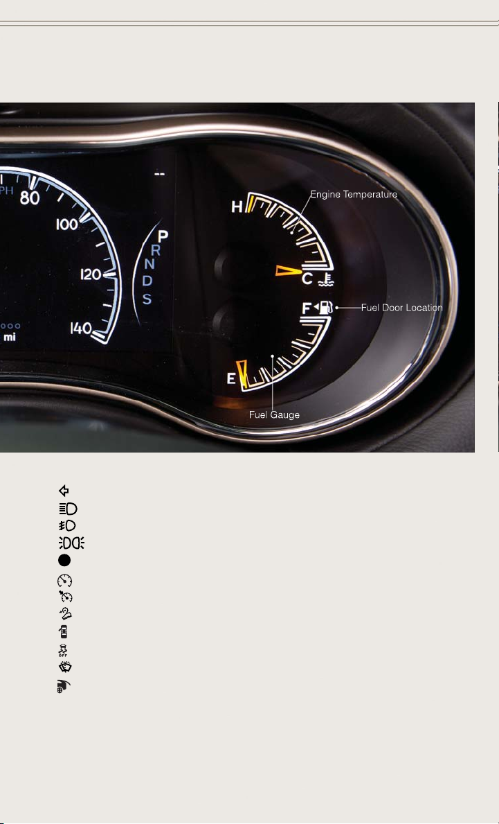
CONTROLS AT A GLANCE
Indicators
-Turn Signal Indicators
- High Beam Indicator
- Front Fog Light Indicator *
- Park/Headlight ON Indicator *
- Vehicle Security Indicator *
- Electronic Speed Control ON Indicator
- Electronic Speed Control SET Indicator
- Hill Descent Control Indicator *
- Door Ajar Indicator
- Electronic Stability Control (ESC) Off Indicator *
- Windshield Washer Fluid Low Indicator
- Liftgate Ajar Indicator *
* If equipped
** Bulb Check with Key On
9
GETTING STARTED
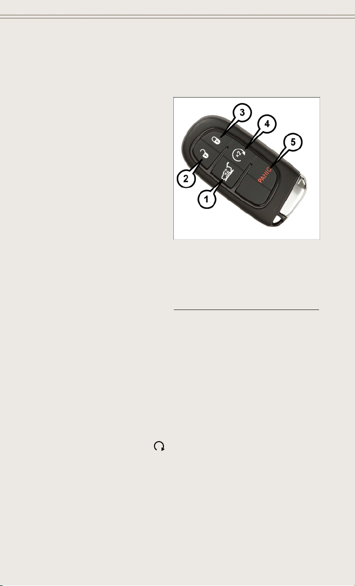
KEY FOB
Locking And Unlocking The Doors/Liftgate
• Push the LOCK button once to lock all
the doors and the liftgate.
• Push the UNLOCK button once to unlock the driver’s door only and twice
within five seconds to unlock all the
doors and liftgate.
All doors can be programmed to unlock
on the first push of the UNLOCK button.
Refer to Programmable Features in the
Electronics section of this guide.
Power Liftgate
• Push the LIFTGATE button on the Key
Fob twice within five seconds to power
open/close the Power Liftgate. If the
button is pushed while the liftgate is
being power closed, the liftgate will
reverse to the full open position.
• Also, the power liftgate may be closed
by pushing the LIFTGATE switch located on the left rear trim panel, near the
liftgate opening. Pushing once will close the liftgate only. This button cannot be
used to open the liftgate.
1 — Liftgate
2 — Unlock
3 — Lock
4 — Remote Start
5 — Panic
Panic Alarm
• Push the PANIC button once to turn the panic alarm on.
• Wait approximately three seconds and press the button a second time to turn the
panic alarm off.
Key Fob
REMOTE START
x
• Push the REMOTE START button
Pushing the REMOTE START button a third time shuts the engine off.
• To drive the vehicle, with a valid Keyless Enter-N-Go™ Key Fob within 5 ft (1.5m)
of the driver's side of the vehicle, grab the front driver door handle to unlock the
driver's door automatically, then push the START/STOP button.
With remote start, the engine will only run for 15 minutes (timeout) unless the
ignition is placed in the ON/RUN position.
10
2
on the Key Fob twice within five seconds.
GETTING STARTED
The vehicle must be started with the ENGINE START/STOP button after two consecutive
timeouts.
NOTE:
For 3.0L Diesel Engine, please refer to “Things To Know Before Starting Your Vehicle”
located in your Diesel Supplement.
WARNING!
• Do not start or run an engine in a closed garage or confined area. Exhaust gas
contains Carbon Monoxide (CO) which is odorless and colorless. Carbon
Monoxide is poisonous and can cause you or others to be severely injured or
killed when inhaled.
• Keep Key Fob transmitters away from children. Operation of the Remote Start
System, windows, door locks or other controls could cause you and others to be
severely injured or killed.
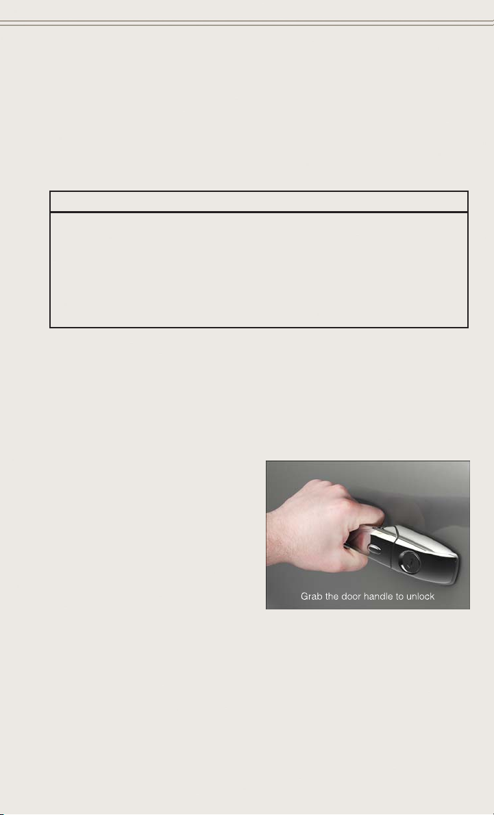
KEYLESS ENTER-N-GO™
The Keyless Enter-N-Go™ system is an enhancement to the vehicle’s Remote
Keyless Entry (RKE) feature. This feature allows you to lock and unlock the vehicle's
door(s) and liftgate without having to push the Key Fob lock or unlock buttons, as well
as starting and stopping the vehicle with the push of a button.
To Unlock From The Driver Or Passenger Side:
With a Passive Entry RKE transmitter
within 5 ft (1.5 m) of the driver's door
handle, grab the driver's front door
handle to unlock the driver's door automatically. The interior door panel lock
knob will raise when the door is unlocked.
11
GETTING STARTED
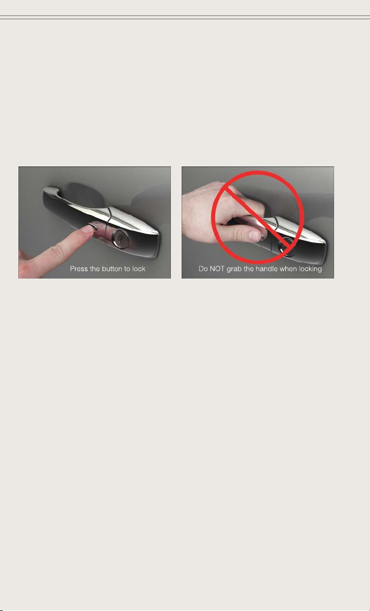
To Lock The Vehicle:
Both front door handles have LOCK buttons located on the outside of the handle.
With one of the vehicles Remote Keyless Entry (RKE) Key Fobs located outside the
vehicle and within 5 ft (1.5 m) of the driver's or passenger front door handle, push the
door handle LOCK button to lock all four doors and liftgate.
DO NOT grab the door handle, when pushing the door handle lock button. This could
unlock the door(s).
NOTE:
• If “Unlock All Doors 1st Push” is programmed all doors will unlock when you grab
hold of the front driver's door handle. To select between “Unlock Driver Door 1st
Push” and “Unlock All Doors 1st Push”, refer to the Uconnect
your vehicles Owner's Manual on the DVD or Programmable Features in this guide
for further information.
• If “Unlock All Doors 1st Push” is programmed all doors and liftgate will unlock
when you push the liftgate button. If “Unlock Driver Door 1st Push” is programmed only the liftgate will unlock when you push the liftgate button. To select
between “Unlock Driver Door 1st Push” and “Unlock All Doors 1st Push”, refer to
the Uconnect
Programmable Features in this guide for further information.
• If a Key Fob is detected in the vehicle when locking the vehicle using the power
door lock switch, the doors and liftgate will unlock and the horn will chirp three
times. On the third attempt, your Key Fob can be locked inside the vehicle.
• After pushing the RKE LOCK button, you must wait two seconds before you can
lock or unlock the vehicle using the door handle. This is done to allow you to check
if the vehicle is locked by pulling on the door handle without the vehicle reacting
and unlocking.
• If a Keyless Enter-N-Go™ door handle has not been used for 72 hours, the Keyless
Enter-N-Go™ feature for that handle may time out. Pulling the deactivated front
door handle will reactivate the door handle's Keyless Enter-N-Go™ feature.
®
System settings in your vehicle's Owner's Manual on the DVD or
®
System settings in
12
GETTING STARTED
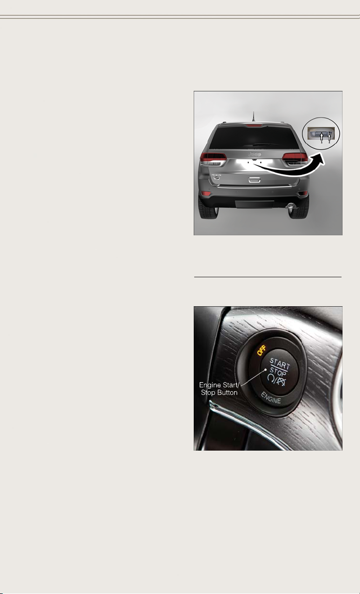
Lock Or Unlock The Liftgate
• To Lock The Liftgate — With a Remote
Keyless Entry (RKE) transmitter within
3 ft (1.0 m) of the liftgate, push the
passive entry lock button located to the
right of electronic liftgate handle.
• To Unlock/Enter The Liftgate — The
liftgate passive entry unlock feature
is built into the electronic liftgate
handle. With a Remote Keyless Entry
(RKE) transmitter within 3 ft (1.0 m)
of the liftgate, push the electronic release switch to open the liftgate.
NOTE:
Refer to your Owner's Manual on the DVD
for further information.
Engine Starting/Stopping
Starting
Perform the following starting procedure
with a Remote Keyless Entry (RKE) transmitter inside the vehicle:
1. Place the shift lever in PARK or NEU-
TRAL.
2. While pushing the brake pedal, push
the ENGINE START/STOP button
once. If the engine fails to start, the
starter will disengage automatically
after 10 seconds.
3. To stop the cranking of the engine
prior to the engine starting, push the
button again.
Electronic Release Switch Location
1 — Electronic Release Switch
2 — Lock Button Location
13
GETTING STARTED
Stopping
1. Bring the vehicle to a complete stop.
2. Shift the transmission to PARK (P).
3. Push the ENGINE START/STOP button once. The ignition switch will return to the
OFF position.
NOTE:
If the transmission is not in PARK and the vehicle is in motion, the ENGINE
START/STOP button must be held for two seconds with the vehicle speed above
5 mph (8 km/h) before the engine will shut off.
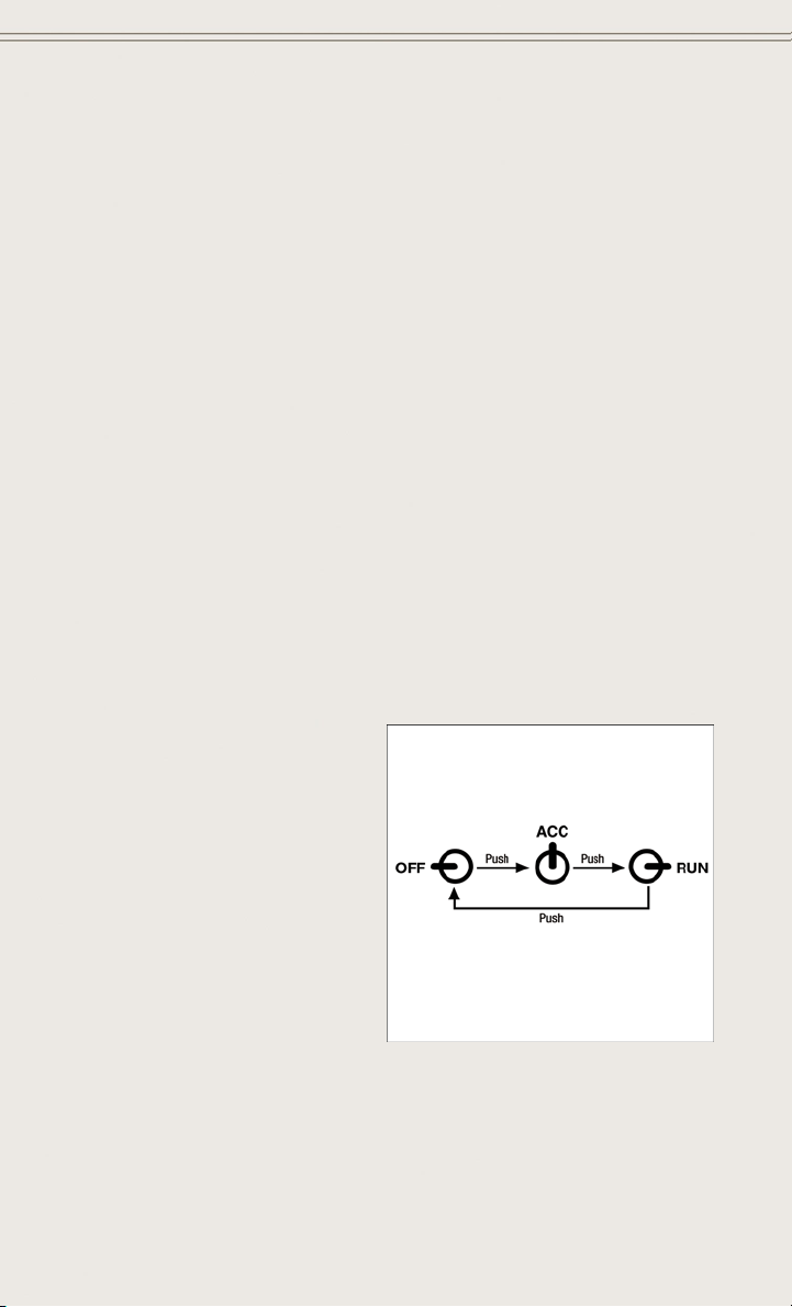
Accessory Positions With Engine Off
NOTE:
The following functions are with the driver’s foot OFF the Brake Pedal (transmission
in PARK or NEUTRAL).
Beginning With The Ignition Switch In The OFF Position:
• Push the ENGINE START/STOP button once to cycle the ignition to the ACC
position.
• Push the ENGINE START/STOP button a second time to cycle the ignition to the
ON/RUN position.
• Push the ENGINE START/STOP button a third time to return the ignition to the
OFF position.
NOTE:
If the ignition is left in the ACC or ON/
RUN (engine not running) position and
the transmission is in PARK, the system
will automatically time out after 30 minutes of inactivity and the ignition is returned to the OFF position.
14
Accessory Positions

GETTING STARTED
VEHICLE SECURITY ALARM
This Vehicle Security Alarm monitors the doors, liftgate, and ignition switch for
unauthorized operation.
When the alarm is activated, the interior switches for door locks are disabled. The
Vehicle Security Alarm provides both audio and visual signals repeatedly for three
minutes. If the disturbance is still present (driver's door, passenger door, other doors,
ignition) after three minutes, the parking lights and tail lights will flash for an additional
15 minutes.
To Ar m
Cycle the Keyless Enter-N-Go™ START/STOP button until the button display indicates that the vehicle ignition is “OFF”. Push the power door lock switch while the
door is open, push the Key Fob LOCK button, or with one of the Key Fobs located
outside the vehicle and within 5 ft (1.5 m) of the driver's and passenger front door
handles, push the Keyless Enter-N-Go™ LOCK button located on the door handle.
NOTE:
After pushing the Keyless Enter-N-Go™ LOCK button, you must wait two seconds
before you can lock or unlock the vehicle via the door handle.
To Disarm
Push the Key Fob UNLOCK button or with one of the Key Fobs located outside the
vehicle and within 5 ft (1.5 m) of the driver's and passenger front door handles, grab
the Keyless Enter-N-Go™ door handle and enter the vehicle, then push the Keyless
Enter-N-Go™ START/STOP button (requires at least one valid Key Fob in the vehicle).
SEAT BELT
Be sure everyone in your vehicle is in a seat and using a seat belt properly.
• Position the lap belt across your thighs, below your abdomen. To remove slack in
the lap portion, pull up a bit on the shoulder belt. To loosen the lap belt if it is too
tight, tilt the latch plate and pull on the lap belt. A snug belt reduces the risk of
sliding under the belt in a collision.
• Position the shoulder belt on your chest so that it is comfortable and not resting
on your neck. The retractor will withdraw any slack in the belt.
A shoulder belt placed behind you will not protect you from injury during a collision.
You are more likely to hit your head in a collision if you do not wear your shoulder belt.
The lap and shoulder belt are meant to be used together.
A belt that is too loose will not protect you properly. In a sudden stop you could move
too far forward, increasing the possibility of injury. Wear your seat belt snugly.
15

GETTING STARTED
A frayed or torn belt could rip apart in a collision and leave you with no protection.
Inspect the belt system periodically, checking for cuts, frays, or loose parts. Damaged
parts must be replaced immediately. Do not disassemble or modify the system. Seat
belt assemblies must be replaced after a collision if they have been damaged (bent
retractor, torn webbing, etc.).
T
he seat belts for both front seating positions are equipped with pretensioning devices
that are designed to remove slack from the seat belt in the event of a collision.
A deployed pretensioner or a deployed air bag must be replaced immediately.
WARNING!
In a collision, you and your passengers can suffer much greater injuries if you are
not properly buckled up. You can strike the interior of your vehicle or other
passengers, or you can be thrown out of the vehicle. Always be sure you and others
in your vehicle are buckled up properly.
SUPPLEMENTAL RESTRAINT SYSTEM (SRS) — AIR BAGS
This vehicle has Advanced Front Air Bags for both the driver and front passenger as
a supplement to the seat belt restraint systems. The driver's Advanced Front Air Bag
is mounted in the center of the steering wheel. The passenger's Advanced Front Air
Bag is mounted in the instrument panel, above the glove compartment. The words
SRS AIR BAG are embossed on the air bag covers.
Advanced Front Air Bags are designed to provide additional protection by supplementing the seat belts in certain frontal collisions depending on several factors,
including the severity and type of collision. Advanced Front Air Bags are not expected
to reduce the risk of injury in rear, side, or rollover collisions.
This vehicle is equipped with Supplemental Side Air Bag Inflatable Curtains to
protect the driver, front and rear passengers sitting next to a window.
This vehicle is equipped with Supplemental Seat-Mounted Side Air Bags to provide
enhanced protection to help protect an occupant during a side impact.
This vehicle is equipped with Supplemental Driver’s Side Knee Air Bag mounted in
the instrument panel below the steering column and a Knee Bolster mounted below
the glove compartment. The Supplemental Driver’s Side Knee Air Bag provides
enhanced protection and works together with the Driver Advanced Front Air Bag
during a frontal impact.
If the Air Bag Warning Light
driving, have the vehicle serviced by an authorized service center immediately.
Refer to the Owner's Manual on the DVD for further details regarding the Supplemental Restraint System (SRS).
is not on during starting, stays on, or turns on while
16

GETTING STARTED
WARNING!
• Relying on the air bags alone could lead to more severe injuries in a collision.
The air bags work with your seat belt to restrain you properly. In some
collisions, the air bags won't deploy at all. Always wear your seat belts even
though you have air bags.
• Being too close to the steering wheel or instrument panel during Advanced
Front Air Bag deployment could cause serious injury, including death. Air bags
need room to inflate. Sit back, comfortably extending your arms to reach the
steering wheel or instrument panel.
• Supplemental Side Air Bag Inflatable Curtains and Supplemental SeatMounted Side Air Bags need room to inflate. Do not lean against the door or
window. Sit upright in the center of the seat.
• Being too close to the Supplemental Side Air Bag Inflatable Curtain and/or
Seat-Mounted Side Air Bag during deployment could cause you to be severely
injured or killed.
• Do not drive your vehicle after the air bags have deployed. If you are involved
in another collision, the air bags will not be in place to protect you.
• After any collision, the vehicle should be taken to an authorized dealer
immediately.
CHILD RESTRAINTS
Children 12 years or younger should ride properly buckled up in a rear seat, if
available. According to crash statistics, children are safer when properly restrained in
the rear seats rather than in the front.
Every state in the United States and all Canadian provinces require that small
children ride in proper restraint systems. This is the law, and you can be prosecuted
for ignoring it.
NOTE:
For additional information, refer to www.seatcheck.org or call 1–866–SEATCHECK
•
(1–866–732–8243).
• Canadian residents, should refer to Transport Canada’s website for additional
information:
http://www.tc.gc.ca/eng/roadsafety/safedrivers-childsafety-index-53.htm
LATCH — Lower Anchors And Tethers For CHildren
• Your vehicle is equipped with the child restraint anchorage system called LATCH,
which stands for Lower Anchors and Tethers for CHildren.
• The rear outboard seating positions have lower anchors and top tether anchors.
The rear center seating position has a top tether anchor only.
17
GETTING STARTED
• You may use the LATCH anchorage
system until the combined weight of
the child and the child restraint is
65 lbs (29.5 kg). Use the seat belt and
tether anchor instead of the LATCH
system once the combined weight is
more than 65 lbs (29.5 kg).
The lower anchorages are round
•
bars that are found at the rear of the
seat cushion where it meets the seatback, below the anchorage symbols on
the seatback. They are just visible
when you lean into the rear seat to install the child restraint. You will easily feel
them if you run your finger along the gap between the seatback and seat cushion.
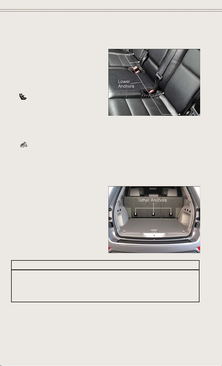
•
In addition, there are tether strap anchorages behind each rear seating
position located on the back of the seat. To access the top tether strap anchorages
behind the rear seat, pull the carpeted floor panel away from the seat back, this
will expose the top tether strap anchorages. DO NOT USE the cargo tie down loops
located on the load floor as tether anchorages.
WARNING!
Do not install a child restraint in the center position using the LATCH system. This
position is not approved for installing child seats using the LATCH attachments.
You must use the seat belt and tether anchor to install a child seat in the center
seating position.
18

GETTING STARTED
Installing The Child Restraint Using The LATCH Lower Anchors
NOTE:
Never “share” a LATCH anchorage with two or more child restraints.
1. Loosen the adjusters on the lower straps and on the tether strap of the child seat
so that you can more easily attach the hooks or connectors to the vehicle
anchorages.
2. Attach the lower hooks or connectors of the child restraint to the lower anchorages
in the selected seating position.
3. If the child restraint has a tether strap, connect it to the top tether anchorage. See
below for directions to attach a tether anchor.
4. Tighten all of the straps as you push the child restraint rearward and downward
into the seat. Remove slack in the straps according to the child restraint
manufacturer’s instructions.
5. Test that the child restraint is installed tightly by pulling back and forth on the
child seat at the belt path. It should not move more than 1 inch (25.4 mm) in any
direction.
Installing The Child Restraint Using The Vehicle Seat Belts
The seat belts in the passenger seating positions are equipped with a Switchable
Automatic Locking Retractor (ALR) that is designed to keep the lap portion of the
seat belt tight around the child restraint. Any seat belt system will loosen with time,
so check the belt occasionally, and pull it tight if necessary.
Always use the tether anchor when using the seat belt to install a forward facing child
restraint, up to the recommended weight limit of the child restraint.
To Install A Child Seat Using An ALR:
1. Pull enough of the seat belt webbing from the retractor to pass it through the belt
path of the child restraint. Do not twist the belt webbing in the belt path.
2. Slide the latch plate into the buckle until you hear a “click.”
3. Pull on the webbing to make the lap portion tight against the child seat.
4. To lock the seat belt, pull down on the shoulder part of the belt until you have
pulled all the seat belt webbing out of the retractor. Then, allow the webbing to
retract back into the retractor. As the webbing retracts, you will hear a clicking
sound. This means the seat belt is now in the Automatic Locking mode.
19

GETTING STARTED
5. Try to pull the webbing out of the retractor. If it is locked, you should not be able
to pull out any webbing. If the retractor is not locked, repeat the last step.
6. Finally, pull up on any extra webbing to tighten the lap portion around the child
restraint while you push the child restraint rearward and downward into the
vehicle seat.
7. If the child restraint has a top tether strap and the seating position has a top tether
anchorage, connect the tether strap to the anchorage and tighten the tether strap.
See below for directions to attach a tether anchor.
8. Test that the child restraint is installed tightly by pulling back and forth on the
child seat at the belt path. It should not move more than 1 inch (25.4 mm) in any
direction.
Installing The Top Tether Strap (With Either Lower Anchors Or Vehicle Seat Belt):
When installing a forward-facing child restraint, always secure the top tether strap,
up to the tether anchor weight limit, whether the child restraint is installed with the
lower anchors or the vehicle seat belt.
1. To access the top tether strap anchorages behind the rear seat, pull the carpeted
floor panel away from the seat back, this will expose the top tether strap
anchorages.
2. Route the tether strap to provide the most direct path for the strap between the
anchor and the child seat.
3. If your vehicle is equipped with adjustable rear head restraints, raise the head
restraint, and where possible, route the tether strap under the head restraint and
between the two posts. If not possible, lower the head restraint and pass the
tether strap around the outboard side of the head restraint.
4. For the center seating position, route the tether strap over the seatback and
headrest.
5. Attach the tether strap hook of the child restraint to the top tether anchorage and
remove slack in the tether strap according to the child restraint manufacturer’s
instructions.
WARNING!
DO NOT USE the cargo tie down loops located on the load floor as tether
anchorages.
20
GETTING STARTED
WARNING!
• In a collision, an unrestrained child, even a tiny baby, can become a projectile
inside the vehicle. The force required to hold even an infant on your lap could
become so great that you could not hold the child, no matter how strong you
are. The child and others could be severely injured or killed. Any child riding in
your vehicle should be in a proper restraint for the child's size.
• Rearward-facing child seats must never be used in the front seat of a vehicle
with a front passenger air bag. An air bag deployment could cause severe injury
or death to infants in this position.
• Only use a rearward-facing child restraint in a vehicle with a rear seat.
• Improper installation of a child restraint to the LATCH anchorages can lead to
failure of an infant or child restraint. The child could be severely injured or
killed. Follow the manufacturer’s directions exactly when installing an infant or
child restraint.
• An incorrectly anchored tether strap could lead to increased head motion and
possible injury to the child. Use only the anchor positions directly behind the
child seat to secure a child restraint top tether strap.
• If your vehicle is equipped with a split rear seat, make sure the tether strap
does not slip into the opening between the seatbacks as you remove slack in
the strap.
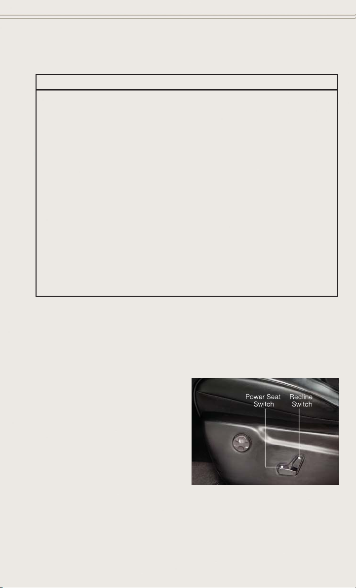
FRONT SEATS
Power Seats
The power seat switch controls forward/back, up/down and tilt adjustment.
The recline switch, located on the outboard side of the seat, controls seatback
adjustment.
21
GETTING STARTED
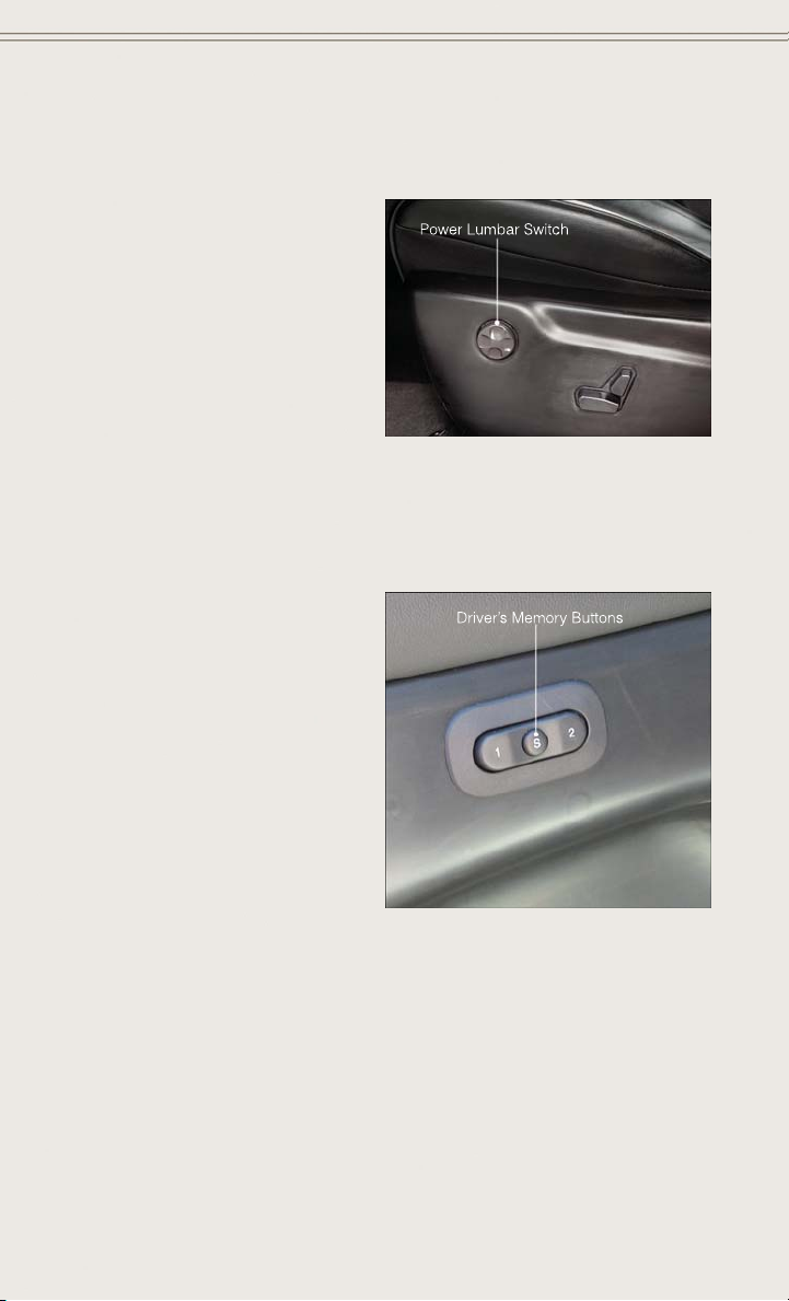
Power Lumbar
• Push the switch forward to increase
the lumbar support. Push the switch
rearward to decrease the lumbar support.
• Pushing upward or downward on the
switch will raise and lower the position
of the support.
Memory Seat
The memory seat feature allows you to save two different driver seating positions
(excluding lumbar position), driver's outside mirror, tilt/telescoping steering column
position, and radio station preset settings. The memory seat buttons are located on
the driver's door panel.
• Adjust all memory profile settings,
press the SET button then press 1 or 2
within five seconds.
• To program a Key Fob to the memory
position, place the ignition switch in
the LOCK position, press and release
the LOCK button on the Key Fob to be
programmed within five seconds of
pressing button 1 or 2.
Place the ignition switch in the ON/RUN
•
position, select “Remote to Memory” in
the Uconnect
“Yes”.
• Press 1 or 2 to recall the saved positions, or press UNLOCK on the programmed Key Fob.
Refer to the Owner's Manual on the DVD for further details.
®
system screen and enter
22
GETTING STARTED
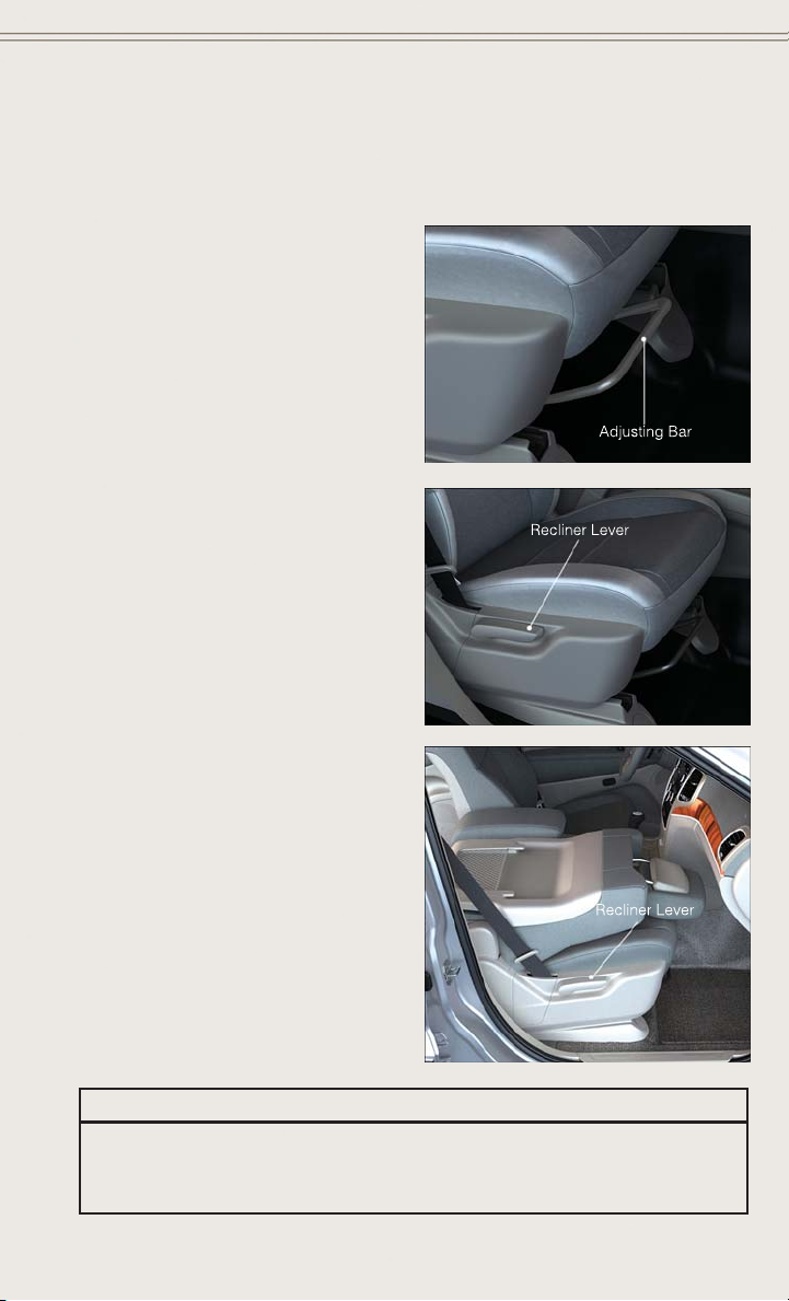
Manual Seat Adjustment
Forward/Rearward
• Lift up on the adjusting bar located at
the front of the seat near the floor and
release it when the seat is at the desired position. Then, using body pressure, move forward and backward on
the seat to be sure that the seat adjusters have latched.
Recliner
•
Lift the rear lever located on the outboard side of the seat, lean back and
release when seat is in desired position.
Fold-Flat Front Passenger Seat
The front passenger seat can be folded
flat to allow for extended cargo space.
• Pull up on the recliner lever to fold
down the seatback.
CAUTION!
Do not place any article under a power seat or impede its ability to move as it may
cause damage to the seat controls. Seat travel may become limited if movement
is stopped by an obstruction in the seat's path.
23
GETTING STARTED
WARNING!
• Adjusting a seat while the vehicle is moving is dangerous. The sudden
movement of the seat could cause you to lose control. The seat belt might not
be properly adjusted, and you could be severely injured or killed. Only adjust a
seat while the vehicle is parked.
• Do not ride with the seatback reclined so that the seat belt is no longer resting
against your chest. In a collision, you could slide under the seat belt and be
severely injured or killed. Use the recliner only when the vehicle is parked.
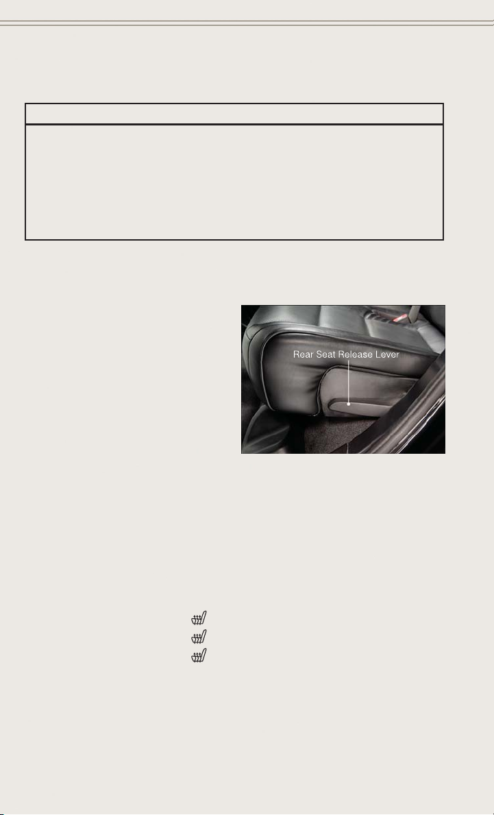
REAR SEATS
60/40 Split Rear Seat
To Lower Rear Seatback
• With the front seats fully upright and
positioned forward, pull upward on the
release lever and fold the rear seatback
down.
To Raise Rear Seatback
• Raise the rear seatback and lock it into
place.
To Recline Rear Seatback
• To recline the seatback, lean forward
before lifting the handle, then lean back to the desired position and release the
handle. Lift the handle to return the seatback to an upright position.
HEATED/VENTILATED SEATS
Front Heated Seats
The front heated seats control buttons are located within the climate or controls
screen of the touchscreen.
• Press the heated seat button
• Press the heated seat button
• Press the heated seat button
If the High-level setting is selected, the system will automatically switch to Low-level
after approximately 60 minutes. The Low-level setting will turn Off automatically
after approximately 45 minutes.
24
once to turn the High setting On.
a second time to turn the Low setting On.
a third time to turn the heating elements Off.
GETTING STARTED
NOTE:
Vehicle Equipped With Remote Start
On models that are equipped with remote start, this feature can be programmed to come
on during a remote start through the Uconnect
“Understanding Your Instrument Panel” in the Owner's Manual on the DVD.
Front Ventilated Seats
Located in the seat cushion and seatback are small fans that draw the air from the
passenger compartment and pull air through fine perforations in the seat cover to
help keep the driver and front passenger cooler in higher ambient temperatures.
There are two ventilated seat control buttons located in the touchscreen that allow
the driver and passenger to operate the seats independently.
The ventilated seat buttons are used to control the speed of the fans located in the seat.
To operate the system, press the “Controls” button on touchscreen located on the
bottom of the Uconnect
• Press the ventilated seat button
• Press the ventilated seat button
• Press the ventilated seat button
NOTE:
Vehicle Equipped With Remote Start
On models that are equipped with remote start, this feature can be programmed to come
on during a remote start through the Uconnect
“Understanding Your Instrument Panel” in the Owner's Manual on the DVD.
®
display.
®
system. Refer to “Uconnect®Settings” in
once to choose HIGH.
a second time to choose LOW.
a third time to turn the ventilated seat OFF.
®
system. Refer to “Uconnect®Settings” in
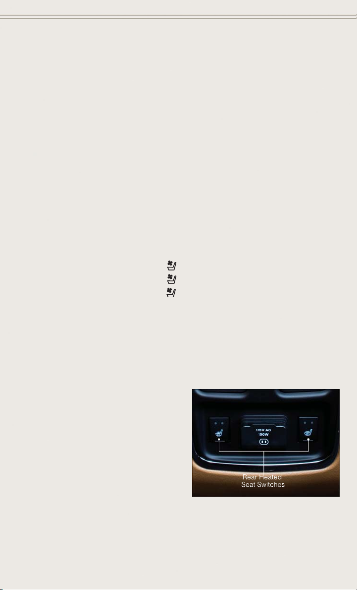
Rear Heated Seats
Second row heated seat switches are located on the rear of the center console:
• Press the switch once to select Highlevel heating.
• Press the switch a second time to
select Low-level heating.
• Press the switch a third time to shut
the heating elements Off.
• If the High-level setting is selected,
the system will automatically switch to
Low-level after approximately 60 minutes. The Low-level setting will turn Off
automatically after approximately 45 minutes.
25

GETTING STARTED
WARNING!
• Persons who are unable to feel pain to the skin because of advanced age,
chronic illness, diabetes, spinal cord injury, medication, alcohol use, exhaustion or other physical conditions must exercise care when using the seat heater.
It may cause burns even at low temperatures, especially if used for long periods
of time.
• Do not place anything on the seat that insulates against heat, such as a blanket
or cushion. This may cause the seat heater to overheat. Sitting in a seat that
has been overheated could cause serious burns due to the increased surface
temperature of the seat.
HEATED STEERING WHEEL
The steering wheel contains a heating element that heats the steering wheel to one
temperature setting.
The heated steering wheel control button is located within the climate or controls
screen of the touchscreen.
• Press the heated steering wheel button
• Press the heated steering wheel button
element Off.
Once the heated steering wheel has been turned on, it will operate for approximately
58 to 70 minutes before automatically shutting off. The heated steering wheel can
shut off early or may not turn on when the steering wheel is already warm.
NOTE:
Vehicle Equipped With Remote Start
On models that are equipped with remote start, this feature can be programmed to come
on during a remote start through the Uconnect
in “Understanding Your Instrument Panel” in the Owner's Manual on the DVD.
once to turn the heating element On.
a second time to turn the heating
®
system. Refer to “Uconnect®Settings”
WARNING!
• Persons who are unable to feel pain to the skin because of advanced age,
chronic illness, diabetes, spinal cord injury, medication, alcohol use, exhaustion, or other physical conditions must exercise care when using the steering
wheel heater. It may cause burns even at low temperatures, especially if used
for long periods.
• Do not place anything on the steering wheel that insulates against heat, such
as a blanket or steering wheel covers of any type and material. This may cause
the steering wheel heater to overheat.
26
GETTING STARTED
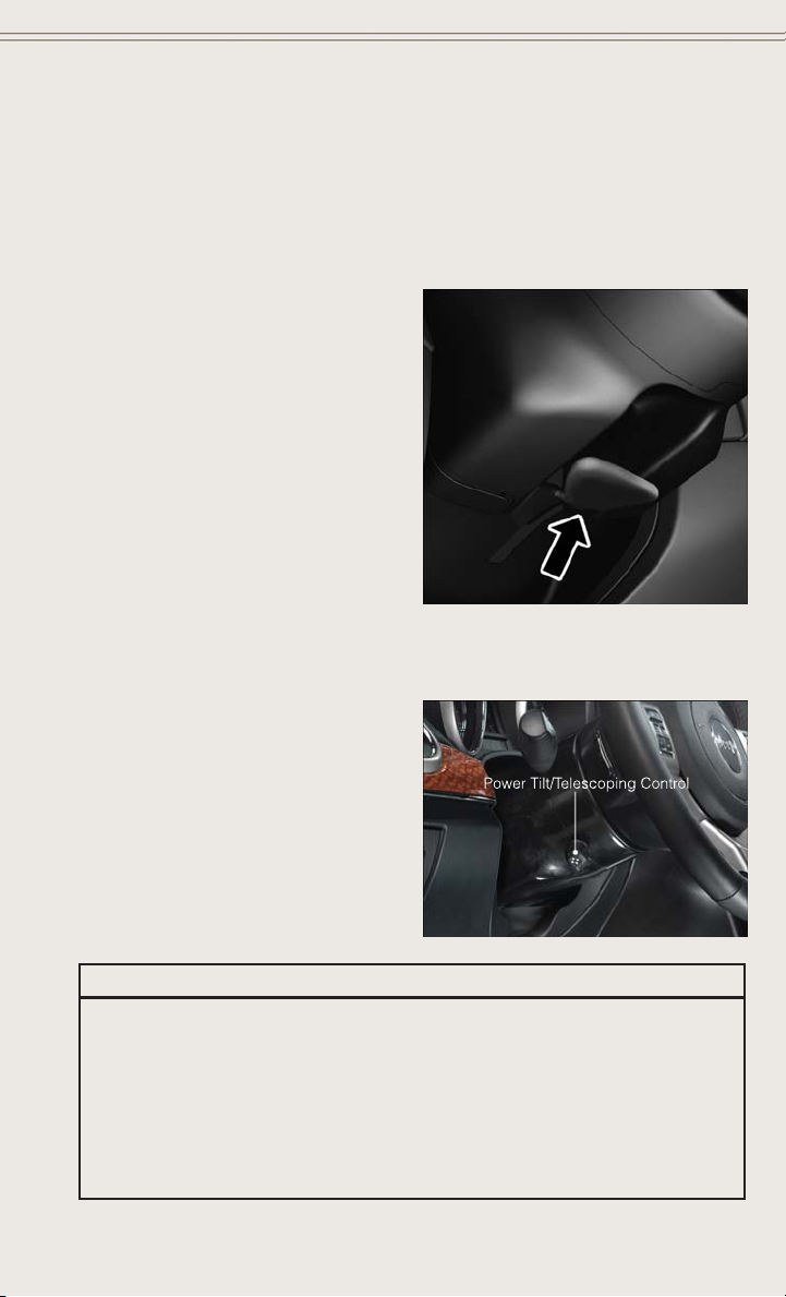
TILT/TELESCOPING STEERING COLUMN
Manual Tilt/Telescoping Steering Column
The tilt/telescoping control handle is located below the steering wheel at the end of
the steering column.
• Push the handle down to unlock the
steering column.
• To tilt the steering column, move the
steering wheel upward or downward as
desired.
• To lengthen or shorten the steering
column, pull the steering wheel outward or push it inward as desired.
• Pull up on the handle to lock the
column firmly in place.
Power Tilt/Telescoping Steering Column
The power tilt/telescoping steering control is located below the turn signal/wiper/
washer/high beam lever on the steering column.
• To tilt the steering column, move the
power tilt/telescoping control up or
down as desired.
• To lengthen or shorten the steering
column, pull the control toward you
or push the control away from you as
desired.
WARNING!
• Do not adjust the steering wheel while driving. The tilt/telescoping adjustment
must be locked while driving. Adjusting the steering wheel while driving or
driving without the tilt/telescoping adjustment locked could cause the driver to
lose control of the vehicle. Failure to follow this warning may result in you and
others being severely injured or killed.
• Moving the steering column while the vehicle is moving is dangerous. Without
a stable steering column, you could lose control of the vehicle and have a
collision. Adjust the column only while the vehicle is stopped.
27

OPERATING YOUR VEHICLE
ENGINE BREAK-IN RECOMMENDATIONS
A long break-in period is not required for the engine and drivetrain (transmission and
axle) in your vehicle.
Drive moderately during the first 300 miles (500 km). After the initial 60 miles
(100 km), speeds up to 50 or 55 mph (80 or 90 km/h) are desirable.
While cruising, brief full-throttle acceleration within the limits of local traffic laws
contributes to a good break-in. Wide-open throttle acceleration in low gear can be
detrimental and should be avoided.
The engine oil installed in the engine at the factory is a high-quality energy
conserving type lubricant. Oil changes should be consistent with anticipated climate
conditions under which vehicle operations will occur. For the recommended viscosity
and quality grades, refer to “Maintaining Your Vehicle.”
NOTE:
A new engine may consume some oil during its first few thousand miles (kilometers)
of operation. This should be considered a normal part of the break-in and not
interpreted as an indication of an engine problem or malfunction.
CAUTION!
Never use Non-Detergent Oil or Straight Mineral Oil in the engine or damage may
result.
SRT Engine Break-In Recommendations
SRT Engine Break-In Recommendations: The following tips will be helpful in
obtaining optimum performance and maximum durability for your new SRT Vehicle.
Despite modern technology and World Class manufacturing methods, the moving
parts of the vehicle must still wear in with each other. This wearing in occurs mainly
during the first 500 miles (805 km) and continues through the first oil change
interval.
It is recommended for the operator to observe the following driving behaviors during
the new vehicle break-in period:
0 to 100 miles (0 to 161 km):
• Do not allow the engine to operate at idle for an extended period of time.
• Depress the accelerator pedal slowly and not more than halfway to avoid rapid
acceleration.
• Avoid aggressive braking.
• Drive with the engine speed less than 3,500 RPM.
• Maintain vehicle speed below 55 mph (88 km/h) and observe local speed limits.
28

OPERATING YOUR VEHICLE
100 to 300 miles (161 to 483 km):
• Depress the accelerator pedal slowly and not more than halfway to avoid rapid
acceleration in lower gears (1st to 3rd gears).
• Avoid aggressive braking.
• Drive with the engine speed less than 5,000 RPM.
• Maintain vehicle speed below 70 mph (112 km/h) and observe local speed limits.
300 to 500 miles (483 to 805 km):
• Exercise the full engine rpm range, shifting manually (paddles or gear shift) at
higher rpms when possible.
• Do not perform sustained operation with the accelerator pedal at wide open
throttle.
• Maintain vehicle speed below 85 mph (136 km/h) and observe local speed limits.
For the first 1500 mi (2414 km):
• Do not participate in track events, sport driving schools, or similar activities during
the first 1500 mi (2414 km).
NOTE:
Check engine oil with every refueling and add if necessary. Oil and fuel consumption
may be higher through the first oil change interval.
HEADLIGHT SWITCH
Automatic Headlights/Parking Lights/Headlights
• Rotate the headlight switch, located
on the instrument panel to the left of
the steering wheel, to the first detent
for parking lights
second detent for headlights
• With the parking lights or low beam
headlights on, push the headlight
switch once for fog lights.
• Rotate the headlight switch to “A” for
AUTO headlights.
When set to “A” (AUTO), the system
automatically turns the headlights on or
off based on ambient light levels.
and to the
.
29

OPERATING YOUR VEHICLE
Automatic High Beams
The Automatic High Beams system provides increased forward lighting at night by
automating high beam control through the use of a digital camera mounted on the
inside rearview mirror. This camera detects vehicle specific light and automatically
switches from high beams to low beams until the approaching vehicle is out of view.
This feature is programmable through the Uconnect
Settings ” in “Understanding Your Instrument Panel” in the Owner's Manual on the
DVD for further details.
Instrument Panel Dimmer
• Rotate the dimmer control to the extreme bottom position to fully dim the
instrument panel lights and prevent the interior lights from illuminating when a
door is opened.
• Rotate the dimmer control up to increase the brightness of the instrument panel
when the parking lights or headlights are on.
• Rotate the dimmer control up to the next detent position to fully brighten the
odometer and radio when the parking lights or headlights are on.
• Rotate the dimmer control up to the last detent position to turn on the interior
lighting.
• If your vehicle is equipped with a touchscreen, the dimming is programmable
through the Uconnect
Your Instrument Panel” in the Owner's Manual on the DVD for further details.
®
system. Refer to “Uconnect®Settings ” in “Understanding
®
system. Refer to “Uconnect
®
TURN SIGNAL/WIPER/WASHER/HIGH BEAM LEVER
Turn Signal/Lane Change Assist
• Tap the lever up or down once and the turn signal (right or left) will flash three
times and automatically turn off.
30

OPERATING YOUR VEHICLE
High Beam Operation
• Push the lever forward to activate the high beams. Pull the lever toward you for
flash to pass.
NOTE:
For safe driving, turn off high beams when oncoming traffic is present to prevent
headlight glare and as a courtesy to other motorists.
Front Wipers
Intermittent, Low And High Operation
• Rotate the end of the lever to the first detent position for one of four intermittent
settings, the second detent for low wiper operation and the third detent for high
wiper operation.
Washer Operation
• Push inward on the end of the lever and hold for as long as spray is desired.
Mist
• Rotate the end of the lever downward when a single wipe is desired.
NOTE:
The mist feature does not activate the washer pump; therefore, no washer fluid will
be sprayed on the windshield. The wash function must be activated in order to spray
the windshield with washer fluid.
Rain Sensing Wipers
This feature senses moisture on the vehicles windshield and automatically activates
the wipers for the driver when the switch is in the intermittent position.
• Rotate the end of the lever to one of four settings to activate this feature and
adjust sensitivity.
®
This feature can be activated/deactivated using the Uconnect
to the “Programmable Features” under the “Electronics” section in this guide.
Refer to the Owner's Manual on the DVD for further details.
Rear Wiper
Rear Wiper Operation
• Rotate the center portion of the lever forward to the first detent for intermittent
operation and to the second detent for rear wiper operation.
Rear Washer Operation
• Rotate the center portion of the lever past the second detent to activate the rear
washer.
system screen. Refer
31
OPERATING YOUR VEHICLE
AUTOMATIC DIMMING MIRRORS
The rearview and driver side exterior mirror automatically adjusts for headlight glare
from vehicles behind you.
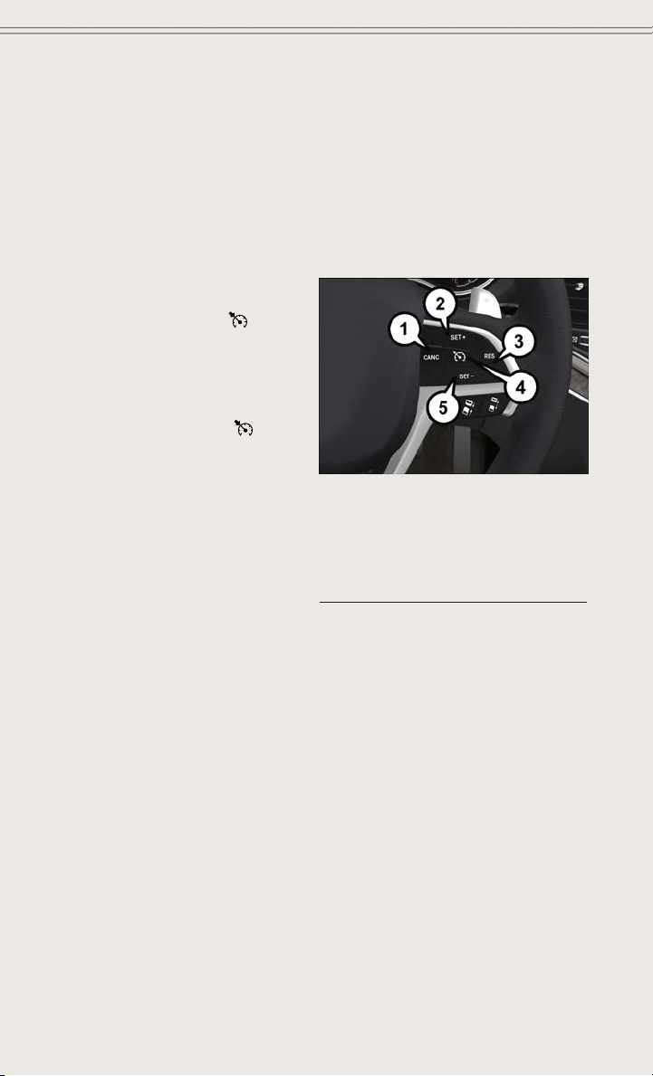
SPEED CONTROL
The Speed Control switches are located on the right side of the steering wheel.
Cruise ON/OFF
• Push the ON/OFF button
vate the Speed Control.
CRUISE CONTROL READY will appear
on the instrument cluster to indicate the
Speed Control is on.
• Push the ON/OFF button
ond time to turn the system off.
CRUISE CONTROL OFF will appear on
the instrument cluster to indicate the
Speed Control is off.
SET
• With the Speed Control on, push and
release the SET+ or SET- button to set
a desired speed.
Once a speed has been set a message
CRUISE CONTROL SET TO MPH/KM will appear indicating what speed was set. An
indicator CRUISE will also appear and stay on in the instrument cluster when the
speed is set.
Accel/Decel
To Increase Speed
• When the Electronic Speed Control is set, you can increase speed by pushing the
SET + button.
The speed increment shown is dependant on the speed of U.S. (mph) or Metric
(km/h) units:
U.S. Speed (mph)
• Pressing the SET + button once will result in a 1 mph increase in set speed. Each
subsequent tap of the button results in an increase of 1 mph.
• If the button is continually pressed, the set speed will continue to increase until
the button is released, then the new set speed will be established.
to acti-
a sec-
Speed Control Switches
1 — Push Cancel
2 — Push Set+/Accel
3 — Push Resume
4 — Push On/Off
5 — Push Set-/Decel
32

OPERATING YOUR VEHICLE
Metric Speed (km/h)
• Pressing the SET + button once will result in a 1 km/h increase in set speed. Each
subsequent tap of the button results in an increase of 1 km/h.
• If the button is continually pressed, the set speed will continue to increase until
the button is released, then the new set speed will be established.
To Decrease Speed
• When the Electronic Speed Control is set, you can decrease speed by pushing the
SET - button.
The speed decrement shown is dependant on the speed of U.S. (mph) or Metric
(km/h) units:
U.S. Speed (mph)
• Pressing the SET - button once will result in a 1 mph decrease in set speed. Each
subsequent tap of the button results in a decrease of 1 mph.
• If the button is continually pressed, the set speed will continue to decrease until
the button is released, then the new set speed will be established.
Metric Speed (km/h)
• Pressing the SET - button once will result in a 1 km/h decrease in set speed. Each
subsequent tap of the button results in a decrease of 1 km/h.
• If the button is continually pressed, the set speed will continue to decrease until
the button is released, then the new set speed will be established.
Resume
• To resume a previously selected set speed in memory, push the RES button and
release.
Cancel
• Push the CANCEL button, or apply the brakes to cancel the set speed and
maintain the set speed memory.
• Push the ON/OFF button to turn the system off and erase the set speed memory.
WARNING!
Leaving the Electronic Speed Control system on when not in use is dangerous. You
could accidentally set the system or cause it to go faster than you want. You could
lose control and have an accident. Always leave the system OFF when you are not
using it.
33

OPERATING YOUR VEHICLE
ADAPTIVE CRUISE CONTROL (ACC)
If your vehicle is equipped with adaptive
cruise control the controls operate exactly the same as the normal (fixed
speed) cruise control with one difference.
You can set a specified distance you
would like to maintain between you and
the vehicle in front of you.
If the ACC sensor detects a vehicle
ahead, ACC will apply limited braking or
acceleration automatically to maintain a
preset following distance, while matching the speed of the vehicle ahead.
If the sensor does not detect a vehicle
ahead of you, ACC will maintain a fixed
set speed.
ACC ON/OFF
• Push and release the Adaptive Cruise Control (ACC) ON/OFF button.
ACC READY will appear on the instrument cluster to indicate the ACC is on.
• Push and release the Adaptive Cruise Control (ACC) ON/OFF button a second time
to turn the system off.
Adaptive Cruise Control (ACC) Off will appear on the instrument cluster to indicate
the ACC is off.
1 — Adaptive Cruise Control (ACC)
On/Off
2 — Distance Setting – Decrease
3 — Distance Setting – Increase
Distance Setting (ACC Only)
The specified following distance for ACC can be set by varying the distance setting
between four bars (longest), three bars (long), two bars (medium) and one bar (short).
Using this distance setting and the vehicle speed, ACC calculates and sets the
distance to the vehicle ahead. This distance setting displays in the EVIC.
• To increase the distance setting, press the Distance Setting—Increase button and
release. Each time the button is pressed, the distance setting increases by one bar
(longer).
• To decrease the distance setting, press the Distance Setting—Decrease button
and release. Each time the button is pressed, the distance setting decreases by
one bar (shorter).
34

OPERATING YOUR VEHICLE
ACC Operation At Stop
If the ACC system brings your vehicle to a standstill while following a target vehicle,
if the target vehicle starts moving within two seconds of your vehicle coming to a
standstill, your vehicle will resume motion without the need for any driver action.
If the target vehicle does not start moving within two seconds of your vehicle coming
to a standstill, the ACC with Stop system will cancel and the brakes will ramp-out.
Driver intervention will be required at this moment.
While ACC with Stop is holding your vehicle at a standstill, if the driver seatbelt is
unbuckled or the driver door is opened, the ACC with Stop system will cancel and the
brakes will ramp-out. Driver intervention will be required at this moment.
Changing Modes (ACC Only)
If desired, the Adaptive Cruise Control mode can be turned off and the system can be
operated as a normal (Fixed Speed) Speed Control mode. When in the normal (Fixed
Speed) Speed Control mode the distance setting feature will be disabled and the
system will maintain the speed you set.
• To change between the different cruise control modes, press the ADAPTIVE
CRUISE CONTROL (ACC) ON/OFF button which turns the ACC and the normal
(Fixed Speed) Speed Control OFF.
• Pressing the normal (Fixed Speed) SPEED CONTROL ON/OFF button will result in
turning ON (changing to) the normal (Fixed Speed) Speed Control mode.
Refer to your Owner's Manual on the DVD for further information.
35

OPERATING YOUR VEHICLE
FORWARD COLLISION WARNING (FCW) WITH MITIGATION
The Forward Collision Warning (FCW) system with mitigation provides the driver with
audible warnings, visual warnings within the EVIC, and may apply a brake jerk to
warn the driver when it detects a potential frontal collision. The warnings and limited
braking are intended to provide the driver with enough time to react, avoid or mitigate
the potential collision.
NOTE:
FCW monitors the information from the forward looking sensors as well as the
Electronic Brake Controller (EBC), to calculate the probability of a forward collision.
When the system determines that a forward collision is probable, the driver will be
provided with audible and visual warnings and may provide a brake jerk warning.
If the driver does not take action based upon these progressive warnings, then the
system will provide a limited level of active braking to help slow the vehicle and
mitigate the potential forward collision. If the driver reacts to the warnings by braking
and the system determines that the driver intends to avoid the collision by braking
but has not applied sufficient brake force, the system will compensate and provide
additional brake force as required.
Turning FCW ON Or OFF
NOTE:
The default status of FCW is “On”, this allows the system to warn you of a possible
collision with the vehicle in front of you when you are farther away and it applies
limited braking. This gives you the most reaction time to avoid a possible collision.
The forward collision button is on the switch panel that is located in the center of the
instrument panel.
To turn the FCW system OFF, press the forward collision button once (LED turns on).
•
• To turn the FCW system back ON, press the forward collision button again (LED
turns off).
Changing FCW Status
®
The FCW feature has two settings and can be changed within the Uconnect
Screen:
• Far
• Near
NOTE:
The FCW and active braking settings can only be changed when the vehicle is in
PARK.
System
36

OPERATING YOUR VEHICLE
Far
The default status of FCW is the “Far” setting.
The far setting provides warnings for potential collisions more distant in front of the
vehicle, allowing the driver to have the most reaction time to avoid a collision.
This setting is designed to provide early warnings per NHTSA (National Highway
Traffic Safety Administration) recommendations.
More cautious drivers that do not mind frequent warnings may prefer this setting.
NOTE:
This setting gives you the most reaction time.
Near
Changing the FCW status to the “Near” setting, allows the system to warn you of a
potential frontal collision when you are much closer.
This setting provides less reaction time than the “Far” setting, which allows for a
more dynamic driving experience.
More dynamic or aggressive drivers that want to avoid frequent warnings may prefer
this setting.
Off
Changing the FCW status to “Off” prevents the system from warning you of a possible
collision with the vehicle in front of you.
Turning Active Braking ON Or OFF
The Active Braking feature has two settings and can be changed within the
Uconnect
•On
• Off
Changing the Active Braking status to “Off” prevents the system from providing
limited autonomous braking, or additional brake support if the driver is not braking
adequately in the event of a potential frontal collision.
NOTE:
If FCW is set to “Off”, “FCW OFF” will be displayed in the EVIC.
Refer to the Owner's Manual on the DVD for further details.
®
System Screen:
WARNING!
Forward Collision Warning (FCW) is not intended to avoid a collision on its own, nor
can FCW detect every type of potential collision. The driver has the responsibility
to avoid a collision by controlling the vehicle via braking and steering. Failure to
follow this warning could lead to serious injury or death.
37

OPERATING YOUR VEHICLE
ELECTRONIC SHIFTER
Your vehicle is equipped with a fuel efficient 8 speed transmission. The electronic
shift lever in this vehicle does not slide like a conventional shifter. Instead, the shift
lever is spring loaded and moves forward and rearward, always returning to the center
position after each gear is selected.
The transmission gear (PRND) is displayed both on the shift lever and in the
Electronic Vehicle Information Center
(EVIC).
Shifting From PARK To DRIVE
• Firmly depress the brake pedal, press
the lock button on the shift lever, then
pull and hold the shift lever fully rearward until “D” is displayed in the
EVIC.
• To shift back into PARK from DRIVE,
bring the vehicle to a complete stop,
fully depress the brake pedal, press
the lock button on the shift lever, then
push and hold the shift lever fully forward until “P” is displayed in the EVIC.
Shifting From REVERSE To NEUTRAL
• Pull the shift lever rearward to the first detent and release. “N” will display in the
EVIC.
• To shift back into REVERSE from NEUTRAL, firmly depress the brake pedal, press
the lock button on the shift lever, then push the shift lever forward to the first
detent and release. “R” will display in the EVIC.
Shifting From NEUTRAL To DRIVE
• Firmly depress the brake pedal, press the lock button on the shift lever, then pull
the shift lever rearward and release. “D” will display in the EVIC.
• To shift back into NEUTRAL from DRIVE, firmly depress the brake pedal, press the
lock button on the shift lever, then push the shift lever forward and release. “N”
will display in the EVIC.
Shifting From REVERSE To DRIVE
• Bring the vehicle to a complete stop, firmly depress the brake pedal, then pull the
shift lever rearward and release when “D” is displayed in the EVIC.
• To shift back into REVERSE from DRIVE, bring the vehicle to a complete stop,
firmly depress the brake pedal, press the lock button on the shift lever, then push
the shift lever forward and release when “R” is displayed in the EVIC.
38

OPERATING YOUR VEHICLE
SPORT Mode
• To shift from DRIVE to SPORT, pull the shift lever rearward until “S” is displayed
in the EVIC.
• To shift back into DRIVE from SPORT, pull the shift lever rearward until “D” is
displayed in the EVIC.
PADDLE SHIFT MODE
Paddle Shift Mode is a driver-interactive transmission feature that offers manual gear
shifting to provide you with more control of the vehicle. Paddle Shift Mode allows you
to maximize engine braking, eliminate undesirable upshifts and downshifts, and
improve overall vehicle performance.
This system can also provide you with more control during passing, city driving, cold
slippery conditions, mountain driving, trailer towing, and many other situations.
Refer to the “Starting And Operating” section of your vehicle’s Owner’s Manual on
the DVD for further details.
FUEL ECONOMY (ECO) MODE
The Fuel Economy (ECO) mode can improve the vehicle’s overall fuel economy during
normal driving conditions.
• Press the “ECO” switch in the center
stack of the instrument panel and a
amber light will indicate the ECO mode
is engaged.
When the Fuel Economy (ECO) Mode is
engaged, the vehicle control systems will
be able to change the following:
• The transmission will upshift sooner
and downshift later.
• The overall driving performance will
be more conservative.
• Some ECO mode functions may be
temporarily inhibited based on temperature and other factors.
NOTE:
When Sport Mode is enabled, the vehicle’s air suspension system will operate in
“Aero” Mode. Please refer to “QUADRA-LIFT™” within “OFF-ROAD CAPABILITIES”
for further information.
39

OPERATING YOUR VEHICLE
AUTOMATIC CLIMATE CONTROLS WITH TOUCHSCREEN
Touchscreen Automatic Climate Controls
Uconnect® 5.0
40
Uconnect® 8.4

OPERATING YOUR VEHICLE
Climate Control Knobs
• Press the AUTO button or AUTO soft-key.
• Select the desired temperature by pushing the up or down temperature buttons for
the driver or passenger.
• The system will maintain the set temperature automatically.
Air Conditioning (A/C)
• If the air conditioning button is pressed while in AUTO mode, the system will exit
AUTO mode and stay in A/C. The mode and blower will be set at the closest mode
and blower position that the system was operating in AUTO.
MAX A/C
• MAX A/C sets the control for maximum cooling performance.
• Touch and release to toggle between MAX A/C and the prior settings. The soft-key
illuminates when MAX A/C is ON.
• In MAX A/C, the blower level and mode position can be adjusted to desired user
settings. Pressing other settings will cause the MAX A/C operation to switch to the
prior settings and the MAX A/C indicator will turn off.
41

OPERATING YOUR VEHICLE
SYNC Temperature Soft-Key
• Touch the “SYNC” soft-key on the Uconnect®radio to control the driver and
passenger temperatures simultaneously. Touch the “SYNC” soft-key a second time
to control the temperatures individually.
Air Recirculation
• Use Recirculation for maximum A/C operation.
• For window defogging, turn the recirculation button off.
• If the recirculation button is pushed while in the AUTO mode, the indicator light
may flash three times to indicate the cabin air is being controlled automatically.
Heated Mirrors
The mirrors are heated to melt frost or ice. This feature is activated whenever you turn
on the rear window defroster.
PARKSENSE® FRONT AND REAR PARK ASSIST
ParkSense®can be enabled and disabled by pressing the ParkSense®switch located
below the climate controls, on the switch panel.
The four ParkSense
behind the vehicle that is within the sensors’ field of view. The sensors can detect
obstacles from approximately 12 in (30 cm) up to 79 in (200 cm) from the rear
fascia/bumper in the horizontal direction, depending on the location, type and
orientation of the obstacle.
The six ParkSense
front of the vehicle that is within the sensors’ field of view. The sensors can detect
obstacles from approximately 12 in (30 cm) up to 47 in (120 cm) from the front
fascia/bumper in the horizontal direction, depending on the location, type and
orientation of the obstacle.
When an object is detected within 6.5 ft (2 m) behind the rear bumper while the
vehicle is in REVERSE, a warning will display in the Electronic Vehicle Information
Center (EVIC) and a chime will sound (when Sound and Display is selected from the
Customer Programmable Features section of the Uconnect
vehicle moves closer to the object, the chime rate will change from single 1/2 second
tone (for rear only), to slow (for rear only), to fast, to continuous.
Refer to your Owner's Manual on the DVD for further details.
®
sensors, located in the rear fascia/bumper, monitor the area
®
sensors, located in the front fascia/bumper, monitor the area in
®
System screen). As the
42

OPERATING YOUR VEHICLE
Cleaning The ParkSense® Sensors
If “CLEAN PARK ASSIST SENSORS” appears in the Electronic Vehicle Information
Center (EVIC), clean the ParkSense
cloth. Do not use rough or hard cloths. Do not scratch or poke the sensors. Otherwise,
you could damage the sensors.
NOTE:
When the Instrument Cluster reads either Clean Sensor or Blinded, please clean off
the bumper sensors to see if the condition is corrected.
PARKVIEW® REAR BACK-UP CAMERA
You can see an on-screen image of the rear of your vehicle whenever the shift lever is
put into REVERSE. The ParkView
the radio display screen, located on the center stack of the instrument panel.
If the radio display screen appears foggy, clean the camera lens located on the rear
of the vehicle above the rear license plate.
Refer to your Owner's Manual on the DVD for further details.
Drivers must be careful when backing up; even when using the ParkView®Rear
Back-Up Camera. Always check carefully behind your vehicle, and be sure to
check for pedestrians, animals, other vehicles, obstructions, or blind spots before
backing up. You must continue to pay attention while backing up. Failure to do so
can result in serious injury or death.
®
sensors with water, car wash soap and a soft
®
Rear Back-Up Camera image will be displayed on
WARNING!
43
OPERATING YOUR VEHICLE
BLIND SPOT MONITORING
The Blind Spot Monitoring (BSM) system uses two radar-based sensors, located
inside the rear bumper fascia, to detect Highway licensable vehicles (automobiles,
trucks, motorcycles etc.) that enter the blind spot zones from the rear/front/side of
the vehicle.
The Blind Spot Monitoring (BSM) system warning light, located in the outside
mirrors, will illuminate if a vehicle moves into a blind spot zone.
The BSM system can also be configured to sound an audible (chime) alert and mute
the radio to notify you of objects that have entered the detection zones.
Refer to your Owner's Manual on the DVD for further details.
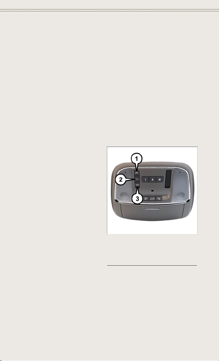
POWER SUNROOF
The power sunroof switch is located on the overhead console.
Opening Sunroof
Express Open
• Press the switch rearward and release
it within one-half second. The sunroof
will fully open and stop automatically.
Manual Open
• Press and hold the switch rearward to
open the sunroof. Any release of the
switch will stop the movement, and the
sunroof will remain in a partially open
position until the switch is pressed
again.
Venting Sunroof
• Press and release the button and the
sunroof will open to the vent position.
This is called “Express Vent” and will
occur regardless of sunroof position. During Express Vent operation, any movement of the switch will stop the sunroof.
1 — Opening Sunroof
2 — Venting Sunroof
3 — Closing Sunroof
Power Sunroof Switch
44

OPERATING YOUR VEHICLE
Closing Sunroof
Express Closing
• Press the switch forward and release it within one-half second. The sunroof will
fully close automatically from any position.
Manual Closing
• Press and hold the switch forward to close the sunroof. Any release of the switch
will stop the movement, and the sunroof will remain in a partially closed position
until the switch is pressed again.
COMMANDVIEW® SUNROOF WITH POWER SHADE
The CommandView®sunroof with power shade switch is located on the overhead
console.
NOTE:
The CommandView
function exactly the same as the power
sunroof. Refer to “Opening Sunroof,
Venting Sunroof and Closing Sunroof” in
“Power Sunroof”.
Opening Power Shade
Express
• Press the shade switch rearward and
release it within one-half second and
the shade will automatically open to
the halfway position and stop automatically.
• Press the switch a second time from
the halfway position and the shade will
automatically open to the full open
position and stop automatically.
®
sunroof switches
1 — Opening Sunroof
2 — Venting Sunroof
3 — Closing Sunroof
4 — Opening Shade
5 — Closing Shade
45

OPERATING YOUR VEHICLE
Manual
• To open the shade, press and hold the switch rearward. The shade will open and
stop automatically at the half-open position.
• Press and hold the shade switch rearward again and the shade will open
automatically to the full-open position.
NOTE:
Any release of the switch will stop the movement and the shade will remain in a
partially opened condition until the switch is pushed and held rearward again.
Closing Power Shade
Express
• Press the switch forward and release it within one-half second and the shade will
close automatically from any position.
Manual
• To close the shade, press and hold the switch in the forward position.
NOTE:
Any release of the switch will stop the movement and the shade will remain in a
partially closed condition until the switch is pushed and held forward again.
Pinch Protection Feature
This feature will detect an obstruction in the opening of the sunroof during Express
Close operation. If an obstruction in the path of the sunroof is detected, the sunroof
will automatically retract. Remove the obstruction if this occurs. Next, press the
switch forward and release to Express Close.
NOTE:
If three consecutive sunroof close attempts result in Pinch Protect reversals, the
fourth close attempt will be a Manual Close movement with Pinch Protect disabled.
46

OPERATING YOUR VEHICLE
WARNING!
• Do not let children play with the sunroof. Never leave children unattended in a
vehicle, or with access to an unlocked vehicle. Do not leave the Key Fob in or
near the vehicle, and do not leave the ignition of a vehicle equipped with
Keyless Enter-N-Go™ in the ACC or ON/RUN mode. Occupants, particularly
unattended children, can become entrapped by the power sunroof while
operating the power sunroof switch. Such entrapment may result in serious
injury or death.
• In a collision, there is a greater risk of being thrown from a vehicle with an open
sunroof. You could also be severely injured or killed. Always fasten your seat
belt properly and make sure all passengers are properly secured.
• Do not allow small children to operate the sunroof. Never allow your fingers,
other body parts, or any object to project through the sunroof opening. Injury
may result.
WIND BUFFETING
Wind buffeting can be described as a helicopter-type percussion sound. If buffeting
occurs with the rear windows open, adjust the front and rear windows together.
If buffeting occurs with the sunroof open, adjust the sunroof opening, or adjust any
window. This will minimize buffeting.
47

ELECTRONICS
YOUR VEHICLE'S SOUND SYSTEM
1. Uconnect®Phone Button pg. 105
®
2. Uconnect
3. Phone Hang Up Button pg. 105
4. Steering Wheel Audio control (Right) pg. 114
5. Steering Wheel Audio control (Left) pg. 114
6. Volume/Mute Knob
7. Assist Button pg. 57
48
Voice Command Button pg. 69

ELECTRONICS
8. Emergency 911 Button pg. 57
®
9. Uconnect
10. Uconnect
11. Uconnect
12. Tune/Scroll Knob/Browse/Enter Button
13. Media Hub: Audio Jack, USB Port, and SD Card Slot (located inside front
console) pg. 68
14. CD Player Inside Center Console pg. 67
Radio pg. 50
®
Radio Screen Off Button
®
Radio Back Button
49

ELECTRONICS
IDENTIFYING YOUR RADIO
Uconnect® 5.0
• 5” Touchscreen
• Three hard-keys on either side of the
display
Uconnect® 8.4A
• 8.4” Touchscreen
• Climate soft-key in lower menu bar
Uconnect® 5.0
50
Uconnect® 8.4A

ELECTRONICS
Uconnect® 8.4AN
• 8.4” Touchscreen
• Climate soft-key in lower menu bar
Uconnect® 8.4AN
Uconnect® ACCESS
Uconnect® Access — If Equipped (Available On Uconnect® 8.4AN)
WARNING!
ALWAYS drive safely with your hands on the steering wheel. You have full
responsibility and assume all risks related to the use of the Uconnect
and applications in this vehicle. Only use Uconnect
Failure to do so may result in an accident involving serious injury or death.
®
Uconnect
your vehicle with a built-in cellular connection. With Uconnect
• Place a call to a local 911 Operator for emergency assistance.
• Remotely lock/unlock your doors and start your vehicle from virtually anywhere,
using the Uconnect
logging into Mopar Owner Connect, or by calling Uconnect
within the United States and have network coverage).
• Turn your vehicle into a WiFi Hotspot and connect your devices to the internet.
• Receive text or email notifications if your vehicle's theft alarm goes off.
• Receive stolen vehicle assistance, using GPS technology to help authorities locate
your vehicle if it is stolen.
• Listen to your text messages or send free-form text messages with your voice while
keeping your hands on the wheel, using the Voice Texting feature. Requires a cell
phone that supports Bluetooth Message Access Profile (MAP).
Access enhances your ownership and driving experience by connecting
®
Access App for your smartphone. You can also do so by
®
when it is safe to do so.
®
®
Care. (Vehicle must be
®
features
Access, you can:
51

ELECTRONICS
• Search for places to eat, shop, relax and play with Yelp®, using your voice or
on-screen menu. Then navigate to them (navigation standard on Uconnect
8.4AN, optional on Uconnect®8.4A).
• Get operator assistance using the Assist button on your mirror.
Before you drive, familiarize yourself with the easy-to-use Uconnect® System.
1. The ASSIST and 9-1-1 buttons are located on your rearview mirror. The ASSIST
Button is used for contacting Roadside Assistance, Vehicle Care and Uconnect
Care. The 9-1-1 Button connects you to emergency services.
NOTE:
Vehicles sold in Canada and Mexico DO NOT have 9-1-1 Call system capabilities. 9-1-1
or other emergency line operators in Canada and Mexico may not answer or respond to
9-1-1 system calls.
®
2. The Uconnect
“Apps” button on the menu bar at the bottom right corner of the
radio touchscreen. This is where you can begin your registration process, manage
your Apps and purchase WiFi on demand.
®
3. The Uconnect
Voice Command and Uconnect®Phone buttons are located on the
left side of your steering wheel. These buttons let you use your voice to give
commands, make phone calls, send and receive text messages hands-free, enter
navigation destinations, and control your radio and media devices.
Included Trial Period For New Vehicles
Your new vehicle may come with an included trial period for use of the Uconnect
Access Services starting at the date of vehicle purchase (date based on vehicle sales
notification from your dealer). To activate the trial, you must first register with
Uconnect® Access. After the trial period, if you wish to continue your Uconnect
Access Services you can choose to purchase a subscription.
Features And Packages
• After the trial period, you can subscribe to continue your service by visiting
®
the Uconnect
Store located within the Mopar Owner Connect website
(moparownerconnect.com). If you need assistance, U.S. residents can call
®
Uconnect
Care at 855-792-4241.
• For the latest information on packages and pricing information: U.S. residents
visit DriveUconnect.com.
Uconnect® Access Registration (Uconnect® 8.4AN Only, U.S. 48 Contiguous States And Alaska)
NOTE:
Should you require assistance anytime during the registration process, simply call
®
Uconnect
Care at 855-792-4241.
1. From the parked vehicle with the radio touchscreen powered on, select the
“Apps” button on the touchscreen located near the bottom right-hand corner.
2. Press “Register” if you see a reminder screen or select “Uconnect Registration”
under the 'Favorites' tab.
®
®
®
®
52

ELECTRONICS
3. The Uconnect®Access Registration App will open and display step-by-step
instructions to start your registration.
4. Enter your email address into the radio touchscreen.
5. A message will display on the touchscreen indicating your email submission was
accepted.
6. At home, or wherever you access your email, look for an email from Uconnect
Access that contains your personalized registration link. If you don't see it, check
your spam or junk email folder. Open the email and click on the link to continue
registering online.
NOTE:
For security reasons, this link is valid for 72 hours from the time you submit your
email address into the radio touchscreen. If the link has expired, start the process
over (see step 1).
®
7. You are now registered for your Uconnect
the next time you start your vehicle. It may take over 30 minutes for all of the
Apps to install. If the Apps have not appeared after 72 hours, please contact
®
Uconnect
8. Get to know Uconnect
Care at 855-792-4241.
®
Access! We recommend:
• Go to moparownerconnect.com and log in using the email address and password
you established while registering. Go to the Learn & Use tab for complete
information on using Uconnect
®
• If you have a smartphone, download the Uconnect
Via Mobile features. See instructions below.
Download The Uconnect® Access App
If you own a compatible Apple or Android®powered device, the Uconnect Access
App allows you to remotely lock or unlock your doors, start your engine or activate
your horn and lights from virtually anywhere (Vehicle must be within the United
States and have network coverage). You can download the App from Mopar Owner
Connect or from the Apple App or Google Play store. For Uconnect
compatibility - visit UconnectPhone.com or call 1–877–855–8400.
Set Up Your Via Mobile Profile — If Equipped
Setting up your Via Mobile profile means entering your login information for each app
so that they can work in your vehicle. Complete your Via Mobile Profile online during
®
registration of your Uconnect
Access system. Access this page by logging into your
Mopar Owner Connect account (moparownerconnect.com), going to Edit Profile,
then Via Mobile Profile.
If you already have an account with these apps, click “SetUp” to enter your
information. If you do not have an account, you can create a new one.
Access Trial! Apps will be downloaded
Access.
®
Access App and set up your
®
phone
®
53

ELECTRONICS
Aha™ by HARMAN (www.aharadio.com)
• Enter your email address and password for Aha™, or create a new Aha™ account.
• You can link your Facebook, Twitter or Slacker accounts on the Aha™ website.
iHeartRadio (www.iheart.com)
• Click “Sign Up” if you’re new to iHeartRadio, or “Log In” to enter your iHeartRadio
account information.
• Select “Activate” to continue,
• Select “Close” to complete activation.
Pandora® (www.pandora.com)
®
• Enter your Pandora
Slacker Radio (www.slacker.com)
• Enter your Slacker username/email address and password, then click “Save.”
Invite family and friends to use the Via Mobile Apps in your vehicle by setting up their
own Via Mobile profile.
Renewing Subscriptions And Purchasing WiFi Hotspot (Uconnect® 8.4AN Only, U.S. 48 Contiguous States And Alaska)
Subscriptions, and WiFi Hotspot, can be purchased from the Uconnect®Store within
your vehicle, and online at Mopar Owner Connect. If you need help press the ASSIST
button on the rearview mirror, then select Uconnect
Purchasing Online
You can renew your subscription to a package or purchase WiFi from the Mopar Owner
Connect website. You must first set up a Uconnect
Log into moparownerconnect.com, select Edit Profile, then Uconnect
Account.
1. Log In to the Mopar Owner Connect website (moparownerconnect.com) with your
username/email and password.
2. Click on the “Shop” tab, then click on the Uconnect
3. From the Uconnect
4. This will launch the selected item into purchase mode along with providing
additional information. The purchase process begins when you press the “Buy”
button on the touchscreen.
5. The Uconnect
financial details of your purchase. Press the “Purchase” key to continue.
username/email address and password, then click “Save.”
®
Care (or dial 855-792-4241).
®
Access Payment Account online.
®
Store.
®
Store, select the item you wish to purchase.
®
Store will display a “Purchase Overview” message confirming the
®
Payment
54

ELECTRONICS
6.
The Uconnect®Store will ask you to “Confirm Payment” using your default payment
method on file in your Payment Account. Press the “Complete” key to continue.
7. The Uconnect®Payment Account will then ask for your “Payment Account PIN,”
which you established when setting up your Uconnect
entering this four digit PIN, press the “Complete” key to make the purchase.
8. You will receive a confirmation message that your purchase has been submitted.
Press the OK button to end the process.
Purchasing WiFi Hotspot While In Your Vehicle
®
You must set up a Uconnect
Access Payment Account online (log in to
moparownerconnect.com, go to Edit Profile, then Uconnect
set up and manage your Payment Account).
1. To purchase WiFi while in your vehicle, ensure the vehicle is running and in Park.
Press the Apps button on the touchscreen, then select WiFi within the Tools
menu. Follow the on-screen instructions. When asked for your payment PIN, use
the 4-digit PIN you established when setting up your payment account on Mopar
Owner Connect.
NOTE:
®
This may be different than the Uconnect
Security PIN you established for using
features such as Remote Vehicle Start. After purchasing WiFi, it may take up to
30 minutes (with the vehicle running) before the WiFi will be active in your vehicle.
2. Select WiFi again, then note the hotspot name. Select this network when
connecting devices to the hotspot. Also click on View/Edit Passphrase, then note
the security passphrase you will need to connect to the network on each device.
If your devices cannot see the WiFi Hotspot network after 30 minutes, please contact
®
Uconnect
Care by pressing the Assist button on the rear view mirror, or by calling
855-792-4241.
Using Uconnect® Access
Getting Started With Apps
Applications (Apps) and features in your Uconnect
that are customized for the driver and are certified by Chrysler Group, LLC. Two
different types are:
1. Built-In Features — use the built-in 3G Cellular Network on your Uconnect
or 8.4AN radio.
2. Uconnect® Access via Mobile (if equipped) — uses the Uconnect Access app and
your smartphone's data plan to access your personal Pandora
Aha™ and Slacker accounts from the vehicle and control them using the vehicle
touchscreen. Customer's data plan charges will apply.
®
payment account. After
®
Payment Account,to
®
Access system deliver services
®
®
, iHeartRadio,
8.4A
55

ELECTRONICS
Get started with your Uconnect®Access apps by pressing the Uconnect®“Apps”
button on the menu bar at the bottom right corner of the radio touchscreen. Available
apps and features are organized by the tabs on the left of the screen:
Favorite Apps — This is the default screen when you first press the “Apps” button on
the touchscreen, and is a good place to put the apps you use most frequently.
To make an App a “favorite”, press the “settings” button on the touchscreen to the
right of the app, and select “Make a favorite.”
All Apps — Organizes your Uconnect
Running Apps — Press this tab to see which apps are currently running.
®
Access apps (when available).
Favorite Apps
Maintaining Your Uconnect® Access Account
Reinstalling An App (Uconnect® 8.4AN Only)
You can easily correct many Application related issues you may be experiencing by
resetting the App back to the factory setting. From the vehicle’s radio touchscreen,
complete the following steps:
®
1. Press the “Uconnect
2. In My Apps, select “Settings,” then “Reinstall App.” Press “Continue.”
3. Your Apps have been successfully re-installed.
Canceling Your Subscription
Should you want to cancel your subscription, you can remove your account information using the same procedure contained in the Selling Your Vehicle section.
App” and open the Uconnect®Store. Go to My Apps.
56

ELECTRONICS
Selling Your Vehicle
When you sell your vehicle, we recommend that you remove your Uconnect
Account information from the vehicle. You can do this using the radio touchscreen in
the vehicle (Uconnect® 8.4AN only) or on the Mopar Owner Connect website
(moparownerconnect.com). Removing your account information cancels your subscription and makes your vehicle factory-ready for a new owner/subscriber.
From your vehicle’s radio touchscreen, select “Uconnect®Store” from the Apps Menu.
1.
2. Select “My Apps,” then “Settings.” Press “Remove Uconnect®Account.”
®
3. Enter your Uconnect
Uconnect Account.”
For additional information on Uconnect
• U.S. residents - visit DriveUconnect.com or call 1-877-855-8400.
• Canadian Residents - visit DriveUconnect.ca or call, 1-800-465-2001 (English)
or 1-800-387-9983 (French).
Security PIN, select “Proceed to Remove Vehicle from
®
:
Built-In Features (Uconnect® 8.4A And 8.4AN Only)
1. Assist Call – The rear view mirror contains an ASSIST push button which (once
registered) automatically connects the vehicle occupants to one of these predefined destinations for immediate support:
• Roadside Assistance Call —Ifyou
get a flat tire, or need a tow, you’ll
be connected to someone who can
help anytime. Additional fees may
apply. Additional information in
this section.
• Uconnect® Access Care —Inve-
hicle support for Uconnect
System, Apps and Features.
• Vehicle Care — Total support for
your Chrysler Group LLC vehicle.
2. Emergency 9-1-1 Call (If Equipped) —
The rear view mirror contains a 9-1-1 button that, when pressed, will place a call to
a local 9-1-1 operator to request help from local police, fire or ambulance personnel
in the event of an emergency. If this button is accidentally pressed, you will have
10 seconds to cancel the call. To cancel, press the 9-1-1 Call button again or press
the “cancellation button” shown on the touchscreen. After 10 seconds has passed,
the 9-1-1 call will be placed and only the 9-1-1 operator can cancel it. The LED
light on the rearview mirror will turn green once a connection to a 9-1-1 operator
has been made. The green LED light will turn off once the 9-1-1 call is terminated.
Have an authorized dealer service the vehicle if the rearview mirror light is
continuously red.
you understand and agree that 9-1-1 operators may, like any other 9-1-1 call, record
conversations and sounds in and near your vehicle upon connection.
If a connection is made between a 9-1-1 operator and your vehicle,
®
Access
Interior Rearview Mirror
®
Access
57

ELECTRONICS
3. Roadside Assistance (If Equipped) — If your vehicle is equipped with this feature
and within wireless range, you may be able to connect to Roadside Assistance by
pressing the “Assist” button on the rearview mirror. You will be presented with
Assist Care options. Make a selection by touching the prompts displayed on the
radio. If Roadside Assistance is provided to your vehicle, you agree to be
responsible for any additional roadside assistance service costs that you may
incur. In order to provide Uconnect®Services to you, we may record and monitor
your conversations with Roadside Assistance, Uconnect
whether such conversations are initiated through the Uconnect
vehicle, or via a landline or mobile telephone, and may share information
obtained through such recording and monitoring in accordance with regulatory
requirements. You acknowledge, agree and consent to any recording, monitoring
or sharing of information obtained through any such call recordings.
4. Yelp® — Customers have the ability to search for nearby destinations or a point
of interest (POI) either by category or custom search by using keywords (for
example, “Italian restaurant”). Searching can be done by voice or using the
touchscreen keypad. Using the touchscreen, launch Yelp
“Apps” icon, touch the “All Apps” tab, and then touch “Yelp.” Using voice
recognition press the Voice Command (VR) button on the steering wheel and say
®
“Launch Yelp
.”
5. Security Alarm Notification — The Security Alarm Notification feature notifies you
via email or text (SMS) message when the vehicle’s factory-installed security
alarm system has been set-off. There are a number of reasons why your alarm may
have been triggered, one of which could be that your vehicle was stolen. If so,
please see the details of the Stolen Vehicle Assistance service below. When you
register, Security Alarm Notification is automatically set to send you an email at
the mail address you provide should the alarm go off. You may also opt to have a
text message sent to your mobile device.
6. Stolen Vehicle Assistance — If your vehicle is stolen, contact local law enforce-
ment immediately to file a stolen vehicle report. Once this report has been filed,
®
Uconnect
care can help locate your vehicle. The Uconnect®Care agent will ask
for the stolen vehicle report number issued by local law enforcement. Then, using
GPS technology and the built-in wireless connection within your vehicle, the
®
Uconnect
Care agent will be able to locate the stolen vehicle and work with law
enforcement to help recover it. (Vehicle must be within the United States, have
network coverage and must be registered with Uconnect
subscription that includes the applicable feature).
7. WiFi Hotspot — WiFi Hotspot is on-demand WiFi 3G connectivity that's built-in
and ready to go whenever you are. Once your vehicle is registered for Uconnect
Access, you can purchase a Wifi Hotspot subscription at the Uconnect®Store.
After you've made your purchase, turn on your signal and connect your devices.
It's never been easier to bring your home or office with you.
Your vehicle must have a working electrical system for any of the in vehicle Uconnect
features to operate.
®
Care or Vehicle Care,
®
Services in your
®
by selecting the
®
Access with an active
®
®
58

ELECTRONICS
Uconnect® Access Remote Features
If you own a compatible iPhone®or Android®powered device, the Uconnect®Access
App allows you to remotely lock or unlock your doors, start your engine or activate your
horn and lights from virtually anywhere (Vehicle must be within the United States and
have network coverage). You can download the App from Mopar Owner Connect or from
the App Store (iPhone) or Google Play store. Visit UconnectPhone.com to determine
if your device is compatible. For Uconnect
if your device is compatible.
U.S. residents - visit UconnectPhone.com or call 1–877–855–8400
Remote Start — This feature provides the ability to start the engine on your vehicle,
without the keys and from virtually any distance. You can send a request to your
vehicle in one of two ways:
®
1. Using the Uconnect
Access App from a compatible smartphone.
2. From the Mopar Owner Connect website.
• You can also send a command to turn-off an engine that has been remote
started.
• After 15 minutes if you have not entered your vehicle with the key, the engine
will shut off automatically.
• This remote function requires your vehicle to be equipped with a factoryinstalled Remote Start system. To use this feature after the Uconnect
App is downloaded, login with your user name and Uconnect
• You can set-up notifications for your account to receive an email or text (SMS)
message every time a command is sent. Login to Mopar Owner Connect
(moparownerconnect.com) and click on Edit Profile to manage Uconnect
Notifications.
Remote Door Lock/Unlock — This feature provides the ability to lock or unlock the door
on your vehicle, without the keys and from virtually any distance. You can send a
request to your vehicle in one of three ways:
®
1. Using the Uconnect
Access App from a compatible smartphone.
2. From the Mopar Owner Connect website.
3. By contacting the Uconnect
®
To use this feature after the Uconnect
®
user name and Uconnect
Security PIN. Press the “App” button on your smartphone
with the closed lock icon to lock the door, and press the “open lock” icon to unlock
the driver’s door.
You can set-up notifications for your account to receive an email or text (SMS) message
every time a command is sent. Login to Mopar Owner Connect (moparownerconnect.com)
and click on Edit Profile to manage Uconnect
®
Phone customer support and to determine
®
Care on the phone.
®
Access App is downloaded, login using your
®
Notifications.
®
Access
Security PIN.
®
59

ELECTRONICS
Remote Horn And Lights — It’s easy to locate a vehicle in a dark, crowded or noisy
parking area by activating the horn and lights. It may also help if you need to draw
attention to your vehicle for any reason. You can send a request to your vehicle in one
of three ways:
®
1. Using the Uconnect
2. From the Mopar Owner Connect website.
3. By contacting the Uconnect
To use this feature after the Uconnect
user name and Uconnect
account to receive an email or text (SMS) message every time a command is sent.
Login to Mopar Owner Connect (moparownerconnect.com) and click on Edit Profile
to manage Uconnect
Voice Texting (U.S. Residents Only) — Want to dictate a personal message? Register
with Uconnect
®
Access to take advantage of a new, cloudbased Voice Texting service,
an enhancement to Voice Text Reply.
Voice Texting allows you to compose a new text or reply to an incoming text message.
Before you attempt to use the Voice Texting feature, check to ensure you have the
following:
1. A paired, Bluetooth
all Bluetooth
®
Visit UconnectPhone.com for system and device compatibility information.
2. An active Uconnect
the lower right hand corner of the touchscreen to begin the registration process.
3. Accept the Allow MAP profile request on your smart phone. (Please refer to device
manufacturer instructions for details).
To Send A Text Message:
1. Press the “Uconnect
2. Wait for the beep.
3. Say “Text.”
®
4. Uconnect
will prompt you “Say the phone number, or full name and phone type
of the contact you want to send a message to.”
5. Wait for the beep and say a contact that is in your phonebook, or a mobile phone
number that you would like to send the message to.
®
6. Uconnect
will prompt you “Please say the message that you would like to send.”
(If you do not hear this prompt, you may not have an active subscription with
®
Uconnect
Access).
Access App from a compatible smartphone.
®
Care on the phone.
®
®
Security PIN. You can set-up notifications for your
®
Notifications.
®
enabled phone with the Message Access Profile (MAP). Not
Access App is downloaded, login using your
enabled phones support MAP, including all iPhones®(Apple iOS).
®
Access trial or paid subscription. Press the “U” button on
®
Phone” button.
60

ELECTRONICS
7. Wait for the beep, and then dictate any message up to 140 characters. If you
exceed 140 characters, you will hear the following prompt: “Message was too
long; your message will be truncated.”
®
8. Uconnect
9. Uconnect
the current message and start over, say “Start Over”; to send the current message,
say “Send”; to hear the message again, say “Repeat”.
10. If you are happy with your message and would like to send it, wait for the beep
and say “Send”.
11. Uconnect
Sample Commands For Voice Text Reply And Voice Texting
“Listen to/view (message number four,
“Forward text/message to “John Smith”
will then repeat the message back to you.
®
will prompt you: “To add to your message, say “Continue”; To delete
®
will then say “Sending your message.”
Example Command Action
“Text John Smith”
“Text 123 - 456 - 7890”
“Show messages”
for example)”
“Reply”
“Forward text/message to
“123 - 456 - 7890”
Send a message to specific contact in
Send 123 - 456 - 7890 a message
See recent text messages listed by
Forward current text to specific
Forward current text to specific
address book
from your phonebook
®
screen
®
number on Uconnect
Hear messages or read it on
Uconnect
Send a voice text reply to a
current message
contact in address book
phone number
screen
Uconnect® Access Via Mobile (If Equipped — Available On Uconnect® 8.4A And Uconnect® 8.4AN)
Uconnect®Access via Mobile offers additional apps such as Aha™, iHeartRadio,
®
Pandora
Uconnect
and Slacker Radio. It uses your smartphone’s existing data plan to access
®
System-enabled apps, which you can control using both your touchscreen
and steering wheel controls. Customer’s data plan charges will apply.
To get started using Via Mobile apps, first register your Uconnect
®
Access system
where you'll be guided through the setup of your Via Mobile (requires a compatible
®
Android or iPhone
smartphone). Please refer to “Uconnect®Access Registration”
for more information.
61

ELECTRONICS
The Uconnect®Access app is compatible with select iPhone®and Android smartphones. Visit UconnectPhone.com to confirm that your smartphone is compatible
with Uconnect
vehicle touchscreen via Bluetooth
USB cable may also be supported for the data connection.
Launch the Uconnect®Access App on your smartphone, and login with your username
and password that was set up during registration. Accept the Terms and Conditions.
•
Ensure that Via Mobile data has been turned on under “Settings” in the Uconnect
Access App.
• A green indicator next to the words Via Mobile will show when it is ready to provide
data to the radio (a blue indicator when data is being sent). A red indicator means
that it is not ready to provide data.
®
. Once you’ve confirmed your smartphone is compatible, pair it to the
®
to use Via Mobile apps. If using an iPhone®,a
®
Each time you want to use a Via Mobile app in your vehicle, the Uconnect Access App
must be running on your smartphone and the smartphone must be paired via
Bluetooth
®
.
62

ELECTRONICS
If equipped, the Via Mobile apps can be found by selecting the “Apps” soft-key in the
lower right corner of the radio touchscreen. Via Mobile apps are listed under the “All
Apps” tab. The words “Via Mobile” will appear after the app name indicating it is a
Via Mobile app.
Via Mobile apps can also be launched through Voice Recognition by pressing the
VR button on the steering wheel and stating “launch” and then the name of the app.
For example, you can say “launch Aha via Mobile.”
NOTE:
For detailed information on how to use Via Mobile apps visit the Mopar Owner
Connect website (www.moparownerconnect.com) and login using the username and
password you set up when registering for Uconnect
A message will be displayed to remind you that Via Mobile apps utilize the data plan
on your connected smartphone to provide content. Many smartphones have a limit to
how much data they can utilize before incurring additional charges. The amount of
data being used varies by smartphone device, cellular service provider and specific
app. Check your mobile phone service plan for more details.* Touch “OK” to continue
or the “X” to exit.
(*Additional smartphone data usage charges may apply.)
®
Access.
63

ELECTRONICS
Determine If Your Vehicle Is Via Mobile-Enabled
To see if your Uconnect®8.4A or 8.4AN system is equipped with Via Mobile, press
the “Apps” button on the touchscreen, then press the “All Apps” tab on the left side
of the touchscreen. If you see Aha™, iHeartRadio, Pandora
system is capable of playing Via Mobile apps (registration required).
Earlier vehicles with Uconnect
enable Via Mobile. Call Uconnect Care at 855-792-4241 and please have the last
eight characters of your Vehicle Identification Number (VIN) available, or visit:
DriveUconnect.com/features/via-mobile/
• Click on Help & Support > Select your Brand > System Updates
®
8.4A or 8.4AN may qualify for a software upgrade to
Via Mobile Apps — If Equipped
• Aha™ by HARMAN — Aha™ by HARMAN makes it easy to instantly access your
favorite Web content on the go. Choose from over 40,000+ stations spanning
internet radio, personalized music, news, entertainment, hotels, weather, audiobooks, Facebook
• iHeartRadio — iHeartRadio provides instant access to more than 1,500 live radio
stations from across the country and allows listeners to create custom music
stations inspired by their favorite artists or songs.
• Pandora® — Pandora
anywhere. Personalized stations launch instantly, with the input of a favorite artist,
track, comedian, or genre.
• Slacker Radio — Enjoy millions of songs and hundreds of handcrafted stations.
NOTE:
For detailed information on how to use Via Mobile apps visit the Mopar Owner
Connect website (moparownerconnect.com) and log in using the username and
password you set up when registering for Uconnect
®
, Twitter®, and more.
®
gives people the music and comedy they love anytime,
®
Access.
®
and Slacker then your
64

Uconnect® 5.0
ELECTRONICS
Uconnect® 5.0
Setting The Time
1. Press the “MORE” hard-key on the right side of the display, next press the
“Settings” soft-key and then the “Time” soft-key. OR Press the “Settings”
hard-key on the right side of the display, then press the “Clock” soft-key. The Time
setting screen is displayed and the clock can be adjusted as described in the
following procedure.
NOTE:
In the Clock Setting Menu you can also select “Display Clock”. Display Clock turns
the clock display in the status bar on or off.
2. Touch the “Up” or “Down” arrows to adjust the hours or minutes, next select the
AM or PM soft-key. You can also select 12hr or 24hr format by touching the
desired soft-key.
3. Once the time is set press the “Done” soft-key to exit the time screen.
65

ELECTRONICS
Equalizer, Balance And Fade
1. Press the SETTINGS hard-key on the right side of the unit.
2. Then scroll down and press the “Audio” soft-key to get to the Audio menu.
The Audio Menu shows the following options for you to customize your audio settings.
3.
Equalizer
• Touch the “Equalizer” soft-key to adjust the Bass, Mid and Treble. Use the + or soft-key to adjust the equalizer to your desired settings. Press the “Back Arrow”
soft-key when done.
Balance/Fade
• Touch the “Balance/Fade” soft-key to adjust the sound from the speakers. Use the
arrow soft-key to adjust the sound level from the front and rear or right and left side
speakers. Touch the Center “C” soft-key to reset the balance and fade to the
factory setting. Press the “Back Arrow” arrow soft-key when done.
Speed Adjusted Volume
• Touch the “Speed Adjusted Volume” soft-key to select between OFF, 1, 2 or 3.
This will decrease the radio volume relative to a decrease in vehicle speed. Press
the “Back Arrow” soft-key when done.
Loudness
• Touch the “Loudness” soft-key to select the Loudness feature. When this feature
is activated it improves sound quality at lower volumes.
Surround Sound
• Touch the “Surround Sound” soft-key, select On or Off followed by pressing the
“Back Arrow” soft-key. When this feature is activated, it provides simulated
surround sound mode.
Radio Operation
Seek Up/Down Buttons
• Press to seek through radio stations in AM, FM or SXM bands.
• Hold either button to bypass stations without stopping.
Store Radio Presets
• When you are receiving a station that you wish to commit into memory, press and
hold the desired numbered soft-key for more than two seconds, or until you hear a
confirmation beep.
• The Radio stores up to 12 presets in each of the Radio modes. Four presets are
visible at the top of the radio screen. Touching the “all” soft-key on the radio home
screen will display all of the preset stations for that mode.
66

ELECTRONICS
SiriusXM Premier Over 160 Channels
• Get every channel available on your satellite radio, and enjoy all you want, all in
one place. Hear commercial-free music plus sports, news, talk and entertainment.
Get all the premium programming, including Howard Stern, every NFL game,
Oprah Radio
Stewart and more. And get 20+ extra channels, including SiriusXM Latino,
offering 20 channels of commercial free music, news, talk, comedy, sports and
more dedicated to Spanish language programming.
• To access SiriusXM Satellite Radio, press the RADIO hard-key and then the “SXM”
soft-key.
• SiriusXM services require subscriptions, sold separately after the 12-month trial
included with the new vehicle purchase. If you decide to continue your service at the
end of your trial subscription, the plan you choose will automatically renew and bill at
then-current rates until you call SiriusXM at 1-866-635-2349 for U.S. residents and
1-888-539-7474 for Canadian residents to cancel. See SiriusXM Customer Agreement
for complete terms at www.siriusxm.com for U.S. residents and www.siriusxm.ca for
Canadian residents. All fees and programming subject to change. Our satellite
service is available only to those at least 18 and older in the 48 contiguous USA
and D.C. Our Sirius satellite service is also available in PR (with coverage
limitations). Our Internet radio service is available throughout our satellite service
area and in AK and HI. ©2014 Sirius XM Radio Inc. Sirius, XM and all related
marks and logos are trademarks of Sirius XM Radio Inc.
Disc Operation
• Your vehicle may have a remote CD player located in the lower center console
storage bin.
• CD/Disc Mode is entered by either inserting a CD/Disc or by touching the “Media”
button located on the side of the display. Once in Media Mode, select “Disc”.
• Gently insert one CD into the CD player with the CD label facing as indicated on
the illustration located on the Disc player.
Seek Up/Down Buttons
• Press to seek through Disc tracks.
• Hold either button to bypass tracks without stopping.
Browse
• Touch the “Browse” soft-key to scroll through and select a desired track on the
Disc. Touch the “Exit” soft-key if you wish to cancel the browse function.
®
, every MLB®and NHL®game, every NASCAR®race, Martha
67

ELECTRONICS
USB/Audio Jack (AUX)/Bluetooth® Operation
USB/iPod®
®
• USB/iPod
into the USB port or by touching the “Media” hard-key located left of the display.
Once in Media Mode, touch the “Source” soft-key and select USB/iPod
•
Pressing the “Media” hard-key, then touch the “Source” soft-key and then select
“USB/iPod
allowing the music from your portable device to play through the vehicle's speakers.
Audio Jack (AUX)
• The AUX allows a portable device, such as an MP3 player or an iPod
plugged into the radio and utilize the vehicle’s audio system, using a 3.5 mm audio
cable, to amplify the source and play through the vehicle speakers.
• Pressing the “Media” hard-key, then touch the “Source” soft-key and then select
AUX to change the mode to auxiliary device if the audio jack is connected, allowing
the music from your portable device to play through the vehicle's speakers.
The functions of the portable device are controlled using the device buttons, not the
•
buttons on the radio. The volume may be controlled using the radio or portable device.
Bluetooth®
• If using a Bluetooth
your vehicle's sound system.
•
Press the “Media” hard-key, then touch the “Source” soft-key. Select “Bluetooth®”
to change the mode to Bluetooth
portable device to play through the vehicle's speakers.
Uconnect® 5.0 Available Media Hubs
Mode is entered by either inserting a USB Jump Drive or iPod®cable
®
” to change the mode to the USB device if the device is connected,
®
equipped device, you may also be able to stream music to
®
if the device is paired, allowing the music from your
Uconnect®5.0
Media Hub
(SD, USB, AUX Ports)
SO
Dual Charging Ports
®
®
,tobe
S = Standard Equipment
O = Optional Equipment
Voice Text Reply (Not Compatible With iPhone®)
Once your Uconnect®system is paired with a compatible mobile device, the system
can announce a new incoming text message, and read it to your over the vehicle audio
system. You can reply to the message using Voice Recognition, by selecting, or saying
one of the 18 pre-defined messages.
68

ELECTRONICS
• Here’s How: Press the Uconnect®Phone button and wait for the beep, then
®
say “reply.” Uconnect
will give the following prompt: “ Please say the message
you would like to send.” Wait for the beep and say one of the pre-defined
®
messages. (If you are not sure, you can say “help”). Uconnect
will then read the
pre-defined messages allowed. As soon as you hear the message you would like to
®
send, you can interrupt the list of prompts by pressing the Uconnect
®
button and saying the phrase. Uconnect
will confirm the message by reading it
phone
back to you. Then press the Phone button and say “Send.”
PRE-DEFINED VOICE TEXT REPLY RESPONSES
Yes. Stuck in Traffic. See you later.
No. Start without me. I’ll be Late.
Okay. Where are you?
Call me. Are you there yet?
I’ll call you later. I need directions.
I’m on my way.
I’m lost. Thanks.
Can’t talk right now.
I will be <number>
minutes late.
See you in <number>
of minutes.
NOTE:
Voice texting reply and voice texting features require a compatible mobile device
®
enabled with Bluetooth
smartphones do not currently support Bluetooth
Message Access Profile (MAP). iPhone®and some other
®
MAP. Visit UconnectPhone.com for
system and device compatibility.
• Want to dictate a personal message? You must first register with Uconnect
Access (U.S. residents only) to take advantage of a new, cloud-based Voice Texting
service, an enhancement to Voice Text Reply.
VOICE COMMAND QUICK REFERENCE
®
Uconnect® 5.0 Voice Command Quick Reference
• If the Uconnect®Voice Command button exists on your steering wheel,
you have the Voice Command feature, which is optimized for the driver. The Voice
Command feature lets you keep your hands on the wheel, and your eyes on the
road.
• When you press the Voice Command
button located on the steering wheel,
you will hear a beep. After the beep, give your command. If you do not know what
commands to say, you can say “help” and the system will provide options to you.
If you ever wish to interrupt the system while it lists options, press the Voice
Command
button, after the beep, say your command.
NOTE:
All phone oriented voice commands are accessible by first pressing the Phone Pick
Up
Phone Hang Up
button, not the Voice Command button. To end a call, simply press the
button. In some vehicle’s, the Phone Pickup button
serves the dual purpose of ending calls as well.
69

ELECTRONICS
Voice Command (VR) User TIPs
®
• To hear available commands, press the Uconnect
say “Help.” You will hear available commands for the menu displayed.
• At any time, you can say the words “Cancel” or “Help.” These commands are
universal and can be used from virtually any menu. All other specific commands
can be used depending upon the active application.
• You can interrupt the system prompts at any time by pressing the Uconnect
Command button while the system is speaking. After the beep, you can say a
command.
• You can chain commands together for faster results. Say “Call Joe Doe mobile”,
for example.
• For best performance, adjust the rearview mirror to provide at least ½ in (1 cm)
gap between the overhead console (if equipped) and the mirror.
• Always wait for the beep before speaking.
• Speak normally, without pausing, just as you would speak to a person sitting a few
feet/meters away from you.
• Make sure that no one other than you is speaking during a Voice Command period.
Steering Wheel Buttons
• You can control many of your radio
features using your voice. Press either
the VR
button on your steering wheel.
or Phone Pick Up
Voice Command button and
®
Voice
70
Steering Wheel Buttons

Radio Mode Media Mode Phone Mode
Media Devices Control -
Control
ELECTRONICS
Voice Text Reply
agement, Pre-defined
Call Initiation, Call Man-
GENERAL
“Go to Radio” (Media, Phone) – Compass, Settings, and More
functions are not Voice Command accessible
“Cancel”
“Help” (to listen to suggested commands specific to current need
“Repeat”
“Tune to AM950”, “Tune to 95.5FM (preset 5)
--
GENERAL
“Tune to Satellite Channel 80's on 8”, Tune to Satellite Channel
RADIO
32 (preset 4)
“Browse” (show) “artist” (albums, music)
MEDIA
“Show paired phones” (devices)
“Play song – Maple Leaf Rag” (artist - Scott Joplin, genre - rock,
album - Ragtime Favorites)
Steering Wheel Buttons to
AM/FM & Satellite Band
Voice
®
Press:
Uconnect
Phone
®
Uconnect
Command (VR) Button
Types of Voice Commands
Available
Pick Up Button
Voice Command Examples – Uconnect® 5.0
While In: Voice Command Example:
Anytime
AM/FM
Satellite Band Control
Media Devices Control (Functionality is dependent on compatibility
between devices and radio)
71

ELECTRONICS
Forward one of 18 pre-defined SMS messages to incoming calls/
text messages:
“Yes.”
“No.”
“Okay.”
“Dial 123-456-7890” (phone number)
PHONE
“Call John Smith mobile” (home, office, other)
“Redial”
“Show outgoing” (recent) “calls”
“Search for John Smith” (any contact name in address book)
“Show (display list) contacts”
“I can’t talk right now.”
“Call me.”
“I’ll call you later.”
“I’m on my way.”
“Thanks.”
“I’ll be late.”
“I will be <number> minutes late.”
“See you in <number> minutes.”
“Stuck in traffic.”
“Start without me.”
“Where are you?”
“Are you there yet?”
“I need directions.”
“I’m lost.”
“See you later.”
While In: Voice Command Example:
72
paired
®
Call Initiation (Requires that phone has been Bluetooth
with radio)
Call Management
and some
®
Message Access Profile (MAP). iPhone
®
Voice Text Reply (Radio audibly recognizes these 18 pre-defined
SMS messages as you speak).
NOTE: Requires a compatible mobile device enabled with
Bluetooth
MAP. Visit
®
www.UconnectPhone.com for system and device compatibility.
other smartphones do not currently support Bluetooth

Uconnect® 8.4A
Uconnect® 8.4A AT A GLANCE
ELECTRONICS
Uconnect® 8.4A
Displaying The Time
• If the time is not currently displayed on the radio or player main page, touch the
“Settings” soft-key (if equipped), or the “Apps” or “Controls” soft-key and then
the “Settings” soft-key. In the Settings list, touch the “Clock” soft-key then touch
the check box next to “Show Time” in Status Bar.
Setting The Time
• Model 8.4AN synchronizes time automatically via GPS, so it should not require
any time adjustment. If you do need to set the time manually, follow the
instructions below for Model 8.4A.
• For Model 8.4A, turn the unit on, then touch the “time display” at the top of the
screen. Touch “Yes”.
• If the time is not displayed at the top of the screen, touch the “Settings” soft-key
(if equipped), or the “Apps” or “Controls” soft-key and then the “Settings”
soft-key. In the Settings screen, touch the “Clock” soft-key, then check or uncheck
this option.
• Touch + or – next to Set Time Hours and Set Time Minutes to adjust the time.
• If these features are not available, uncheck the Sync with GPS box.
• Touch X to save your settings and exit out of the Clock Setting screen.
73

ELECTRONICS
Audio Settings
• Touch of the “Audio” soft-key to activate the Audio settings screen to adjust
Balance\Fade, Equalizer, and Speed Adjusted Volume.
• You can return to the Radio screen by touching the X located at the top right.
Balance/Fade
• Touch the “Balance/Fade” soft-key to Balance audio between the front speakers or
fade the audio between the rear and front speakers.
• Touching the “Front, Rear, Left, or Right” soft-keys or touch and drag the Speaker
Icon to adjust the Balance/Fade.
Equalizer
• Touch the “Equalizer” soft-key to activate the Equalizer screen.
• Touch the + or - soft-keys, or by touching and dragging over the level bar for each
of the equalizer bands. The level value, which spans between plus or minus 9, is
displayed at the bottom of each of the Bands.
Speed Adjusted Volume
• Touch the “Speed Adjusted Volume” soft-key to activate the Speed Adjusted
Volume screen. The Speed Adjusted Volume is adjusted by touching the + and buttons or by touching and dragging over the level bar. This alters the automatic
adjustment of the audio volume with variation to vehicle speed.
Surround Sound
• Touch the “Surround Sound” soft-key, select On or Off followed by pressing the
“arrow back” soft-key. When this feature is activated, it provides simulated
surround sound mode.
74

ELECTRONICS
RADIO
Uconnect® 8.4A Radio
• To access the Radio mode, touch the Radio soft-key at the lower left of the screen.
Selecting Radio Stations
• Touch the desired radio band (AM, FM or SXM) soft-key.
Seek Up/Seek Down
• Touch the Seek arrow soft-keys for less than two seconds to seek through radio
stations.
• Touch and hold either arrow soft-key for more than two seconds to bypass stations
without stopping. The radio will stop at the next listenable station once the arrow
soft-key is released.
Direct Tune
• Tune directly to a radio station by pressing the “Tune” button on the screen, and
entering the desired station number.
75

ELECTRONICS
Store Radio Presets
• Your radio can store 36 total preset stations, 12 presets per band (AM, FM and
SXM). They are shown at the top of your radio screen. To see the 12 preset stations
per band, press the arrow soft-key at the top right of the screen to toggle between
the two sets of six presets.
• To set a station into memory press and hold the desired numbered soft-key for
more than two seconds or until you hear a confirmation beep.
SiriusXM PREMIER OVER 160 CHANNELS
• Get every channel available on your satellite radio, and enjoy all you want, all in
one place. Hear commercial-free music plus sports, news, talk and entertainment.
Get all the premium programming, including Howard Stern, every NFL game,
Oprah Radio
Stewart and more. And get 20+ extra channels, including SiriusXM Latino,
offering 20 channels of commercial free music, news, talk, comedy, sports and
more dedicated to Spanish language programming.
• To access SiriusXM Satellite Radio, touch the “SXM” soft-key on the main Radio
screen.
• The following describes features that are available when in SiriusXM Satellite
Radio mode.
Seek Up/Seek Down
• Touch the “Seek” arrow soft-keys for less than two seconds to seek through
channels in SXM mode.
• Touch and hold either “arrow” soft-key for more than two seconds to bypass
channels without stopping. The radio will stop at the next listenable channel once
the “arrow” soft-key is released.
Direct Tune
• Tune directly to a SXM channel by pressing the “Tune” soft-key on the screen, and
entering the desired station number.
Jump
• Automatically tells you when Traffic & Weather for a favorite city is available, and
gives you the option to switch to that channel. Touch “Jump” to activate the
feature. After listening to Traffic and Weather, touch “Jump” again to return to the
previous channel.
®
, every MLB®and NHL®game, every NASCAR®race, Martha
76

ELECTRONICS
Fav
• Activates the favorites menu. You can add up to 50 favorite artists or songs. Just
touch “Add Fav Artist” or “Add Fav Song” while the song is playing. You will then
be alerted any time one of these songs, or works by these artists, is playing on other
SiriusXM channels.
SiriusXM Parental Controls
• You can skip or hide certain channels from view if you do not want access to them.
Touch the “More” soft-key, then the “Settings” soft-key, next touch the “Sirius
Setup” soft-key, then select “Channel Skip”. Touch the box, check-mark, next to
the channel you want skipped. They will not show up in normal usage.
• SiriusXM also offers the option to permanently block selected channels. Call
(1-888-601-6297 for U.S. customers, 1-877-438-9677 for Canadian customers) and request the Family - Friendly Package.
Browse
• Lets you browse the SiriusXM channel listing or Genre listing. Favorites, Game
Zone, Weather and Jump settings also provide a way to browse the SiriusXM
channel list.
Browse
Sub-Menu
All Shows the channel listing.
Genre Provides a list of all genres, and lets you jump to a channel within the
Presets Lets you scroll the list of Preset satellite channels. Touch the channel, or
Favorites Lets you manage artists and songs in the Favorites list and configure Alert
Game Zone Provides alerts when your favorite sports teams are starting a game which
Jump Lets you select your favorite cities for Traffic & Weather information,
Sub-Menu Description
selected genre.
press Enter on the Tune knob, to go to that channel. Touch the trash can
icon to delete a preset. Your presets are also shown at the top of the main
Satellite Radio screen.
Settings to let you know when favorite songs or artists are playing on other
channels. Also, view a list of channels airing any of your Favorites.
is being aired on other SiriusXM channels, or when their game score is
announced. You can select and manage your Teams list here, and
configure alerts.
which is used by the Jump feature on the main satellite radio screen.
77

ELECTRONICS
Replay
• Lets you replay up to 44 minutes of the content of the current SiriusXM channel.
Replay
Option
Play/Pause Touch to Pause content playback. Touch Pause/Play again to resume
Rewind/RW Rewinds the channel content in steps of five seconds. Touch and hold to
Fast
Forward/FW
Replay Time Displays the amount of time in the upper center of the screen by which
Live Resumes playback of Live content at any time while replaying rewound
• SiriusXM services require subscriptions, sold separately after the 12-month trial
included with the new vehicle purchase. If you decide to continue your service at the
end of your trial subscription, the plan you choose will automatically renew and bill at
then-current rates until you call SiriusXM at 1-866-635-2349 for U.S. residents and
1-888-539-7474 for Canadian residents to cancel. See SiriusXM Customer Agreement
for complete terms at www.siriusxm.com for U.S. residents and www.siriusxm.ca for
Canadian residents. All fees and programming subject to change. Our satellite
service is available only to those at least 18 and older in the 48 contiguous USA
and D.C. Our Sirius satellite service is also available in PR (with coverage
limitations). Our Internet radio service is available throughout our satellite service
area and in AK and HI. ©2014 Sirius XM Radio Inc. Sirius, XM and all related
marks and logos are trademarks of Sirius XM Radio Inc.
Option Description
playback.
rewind continuously, then release to begin playing content at that point.
Forwards the content, and works similarly to Rewind/RW. However, Fast
Forward/FW can only be used when content has been previously rewound.
your content lags the Live channel.
content.
Disc Operation
• Your vehicle may have a remote CD player located in the lower center console
storage bin.
• CD/Disc Mode is entered by either inserting a CD/Disc or by touching the “Media”
button located on the side of the display. Once in Media Mode, select “Disc”.
• Gently insert one CD into the CD player with the CD label facing as indicated on
the illustration located on the Disc player.
Seek Up/Down Buttons
• Press to seek through Disc tracks.
• Hold either button to bypass tracks without stopping.
Browse
• Touch the “Browse” soft-key to scroll through and select a desired track on the
Disc. Touch the “Exit” soft-key if you wish to cancel the browse function.
78

ELECTRONICS
MEDIA HUB – PLAYING iPod®/USB/MP3 DEVICES
• There are many ways to play music from iPod®/MP3 players or USB devices
through your vehicle's sound system.
Audio Jack (AUX)
®
• The AUX allows a portable device, such as an MP3 player or an iPod
plugged into the radio and utilize the vehicle’s sound system, using a 3.5 mm
audio cable, to amplify the source and play through the vehicle speakers.
• Touching the Media soft-key then choose AUX source will change the mode to
auxiliary device if the audio jack is connected, allowing the music from your
portable device to be heard through the vehicle's speakers. In order to activate the
AUX, plug in the audio jack.
• The functions of the portable device are controlled using the device buttons. The
volume may be controlled using the radio or portable device.
• To route the audio cable out of the center console, use the access cut out in the
front of the console.
USB Port
• Connect your iPod
®
or compatible device using a USB cable into the USB Port.
USB Memory sticks with audio files can also be used. Then, audio from the device
can be played on the vehicle’s sound system while providing metadata (artist, track
title, album, etc.) information on the radio display.
®
• When connected, the iPod
/compatible USB device can be controlled using the
radio or Steering Wheel Audio Controls to play, skip to the next or previous track,
browse, and list the contents.
®
• The iPod
battery charges when plugged into the USB port (if supported by the
specific device).
®
• To route the USB/iPod
cable out of the center console, use the access cut out.
NOTE:
®
• When connecting your iPod
device for the first time, the system may take several
minutes to read your music, depending on the number of files. For example, the
system will take approximately five minutes for every 1000 songs loaded on the
device. Also during the reading process, the Shuffle and Browse functions will be
disabled. This process is needed to ensure the full use of your iPod
only happens the first time it is connected. After the first time, the reading process
®
of your iPod
will take considerably less time unless changes are made or new
songs are added to the playlist.
The USB port supports certain Mini, Classic, Nano, Touch, and iPhone®devices. The
•
USB port also supports playing music from compatible external USB Mass Storage
®
Class memory devices. Some iPod
port features. Please visit Apple’s website for iPod
software versions may not fully support the USB
®
software updates.
SD Card
• Play songs stored on an SD card inserted into the SD card slot.
• Song playback can be controlled using the radio or Steering Wheel Audio Controls
to play, skip to the next or previous track, browse, and list the contents.
,tobe
®
features and
79
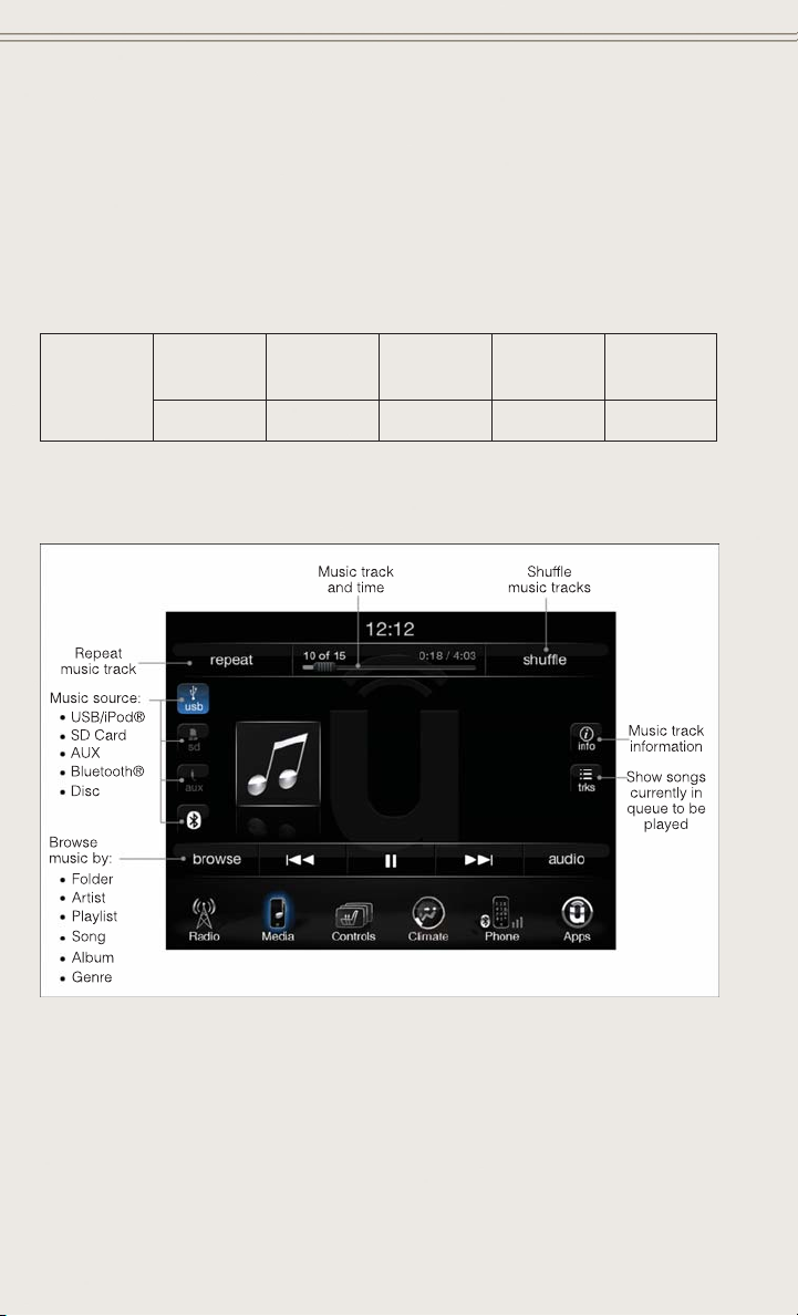
ELECTRONICS
Bluetooth® Streaming Audio
®
• If equipped with Uconnect
devices, cell phones or other media players, may also be able to stream music to
your vehicle's sound system. Your connected device must be Bluetooth
compatible, and paired with your system (see Uconnect
instructions). You can access the music from your connected Bluetooth
touching the Bluetooth
Media Hub
Uconnect
8.4A &
8.4AN
®
(USB, AUX
Ports)
-SSOO
S = Standard Equipment
O = Optional Equipment
iPod®/CD/AUX CONTROLS
Voice Command, your Bluetooth®-equipped iPod
®
Phone for pairing
®
soft-key while in Media mode.
Media Hub
(SD, USB,
AUX Ports)
Remote USB
Port (Fully
Functional)
Remote USB
Port (Charging Only)
®
device by
Dual Charg-
ing Ports
®
®
-
iPod®/CD/AUX Controls
The iPod®/CD/AUX controls are accessed by touching the desired soft-key displayed on
•
the side of the screen and choose between Disc, AUX, iPod
®
, Bluetooth®or SD Card.
NOTE:
®
Uconnect
will usually automatically switch to the appropriate mode when some-
thing is first connected or inserted into the system.
80

ELECTRONICS
NAVIGATION (DEALER-ACTIVATED OPTION)
• Your Uconnect®8.4A is “Navigation-Ready”, and can be equipped with Navigation at an extra cost. See your dealer for details.
• The information in this section is only applicable if the feature has been equipped.
If equipped, you will see a Nav soft-key at the bottom of the touchscreen.
Changing The Navigation Voice Prompt Volume
1. Touch the “Settings” soft-key.
2. In the Settings menu, touch the “Guidance” soft-key.
3. In the Guidance menu, adjust the Nav Volume by touching the + or – Nav Volume
Adjustment soft-keys.
Navigation Main
Finding Points Of Interest (POI)
• From the main Navigation menu, touch the Where To? soft-key, then touch the
Points of Interest soft-key.
• Select a Category and then a subcategory, if necessary.
• Select your destination and touch the Yes soft-key.
81

ELECTRONICS
Finding A Place By Spelling The Name
• From the Main Navigation Menu touch the “Where to?” soft-key, touch the “Points
of Interest” soft-key and then touch the “Spell” Name soft-key.
• Enter the name of your destination.
• Touch the “List” soft-key.
• Select your destination and touch the “Yes” soft-key.
Entering A Destination Address
• From the main Navigation menu touch the “Where To?” soft-key, then touch the
“Address” soft-key.
• Follow the on-screen prompts (country, state/province, city, street) to enter the
address and touch the “Yes” soft-key.
• Destination entry is not available while your vehicle is in motion. However, you can
also use Voice Command to enter an address while moving. See Voice Command
Tips for more information.
Setting Your Home Location
• Touch the “NAV” soft-key in the menu bar to access the Navigation system and the
Main Navigation menu.
• Touch the “Where To?” soft-key, then touch the “Go Home” soft-key.
• You may enter your address directly, use your current location as your home
address, or choose from recently found locations.
• To delete your Home location (or other saved locations) so you can save a new
Home location, touch the “Where To?” soft-key from the Main Navigation menu,
then touch the “Go Home” soft-key, and in the Yes screen touch the “Options”
soft-key. In the Options menu touch “Clear Home”. Set a new Home location by
following the previous instructions.
82

ELECTRONICS
Go Home
• A Home location must be saved in the system. From the Main Navigation menu,
touch the “Where To?” soft-key, then touch the “Go Home” soft-key.
Navigation
• Your route is marked with a blue line on the map. If you depart from the original
route, your route is recalculated. A speed limit icon could appear as you travel on
major roadways.
Adding A Stop
• To add a stop you must be navigating a route.
• Touch the “Menu” soft-key to return to the Main Navigation menu.
• Touch the “Where To?” soft-key, then search for the extra stop. When another
location has been selected, you can choose to cancel your previous route, add as
the first destination or add as the last destination.
• Touch the desired selection and touch the “Yes” soft-key.
Taking A Detour
• To take a detour you must be navigating a route.
• Touch the “Detour” soft-key.
NOTE:
If the route you are currently taking is the only reasonable option, the device might
not calculate a detour.
®
• For more information, see your Uconnect
Supplement Manual.
83

ELECTRONICS
Uconnect® Phone (Bluetooth® Hands Free Calling)
• If the Uconnect®Phone Button exists on your steering wheel, then you have
the Uconnect
• The Uconnect
tions system with Voice Command Capability (see Voice Command section).
• The Uconnect
using simple voice commands or using button on the touchscreen.
• Refer to the Understand The Features Of Your Vehicle section of your vehicle's
Owner's Manual on the DVD for further details.
NOTE:
The Uconnect
Hands-Free Profile, Version 1.0 or higher. For Uconnect®Customer Support:
• U.S. residents visit www.UconnectPhone.com or call 1-877-855-8400.
• Canadian Residents visit www.UconnectPhone.com or call, 1-800-465–2001
(English) or 1-800-387-9983 (French).
Pairing A Phone
• To use the Uconnect®Phone feature, you must first pair your Bluetooth®phone
with the Uconnect
Start Pairing Procedure On The Radio
• Touch the “Phone” soft-key and then the “Settings” soft-key. Next, touch “Add
Device”.
• Uconnect
connecting.
Start Pairing Procedure On Mobile Phone
• Search for available devices on your Bluetooth
usually within Settings or Options under “Bluetooth”. See your mobile phone’s
manual for details.
• When your phone finds the system, select “Uconnect” as the paired device. You
may be prompted by your phone to download the phonebook. This is so you can
make calls by saying the name of your contact (PBAP-Phone Book Access Profile).
Complete The Pairing Procedure
• When prompted on the phone, verify with radio password shown on the Uconnect
Screen.
• If your phone asks you to accept a connection request from Uconnect
“Yes”. If available, check the box telling it not to ask again – that way your phone
will automatically connect each time you start the vehicle.
®
Phone features.
®
Phone is a voice-activated, hands-free, in-vehicle communica-
®
Phone allows you to dial a phone number with your mobile phone
®
Phone requires a mobile phone equipped with the Bluetooth
®
system.
®
Phone will display an “In progress” screen while the system is
®
enabled mobile phone. This is
®
, select
®
®
84

ELECTRONICS
Select The Mobile Phone's Priority Level
• When the pairing process has successfully completed, the system will prompt you
to choose whether or not this is your favorite phone. Selecting “Yes” will make this
phone the highest priority. This phone will take precedence over other paired
phones within range. Only one phone can be paired at a time.
®
• You are now ready to make hands-free calls. Press the “Uconnect
on your steering wheel to begin.
Making A Phone Call
• Press the Uconnect®Phone button .
• After the BEEP, say “dial” then the number (or “call” then the name as listed in
your phone; see Phonebook).
NOTE:
You can also initiate a call by using the touchscreen on the Phone main screen.
Receiving A Call – Accept (And End)
• When an incoming call rings/is announced on Uconnect®, press the Phone
button
• To end a call, press the Hang Up or Phone button
.
.
Mute (Or Unmute) Microphone During Call
• During a call, press the “Mute” button on the touchscreen on the Phone main
screen to mute and unmute the call.
Transfer Ongoing Call Between Handset And Vehicle
• During an on-going call, touch the “Transfer” soft-key on the Phone main screen
to transfer an on-going call between handset and vehicle.
Common Phone Commands (Examples)
• “Call John Smith”
• “Call John Smith mobile”
• “Dial 1 248 555 1212”
• “Call Emergency”
• “Call Towing Assistance”
• “Redial”
Phone” button
85
ELECTRONICS
Phonebook
• Uconnect®radios automatically downloads your phonebook from your paired
phone, if this feature is supported by your phone. Entries are updated each time
that the phone is connected. If your phone book entries do not appear, check the
settings on your phone. Some phones require you to enable this feature manually.
• Your phonebook can be browsed on your radio screen, but editing can only be done
on your phone. To browse, touch the “Phone” soft-key, then the “Phonebook”
soft-key.
• Favorite phonebook entries can be saved as Favorites for quicker access. Favorites
are shown at the top of your main phone screen.
Voice Command Tips
• Using complete names (i.e; Call John Doe vs. Call John) will result in greater
system accuracy.
• You can “chain” commands together for faster results. Say “Call John Doe,
mobile”, for example.
• If you are listening to available voice command options, you do not have to listen
to the entire list. When you hear the command that you need, press the
button on the steering wheel, wait for the beep and say your command.
Changing The Volume
• Start a dialogue by pressing the Phone button , then say a command for
example - "Help".
• Use the radio ON/OFF VOLUME rotary knob to adjust the volume to a comfortable
level while the Uconnect
Uconnect
NOTE:
To access help, press the Uconnect
say "help." Touch the display or push either
to cancel the help session.
®
is different than the audio system.
Voice Text Reply (Not Compatible With iPhone®)
Once your Uconnect®system is paired with a compatible mobile device, the system
can announce a new incoming text message, and read it to your over the vehicle audio
system. You can reply to the message using Voice Recognition, by selecting, or saying
one of the 18 pre-defined messages.
• Here’s How: Press the Uconnect
say “reply.” Uconnect
you would like to send.” Wait for the beep and say one of the pre-defined
messages. (If you are not sure, you can say “help”). Uconnect
®
system is speaking. Please note the volume setting for
®
Phone button on the steering wheel and
or button and say "cancel"
®
®
will give the following prompt: “ Please say the message
Phone button and wait for the beep, then
®
will then read the
86

ELECTRONICS
pre-defined messages allowed. As soon as you hear the message you would like to
®
send, you can interrupt the list of prompts by pressing the Uconnect
®
button and saying the phrase. Uconnect
will confirm the message by reading it
phone
back to you. Then press the Phone button and say “Send.”
PRE-DEFINED VOICE TEXT REPLY RESPONSES
Yes. Stuck in Traffic. See you later.
No. Start without me. I’ll be Late.
Okay. Where are you?
Call me. Are you there yet?
I’ll call you later. I need directions.
I’m on my way.
I’m lost. Thanks.
Can’t talk right now.
I will be <number>
minutes late.
See you in <number>
of minutes.
NOTE:
Voice texting reply and voice texting features require a compatible mobile device
®
enabled with Bluetooth
smartphones do not currently support Bluetooth
Message Access Profile (MAP). iPhone®and some other
®
MAP. Visit UconnectPhone.com for
system and device compatibility.
• Want to dictate a personal message? You must first register with Uconnect
Access (U.S. residents only) to take advantage of a new, cloud-based Voice Texting
service, an enhancement to Voice Text Reply.
VOICE COMMAND QUICK REFERENCE
Uconnect® 8.4A Voice Command Quick Reference
• If the Uconnect®Voice Command button exists on your steering wheel,
you have the Voice Command feature, which is optimized for the driver. The Voice
Command feature lets you keep your hands on the wheel, and your eyes on the
road.
• When you press the Voice Command
button located on the steering wheel,
you will hear a beep. After the beep, give your command. If you do not know what
commands to say, you can say “help” and the system will provide options to you.
If you ever wish to interrupt the system while it lists options, press the Voice
Command
button, after the beep, say your command.
NOTE:
All phone oriented voice commands are accessible by first pressing the Phone Pick
Up
Phone Hang Up
button, not the Voice Command button. To end a call, simply press the
button. In some vehicles, the Phone Pickup button
serves the dual purpose of ending calls as well.
®
87

ELECTRONICS
Voice Command (VR) User TIPs
®
• To hear available commands, press the Uconnect
say “Help.” You will hear available commands for the menu displayed.
• At any time, you can say the words “Cancel” or “Help”. These commands are
universal and can be used from virtually any menu. All other specific commands
can be used depending upon the active application.
• You can interrupt the system prompts at any time by pressing the Uconnect
Command button while the system is speaking. After the beep, you can say a
command.
• You can chain commands together for faster results. Say “Call Joe Doe mobile,”
for example.
• For best performance, adjust the rearview mirror to provide at least ½ inch (1 cm)
gap between the overhead console (if equipped) and the mirror.
• Always wait for the beep before speaking.
• Speak normally, without pausing, just as you would speak to a person sitting a few
feet/meters away from you.
• Make sure that no one other than you is speaking during a Voice Command period.
Steering Wheel Buttons
• You can control many of your radio
features using your voice. Press either
the VR
button on your steering wheel.
or Phone Pick Up
Voice Command button and
®
Voice
88
Steering Wheel Buttons

ELECTRONICS
Navigation Phone Mode APPS
Climate
Controls
Radio Mode Media Mode
®
- Yelp
View
Destination
Selection and
Control
GENERAL
Temperature
Media
Control
Devices
Satellite
AM/FM &
Band Control
-
tion, Call
Call Initia-
Reply
Voice Text
Pre-defined
Management,
----
to Press:
Steering Wheel Buttons
®
Uconnect
Button
Voice Command (VR)
Types of Voice
Commands
Phone
®
Uconnect
Available
Pick Up Button
89

ELECTRONICS
app
®
90
Voice Command Examples – Uconnect® 8.4A
GENERAL
While In: Voice Command Example:
“Go to Radio” (Media, Climate, Navigation, Phone, Apps) – Settings, and Controls are not
Voice Command accessible
“Cancel”
“Help” (to listen to suggested commands specific to current need
“Repeat”
Anytime
” – Required 1st voice command to launch Yelp
®
“Launch Yelp
Search” – Required 2nd voice command to activate app functionality using
®
“Yelp
Steering Wheel Voice Control Button
“Hotel” (Restaurant, Gas Station, Hospital) – for nearest desired general POI
RADIO
“Tune to AM950”, “Tune to 95.5FM (preset 5)
AM/FM
MEDIA
“Tune to Satellite Channel 80's on 8,” Tune to Satellite Channel 32 (preset 4)
Satellite Band Control
“Browse” (show) “artist” (albums, music)
“Show paired phones” (devices)
Media Devices Control (Functionality is
Play song – Maple Leaf Rag” (artist - Scott Joplin, genre - rock, album - Ragtime
Favorites)
“Shuffle” – available with iPod, USB and SD Card
“
dependent on compatibility between de-
vices and radio)
CLIMATE
“Set temperature to 70 degrees” – single climate zone vehicles
“Set driver” (passenger) “temperature to 75 degrees” – dual climate zone vehicles
Temperature Control

ELECTRONICS
NAVIGATION
While In: Voice Command Example:
“Go Home” – destination previously defined by driver
“Repeat guidance” – hear the last navigation prompt
“Cancel Route”
Destination Selection & View
“View Map”
PHONE
“Dial 123-456-7890” (phone number)
“Call John Smith mobile” (home, office, other)
“Redial”
paired with radio
®
Call Initiation (Requires that phone has
been Bluetooth
“Show outgoing” (recent) “calls”
“Search for John Smith” (any contact name in address book)
Call Management
“Show (display list) contacts”
(Requires registration with
Access and a current subscrip-
®
Uconnect
Voice Texting
Create a text message using Voice Command Capability
“Send a message to John Smith (123-456-7890)”
“Show Messages”
“Listen to” (view) “number 4”
“Reply”
Message Access
and some other
®
®
NOTE: Requires a compatible mobile device
enabled with Bluetooth
tion.)
smartphones do not currently support
Profile (MAP). iPhone
“Forward text” (message) “to John Smith” (phone type, number)
MAP. Visit
®
www.UconnectPhone.com for
Bluetooth
system and device compatibility.
91

ELECTRONICS
app
®
While In: Voice Command Example:
92
PHONE
Forward one of 18 pre-defined SMS messages to incoming calls/text messages:
“Yes.”
“No.”
“Okay.”
“I can’t talk right now.”
“Call me.”
“I’ll call you later.”
“I’m on my way.”
Voice Text Reply (Radio audibly recognizes
these 18 pre-defined SMS messages as you
speak)
“Thanks.”
“I’ll be late.”
and some other
®
NOTE: Requires a compatible mobile device
enabled with Bluetooth Message Access
Profile (MAP). iPhone
“I will be <number> minutes late.”
“See you in <number> minutes.”
MAP. Visit
®
smartphones do not currently support
Bluetooth
“Stuck in traffic.”
“Start without me.”
“Where are you?”
www.UconnectPhone.com for
system and device compatibility.
“Are you there yet?”
“I need directions.”
“I’m lost.”
APPS
” – Required 1st voice command to launch Yelp
®
Search” – Required 2nd voice command to activate app functionality using Steer-
®
“See you later.”
“Launch Yelp
ing Wheel Voice Control Button
“Hotel” (Restaurant, Gas Station, Hospital) – for nearest desired general POI
“Yelp
adds it's own audible
®
Yelp® (Yelp
prompts, and response time varies depend-
ing on carrier coverage speed)

ELECTRONICS
Uconnect® 8.4AN
Uconnect® 8.4AN AT A GLANCE
Uconnect® 8.4AN
Displaying The Time
• If the time is not currently displayed on the radio or player main page, touch the
“Settings” soft-key (if equipped), or the “Apps” or “Controls” soft-key and then
the “Settings” soft-key. In the Settings list, touch the “Clock” soft-key then touch
the check box next to “Show Time” in Status Bar.
Setting The Time
• Model 8.4AN synchronizes time automatically via GPS, so it should not require
any time adjustment. If you do need to set the time manually, follow the
instructions below for Model 8.4A.
• For Model 8.4A, turn the unit on, then touch the “Time” display at the top of the
screen. Touch “Yes”.
• If the time is not displayed at the top of the screen, touch the “Settings” soft-key
(if equipped), or the “Apps” or “Controls” soft-key and then the “Settings”
soft-key. In the Settings screen, touch the “Clock” soft-key, then check or uncheck
this option.
• Touch + or – next to Set Time Hours and Set Time Minutes to adjust the time.
• If these features are not available, uncheck the Sync Time box.
• Touch X to save your settings and exit out of the Clock Setting screen.
93

ELECTRONICS
Audio Settings
• Touch the “Audio” soft-key to activate the Audio settings screen to adjust
Balance\Fade, Equalizer and Speed Adjusted Volume.
• You can return to the Radio screen by touching the X located at the top right.
Balance/Fade
• Touch the “Balance/Fade” soft-key to balance audio between the front speakers or
fade the audio between the rear and front speakers.
• Touching the “Front, Rear, Left, or Right” soft-keys or touch and drag the blue
Speaker Icon to adjust the Balance/Fade.
Equalizer
• Touch the “Equalizer” soft-key to activate the Equalizer screen.
• Touch the + or - soft-keys, or by touching and dragging over the level bar for each
of the equalizer bands. The level value, which spans between plus or minus 9, is
displayed at the bottom of each of the Bands.
Speed Adjusted Volume
• Touch the “Speed Adjusted Volume” soft-key to activate the Speed Adjusted
Volume screen. The Speed Adjusted Volume is adjusted by touching the volume
level indicator. This alters the automatic adjustment of the audio volume with
variation to vehicle speed.
Surround Sound
• Touch the “Surround Sound” soft-key, select On or Off followed by pressing the
“arrow back” soft-key. When this feature is activated, it provides simulated
surround sound mode.
94

ELECTRONICS
RADIO
Uconnect® 8.4AN Radio
•
To access the Radio mode, touch the “Radio” soft-key at the lower left of the screen.
Selecting Radio Stations
• Touch the desired radio band (AM, FM or SXM) soft-key.
Seek Up/Seek Down
• Touch the “Seek” arrow soft-keys for less than two seconds to seek through radio
stations.
• Touch and hold either arrow soft-key for more than two seconds to bypass stations
without stopping. The radio will stop at the next listenable station once the arrow
soft-key is released.
Direct Tune
• Tune directly to a radio station by pressing the “Tune” button on the screen, and
entering the desired station number.
95

ELECTRONICS
Store Radio Presets
• Your radio can store 36 total preset stations, 12 presets per band (AM, FM and
SXM). They are shown at the top of your radio screen. To see the 12 preset stations
per band, press the arrow soft-key at the top right of the screen to toggle between
the two sets of six presets.
• To set a station into memory press and hold the desired numbered soft-key for
more than two seconds or until you hear a confirmation beep.
HD Radio
®
• HD Radio technology (available on Uconnect
transmit a high-quality digital signal.
• With an HD radio receiver, the listener is provided with a clear sound that
enhances the listening experience. HD radio can also transmit data such as song
title or artist.
SiriusXM PREMIER OVER 160 CHANNELS
• Get every channel available on your satellite radio, and enjoy all you want, all in
one place. Hear commercial-free music plus sports, news, talk and entertainment.
Get all the premium programming, including Howard Stern, every NFL game,
Oprah Radio
Stewart and more. And get 20+ extra channels, including SiriusXM Latino,
offering 20 channels of commercial free music, news, talk, comedy, sports and
more dedicated to Spanish language programming.
• To access SiriusXM Satellite Radio, touch the “SXM” soft-key on the main Radio
screen.
• The following describes features that are available when in SiriusXM Satellite
Radio mode.
Seek Up/Seek Down
• Touch the “Seek” arrow soft-keys for less than two seconds to seek through
channels in SXM mode.
• Touch and hold either “arrow” soft-key for more than two seconds to bypass
channels without stopping. The radio will stop at the next listenable channel once
the “arrow” soft-key is released.
Direct Tune
• Tune directly to a SXM channel by pressing the “Tune” soft-key on the screen, and
entering the desired station number.
Jump
• Automatically tells you when Traffic & Weather for a favorite city is available, and
gives you the option to switch to that channel. Touch “Jump” to activate the
feature. After listening to Traffic and Weather, touch “Jump” again to return to the
previous channel.
®
, every MLB®and NHL®game, every NASCAR®race, Martha
8.4AN) allows broadcasters to
96

ELECTRONICS
Fav
• Activates the favorites menu. You can add up to 50 favorite artists or songs. Just
touch “Add Fav Artist” or “Add Fav Song” while the song is playing. You will then
be alerted any time one of these songs, or works by these artists, is playing on other
SiriusXM channels.
SiriusXM Parental Controls
• You can skip or hide certain channels from view if you do not want access to them.
Touch the “More” soft-key, then the “Settings” soft-key, next touch the “Sirius
Setup” soft-key, then select “Channel Skip”. Touch the box, check-mark, next to
the channel you want skipped. They will not show up in normal usage.
• SiriusXM also offers the option to permanently block selected channels. Call
(1-888-601-6297 for U.S. customers, 1-877-438-9677 for Canadian customers) and request the Family - Friendly Package.
Browse
• Lets you browse the SiriusXM channel listing or Genre listing. Favorites, Game
Zone, Weather and Jump settings also provide a way to browse the SiriusXM
channel list.
Browse
Sub-Menu
All Shows the channel listing.
Genre Provides a list of all genres, and lets you jump to a channel within the
Presets Lets you scroll the list of Preset satellite channels. Touch the channel, or
Favorites Lets you manage artists and songs in the Favorites list and configure Alert
Game Zone Provides alerts when your favorite sports teams are starting a game which
Jump Lets you select your favorite cities for Traffic & Weather information,
Sub-Menu Description
selected genre.
press Enter on the Tune knob, to go to that channel. Touch the trash can
icon to delete a preset. Your presets are also shown at the top of the main
Satellite Radio screen.
Settings to let you know when favorite songs or artists are playing on other
channels. Also, view a list of channels airing any of your Favorites.
is being aired on other SiriusXM channels, or when their game score is
announced. You can select and manage your Teams list here, and
configure alerts.
which is used by the Jump feature on the main satellite radio screen.
97

ELECTRONICS
Replay
• Lets you replay up to 44 minutes of the content of the current SiriusXM channel.
Replay
Option
Play/Pause Touch to Pause content playback. Touch Pause/Play again to resume
Rewind/RW Rewinds the channel content in steps of five seconds. Touch and hold to
Fast
Forward/FW
Replay Time Displays the amount of time in the upper center of the screen by which
Live Resumes playback of Live content at any time while replaying rewound
• SiriusXM services require subscriptions, sold separately after the 12-month trial
included with the new vehicle purchase. If you decide to continue your service at the
end of your trial subscription, the plan you choose will automatically renew and bill at
then-current rates until you call SiriusXM at 1-866-635-2349 for U.S. residents and
1-888-539-7474 for Canadian residents to cancel. See SiriusXM Customer Agreement
for complete terms at www.siriusxm.com for U.S. residents and www.siriusxm.ca for
Canadian residents. All fees and programming subject to change. Our satellite
service is available only to those at least 18 and older in the 48 contiguous USA
and D.C. Our Sirius satellite service is also available in PR (with coverage
limitations). Our Internet radio service is available throughout our satellite service
area and in AK and HI. ©2014 Sirius XM Radio Inc. Sirius, XM and all related
marks and logos are trademarks of Sirius XM Radio Inc.
Option Description
playback.
rewind continuously, then release to begin playing content at that point.
Forwards the content, and works similarly to Rewind/RW. However, Fast
Forward/FW can only be used when content has been previously rewound.
your content lags the Live channel.
content.
Disc Operation
• Your vehicle may have a remote CD player located in the lower center console
storage bin.
• CD/Disc Mode is entered by either inserting a CD/Disc or by touching the “Media”
button located on the side of the display. Once in Media Mode, select “Disc”.
• Gently insert one CD into the CD player with the CD label facing as indicated on
the illustration located on the Disc player.
Seek Up/Down Buttons
• Press to seek through Disc tracks.
• Hold either button to bypass tracks without stopping.
Browse
• Touch the “Browse” soft-key to scroll through and select a desired track on the
Disc. Touch the “Exit” soft-key if you wish to cancel the browse function.
98
 Loading...