


Operator & Service Manual
Produce Plus Juicer
December 2015

Operator & Service Manual
Produce Plus Juicer
Copyright © John Bean Technologies Corporation 2015
JBT Corporation
400 Fairway Avenue
Lakeland, FL 33801
(863) 683-5411
Manual No. FNS-0004-060-EN
2 FNS-0004-060-EN December 2015 Rev B

Safety Information .............................................................. 4
Safety Instructions ............................................................ 6
Technical Specifications .................................................... 7
Important General Produce Information .......................... 9
Operating Instructions .................................................... 13
Equipment Check ............................................................ 13
Juicing .............................................................................. 14
Cleaning Instructions ...................................................... 16
Exploded View of Juicing Components ......................... 19
Maintenance ..................................................................... 20
Troubleshooting .............................................................. 23
Juicer Final Assembly Listing ........................................ 26
Cover Parts Listing ........................................................... 28
Feed Screw Assembly Listing ........................................ 31
Drive Assembly Listing ................................................... 32
Electrical Diagram & Assembly, 110 Volt Listing ........... 34
Enclosure, Start Switch Assembly Listing ..................... 37
Electrical & Gearbox Sub -Assembly Listing .................. 38
Electrical Panel A ssem bly Listing ................................... 39
Electrical Diagram & Assembly, 220 Volt Listing ........... 40
3 FNS-0004-060-EN December 2015 Rev B
North America
Fax: +1 863 680 3672
Europe
South Africa
Fax: +27 21 982 1136
www.jbtcorporation.com
Brazil
Latin America
Asia / Pacific
Fax: +86 21 6341 0708
Updates, modifications and alignment to JBT global version
control and inventory standar ds
IMPORTANT SAFETY INFORMATION
You can help prevent personal injury and/or property damage.
Please read this manual carefully before operating the JBT Corporation Juicer.
Do NOT attempt any operation until you understand exactly how the machine functions.
If uncertainty remains after studying this manual, please contact:
We're here to help. With proper handling, the JBT Corporation Juice Extractor will provide safe,
efficient and convenient service for years to come.
JBT Corporation
400 Fairway Ave
Lakeland, FL 33801
USA
Phone: +1 863 683 5411
JBT Máquinas e Equipamentos Industriais Ltda.
Av. Eng. Camilo Dinucci 4605
14808-900 Araraquara
São Paulo Brazil
Phone: +55 16 3301 2000
Fax: +55 16 3332 0565
Revision History
Manual Code
FNS-0002-060-EN A 11/01/14 Entire manual
Rev.
No.
Date Pages Change History
JBT Corporation, S.L.
Julián Camarillo 26, 4º
28037 Madrid Spain
Phone: +34 91 304 00 45
Fax: +34 91 327 50 03
JBT Corporation
Carr. Mty-Saltillo Km 7—Bodega 4
Colonia Las Mitras
Santa Catarina, NL
Mexico 66350
Phone: +52 81 81 23 70 55
Fax: +52 81 81 23 70 54
JBT (Pty) Ltd.
Koper Street
Brackenfell
Cape Town, South Africa 7560
Phone: +27 21 982 1130
JBT (Shanghai) Co. Ltd.
Room 3002-3003
Haitong Security Building
No. 689 Guangdong Road
Shanghai 200001,
China
Phone: +86 21 6341 1616
FNS-0002-060-EN B 12/15/15 Entire manual Addition of new Fresh'n Squeeze logo
4 FNS-0004-060-EN December 2015 Rev B
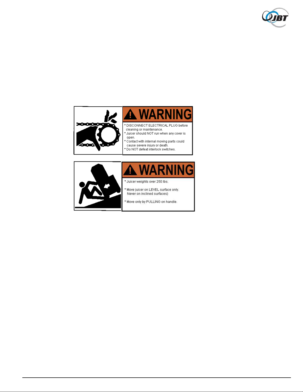
Safety Labels
The safety labels shown below appear on the Juicer. They provide essential instructions on how
to avoid possible hazards.
Please, for your safety: FOLLOW THOSE INSTRUCTIONS AT ALL TIMES.
Should the Juicer safety labels become damaged or unreadable, contact JBT Corporation for
replacement labels.
5 FNS-0004-060-EN December 2015 Rev B

Safety Instructions
Carefully review the following safety instructions.
Make them a habit when using the JBT Corporation Juicer.
1. If Juicer continues to run when any access cover is open, interlock switch is defective.
Turn Juicer off immediately. Call for service.
2. Prevent unauthorized access to Juicer by locking all covers with supplied key.
3. Prevent unauthorized operation of Juicer by placing electrical plug inside cart door.
4. NEVER attempt to make any safety device inoperative.
5. NEVER operate or perform maintenance or repair work on Juicer when taking any kind of
drug or sedative, when under the influence of alcohol, or when fatigued.
6. ALWAYS check adjustment of all nuts, bolts, and screws after installation, repair, or
periodic maintenance.
6 FNS-0004-060-EN December 2015 Rev B

TECHNICAL SPECIFICATIONS
Produce size: ………………………. No restrictions, up to pineapple
Hopper capacity: ............. .......…….. 12 - 15 Ib. depending on produce
Reservoir capac ity:.................…….. 5 qts.
Waste container capacity: .....……... 40 Ibs.
Speed:....................................……... 4 minutes for full hopper
(12 – 20 gallons/hour)
ELECTRICAL SPECIFIC ATIONS
115V 60Hz Single Phase 20 AMP Service
Dedicated line needed for Juicer.
Use 12 GA. wire minimum up to 100 ft. from main breaker panel, 10 GA. up to 200 ft.
SHIPPING SPECIFICATIONS
Height: 63-1/2"
Width: 24"
Depth: 29"
Weight: 350 Ibs.
7 FNS-0004-060-EN December 2015 Rev B

GENERAL INFORMATION
The Fresh'n Squeeze® Produce Plus Juicer is designed to provide years of dependable service
with significantly less downtime and maintenance. It uses a unique patented design to extract
every available amount of juice from the produce. This Juicer was designed to run high quality
fruits and vegetables mentioned on Page 10 only. To process citrus use our Fresh'n Squeeze
®
Multi-Fruit Juicer.
CERTIFICATIONS
UL - Approved
CUL - Approved (Canada)
NSF (National Sanitation Foundation) - Approved
8 FNS-0004-060-EN December 2015 Rev B

IMPORTANT GENERAL PRODUCE INFORMATION
Juicing fruits and vegetables requires that the highest quality standards be maintained. This is
also important for handling all produce and salad bar items. Failure to maintain these high
standards can lead to the growth of bacteria which can be harmful to your customers. By
following the procedures in this manual you can operate a safe and profitable juicing business.
CONDITION OF PRODUCE
Use only fresh, high quality produce from reliable vendors;
DO NOT use rotten, spotted, molded, or old fruit for juicing.
DO NOT use juicer as a cull disposal program for your produce.
DO NOT juice skin type produce (tomatoes) with splits in them. All of this will increase harmf ul
bacteria growth; such as, Salmonella, E. Coli, etc.
DO wash all produce with clean, fresh, drinking water only.
DO keep all produce cold (40°F). This will inhibit the growth of harmful bacteria.
DO keep in cooler until ready to juice.
JUICE HANDLING
Make sure that the containers and lids for filling are sanitized. Also, it is best to use the smallest
containers possible to prevent spoilage before consumption. Filled containers should be
refr igerat ed (34°- 40°F) immediately after filling; if put on ice, make sure entire container is
submerged. Limit shelf life for produce juice to one day in the store. Juice every day; do not
produce excessive juice inventory.
Juice must be consumed within three days.
9 FNS-0004-060-EN December 2015 Rev B

GENERAL PRODUCE INFORM ATION
NOTE: All fresh produce must be washed thoroughly and kept refrigerated before
juicing to maintain high juice quality standards. Culls must never be used.
Types of produce
Apples
All types; we recommend Washington Apples. Best if three different types are blended equally,
e.g. Red Delicious, Golden Delicious & Granny Smith.
Carrots
All types; but, California varieties are the best. Remove green portion. Some extra large
diameter (horse) carrots may have to be cut up.
Pineapple
Remove stem and peel.
Grapes
All types and blends. Remove stems to get a less bitter taste. Seedless grapes are preferred.
Celery
Remove top leafs and bottom core.
Tomatoes
Don't use low acid varieties and make sure there are no splits in skin.
Both conditions may allow fast, harmful, bacteria growth.
Pears, Nectarines, & Peaches
Remove all pits; may not give satisfactory juice due to thick consistency, but can be used for
blending with other fruits like apples and oranges.
Strawberries, Cranberries, Blueberries
All types.
Kiwi
Peeled only.
Rhubarb, Spinach
For blending with other juices only; do not drink unblended because of their high oxalic acid
content. Never use Rhubarb leaves due to high oxalic acid.
Melons
Caution: Never juice melons because of their high pH which encourages harmful
bacteria growth such as Salmonella.
Citrus
Not recommended due to the high peel oil content of the skin. Use the Fresh'n Squeeze™
Multi-Fruit Juicer for citrus.
10 FNS-0004-060-EN December 2015 Rev B
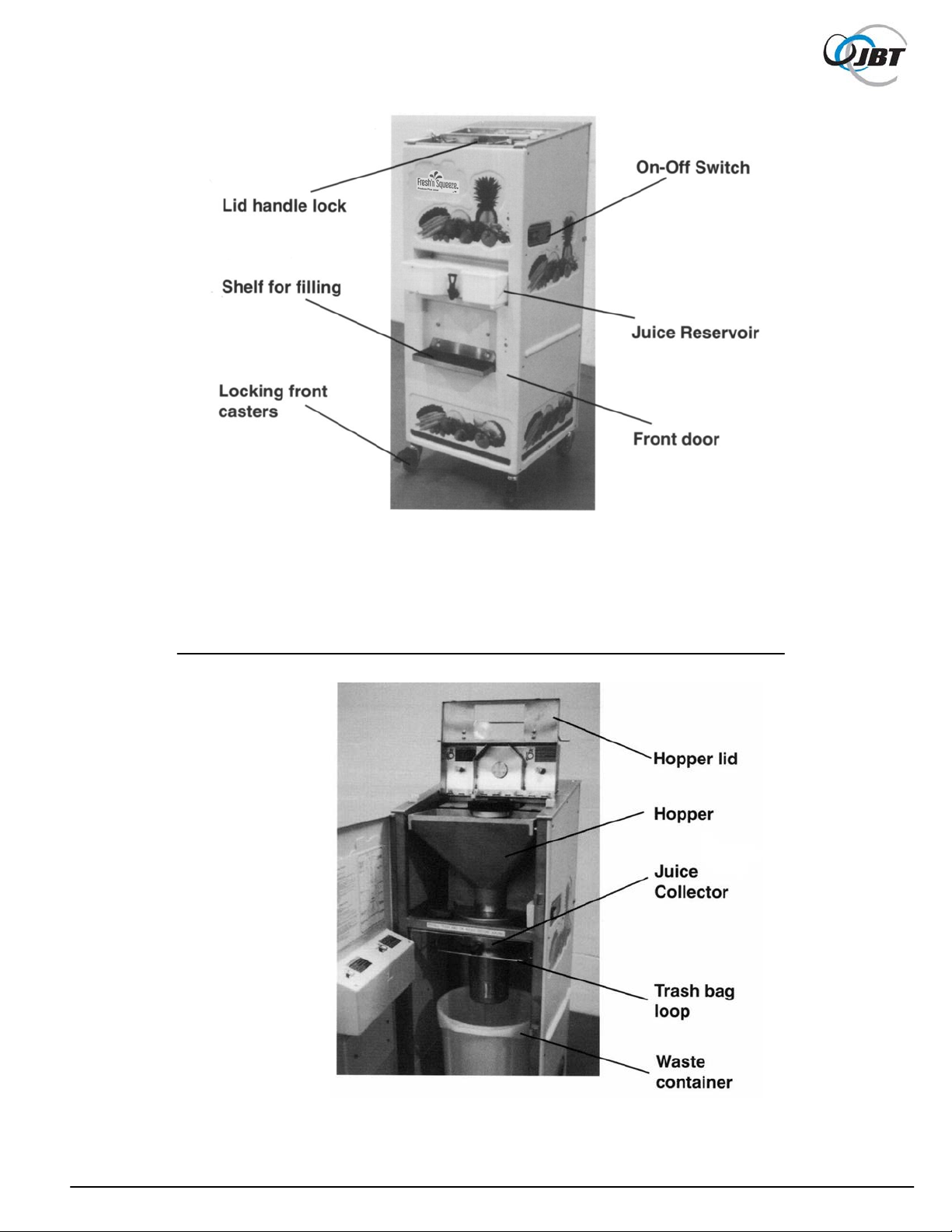
Figure 1a. Produce Plus Juicer
Figure 1b. Juicing Components Assembly
11 FNS-0004-060-EN December 2015 Rev B
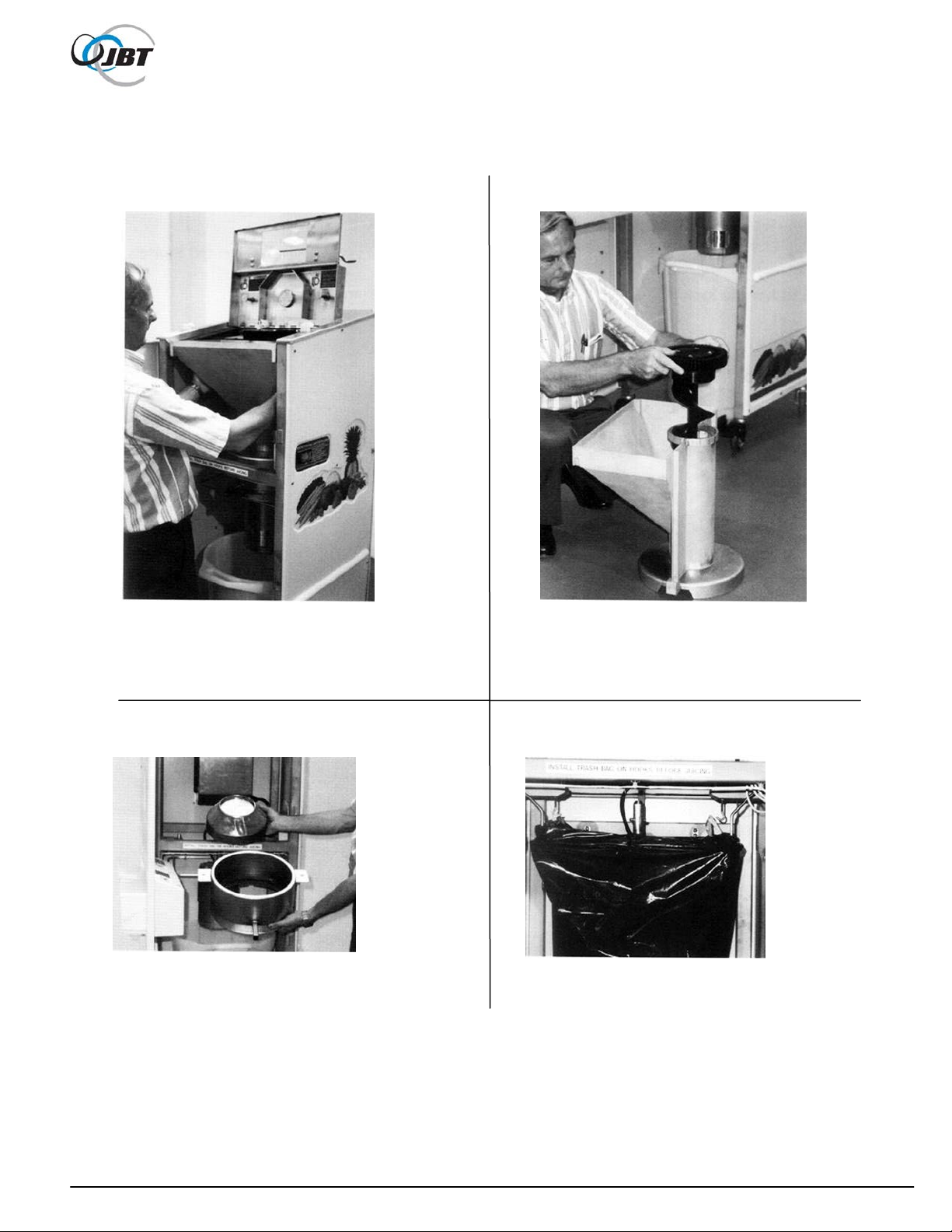
Figure 1c. Lifting out hopper Figure 1d. Lifting screw out of hopper
Figure 1e. Juice collector Figure 1f. Trash bag installed
12 FNS-0004-060-EN December 2015 Rev B

OPERATING INSTRUCTIONS
EQUIPMENT CHECK
Before plugging the JBT Corporation Juicer into an electrical outlet, the following steps
must be performed:
1. Make sure the juicer is clean per cleaning instructions.
2. Juice only in a clean, cool, dry location. The produce department sales floor is
typically the best location.
3. Locate the Juicer on a level surface.
This will prevent fruit feed problems.
4. Lock both front casters.
To lock, push down on caster with foot. To unlock, push again with foot.
5. Check waste container.
Open cart door to verify that waste container is in place. Make sure a plastic bag is
attached to the hooks above the waste container (recommend the "Hefty Cinch Sak
30 gallon capacity or equivalent, drawstring type).
6. Check juicing components.
Use key to unlock juicing components cover. Open cover and check that juicing
components are installed and securely fastened. See Figure 1b.
7. Close and lock all access covers.
There are two separate access covers: Hopper cover and juicing components door cover.
Never operate Juicer unless all covers are in place.
8. Make sure juice reservoir is firmly in place.
9. Make sure juice reservoir faucet is in the closed position.
10. Check the hopper for foreign objects.
Remove any foreign objects found in the hopper.
11. Make sure floor area around juicer is clean and free of obstructions and water.
®
",
W hen water is necessary, wear appropriate non-slip footwear.
13 FNS-0004-060-EN December 2015 Rev B

OPERATING INSTRUCTIONS
Juicing
Wash hands thoroughly before Juicing.
1. Bulk Feed
Unlock and open the hopper cover. Dump up to 15 Ibs. of produce into the hopper. Do not
force lid closed; remove some produce, if hopper is too full.
2. Turn on Juicer
Push the "ON-OFF" button to "ON" position.
3. Automatic Shut-Off
Juicer may shut off with produce in hopper due to high juice level in reservoir. There is a
high level shut-off to prevent the overflow of juice.
4. Turn-off Juicer
Push the "ON-OFF" switch to the "OFF" position.
5. Stir Juice
Use stirrer handle to stir juice in reservoir before filling containers. Fill containers
immediately. DO NOT let juice stand in the reservoir.
6. Discard the first 1 - 2 ounces of juice produced.
This will ensure that any prior contamination or residue is eliminated.
7. Taste each batch of juice for quality before filling containers.
Discard poor tasting product.
8. Fill Containers
Place sterile container under juice reservoir faucet. Open faucet by depressing handle until
container is full. Fill shelf has two adjustments for short and tall containers. Cap juice
immediately and refrigerate at 34°-40°F. All bottles must be coded with three days shelf life
maximum. (See Juice Handling Section)
14 FNS-0004-060-EN December 2015 Rev B

OPERATING INSTRUCTIONS
9. Juicing Different Produce
It is not necessary to fully clean Juicer if immediately switching to another type of juice. Fill a
one gallon container with drinking water. Open hopper and use 1/2 gallon water to rinse leftover product residue. Close hopper and turn on juicer. Pour the remaining 1/2 gallon water
into funnel type hole on top of hopper lid. Remove water from reservoir and rinse throughly.
Proceed to juice the next type of produce.
Water being poured into hole in hopper
10. Clean Juicer
If finished juicing, clean Juicer immediately.
(See next page for cleaning instructions.)
15 FNS-0004-060-EN December 2015 Rev B

CLEANING INSTRUCTIONS
Thorough cleaning of all Juicer components is a necessity.
Do not take any short-cuts in cleaning or sanitizing.
ALWAYS follow cleaning and maintenance schedules in this manual to prevent
equipment damage.
Clean Juicer immediately after juicing. Use a clean soft towel or sponge to wipe equipment
parts. Never use abrasive pads such as steel wool, etc.
The recommended cleaner is JBT Corporation brand CorKlean. CorKlean is a low-foaming
alkaline equipment cleaner. It is safe on aluminum, 100% water soluble and free rinsing.
CorKlean has been especially formulated for cleaning food processing equipment and is USDA
accepted. Follow instructions on cleaner label for dilution.
1. Turn-off Juicer.
2. DISCONNECT ELECTRICAL PLUG.
3. Pull Juicer to clean-up area, if one is available.
16 FNS-0004-060-EN December 2015 Rev B

CLEANING INSTRUCTIONS
4. a. With both hands lift hopper up and out, with plastic feed screw in it.
b. Remove juice collector pan.
CAUTION: TEETH ON GRATER ARE SHARP.
c. Remove screen assembly; remove large pieces of product from inside of screen and
place into waste container.
d. Remove trash bag from hooks; then, remove waste container.
e. Remove juice reservoir and fill shelf.
5. If possible, hose down inside and outside of Juicer with hot drinking water; if not, with waste
container in place, sponge or spray juicing area with cleaning solution. Rinse with hot
drinking water. Be sure to clean stainless steel drive gear. Wipe dry.
6. With a hose or spray nozzle, rinse off all juicing components with clean hot water.
A hard spray on screen assembly will remove all stuck product. Make sure to remove
plastic feed screw from hopper.
7. Prepare a cleaning solution of clean hot water and CorKlean in a sink or large container. .
Follow instructions on cleaner label for dilution..
8. Use brush provided to scrub all juicing components in the solution; (never use a wire brush).
Pay particular attention to cleaning the screen and grater plate. Be careful, the grater teeth
are sharp. If stains are not easily removed, allow juicing components to soak for ten
minutes or longer.
9. Rinse all juicing components with clean hot water; then, thoroughly rinse with sanitizer
solution per manufacturer's mixing directions and safety precautions. Allow to air dry.
10. Re-assemble Juicer per assembly instructions.
17 FNS-0004-060-EN December 2015 Rev B

CLEANING INSTRUCTIONS
11. Install trash bag onto loop and hooks.
12. Make sure waste container is in place.
13. Re-install reservoir and fill shelf with grate.
14. Air dry by turning Juicer on for a minute or two.
15. If reservoir or covers become stained, or mold appears on inside of covers, clean with
appropriate disinfectant cleaner. Follow manufacturer’s directions and safety precautions.
Rinse thoroughly with water.
16. Clean grease marks from covers. Follow manufacturer’s directions and safety precautions.
18 FNS-0004-060-EN December 2015 Rev B

19 FNS-0004-060-EN December 2015 Rev B

MAINTENANCE
Before performing any maintenance,
DISCONNECT ELECTRICAL PLUG.
Juicer requires no lubrication.
DO NOT LUBRICATE ANY BEARING, ROD END, OR SHAFT.
After every juice run:
1. Check screen assembly for damage, or missing mounting screws. Replace if
necessary.
a. Screen removal:
With a flat type screwdriver, remove (4) mounting screws as shown in photo.
CAUTION: Teeth on grater ar e sha rp
Removing mounti ng screws
20 FNS-0004-060-EN December 2015 Rev B

MAINTENANCE
b. Screen Installation:
Reassemble, making sure screws are securely tightened. Reinstall in Juicer. Jog
2. Check grater on screen assembly for missing teeth. If any are missing, replace
3. Check grater on screen assembly for worn teeth.
If out er rows of teeth are almost completely worn down, replace grater.
4. Check large plastic gear on top of feed screw for damage.
5. Check large plastic feed screw for damage.
6. Check for damaged or missing feed screw tip. Replace if less than 1/32" thick. Remove
Juicer to make sure there is no interference.
immediately. DO NOT use.
a. If burred, use knife or file to dress-up corners and edges.
b. If teeth are missing, replace gear.
c. Replace by removing four socket head screws.
DO NOT over-tighten when reassembling.
a. If burred, use knife or file to dress-up.
by turning tip to the left.
21 FNS-0004-060-EN December 2015 Rev B

MAINTENANCE
7. Check motor drive pin. Make sure it is in place and centered in shaft.
8. Check for loose or missing nuts and bolts.
a. Tighten or replace nuts and bolts as necessary.
ALWAYS use JBT Corporation recommended spare parts.
22 FNS-0004-060-EN December 2015 Rev B

TROUBLE SHOOTING
CAUTION: NEVER reach into moving parts to clear a jam,
no matter how simple it seems.
Juicer will not start.
1. Extractor is not plugged into electrical outlet.
2. Building circuit breaker has tripped.
3. All covers are not completely closed including cart and back (cover).
4. High level in reservoir has shut juicer off. Shut off level is approx. 3/4 full.
5. Equipment is jammed.
Call for service.
6. "ON-OFF" switch is defective.
Call for service.
Juicer will not start; but, buzzing sound comes from "ON-OFF" switch.
1. Overloaded circuit.
Machine needs to be on separate (its own) electrical circuit.
2. One or more covers partially closed causing intermittent contact of interlock switch.
3. Low voltage to machine.
Use 110 volts minimum.
Juicer starts, but shuts off.
1. Building circuit breaker is not rated for 20 Amps.
2. Extension cord or wiring is too long.
Eliminate extension cord or use heavier gauge wire.
(See "Specifications")
3. All covers are not completely closed.
Close any open covers.
4. One or more covers has a defective interlock switch.
Turn off Extractor. Call for service.
5. Juice in reservoir has reached max. level - approx. 3/4 full.
Juicer runs with covers open or off.
Turn off Juicer. Call for service.
23 FNS-0004-060-EN December 2015 Rev B

Produce Bridging in Hopper
1. Hopper has dirt or wax built-up.
Clean Hopper.
2. Extremely large carrots.
Break into two pieces before loading into hopper.
Vibration Noise
1. Screen assembly is off balance due to large amount of matted/dry product (especially if
running celery or pineapple) on side of screen.
Remove screen assembly and remove dry product. Reassemble.
Scraping Noise
1. Juicing components not assembled properly and/or product on mounting surfaces.
Check, clean, and re-assemble.
2. Foreign object on grater (seed, rock, etc.)
Remove Hopper and remove object.
Large Pieces of Product in Juice
1. Juicing components not assembled properly
Clean and re-assemble.
2. Damaged screen assembly
Check for holes and replace if necessary.
24 FNS-0004-060-EN December 2015 Rev B

TROUBLESHOOTING
Waste Product on Floor
1. Trash bag not installed or not installed properly. See photo on page 12.
Juice on Floor
1. High level shut off in reservoir not adjusted properly.
Adjust so juicer shuts off before juice level gets to hole in back of reservoir - approx . 3/4 full.
Hopper Cover Will Not Stay in up Position
1. Call For Service.
25 FNS-0004-060-EN December 2015 Rev B

Item
Qty
Part Number
Description
1
1
060-05004-F
Cover Parts Details See Pag es 28 through 30
2
1
060-05067-01
Feed Screw Assembly Details See Page 31
3
1
060-05051-B
Hold Down
4
2
004-352-280
Screw, Cap Hex, 1/4-28 x 3/4" Lg, S.S.
5
2
060-05081-B
Hopper Lid Retainer
6
1
060-05105-C
Hopper Lid
7
4
004-501-060
Screw, Cap Hex Head, S/L,1/4-20 x 1" Lg, S.S.
8
1
007-055-526
Clevis
9
1
009-715-098
Gas Spring
10
2
060-05029-B
Hold Down, Hopper Handle
11
1
060-05130
Hopper, S.S. (replaces 06 0 -05013)
12
1
060-05042-C
Juice Collector
13
4
004-385-009
Screw, Mach, Flat Head, #6-32 X 1/2" Lg,S.S.
14
1
060-05088-C
Grater Disc & Hub Assembly – Includes Item 14a
14a
1
060-05087-C
Grater Disc only
15
1
060-05037-C
Screen
16
1
060-05058-B
Key Ring & Key
17
1
060-05028-C
Handle, Hopper Lid
18
6
004-401-022
Screw, Mach., Truss Head, #10-24 x 3/ 8" Lg, S.S.
19
1
060-05055-B
View Window, Hopper
20
4
004-816-060
Washer, Plain, 1/4"
21
1
060-00120-B
Sign, Warning, Covers
22
1
060-00176-B
Sign, Warning, Spanish
23
1
060-00082-B
Label, Hopper English (Not Shown)
25
2
004-111-035
Nut Hex,1/4-28, S.S.
26
1
009-080-327
Brush, Veg. (Not Shown)
27
1
009-080-328
Brush, Valve (Not Shown)
28
1
009-425-020
Spare Key (Not Shown)
29
1
060-05080-B
Label, Cord
30
1
004-111-040
Nut Hex, 5/16-18, S.S.
31
1
060-05083-C
Waste Chute
32
3
004-352-312
Screw, Cap Hex, 5/16-18 x 5/8" Lg, S.S.
33
4
004-806-050
Lock Washer, 1/4"
34
1
060-02087-B
Safety Key
35
2
004-392-174
Screw, Mach., Pan Head, #8-32 x 1/2" Lg
36
2
060-02059-B
Button Nut, #8-32
37
1
006-200-481
Safety Key, Angled
38
2
004-401-022
Screw, Mach., Truss Head, #10-24 x 3/ 8" Lg, S.S.
39
1
060-00082-B
Label, Hopper Spanish (Not Shown)
After 2013:
4
2
060-05137
Threaded Rod, Hopper Lid
10
1
060-05136
Handle, Hopper Lide
25
2
004-116015
Nut Hex,1/4-20, S.S.
Juicer Final Assembly 060-05000-R
26 FNS-0004-060-EN December 2015 Rev B

27 FNS-0004-060-EN December 2015 Rev B

Item
Qty
Part Number
Description
1
1
060-05002-F
Drive Assembly Details See Pages 32 through 33
2
1
060-05027-C
Float Frame
3
1
009-210-013
Float
4
1
060-00140-B
Magnet Holder
5
1
006-210-291
Magnet
6
1
060-05026-C
Reservoir Stirrer
7
4
060-05021-B
Pin, Shelf Hanger
8
1
060-05019-C
Shelf, Fill Container
9
1
060-05020-C
Grate, Fill Container
10
1
060-05063-B
Faucet
11
1
060-05073-B
Jam Nut
12
1
009-210-018
Washer
13
1
060-05006-C
Lid, Juice Reservoir
14
1
060-05005-D
Reservoir, Juice
15
1
060-05011-F
Door
16
32
004-401-032
Screw, Mach., Truss Head, #10-24 x 1" Lg, S.S.
17
1
060-05043-B
Access Plate, Back Cover
18
1
004-156-041
Nut, Hex, Self-Locking, #10-24, S.S.
19
1
060-05008-C
Cover, Back
20
1
060-05056-D
Cover, Top
21
1
060-05010-C
Cover, Right Side
22
1
060-05009-C
Cover, Left Side
23
1
060-00148-B
Label, Trash Bag
24
4
004-156-049
Nut, Hex, Self-Locking, 1/4-20, S.S.
25
1
009-092-020
Waste Container
26
1
060-05057-C
Handle
27
2
060-05030-B
Lid Handle Lock
28
4
004-401-033
Screw, Mach., Truss Head, #10-24 x 1-1/4" Lg, S.S.
29
6
004-816-052
Washer, Plain #10, S.S.
30
13
004-401-022
Screw, Mach., Truss Head, #10-24 x 3/ 8" Lg, S.S.
31
1
060-00122-B
Label, Moving Juicer
32
1
015-03935-B
Name Plate, Domestic
32
1
015-03938-B
Name Plate, Export
33
8
004-265-016
Pop Rivet, 1/8 x 1/4
34
1
015-03934-B
Patent Plate
35
1
060-05068-C
Assembly Decal
36
1
060-05069-C
Cleaning Decal
37
1
060-05076-B
Mounting Plate for Decals
38
1
060-05072-B
Label, Wash Produce
39
2
009-395-017
Plastic Knob
40
2
004-397-142
Screw, Mach., Round Head, #10-32 x 1/2" Lg, S.S.
41
2
004-816-052
Washer, Plain, #10
42
1
060-00175-B
Label, Moving Juicer, Spa nish
Cover Parts 060-05004-F
28 FNS-0004-060-EN December 2015 Rev B

29 FNS-0004-060-EN December 2015 Rev B

30 FNS-0004-060-EN December 2015 Rev B

Item
Qty
Part Number
Description
1
1
060-05045-D
Feed Screw
2
1
060-05050-B
Tip, Feed Screw
3
1
060-05031-B
Gear, Feed Screw
4
4
004-356-117
Screw, Cap, Socket, 3/8-16 x 2" Lg, S.S.
Feed Screw Assembly 060-05067-01
31 FNS-0004-060-EN December 2015 Rev B

Item
Qty
Part Number
Description
1
1
060-05003-F
Frame Weldment
2
2
009-080-530
Caster
3
2
009-080-531
Caster w/ Brake
4
1
060-05099
110V/60Hz Field Replac ement Motor
5
1
060-05007-C
Motor Clamp
6
3
004-352-398
Screw, Cap Hex, 3/8-16 x 1-1/4" Lg, S.S.
7
3
004-111-048
Nut Hex, 3/8-16, S.S.
8
1
060-05079-B
Pin, Motor Drive
9
2
060-05077-B
Bag Hook
10
4
004-111-022
Nut Hex, #10-24, S.S.
11
2
060-05048-B
Pin- Hopper Lower
12
1
060-05066-D
Electrical Assembly, 110 Volt, 60 Hz
Details See Pages 34 through 36
13
6
004-401-022
Screw, Mach, Truss Head, #10-24 x 3/8 Phillips, S.S.
14
1
060-05047-D
Bag Loop
15
2
060-05049-B
Pin, Hopper Upper
16
2
004-506-089
Screw Cap Socket, 1/4-20 x 5/8" Lg, Nylok, S.S.
17
1
060-05052-B
Waste Container Hanger
18
2
060-05078-B
Cleaning Tool Hook
21
1
060-05108-B
Slinger, Motor Shaft
22
3
004-806-070
Washer, Lock, 3/8" (Motor-3 Required)
220V/50Hz Motors:
12
1
060-05066-D
Electrical Assembly, 220 Volt, 50 Hz
Details See Pages 40 through 42
20
1
060-05102
220V/50Hz Field Replac ement Motor
Tools for Motor Replace ment:
1 060-05090
Motor Mounting Fixture
1 060-05142
Grater, Gap Tool, Gage
1 060-05143
Hub Grater Drive Tool
1 060-05144
Hub/Disk Assembly
1 060-05145
Hopper Spacer, Gage
Drive Assembly 060-05002-F
32 FNS-0004-060-EN December 2015 Rev B

33 FNS-0004-060-EN December 2015 Rev B

Item
Qty
Part Number
Description
2 5
009-097-003
Cable Tie
4
1
060-05060-C
Enclosure, Start Switch Assembly
5
2
004-401-022
Screw Mach., Truss, #10-24 x 3/8" Lg, Phillips, S.S.
6
1
060-05074-B
Cord Type SJO 4 Cond 16 G A
7
1
006-270-141
Cable Mount Small
8
1
060-05065-C
Electrical & Gearbox Sub-Assembly
9
3
006-220-014
Terminal, # 10 Ring End 10-12 G A.
10
4
004-156-063
Nut Hex, 5/16-18 Self-Locking, S.S.
11
1
006-210-290
Proximity Switch (NC)
12
1
006-080-071
Power Cord #12/3 x 10'-0" Lg
13
4
004-111-022
Nut, Hex, #10-24, S.S.
14
4
004-816-070
Washer Plain, 5/16, S.S.
15
2
006-221-082
1/4 Spade Term 16 GA
16
1
006-221-084
1/8 Spade-Fem-20 GA
17
1
004-397-129
Screw Mach., Round Hea d, # 10 -24 x 1/4" Lg
18
4
009-654-002
Cable Retainer
19
2
006-200-482
Switch, Interlock, Sch mersal #AZ15
20
1
007-143-370
Fitting, Strain Relief, 90º
21
1
007-143-395
Fitting, Strain Relief, Straight
22
1
006-080-073
Cord, 14/2 x 42"
23
1
006-080-073
Cord, 14/2 x 27"
24
2
004-401-026
Screw, Mach., Truss Head, #10-24 x 5/8" Lg, S.S.
25
4
004-816-052
Washer, Plain, #10
26
1
004-401-032
Screw, Mach., Truss Head, #10-24 x 1" Lg, S.S.
27
2
004-440-011
Screw Type “F”, #6-32 x 1/2" Lg, S.S.
28
1
007-143-474
Fitting, Strain Relief, 90°
29
1
007-143-396
Fitting, Straight Strain Relief
Electrical Diagram & Assembly, 110 Volt 060-05066-D
34 FNS-0004-060-EN December 2015 Rev B

35 FNS-0004-060-EN December 2015 Rev B

36 FNS-0004-060-EN December 2015 Rev B

Item
Qty
Part Number
Description
1
1
060-05059-C
Enclosure, Electrical
2
1
006-060-078
Strain Relief Fit t in g
3
1
006-060-077
Strain Relief Fit t in g
4
1
006-221-079
Terminal Block, Phoenix #G 5/6
5
1
006-200-474
Switch, On/Off, Weber #AHWTHD15Z4
6
1
009-235-073
Switch Gasket
7
2
004-440-001
Screw, Type “F”, #4-40 x 3/4" Lg, S.S.
8
2
004-440-011
Screw, Type “F”, #6-32 x 1/2" Lg, S.S.
9
2
060-05064-B
Spacer, Terminal Bloc k
10
1
007-486-118
Sealing Ring, Hubbell #205-09-001
11
1
007-146-010
Nut, Tru-Seal, 1/2 NPT
12
1
060-00096-03
Wire, White, 20 GA x 5"
13
1
006-221-084
1/8 Spade Female 20 GA
14
A/R
009-455-002
Marker Pins, Phoenix #B NB:1-6
15
2
004-440-010
Screw, Type “F”, #4-40 x 3/8" Lg, S.S.
16
1
006-221-082
1/4 Spade Term 16 GA
17
1
006-221-083
1/4 Spade Term 12 GA
18
1
006-260-068
Wire, Black, 16 GA x 10" Lg
Enclosure, Start Swit c h Assembly 060-05060C
37 FNS-0004-060-EN December 2015 Rev B

Item
Qty
Part Number
Description
1
1
060-05033-F
Electrical Box
2
1
060-05062-C
Panel Assembly, Electrical
3
1
005-617-149
Gearmotor
4
1
060-05032-B
Gear, Stainless Steel
5
1
005-576-223
Key, Sq. 3/16 x 1" Lg, S.S.
6
2
004-541-111
Screw, Set, Self-Locking, 5/16-18 x 3/4" Lg, S.S.
7
1
060-05070-B
Drain Vent
8
1
006-270-194
Connector, Cord, Hubbell #NHC-1023-CRN
9
2
006-060-077
Connector, Cord, 1/2 NPT x 1/ 2 Cord, T&B #2673
10
6
004-401-022
Screw, Mach., Truss Head, #10-24 x 3/ 8" Lg, S.S.
11
3
007-486-118
Sealing Ring
12
3
007-146-010
Nut, Tru-Seal, 1/2 NPT
13
4
004-352-280
Screw, Cap Hex, 1/4-28 x 3/4" Lg, S.S.
Electrical & Gearbox Sub-Assembly 060-05065-C
38 FNS-0004-060-EN December 2015 Rev B

Item
Qty
Part Number
Description
1 1
060-05061-C
Panel, Electrical
2 or 11
1
006-035-023
Capacitor, 340-408 MFD, 110V (Supplied with Moto r)
3 or 12
1
006-035-024
Capacitor, 25 MFD, 110V (Supplied with Motor)
4
1
006-035-025
Capacitor, 15 MFD, 60 or 50 Hz (Supplied with Gearmotor)
5
1
006-221-080
Terminal Block, Phoenix #G 5/12
6
2
004-440-001
Screw, Type “F”, #4-40 x 3/4" Lg, S.S.
7
2
009-723-039
Clamp, Capicator, Richc o #UM S-32-45
8
3
004-397-077
Screw Mach., Round Head, # 8-32 x 1/2" Lg
9
A/R
009-455-003
Marker Pins, Phoenix #B NB:1-12
10
2
006-221-082
1/4 Spade Term 16 GA
11
1
006-035-026
Capacitor, 460-552 MFD, 220V (Supplied with Motor)
12
1
006-035-029
Capacitor, 30 MFD, 220V
Items 2 & 3 are for 110 Volt Motors, It ems 11 & 1 2 are for 220 Volt Motors
Electrical Panel Assembly 060-05062C
39 FNS-0004-060-EN December 2015 Rev B

Item
Qty
Part Number
Description
2
5
009-097-003
Cable Tie
3
2
004-440-011
Screw Type “F”, #6-32 x 1/2" Lg, S.S.
4
1
060-05060-C
Enclosure, Start Switch Assembly
5
2
004-401-022
Screw Mach., Truss, #10-24 x 3/8" Lg, Phillips, S.S.
6
1
060-05104-B
Cord, 4 Cond 16 GA
7
1
006-270-141
Cable Mount Small
8
1
060-05065-C
Electrical & Gearbox Sub-Assembly
9
3
006-220-014
Terminal, # 10 Ring End 10-12 G A.
10
4
004-156-063
Nut Hex, 5/16-18 Self-Locking, S.S.
11
1
006-210-290
Proximity Switch (NC)
12
1
006-080-072
Power Cord #14/3 x 10'-0" Lg
13
4
004-111-022
Nut Hex, #10-24, S.S.
14
4
004-816-070
Washer Plain, 5/16, S.S.
15
2
006-221-082
1/4 Spade Term 16 GA
16
1
006-221-084
1/8 Spade-Fem-20 GA
17
1
004-397-129
Screw Mach., Round Head, # 10-24 x 1/4" Lg
18
4
009-654-002
Cable Retainer
19
1
060-05092-C
Enclosure, Transfor mer
20
1
060-05091-C
Plate, Mounting, Transformer
21
1
006-240-030
Transformer, Signal #M4L-2-10
22
2
006-270-194
Connector, Cord, Hubbell #NHC-1023-CRN
23
2
007-486-118
Sealing Ring
24
2
007-146-010
Nut, Tru-Seal, 1/2 NPT
25
2
060-05070-B
Drain Vent
26
4
004-401-022
Screw, Mach., Truss Head, #10-24 x 3/8" Lg, S.S.
27
4
004-605-007
Stand-Off, Male/Female #10-32 Thread, S.S.
28
4
004-156-043
Nut Hex, #10-32, Self-Locking, S.S.
29
2
004-392-172
Screw, Hex, Socket Head, 1/4-28 x 3/4" Lg, S.S.
30
2
004-816-063
Washer, Plain, 1/4", S.S.
31
3
006-220-004
Terminal, # 10 Ring End 16-14 G A
32
1
004-397-129
Screw, Mach., Round Head, #10-24 x 1/4" Lg, S.S.
33
1
006-080-079
Cord #12/3 x 28" Lg
34
1
Plug
Determined by Machines Destintation
35
1
060-05094-B
Grommet
36
2
006-200-482
Switch, Interlock, Sch mersal #AZ15
37
1
007-143-370
Fitting, Strain Relief, 90º
38
1
007-143-395
Fitting, Strain Relief, Straight
39
1
006-080-073
Cord, 14/2 x 42"
40
1
006-080-073
Cord, 14/2 x 27"
41
2
004-401-026
Screw, Mach., Truss Head, #10-24 x 5/8" Lg, S.S.
42
4
004-816-052
Washer, Plain, #10
43
1
004-401-032
Screw, Mach., Truss Head, #10-24 x 1" Lg, S.S.
44
1
007-143-474
Fitting, Strain Relief, 90°
45
1
007-143-396
Fitting, Straight Strain Relief
Electrical Diagram & Assembly, 220 Volt 060-05093-D
40 FNS-0004-060-EN December 2015 Rev B

41 FNS-0004-060-EN December 2015 Rev B

220 VOLT MACHINE
42 FNS-0004-060-EN December 2015 Rev B
 Loading...