


2nd Generation
Multi-Fruit Juicer
Service Manual
June 2019

nd
2
Generation
Multi-Fruit Juicer
Service Manual
Copyright © John Bean Technologies Corporation 2019
JBT Corporation
400 Fairway Avenue
Lakeland, FL 33801
(863) 683-5411
Manual No. FNS-0014-060-EN
2 FNS-0014-060-EN June 2019 Rev A

Table of Contents
Important Safety Information ······································ 4
Specifications ··························································· 6
General Information ·················································· 7
Juicer Screen Descriptions ······································· 9
Maintenance ····························································· 22
Troubleshooting ······················································ 28
Rebuilding ······························································· 31
Illustrated Parts List ················································· 45
Electrical Drawings and Procedures ···························· 75
3 FNS-0014-060-EN June 2019 Rev A

North America
Fax: +1 863 680 3672
Europe
South Africa
Fax: +27 21 982 1136
www.jbtcorporation.com
Brazil
Latin America
Asia / Pacific
Fax: +86 21 6341 0708
FNS-0014-060
A
06/14/19
Initial release
Important Safety Information
You can help prevent personal injury and/or property damage.
Please read this manual carefully before operating the Multi-Fruit Juicer.
DO NOT attempt any operation until you understand exactly how the machine functions.
If uncertainty remains after studying this manual, please contact John Bean Technologies
Corporation.
We're here to help. With proper handling, the JBT Multi-Fruit Juicer will provide safe, efficient
and convenient service for years to come.
Revision History
Manual
Code
Rev. Date Change History
JBT Corporation
400 Fairway Ave
Lakeland, FL 33801
USA
Phone: +1 863 683 5411
JBT Máquinas e Equipamentos Industriais Ltda.
Av. Eng. Camilo Dinucci 4605
14808-900 Araraquara
São Paulo Brazil
Phone: +55 16 3301 2000
Fax: +55 16 3332 0565
JBT Corporation, S.L.
Julián Camarillo 26, 4º
28037 Madrid Spain
Phone: +34 91 304 00 45
Fax: +34 91 327 50 03
JBT Corporation
Carr. Mty-Saltillo Km 7—Bodega 4
Colonia Las Mitras
Santa Catarina, NL
Mexico 66350
Phone: +52 81 81 23 70 55
Fax: +52 81 81 23 70 54
JBT (Pty) Ltd.
Koper Street
Brackenfell
Cape Town, South Africa 7560
Phone: +27 21 982 1130
JBT (Shanghai) Co. Ltd.
Room 3002-3003
Haitong Security Building
No. 689 Guangdong Road
Shanghai 200001,
China
Phone: +86 21 6341 1616
4 FNS-0014-060-EN June 2019 Rev A

Safety Labels
The safety labels shown below appear on the Juice Extractor. Safety labels provide essential
instructions on how to avoid possible hazards.
Please, for your safety: FOLLOW THOSE INSTRUCTIONS AT ALL TIMES.
Should the Juicer safety labels become damaged or unreadable, contact JBT Corporation for
replacement labels.
Safety Instructions
Carefully review the following safety instructions.
Make them a habit when using the JBT Corporation Multi-Fruit Juicer.
1. If Juicer continues to run when any access cover is open, the interlock switch is defective.
Turn Juicer off immediately. Call for service.
2. Prevent unauthorized access to Juicer by locking all covers with supplied key.
3. Prevent unauthorized operation of Juicer by placing electrical plug inside cart door.
4. NEVER attempt to make any safety device inoperative.
5. NEVER operate or perform maintenance or repair work on the Juicer when taking any kind of
drug or sedative, when under the influence of alcohol, or when fatigued.
6. ALWAYS check adjustment of all nuts, bolts, and screws after installation, repair, or periodic
maintenance.
7. NEVER attempt to operate or transport machine if the caster wheels are damaged, do not roll
freely, or if front and rear brakes do not lock.
5 FNS-0014-060-EN June 2019 Rev A

Specifications
Technical Specifications
Fruit size: 2 1/2" to 3 3/4" diameter (6.5 cm to 9.5 cm)
Oranges — FL: ·································· 125 to 50 count
Oranges — CA: ································· 138 to 48 count
Grapefruit — FL: ································ 56 to 48 count
Hopper capacity: ································ 80 Ib. (2 cartons) (36 kg)
Reservoir capacity: ···························· 3.5 gal. (1 carton) (13.2 liters)
Waste container capacity: ···················· 40 Ib. of peel (2 cartons) (18 kg)
Three Speeds:·································· 25 fruit/minute, 29 fruit/minute, 33 fruit/minute
Electrical Specifications
115V, 60 Hz Single Phase 15 AMP Service on a dedicated circuit
10 GA. wire — up to 200 ft. from main breaker panel
or
220 VAC, 50 Hz / 60Hz Single Phase 16 AMP Service
10 GA. wire — up to 200 ft. from main breaker panel
Shipping Specifications
Height: 65.4" (166 cm)
Width: 26" (65 cm)
Depth: 35" (89 cm)
Weight: 711 Ibs (323 kg)
Patents
U.S. Patents - #4905586 and #4922814
and Patents Pending
6 FNS-0014-060-EN June 2019 Rev A

General Information
The JBT Corporation Juicer is designed to provide years of dependable service. It uses a
unique patented design to extract every available amount of juice from the fruit with the
least amount of peel oil. The peel is completely separated from the juice and juice sacs
before being compressed and strained.
The machine will juice all types of citrus — oranges, grapefruit, lemons, limes, tangerines,
etc. — without changing or adjusting parts. In fact, different varieties and sizes of fruit can
be juiced to create various fruit juice blends.
Clean-up is simple, requiring disassembly of only five parts. All waste material — peel,
membranes, and seeds — is collected in a disposable garbage bag for easy removal and
disposal.
The Juice Extractor is solidly built using heavy duty components in all assemblies, including
the drive. It is simple to operate and uses a minimal number of parts.
ALWAYS follow cleaning and maintenance schedules in this manual to prevent equipment
damage and maintain juicer performance.
Figure 1. 2nd Generation Multi-Fruit Juicer
7 FNS-0014-060-EN June 2019 Rev A

Figure 2. Juicing Components Assembly
8 FNS-0014-060-EN June 2019 Rev A

B
C
B C D A D
Juicer Screen Descriptions
Standard Start Screen
Self-Service Start Screen
A. Start Button – Starts juicing
B. Go to Settings – Options to change the juicing speed and the animation shown while juicing.
C. Go to Status – View various information about the unit.
D. Go to Service – Various settings for the juicer (service personnel only).
Access requires a password which is simply “1”.
9 FNS-0014-060-EN June 2019 Rev A

Service 1
A B C D E
F
A. Total Cycles – Indicates the total number of cycles the juicer has run. This is value can be
changed by clicking on it. This is only meant for cases where electrical boxes are being
replaced so that the total juicers cycles will not be lost.
B. Cycles since last service – Indicates how many cycles have run since the last time the juicer
was serviced.
C. Reset Service Date – The button to the right of this will reset the service date shown below as
well as on the status screen.
D. Last Service Date – This shows what the date of the last service was for the juicer. The format
for this date is: Month Day Year.
E. Support Phone Number – Phone number for the service company for the juicer. To change
the number, simply click on the number itself and a keyboard will appear. If desired, dashes and
symbols can be added by clicking the down arrow on the top left twice, the dash is next to the
enter button. Click the up arrow in the top left to return to the numbers. This phone number
appears for general users on the Status page and Safety Fault screen.
F. Constant speed setting – Setting for testing the juicer at a constant speed either slower or
faster than normal operation. To use this feature the juicer must be on the normal speed setting
(top option on the settings screen). Once on this setting, the juicer will operate at whatever
frequency is specified here between 15 and 90 Hz. For example, with this feature the juicer can
be set to run at 15 Hz to see if parts are interfering with each other. This is programed to
default to 60 Hz whenever the juicer is powered off so as not to affect customer operation.
10 FNS-0014-060-EN June 2019 Rev A

A
B D E C F
Service 2
A. Clock – To change the date and clock, click on the numbers. Date and time format are show
above. Time is based on 24 hour format
B. Machine number – Click the numbers to enter the juicer's serial number. The serial number
can be found on the plate on the back of the juicer towards the bottom. The number entered
here is also displayed on the status page for general users to view.
C. Store number – Optional feature for entering an identification number for the facility where the
juicer is located. Currently not used elsewhere in the software.
D. Safety Check – Only viable on certain juicers. This provides a warning (shown later) if a safety
sensor has failed or is unplugged.
a. Turning this on for juicers that do not support this feature (certain juicers with serial
number starting with 83 and 93) will cause the safety circuit fault to always be on,
regardless if the safeties work or not. Refer to Safety Circuit Fault screen to turn off.
E. Tap – Changes how the juicer is operated. When activated, the juicer will run when the tap
handle is depressed, there is no longer a start button. Be aware that this feature requires
several physical alterations to the juicer including removal of the tank, a new front door, tap
housing, new safety sensor assembly, and modified juice manifold.
F. Language – Selection page to determine what language all the text is displayed in, available
languages are shown next.
11 FNS-0014-060-EN June 2019 Rev A

Languages
Selection for the language of all of the text found in the software. If language is changed
accidentally this page can be reached from the start screen or tap screen by:
1. Enter service page (gear icon) – again password is "1".
2. Click the next button (right arrow) found on the bottom right.
3. Click the globe text bubble on the right.
There are currently six available languages as shown here.
12 FNS-0014-060-EN June 2019 Rev A

A
A
Processing Screens
These screens appear when the juicer is actively running.
There are two animations available which can be chosen on the settings page.
A. Stop Button – Juicer will continue to run until it reaches the point when the cups are farthest apart.
• NOTE 1 - In tap mode, the tap handle must be held down for this to function. Once the
juicer has stopped, then the handle can be released.
• NOTE 2 – if the positioning sensor is not functioning this stop button will cause the juicer
to stop immediately.
13 FNS-0014-060-EN June 2019 Rev A

Front Door Open
This screen indicates that the front door is not properly closed. The juicer will not run until the
door is fully closed
If this screen is appearing when the hopper door is open it indicates that the cables on the back
of the electrical panel are reversed. These are the two smaller plugs next two each other with
two cables entering the back of each plug. Switch these two plugs. Open the front door and
ensure the correct screen appears.
If this screen is always on it indicates that the front door safety sensor has malfunctioned. Verify
by swapping the safety cables on the back of the electrical panel. The error message should
switch to the hopper door and still remain on constantly. The cable assembly will need to be
replaced, make sure the cables are connected in their correct location if they had been swapped
for testing.
14 FNS-0014-060-EN June 2019 Rev A

Hopper Door Open
This screen indicates that the hopper door or fruit loading door on top is open. The juicer will not
run while this door is open
If this screen is appearing when the front door is open it indicates that the cables on the back of
the electrical panel are reversed. These are the two smaller plugs next two each other with two
cables entering the back of each plug. Switch these two plugs. Open the hopper door and
ensure the correct screen appears.
If this screen is always on then it indicates that the hopper door safety sensor has malfunctioned.
Verify by swapping the safety cables on the back of the electrical panel. The error message
should switch to the front door and still remain on constantly. The cable assembly will need to be
replaced, make sure the cables are connected in their correct location if they had been swapped
for testing.
15 FNS-0014-060-EN June 2019 Rev A

A
B
Settings Screen
A. Speed setting - The juicer can run at 25, 29, or 33 fruit per minute. Be aware that some harder
or larger fruit may not process at the higher speeds, attempting to do so could lead the juicer to
stall repeatedly.
B. Display setting – Controls the animation seen while the juicer is running (the processing
screens shown previously).
16 FNS-0014-060-EN June 2019 Rev A

A B C
D
E
Status Screen
This mirrors a lot of the information on the service screen but here it cannot be edited.
A. Total Cycles – Indicates the total number of cycles the juicer has run.
B. Cycles since last service – Shows how many cycles have run since the last time the juicer
was serviced.
C. Last Service Date – Date of the last service was for the juicer.
Format for this date is: Month Day Year.
D. Support Phone Number – Phone number for the service company for the juicer.
E. Juicer serial number – Serial number for the juicer.
17 FNS-0014-060-EN June 2019 Rev A

Juice Tank Full
When this screen appears it means that the juice tank is full and the juicer has stopped. The
juicer will not run again until juice is removed from the tank.
Motor Fault
If this screen appears it means that motor has stopped. This is usually caused by a blockage,
large fruit, hard fruit, frozen fruit, or something else. Press the button for the juicer to restart. If
the error continues, the blockage will need to be removed manually. *Always power off the juicer
before attempting to clear any blockage.
In some rare cases the juicer may need to be manually moved in order to clear the blockage.
If this screen appears often, it may mean the juicer is being run at too high of a speed for the
fruit being used. Try using one of the slower speeds to prevent this.
18 FNS-0014-060-EN June 2019 Rev A

Position Sensor Error
This error message occurs because the juicer is operating, but the position sensor (also referred
to as TDC or Top Dead Center sensor) has not been detected. The juicer is still capable of
running, but several features will be disabled. These features include:
1. The speed settings will not function properly, this could lead to the juicer stalling often.
Normal operation at the two faster speeds the juicer will slow while pressing the fruit to
achieve more power. If the position sensor is not detected, the juicer will not slow down and
instead run constantly at the faster speed. This will likely lead the juicer to stall more
because it does not have the power to properly press the fruit.
2. Pressing the stop button now will cause the juicer to stop immediately instead of running
until the cups are farthest apart.
3. Cycle counts will no longer be tracked.
Unplug the juicer and open the back panel, make sure that the safety sensor is connected.
If the sensor seems to work intermittently, check the position and mounting bracket used to hold
the position sensor. The bracket is not symmetrical and should be mounted so that the sensor
holes are near the back of the juicer and away from the juicing components. Also, the sensor
itself has slots so when mounted, the sensor should be pushed towards the back of the juicer as
much as possible.
Improper positioning can cause the juicer to double count cycles. If work is done on this sensor,
be sure to check the cycle count. Run the juicer for five cycles and recheck the cycle count.
19 FNS-0014-060-EN June 2019 Rev A

A
Safety Circuit Fault
When this message occurs it indicates there is a problem with one of the safety sensors. The
juicer will not run until the problem has been fixed.
It is possible one of the cables is not connected. Turn off the juicer and verify that all cables are
connected properly.
If the cables are connected, then it is possible a safety sensor has failed. Follow the procedure
for checking safety circuits in the “Electrical Drawings and Procedures” section of this manual to
determine which sensor is faulty.
This screen can be disabled. There is a hidden button in the bottom right corner (A), this pulls
up the password which is the same as for the service screen. Once on the service screen, go to
the second service screen and turn off the safety check.
NOTE: This will not fix a problem, if a cable is unplugged or safety has failed, the juicer will
still not run.
20 FNS-0014-060-EN June 2019 Rev A

Battery Warning
If this error message occurs, it indicates that the battery in the touch screen is running low. The
juicers are setup so they should run if the battery dies. However, in some cases the software will
be lost and the juicer will not operate. It is best to replace the battery as soon as possible.
Refer to the battery replacement procedure in the “Electrical Drawings and Procedures” section
of this manual.
If the battery was just replaced and the screen still appears, ensure the correct battery was
used, the battery is firmly seated, and there are no smudges or fingerprints on the battery when
it is inserted.
21 FNS-0014-060-EN June 2019 Rev A

Maintenance
Before performing any maintenance,
DISCONNECT ELECTRICAL PLUG.
LOCK FRONT AND REAR CASTER WHEELS.
After every juice run:
1. Check cutter and knives for sharpness.
Refer to Figure 6 to determine condition of cutter.
If dull, sharpen with a whetstone provided.
Refer to Figure 6 to sharpen cutter.
If cutter is severely damaged or rolled over, replace cutter.
a. Cutter removal:
CAUTION: CUTTER AND KNIVES ARE SHARP.
b. Cutter installation:
Disassemble juicing components (Figure 2). Loosen set screw under front knife (make sure
screw is backed out far enough to clear cutter). Cutter should lift out, if not, tap the cutter
lightly from inside the juice manifold with a 1-1/4" diameter rod (hammer handle).
Install red protective cap provided onto cutter. After red protective cap is installed, remove
cutter. Handle cutter with care to avoid direct contact with sharp edge.
Align arrows on cutter and juice manifold to seat cutter. Make sure cutter is fully seated.
Tighten set screw. (DO NOT over-tighten.)
22 FNS-0014-060-EN June 2019 Rev A

Figure 6. Sharpening Cutter
23 FNS-0014-060-EN June 2019 Rev A

Maintenance (continued)
2. Check orifice tube for damage.
Refer to Figure 7.
Replace tube when:
a. Chunks are missing from top end.
b. Score marks 1/32" or deeper appear along the length of the tube.
Figure 7. Severely Damaged Orifice Tube
3. Check for loose or missing nuts and bolts.
a. Tighten or replace nuts and bolts as necessary.
b. DO NOT exceed torque ranges specified.
c. ALWAYS use JBT Corporation recommended spare parts.
24 FNS-0014-060-EN June 2019 Rev A

Figure 8. Proper Orifice Tube Installation
25 FNS-0014-060-EN June 2019 Rev A

Periodic Inspection
Perform the following steps every week.
1. Test all access cover interlock switches.
Juicer should stop automatically when any access cover is opened. Individually open and
close the front door and hopper access door. If juicer continues to run when front door or
hopper access is opened, the interlock switch is defective.
Stop the juicer and replace the defective interlock switch immediately.
See Troubleshooting Section.
2. Inspect casters for damage or wear.
Caster must roll freely and front and rear brakes must lock.
3. Check all fasteners for tightness.
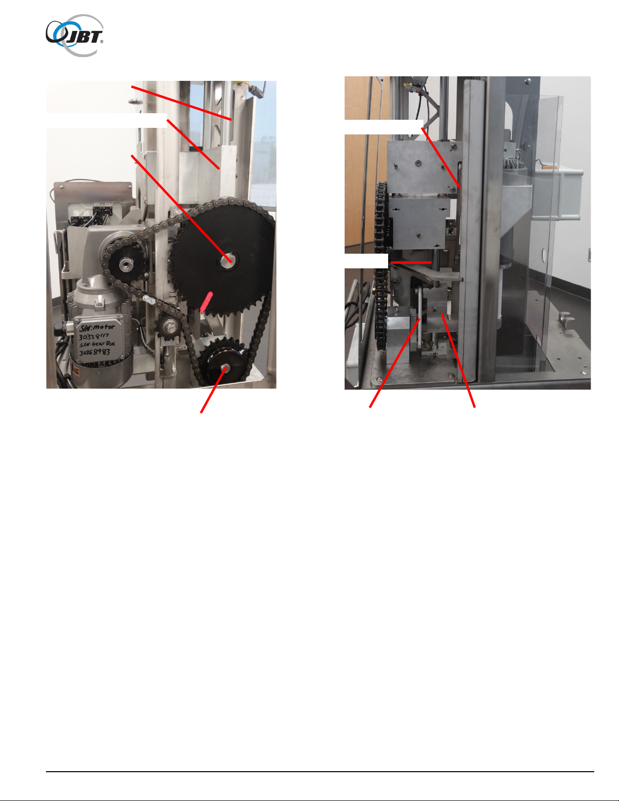
Check especially on the Sprockets, Crank Arms, Fruit Lift and Hopper.
4. Check chain for tightness.
Refer to Figure 9.
Chain should have 1/4 inch maximum slack on top side. To adjust, loosen the tensioning bolt
located on the chain tensioner until 1/4 inch of slack is measured.
CAUTION: DO NOT OVER TIGHTEN CHAIN.
5. Check chain and sprockets for rust.
Lubricate chain and sprockets should rust appear. JBT Select FG Spray (Non-Drip),
p/n 575054, is recommended.
6. Lubricate grease fittings with JBT Select 2FG grease, p/n 575066.
Figure 9. Checking Chain Slack
26 FNS-0014-060-EN June 2019 Rev A

7. Check gear motor.
If Juicer has been laid on its side for any reason (i.e., during shipping), or if there is any
evidence of oil leak, check oil level and add oil, if necessary. Refer To Figure 10.
Use FUCHS FM220 GEAR OIL FG only.
8. Check hopper.
To remove hopper, fruit lift (upper cup drive) must be in down position. Remove two spanner
screws using spanner wrench. Remove hopper.
Figure 10. Gear Motor
27 FNS-0014-060-EN June 2019 Rev A

Troubleshooting
• Juicer will not turn on
1. Juicer is not plugged into electrical outlet.
2. Building circuit breaker or GFI has tripped (reset).
3. Loose wire connection.
Check that all electrical connections are properly installed and secured.
4. On/Off power switch is disconnected
a. Unplug the juicer.
b. With the Front door open loosen the four screws holding the electrical box closed.
c. On the backside of the lid insure that the two black wires (103 and 104) are connected to the
On/Off switch.
d. If power switch is broken replace lid of electrical box or the entire box.
• Juicer starts, but shuts off
1. Juicer is tripping GFCI outlet
Certain GFCI outlets will not support the juicer. Have electrician replace with a compatible outlet.
Known compatible outlets include all models of Legrand 1597 for 15 Amp service and all models of
Legrand 2097 for 20 Amp service. Others may work as well
2. Building circuit breaker is not properly rated for 15 Amps.
3. Extension cord or wiring is too long.
Shorten extension cord or use heavier gauge wire. (See Page 6 "Electrical Specifications")
4. All covers not completely closed (including cart).
Juicer may be flexing when squeezing fruit, causing switch to open. Make sure all latches are
completely locked.
5. The hopper and door cables are reversed.
a. Unplug juicer.
b. Remove the hopper access panel.
c. Unplug the hopper and front door cables (two smaller connectors on top and farthest from
access panel).
d. Switch the cables and plug them back in.
• Juicer will not start
1. Covers are not completely closed.
Open and close both doors, make sure the sensors are securely fastened and then ensure the
doors are firmly closed.
2. Safety sensor has failed. Refer to checking safety sensors to identify broken safety sensor
and replace as necessary.
3. Loose wire inside electrical box
28 FNS-0014-060-EN June 2019 Rev A

Troubleshooting (continued)
• Safety Circuit Fault screen will not go away
1. Safety sensors are not connected properly.
a. Turn off Juicer and unplug from outlet.
b. Remove the hopper access panel.
c. Insure that all the cables on the back of the electrical box are installed and the twist locks on
the connectors are tight.
2. A safety sensor has failed.
a. Follow procedures for checking safety circuits in the “Electrical Drawings and Procedures”
section of this manual.
b. If Faulty sensor is found, replace safety sensor and cable assembly.
3. Electrical box does not support safety circuit monitoring (Only perform these steps if
previous troubleshooting steps do not fix the problem, the process will disable this function
on the juicer)
a. Click in the bottom right corner of the fault screen.
b. Enter the password for accessing the service screen.
c. Enter the second service page.
d. Turn off the safety check.
NOTE: This does not fix an issue, it just disables the screen. If performed on a juicer with this
feature, the juicer will not run. The issue must be fixed and the safety check needs to be turned
back on.
• Juicer runs extremely slowly
1. Constant speed feature has been enabled.
a. Turn juicer off and back on to correct
2. Variable frequency drive programing has been changed
a. Refer to the procedure for re-programing the VFD in the “Electrical Drawings and Procedures”
section of this manual.
b. Follow procedure at the bottom for a Factory Reset
c. Return to the top and follow procedure to program the drive from the beginning
3. PLC terminal strip not firmly connected
a. Unplug the juicer
b. Loosen the four screws on the front of the electrical box
c. On the back side of the lid make sure the green strips connected to the PLC are fully seated
29 FNS-0014-060-EN June 2019 Rev A

Troubleshooting (continued)
• Juicer stalls trying to squeeze fruit
1. Fruit has part of stem on it.
Turn off Juicer and unplug . Remove fruit from the Juicer and restart.
2. Peel is too thick.
Turn off Juicer and unplug. Remove fruit from the Juicer and restart.
3. Juicer is operating too quickly.
Use a lower speed setting on the settings page.
4. Turn off Juicer and unplug . Remove fruit from the Juicer and restart.
5. Cutter is damaged.
CAUTION: CUTTER AND KNIVES ARE SHARP.
a. Sharpen or replace cutter as specified in Maintenance section.
b. Install red protective cap onto cutter.
c. After red protective cap is installed, remove cutter. Handle cutter with care to avoid contact
with sharp edge.
• Juicer runs with covers open or off
Defective interlock switch. Replace immediately.
• Juicer emits "squealing" sound during operation
Spray food grade lubricant on all rotating parts.
Lubricate grease fittings on machine.
If noise continues, rod end or bearing may be defective.
• Scraping noise coming from hopper area
Fruit lift mechanism is dragging on hopper.
See Page 23, Item 8 under “Periodic inspection”.
NOTE: IF AN OPERATIONAL PROBLEM PERSISTS AFTER TROUBLESHOOTING,
CONTACT JBT SERVICE FOR ASSISTANCE.
30 FNS-0014-060-EN June 2019 Rev A

Rebuilding
It is best to replace all bearings at the same time.
Instructions for replacing all bearings, Refer to Service Videos for more details.
1. Remove reservoir and all juicing components.
2. Remove Front Door and All Covers, Sides and Top.
Remove hopper lid prior to removing top cover so interlock switch and cable does not need to be
removed. Place the assembled hopper lid on top of the frame.
Refer to Figures 11 and 12.
Figure 11. Juicer with All Covers Removed
31 FNS-0014-060-EN June 2019 Rev A
Upper Linear Shafts
Upper Cup Drive Assembly
Upper Rotary Shaft
Upper Drive Crank Arm
Lower Rotary Shaft
Lower Drive Crank Arm
Lower Orifice Drive Assm.
Lower Linear Shaft
Figure 12. Back View of Juicer
32 FNS-0014-060-EN June 2019 Rev A

Rebuilding (Continued)
3. With all side covers removed, use 3/16” and 5/16" Allen wrenches to loosen the set
screw and the socket head cap screw on crank arm for upper cup drive .
(Use Motor Shaft Service Tool 06010400 to rotate gear motor as necessary).
Refer to Figure 13.
Repeat above steps on crank arm for lower drive.
Refer to Figure 14.
Figure 13. Using Allen Wrench to Loosen Upper Cup Crank Arm
Figure 14. Loosening Lower Crank Arm
33 FNS-0014-060-EN June 2019 Rev A

Rebuilding (Continued)
4. Remove linear shafts.
With a 3/16" Allen wrench, loosen set screws at top and bottom of all three shafts.
Back screws out at least 1/4" to clear flats on shafts. If shafts are stuck, use bearing removal
puller with 3/8"-16 x 2" hex head cap screw to break free shafts.
(Note: Lower Shaft will be removed downward through the waste bin area)
Refer to Figure 15.
5. Lift out upper and lower drive arms with linkages still attached.
Refer to Figure 16.
6. Disassemble linkages arms from drive and crank arms.
Note location and numbers of washers and spacers.
7. Using a similar process to step 4 Remove sprockets from shafts and then shafts from
frame.
Pull or pry on large diameter upper drive sprocket, repeat for lower drive sprocket.
Refer to Figure 17.
.
Figure 15. Removal of Linear Shafts
34 FNS-0014-060-EN June 2019 Rev A

Figure 16. Removal of Upper and Lower Drive Arms with Linkages and Crank Arms
Figure 17. Loosen Set Screws and Socket Head Screws and Remove Sprockets
35 FNS-0014-060-EN June 2019 Rev A

Bearing Removal Slug – 1" (Inside)
Bearing Removal Puller
1/2-13 Nut
Bearing Removal Rod
Bearing Removal Driver
Rebuilding (Continued)
Some instructions below show the Generation 1 Juicer but the procedures are the same.
8. Remove sleeve bearings from upper and lower drive arms.
Refer to Figures 18 and 19.
Bearings can be pulled out using puller, 1" removal slug, and short threaded removal rod; or can
be driven or pressed out using driver. New bearings can be installed by compression (Figure 20)
by using installation pilot, installation washer and long threaded installation rod, or just use
installation pilot and press bearings into place. Light coat of Teflon
diameter of bearings.
®
grease can be used on outer
36 FNS-0014-060-EN June 2019 Rev A
Figure 18. Removing Bearings from Upper Drive Arm

Bearing Installation Washer
Bearing Installation Rod
Bearing Installation Pilot
Figure 19. Removing Bearings from Lower Drive Arm
37 FNS-0014-060-EN June 2019 Rev A
Figure 20. Installation of Bearings into Drive Arms

Rebuilding (Continued)
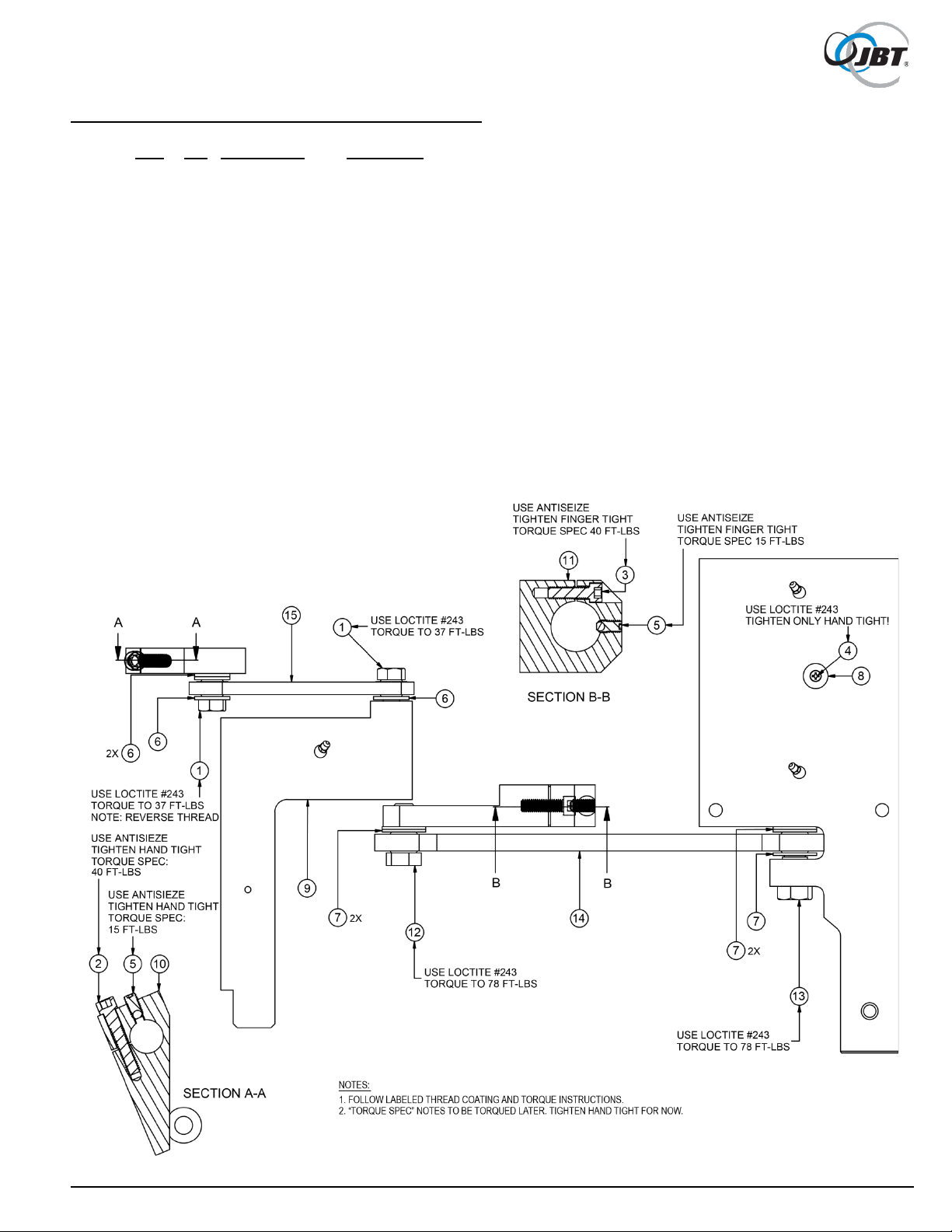
9. Reassemble rod end assemblies to drive arms, again making sure left hand threaded
ends are on the crank arms.
Refer to Figures 21 and 22.
Use Loctite #242 on all fasteners. Tighten to torques as shown. Make sure rod end lock
spacer is installed on rod end in upper drive arm. Make sure plastic bearing buttons are
installed on each side of lower drive arm.
Figure 21. Completed Assembly of Upper Cup Drive Arm
38 FNS-0014-060-EN June 2019 Rev A

Figure 22. Completed Assembly of Lower Drive Arm
39 FNS-0014-060-EN June 2019 Rev A

Rebuilding (Continued)
10. Remove sleeve bearings from main frame.
Refer to Figures 23 and 24.
The outer upper drive shaft bearing can be removed using puller, 1-1/2" removal slug, and short
threaded removal rod.
The inner bearing can be removed the same way, or can be pressed out using driver. The lower
shaft bearing can be removed the same way except using 1" removal slug. New bearings can be
installed by compression (Figure 25) by using installation pilot, installation washer, and long
threaded installation rod. Light coat of Teflon grease can be used on outer diameter of bearings to
aid in installation.
11. There are thrust washers next to each bearing on the main frame. Make sure the old
ones have been removed and new ones installed.
One side of thrust washer is plain metal. Silicone this side and glue them to the frames
(Typical 4 places).
DO NOT get silicone on surface of any bearing. Refer to Figure 26.
12. Before reassembling, check all shafts for excessive wear; replace as necessary.
Reassemble parts in the reverse order of removal. DO NOT forget to put keys back into crank
arms.
On both crank arms, be sure to tighten socket head cap screw first. And then the set screw.
Tighten fasteners to torques shown.
Lubricate all grease fittings if provided.
Figure 23. Removing Bearing from Lower Rotary Drive
40 FNS-0014-060-EN June 2019 Rev A

Bearing Removal Rod
Bearing Removal Slug 1-1/4"
Figure 24. Removing Bearing from Upper Rotary Drive
41 FNS-0014-060-EN June 2019 Rev A
Figure 25. Installation of Bearings and Thrust Washers

ROTATION
Align Marks
Rebuilding (Continued)
Figure 26. Thrust Washer on Both Sides
13. Before installing chain, align timing marks as shown.
Refer to Figure 27.
This is critical to operation of the machine. Adjust chain as shown in Maintenance section.
42 FNS-0014-060-EN June 2019 Rev A
Figure 27. Alignment of Timing Marks

Item
Part Number
Description
1
06000180
Tool, Bearing Installation Pilot
2
06000181
Tool, Bearing Installation Washer
3
06000182
Tool, Bearing Puller
4
06000183
Tool, Bearing Removal Slug 1"
5
06010507
Tool, Bearing Removal Slug 1-1/4"
6
06010508
Tool, Bearing Removal Driver
7
06000186
Tool, Bearing Installation Rod
8
06000187
Tool, Bearing Removal Rod
9
06000188
Tool, Washer, Rod End, 1/2"
10
06000189
Tool, Washer, Rod End, 5/8"
12
06010400
Tool, Adapter, Hand Crank
13
004350648
Screw, Cap, Hex, 5/8-11 x 1-1/2", C/G
14
004350571
Screw, Cap, Hex, 1/2-13 x 1-1/2", Full Thread, C/G
15
004110063
Nut, Hex,1/2-13, Grade 8 Steel
16
004815100
Washer, Plain Narrow, 1/2", C/G
17
004815080
Washer, Plain Narrow, 3/8", C/G
18
004350407
Screw, Cap, Hex, 3/8-16 x 2", C/G
19
009733032
Bit, Drilled Spanner #14, ¼ Hex (Not Pictured)
20
009998004
Bit, Spanner Insert, #8, 1/4 Hex
06010509
Kit, Tool, CJ & MFJ (Includes above Items 1 - 20)
Other Multi-Fruit Juicer Kits
06010510
Kit, Complete Overhaul w/ shafts
Cleaning Components & Other Parts
009080326
Brush, 1-1/16" x 8"
003091001
CorKlean Cleaner
009710031
Stone, Sharpening
003460053
Lubricant, W/ Teflon, 3 Oz Tube
003460057
Lubricant, W/ Teflon, 14 Oz Can
003015905
Silicone, White, 3 Oz Tube
009092018
Cutter Cap
Rebuild Tooling Kit & Spare Parts Kit, 06010509
43 FNS-0014-060-EN June 2019 Rev A
Figure 28. Rebuild Tool Kit
44 FNS-0014-060-EN June 2019 Rev A

6. Motor Mount Blocks
51
7. Bottom Bearing Block, Orifice Tube Block
52
15. Splash Guards
60
16. Splash Shield Guides, Fruit Guides
61
17. Fruit Lift, Hopper Mounting
62
25. Decals, 3-Piece, Large Logo (Optional)
70
26. Juicing Components
71
27. Self-Service Juicing Components
72
Illustrated Parts Lists
Assembly drawings in this chapter provide a list of part numbers for replaceable parts
available for the 2
provided:
Parts List / Parts Drawing Page
1. Cart, Tool Holder Mounting 46
2. Main Stainless Steel Center Frame 47
3. Center Plate 48
4. Cup Mounting Blocks, Lower Cup 49
5. Centering Drive Block 50
8. Rotating Assembly, Lower and Upper 53
9. Sliding Shafts 54
nd
Generation Multi-Fruit Juicer. The following parts list/drawings are
10. Rotating Shafts, Thrust Bearings 55
11. Wiring Routing Tabs, Weld Stubs 56
12. Chain Tensioner 57
13. Chain, Sprocket and Motor Mounting 58
14. Grease Fittings 59
18. HMI Mounting, Proximity Sensors for Float and TDC 63
19. Electrical Connections 64
20. Hopper 65
21. Hopper Top Cover, Lid and Sensors 66
22. Panels, Left and Rear 67
23. Service Panel, Right Panel 68
24. Decals (Standard) 69
28. Splash Shield, Waste Bin, Tools and Accessories 73
29. Doors, Latches and Hinges 74
45 FNS-0014-060-EN June 2019 Rev A

Item
Qty
Part Number
Description
1
1
06010103
Cart Assembly
2
1
06010291
Tool Holder
1. Cart, Tool Holder Mounting
Figure 29. Cart
46 FNS-0014-060-EN June 2019 Rev A

Item
Qty
Part Number
Description
1
12
004011032
Bolt, Carriage, 3/8-16 X 1-1/4" Lg, 304SS
2
9
004156074
Nut, Hex, S/L, Light, 3/18-16, 304SS
3
19
004816086
Washer, Flat, 3/8", SS
4
1
06010231
Frame, 2nd Gen MFJ, Machined
2. Main Stainless Steel Center Frame
47 FNS-0014-060-EN June 2019 Rev A
Figure 30. Main Stainless Steel Center Frame

Item
Qty
Part Number
Description
1
12
004011032
Bolt, Carriage, 3/8-16 X 1-1/4" Lg, 304SS
2
1
004156072
Nut, Hex, S/L, Heavy, 3/18-16, 304SS
3
7
004156074
Nut, Hex, S/L, Light, 3/18-16, 304SS
4
15
004816086
Washer, Flat, 3/8", SS
5
1
06010194
Plate, Formed, Juicing Area
3. Center Plate
48 FNS-0014-060-EN June 2019 Rev A
Figure 31. Center Plate

Item
Qty
Part Number
Description
1
2
004210030
Pin, Dowel, 3/8" Diameter X 7/8" Lg, 304SS
2
4
004210044
Pin, Dowel, 1/4" Diameter X 1-1/8" Lg, SS
3
6
004415013
Screw, Shoulder, 3/8" X 5/8" Lg, 1/2" Shoulder, 18-8SS
4
1
06010227
Cup Mount, LH
5
1
06010232
Cup Mount, RH
4. Cup Mounting Blocks, Lower Cup
Figure 32. Cup Mounting Blocks, Lower Cup
49 FNS-0014-060-EN June 2019 Rev A

Item
Qty
Part Number
Description
1
4
004415014
Screw, Shoulder, 1/2" X 3/4" Lg, 3/8-16 Thread, 18-8SS
2
4
06010069
Spacer, Alignment Block
5. Centering Drive Block
50 FNS-0014-060-EN June 2019 Rev A
Figure 33. Centering Drive Block

Item
Qty
Part Number
Description
1
4
004415051
Screw, Socket Head, 3/8-16 Thread, 3" Lg, 18-8SS
2
4
004701002
Stud, Fully Threaded, 3/8-16, 2-1/4" Lg, 18-8SS
3
2
06010071
Spacer, Right Angle Motor Mounting
6. Motor Mount Blocks
51 FNS-0014-060-EN June 2019 Rev A
Figure 34. Motor Mount Blocks

Item
Qty
Part Number
Description
1
1
003030296
Bar, Flat, Aluminum, 3" X 5"
2
4
004352397
Screw, Cap, Hex, Full Thread, 3/8-16 X 1-1/2", SS
3
16
004806070
Washer, Lock, 3/8" Reg, SS
7. Bottom Bearing Block, Orifice Tube Drive Block
Figure 35. Bottom Bearing Block, Orifice Tube Drive Block
52 FNS-0014-060-EN June 2019 Rev A
Item
Qty
Part Number
Description
1
2
004352571
Screw, Cap, Hex, 1/2-13 X 1-1/2", SS
2
2
004355051
Screw, Cap, Hex, Socket Head, 3/8-16 X 2", S/L, Alloy
3
1
004356109
Screw, Cap, Hex, Socket Head, 3/8-16 X 1-1/4", S/L,. Steel
4
1
004385057
Screw, Flat Head, Hex, 8-32 X 1/2" Lg, 304SS, Nylock, Pellet
5
9
0043541138
Screw, Cap, Hex, Socket Set Cup Point, 3/8-16
6
4
004816100
Washer, Plain N, 1/2", SS
7
5
004816120
Washer, Plain N, 5/8", SS
8
1
007143009
Counter Sunk Disc, Magnetic, 3/4" OD
9
1
06000011
Arm, Orifice Tube Drive
10
1
06000058
Crank, Orifice Tube Drive
11
1
06010242
Crank, Upper Cup Drive
12
1
06010258
Screw, Upper Cup Crank, LH
13
1
06010323
Upper Arm Bolt
14
1
06010174
Assembly, Arm, Link, Upper Cup
15
1
06010175
Assembly, Arm, Link, Orifice Drive
16
1
06000057
Lock, Rod End
8. Rotating Assembly, Lower and Upper
Figure 36. Rotating Assembly, Lower and Upper
53 FNS-0014-060-EN June 2019 Rev A

Item
Qty
Part Number
Description
1
5
004352395
Screw, Cap, Hex, 3/8 X 1, SS
2
9
0043541138
Screw, Cap, Hex, Socket Set Cup Point, 3/8-16
3
16
004806070
Washer, Lock, 3/8" Reg, SS
4
2
06000064
Upper Cup Drive Linear Shaft
5
1
06000063
Linear Orifice Drive Shaft
6
1
06010064
Block, Guide, Upper Cup Guide Rods
7
1
06010065
Block, Guide, Orifice Rod
8
6
005098731
Bearing, 1"
9. Sliding Shafts
54 FNS-0014-060-EN June 2019 Rev A
Figure 37. Sliding Shafts

Item
Qty
Part Number
Description
1
2
005062805
Washer, Thrust,1-1/2" ID X 2-1/2" OD
2
2
005098112
Thrust Washer
3
1
005576061
Key, Square, 1/4" X 3/4" Lg, 416SS
4
2
005576286
Key, Square, 3/8" X 1-1/4" Lg, 304SS
5
1
06006061
Shaft, Rotary Orifice Drive
6
1
06006101
Rotary Main Drive Shaft
7
2
005098731
Bearing, 1"
8
2
005098772
Bearing, 1-1/2"
10. Rotating Shafts, Thrust Bearings
55 FNS-0014-060-EN June 2019 Rev A
Figure 38. Rotating Shafts, Thrust Bearings

Item
Qty
Part Number
Description
1
18
004705106
Stud, Weld, Threaded Flange, #10-24 X 3/4" Lg, SS
2
20
004156041
Nut, Hex, S/L, #10-24, SS
3
5
006270314
Clamp, Chemical Resistant, 7/16" ID, 1" Line
4
1
006270317
Clamp, Chemical Resistant, 1/4" ID, 1" Line
5
3
006270318
Clamp, Chemical Resistant, 7/16" ID, 2" Line
6
9
006270319
Clamp, Chemical Resistant, 1/4" ID, 2" Line
11. Wiring Routing Tabs, Weld Stubs
56 FNS-0014-060-EN June 2019 Rev A
Figure 39. Wiring Routing Tabs, Weld Stubs

Item
Qty
Part Number
Description
1
1
004116026
Nut, Jam, 3/8-16, SS
2
1
004156118
Nut, Hex, S/L, Thin, 5/8-11, SS
3
2
004352392
Screw, Cap, Hex, 3/8-16 X 7/8" Lg, 304SS
4
1
004352415
Screw, Cap, Hex, Full Thread, 3/8-16 X 3-1/2" Lg, SS
5
16
004806070
Washer, Lock, 3/8" Reg, SS
6
1
004605030
Spacer, Unthreaded, 1" OD, 3/8" Lg, 5/8" Screw, 18-8SS
7
1
005806374
Sprocket, Idler, #60, 12T, 3/4" P, 1-9/16" Diameter
8
1
06010171
Mount, Chain Tensioner
9
1
06010355
Bolt, Idler Sprocket, Cut to Length
10
1
06010367
Chain Tensioner Washer, 5/8"
12. Chain Tensioner
57 FNS-0014-060-EN June 2019 Rev A
Figure 40. Chain Tensioner

Item
Qty
Part Number
Description
1
4
004110066
Lock Nut, Nylon Insert, Thin, 3/8-16, 18-8SS
2
2
004355051
Screw, Cap, Hex, Socket Head, 3/8-16 X 2" Lg, S/L, Alloy
3
2
004541112
Screw, Set, Hex, S/L, 5/16-18 X 3/4" Lg, C/G
4
9
004541138
Screw, Socket Set, Cup Point, 3/8-16
5
4
004701002
Stud, Fully Threaded, 3/8-16 X 2-1/4" Lg, 18-8SS
6
16
004806070
Washer, Lock, 3/8" Reg, SS
7
1
005220148
Chain, #60, Single Strand, Plus (1) Con, (1) Half Link, Steel
8
1
005576242
Key, Square, 1/4" X 1" Lg, 416SS
9
1
005804235
Sprocket, Wear Resistant, 1-1/4", 16T, ANSI60 Chain
10
1
06000065
Sprocket, Orifice Drive
11
1
06006120
Sprocket, Upper Cup Drive Arm
13. Chain, Sprocket and Motor Mounting
Figure 41. Chain, Sprocket and Motor Mounting
58 FNS-0014-060-EN June 2019 Rev A

Item
Qty
Part Number
Description
1
2
007120205
Fitting, Grease, 1/4-28 x 45mm
14. Grease Fittings
59 FNS-0014-060-EN June 2019 Rev A
Figure 42. Grease Fittings

Item
Qty
Part Number
Description
1
20
004156041
Nut, Hex, S/L, #10-24, SS
2
15
004385055
Screw, Machine, Flat Head,#10-24 X 1" Lg, Phillips Head
3
10
004816052
Washer, Plain, #10, SS
4
1
06010216
Splash Guard, Upper
5
1
06010217
Splash Guard, Lower
6
1
06010262
Upper Guard Cover, Upper Splash Guard
7
1
06010263
Lower Guard Base, Lower Splash Guard
8
1
06010264
Lower Guard Cover, Lower Splash Guard
15. Splash Guards
60 FNS-0014-060-EN June 2019 Rev A
Figure 43. Splash Guards

Item
Qty
Part Number
Description
1
2
004111048
Nut, Hex, 3/8-16, SS
2
2
004392170
Screw, Machine, Pan, #10-24 X 1/2" Lg, Phillips Head, 304SS
3
2
004397075
Screw, Round Head, Pan, 10-24 Threaded, 7/8" Lg, Phillips Head, 18-8SS
4
2
004405008
Screw, Set, Cup Point, 3/8-16 X 1-1/4" Lg, 18-8SS
5
4
004501152
Screw, Cap, Hex, S/L, 3/8-16 X 1" Lg, SS
6
16
004806070
Washer, Lock, 3/8", SS
7
10
004816052
Washer, Plain, #10, SS
8
15
004816086
Washer, Flat, 3/8", 7/8" Diameter, SS
9
1
06010207
Reservoir Slide Base
10
1
06010244
Mount, Splash Shield
11
1
06010329
Fruit Guide Kit, Small Fruit
16. Splash Shield Guides, Fruit Guides
Figure 44. Splash Shield Guides, Fruit Guides
61 FNS-0014-060-EN June 2019 Rev A

Item
Qty
Part Number
Description
1
5
004352395
Screw, Cap, Hex, 3/8" X 1" Lg, SS
2
2
004352410
Screw, Cap, Hex, 3/8-16 X 2-1/4" Lg, 304SS
3
2
004356104
Screw, Cap, Hex, Socket Head, 3/8-16 X 1" Lg, 316SS
4
52
004401023
Screw, Phillips Head, Extra Wide, 8-32 Threaded, SS
5
1
004605029
Standoff, Hex, 5/8" X 1-2/3" Lg, 18-8SS
6
4
004816080
Washer, Plain, 3/8" N, 304SS
7
15
004816086
Washer, Flat, 3/8", 7/8" Diameter, SS
8
1
06010240
Fruit Lift, Mount Block
9
1
06010243
Mount, Hopper, Bolt
17. Fruit Lift, Hopper Mounting
62 FNS-0014-060-EN June 2019 Rev A
Figure 45. Fruit Lift, Hopper Mounting

Item
Qty
Part Number
Description
1
4
004011032
Nut, Hex, 1/4-20, SS
2
4
004156014
Nut, Hex, S/L, 4-40, SS
3
4
004156053
Nut, Hex, S/L, Light, Thin, 1/4-20, 304SS
4
4
004356064
Screw, Cap, Socket Head, 1/4-20 X 1-1/4" Lg, SS
5
4
004396116
Screw, Round, Bind, Slot, Extra Wide, 4-40 Threaded, 5/8" Lg, SS
6
52
004401023
Screw, Phillips, Extra Wide, 8-32 Threaded, 1/4" Lg, SS
7
4
004816060
Washer, Plain, 1/4" N, SS
8
6
004816095
Washer, #6, .149" ID, .625" OD, Oversized, 304SS
9
1
06010118
Electrical Panel Assembly
10
2
06010305
Proximity Switch Assembly, Normally Open Connection
11
1
06010306
TDC Sensor Bracket
18. HMI Mounting, Proximity Sensors for Float and TDC
Figure 46. HMI Mounting, Proximity Sensors for Float and TDC
63 FNS-0014-060-EN June 2019 Rev A

19. Electrical Connections
Figure 47. Electrical Connections
64 FNS-0014-060-EN June 2019 Rev A

Item
Qty
Part Number
Description
1
1
06010162
Hopper Assembly
2
2
06010254
Screw, Spanner, Hopper
20. Hopper
65 FNS-0014-060-EN June 2019 Rev A
Figure 48. Hopper

Item
Qty
Part Number
Description
1
6
004156032
Nut, Hex, S/L, Light, 8-32, 304SS
2
8
004385178
Screw, Span, Flat, 8-32 Threaded, 3/4" Lg, 18-8SS
3
52
004401023
Screw, Phillips, Extra Wide, 8-32 Threaded, 1/4" Lg, SS
4
1
006090018
Plug, Knockout, 7/8" ID Hole, Gray Nylon
5
2
009080421
Rubber Push-In Bumper with Tight-Grip Stem
6
2
009284961
Torque Hinge, Concealed, SS
21. Hopper Top Cover, Lid and Sensors
Figure 49. Hopper Top Cover, Lid and Sensors
66 FNS-0014-060-EN June 2019 Rev A

Item
Qty
Part Number
Description
1
12
004011032
Bolt, Carriage, 3/8-16 X 1-1/4" Lg, 304SS
2
4
004100004
Nut, Cap, Acorn, High Crown, #8-32, SS
3
4
004100018
Nut, Cap, Acorn, 3/8-16, SS
4
14
004156166
Nut, Acorn, Lock, Distorted Thread, 8-32. 18-8SS
5
4
004260017
Rivet, Pop, 1/8", SS
6
14
004385174
Screw, Round, Drilled Spanner, Extra Wide, 8-32 X 1/2", SS
7
52
004401023
Screw, Phillips Head, Extra Wide, #8-32 Threaded, SS
8
2
004510107
Screw, Button Head, 3/8-16 X 1" Lg, Philips, 18-8SS
9
15
004816086
Washer, Flat, 3/8", SS
10
14
004816105
Washer, Oversized, #8, 18-8SS
11
2
009284050
Female Hinge
12
1
01503948
Name Plate
13
1
06006311
Side Cover, LH
14
1
06006312
Glass, LH Side
15
1
06010179
Bracket, Handle, Right
16
1
06010180
Handle, MFJ Cart
17
1
06010209
Gasket, Window
22. Panels, Left and Rear
67 FNS-0014-060-EN June 2019 Rev A
Figure 50. Panels, Left and Rear

Item
Qty
Part Number
Description
1
6
004156032
Nut, Hex, S/L, Light, 8-32, 304SS
2
4
004385178
Screw, Span, Flat, 8-32 Threaded, 3/4" Lg, 18-8SS
3
2
004392175
Screw, Machine, Pan, 8-32 X 3/4" Lg, 304SS
4
52
004401023
Screw, Phillips, Pan, Extra Wide, 8-32 Threaded, 1/4" Lg, SS
5
1
06010349
Cover Assembly, RH Side
23. Service Panel, Right Panel
Figure 51. Service Panel, Right Panel, Decals
68 FNS-0014-060-EN June 2019 Rev A

Item
Qty
Part Number
Description
1
1
009450032
Decal, Fresh N' Squeeze Logo
2
1
009450040
Decal, Cleaning Components
3
1
06000104
Decal, Warning Label, Sheer/Hand Crush, English/Spanish
24. Decals (Standard)
69 FNS-0014-060-EN June 2019 Rev A
Figure 52. Decals (Standard)

Item
Qty
Part Number
Description
1
3
009450245
Decal, MFJ, Logo, Fresh 'N Squeeze, 10.25" X 22", Matte, Vinyl
25. Decals, 3-Piece, Large Logo (Optional)
Figure 53. Decals, 3-Piece, Large Logo (Optional)
70 FNS-0014-060-EN June 2019 Rev A

Item
Qty
Part Number
Description
1
1
004220037
Pin, Quick Release, Ring Grip
2
1
004406003
Screw, Machine, Round, #4-40 X 3/16" Lg, 304SS
3
1
06000004
Cup, Lower, Machined
4
1
06000022
Nozzle, Straight, FDA Grade
5
1
06000027
Cup, Upper, Assembly
6
1
06000225
Cutter and Knives, Machined
7
2
06000098
Nut, Spanner
8
1
06000108
Manifold, Juice
9
1
06010073
Screw, Spanner
10
1
06010143
Tube, Orifice, Snap In
11
1
007486119
O-Ring, Nozzle, Viton, 1/16" Section
26. Juicing Components
71 FNS-0014-060-EN June 2019 Rev A
Figure 54. Juicing Components

27. Self-Service Specific Juicing Components
Item
Qty
Part Number
Description
1
1
06010494
Handle Momentary
1a 1 06010495
Handle Continuous
2
1
06010485
Spout Cap
3
1
06010482
Spout Body
4
1
06010479
Self-Service Housing
5
1
06010442
Manifold with Vent
6
1
06010429
Drip Tray Cover
7
1
009210043
Seat Cup
8
1
009210042
Stem
9
1
009210041
Spring
10
1
007486119
O-Ring Nozzle
Figure 55. Splash Shield, Waste Bin, Tools and Accessories
72 FNS-0014-060-EN June 2019 Rev A

Item
Qty
Part Number
Description
1
1
003091001-2
Cleaner, Corklean, 2 lbs
2
1
009080327
Brush, Dish
3
1
009080328
Brush, Tube, 1"
4
1
009092018
Cap, Cover
5
1
009092023
Waste Container, 21" X 17" X 12", Polyethylene, Grey
6
1
009710031
Stone, Sharpening, Half Round
7
1
06000077
Tool, Wrench, 5/16" Diameter
8
1
06000084
Rod, Orifice Clean Out
9
1
06001127
Cleaning Component Kit
10
1
06010188
Splash Shield
11
1
06010359
Triple Fruit Sizer, Hand-Held
28. Splash Shield, Waste Bin, Tools and Accessories
Figure 56. Splash Shield, Waste Bin, Tools and Accessories
73 FNS-0014-060-EN June 2019 Rev A

Item
Qty
Part Number
Description
1
2
004385176
Screw, Span, Pan, 8-32 Threaded, 5/8" Lg, 18-8SS
2
1
06010146
Drip Tray Weldment
3
1
06010147
Drip Tray Cover
4
1
06010315
Door Assembly
4a
1
06010411
Self Service Door Assembly
29. Door, Latches and Hinges
74 FNS-0014-060-EN June 2019 Rev A
Figure 57. Door, Latches and Hinges

Parts List / Parts Drawing
Page
31. VFD Enclosure Assembly, 06010366
77
32. Electrical Panel Assembly, 06010118
78
Electrical Drawings and Procedures
Electrical drawings in this chapter provide a list of part numbers for replaceable parts
available for the 2
provided:
30. Drive, Motor Wiring, 3-Phase, 230V/460V, 50 Hz/60 Hz, 06010357 76
Wiring Schematic, Electrical Panel 81
Wire Table, Electrical Panel 83
33. Programming the VFD 84
34. Procedure to Check Safety Cable Assemblies 85
35. PLC Battery Replacement Procedure 92
nd
Generation Multi-Fruit Juicer. The following parts list/drawings are
75 FNS-0014-060-EN June 2019 Rev A

Item
Qty
Part Number
Description
1
1
005617345
Gear Motor, Worm,1.5 HP,3 PH, 230V/460V, 50,Hz/60Hz, 1:25 Gear, 1.25 Shaft
2
1
06010366
VFD Enclosure Assembly
30. Drive, Motor Wiring, 3-Phase, 230V/460V, 50 Hz/60 Hz, 06010357
Figure 58. Drive, Motor Wiring, 3-Phase, 230V/460V, 50 Hz/60 Hz
76 FNS-0014-060-EN June 2019 Rev A

Item
Qty
Part Number
Description
1 1 06010360
Enclosure, VFD, Add Holes
2 1 06010358
Back Panel, VFD
3 1 06010317
HMI-VFD Power Cord
4 1 06010316
VFD-Motor Power Cord
5 1 06010314
HMI-VFD Signal Cord
6 1 06010311
Rear Enclosure Bracket
7 1 006280536
VFD, 115/230V, 50Hz/60Hz, 1.5 HP-2 HP, UL
8
12
004816052
Washer, Plain, #10, SS
9 4 004401023
Screw, Phillips head, Extra Wide, 8-32" Threaded, 2/8" Lg
10
4
004356062
Screw, Cap Socket, 1/4-20 X 1: Lg, SS
11
8
004156042
Nut, Hex, S/L,Thin,10-24, 304SS
12
4
004111032
Nut, Hex, 1/4-20, SS
13
4
004011051
Bolt, Carriage,10-24 X 1/2" Lg, Square Neck, Full Thread, SS
31. VFD Enclosure Assembly, 06010366
Figure 59. VFD Enclosure Assembly
77 FNS-0014-060-EN June 2019 Rev A

Item
Qty
Part Number
Description
1 3 003435022
Gasket, Flange, 0.862", Shell Size 13, Neoprene
2 2 003435023
Gasket, Flange, 1.1", Shell Size 17, Neoprene
3
20
004260007
Rivet, Blind, 1/8" Diameter X 7/16" Lg, SS
4 4 004397137
Screw, Machine, Round, 10-24 X 3/8" Lg, 304SS
5
20
Purchased
Rivet Washer
6
10
006010046
Strip, Terminal, Type UK5N
7 1 006010047
Din Rail, Perforated,1.5" 89 mm (3.5")
8 1 006010047
Din Rail, Perforated, 1.5" 137 mm (5.4")
9 1 006010048
Barrier, End, Type D-UK 4/10
10
2
006010049
Bar, Jumper, FB1 10-6, (Jumps 10 Terminals)
11
1
006020076
Circuit Breaker, On/Off, Metal, 28V
12
1
006070033
Contactor,12-600CAV, 50-60 Hz, 12-220 VDC
13
1
006070100
Connector, Housing, 9-Pole, Female Push In, Nylon,11A
14
1
006070101
Connector, Housing, 9-Pole, Male Push In, Nylon,11A
15
1
006070102
Connector, Housing, 6-Pole,Female Push In, Nylon,11A
16
1
006070103
Connector, Housing, 6-Pole, Male Push In, Nylon,11A
17
19
006070104
Connector, Push In, Female, 13.5A 20AWG-14AWG, Brass
18
19
006070105
Connector, Push In, Male,13.5A 20AWG-14AWG, Brass
19
1
006070106
Connector, Male, Signal/Power, Push-In, 4-Pole,14A
20
1
006070107
Connector, Female, Signal/Power, Push-In, 4-Pole,14A
21
27
006080138
Connector Pin, Male, 20-24 GA, 13A, Plated Brass
22
1
006090376
Enclosure, Polycarbonate,10.9" X 7.4" X 7.1", Insulated, Sealed
23
1
006160071
Relay, Overload, 12-16A
24
1
006160110
Relay, Din Rain Mount, 24V,12mA, 6A Rating, 400 VAC
25
1
006160136
Safety Relay, Din Rail Mount, 24 VAC, 24 VDC
26
2
006210482
Terminal Block, Double Level, 26 AWG-12 AWG, 20A, 300V
27
2
006220044
Terminal, Q-Disc, Flame Retardant, 90 Degree, 12-10 AWG, Yellow
28
2
006221106
Terminal, Ground, Type USLKG25
29
2
006221179
Terminal Block, End Cover, Gray Plastic
30
3
006221180
End Stop, Din Rail 1, 3, Gray, IP20
31
1
006260041
Wire, Stranded, 22AWG, 300V, AC, Tin Plated, Black5
32
1
006260042
Wire, Stranded, 22AWG, 300V, AC, Tin Plated, Red
33
1
006260043
Wire, Stranded, 22AWG, 300V, AC, Tin Plated, Blue
34
1
006260044
Wire, Stranded, 22AWG, 300V,AC, Tin Plated, Brown
35
1
006260045
Wire, Stranded,12AWG, 300V, AC, Tin Plated, Black
36
1
006260047
Wire, Stranded,12AWG, 300V, AC, Tin Plated, Green
37
1
006260048
Wire, Stranded,12AWG, 300V, AC, Tin Plated, White
38
3
006270199
Connector, Housing, 9-Pin, Male
39
1
006280578
Power Supply, 100-240 VAC, 50-60 Hz, 60W
40
1
006280643
Touch Screen, PLC HMI ,4.3" Screen, 24VDC
41
1
006280822
Module, Serial Port, Comm
42
3
007660098
Seal, Peripheral, SZ 13
43
2
007660099
Seal, Peripheral, SZ 17
44
6
009097007
Cable Holder, ADH, Plastic,1/4" Diameter, 5/8" X 3/8" X 3/4"
45
1
06010253
Control Panel Gasket
46
1
06010259
Bezel, Control Panel
47
1
06010271
Back Panel
48
2
06010319
3-Conductor Receptacle
49
1
Purchased
Safety Label, Read Operators Manual
50
1
Purchased
Safety Label, Danger Risk Of Electrical Shock
32. Electrical Panel Assembly, 06010118
78 FNS-0014-060-EN June 2019 Rev A

Figure 60. Electrical Panel Assembly (Sheet 1 of 2)
79 FNS-0014-060-EN June 2019 Rev A

Figure 61. Electrical Panel Assembly (Sheet 2 of 2)
80 FNS-0014-060-EN June 2019 Rev A
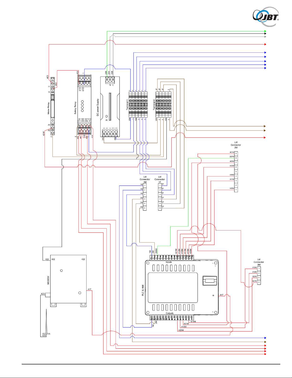
Figure 62. Wiring Schematic, Electrical Panel (Sheet 1 of 2)
81 FNS-0014-060-EN June 2019 Rev A

Figure 63. Wiring Schematic, Electrical Panel (Sheet 2 of 2)
82 FNS-0014-060-EN June 2019 Rev A

Figure 64. Wire Table, Electrical Panel
83 FNS-0014-060-EN June 2019 Rev A

Setting
New Value
Purpose
0.01
05.00
Motor Amps
0.04
0002
Setting to enable operation with GFCI outlets
1.01
0002
Disable the Reverse button
1.05
0004
Auto restart all faults except short circuit (PLC also has its own restart)
1.07
0001
Number of restart attempts
2.02
0002
Disables up or down buttons (does not apply during programing)
** WARNING: Machine will start after next setting is entered. Make sure all safeties are in place
before the value is entered**
2.03
0002
Disables the Local mode (Local/Remote button on VFD)
3.01
15.00
Lower frequency limit (changing this will disrupt normal operation)
3.02
90.00
Upper frequency limit (changing this will disrupt normal operation)
3.03
000.2
Acceleration speed
3.04
000.3
De-acceleration speed
4.04
0001
Display the motor current
4.05
0001
Display the motor voltage
5.00
0001
Enables the motor stall detection
33. Programming the VFD
1. With the machine plugged in, turn the power on using the button next to the touch screen.
2. Ensure that both the hopper door and front door are firmly closed.
3. Press the green Start button on the touch screen.
4. At the back of the machine, remove the cover over the VFD.
5. Make sure the Stop LED at the top is lighted. If it is not, press the “Run/Stop” button.
6. Press the “Program/Display” Button until the PGM LED is on.
7. Use the “</Reset” button to change which digit is flashing.
8. Use the “^” and “v” buttons to change the selected digit
9. When the proper setting is selected, press “Read/Enter” to display the current value
10. If necessary, use the arrow buttons from Step 7 and 8 to change the value
11. Once proper value has been entered, press “Read/Enter” and move to the next (if value is
already correct then press “Read/Enter” without changing anything)
12. The screen should display “END” then return to the setting.
13. Again use buttons from step 7 and 8 to select the next setting.
14. Settings to be changed (left column) and the value to change to (right column - take note of the
decimal place each time a value is entered as it is not always in the same place):
15. When complete, replace the cover on the VFD.
16. Return to the touch screen and acknowledge the error and power the machine off and back on.
17. Machine should be ready to run.
To Factory reset the Drive:
1. Complete step 1 thropugh step 8 above.
2. Go to setting 6.10.
3. Change the value to “1111” and press the “Read/Enter” button.
4. VFD is now ready to be reprogrammed, return to step 7 above.
84 FNS-0014-060-EN June 2019 Rev A

34. Procedure to Check Safety Cable Assemblies
If either of the following occurs, there is likely an issue with one of the safety sensors found on
the MFJ:
• Pressing the start button but nothing happens.
• The safety circuit fault screen appears and all cables are plugged in.
In these cases, which safety has failed will need to be determined before it can be replaced.
Tools that are necessary for this procedure:
• Digital multimeter – preferably with audible continuity
• Spanner bit
• A second person to actuate the sensors is helpful, but not necessary (simply involves
holding magnet up to the sensor and removing it)
Necessary steps:
1. Power off the machine and unplug it from the wall.
2. Remove one of the safety magnets to use manually on the sensors. Refer to Figure 65.
Figure 65. Location of Front Door Safety Magnet
3. Remove the side access panel on the hopper to access the rear of the electrical panel.
Refer to Figure 66.
85 FNS-0014-060-EN June 2019 Rev A

Figure 66. Hopper with Side Access Panel Removed
4. The safety cables will need to be disconnected. These are the two connectors on the top
far side of the panel; each has two cables coming out of them. Refer to Figure 67.
Figure 67. Location of Safety Cables
86 FNS-0014-060-EN June 2019 Rev A

5. Bring the connectors to the side panel so they can be accessed with the multimeter.
Refer to Figure 68.
Figure 68. Access to Connectors
6. Locate the numbers and the socket associated with each connector.
Refer to Figure 69.
Figure 69. Connector Numbering
7. Select the connector for the front door safety.
8. Place the multimeter’s leads into sockets 4 and 7. Refer to Figure 70.
Figure 70. Multimeter Lead Positions
NOTE: At this point, it is beneficial to have someone assist. If no one is available, it will
be necessary to hold the leads in the sockets with one hand. Refer to Figure 71.
87 FNS-0014-060-EN June 2019 Rev A

Figure 71. Holding Multimeter Leads
9. While holding the leads to the connector, take the magnet removed from the door
previously and align it with the sensor. Refer to Figure 72.
10. If the sensor is working properly, there should be continuity between these sockets.
11. Remove the magnet and the sockets should lose continuity. It is important to remove the
magnet and check for loss of continuity because the sensor can become stuck in the on
position. Therefore, it needs to be confirmed that the sensor turns off and on.
12. If the multimeter does not see continuity, make sure that the magnet is lined up properly.
Remove it and line it up again (sometimes if the magnet is held up to the sensor crookedly
at first, the sensor will not register it and the magnet must be pulled away and realigned).
Also check that the multimeter leads are still firmly set in the appropriate sockets. It is
easy for them to slip while trying to position the magnet
13. If the magnet was aligned correctly, the leads are firmly in their correct sockets, and there
is still no continuity, then the sensor is bad and will need to be replaced. Continue onto
the next sensor to make sure it is still working properly and does not need to be replaced
as well. Alternatively, if continuity is detected all the time even when the magnet is not
present, then the safety is bad and needs to be replaced.
Figure 72. Magnet Positioning
88 FNS-0014-060-EN June 2019 Rev A

14. If the sensor is working properly, move the leads to sockets 8 and 9. Refer to Figure 73.
Figure 73. Multimeter Leads, Sockets 8 and 9
15. Align magnet with the sensor or have your assistant hold it to the sensor. Refer to Figure 74.
Figure 74. Magnet Positioning
16. As with before, if the sensor is working, continuity shuld exist when the magnet aligns
with the sensor and turn off when the magnet is removed.
17. Once completed with the door sensor, set that connector aside and select the hopper
safety’s connector.
18. The same process is repeated starting with placing the leads in sockets 4 and 7 again.
Refer to Figure 75.
Figure 75. Multimeter Leads, Sockets 4 and 7
89 FNS-0014-060-EN June 2019 Rev A

19. Align the magnet with the sensor in the top corner of the hopper’s lid. The magnets are
not coded and work for either sensor. Refer to Figure 76.
Figure 76. Magnet Positioning
20. Repeat the procedure from before; if continuity is detected when magnet is present and
shuts off when removed, the safety is okay.
21. If no continuity is not detected or always detected, realign the magnet and check the
position of the leads. If the problem persists, the safety needs to be replaced.
22. Once completed, move the leads to sockets 8 and 9 on the connector.
Refer to Figure 77.
Figure 77. Multimeter Leads, Sockets 8 and 9
23. As before, align the magnet and check for continuity. If continuity is detected when
magnet is present and shuts off when removed, the safety is okay. If no continuity is
detected or always detected, realign the magnet and check the position of the leads.
If the problem persists, the safety needs to be replaced.
24. Replace the necessary safety sensor and cable assemblies.
25. Reattach the connectors to the back of the electrical panel. Attach the hopper connector
first to the furthest receptacle. If the door connector is attached first, it is more difficult to
attach the hopper connector.
26. Make sure the juicer is working properly.
27. Open the front door and make sure the correct screen appears on the touch screen.
If the hopper open screen appears while the front door is open, then the connectors are
put on the wrong receptacle and need to be switched.
90 FNS-0014-060-EN June 2019 Rev A

35. PLC Battery Replacement
When the PLC battery needs to be replaced, the following message will be displayed on the Operator
Screen:
The machine can continue to be operated, but eventually the battery will fail and the control system will
lose some functionality. Saved data, such as cycle count, service phone number and service date, could
be lost and would have to be re-entered. To prevent loss of control system functions, JBT recommends
replacing the battery as soon as possible following a low battery warning message.
Recommended replacement battery: Renata CR2450N (alternative batteries may not work)
Necessary steps:
1. Before powering down the machine, take a picture of the status screen or record the cycle
count, phone number, and machine serial number (battery removal can occasionally cause
these values to be lost, requiring them to be re-entered).
2. Disconnect power plug.
3. Using a flat head screwdriver, open the main electrical box.
NOTE: To prevent plastic screw damage, insert screwdriver into the deeper slot of the plastic
screw, as shown in Figure 78.
Figure 78. Opening Main Electrical Box
4. Disconnect the cable harnesses in order to remove the lid. Refer to Figure 79.
Figure 79. Disconnect Cable Harnesses
91 FNS-0014-060-EN June 2019 Rev A

5. Be careful when removing the black wires on the overload. If possible, hold the overload
itself and rock the connector back and forth to remove the black wires. Refer to Figure 80.
Figure 80. Disconnect Overload Connections
6. Place the lid on a clean flat surface with the touch screen facing down, make sure there is
nothing that will scratch or harm the screen. Setting on a clean cloth is preferable.
7. Locate the two green wire terminal strips on the PLC (large black device on the inside of the
lid) and detach both of them. May need to use a flat head screwdriver to gently pry them out
(wires can be left connected to the wire clamps). Refer to Figure 81.
Figure 81. Detach Terminal Strips
Use a phillips head screwdriver to remove the four screws located in the corners of the PLC
cover. Do not remove the screws that come off the sides of the PLC. Refer to Figure 82.
Figure 82. Location of PLC Cover Screws (4)
92 FNS-0014-060-EN June 2019 Rev A

8. Grip the upper circuit board by the two green strips and gently lift up. If necessary, hold the
lower circuit board in place while lifting upper circuit board.. Refer to Figure 83.
Figure 83. Upper Circuit Board Removal
9. Locate, remove and replace the bad battery with a new battery (CR2450N). One side of the
battery housing has a cutout. Lift the battery up from this side and pull out of the housing.
Replace with new battery.. Refer to Figure 84.
NOTE: Make sure new battery is clean and free of smudges and firmly seated.
A loose battery can cause a battery warning message to be displayed even for a new
battery.
Figure 84. Battery Replacement
93 FNS-0014-060-EN June 2019 Rev A

10. THIS STEP IS VERY DELICATE - PROCEED CAUTIOUSLY.
a. Reinstall the circuit board that was removed, there are two sets of pins on the circuit
board that must be lined up on connectors. Refer to Figure 85.
Figure 85. Align Circuit Board Pins and Reinstall
b. To do this, find the side of the PLC with a small notch on it and find the small piece on the
edge of the board that lines up with this.. Refer to Figure 86.
Figure 86. Location of Notch on Side of PLC
c. Make sure the board lines up with the housing. As seen in the picture above, the ends of the
green strip should match to the PLC housing.
94 FNS-0014-060-EN June 2019 Rev A

d. Gently push the board down until the green strip is resting on the housing. Refer to Figure 87
Figure 87. Gently Push Down on Board
11. Replace the back cover of the PLC.
12. Reinsert the four screws that were removed from cover. There are two different size screws
used, the short ones go to the lower end of the cover while the longer screws are on the
higher end, closest to the on and off switch.
Refer to Figure 88.
Figure 88. PLC Cover Screws
13. Reattach both green wire terminal strips. Use the numbering system on the PLC to
insure the proper connections.
The terminal strip with 6 wires goes on the side with 0V over the 1 position and V+ over
the 15. The terminal strip with 9 or 10 wires (depending on model) goes on the side with
I0 under 15 and V+ under 1. Refer to Figure 89.
Figure 89. Reattach Terminal Strips
95 FNS-0014-060-EN June 2019 Rev A

14. Insure both terminal strips are firmly seated. Leaving them loose can lead to intermittent
issues during operation or leave the machine unable to run. Refer to Figure 90.
Figure 90. Firmly Seat Terminal Strips
15. Reattach electrical box lid including the two black wires and three cable harnesses that were
disconnected in Step 4.
16. Close electrical box and tighten plastic screws with flat head screwdriver.
17. Reconnect electrical plug.
18. Power up the machine and ensure that the battery warning message does not reappear.
(If the new battery was not properly seated, the warning message will likely appear within
5 seconds after the JBT screen clears.).
NOTE: If battery warning message reappears, repeat the procedure making sure the new
battery is smudge-free and firmly seated. If problem persists, repeat the procedure with a
different new battery.
19. If the battery warning screen does not reappear, battery replacement was successful.
Check the status screen to determine if service data was saved. If not, enter the service
screen and reset all necessary data.
96 FNS-0014-060-EN June 2019 Rev A
 Loading...