

November 2017
Operator & Service Manual
Citrus Juicer

2 FNS-0006-060-EN November 2017 Rev F
Operator & Service Manual
Citrus Juicer
Copyright © John Bean Technologies Corporation 2017
JBT Corporation
400 Fairway Avenue
Lakeland, FL 33801
(863) 683-5411
Manual No. FNS-0006-060-EN

3 FNS-0006-060-EN November 2017 Rev F
Safety Information ···················································· 4
Safety Instructions ···················································· 5
Technical Specifications ············································ 6
General Information ························································ 7
Operating Instructions ·············································· 10
Cleaning Instructions ················································ 12
Maintenance ···························································· 16
Periodic Inspection ··················································· 19
Troubleshooting-Operator ········································· 21
Troubleshooting-Service ·········································· 24
Rebuilding ······························································· 27
Rebuild Tooling Kits ················································· 42
Drive Parts······························································· 44
Juicing Parts ···························································· 46
Cart Assembly Enclosed Parts ··································· 48
Electrical Parts (110 Volt) ·········································· 50
Electrical Parts (220 Volt) ·········································· 54
Electrical Box Assembly ············································ 56
Cover Parts ······························································ 58
Hopper Parts – Low Profile ········································ 60
Hopper Parts – High Capacity (Round) ························ 62
Waste Container Assembly ········································ 64
Miscellaneous Parts ·················································· 66
Manual Code
Rev.
No.
Date
Pages
Change History
FNS-0006-060-EN
A
5/6/15
Entire manual
Updates, modifications and alignment to JBT global version
control and inventory standards
FNS-0006-060-EN
B
12/15/15
Entire manual
Addition of new Fresh 'n Squeeze logo
FNS-0006-060-EN
C
7/19/16
50, 51, 52. 53, 56
Updates to part numbers and/or drawings for assemblies
060-02005, 060-02005-01, 060-02005-02, 060-02003
FNS-0006-060-EN
D
12/14/16
64
Update to part description 060-00296
FNS-0006-060-EN
E
1/19/17
50, 52, 53
Addition of information for motor conversion kit, 060-10157
FNS-0006-060-EN
F
11/10/17
Entire manual
Edits and additions
Important Safety Information
You can help prevent personal injury and/or property damage.
Please read this manual carefully before operating the JBT Corporation Citrus Juicer.
DO NOT attempt any operation until you understand exactly how the machine functions.
If uncertainty remains after studying this manual, please contact:
The local JBT Corporation service representative in your country.
We're here to help. With proper handling, the JBT Corporation, Fresh ‘n Squeeze Citrus Juicer
will provide safe, efficient and convenient service for years to come.
Revision History
John Bean Technologies Corporation
JBT Corporation
400 Fairway Avenue
Lakeland, FL 33801
863.683.5411
or
4 FNS-0006-060-EN November 2017 Rev F
5 FNS-0006-060-EN November 2017 Rev F
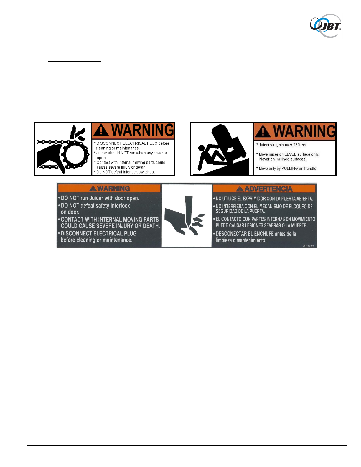
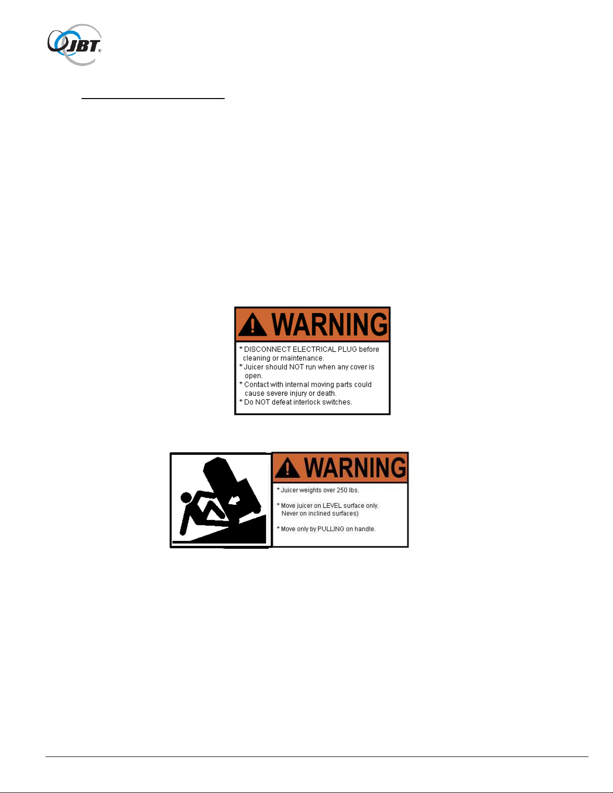
Safety Labels
The safety labels shown below appear on the Citrus Juicer. They provide essential instructions
on how to avoid possible hazards.
Please, for your safety: FOLLOW THOSE INSTRUCTIONS AT ALL TIMES.
Should the Citrus Juicer safety labels become damaged or unreadable, contact JBT Corporation
for replacement labels.
Safety Instructions
Carefully review the following safety instructions.
Make them a habit when using the JBT Corporation Citrus Juicer.
1. If Citrus Juicer continues to run when any access cover is open, interlock switch is
defective.
Turn Juicer off and unplug immediately. Call for service.
2. Prevent unauthorized access to Citrus Juicer by locking all covers with supplied key.
3. NEVER attempt to make any safety device inoperative.
4. NEVER operate or perform maintenance or repair work on Citrus Juicer when
taking any kind of drug or sedative, when under the influence of alcohol, or when
fatigued.
5. ALWAYS check adjustment of all nuts, bolts, and screws after installation, repair,
or periodic maintenance.

6 FNS-0006-060-EN November 2017 Rev F
Technical Specifications
Fruit Size: ········································ 2-1/2” to 3-1/4" major diameter
Oranges - FL: ···································· 125 to 80 count
Oranges - CA: ··································· 138 to 88 count
Lemons, Limes: ································· 138 to 115 count
Holding capacity: ······························· 15 to 20 fruit
Speed: ············································· 10 fruit/minute
Waste container capacity: ···················· 30 to 40 fruit
Optional for customer to put hole in counter.
Optional cart and waste container on wheels available.
Electrical Specifications
115V 60HZ Single Phase
Or
230V 50HZ Single Phase
12 GA. wire - up to 100 ft. from main breaker panel or
10 GA. wire - up to 200 ft. from main breaker panel
Shipping Specifications
Machine without cart: With cart:
Height: 32" 62"
Width: 18" 24"
Depth: 22" 22"
Weight: 200 lbs. 250 Ibs.

7 FNS-0006-060-EN November 2017 Rev F
General Information
The JBT Corporation Citrus Juicer is designed to provide years of dependable service. It
uses a unique patented design to extract every available amount of juice from the fruit with
the least amount of peel oil. The peel is completely separated from the juice and juice sacs
before being compressed and strained.
The machine will juice oranges, lemons, limes, tangerines, etc., without changing or
adjusting parts. In fact, different varieties of fruit can be juiced to create various fruit juice
blends.
Clean up is simple, requiring disassembly of only five parts. All waste material - peel,
membranes, and seeds - is collected for easy removal and disposal.
The Citrus Juicer is solidly built using heavy-duty components in all assemblies, including
the drive. It is simple to operate and uses a minimal number of parts.
ALWAYS follow cleaning and maintenance schedules in this manual to prevent equipment
damage.
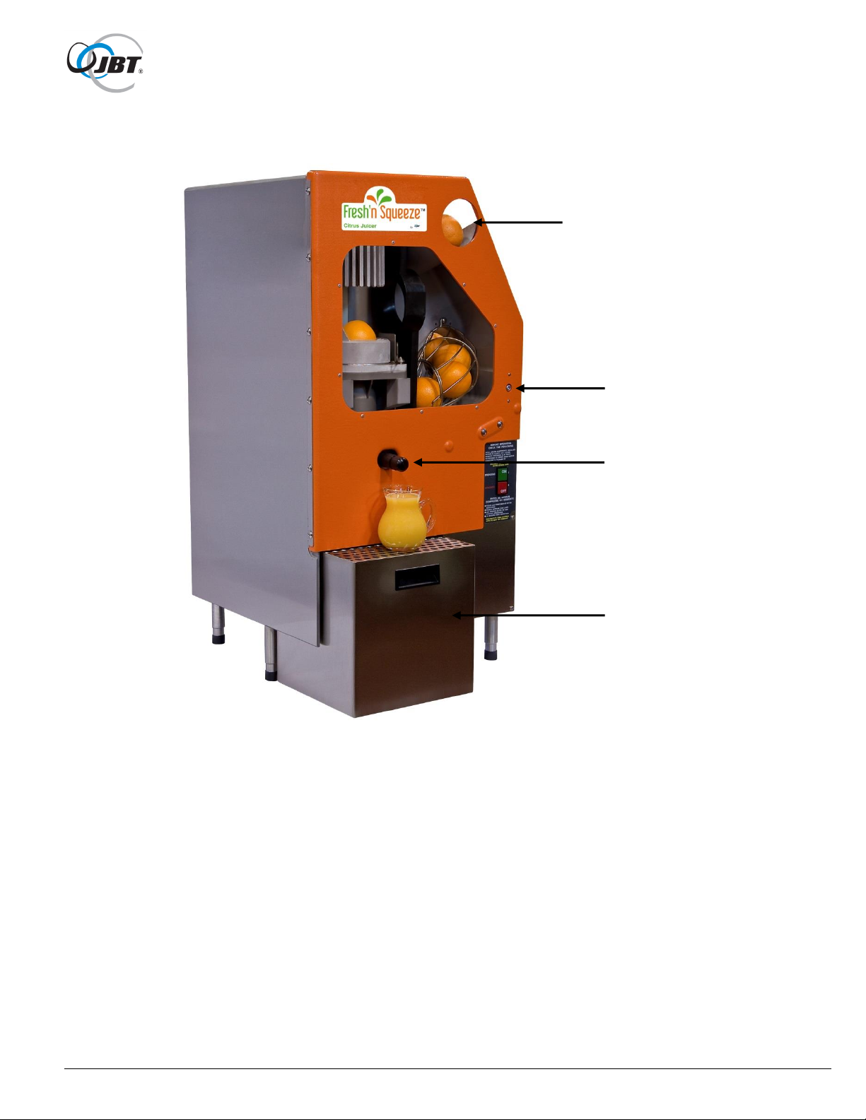
For a quick introduction to the JBT Corporation Citrus Juicer, please review the diagram on
the next page.
8 FNS-0006-060-EN November 2017 Rev F
Figure 1a. JBT Corporation Citrus Juicer
Single
Feed Hole
1/4 Turn
Lock
Juice Nozzle
Counter Top
Waste
Container
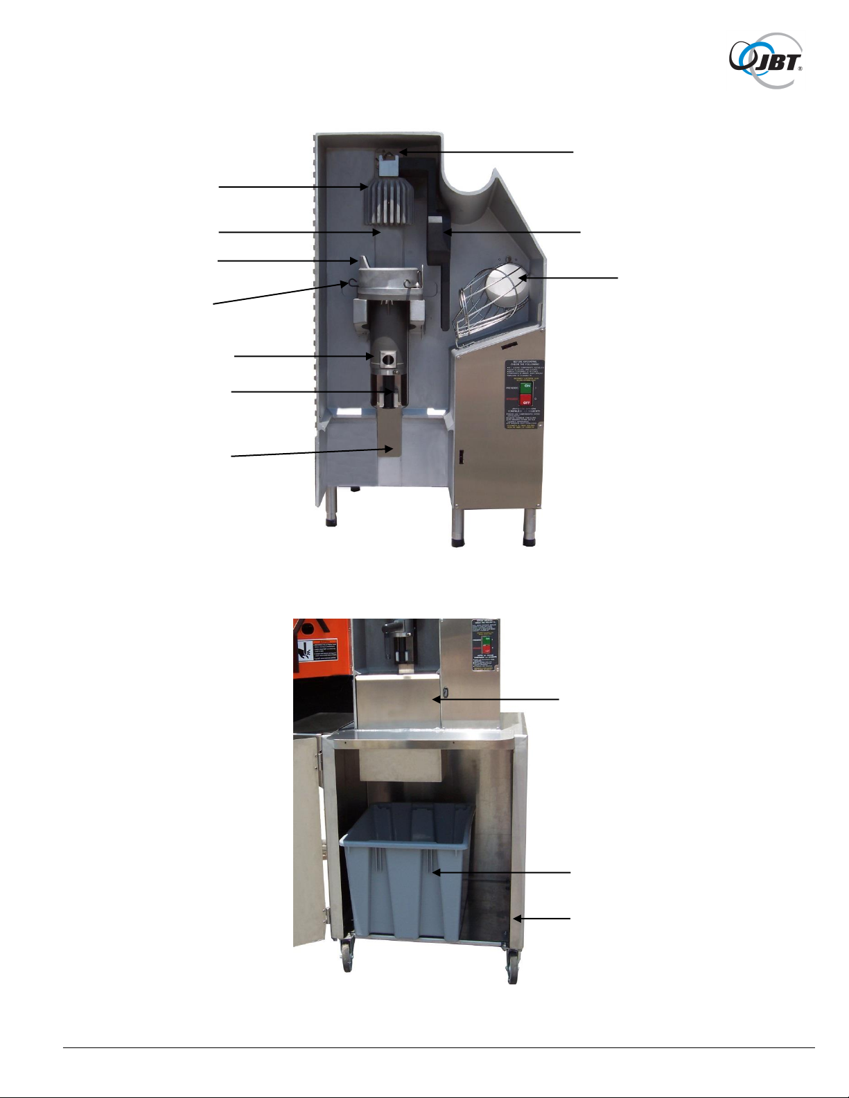
9 FNS-0006-060-EN November 2017 Rev F
Figure 1b. Juicing Components Assembly
Figure 1c. Optional Cart & Waste Container
Upper Cup
Spring
Fruit Lift
Upper Cup
Upper Splash
Guard
Lower Cup
Lower Cup
Spring
Lower Splash
Guard
Orifice Tube
Note: Groove
part of Orifice
Tube in slot.
Waste Chute
Waste Container
Cart

10 FNS-0006-060-EN November 2017 Rev F
Operating Instructions
Equipment Check
Before plugging the JBT Corporation Citrus Juicer into an electrical outlet, the
following steps must be performed:
1. Locate the Citrus Juicer on a level surface.
This will prevent fruit feed problems.
2. Check waste container.
Make sure that waste container is in place.
3. Check juicing components
Use key to unlock juicing components cover. Open cover and check that juicing
components are installed and securely fastened. See Figure 1b, page 9.
4. Close and lock access cover.
Juicing component cover must be locked. Counter top waste container (if used)
must be in place with key engaged. NEVER operate Citrus Juicer unless all covers
are in place.
5. Replace juice nozzle.
6. Make sure juice collector is in place.
7. Check the fruit feed chute or hopper for foreign objects.
Remove any foreign objects found in the chute or hopper.
8. Make sure floor area around Citrus Juicer is clean and free of obstructions and water.
When water is necessary, wear appropriate non-slip footwear.
11 FNS-0006-060-EN November 2017 Rev F
Operating Instructions
Juicing
CAUTION: DO NOT RUN THE CITRUS JUICER WITHOUT FRUIT FOR MORE
THAN ONE MINUTE; IT CAN RESULT IN EQUIPMENT DAMAGE.
CAUTION: READ AND UNDERSTAND THE SAFETY AND OPERATING
INSTRUCTIONS BEFORE OPERATING THE CITRUS JUICER.
1. Turn on Citrus Juicer.
Push the "ON-OFF" button to "ON" position.
2. Fruit may be fed into the Citrus Juicer one at a time (Single Feed) or in bulk,
using optional hopper.
a. Single Feed
DO NOT overload chute or fruit will accidentally be double fed. Fruit chute can be
loaded from the side with several fruit at a time, or can be fed one at a time through
hole in cover which is sized for max. fruit diameter.
b. Bulk Feed - Optional Hopper
Dump approx. 1/2 carton (20 Ibs.) of fruit into the hopper. Fruit may be divided
between the carton and carton lid for ease of lifting.
3. DO NOT use the single-feed chute when optional hopper is mounted on
machine.
4. Turn off Citrus Juicer.
Push the "ON-OFF" Switch to the "OFF" position.
5. Dispense juice.
Fresh juice will separate.
Stir before dispensing.
6. Clean Citrus Juicer.
If finished juicing, clean Citrus Juicer as soon as possible.
(See next page for cleaning instructions.)
12 FNS-0006-060-EN November 2017 Rev F
Cleaning Instructions
ALWAYS follow cleaning and maintenance schedules in this manual to prevent equipment
damage.
Clean Citrus Juicer as soon as possible after juicing. Use a soft towel or sponge to wipe equipment
parts. DO NOT use abrasive pads such as Scotch Brite®, steel wool, etc.
The recommended cleaner is JBT Corporation brand CorKlean. CorKlean is a low-foaming alkaline
equipment cleaner. It is safe on aluminum, 100% water soluble and free rinsing. CorKlean has been
especially formulated for cleaning food processing equipment. Follow instructions on cleaner label
for dilution.
2. Turn off Citrus Juicer with Juicing Component cups separated and Upper Arm in
highest possible position.
3. DISCONNECT ELECTRICAL PLUG.
3. If Citrus Juicer is on optional cart, pull Citrus Juicer to clean-up area, if one is
available.
4. Brush all loose peel into waste container or bag.
5. Empty and rinse waste container.
13 FNS-0006-060-EN November 2017 Rev F
Cleaning Instructions
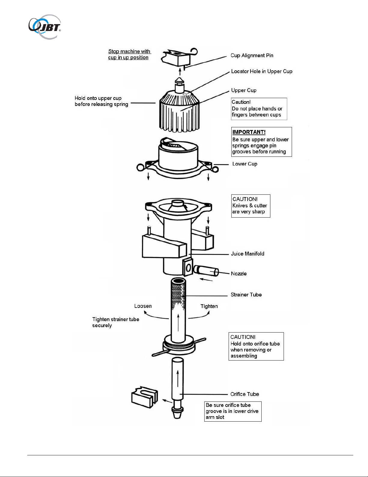
6. Remove juicing components.
a. Cups should be separated. (Citrus Juicer should be operated a couple
cycles just before disassembly and have been turned off with cups in the
separated position.)
b. Grasp upper cup and release by flexing spring. Place upper cup in soaking
container.
CAUTION: DO NOT PLACE HANDS OR FINGERS BETWEEN CUPS.
c. Remove lower cup by squeezing spring and lifting up.
Place lower cup in soaking container.
CAUTION: CUTTER AND KNIVES ARE SHARP.
d. Install red protective cap on cutter.
(Red protective cap is provided.)
e. Loosen strainer tube prior to removing manifold.
f. Grasp juice manifold and orifice tube firmly. Remove entire juicing
components assembly.
g. Grasp orifice tube and pull out of strainer tube. If orifice tube cannot be
removed, re-assemble to juicer, with lower cup in place, and operate a
couple of cycles.
g. Remove strainer tube from inside juice manifold by turning tube counter-
clockwise and sliding out.
Place juicing components into soaking container.
7. Prepare cleaning solution.
JBT Corporation brand CorKlean is recommended, see page 12. Read the
product label. Follow the manufacturer's mixing directions and safety
precautions.
8. Immerse all components in cleaning solution.
Prior to immersing use the blunt end of plastic rod provided to displace any fruit
material lodged in the bore of the orifice tube.
Use pointed end of plastic rod to displace any fruit material lodged in cup fingers.
14 FNS-0006-060-EN November 2017 Rev F
Figure 2. Juicing Components

15 FNS-0006-060-EN November 2017 Rev F
9. Scrub components.
Use a brush, towel, or sponge. DO NOT use abrasive pads such as Scotch Brite®,
steel wool, etc. Thoroughly rinse with clean water, then thoroughly rinse with
sanitizer solution. Follow the manufacturer's mixing directions and safety
precautions. As an alternate cleaning method, all juicing components can be put in
a dishwasher. If this method is used, components should be washed in CorKlean
at least once a week. DO NOT soak aluminum cups longer than 30 min. Then,
rinse and sanitize.
10. For best results, soak strainer tube in CorKlean overnight.
After soaking overnight, rinse the strainer tube thoroughly before using. Check that
all strainer tube holes are clean. Clean strainer tube with a hard spray from a hose
while moving orifice tube back and forth in strainer tube. Rinse thoroughly with
sanitizer solution. Allow to air dry.
11. If possible, hose down juicing area and cover.
If location prohibits using a hose to clean juicing area and cover, ensure waste
container is in place. Wash down the exposed juicing area and cover with a
sponge or spray applicator using the recommended cleaning solution. Cover may
be rinsed in place. Allow to stand for two minutes before rinsing thoroughly with
water.
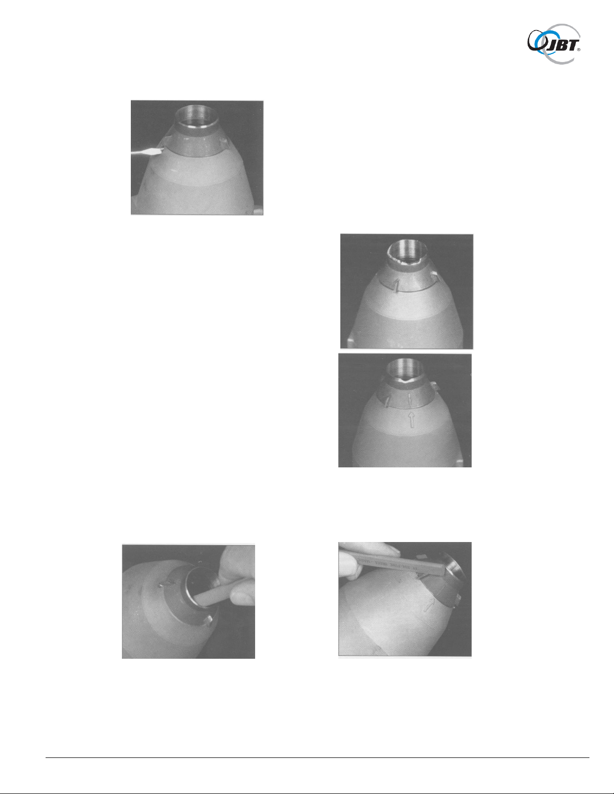
12. Re-assemble juicing components.
Start by re-assembling strainer tube into juice manifold, and tightening. Insert
orifice tube into bottom of strainer tube. Mount juice manifold assembly onto
locating pins with orifice tube notch engaging lower drive. Remove red protective
cap from cutter. Install lower cup and be sure spring snaps into pin grooves. Install
upper cup by slipping pin into stem hole, and turning until alignment pin
engages cup. Be sure spring engages.
13. CorKlean solution can also be used to remove smudges and finger marks from
aluminum exterior of Citrus Juicer. This should be done periodically to maintain the
exterior appearance of the machine.
14. Remove wax build-up as needed. (1 tablespoon of ammonia in 32 oz. spray bottle)
Cups, feed chute, and other parts may acquire a build-up of wax overtime.
a. Soak cups for five minutes in an ammonia cleaning solution. Rinse thoroughly
with sanitizer solution.
b. Wipe feed chute and other parts with a cloth soaked in ammonia cleaning
solution. Rinse thoroughly with sanitizer solution.
15. Remove orange discoloration as needed.
Equipment may exhibit some build-up or orange coloration over time. Wipe with a
cloth soaked in CorKlean solution. Rinse thoroughly with sanitizer solution.
16 FNS-0006-060-EN November 2017 Rev F
Maintenance
Before performing any maintenance, DISCONNECT ELECTRICAL PLUG.
After every juice run:
1. Check cutter and knives for sharpness.
CAUTION: CUTTER AND KNIVES ARE SHARP.
Refer to Figure 3 to determine condition of cutter.
If dull, sharpen with a whetstone.
Refer to Figure 4a. to sharpen cutter.
If cutter is severely damaged or rolled over, replace cutter.
a. Cutter removal:
Disassemble juicing components per Figure 2, page 14. Install red protective
cap provided onto cutter. After red protective cap is installed, remove cutter.
Handle cutter with care to avoid direct contact with sharp edge. Loosen set
screw under front knife (make sure screw is backed out far enough to clear
cutter). Cutter should lift out. If not, tap the cutter lightly from inside the juice
manifold with 1-1/4" dia. rod (hammer handle).
b. Cutter installation.
Align arrows on cutter and juice manifold to seat cutter. Make sure cutter is
fully seated. Tighten setscrew. DO NOT over tighten.
17 FNS-0006-060-EN November 2017 Rev F
Figure 4a. Sharpening Cutter Figure 4b. Sharpening knife
with Whetstone with Whetstone
Figure 3. Installation of good cutter
Figure 3a. Bad cutter- REPLACE cutter
Figure 3b. Cutter that can be sharpened
18 FNS-0006-060-EN November 2017 Rev F
Maintenance
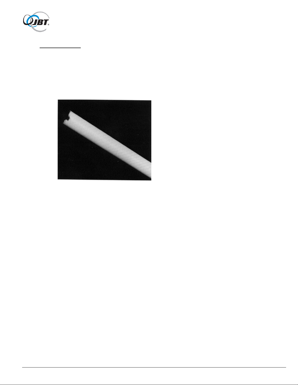
2. Check orifice tube for damage.
Refer to Figure 5.
Replace tube when:
a. Chunks are missing from top end.
b. Score marks 1/32" or deeper appear along the length of the tube.
Figure 5. Severely Damaged Orifice Tube
3. Check for loose or missing nuts and bolts.
a. Tighten or replace nuts and bolts as necessary.
b. DO NOT exceed torque ranges specified in Operator & Service Manual.
c. ALWAYS use JBT Corporation recommended spare parts.
19 FNS-0006-060-EN November 2017 Rev F
Periodic Inspection by Service Technician
Perform the following steps after every 3-4 months.
1. Test all interlock switches.
The Citrus Juicer should stop automatically when juicing cover is opened. If juicer is a
counter top model, Citrus Juicer should stop when waste container is pulled out. If Citrus
Juicer continues to run when either is opened, the interlock switch is defective.
Stop the Citrus Juicer and replace immediately.
See Troubleshooting Section.
2. Check all fasteners for tightness.
Remove back cover with spanner (snake eyes) security tool.
Check especially on the Sprockets, Crank Arms, Fruit Lift and Hopper.
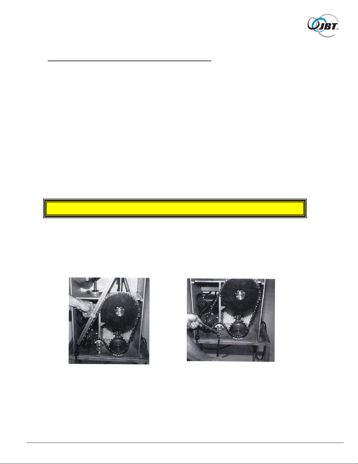
3. Check chain for tightness.
Refer to Figure 6a. and 6b.
Chain should have 1/4" maximum slack on top side. To adjust, loosen the two bolts
holding the chain take-up bracket to frame, pry bracket up to the correct adjustment.
CAUTION: DO NOT OVERTIGHTEN CHAIN.
4. Check chain and sprockets for rust.
If rust appears, coat chain and sprockets with a small amount of Teflon grease.
Figure 6a. Checking chain slack Figure 6b. Loosening bolts on chain take-up
bracket and prying up
20 FNS-0006-060-EN November 2017 Rev F
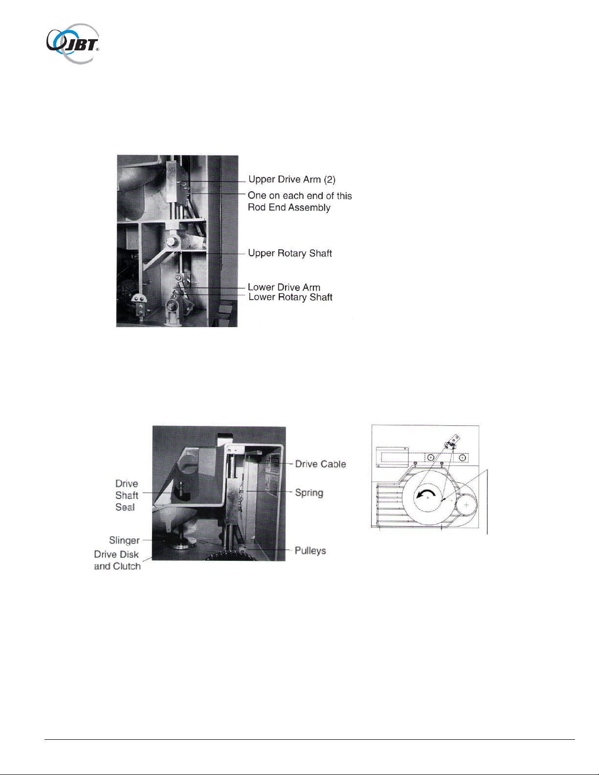
Adjust so that when arm is
at top of stroke, collar on cable engages slot
in disk at tangent point here. Hopper rotates
as shown on upstroke.
5. Grease Fittings
Refer to Figure 7.
Using a grease gun with a flexible hose, grease seven fittings with Super Lube®Teflon grease. Try
to force grease into thrust washer between crank arms/sprockets and the main frame.
Figure 7. Grease Fitting Locations
6. Check optional hopper shaft seal & slinger.
Refer to Figure 8a. and 8b.
Shaft seal prevents water from getting into back of Citrus Juicer, replace if defective.
Slinger prevents water from getting into one way clutch, replace if defective.
Figure 8a.
7. Check drive area for cleanliness.
If any peel and or water is in rear of Citrus Juicer, find and repair leak. If any of the splash
guards need replaced, see rebuilding section.
Top View Figure 8b.

21 FNS-0006-060-EN November 2017 Rev F
Troubleshooting-Operator
CAUTION: NEVER REACH INTO MOVING PARTS TO CLEAR A JAM,
NO MATTER HOW SIMPLE IT SEEMS.
Citrus Juicer will not start.
1. Citrus Juicer is not plugged into electrical outlet.
2. Building circuit breaker has tripped.
3. Juicing area door not closed. Optional counter top waste container not properly installed.
4. Citrus Juicer is jammed.
Call for service.
5. "ON-OFF" switch is defective.
Call for service.
6. One or more covers have a defective interlock switch.
Turn off Citrus Juicer. Call for service.
7. Overloaded circuit.
Citrus Juicer needs to be on separate (own) electrical outlet.
8. Low voltage to machine.
Use 110 volts minimum.
Citrus Juicer starts, but shuts off.
1. Building circuit breaker is not properly rated.
2. Extension cord or wiring is too long.
Shorten extension cord or use heavier gauge wire.
(See page 6, "Electrical Specifications")
3. All covers are not completely closed.
Close any open covers.
Citrus Juicer runs with covers open or off.
1. Turn off Citrus Juicer. Call for service.

22 FNS-0006-060-EN November 2017 Rev F
Troubleshooting-Operator
Citrus Juicer stalls trying to squeeze a fruit.
NOTE: Do not continue to process fruit if juicer is stalling more than once per case.
1. Fruit has part of stem on it.
Turn off Citrus Juicer. Remove fruit from Citrus Juicer and restart.
2. Peel is too thick.
Turn off Citrus Juicer. Remove fruit from Citrus Juicer and restart.
3. Cutter is damaged.
Sharpen or replace cutter as specified on page 17.
Citrus Juicer emits a "squealing" sound during operation.
1. Turn off Citrus Juicer. Call for service.
Low Juice Yield.
Excessive juice splattering during juicing operation.
1. Fruit is rotten or fruit stems are pulled.
Remove unsuitable fruit.
2. Orifice tube is damaged.
See page 18 to determine if it needs replacement.
3. Strainer tube is plugged.
Clean strainer tube. See page 15.

23 FNS-0006-060-EN November 2017 Rev F
Troubleshooting-Operator
Fruit is being chopped instead of juiced.
1. Fruit is too large for Citrus Juicer.
Turn off Citrus Juicer. Remove oversized fruit. Maximum diameter is 3-1/4".
2. Fruit feeder is sticky or unclean.
Turn off Citrus Juicer. Remove fruit.
Clean fruit lift.
3. Citrus Juicer not level. Locate Citrus Juicer on level surface.
Fruit is fed two at a time.
1. Fruit is too small for Citrus Juicer.
Turn off Citrus Juicer. Remove undersized fruit. Minimum diameter is 2-1/2".
Fruit is not fed during every cycle.
1. The optional hopper mechanism is designed to put fruit into a single file and to break-up bridging
before feeding. When hopper is full, it sometimes takes a couple of cycles to begin feeding.
Large or out of round fruit sometimes do not feed well.
Cutter is constantly being damaged.
1. Red protective cap is not being placed on cutter prior to removing juice manifold and during
handling.
2. Juice manifold is not secure.
Be sure spring hold-downs on lower cup are properly engaged.

24 FNS-0006-060-EN November 2017 Rev F
Troubleshooting-Service
Citrus Juicer will not start.
1. Citrus Juicer is not plugged into electrical outlet.
2. Building circuit breaker has tripped.
3. Juicing area door not closed and locked.
4. Optional waste container not in place or pushed all the way in.
5. Buzzing sound comes from on/off switch.
Juicer needs to be on a separate (its own) electrical circuit with a minimum of 100 volts
supply.
6. On/Off switch holds in the "On" position with a humming noise coming from motor.
Capacitor needs replaced. It is located in motor junction box.
7. Defective interlock switch or on/off switch.
a. Remove the front cover protecting electrical box and motor. Remove electrical
box cover with on-off switch.
Refer to Figure 9.
Figure 9. Electrical Box
b. Check continuity across each switch.
Refer to Figure 10a. and 10b.
Using a meter, check each switch individually. Check by opening and closing door
cover & optional waste container. Replace defective switches.
8. Defective on/off switch or motor.
Replace on/off switch first. (Make sure interlock switches are operating properly). If
this does not solve problem replace entire gear motor.

25 FNS-0006-060-EN November 2017 Rev F
Figure 10a.
Figure 10b.

26 FNS-0006-060-EN November 2017 Rev F
Troubleshooting-Service
Citrus Juicer emits a "squealing" sound during operation.
1. Rod end, rotary, or linear bearings need lubrication. See Periodic Inspection item 5, page 20.
2. Rod end, rotary, or linear bearings need replaced. See rebuilding.
Hopper disk does not rotate.
Note that disk operates in intermittent motion and only rotates on the up stroke of juicer.
1. Drive cable has come off one of the pulleys.
Refer to Figure 8a., 8b. on page 20.
a. Remove back cover. Use spanner (snake eyes) security tool to loosen captive
screws.
b. Drive cable should be adjusted with light spring tension. Make sure drive cable is
wrapped per Figure 8a, 8b, and adjust if necessary.
2. Drive clutch is worn.
Replace clutch by loosening set collar on drive shaft, unhooking drive cable and lifting
shaft out of drive disk. Press new clutch into drive disk making sure disk is driven in
counter-clockwise direction. (Rotates on the up stroke of the juicer).
Hopper disk rotates in both directions.
1. Clutch is rusted or frozen.
Refer to figure 8.
Pry up slinger and spray with a lubricant, rotate by hand to loosen. If still frozen, replace
as described under “drive clutch is worn”. After replacing, make sure slinger is
lubricated with a light coat of grease and pressed all the way down on drive disk.

27 FNS-0006-060-EN November 2017 Rev F
Rebuilding
It is best to replace all bearings at the same time.
Step-by-Step instructions for replacing all bearings and rod ends.
1. Remove all juicing components.
Refer to Figure 2, page 14.
2. Remove fruit lift.
Remove 1/4-20 x 3" hex head cap screws.
3. Remove splash guards in juicing area.
Refer to Figure 11.
Use knife to cut away Silicone from plastic splash guards and drive arms. If necessary,
use hand crank adapter on motor sprocket with 1/2" drive ratchet to rotate Citrus Juicer
into position to pull off splash guards. Remove upper cup spring, upper splash guard.
Remove clip that holds lower splash guard in place.
4. Remove back cover
Use spanner (snake eyes) security tool to loosen captive screws.
Refer to figure 12.

28 FNS-0006-060-EN November 2017 Rev F
Figure 11. Front View of Citrus Juicer
Figure 12. Back View of Citrus Juicer
Upper Drive
Splash Guard
Center Splash
Guard
Lower Drive
Splash Guard

29 FNS-0006-060-EN November 2017 Rev F
Rebuilding
5. Rotate drive so upper cup drive is in the down position.
Remove chain, spring clip type master link.
Be careful - drive arms may move as chain is removed.
Remove large sprocket. Use a 9/16” socket and a 3/16" Allen wrench.
6. From the back use a 9/16" wrench or socket to loosen hex
head cap screw on crank arm for upper cup drive.
NOTE: If just replacing rod ends on upper cup drive assembly, use
access hole under center splash guard to remove left hand cap
screw from crank arm.
Use a 3/16" Allen wrench to loosen set screw on keyway. Back
screws out at least 1/4" to clear flats on shafts.
Refer to Figure 13.
From the back repeat above steps on crank arm for lower drive.
Refer to Figure 14.
7. Remove lower drive sprocket with shaft still connected.
Remove upper drive shaft.
Refer to Figure 15.
Figure 13. Using Socket to Loosen Upper Cup Crank Arm

30 FNS-0006-060-EN November 2017 Rev F
Figure 14. Loosening Lower Crank Arm
Figure 15. Sprocket with Shaft being Removed

31 FNS-0006-060-EN November 2017 Rev F
Rebuilding
8. Remove linear shafts.
With a 3/16" Allen wrench, loosen setscrews at top and bottom of
all three shafts. Back screws out at least 1/4" to clear flats on
shafts. If shafts are stuck, use bearing removal puller with 3/8"16 x 2" hex head cap screw to break free shafts. NOTE: Lower
shaft comes out of bottom of Citrus Juicer.
Refer to figure 16.
9. Lift out upper and lower drive arms with linkages still attached.
10. Disassemble rod end assemblies from drive and crank arms.
Note location and numbers of washers and spacers.
NOTE: Screws and rod ends on both crank arms are left-hand threads.
11. Disassemble rod ends from links.
Re-assemble with new rod ends (Refer to Figures 17 and 18), using rod end adjustment bar
with the appropriate rod and tooling washer. Remember one end is a left-handed thread.
Wrenches required are 3/4", 7/8" and 15/16".
Figure 16. Removal of Linear Shafts with Puller

32 FNS-0006-060-EN November 2017 Rev F
Figure 17. Assembly of 5/8" Rod Ends
Figure 18. Assembly of 1/2" Rod Ends

33 FNS-0006-060-EN November 2017 Rev F
Rebuilding
12. Remove sleeve bearings from upper and lower drive arms.
Refer to figures 19a., 19b. and 20.
Bearings can be pulled out using puller, 1" removal slug, and short threaded removal rod;
or can be driven or pressed out using driver. New bearings can be installed by
compression (Figure 21) by using installation pilot, installation washer and long threaded
installation rod, or just use installation pilot and press bearings into place. Light coat of
Teflon grease can be used on O.D. of bearings to aid in installation.
Figure 19a. Remove Bearings from Upper Drive Arm
Figure 19b.

34 FNS-0006-060-EN November 2017 Rev F
Figure 20. Removing Bearings from Lower Drive Arm
Figure 21. Installation of Bearings into Drive Arms

35 FNS-0006-060-EN November 2017 Rev F
Rebuilding
13. Re-assemble rod end assemblies to drive arms, again making sure left-hand
threaded ends are on the crank arms.
Refer to Figures 22 and 23.
Use Loctite #242 on all fasteners. Tighten to torques as shown. Make sure rod end lock
spacer is installed on rod end in upper drive arm. Make sure plastic bearing buttons are
installed on each side of lower drive arm.
Figure 22. Completed Assembly of Upper Cup Drive Arm

36 FNS-0006-060-EN November 2017 Rev F
Figure 23. Completed Assembly of Lower Drive Arm

37 FNS-0006-060-EN November 2017 Rev F
Rebuilding
14. Remove sleeve bearings from main frame.
Refer to Figures 24 and 25.
The outer upper drive shaft bearing can be removed using puller,
1-1/4" removal slug, and short threaded removal rod. The inner bearing can be removed the
same way, or can be pressed out using driver. The lower shaft bearings can be removed the
same way except using 1" removal slug. New bearings can be installed by compression
(Figure 26) by using installation pilot, installation washer, and long threaded installation rod.
Light coat of Teflon grease can be used on O.D. of bearings to aid in installation.
15. There are thrust washers next to each bearing on the main frame. Make sure the old
ones have been removed and new ones installed.
One side of thrust washer is plain metal. Silicone this side and glue them to the frames (Typical 4
places).
DO NOT get silicone on surface of any bearing.
16. Before re-assembling, check all shafts for excessive wear;
replace as necessary.
Re-assemble parts in the reverse order of removal. DO NOT forget to put keys back into crank
arms.
Tighten fasteners to torques shown.
Figure 24. Removing Bearing from Lower Rotary Drive

38 FNS-0006-060-EN November 2017 Rev F
Figure 25.
Removing Bearings
from Upper Rotary Drive
Figure 26. Installation of Bearings and Thrust Washers

39 FNS-0006-060-EN November 2017 Rev F
Rebuilding
17. Before installing chain, align timing marks as shown.
Refer to figure 27.
This is critical to operation of the machine. Adjust chain as shown in Periodic Inspection
section.
18. To check to see if upper cup crank rod end link needs to be adjusted, install juice
manifold, upper and lower cup.
Refer to Figure 28.
Using hand crank adapter, gently rotate until upper cup drive is in the full down position.
DO NOT force it, if it appears to be binding, readjust rod end link. If it rotates freely past
bottom position, check for too much clearance. In the full down position, release spring
on upper cup. Cup should not drop down; if it does, readjust rod end link.
Cups should just meet – no clearance – no bind.
Figure 27. Align Timing Marks

40 FNS-0006-060-EN November 2017 Rev F
Figure 28. Checking for Cup Clearance

41 FNS-0006-060-EN November 2017 Rev F
Rebuilding
19. Remove juicing components and install the upper drive splash guard (groove goes down and
in) and upper cup spring onto drive arm.
Refer to Figure 29.
Figure 29. Installation of
Upper Splash Guards
20. Install lower splash guard.
Be sure "up" stamped on part faces up, and guard is flat against
wall. Seal with RTV.737 silicone, and install clip.
Refer to Figure 30a.
21. Install Center Splash Guard
Chamfer goes up and to the left. Rotate Citrus Juicer with hand crank to make sure all splash
guards are operating properly.
Figure 30a. Installing Figure 30b. Installing
Lower Splash Guards Center Splash Guard.

Item
Part Number
Description
1
060-00180-B
Tool, FNS, Bearing Pilot Install
2
060-00181-B
Tool, FNS, Bearing Washer Install
3
060-00182-B
Tool, FNS, Bearing Puller
4
060-00183-B
Tool, FNS, Bearing Slug 1"
5
060-00184-B
Tool, FNS, Bearing Slug 1-1/4"
6
060-00185-B
Tool, FNS, Bearing Driver Remove
7
060-00186-B
Tool, FNS, Rod, Bearing Install
8
060-00187-B
Tool, FNS, Rod, Bearing Removal
9
060-00188-B
Tool, FNS, Washer, Rod End 1/2"
10
060-00189-B
Tool, FNS, Washer, Rod End 5/8"
11
060-00190-B
Tool, FNS, Bar, Rod End Adjust
12
060-00191-B
Tool, MFJ, Adapter, Hand Crank
12a
060-02120-B
Tool, CJ, Adaptor, Hand Crank
13
004-350-648
Screw, MFJ, Cap, Hex, 5/8-11 x 1-1/2" Lg
14
004-350-571
Screw, MFJ, Cap, Hex, Full Thread
15
004-110-063
Nut, MFJ, Hex, 1/2-13, Grade 8 Steel
16
004-815-100
Washer, Plain Narrow,1/2"
17
004-815-080
Washer, MFJ, Plain Narrow, 3/8", C/G
18
004-350-407
Screw , MFJ, Cap, Hex, 3/8"-16 x 2" Lg, C/G
20
009-998-004
Bit, Spanner Insert, #8 1/4" hex
Rebuild Tooling Kit 060-00202
42 FNS-0006-060-EN November 2017 Rev F

43 FNS-0006-060-EN November 2017 Rev F
Figure 31. Rebuild Kit

Item
Part Number
Qty
Description
1
060-02007-R
1
Main Frame Machining
2
005-576-061
1
Key, Sq, 1/4" x 3/4" Lg
3
005-576-242
1
Key, Sq, 1/4" x 1" Lg
4
007-120-205
5
Fitting, Grease 1/4-28 x 45°
5
060-02043
1
Pin, Cup Locator
6
005-576-223
1
Key, Sq, 3/16" x 1", SS
7
060-02016
1
Arm, Drive , Upper Cup (Includes (4) item 45 & (2) Item 4)
8
004-352-661
1
Screw, Cap, Hex, 5/8-11 x 2-1/2" Lg, SS
9
060-00057
1
Rod End Lock
10
060-02060
1
Rod End, Upper Assembly
11
004-816-120
4
Washer, Plain, 5/8, Narrow, SS
12
060-00078
1
Screw, L. H.
13
060-02027
1
Crank, Upper Cup Drive, 5-5/8" Lg.
14
005-098-113
2
Washer, Thrust
15
060-02014
1
Arm, Drive, Orifice Tube (Includes (2) item 45 & (1) Item 4)
16
060-00068
2
Bearing, Plastic
17
060-02046
1
Sprocket, 50B48, 1-1/4 Bore
18
060-02017
2
Shaft, Upper Linear
19
004-352-571
1
Screw, Cap Hex, 1/2-13 x 1-1/2" Lg, SS
20
060-00062
1
Rotary Main Drive Shaft
21
060-02061
1
Rod End, Lower Assy. (Includes Items 21a through 21c)
22
005-576-249
1
Key, Sq, 1/4" x 1-1/2" Lg, SS
23
004-352-572
1
Screw, Cap Hex, 1/2-13 L.H. x 1-1/2" Lg, SS
24
004-816-100
2
Washer, Plain, 1/2, Narrow, SS
25
060-02015
1
Shaft, Lower Linear
26
005-098-112
2
Washer, Thrust
27
060-02047
1
Sprocket, 50B24, 1BKWSS
28
005-576-246
1
Key, Sq, 1/4" x 1-1/4" Lg, SS
29
060-00061
1
Shaft, Rotary Orifice Drive, 4-7/8" Lg
30
004-350-212
1
Screw, Cap Hex, 3/8-16 x 1-3/4" Lg, Grade 8, S/L
31
004-352-327
4
Screw, Cap Hex, 5/16-18 x 1-1/2" Lg, SS
34
060-02005
1
Electrical Subassembly
35
005-245-024
1
Chain, #50 x 50-5/8 Lg. (81 Links) W/ Half Link & Master Link
36
004-816-070
8
Washer, Plain, 5/16", Narrow, SS
37
005-804-216
1
Sprocket, 50B15, 3/4BKWSS, 13 Strokes/Minute
37
005-804-063
1
Sprocket, 50B14, 3/4BKWSS, 10 Strokes/Minute (220V/50 Hz Only)
38
004-111-040
4
Nut, 5/16-18, SS
41
004-541-138
11
Screw, Set Socket, Cup Point, 3/8-16 x 3/4" Lg, S/L, SS
42
060-02026
1
Orifice Tube Crank
44
004-450-050
2
Screw, Set Socket, 1/4-20 x 1-1/2" Lg, S/L, 18-8
45
060-10192
1
Chain Tensioner Assembly
46
060-10193
1
Chain Guide
47
060-10170
1
Chain Tensioner Bracket
48
004-401-073
4
Screw, Truss Head, 1/4-20 x 1" Lg, SS
49
004-356-088
2
Screw, Cap, Socket, 5/16-18 x 1" Lg, SS
50
004-352-241
2
Screw, Cap, Hex Head, 1/4-20 x 1" Lg, SS
51
004-116-015
2
Nut, Hex, Jam, 1/4-20, SS
Drive Parts 060-02002
44 FNS-0006-060-EN November 2017 Rev F

45 FNS-0006-060-EN November 2017 Rev F
Figure 32. Drive Parts

Item
Part Number
Qty
Description
1
060-02003
1
Cover Assembly (See Page 58 for Detail)
2
060-02022
1
Tube, Strainer, CJ, 0.033
2
060-02088
1
Tube, Strainer, CJ, 0.040
2
060-02089
1
Tube, Strainer, CJ, 0.055
3
060-02034
1
Nozzle, Short, 4-3/4" Lg
3
060-02130
1
Nozzle, Long, 8-3/4" Lg
3
060-02310
1
Nozzle, Straight (CFA)
4
060-02038
1
Tube, Orifice, CJ
5
060-00225
1
Cutter & Knives, MFJ & CJ
6
060-02062
1
Cup Assembly, Upper (Includes Item 6a)
6a
060-02020
1
Pin, Upper Cup
7
060-02063
1
Cup Assembly, Lower (Consists of Items 7a, 7b and 7c)
7a
060-02031
1
Spring, Cup, Lower
7b
060-02009
1
Cup, Lower
7c
004-380-014
2
Screw, Fillester Head, 10-24 x 5/16" Lg slotted, SS
8
06-002013
1
Manifold, Juice
14
004-406-003
1
Screw, Mach Round Head, # 4-40 x 3/16" Lg, SS
15
009-092-018
1
Cap, Cover (Not Shown)
16
007-132-143
1
Down Spout Nozzle
18
007-486-132
1
O-Ring, Nozzle, CJ
Options
21
060-02231
1
Waste Container Assembly Without Legs (See Pages 64-65)
6-1/2" Deep Waste Container
21
060-02231-01
1
Waste Container Assembly With Legs (See Pages 64-65)
10-1/2" Deep Waste Container
060-02094
1
Thru The Counter Assembly (Not Shown)
060-02134
1
Cart Assembly, Enclosed (Not Shown)
060-02092
1
Hopper Assembly (Not Shown)
060-02333
1
Tube, Replacement, 3ft (Not Shown)
(Use only with Item 3, 060-0231, Straight Nozzle)
Juicing Parts 060-02000
46 FNS-0006-060-EN November 2017 Rev F

47 FNS-0006-060-EN November 2017 Rev F
Figure 33. Juicing Parts

Item
Part Number
Qty
Description
1
060-02117
1
Cart Frame
2
060-02053
1
Chute, Waste, Counter Top Models
3
004-401-022
6
Screw, Mach Truss, #10-24 x 3/8" Lg, SS
4
060-02132
1
Shelf
5
060-02133
1
Cart Floor
6
060-02123
1
Cart Door
7
009-080-536
2
Caster, Swivel
8
004-352-315
20
Screw, Cap Hex, 5/16-18 x 3/4" Lg, SS
9
004-816-070
20
Washer, Plain, 5/16, SS
10
004-111-040
16
Nut, Hex, 5/16-18, SS
11
009-080-535
2
Caster, Rigid
12
009-609-041
1
Plug, Brake Hole (Dust Cover)
13
004-260-017
2
Rivet, Pop, 1/8" x 1/8" Lg, SS
14
009-425-019
1
Latch, Spring
15
060-00072
2
Hinge, Female
16
060-00071
2
Hinge, Male
17
004-260-015
4
Rivet, Pop, 3/16" x 1/4" Lg, SS
18
009-092-026
1
Waste Container
19
004-111-022
8
Nut Hex, #10-24, SS
20
060-02237
1
Decal, Cleaning Instructions
21
060-00122
1
Label, Moving Juicer (Not Shown)
22
060-00175
1
Label, Moving Juicer, Spanish (Not Shown)
23
004-461-025
4
Hook, #10-24, SS
24
004-385-030
4
Screw, Fillester Head, #8-32 x 1/2" Lg, SS
25
004-111-018
4
Nut, Hex, #8-32, SS
26
003-435-020
1
Edge, Trim, Neoprene Rubber, 3/16" Opening
Jet Spray / Chiller Dispenser
Item
Part Number
Qty
Description
060-02056
1
Dispenser, Chiller Assy (Not Shown)
060-02057
1
Shelf, Chiller Dispenser Unit (Not Shown)
009-120011
1
Lid, Single Walled, Chiller Dispenser (Not Shown)
060-02265
1
Lid, Jet Spray with Tapped Hole (Not Shown)
007-132-130
1
Fitting, Hose Adapter, , 1/2" x 3/4", Plastic (Not Shown)
003-925-090
1
Tubing, 5/8" OD x 1/2" ID, Clear Vinyl (Not Shown)
007-132-133
1
Elbow, Tube, Plastic, 1/2" x 3/4", White Nylon (Not Shown)
Cart Assembly Enclosed Parts 060-2134
48 FNS-0006-060-EN November 2017 Rev F

49 FNS-0006-060-EN November 2017 Rev F
Figure 34. Cart Assembly, Enclosed

110 Volt Citrus Juicer
Item
Part Number
Qty
Description
1
060-02065
1
Holder, Cord Grip
2
060-02064
1
Motor Assembly, 110V/60 Hz (prior to 8/2013)
2
060-02266
1
Motor Assembly, 110V/60 Hz (after 8/2013)
(for Motor Replacement, see below)
3
060-02041
1
Electrical Box Assembly
4
060-00096-09
1
Wire, Jumper, 16 Ga, 2" Lg (Not Shown)
5
007-143-395
1
Connector, Male, M20 x 1-1/2" Thread
6
006-220-046
1
Terminal, #10 Ring End, 10-12 Ga, Double Crimp Type
7
006-200-267
1
Switch, Safety, Schmersal
8
006-080-073
2 Ft
Cord, 14 Ga, 2 Conductor
9
006-080-071
1
Power Cord With 15A Plug, 10" Lg
10
006-060-075
1
Connector, Cord, 1/2" NPT, Straight, Flex
11
004-816-070
4
Washer, Plain, 5/16", SS
12
004-401-026
6
Screw, Mach Truss #10-24 x 5/8" Lg, SS
13
004-397-077
2
Screw, Mach Rd Slotted, #8-32 x 1/2" Lg, 304SS
14
004-352-327
4
Screw, Cap Hex, 5/16-18 x 1-1/2" Lg, SS
15
004-156-063
4
Nut, Hex, S/L, LT, 5/16-18, SS
Citrus Juicers with Waste Container Assembly
Item
Part Number
Qty
Description
16
060-02085
1
Bracket, Safety Switch
17
007-143-396
1
Fitting, Liquid Tight, Straight Strain Relief
18
007-143-395
1
Connector, Male, M20 x 1-1/2" Thread
19
006-200-268
1
Key, Safety, for 006200267 Schmersal
20
006-200-267
1
Switch, Safety, Schmersal
21
004-401-024
2
Screw Mach Truss #10-24 x 1/2" Lg, SS
22
004-401-022
2
Screw Mach Truss #10-24 x 3/8" Lg, SS
23
004-385-028
2
Screw, Mach FL, Security Type, #8-32 x 3/9" Lg, SS
21
006-080-073
1
Cord, 14 Ga, 2 Conductor x 1-1/2 Ft
Motor Replacement
For units with 060-02064 (prior to 8/2013), replacement of the motor requires a conversion kit
which includes the motor, conversion plate and associated hardware:
Item
Part Number
Qty
Description
060-10157
1
Sumitomo to Nord Conversion Kit (See Page 52)
Units with 060-02266 (after 8/2013) are equipped with a multi-bolt pattern plate. Motor can be
replaced without the need of the conversion kit:
Item
Part Number
Qty
Description
2
060-02266
1
Motor Assembly, 110V/60 Hz
Electrical Parts (110 Volt), 060-02005
50 FNS-0006-060-EN November 2017 Rev F

51 FNS-0006-060-EN November 2017 Rev F
Figure 35. Electrical Parts (110 V)

Item
Part Number
Qty
Description
1
060-10156
1
Adapter, Sumitomo to Nord Motor Conversion Plate
2
060-02266
1
Motor Assembly, CJ, 110V/60Hz, Nord, Mfg Use
3
004-816-072
6
Washer, Plain, 5/16", SS
4
004-806-060
4
Washer, Lock Reg, 5/16", SS
5
004-356-160
4
Screw, Cap, Socket, 5/16-18 X 1-1/4" LG,
Fully Threaded, Low Profile, SS
6
004-352-321
4
Screw, Cap Hex, 5/16-18 X 1" LG, SS
7
004-156-063
2
Nut, Hex, S/L, 5/16-18 (Light), SS
Sumitomo to Nord Motor Conversion Kit (110 Volt), 060-10157
52 FNS-0006-060-EN November 2017 Rev F

53 FNS-0006-060-EN November 2017 Rev F
Figure 36. Sumitomo to Nord Motor Conversion Kit

220 Volt Citrus Juicer
Item
Part Number
Qty
Description
1
004-401-026
6
Screw, Mach Truss #10-24 x 5/8" Lg, SS
2
006-220-046
1
Terminal, #10 Ring End, 10-12 Ga, Double Crimp Type
3
006-200-267
1
Switch, Safety, Schmersal
4
060-02041-01
1
Electrical Box Assembly, 220V
5
060-02064-01
1
Motor Assembly, 220V, 50/60 Hz (prior to 8/2013)
(Motor is 50/60Hz (same motor); Wire must be changed for
voltage over 115V)
5
060-02317
1
Motor Assembly, 220V, 50 Hz (after 8/2013)
5
060-02316
1
Motor Assembly, 220V, 60 Hz (after 8/2013)
(for Motor Replacement, see below)
6
007-143-395
2
Connector, Male, M20 x 1-1/2 Thread
7
060-00012
1
Power Cord
8
004-397-077
2
Screw, Mach Rd Slotted, #8-32 x 1/2" Lg, 304SS
9
006-080-073
4 Ft
Cord, 14 Ga, 2 Conductor (2 Pieces x 2 Ft)
Citrus Juicers with Waste Container Assembly
Item
Part Number
Qty
Description
10
060-02085
1
Bracket, Safety Switch
11
007-143-396
1
Fitting, Liquid Tight, Straight Strain Relief
12
007-143-395
1
Connector, Male, M20 x 1-1/2" Thread
13
006-200-268
1
Key, Safety, for 006200267 Schmersal
14
006-200-267
1
Switch, Safety, Schmersal
15
004-401-024
2
Screw Mach Truss #10-24 x 1/2" Lg, SS
16
004-401-022
2
Screw Mach Truss #10-24 x 3/8" Lg, SS
17
004-385-028
2
Screw, Mach FL, Security Type, #8-32 x 3/8" Lg, SS
18
006-080-073
1
Cord, 14 Ga, 2 Conductor x 1-1/2 Ft
Motor Replacement
For units with 060-02064-01 (prior to 8/2013), replacement motor must be same type, due to
mounting bolt pattern:
Item
Part Number
Qty
Description
5
060-02064-01
1
Motor Assembly, 220V, 50/60Hz
Units with 060-02317 (after 8/2013) are equipped with a multi-bolt pattern and have the option
of using either motor 060-02064-01 or 060-02317:
Item
Part Number
Qty
Description
5
060-02064-01
1
Motor Assembly, 220V, 50/60 Hz
5
060-02317
1
Motor Assembly, 220V, 50 Hz
Units with 060-02316 (after 8/2013) are equipped with a multi-bolt pattern and have the option
of using either motor 060-02064-01 or 060-02316:
Item
Part Number
Qty
Description
5
060-02064-01
1
Motor Assembly, 220V, 50/60 Hz
5
060-02316
1
Motor Assembly, 220V, 60 Hz
Electrical Parts (220 Volt), 060-02005-01 (50 Hz), 060-02005-02 (60 Hz)
54 FNS-0006-060-EN November 2017 Rev F

55 FNS-0006-060-EN November 2017 Rev F
Figure 36. Electrical Parts (220V)

110 Volt Citrus Juicer
Item
Part Number
Qty
Description
1
060-02039
1
Box, Electrical
2
006-060-078
1
Connector, Cord, 1/4 NPT for 3/16, #056-14-1002
3
007-143-386
2
Connector, 1/2", #S2112
4
006-221-079
1
Terminal, Block
5
006-200-511
1
Switch, On/Off
6
009-235-073
1
Gasket, Weber #AZZ63 Weber
7
004-397-018
2
Screw Mach, Round, #4-40 x 1" Lg, SS
8
004-440-011
2
Screw, Tap, Pan "F" Head 6-32 x 1/2" Lg
9
060-05064
2
Spacer, Terminal Block
10
007-143-388
3
Ring, Thd-Seal, 1/2", #52005740
11
007-143-387
2
Nut, Locking, 1/2", PVC, #LT9LD
12
060-00096-08
1
Wire, 16 Ga, Black, 10" Lg
13
006-221-084
2
Terminal, Fem Insul, Wire 22-18
14
009-455-002
A/R
Marker, Pins, Phoenix #BNB:1-6
15
004-440-010
2
Screw, Tap, "F", #4-40 x 3/8" Lg, SS
16
006-221-082
1
Terminal, Fem Insul, Wire 16-14
17
060-02040
1
Bracket, Electrical Box
18
004-401-022
4
Screw Mach Truss Head, 10-24 x 3/8" Lg, SS
19
006-090-209
1
Seal, Hole, Conduit 1/2, Hoffman AS050
20
060-00096-07
2
Wire, 20 Ga, White, 10" Lg
21
007-143-396
1
Connector, Sol Flex
22
009-450-057
1
Label, Caution, Electrical Hazard
220 Volt Citrus Juicer
Item
Part Number
Qty
Description
3
007-143-386
2
Connector, 1/2", #S2112
5
006-200-266
1
Switch, On/Off, Weber AHWTS070Z3
10
007-143-388
4
Ring, Thd-Seal, 1/2", #52005740
11
007-143-387
2
Nut, Locking, 1/2", PVC, #LT9LD
12
060-00096-08
2
Wire, 16 Ga, Black, 10" Lg
16
006-221-082
2
Terminal, Fem Insul, Wire 16-14
21
007-143-396
2
Connector, Sol Flex
Electrical Box Assembly 060-02041
56 FNS-0006-060-EN November 2017 Rev F

57 FNS-0006-060-EN November 2017 Rev F
Figure 36. Electrical Box
22

Item
Part Number
Qty
Description
2
060-02019
1
Fruit Guide
3
060-02152
1
Guard, Splash, Lower, SS
4
060-02032
1
Spring, Cup, Upper
8
060-02150
1
Guard, Splash, Center
9
004-392-193
2
Screw, Machine, Pan Head, #6-32 x 7/8" Lg, SS
10
060-02151
1
Guide, Center
12
060-02279
1
Guard, Splash, Upper, SS
13
060-02045
1
Fruit Guide, Wire Frame
14
060-02240
1
Front Door Assembly
15
060-02165
1
Fruit Lift, Plastic (after 6/2016)
060-02023
1
Fruit Lift (before 6/16, field service use only after 6/2016)
16
060-02066
1
Cover, Back
17
060-02028
1
Guard, Wire Finger
18
060-02033
1
Cover, Electrical Access
19
060-02018
2
Pin, Lower Cup
20
004-440-011
2
Screw, Tap, Pan "F" Head, #6-32 x 1/2" Lg
21
004-397-129
2
Screw, Mach Rd, 10-24 x 1/4" Lg, SS
22
004-401-024
4
Screw, Mach Truss,#10-24 x 1/2" Lg, SS
23
004-352-260
2
Screw, Cap Hex, 1/4-20 x 2-1/2" Lg, SS
23a
004-352-267
2
Screw, Cap Hex, 1/4-20 x 3", SS
24
004-385-053
2
Screw, Mach FL S/L, 8-32 x 3/8" Lg, SS (Hinge To Frame)
25
060-02067
1
Latch, Door
27
015-03937
1
Patent Plate
28
015-03935
1
Name Plate
29
060-00120
2
Sign, Warning, Covers, Single Head
30
060-00176
2
Label, Warning, Cover, Spanish
31
004-260-017
8
Rivet, Pop, 1/8" x 1/8" Lg, SS
32
060-02069
1
Label, Off/On
33
060-02070
1
Clip, Lower Splash Guard
34
004-401-022
1
Screw, Mach Truss, 10-24 x 3/8" Lg, SS
35
060-02139
11
Screw, Captive Panel, Pan Head, #8-32 x 1/2" Lg, SS
36
004-816-060
2
Washer, Plain, 1/4, Narrow, SS
37
060-02077
1
Gasket, Electrical Access Cover
38
004-385-023
6
Screw, Mach Flat Head, 8-32 x 1/4" Lg, SS
39
004-380-014
1
Screw, Fillester Head, #10-24 x 5/16" Lg, SS
40
060-02128
1
Cover, Straight Side
41
060-02129
1
Cover, Hopper Side
42
003-810-007
20 Ft
Tape, Double Sided, 3/4 Wide x 25 Mils Thick
44
006-090-256
2
Plug, Hole, 1/4
45
060-02087
1
Safety Key
46
060-02059
2
Button, Door
47
004-385-028
2
Screw, Mach Flat, S/L, 8-32 x 3/8" Lg, SS
48
060-00104
1
Decal, Warning, English/Spanish (on side of item 41)
Citrus Juicers with Solid Fruit Guide
Item
Part Number
Qty
Description
49
060-02274
1
Weldment, Upper Fruit Guide
50
060-02192
1
Fruit Guide Mount, Lower
51
060-02191
1
Frame Casting, Machined
52
060-02181
1
Fruit Guide, Plastic, Lower
53
060-02165
1
Fruit Lift, Plastic
54
004-816-052
4
Washer, Plain, #10, SS
55
004-401-026
2
Screw, Mach TRS, Phillips, Pellet, 10-24 X 5/8", SS
56
004-401-022
1
Screw, Mach, TRS, Nylok, Phillips, Pellet, 10-24 X 3/8", SS
57
004-352-152
1
Screw, Cap, Hex, #10-24 x 5/8" LG, SS
Cover Parts 060-02003
58 FNS-0006-060-EN November 2017 Rev F

59 FNS-0006-060-EN November 2017 Rev F
Figure 37. Covers
48

Item
Part Number
Qty
Description
1
060-02083
1
Hopper, Basket Only
2
060-02081
1
Disk, Hopper
3
060-02079
1
Hub, Mounting
4
060-02076
1
Hub, Drive Disk
5
060-02082
2
Bumper, Disk
7
004-401-032
4
Screw, Mach Truss Head,10-24 x 1" Lg, SS
8
005-098-741
1
Bearing, Flange, 5/8B, Dixon #DR6F-1014-8
9
005-250-323
1
Clutch, Overrunning, 5/8 Bore x 5/8 Lg
10
060-02075
1
Disk, Drive
11
060-02073
1
Shaft, Drive
12
004-221-055
1
Pin, Roll, 3/16 x 1-1/2" Lg, SS
13
005-301-050
1
Collar, Nylon, 3/4B
14
004-401-026
5
Screw, Mach Truss Head, #10-24 x 5/8" Lg, SS
15
060-02090
1
Post, Mounting, Angled
16
004-415-017
3
Screw, Shoulder,1/4 x 1/4 x #10-24, SS
17
060-02110
3
Pulley, Round Belt, 1-3/8 OD
18
004-397-171
2
Screw, Mach Round Head, #10-24 x 1-1/2" Lg, SS
19
060-02091
1
Post, Mounting, Rectangular
20
004-415-019
1
Screw, Shoulder, 5/16 x 1 x 1/4-20"
20
004-461-025
1
Hook, SS (Old Style) (Not Shown)
21
004-401-030
2
Screw, Mach Truss Head, #10-24 x 3/4" Lg, SS
22
009-715-100
1
Spring, Extension, 0.063 Dia Wire x 1-1/2" Lg, SS
23
060-02074
1
Cable Assembly
24
007-661-058
1
Slinger, Shaft Seal, 3/4"
25
060-02098
1
Seal, Shaft
26
004-401-022
4
Screw, Mach Truss Head, #10-24 x 3/8" Lg, SS
Citrus Juicers with Dual Clutch Drive and One-Piece Agitator
Item
Part Number
Qty
Description
27
060-02306
1
Disk, Hopper
28
060-02303
1
Mounting Hub
29
060-02339
1
Shaft, Hopper Disk, Dual Clutch
30
060-02301
1
Pin, Dowel
31
060-02297
1
Hub/Bearing, Drive Disk
32
060-02098
1
Seal, Shaft, Hopper Drive
33
004-405-017
1
Screw, Set, Hex SKT, Cup Point, #10-32 x 1/4 LG, S/L, SS
34
060-02337
1
Hopper Drive Disk Assembly, Dual Clutch
35
060-02342
1
Slinger, Shaft Seal
Hopper Parts – Low Profile 060-02092
Note: To convert to a new drive or agitator system, all components listed above are required.
60 FNS-0006-060-EN November 2017 Rev F

61 FNS-0006-060-EN November 2017 Rev F
Figure 38. Hopper Parts – Low Profile

Item
Part Number
Qty
Description
1
060-02339
1
Shaft, Hopper Disk, Dual Clutch
2
060-02301
1
Pin, Dowel
3
005-301-050
1
Collar, Nylon, 3/4"B
4
005-098-741
1
Bearing, Flange, 5/8"B X 7/8" OD X 1" LG
5
004-405-017
1
Screw, Set, Hex SKT, Cup Point, #10-32 x 1/4" LG, S/L, SS
6
060-02091
1
Post, Mounting, Short
7
060-02090
1
Post, Mounting, Angled
8
060-02110
3
Pulley, Drive, Hopper
9
004-415-017
1
Screw, Shoulder, 1/4" X 1/4" X 10-24, SS
10
004-397-171
4
Screw, Mach RD, #10-24 X 1 1/2", SS
11
004-415-019
1
Screw, Shoulder, 5/16” X 1 X 1/4-20, Alloy Steel, Socket Head
12
009-715-100
1
Spring, Extension, .063 DIA Wire, 1 1/2" OD, LG, SS
13
060-02098
1
Seal, Shaft, Hopper Drive
14
060-02187
1
Weldment, Hopper Extension
15
004-401-022
4
Screw, Mach TRS, HD, SS, # 10-24 X 3/8", SS
16
004-401-030
2
Screw, Mach TRS, #10-24 x 3/4", SS
17
060-02074
1
Cable, Assembly, Hopper
18
060-02314
1
Assembly, Round Hopper
19
060-02337
1
Hopper Drive Disk Assembly, Dual Clutch
20
060-02342
1
Slinger, Shaft Seal
21
060-02340
1
Spacer, Extension, Hopper Drive Shaft
Hopper Parts – High Capacity (Round) 060-02198
62 FNS-0006-060-EN November 2017 Rev F

63 FNS-0006-060-EN November 2017 Rev F
Figure 38. Hopper Parts – High Capacity (Round)

Item
Part Number
Qty
Description
1
060-02230
1
Waste Container (6-1/2" Deep)
1
060-02230-01
1
Waste Container (10-1/2" Deep)
2
009-270-011
1
Drawer Pull, Black, Southco #P2-41
3
060-02059
4
Door Button
4
060-02084
1
Bracket, Safety Key
5
004-385-028
4
Screw, Flat Head SS #8-32 x 3/8" Spanner Security Type
6
060-02087
1
Safety Key
009-020-130
5
Leg, Adjustable, 1-5/8" OD, 1/2-13 Stud, SS (Not Shown)
Non-Adjustable Legs
060-02126
5
Non-Adjustable Leg for Counter Top Juicer (Not Shown)
060-02127
5
Stud, Leg for Counter Top Juicer (Not Shown)
007-145-210
5
Cap, Plastic, 7/8" ID x 11/16" H, Black Polethylene (Not Shown)
Waste Container Assembly 060-02231/060-02231-01
64 FNS-0006-060-EN November 2017 Rev F

65 FNS-0006-060-EN November 2017 Rev F
Figure 40. Waste Container Assembly

Item
Part Number
Description
1 060-00084
Rod, Orifice Clean Out
2
009-080-328
Brush, Metal Wire, 1" Diameter
3
009-080-327
Brush, Plastic
4
003-091-001
CorKlean Cleaner, 10 lb.
5
009-092-019
Decanter, 1 Gallon, Translucent
6
009-425-020
Key, Tool Head
7
009-710-031
Sharpening Stone
8
009-092-018
Red Cutter Cap
060-05058-B
Key Ring (Not Shown)
009-092-019
Pitcher (Not Shown)
003-460-053
Lubricant with Teflon, 3 Oz. Tube (Not Shown)
003-015-905
Silicone, White, 3 Oz. Tube (Not Shown)
060-00298
Kit, CJ, Bearing Overhaul (Not Shown)
060-00296
Kit, CJ, Bearing Overhaul (includes Shafts) (Not Shown)
007-145-210
Leg Caps (Not Shown)
060-000-077
Tool, Wrench Spanner (Not Shown)
060-050-058
Leg Caps (Not Shown)
Miscellaneous Parts
Figure 41. Miscellaneous Parts
66 FNS-0006-060-EN November 2017 Rev F
 Loading...