

Page 1

SDEC-3500
SDEC-4500
DIGITAL EQUALIZER
Page 2
IMPORTANT SAFETY INSTRUCTIONS
IMPORTANT SAFETY INSTRUCTIONS
The symbols shown above are internationally accepted symbols that warn of potential hazards with
electrical products. The lightning flash with arrowpoint in an equilateral triangle means that there
are dangerous voltages present within the unit. The exclamation point in an equilateral triangle
indicates that it is necessary for the user to refer to the owner’s manual.
These symbols warn that there are no user serviceable parts inside the unit. Do not open the unit.
Do not attempt to service the unit yourself. Refer all servicing to qualified personnel. Opening the
chassis for any reason will void the manufacturer’s warranty. Do not get the unit wet. If liquid is
spilled on the unit, shut it off immediately and take it to a dealer for service. Disconnect the unit
during storms to prevent damage.
The following is indicative of low altitude
use; do not use this product above
2000m.
U.K. MAINS PLUG WARNING
A molded mains plug that has been cut off from the cord is unsafe. Discard the mains
plug at a suitable disposal facility.
NEVER UNDER ANY CIRCUMSTANCES SHOULD YOU INSERT A
DAMAGED OR CUT MAINS PLUG INTO A 13 AMP POWER SOCKET.
Do not use the mains plug without the fuse cover in place. Replacement fuse covers can
be obtained from your local retailer. Replacement fuses are 13 amps and MUST be ASTA
approved to BS1362.
WARNING FOR YOUR PROTECTION
READ THE FOLLOWING:
READ THESE INSTRUCTIONS.
KEEP THESE INSTRUCTIONS.
HEED ALL WARNINGS.
FOLLOW ALL INSTRUCTIONS.
DO NOT USE THIS APPARATUS NEAR WATER.
CLEAN ONLY WITH A DRY CLOTH.
FOR INDOOR USE ONLY.
DO NOT BLOCK ANY OF THE VENTILATION OPENINGS. INSTALL IN ACCORDANCE WITH THE MANUFACTURER’S INSTRUCTIONS.
DO NOT INSTALL NEAR ANY HEAT SOURCES SUCH AS RADIATORS, HEAT REGISTERS, STOVES, OR OTHER APPARATUS (INCLUDING
AMPLIFIERS) THAT PRODUCE HEAT.
ONLY USE ATTACHMENTS/ACCESSORIES SPECIFIED BY THE MANUFACTURER.
UNPLUG THIS APPARATUS DURING LIGHTNING STORMS OR WHEN UNUSED FOR LONG PERIODS OF TIME.
Do not defeat the safety purpose of the polarized or grounding-type plug. A polarized plug has two blades with one wider than
the other. A grounding type plug has two blades and a third grounding prong. The wide blade or third prong are provided for your
safety. If the provided plug does not fit your outlet, consult an electrician for replacement of the obsolete outlet.
Protect the power cord from being walked on or pinched particularly at plugs, convenience receptacles, and the point where they
exit from the apparatus.
Use only with the cart stand, tripod bracket, or table specified by the manufacture, or sold with the
apparatus. When a cart is used, use caution when moving the cart/apparatus combination to avoid injury
from tip-over.
Refer all servicing to qualified service personnel. Servicing is required when the apparatus has been
damaged in any way, such as power-supply cord or plug is damaged, liquid has been spilled or objects have fallen into the
apparatus, the apparatus has been exposed to rain or moisture, does not operate normally, or has been dropped.
POWER ON/OFF SWITCH: The Power switch used in this piece of equipment DOES NOT break the connection from the mains.
MAINS DISCONNECT: The plug shall remain readily operable. For rack-mount or installation where plug is not accessible, an
all-pole mains switch with a contact separation of at least 3 mm in each pole shall be incorporated into the electrical installation
of the rack or building.
If connected to 240V supply, a suitable CSA/UL certified power cord shall be used for this supply.
This Equipment is intended for rack mount use only.
If you wan t to dispose this product, do not mix i t with general household waste. There is a s eparate coll ection system for us ed electronic products in
accordance with legislation that requires proper treatment, recovery and recycling.
Private households in the 25 member states of the EU, in Switzerland and Norway may return their used electronic products free of charge to designated collection
facilities or to a retailer (if you purchase a similar new one).
For Countries not mentioned above, please contact your local authorities for a correct method of disposal.
By doing so you will ensure that your disposed product undergoes the necessary treatment, recovery and recycling and t hus prevent potential negative effects on t he
environment and human health.
ELECTROMAGNETIC COMPATIBILITY
This device complies with part 15 of the FCC Rules and the Product Specifications noted on the
Declaration of Conformity. Operation is subject to the following two conditions:
• this device may not cause harmful interference, and
• this device must accept any interference received, including interference that may cause
undesired operation.
Operation of this unit within significant electromagnetic fields should be avoided.
• use only shielded interconnecting cables.
SAFETY INSTRUCTIONS
NOTICE FOR CUSTOMERS IF YOUR UNIT IS EQUIPPED WITH A POWER CORD.
WARNING: THIS APPLIANCE SHALL BE CONNECTED TO A MAINS SOCKET OUTLET WITH A PROTECTIVE EARTHING CONNECTION.
THE CORES IN THE MAINS LEAD ARE COLOURED IN ACCORDANCE WITH THE FOLLOWING CODE:
GREEN AND YELLOW - EARTH BLUE - NEUTRAL BROWN - LIVE
AS COLOURS OF THE CORES IN THE MAINS LEAD OF THIS APPLIANCE MAY NOT CORRESPOND WITH THE COLOURED MARKINGS
IDENTIFYING THE TERMINALS IN YOUR PLUG, PROCEED AS FOLLOWS:
• THE CORE WHICH IS COLOURED GREEN A ND YELLOW MUST BE CONNECTED TO THE TERMIN AL IN THE PLUG MARKED WITH THE L ETTER
E, OR WITH THE EARTH SYMBOL, OR COLOURED GREEN, OR GREEN AND YELLOW.
• THE CORE WHICH IS COLOURED BLUE MUST BE CONNECTED TO THE TERMINAL MARKED N OR COLOURED BLACK.
• THE CORE WHICH IS COLOURED BROWN MUST BE CONNECTED TO THE TERMINAL MARKED L OR COLOURED RED.
THIS EQUIPMENT M AY REQUIRE THE USE OF A DIFFERENT L INE CORD, ATTACHMENT PLUG, OR BOT H, DEPENDING ON THE AVAILABL E POWER
SOURCE AT INSTALLATION. IF THE ATTACHMENT PLUG NEEDS TO BE CHANGED, REFER SERVICING TO QUALIFIED SERVICE PERSONNEL WHO
SHOULD REFER TO THE TABLE BELOW. THE GREEN/YELLOW WIRE SHALL BE CONNECTED DIRECTLY TO THE UNITS CHASSIS.
CONDUCTOR
L LIVE BROWN BLACK
N NEUTRAL BLUE WHITE
E EARTH GND GREEN/YEL GREEN
WARNING: IF THE GROUND IS DEFEATED, CERTAIN FAULT CONDITIONS IN THE UNIT OR IN THE SYSTE M TO WHICH IT IS CONNECTED C AN
RESULT IN FULL LINE VOLTAGE BETWEEN CHASSIS AND E ARTH GROUND. SEVERE IN JURY OR DEATH CAN THEN RESULT IF THE CHASSIS AND
EARTH GROUND ARE TOUCHED SIMULTANEOUSLY.
WARNING:
• APPARATET MÅ TILKOPLES JORDET STIKKONTAKT.
• APPARATEN SKALL ANSLUTAS TILL JORDAT UTTAG.
• LAITE ON LIITETTÄVÄ SUOJAKOSKETTIMILLA VARUSTETTUUN PISTORASIAAN.
WIRE COLOR
Normal Alt
DECLARATION OF CONFORMITY
Manufacturer’s Name: BSS Audio
Manufacturer’s Address: 10653 South River Front Parkway
Suite 300
South Jordan, Utah 84095, USA
declares that the product:
Product name: JBL Synthesis SDEC 3500, 4500
Note: Product name may be suffixed by the EU.
Product option: None
conforms to the following Product Specifications:
Safety: IEC 60065 -01+Amd 1+ 2
EMC: EN 55022:2010
EN 55024:2010
FCC Part 15
Supplementary Information:
The product herewith complies with the requirements of the:
Low Voltage Directive 2006/95/EC
EMC Directive 2004/108/EC.
RoHS Directive 2011/65/EC
WEEE Directive 2002/96/EC
With regard to Directive 2005/32/EC and EC Regulation 1275/2008 of 17 December 2008, this
product is designed, produced, and classified as Professional Audio Equipment and thus is exempt
from this Directive.
Rex C. Reed
Director, Engineering
Signal Processing
10653 South River Front Parkway Suite 300
South Jordan, Utah 84095, USA
Date: April 10, 2015
European Contact: Your local BSS Audio Sales and Service Office or:
Harman Signal Processing
10653 South River Front Parkway Suite 300
South Jordan, Utah 84095, USA
Ph: (801) 566-8800
Fax: (801) 568-7583
Page 3
JBL SYNTHESIS SDEC-3500/SDEC-4500 JBL SYNTHESIS SDEC-3500/SDEC-4500
Introduction, and Installation Considerations
Front Panel Controls & Indicators
TABLE OF CONTENTS
Introduction, and Installation Considerations .................... 2
Controls and Indicators – Front Panel .............................. 3
Rear Panel Connections ................................................. 4
Input/Output Connections
SDEC-3500 ................................................................ 5
SDEC-4500 ................................................................ 6
SDEC-4500 With Bi-Amplified Front Speakers .......... 7
SDEC-4500 With Full-Range Front Speakers ............ 8
Techincal Specifications .................................................. 9
INTRODUCTION
Thank you for purchasing a JBL Synthesis SDEC Series Digital Equalizer. You now have at your
command a unique product that enables your Synthesis System to deliver the best possible
sonic performance regardless of the content being played and your room environment, whether
you are playing the latest blockbuster movie, a major sporting event or your favorite music.
This Installer's Manual gives you the information needed to connect your Digital Equalizer to the
other components in your home theater system as well as to describe its configuration, setup
and operation. Additional support information may also be found in the Support Section of
the JBL Synthesis web site at www.jblsynthesis.com. Of course, you may always contact JBL
Synthesis Customer Service at 888-691-4171.
Welcome to the Synthesis family, we wish you many years of listening pleasure!
FEATURES
• Up to 512 bands of fully parametric EQ
• Built-in crossover for bi-amp outputs (SDES-4500 only)
• Delay adjustement for each output
• Delay adjustment for driver compensation
• Screen compensation
• Driver compensation
• Web-based Java remote for basic system setup
• Windows application for advanced system setup
• Custom configuration possible
• Remote VPN monitoring
• Four subwoofer outputs
• Three pairs of side speaker outputs for large rooms with
multiple rows of seating (SDEC-4500 only)
• 24-Bit DSP
• 96kHz sample rate on all inputs and outputs
• Balanced or single-ended (unbalanced) inputs and outputs
INSTALLATION CONSIDERATIONS
To ensure optimal performance, please pay attention to the instructions in this Manual.
• Install your SDEC on a solid, flat, level surface that is dry, well-ventilated and out of
direct sunlight.
• Do not place your SDEC directly on a carpeted surface or cover any of the ventilation holes.
• Do not install your SDEC on a surface that is unstable or unable to support all four feet.
• Do not install it directly above another product, and do not put another product directly on
top of the SDEC.
• Do not expose the SDEC to high temperatures or humidity, steam, smoke or excessive
dampness or dust.
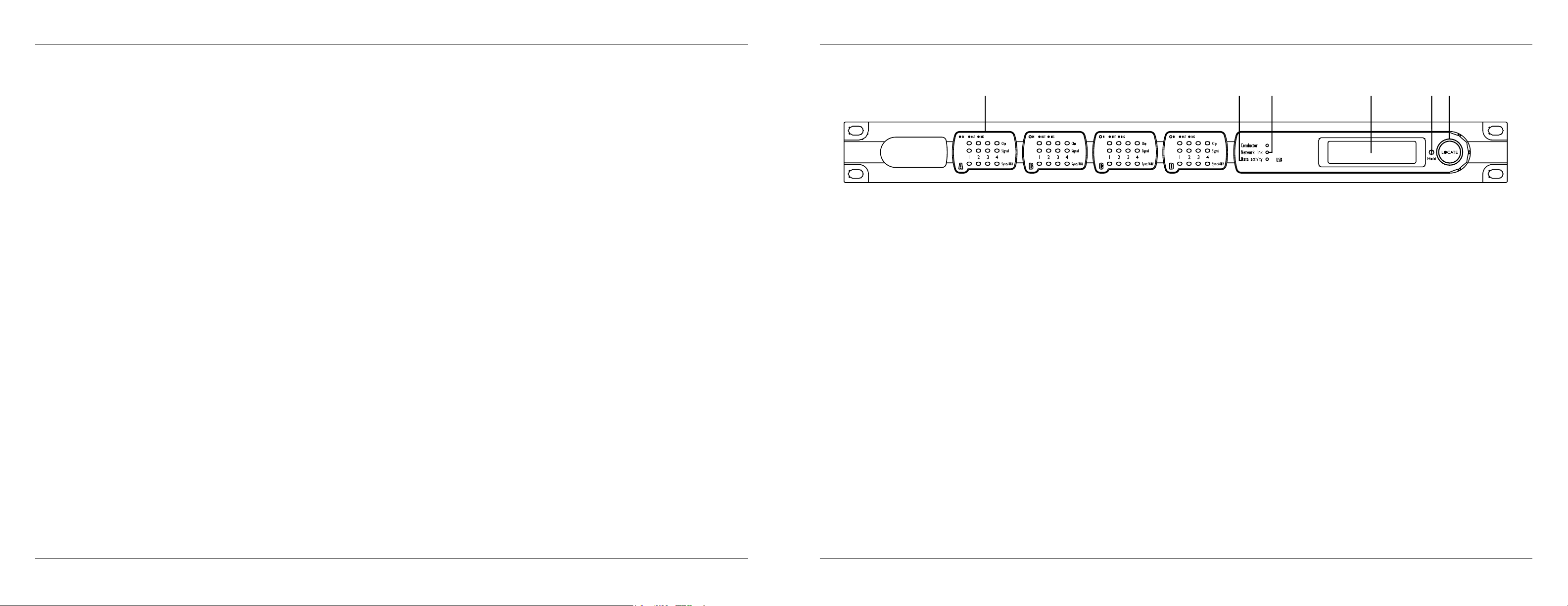
FRONT PANEL CONTROLS & INDICATORS
B C D E F G
B INPUT/OUTPUT CARD MONITORING: Each channel has three LED indicators showing:
CLIP – Indicates clipping in the analog domain for each channel of the fitted input or output
card. The LED will light at +18.5dB.
SIGNAL – The signal LED will light for each channel of a fitted input or output card when the
signal reaches or exceeds the signal threshold of – 20dB.
SYNC/48V – This feature is currently not supported by JBL Synthesis (lights to indicate that
+ 48V “phantom” power has been activated for the relevant channel of a fitted input card or
that Digital Sync is valid).
C DATA ACTIVITY: The data activity LED ashes when the SDEC is communicating with another
control device, either on the network or via the serial or control ports.
D NETWORK LINK: The network link LED indicates the presence of Ethernet cables. If no cables
are connected, the LED will be dark. The network link is used for conguring and calibrating the
Synthesis system when using the DACS calibration.
E INFORMATION DISPLAY: The information display indicates the name/ID and IP address of
the unit.
F HOLD: Press and hold this button to cycle the Information Display cycle the LCD through its
contrast range.
G LOCATE: Press this button to illuminate the Locate button on the rear panel.
3
-
2
-
-
-
Page 4

JBL SYNTHESIS SDEC-3500/SDEC-4500 JBL SYNTHESIS SDEC-3500/SDEC-4500Rear Panel Connections
Input/Output Assignments
REAR PANEL CONNECTIONS
H I J K L M N
BlueLink
H POWER CORD SOCKET: Connect the power cord here and then connect to to a mains
output with voltage from 85V to 270V, 50/60Hz.
I LOC ATE: Press this button to illuminate the Locate button on the front and identify the device
within the London Architect software.
J RS -232: This connection for external calibration and conguration unit is not active at this time.
K
ETHERNET: This is the main connection for the proprietary system control network, and for
third-party Ethernet control. The SDEC must be connected to an Ethernet hub during the
calibration process.
L
BLU-Link CONNECTORS:
products to enable BLU-Link to send and receive audio data. Please Note: When using the
SDEC-4500X or SDA Series amplifiers with BLU-Link you must connect the two units through
the BlueLink connection, using a
Cat. 5e patch cable.
M
CONTROL INPUTS
by using these control inputs. The SDEC-3500 does not need or use this connection.
N
INPUT/OUTPUT CARD POSITIONS
connections for the input/output card fitted in the four card slots in a JBL Synthesis SDEC
device. A green LED next to the slot assignment letter A, B, C or D indicates that an input
card is fitted and an amber LED when an output card is fitted. The analog connections are
balanced/unbalanced, on Phoenix/Combicon connectors. Depending on which model and
configuration you have purchased will determine which input/output card has been installed
at the factory. Please make certain that you have ordered the correct wiring kit for your
application and system configuration as designed and recommended by JBL Synthesis.
Connect these ports to other SDEC-4500P and SDEC-4500X
: The SDEC-4500P can be configured for full-range or bi-amp operation
: These connectors provide the balanced and unbalanced
INPUT/OUTPUT ASSIGNMENTS
SDEC-3500
The SDEC-3500 supports up to 7.1 input with up to 7.1 output. The input and output
assignments are described in the table below. You must make the correct connections from the
surround processor output to the amplifier input for the system to work correctly.
The correct Synthesis Interconnect kit includes all the necessary connections for using the SDEC
in the Synthesis system.
CONNECTION NOTES
• Please follow the Input/Output Assignments table for correct connections.
• You will need to use the Ethernet network port on the rear panel of the unit for the final
calibration process. You can connect the SDEC-3500 through any standard Ethernet hub.
SDEC-3500 INPUT/OUTPUT ASSIGNMENTS
Surround Processor to SDEC-3500 Inputs
Number Channel SDEC-3500
1 Left Front A1
2 Right Front A2
3 Center Front A3
4 Left Side A4
5 Right Side B1
6 Left Rear B2
7 Right Rear B3
8 Subwoofer B4
SDEC-3500 Outputs to Ampliers
Number Channel SDEC-3500
9 Left Front C1
10 Right Front C2
11 Center C3
12 Left Side C4
13 Right Side D1
14 Left Rear D2
15 Right Rear D3
16 Subwoofer D4
5
-
4
-
-
-
Page 5

JBL SYNTHESIS SDEC-3500/SDEC-4500 JBL SYNTHESIS SDEC-3500/SDEC-4500Input/Output Assignments
Input/Output Assignments
SDEC-4500
The SDEC-4500 is comprised of one SDEC-4500P plus either an SDEC-4500X or a combination
of SDA Series amplifiers with BLU-Link digital connection capability. The BLU-Link digital
connection carries all necessary signals on a single Cat.5e cable.
The correct Synthesis Interconnect kit includes all the necessary connections for using the SDEC
in the Synthesis system. Please contact JBL Synthesis Technical Support at 888-691-4171 (USA
only) for more information.
The SDEC-4500 is capable of processing up to 12 inputs and up to 22 outputs. Depending on
the type and number of outputs will determine which connections you should use to connect the
SDEC to the rest of your system.
CONNECTION NOTES
• The SDEC-4500 can process two outputs for the front left, center and right channels to
output to an amplier for a bi-amplied system. There are discrete outputs for a single
high-frequency horn speaker and low-frequency speakers. These outputs can only be used
with speakers designed to be used with an external crossover. Do not use the SDEC Digital
Equalizer for any speakers other than the recommended Synthesis speaker packages.
• There are three pairs of outputs for side speakers. If you are only using one pair of side
speakers, then you may leave the second or third pair of outputs with no connection. If you
are using a second or third pair of side speakers, then you should connect the pair closest
to the front speakers to Output 1, the pair in the middle of the room to Output 2, and the
pair closest to the rear speakers to Output 3. The third pair of outputs may be switched to
become the rear height pair when using the A.R.C.O.S. software.
• There are up to four subwoofer outputs. You should use them in pairs so that you either
have two or four.
• When SDA Series amplifiers are used in a system with a BLU-Link connection from the
SDP-4500P instead of the SDEC-4500X you must carefully follow the installation and
connection diagrams contained in the SDA Series amplifier’s Setup and Installation Manual.
SELECTING FULL-RANGE OR BI-AMPED CONFIGURATION
There are two ways to select between bi-amped or full-range LCR operation.
Please note: Only Method One can be done on the control ports (without a computer).
Method Two requires a computer running the appropriate configuration software.
Please contact JBL Synthesis Technical Support for more information.
METHOD ONE: WITHOUT A COMPUTER
Full Range: With the SDEC powered up and running, connect Control Input 1 to “C” (common)
on the back of the unit for full range. This is a temporary contact and should not be left in place.
Bi-Amped: With the SDEC powered up and running, connect Control Input 2 to “C” for biamped. This is a temporary connection and should not be left in place.
METHOD TWO: WITH A COMPUTER
While online and in Operate mode from within London Architect™ or when using the Java
remote, select the appropriate speaker configuration as your installation requires. The software
will automatically configure the outputs correctly.
SDEC-4500 WITH BI-AMPLIFIED FRONT SPEAKERS
This configuration requires the selection of bi-amplified operation, as noted on page 6.
Surround Processor to SDEC-4500P Inputs
Number Channel SDEC-4500P
1 Left Front A1
2 Right Front A2
3 Center Front A3
4 Left Side A4
5 Right Side B1
6 Left Rear B2
7 Right Rear B3
8 Subwoofer B4
9 Left Front Height C1
10 Right Front Height C2
11 Left Rear Height C3
12 Right Rear Height C4
SDEC-4500X Outputs to Ampliers
Number Channel SDEC-4500X
17 Left Front-Low A1
18 Left Front-Hi A2
19 Right Front-Low A3
20 Right Front-Hi A4
21 Center-Low B1
22 Center--Hi B2
23 Left Side 1 B3
24 Right Side 1 B4
25 Left Side 2 C1
26 Right Side 2 C2
27 Left Side 3 C3
28 Right Side 3 C4
29 Left Rear D1
30 Right Rear D2
31 Left FrontHeight D3
32 Right Front Height D4
SDEC-4500P Outputs to Ampliers
Number Channel SDEC-4500P
13 Subwoofer 1 D1
14 Subwoofer 2 D2
15 Subwoofer 3 D3
16 Subwoofer 4 D4
7
-
6
-
-
-
Page 6

JBL SYNTHESIS SDEC-3500/SDEC-4500 JBL SYNTHESIS SDEC-3500/SDEC-4500Input/Output Assignments
Specications
SDEC-4500 WITH FULL-RANGE FRONT SPEAKERS
This is the default configuration.
Surround Processor to SDEC-4500P Inputs
Number Channel SDEC-4500P
1 Left Front A1
2 Right Front A2
3 Center A3
4 Left Side A4
5 Right Side B1
6 Left Rear B2
7 Right Rear B3
8 Subwoofer B4
9 Left Front Height C1
10 Right Front Height C2
11 Left Rear Height C3
12 Right Rear Height C4
SDEC-4500P Outputs to Ampliers
Number Channel SDEC-4500P
13 Subwoofer 1 D1
14 Subwoofer 2 D2
15 Subwoofer 3 D3
16 Subwoofer 4 D4
SDEC-4500X Outputs to Ampliers
Number Channel SDEC-4500X
17 Left Front A1
18 (Not Used) A2
19 Right Front A3
20 (Not Used) A4
21 Center B1
22 (Not Used) B2
23 Left Side 1 B3
24 Right Side 1 B4
25 Left Side 2 C1
26 Right Side 2 C2
27 Left Side 3 C3
28 Right Side 3 C4
29 Left Rear D1
30 Right Rear D2
31 Left Front Height D3
32 Right Front Height D4
SPECIFICATIONS
INPUTS
ELECTRONICALLY BALANCED ON PHOENIX/COMBICON REMOVABLE SCREW
CONNECTORS
MIC/LINE INPUTS: NOMINAL GAIN 0DB, ELECTRONICALLY SWITCHABLE
UP TO +48DB, IN +6DB STEPS, INPUT IMPEDANCE
3.5K OHMS
MAXIMUM INPUT LEVEL: +20DBU WITH 0DB INPUT GAIN (+8DBU WITH 12DB
GAIN)
CMRR: >75DB AT 1KHZ
EQUIV. INPUT NOISE (EIN): <–128DBU TYPICAL WITH 150 OHMS SOURCE
SDEC-3500: 8 INPUTS
SDEC-4500P: 12 INPUTS
OUTPUTS:
ELECTRONICALLY BALANCED ON PHOENIX/COMBICON REMOVABLE SCREW
CONNECTORS
MAXIMUM OUTPUT LEVEL: +19DBU
FREQUENCY RESPONSE: 20HZ – 20KHZ (+0.5/–1DB)
THD: <0.01% (20HZ – 20KHZ, +10DBU OUTPUT)
DYNAMIC RANGE: 108DB TYPICAL (22HZ – 22KHZ UNWEIGHTED)
CROSSTALK: <–75DB
SDEC-3500: 8 OUTPUTS
SDEC-4500P: 4 OUTPUTS WITH EXPANSION TO 20 WITH
SDEC-4500X OR 22 WITH SDA AMPLIFIERS
SDEC-4500X: 16 OUTPUTS
CONTROL NETWORK
BLU-Link RJ45 CONNECTOR
MAXIMUM CABLE LENGTH: 100M/300 FT. BETWEEN DEVICE AND
ETHERNET SWITCH
ETHERNET: 2 X RJ45 CONNECTORS
MAXIMUM CABLE LENGTH: 100M/300 FT. BETWEEN DEVICE AND
ETHERNET SWITCH
PANEL LED INDICATORS: SIGNAL PRESENT (PER INPUT), CLIP (PER INPUT),
SYNC/48V (PER INPUT),
LCD, CONDUCTOR ACTIVE, NET LINK ACTIVE, DATA
ACTIVITY
MAINS VOLTAGE: 85 – 270V AC, 50/60HZ
POWER CONSUMPTION: <35VA
GENERAL:
DIMENSIONS (H X W X D): 1-3/4" X 19" X 9-1/4" (44MM X 483MM X 235MM)
WEIGHT: 6.5 LB (3KG)
9
-
8
-
-
-
Page 7

HARMAN International Industries, Incorporated
© 2015 HARMAN In ternati onal Ind ustrie s, Incor porate d. All rig hts reser ved.
JBL and, J BL Synth esis are r egister ed trade marks
of Harman International Industries, Incorporated.
This doc ument sho uld not be construed a a commi tment on the par t of HARMAN Internati onal Indu stries, Incorpo rated. All fe atures, specica tions and the appeara nce of the produ ct are subje ct to change without notice.
HARMA N International I ndustr ies, Inc orporated, assu mes no responsi bilit y for any er rors that m ay appea r in this do cument.
Part No. 5057658 Rev. A
Printed in USA
8500 Ba lboa Bou levard, N orthr idge, CA 91329 USA
 Loading...